SIMULATION PRACTICE = THEORY ELSEVIER Simulation Practice and Theorq 6 ( 19% 1 213 -25-l The use of physical knowledge to guide formula manipulation in system modelling Received I July 1996; revised I May 1997 Abstract Very often. systems consist of subsystems which may be independently described. Object oriented modelling languages, as Dymola and Omola. allow models to be structured in independent submodels as systems are structured in subsystems. However, it is not an easy task to derive a mathematical model, suitable for simulation environments, from such a representation. Algebraic problems arise when the modelling tool attempts to solve the computational causality assignment in the equations. This paper discusses the advantages 01‘ physical causality analysis in object oriented modelling. A neu representation, uhich adds a layer of physical knowledge, is proposed in order to analyze the physical behaviour of mod& described in a modular way. The physical interactions in the model are derived before computational causality assignment is undertaken. An automated procedure to find the adequate mathematical representation of coupling phenomena is developed by means of ;I symbolic formula manipulation kernel. The proposed methodology allows object oriented and modular modelling. preserving the xystem model structure analogy. The algorithms developed could be applied to support well established object oriented modelling languages as Dymola and Omola. 8 1998 Elsevier Science B.V. K~~~~~Iw~/~: Object-oriented modelling (OOM ): Physical and computational causalit!; Re-use of models I. Introduction Nowadays, there is an increasing industrial interest in the use of simulation techniques. However. there are many industrial branches for which these techniques are seldom used. The reason for this could be the fact that the development ot mathematical models for complex systems is difficult and time consuming. To extend * Corresponding author. E-mail: juanjoj~sunaut.uab.rs ‘E-mail: tniquelia‘sunaut.uab.es ‘E-mail: i_gnasiinsunaut.uab.es 0978-3869 ‘98 $19.00 C 1997 Elsevier Science B.V All rights rescl-ved. P/I so92x-4869( 97 )00024-4

Welcome message from author
This document is posted to help you gain knowledge. Please leave a comment to let me know what you think about it! Share it to your friends and learn new things together.
Transcript
SIMULATION PRACTICE = THEORY
ELSEVIER Simulation Practice and Theorq 6 ( 19% 1 213 -25-l
The use of physical knowledge to guide formula manipulation in system modelling
Received I July 1996; revised I May 1997
Abstract
Very often. systems consist of subsystems which may be independently described. Object oriented modelling languages, as Dymola and Omola. allow models to be structured in independent submodels as systems are structured in subsystems. However, it is not an easy task to derive a mathematical model, suitable for simulation environments, from such a representation. Algebraic problems arise when the modelling tool attempts to solve the computational causality assignment in the equations. This paper discusses the advantages 01‘ physical causality analysis in object oriented modelling. A neu representation, uhich adds a
layer of physical knowledge, is proposed in order to analyze the physical behaviour of mod& described in a modular way. The physical interactions in the model are derived before
computational causality assignment is undertaken. An automated procedure to find the adequate mathematical representation of coupling phenomena is developed by means of ;I
symbolic formula manipulation kernel. The proposed methodology allows object oriented and modular modelling. preserving the xystem model structure analogy. The algorithms developed could be applied to support well established object oriented modelling languages
as Dymola and Omola. 8 1998 Elsevier Science B.V.
K~~~~~Iw~/~: Object-oriented modelling (OOM ): Physical and computational causalit!; Re-use of models
I. Introduction
Nowadays, there is an increasing industrial interest in the use of simulation techniques. However. there are many industrial branches for which these techniques are seldom used. The reason for this could be the fact that the development ot mathematical models for complex systems is difficult and time consuming. To extend
* Corresponding author. E-mail: juanjoj~sunaut.uab.rs ‘E-mail: tniquelia‘sunaut.uab.es
‘E-mail: i_gnasiinsunaut.uab.es
0978-3869 ‘98 $19.00 C 1997 Elsevier Science B.V All rights rescl-ved.
P/I so92x-4869( 97 )00024-4
the use of simulation techniques, some environments have been provided with
software tools that simplify the modelling task.
Very often, systems consist of subsystems which may be independently described. It would be interesting if a model could be structured in independent submodels as
systems are structured in subsystems. To preserve this system-model analogy, new
data structures have been developed by several research groups to support models
of basic physical elements in such a way that they could be reused automatically.
Simulation environments have been endowed with tools that enable them to
encapsulate subsystem descriptions. The nzmc’ro facility is an attempt to give capabili-
ties of modular descriptions to CSSL simulation languages [2]. However, the re-use
of macros is not straightforward. Consider an electrical resistor (described by Ohm’s
law). The equation described in the macro should be li=ZR if the resistor were
placed with a current source or Z= VI’R if it were placed with a voltage source. This
kind of data structure leads to several models describing one physical system, which
break down the systemttmodel structure analogy.
Despite the fact that several modelling environments have provided very good
results for some application fields (Spice, M.M.S., . ..) most of them lead to hard
constraints when models are used to satisfy other modelling purposes not previously specified. Model re-usability requires an independent definition of the model and its
context. Hence, model description can not be procedural since causality is assumed.
Declarative models supporting general equalities are indispensable.
Based on the ideas of object oriented programming, which assure modular code
reusability, a new modelling methodology (object oriented modelling) has emerged
and is presenting very good results [8]. These modelling languages (such as Omola
[9] and Dymola [5]) allow models to be represented as modular structures in which the behaviour description is hidden to end users and the model description is context
independent.
Basically, object oriented models consist of an encapsulated behaviour description
and an interface to describe the interaction between the model and its environment.
This interface is defined in terms of terminals. A terminal specifies the shared
variables between the internal description and its environment, which will be used
to describe external model relationships (not system interaction) in a mathematical
way.
When terminal variables are couples of flow and effort variables, causality can be
derived by the well known Bondgraph sequential causality assignment procedure,
where subsystems are represented by objects describing energy storage, energy trans-
formation and energy dissipation (like vertices in bondgraphs) and physical intercon- nections are represented by terminals describing power flow (like bonds in
bondgraph).
However, in the authors’ opinion, terminals, as they are conceived, break down the system model structure analogy: a proper description of system interaction
cannot be determined easily by just analyzing the shared variables [4]. Furthermore, terminals themselves are not context independent. When systems interact through a
medium which flows between them, it can appear an interaction, derived from the
mass transport, that would require the use of complicated terminals. The dc\,elop-
ment of a model is conditioned by this fact [ 1 I]. On the other hand. terminals are conceived to facilitate the determination 01‘ the
overall model computational causality. However, two well-known problems somc- times appear when this model is generated: trl~qehic~ loops (system of simultaneous equations) and .str.uc.turn/l~* sir~,g~rhr- ~mc/~~/.r (high index problem) [ I].
The modelling methodology proposed tries to overcome some of these problems by incorporating extra modelling rules into the sequential causality assignment procedure of bondgraphs to deal with subsystem physical context. As a result. ;I functional model represented as a graph is generated automatically. The main
characteristic of this graph with respect to bondgraphs is that the vertices (nodes 01‘ the graph) always represent one single physical phenomenon, even Cohen it is a
coupling phenomenon associated to the interaction of se\,eral subsystems. In these situations. which often lead to algebraic problems. the behaviour represented in several interconnected submodels is automatically manipulated in order to find the mathematical description of the coupling phenomenon due to subsystems interaction. At present. the results are quite satisfactory and the algorithms developed could bc applied to state functional models as a suitable representation for using ~~11 estab- lished modelling tools. for instance. a bondgraph modelling environment or an
object oriented modelling language such as Dymola. Additionally. the proposed methodology allo~\~ object oriented and modular
modelling, preserving the system model structure analog) even in thelmod~nan~ical
systems where the physical interactions derived from mass transport often introduce modelling difficulties.
In this paper a modelling tool is proposed under the object-oriented paradigm that aLsoids some important constraints. Section 3 introduces the model representa-
tion and outlines the modelling tool developed to determine physical causalit!. In Section 3 a method for avoiding algebraic problems is described. Section 4 illustrates
the main ideas by nteans of an example.
2. Model representation
A model is an abstraction of the world, i.e. a representation of our knowledge
about the world. Modelling should be a matter of having the most convenient tools to specify models. Representations of systems as circuit diagrams or flo\vsheets are familiar to most engineers. Those representations preserve the topological structure of a system. Unfortunately, a model definition according to system topology, does not always preserve the computational structure suitable for simulation. In this section a new kind of model description is presented. The topological structure 01 the system is preserved and a suitable computational structure is derived.
It is feasible for an engineer to apply to physical principles in order to make an abstraction of the laws ruling the phenomena and the physical relationships present in a system. By analogy. it would be desirable that in a model all the phenomena
246 J. J. Rarnos et al. / Simhtion Practice mu Theory 6 ( 1998) 243-254
and the physical relationships could be derived by analyzing the topology of connec- tions between submodels.
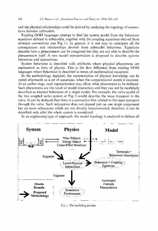
Existing OOM languages attempt to find the system model from the behaviour equations defined in submodels, together with the coupling equations derived from terminal connections (see Fig. 1). In general, it is not easy to anticipate all the
consequences and relationships derived from submodel behaviour. Equations describe how a phenomenon can be computed but they are not able to describe the phenomenon itself. A new model representation is proposed to describe systems behaviour and interactions.
System behaviour is described with attributes where physical phenomena are represented as laws of physics. This is the first difference from existing OOM languages where behaviour is described in terms of mathematical equations.
In the methodology depicted, the representation of physical knowledge can be stated afterwards as a set of equations, when the computational model is required. At an earlier stage, such representation may allow other phenomena to be deduced. Such phenomena are the result of model interaction and they can not be modularly described as internal behaviour of a single model. For example, the valve model of
the two coupled tanks system at Fig. 2 would describe the mass transport in the valve. It can be deduced that there is a convective flow related to the mass transport through the valve. Such interaction does not depend just on one single component but on more subsystems which are not directly interconnected, therefore, it can be described only after the whole system is considered.
In an engineering type of approach, the model topology is analyzed to deduce all
- Energy Balace + - Cause-Effect Relations
Terminals + Behaviour Description
Automated Formula
Manipulation
Fig. 1. The modelling process.
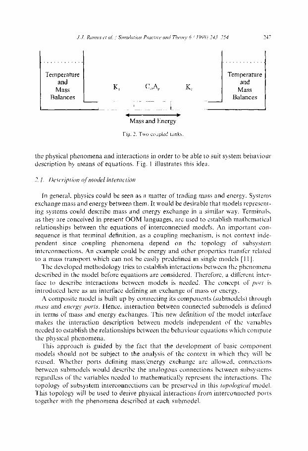
the physical phenomena and interactions in order to be able to suit system behaviour description by means of equations. Fig. 1 illustrates this idea.
2.1. Description of model interaction
In general, physics could be seen as a matter of trading mass and energy. Systems exchange mass and energy between them. It would be desirable that models represent- ing systems could describe mass and energy exchange in a similar way. Terminals. as they are conceived in present OOM languages, are used to establish mathematical relationships between the equations of interconnected models. An important con- sequence is that terminal definition, as a coupling mechanism, is not context inde- pendent since coupling phenomena depend on the topology of subsystem interconnections. An example could be energy and other properties transfer related to a mass transport which can not be easily predefined in single models [ 111.
The developed methodology tries to establish interactions between the phenomena described in the model before equations are considered. Therefore. a different inter-
face to describe interactions between models is needed. The concept of /XJV~ is introduced here as an interface defining an exchange of mass or energy.
A composite model is built up by connecting its components (submodels) through nr~tss and energy ports. Hence, interaction between connected submodels is defined in terms of mass and energy exchanges. This new definition of the model interface makes the interaction description between models independent of the variables needed to establish the relationships between the behaviour equations which compute the physical phenomena.
This approach is guided by the fact that the development of basic component models should not be subject to the analysis of the context in which they will be reused. Whether ports defining mass/energy exchange are allowed, connections
between submodels would describe the analogous connections between subsystems regardless of the variables needed to mathematically represent the interactions. The topology of subsystem interconnections can be preserved in this topologid model. This topology will be used to derive physical interactions from interconnected ports together with the phenomena described at each submodel.
2.2. Plzysicul cuusrrlity analysis
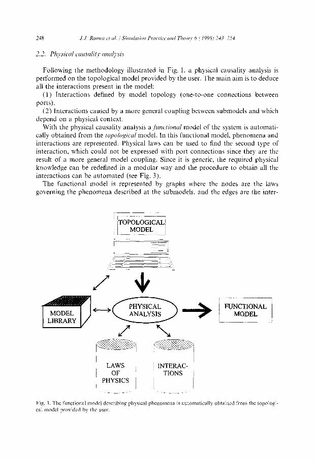
Following the methodology illustrated in Fig. 1, a physical causality analysis is
performed on the topological model provided by the user. The main aim is to deduce all the interactions present in the model:
( 1) Interactions defined by model topology (one-to-one connections between
ports). (2) Interactions caused by a more general coupling between submodels and which
depend on a physical context. With the physical causality analysis a jiinctiorzal model of the system is automati-
cally obtained from the topological model. In this functional model, phenomena and interactions are represented. Physical laws can be used to find the second type of interaction, which could not be expressed with port connections since they are the result of a more general model coupling. Since it is generic, the required physical knowledge can be redefined in a modular way and the procedure to obtain all the interactions can be automated (see Fig. 3).
The functional model is represented by graphs where the nodes are the laws governing the phenomena described at the submodels, and the edges are the inter-
Fig. 3. The functional model describing physical phenomena is automatically obtained from the topologi-
cal model provided by the user.
actions between those phenomena. Two kind of graphs representing the mass and energy paths between submodels are obtained. Therefore, a complete knowledge about all physical phenomena and interactions is achieved.
These information structures will allow a modular representation of the equations describing the behaviour and the interactions obtained from the topological model. Once this modular representation is established. currently available OOM languages.
such as Dymola or Omola. can be used to solve the computational causality assign- ment in order to simulate the overall system behaviour. This procedure \vill be illustrated in the example of Section 4.
3. The computational causality assignment problem
Achieving :I suitable computational model for a system is not mereI), a question of having a proper modular description of interaction between models. Algebraic problems, as systems of simultaneous equations or high index DAE’s, sometimes arise as a result of some topologies of submodel interconnections when deriving ;I
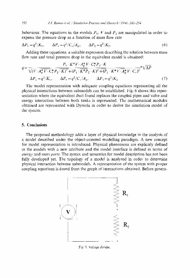
suitable model for simulation. The model for a voltage divider (see Fig. 5) is commonly used to illustrate the problem of systems of simultaneous equations [ I]. New modelling languages introduce different solutions in order to solve algebraic problems [6. lO,7]. The system of the example can be solved since it is linear but this is not always the case when nonlinear equations are involved.
The problem of computational causality assignment can be significantly simplified when physical laws are considered. In the voltage divider, for example, the current through two resistors in series is unique and the total voltage drop equals the sum
of the individual voltage drops. Applying these basic laws to the analysis of the circuit, it is found that the behaviour of both resistors is the same as the beha\,iout of one resistor where the resistance parameter is R, + R2. Ohm’s law for one resistor can be generalized to the case of several resistors in series. The problem of simulta- neous equations is avoided if an equivalent mode1 describing this generalized behavi- our is used instead of the two resistor models.
Whether a topology of mode1 connections leads to algebraic problems or not could be included in the physical analysis of the models. In the mode1 representation depicted, the laws ruling each submodel and the physical interactions between them are knoun. By tracing the mass and energy paths. it is possible to find situations in which interconnected submodels could lead to algebraic problems. An equivalent model to describe the resulting coupling phenomenon should be found in order to avoid the algebraic problem.
So as to preserve generality. it is necessary to find how an equivalent model interface and behaviour have to be derived without requiring specific algorithms for each particular case. It could be achieved by analyzing the physical phenomenon resulting of the coupled behaviour. The way in which interaction defines this coupling phenomenon could be viewed as a procedure to guide a formula manipulation kernel to handle the behaviour equations of each submodel.
For example, systems of simultaneous equations are found uhen resistive models
250 J. J. Rurrws et ~1. ! Simdution Practiw uml Theoq, 6 i 1998) 243-254
describing a causeoeffect relationship are connected in series. From the point of view of physical interaction with their environment, there is no difference between the coupled submodels and their counterparts. Hence, the interface of the equivalent
model can be defined as the interface of any submodel. Resistive elements are usually defined in terms of @iivt quantities (drops of voltages, pressures, temperatures, etc.) andfloir quantities (current, flow rate, heat, etc.) relationships. When resistive models are connected in series, the total effort is the sum of partial effort quantities and the flow quantity is the same at each submodel. This fact, gives the procedure to apply to submodels behaviour equations in order to find the equivalent coupled model behaviour.
This idea can be explained through the voltage divider circuit example. The behaviour of the resistors is described by Ohm’s law, mathematically expressed as
u1 =ifR,, u2 =ig R,. (1)
A symbolic formula manipulation kernel has been developed in Maple [3] to obtain the mathematical representation of the equivalent model behaviour. Equations at each submodel are analyzed to see how the cause-effect relationship is described. By automated formula manipulation, equalities in which the effort variables have been isolated, are obtained.
Since resistors are connected in series, the current is unique and the total voltage drop is the sum of partial voltage drops. This coupling phenomenon can be mathe-
matically expressed as
l&q =u, +u,, i,, =i, =i,. (2)
This fact gives the procedure to manipulate the mathematical description of the behaviour of the resistors. Hence, equalities in Eq. (1) can be added in order to obtain the mathematical relationship between the total effort and the flow quantities.
Such a relationship describes the coupled behaviour and can be used to define the equivalent model as
u eq =(R, +R2)*L,, u1 =R”i 1 eq, u,=R*i 2 eq’ (3)
Whether these equations are used in the mathematical representation of the system, the problem of simultaneous equations is avoided.
4. A modelling example
In order to model the system in Fig. 2, two classes of models predefined in a model library are used. The tank model class defines two phenomena: a muss balance
and a therm& balunce, as well as a muss port to specify the output point of mass (it is considered that the energy leaving or entering the tank is related to the mass transport).
Analogously, the duct model class defines a muss transport and the muss ports at both ends. The topological model of the two coupled tanks is defined by deriving
its components from the previous model classes and connecting them in the same
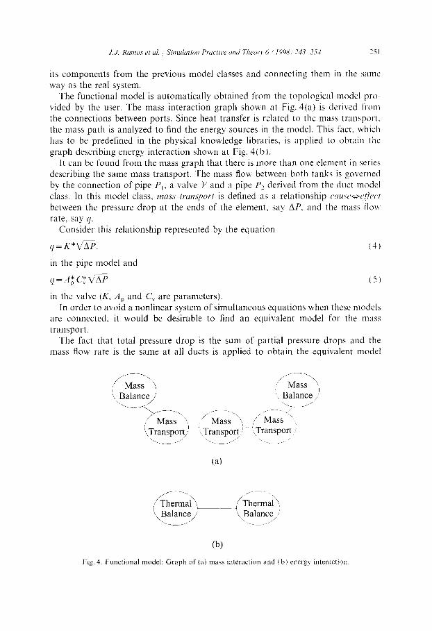
way as the real system. The functional model is automatically obtained from the topological model pro-
vided by the user. The mass interaction graph shown at Fig. 4(a) is deriv,ed from the connections between ports. Since heat transfer is related to the mass transport. the mass path is analyzed to find the energy sources in the model. This fact. which has to be predefined in the physical knowledge libraries, is applied to obtain the
graph describing energy interaction shown at Fig. 4(b). It can be found from the mass graph that there is more than one element in series
describing the same mass transport. The mass flow between both tanks is governed by the connection of pipe P,, a valve V and a pipe P2 derived from the duct model
class. In this model class, wms trmsport is defined as a relationship c~nu.rc~ocffi~~~t between the pressure drop at the ends of the element. say AP. and the mass tlo~ rate, say y.
Consider this relationship represented by the equation
4= K+G. (4)
in the pipe model and
q=A;Cy*V’rP (5)
in the valve (K, A, and C, are parameters). In order to avoid a nonlinear system of simultaneous equations when these models
are connected. it would be desirable to find an equivalent model for the mass transport.
The fact that total pressure drop is the sum of partial pressure drops and the mass flow rate is the same at all ducts is applied to obtain the equivalent model
,.__/ ‘. ___ , /I
(4
(b) Fig. 4. Functional model: Graph of (a) mars interaction and (b) energ) interaction
252 J. J. Rmnos et 01. / Sinadution Practice and Theory 6 (IV%?) 243-254
behaviour. The equations in the models P,, V and P, are manipulated in order to
express the pressure drop as a function of mass flow rate
AP, = q2/K,, AP, = q2/WA,, AP, = q2/K2. (6)
Adding these equations, a suitable expression describing the relation between mass flow rate and total pressure drop in the equivalent model is obtained:
P,.K*V.A;V.C,*P2.K
‘=~(V.A~*V.C~P~.K)~+(P~.K*P~.K)~+(P~.K*V.A~*V.C”)~ *$G
Ap, = q21K, > BP, =q’/C,JA,, AP, = q21K2 (7)
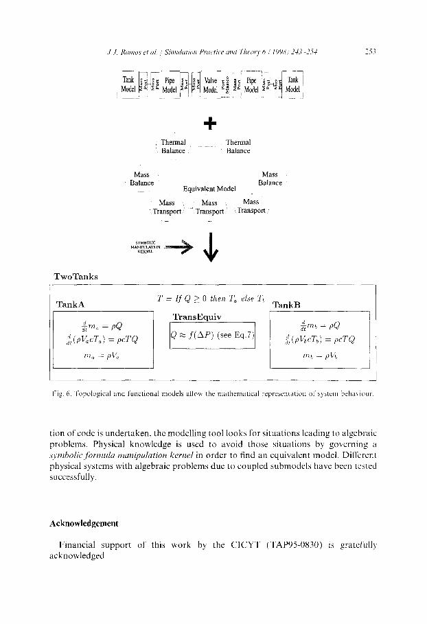
The model representation with adequate coupling equations representing all the physical interactions between submodels can be established. Fig. 6 shows this repre- sentation where the equivalent duct found replaces the coupled pipes and valve and energy interaction between both tanks is represented. The mathematical modules obtained are represented with Dymola in order to derive the simulation model of
the system.
5. Conclusions
The proposed methodology adds a layer of physical knowledge in the analysis of a model described under the object-oriented modelling paradigm. A new concept for model representation is introduced. Physical phenomena are explicitly defined in the models with a new attribute and the model interface is defined in terms of energy and muss ports. The syntax and semantics for model description has not been
fully developed yet. The topology of a model is analyzed in order to determine physical interaction between submodels. A representation of the system with proper
coupling equations is found from the graph of interactions obtained. Before genera-
Fig. 5. Voltage divider.
‘i7 -.
Thermal Thermal Balance Balance
Mass Balance
Equivalent Model
Mass Balance
; Mass ,, _ Mass Mass Transport Transport in Transport
TwoTanks
TankA T = If Q 2 0 then T, else Tb
TankB
Fis. 6. Topological and functional models allow the mathematical reprcscntation of system beha\ iout-
tion of code is undertaken, the modelling tool looks for situations leading to algebraic
problems. Physical knowledge is used to avoid those situations by governing a .s~tnholic,ji,rmukr manipulation kernel in order to find an equivalent model. Different physical systems with algebraic problems due to coupled submodels have been tested successfully.
Acknowledgement
Financial support of this work by the CICYT (TAP950830) is gratefully acknowledged
254 J. J. Rrrmos et ~1. / Simulation Pructice and Theory 6 (1998) 243-254
References
[l] F.E. Cellier, H. Elmqvist, Automated formula manipulation supports object-oriented continuous-
system modeling, IEEE Control Systems 13 (1993).
[2] F.E. Cellier, Continuous System Modeling. Springer-Verlag, New York, 1991.
[3] B.W. Char, K.O. Geddes, G.H. Gonnet, M.B. Monagan, SM. Watt, Maple Reference Manual,
Watcom, Waterloo, Canada, 1988.
[4] C. De Prada, M.A. Piera, A methodology to describe system interaction in an object oriented
modeling environment. in: Proceedings of the Conference on Modelling and Simulation. ESM 94.
Barcelona, Spain, 1994. pp. 314-318.
[5] H. Elmqvist, Object-oriented modeling and automatic formula manipulation in dymola, in: SIMS’IS,
Scandinavian Simulation Society, 1993.
[6] H. Elmqvist, M. Otter, Methods for tearing system of equations in object-oriented modeling. in:
ESM’94, Modelling and Simulation. 1994.
[7] S.L. Campbell, K.E. Brenan, L.R. Petzold. Numerical Solution of Initial-Value Problems in
Differential-Algebraic Equations, North-Holland, New York, 1989.
[S] SE. Mat&on, Towards a new standard for modelling and simulation tools. in: SIMS Simulation
Conference, Applied Simulation in Industry, 1993.
[9] S.E. Mattsson. M. Andersson, Omola: An object-oriented modeling language, in: M. Jamshidi,
C.J. Herget (Eds.), Recent Advances in Computer Aided Control Systems Engineering, Studies in
Automation and Control. vol. 9, Elsevier Science Publishers, 1993, pp. 291-310.
[IO] S.E. Mattsson, G. Soderlind, Index reduction in differential-algebraic equations using dummy deriva-
tives, SIAM J. Sci. Stat. Comput. 14 (1993) 6777692.
[ 1 l] J.J. Ramos, Object-oriented modelling of flows in process systems, Internal Report: TFRT-7521.
Department of Automatic Control, Lund Institute ad Technology. Sweden, June 1994.
Related Documents