High Dependability Computing Program Modeling Dependability The Unified Model of Dependability Victor Basili Paolo Donzelli Sima Asgari Computer Science Department University of Maryland College Park, Maryland 20742 Technical Report CS-TR-4601 - UMIACS-TR-2004-43 June 2004

Welcome message from author
This document is posted to help you gain knowledge. Please leave a comment to let me know what you think about it! Share it to your friends and learn new things together.
Transcript

High Dependability Computing Program Modeling Dependability
The Unified Model of Dependability
Victor Basili Paolo Donzelli Sima Asgari Computer Science Department University of Maryland College Park, Maryland 20742 Technical Report CS-TR-4601 - UMIACS-TR-2004-43 June 2004
Abstract Individuals and organizations increasingly use sophisticated software systems from which they demand great reliance. “Reliance” is contextually subjective and depends on the particular stakeholder’s needs; therefore, in different circumstances, the stakeholders will focus on different properties of such systems, e.g., continuity, availability, performance, real-time response, ability to avoid catastrophic failures, capability of resisting adverse conditions, and prevention of deliberate privacy intrusions. The concept of dependability enables these various concerns to be subsumed within a single conceptual framework.
Achieving dependability is a major challenge, which has spawned many efforts both at national and international levels. This work is part of the High Dependability Computing Program (HDCP), a five-year cooperative research agreement between NASA and various universities and research centers to increase NASA’s ability to engineer highly dependable software systems.
HDCP brings together, under the common goal of improving systems dependability, a large and heterogeneous group of actors, from industry and academia alike, with various perspectives, and different (sometimes even conflicting) needs. Thus, the polysemous nature of the concept of dependability, while unifying so many different efforts, brings also the risk of creating confusion, making the task of developing dependable systems even more difficult.
From this perspective, the Unified Model of Dependability (UMD) aims to establish a common language for discussing a variety of dependability attributes, and to make them measurable. To capture stakeholders’ dependability needs and perspectives, UMD takes into account different aspects of a dependability attribute, including the affected system functionalities, the acceptable manifestation of a specific failure (hazard) or class of failures (hazards), the external events (adverse conditions, attacks, etc.) that can create an unreliable system, and the expected system reaction to mitigate failures (hazards) impact over the stakeholders.
By providing a structured approach to eliciting and organizing both functional and non-functional dependability requirements, UMD helps the stakeholders to better express their needs, understand interactions among the dependability attributes, and set the corresponding values.
In order to illustrate the features and capabilities of UMD, an Air Traffic Control System is used as case study.

Table of Contents 1 Introduction........................................................................................................................... 4 2 The Unified Model of Dependability (UMD) .................................................................. 6
2.1 Identifying the building blocks of dependability .................................................... 6 2.2 “Robustness” of UMD.............................................................................................. 10 2.3 UMD to capture stakeholders dependability needs .............................................. 14 2.4 Measuring dependability .......................................................................................... 16 2.5 Enhancing UMD: capturing the “System Reaction” ............................................ 17 2.6 The UMD Tool .......................................................................................................... 19
3 Applying UMD to build a System Dependability Model ............................................. 19 3.1 The case study – TSAFE .......................................................................................... 19 3.2 Data Gathering........................................................................................................... 21 3.3 Data Analysis ............................................................................................................. 24
4 Formalizing the UMD application process..................................................................... 28 4.1 The single-stakeholder scenario .............................................................................. 28 4.2 The multiple-stakeholder scenario .......................................................................... 29
5 Conclusions and future work............................................................................................ 30 6 References........................................................................................................................... 31 Appendix A – Description of the UMD Tool ......................................................................... 33
3

1 Introduction
Individuals and organizations increasingly use sophisticated software systems from which they demand great reliance. “Reliance” is contextually subjective and depends on the particular users’ needs, therefore, in different circumstances, stakeholders will focus on different properties of such systems, e.g., availability, performance, real-time response, ability to avoid catastrophic failures, capability of resisting adverse conditions, and prevention of deliberate intrusions, as well as different levels of adherence to such properties. The concept of dependability enables these various concerns to be subsumed within a single conceptual framework. The International Federation for Information Processing (IFIP) WG-10.4 [7] defines dependability as the trustworthiness of a computing system that allows reliance to be justifiably placed on the services it delivers.
Achieving systems dependability is a major challenge, and it has spawned many efforts at the national and international level, such as the European Dependability Initiative [14], the US Government strategy “Trust in cyberspace” [15], or the Critical Infrastructures improvement and protection initiatives adopted by various countries [10,16]. This work is part of the High Dependability Computing Program (HDCP), a five-year cooperative research agreement between NASA and various universities and research centers1, to increase NASA’s ability to engineer highly dependable software systems. The Program involves: a) understanding NASA’s dependability problems; b) developing new engineering practices and technologies to address such problems; c) empirically assessing (and iteratively improving) the capabilities of new practices and technologies, using realistic testbeds; d) transferring technologies to technology users with clear indications about their effectiveness under varying conditions.
HDCP brings together, under the common goal of improving systems dependability, a large and heterogeneous group of actors, from government and academia alike, with various perspectives, and different (sometimes even conflicting) needs. First, there are the actors directly involved in using, building, and developing systems or technologies:
• The system users, who are concerned mainly about the final system’s behavior, and who need to understand whether or not, and to what extent, they can depend upon a system to achieve their goals.
• The system developers (or technology users), who need to know which processes and or technologies should be selected to meet the system users’ needs in the most efficient and effective way.
• The technology researchers/developers, who focus on specific means to develop dependable systems [1].
• The empiricists, whose role is to help the users define dependability needs, support the developers in selecting the right approaches, and provide empirical evidence of the technology’s ability to meet those needs. The empirical researchers act as “observers” to support the transfer of knowledge (needs, opportunities, technologies’ capabilities and limits) among the other actors.
1 The universities and research centers involved in HDCP are: Carnegie Mellon, University of Maryland, Fraunhofer Center Maryland, University of Southern California, Massachusetts Institute of Technology, University of Washington, University of Wisconsin, and many others
4
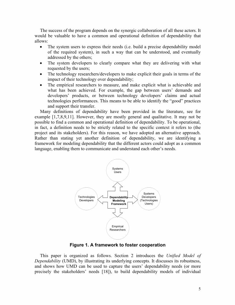
The success of the program depends on the synergic collaboration of all these actors. It would be valuable to have a common and operational definition of dependability that allows:
• The system users to express their needs (i.e. build a precise dependability model of the required system), in such a way that can be understood, and eventually addressed by the others;
• The system developers to clearly compare what they are delivering with what requested by the users;
• The technology researchers/developers to make explicit their goals in terms of the impact of their technology over dependability;
• The empirical researchers to measure, and make explicit what is achievable and what has been achieved. For example, the gap between users’ demands and developers’ products, or between technology developers’ claims and actual technologies performances. This means to be able to identify the “good” practices and support their transfer.
Many definitions of dependability have been provided in the literature, see for example [1,7,8,9,11]. However, they are mostly general and qualitative. It may not be possible to find a common and operational definition of dependability. To be operational, in fact, a definition needs to be strictly related to the specific context it refers to (the project and its stakeholders). For this reason, we have adopted an alternative approach. Rather than stating yet another definition of dependability, we are identifying a framework for modeling dependability that the different actors could adopt as a common language, enabling them to communicate and understand each other’s needs.
EmpiricalResearchers
SystemsUsers
SystemsDevelopers
(TechnologiesUsers)
TechnologiesDevelopers
DependabilityModeling
Framework
Figure 1. A framework to foster cooperation
This paper is organized as follows. Section 2 introduces the Unified Model of
Dependability (UMD), by illustrating its underlying concepts. It discusses its robustness, and shows how UMD can be used to capture the users’ dependability needs (or more precisely the stakeholders’ needs [18]), to build dependability models of individual
5
systems. A comparison with related work is also provided. Section 3 shows how the UMD can be customized to a specific context/project to obtain a system dependability model that can be used as operational dependability definition. A case study is used for illustration. Section 4 formalizes the process for applying UMD in both a single and a multi-stakeholder scenario. Finally, Section 4 provides an outline of the future work.
2 The Unified Model of Dependability (UMD)
This Section introduces UMD, by illustrating the underlying theory, and discusses its robustness. It also provides a comparison with related works.
2.1 Identifying the building blocks of dependability Dependability involves many different attributes, and each attribute can be defined in
a variety of ways. In order to begin our analysis for identifying the building blocks of dependability, around which we build UMD, let us consider a standard sub-set of such attributes: reliability, accuracy, performance, availability, survivability, security, maintainability, and safety. It is important to note that this choice is purely arbitrary, and any other set could have been adopted, as in the following we will show that our results are independent from the selected set. For each of these attributes different definitions are available in literature. In the following we have randomly chosen some of them from [1,4,9,13]: o Reliability is an index of how often the system or part of it fails. o Accuracy is the ability of the system to provide data within the desired range and with
the required precision. o Performance is a static or dynamic system’s capability (response time, throughput)
defined in terms of an acceptable range. o Availability is the degree to which a system or component is operational and
accessible when required for use. o Survivability is the ability of a system to provide essential services in the presence of
adverse conditions that can occasionally happen within its operational environment (e.g., exceptional weather conditions, un-natural load peaks, etc.).
o Security is the system’s capability to resist attacks intentionally carried on against the system (e.g., logical breaches, data accesses, denial of service attacks, etc.).
o Maintainability is the ability of the system to undergo repairs and modifications. o Safety is the absence of catastrophic consequences on the user(s) and the
environment. Based on the above definitions, we observe that dependability can be viewed as an
index of the issues that the system can cause to the users. In other terms, given two similar systems, the one that causes fewer, and less severe issues is the one that is more dependable for the users. By carefully reading the above definitions, we can also recognize that an issue may derive from the misbehavior of the system (e.g., the system fails, or is not available at a given time, or is not able to survive external adverse conditions), or because the system creates a situation that could lead to catastrophic consequences for the users or the environment (see definition of safety). For this reasons, we distinguish between two kinds of issues:
6

• Failure: any departure of the system behavior from the user’s expectations. • Hazard: a state of the system that can lead to catastrophic consequences for the
user(s) and the environment. Note that the concepts of hazard and failure are not exclusive, but overlap: a failure
may be also a hazard (i.e. a failure can lead to an accident), whereas a hazard can occur without a failure occurring. Given the chosen set of dependability attributes, then, we can further distinguish failures into different failure types:
• Accuracy failure: the departure of the system behavior from providing data within the desired range and with the required precision;
• Performance failure: the departure of the system behavior from providing the desired static or dynamic capability (response time, throughput);
• Other failure: any failure that cannot be classified as accuracy or performance failure.
In addition, having availability among the chosen dependability attributes, we can also distinguish failures according to their impact upon availability. For example, we can distinguish between:
• Stopping failure is any failure that makes the system unavailable. • Non-Stopping failure is any failure that does not make the system unavailable. It is worth noting that the above classifications in terms of Failures Types (accuracy,
performance, other) and Failure impact over availability (stopping, non-stopping) are orthogonal.
The same observations can be repeated for the hazards. Based on the above definition of safety, in fact, we can distinguish different hazards types:
• User(s) Hazard: a state of the system that can lead to catastrophic consequences for the user(s);
• Environment Hazard: a state of the system that can lead to catastrophic consequences for the environment.
Finally, from the above definitions (see for example reliability), we can also observe that the issues caused to the users by a system could result from the misbehavior of the whole system or of part of it, for example, a service or component. Thus, we can characterize an issue in terms of the part of the system that it affects. We distinguish the scope:
• The system, i.e., the whole system; • A service, i.e., a functionality delivered by the system, as perceived by the users (a
human or another interacting system). From this initial analysis, thus, it results that some concepts are common across the
different definitions, however, with different degrees of commonality and independence from the chosen set of attributes. The concept of issue (with the more elementary ones of failure and hazard) and the concept of scope are common across all the attributes and independent from the initial set. Each dependability attribute can in fact be defined in terms of some kind of issues affecting the whole system or part of it. The characterizations of failure, hazard and scope, instead, depend on the set of dependability attributes taken into account. For example, the distinction of failures into accuracy, performance and other failures is the result of the chosen sub-set of dependability attributes. Similarly, the idea of classifying failures according to their impact on availability results from having availability among the considered attributes. In this case,
7

in particular, the choice of distinguishing only between stopping and non-stopping failures is purely arbitrary. A finer distinction (e.g., stopping, partly stopping, and non-stopping) could be adopted in order to be able to model gradual services degradations.
The emerging concepts and their relationships are pictured in Figure 2. This structure represents the common backbone of the different dependability attributes definitions taken into account, and thus, it provides an initial structure for our framework. In Figure 2, to distinguish the UMD concepts with higher commonality and independence (i.e. issue, failure, hazard and scope) from the ones with lower commonality and independence (i.e., the characterizations), the latter are shown on a darker background. In the following, we refer to them as UMD Hardware component; and as UMD Software component, respectively.
scopeissue
characterization:- Type - Whole System - Service
characterization:- Type - User(s) hazard - Environment hazard
characterization:- Type - Accuracy failure - Performance failure - Other failure- Availability impact - Stopping - Non-Stopping
FAILURE
HAZARD
concern
Figure 2. The “emerging” UMD
By using the concepts of UMD, all the dependability attributes definitions taken into account can be reformulated. For example, we can define availability as the index of all the stopping failures, of any type (accuracy, performance, or others) (ISSUE) affecting the system or a service (SCOPE), where the definitions of stopping failures, and of accuracy, performance and other failures are the ones given above. Similarly, the definitions of the others dependability attributes introduced above become:
o Reliability: index of all the failures (ISSUE) affecting the system or a service
(SCOPE). o Accuracy: index of the accuracy failures (ISSUE) affecting the system or a service
(SCOPE). o Performance: index of the performance failures (ISSUE) affecting the system or a
service (SCOPE). o Availability: index of the stopping failures (ISSUE) affecting the system or a service
(SCOPE). o Survivability: index of all the failures (ISSUE) affecting the system or a service
(SCOPE), due to adverse conditions that can occasionally happen within its operational environment (e.g., exceptional weather conditions, un-natural load peaks, etc.).
8
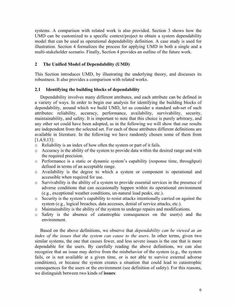
o Security: index of all the failures (ISSUE) affecting the system or a service (SCOPE), due to attacks intentionally carried on against the system (e.g., logical breaches, data accesses, denial of service attacks, etc.).
o Maintainability2: index of all the failures (ISSUE) affecting the system or a service (SCOPE), due to actions intentionally carried on to improve the system (e.g., repairs, upgrades).
o Safety: index of the hazards (ISSUE) created by the system or a service (SCOPE). At this point, we can start from these new definitions for refining our analysis. We
recognize that some failures (see the definitions of survivability, security, and maintainability) are the results of some external events. Due to our choice of the initial set of dependability attributes, we can distinguish three main external events types:
• Adverse condition: any external event that may have an actual or potential harmful effect on the system or a service (e.g., extreme weather conditions, un-natural load peaks, etc.);
• Attack: any intentional action carried on against the system or a service (e.g., logical breaches, data accesses, denial of service attacks, etc.);
• Update: any action intentionally carried on to change the system or a service (e.g., repairs, upgrades.).
event scopeissue
characterization:- Type - Whole System - Service
characterization:- Type - Adverse Condition - Attack - Upgrades
cause
characterization:- Type - User(s) hazard - Environment hazard
characterization:- Type - Accuracy failure - Performance failure - Other failure- Availability impact - Stopping - Non-Stopping
FAILURE
HAZARD
concern
Figure 3: The “evolving” UMD Thus, the concept of external event emerges as another common item across the
different definitions. Each dependability attribute can in fact be defined in terms of some kind of issues affecting the whole system or part of it (the scope), due or not due to some external events. Figure 3 extends the framework introduced in Figure 2, by encompassing the new concept of event
By using the new framework, the definitions of the dependability attributes become:
2 Note that with this new definition of maintainability we cover only partially the initial one. While the original definition encompasses, for example, the capability of the system of being repaired and/or upgraded within the expected budget and time, the new definition focuses only upon the easiness of the maintenance process, taking into account the possible issues caused by repairs and upgrades. UMD, however, also allows for the expression of the desired system behavior during maintenance, as will be illustrated in the Section “Capturing System reaction”.
9
o Reliability: index of all the failures (ISSUE) affecting the system or a service (SCOPE), which are due or not due to external events (EVENT).
o Accuracy: index of the accuracy failures (ISSUE) affecting the system or a service (SCOPE), which are due or not due to external events (EVENT).
o Performance: index of the performance failures (ISSUE) affecting the system or a service (SCOPE), which are due or not due to external events (EVENT).
o Availability: index of the stopping failures (ISSUE) affecting the system or a service (SCOPE), which are due or not due to external events (EVENT).
o Survivability: index of all the failures (ISSUE) affecting the system or a service (SCOPE), due to adverse conditions (EVENT).
o Security: index of all the failures (ISSUE) affecting the system or a service (SCOPE), due to attacks (EVENT).
o Maintainability: index of all the failures (ISSUE) affecting the system or a service (SCOPE), due to upgrades (EVENT).
o Safety: index of the hazards (ISSUE) created by the system or a service (SCOPE), which are due or not due to external events (EVENT).
It is important to note that these definitions reflect only some of the possibilities. In
fact, while we have defined accuracy as “an index of the accuracy failures, affecting the system or a service, which are due or not due to external events”, it would have been also possible to define it as “an index of the accuracy failures, affecting the system or a service, which are not due to external events”, clearly stating that accuracy failures due to external events are not to be considered as part of the accuracy of the system. This is also true for the other definitions. Thus, by reformulating the definitions around the identified framework, we have obtained definitions more precise than the original ones (where some aspects were left implicit). Put another way, the framework not only provides a guide to define the different attributes, but also helps to make explicit options that could have been neglected otherwise.
2.2 “Robustness” of UMD In order to see if UMD can really be adopted on a larger scale, that is, determine
whether it can encompass the many available definitions of dependability and its attributes, we will verify the capability of the framework to accommodate: a) different definitions of the dependability attributes already taken into account; b) other dependability attributes not included into the initial set.
Let us start by considering different possible definitions for the same dependability attributes. In the following, for each definition found in literature (Literature Definition – LD), we will provide corresponding definition expressed by using the framework (Framework Definition – FD), together with the necessary framework adjustments and extensions (FA).
o LD: Reliability is the continuity of correct service (a service is correct when implements the system function) [Laprie01].
FD: Reliability is index of all the failures (ISSUE) affecting the system or a service (SCOPE), which are due or not due to external events (EVENT). FA: none
10

o LD: Availability is the capability to maximize the function of time that the system will provide stakeholder-desired levels of service with respect to a system’s operational profile (probability distribution of transaction frequencies, task complexities, workload volumes, others) [Boehm03].
FD: Availability: index of the stopping failures (ISSUE) affecting the system or a service (SCOPE), with respect to a system’s operational profile, which are due or not due to external events (EVENT). FA: The adjustments concern the Software component of the Framework:
Stopping failures are defined as failures preventing the system from providing the stakeholder-desired levels of service. The system’s operational profile (probability distribution of transaction
frequencies, task complexities, workload volumes, others) is added as further Scope characterization.
o LD: Availability is the ability of the system to provide service at any given time. It is the probability of being operational, under given use condition, at a given instant in time [Melhart00].
FD: Availability: index of the stopping failures (ISSUE) affecting the system or a service (SCOPE), under given use condition, which are due or not due to external events (EVENT). FA: The adjustments and extensions concern the Software component of the Framework:
Use condition is added as further Scope characterization.
o LD: Accuracy is the capability to minimize the difference between delivered computational results and the real world quantities that they represent [Boehm03].
FD: Accuracy is an index of the accuracy failures (ISSUE) affecting the system or a service (SCOPE), which are due or not due to external events (EVENT) FA: The adjustments and extensions concern the Software component of the Framework:
Accuracy failures are defined as differences between delivered computational results and the real world quantities that they represent.
o LD: Survivability is the capability of the system to minimize the expected value of the information, property, human life and health losses due to natural causes [Boehm03].
FD: Survivability: index of all hazards (ISSUE) resulting from the system or a service (SCOPE), due to adverse conditions (EVENT). FA: The adjustments and extensions concern the Software component of the Framework:
Hazards are defined as system states that can lead to information, property, human life and health losses. Adverse conditions are defined as all natural causes.
11
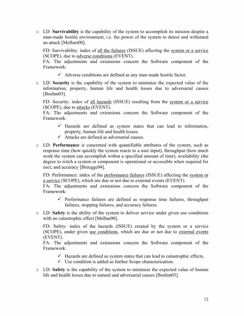
o LD: Survivability is the capability of the system to accomplish its mission despite a man-made hostile environment, i.e. the power of the system to detect and withstand an attack [Melhart00].
FD: Survivability: index of all the failures (ISSUE) affecting the system or a service (SCOPE), due to adverse conditions (EVENT). FA: The adjustments and extensions concern the Software component of the Framework:
Adverse conditions are defined as any man-made hostile factor.
o LD: Security is the capability of the system to minimize the expected value of the information, property, human life and health losses due to adversarial causes [Boehm03].
FD: Security: index of all hazards (ISSUE) resulting from the system or a service (SCOPE), due to attacks (EVENT). FA: The adjustments and extensions concern the Software component of the Framework:
Hazards are defined as system states that can lead to information, property, human life and health losses. Attacks are defined as adversarial causes.
o LD: Performance is concerned with quantifiable attributes of the system, such as response time (how quickly the system reacts to a user input), throughput (how much work the system can accomplish within a specified amount of time), availability (the degree to witch a system or component is operational or accessible when required for use), and accuracy [Bruegge04].
FD: Performance: index of the performance failures (ISSUE) affecting the system or a service (SCOPE), which are due or not due to external events (EVENT). FA: The adjustments and extensions concern the Software component of the Framework:
Performance failures are defined as response time failures, throughput failures, stopping failures, and accuracy failures.
o LD: Safety is the ability of the system to deliver service under given use conditions with no catastrophic effect [Melhar00].
FD: Safety: index of the hazards (ISSUE) created by the system or a service (SCOPE), under given use conditions, which are due or not due to external events (EVENT). FA: The adjustments and extensions concern the Software component of the Framework:
Hazards are defined as system states that can lead to catastrophic effects. Use condition is added as further Scope characterization.
o LD: Safety is the capability of the system to minimize the expected value of human life and health losses due to natural and adversarial causes [Boehm03].
12
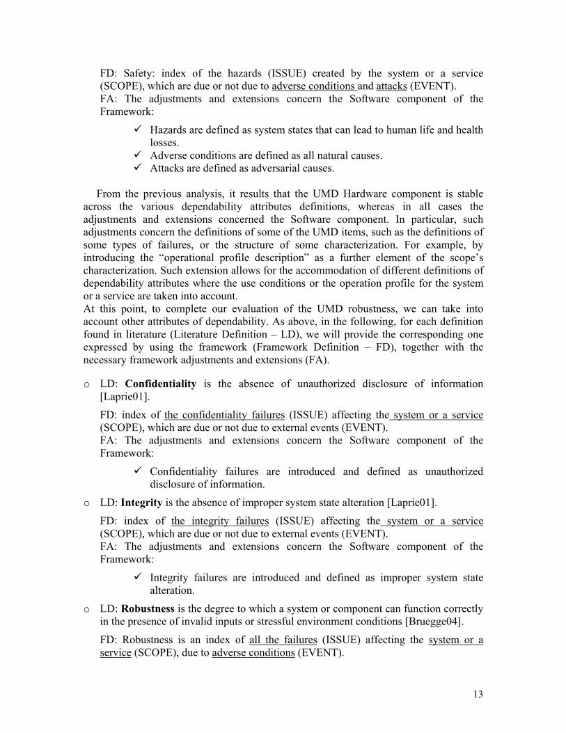
FD: Safety: index of the hazards (ISSUE) created by the system or a service (SCOPE), which are due or not due to adverse conditions and attacks (EVENT). FA: The adjustments and extensions concern the Software component of the Framework:
Hazards are defined as system states that can lead to human life and health losses. Adverse conditions are defined as all natural causes. Attacks are defined as adversarial causes.
From the previous analysis, it results that the UMD Hardware component is stable
across the various dependability attributes definitions, whereas in all cases the adjustments and extensions concerned the Software component. In particular, such adjustments concern the definitions of some of the UMD items, such as the definitions of some types of failures, or the structure of some characterization. For example, by introducing the “operational profile description” as a further element of the scope’s characterization. Such extension allows for the accommodation of different definitions of dependability attributes where the use conditions or the operation profile for the system or a service are taken into account. At this point, to complete our evaluation of the UMD robustness, we can take into account other attributes of dependability. As above, in the following, for each definition found in literature (Literature Definition – LD), we will provide the corresponding one expressed by using the framework (Framework Definition – FD), together with the necessary framework adjustments and extensions (FA).
o LD: Confidentiality is the absence of unauthorized disclosure of information [Laprie01].
FD: index of the confidentiality failures (ISSUE) affecting the system or a service (SCOPE), which are due or not due to external events (EVENT). FA: The adjustments and extensions concern the Software component of the Framework:
Confidentiality failures are introduced and defined as unauthorized disclosure of information.
o LD: Integrity is the absence of improper system state alteration [Laprie01].
FD: index of the integrity failures (ISSUE) affecting the system or a service (SCOPE), which are due or not due to external events (EVENT). FA: The adjustments and extensions concern the Software component of the Framework:
Integrity failures are introduced and defined as improper system state alteration.
o LD: Robustness is the degree to which a system or component can function correctly in the presence of invalid inputs or stressful environment conditions [Bruegge04].
FD: Robustness is an index of all the failures (ISSUE) affecting the system or a service (SCOPE), due to adverse conditions (EVENT).
13
FA: The adjustments and extensions concern the Software component of the Framework:
Adverse conditions are defined as invalid inputs or stressful environment conditions.
o LD: Correctness system implementation precisely satisfies its requirements and/or design specifications [Boehm03].
FD: Correctness is an index of the correctness failures (ISSUE) affecting the system or a service (SCOPE), which are due or not due to external events (EVENT). FA: The adjustments and extensions concern the Software component of the Framework:
Correctness failures are introduced and defined as improper system state alterations.
Again, the previous analysis reveals, that the Hardware component of the framework is stable across the various definitions of the various dependability attributes, whereas the Software component of the framework is flexible enough to accommodate the necessary adjustments and extensions.
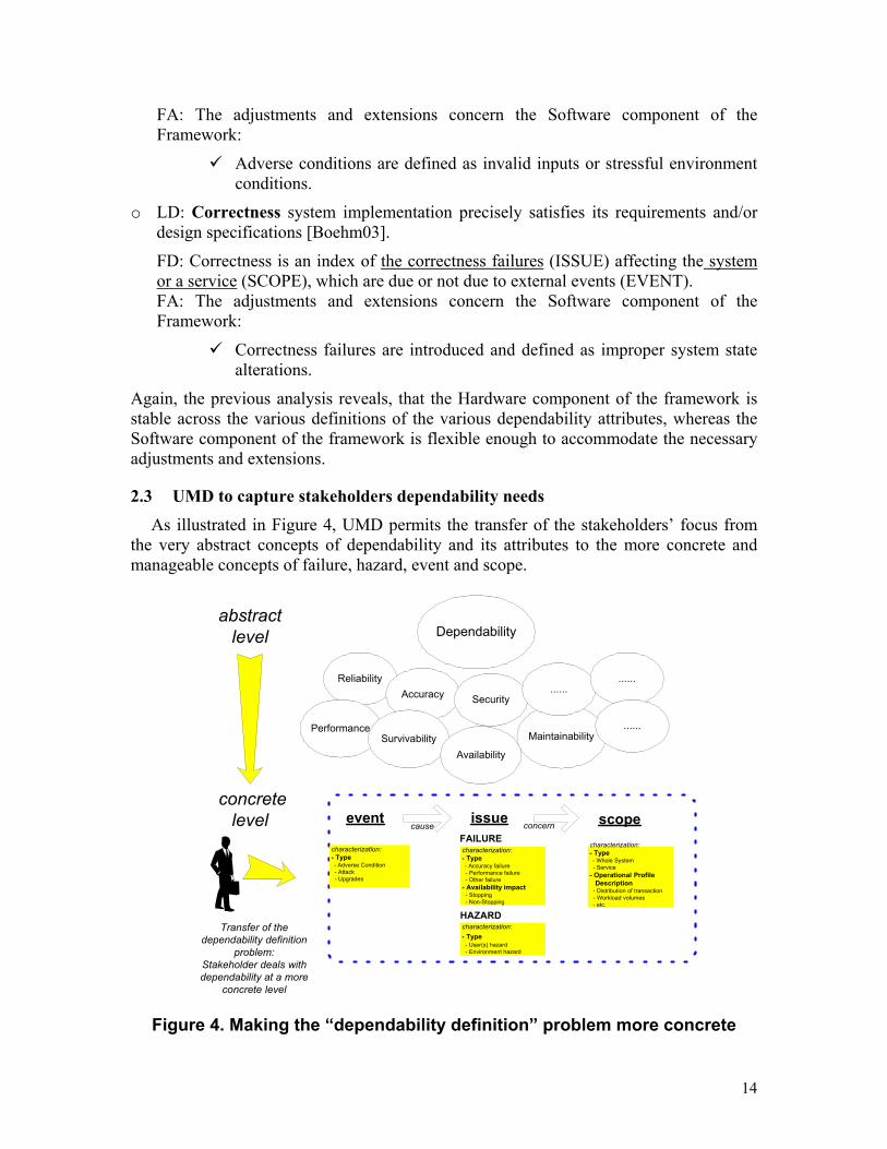
2.3 UMD to capture stakeholders dependability needs As illustrated in Figure 4, UMD permits the transfer of the stakeholders’ focus from
the very abstract concepts of dependability and its attributes to the more concrete and manageable concepts of failure, hazard, event and scope.
Dependabilityabstract
level
ReliabilityAccuracy
PerformanceSurvivability
Security
Maintainability
Availability
............
......
concretelevel
Transfer of thedependability definition
problem:Stakeholder deals withdependability at a more
concrete level
event scopeissuecharacterization:- Type - Whole System - Service- Operational Profile Description - Distribution of transaction - Workload volumes - etc.
characterization:- Type - Adverse Condition - Attack - Upgrades
cause
characterization:- Type - User(s) hazard - Environment hazard
characterization:- Type - Accuracy failure - Performance failure - Other failure- Availability impact - Stopping - Non-Stopping
FAILURE
HAZARD
concern
Figure 4. Making the “dependability definition” problem more concrete
14
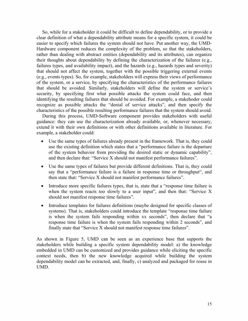
So, while for a stakeholder it could be difficult to define dependability, or to provide a clear definition of what a dependability attribute means for a specific system, it could be easier to specify which failures the system should not have. Put another way, the UMD-Hardware component reduces the complexity of the problem, so that the stakeholders, rather than dealing with abstract entities (dependability and its attributes), can organize their thoughts about dependability by defining the characterization of the failures (e.g., failures types, and availability impact), and the hazards (e.g., hazards types and severity) that should not affect the system, together with the possible triggering external events (e.g., events types). So, for example, stakeholders will express their views of performance of the system, or a service, by specifying the characteristics of the performance failures that should be avoided. Similarly, stakeholders will define the system or service’s security, by specifying first what possible attacks the system could face, and then identifying the resulting failures that should be avoided. For example, a stakehoder could recognize as possible attacks the “denial of service attacks”, and then specify the characteristics of the possible resulting performance failures that the system should avoid.
During this process, UMD-Software component provides stakeholders with useful guidance: they can use the characterization already available, or, whenever necessary, extend it with their own definitions or with other definitions available in literature. For example, a stakeholder could:
• Use the same types of failures already present in the framework. That is, they could use the existing definition which states that a “performance failure is the departure of the system behavior from providing the desired static or dynamic capability”, and then declare that: “Service X should not manifest performance failures”.
• Use the same types of failures but provide different definitions. That is, they could say that a “performance failure is a failure in response time or throughput“, and then state that: “Service X should not manifest performance failures”.
• Introduce more specific failures types, that is, state that a “response time failure is when the system reacts too slowly to a user input”, and then that: “Service X should not manifest response time failures”.
• Introduce templates for failures definitions (maybe designed for specific classes of systems). That is, stakeholders could introduce the template “response time failure is when the system fails responding within xx seconds”, then declare that “a response time failure is when the system fails responding within 2 seconds”, and finally state that “Service X should not manifest response time failures”.
As shown in Figure 5, UMD can be seen as an experience base that supports the stakeholders while building a specific system dependability model: a) the knowledge embedded in UMD can be customized and provides guidance while eliciting the specific context needs, then b) the new knowledge acquired while building the system dependability model can be extracted, and, finally, c) analyzed and packaged for reuse in UMD.
15

SystemContext
Framework customizationto the specific context
Extraction of the new knowledge to enrich UMD
Specific SystemDependability
Model
Analysis and packaging for reuse
UMDExperience Base of Issues, Failures, HazardsEvents, Scope, etc
SystemContext
Framework customizationto the specific context
Extraction of the new knowledge to enrich UMD
Specific SystemDependability
Model
Analysis and packaging for reuse
UMDExperience Base of Issues, Failures, HazardsEvents, Scope, etc
Figure 5. Building dependability knowledge
2.4 Measuring dependability Up to now, we have used the UMD to build qualitative definitions of dependability,
or, in other terms, to specify the failures and the hazards that we do not want to occur. Although useful, this is only partly valuable, given that failures and hazards will always be likely to happen. For this reason, it is important to introduce the possibility of measuring dependability, allowing the stakeholders not only to identify the undesired failures and hazards for the system or a specific service, but also to quantify what they assume could be tolerable corresponding manifestations. Here, we want to extend the framework to enable the stakeholder to quantify their dependability needs, i.e. to express a measure of dependability.
Built around the elementary concept of issue, the framework can easily address such a need. It is, in fact, possible to introduce the concept of measure as another basic item of the framework, an item whose value defines the manifestation of the Issue. The resulting framework is illustrated in Figure 6, where the concept of measure has been added to the Hardware component, and its characterization, defining the possible different kinds of measures that the stakeholder can use, has been added to the Software component. As example, we used the following measures types:
• Time-based (probabilistic) measures, such as Mean Time to Failure (MTTF), Probability of Occurrence (in next time unit or transaction).
• Absolute measures, such as number of occurrences (in a given time frame). • Ordinal measures, for example by introducing an ordinal scale such as “very
rarely”/”rarely”/”sometimes”. Thus, structured as in Figure 6, UMD allows the stakeholder to specify, for the whole
system or a specific service, the acceptable manifestation of a specific failure or class of failures, together with the triggering events that can cause it (when applicable). So, for example, stakeholders will express their views of performance of the system, or a service, by specifying the characteristics of the performance failures and then specifying the tolerable manifestation of such failures. In particular, by extending the example in the previous Section, stakeholders will not simply state that “Service X should not manifest response time failures”, but, more precisely, can say that “Response time failures could
16

be tolerated for Service X when MTTF is greater than 1000 hours”, where a response time failure is when the system fails responding within 2 seconds.
event scopeissuecharacterization:- Type - Whole System - Service- Operational Profile Description - Distribution of transaction - Workload volumes - etc.
characterization:- Type - Adverse Condition - Attack - Upgrades
cause
characterization:- Type - User(s) hazard - Environment hazard
characterization:- Type - Accuracy failure - Performance failure - Other failure- Availability impact - Stopping - Non-Stopping
FAILURE
HAZARD
concern
measure
manifest
characterization:- Time-based - MTTF - Probability of occurrence - .....- Absolute - number of occurrences - .....- Ordinal - very rarely/rarely/some-times
Figure 6. Introducing a “measure” in UMD
2.5 Enhancing UMD: capturing the “System Reaction” Up to now, we have used UMD to specify “negative” non-functional requirements [9],
i.e. to specify undesired system’s behaviors, as a whole, or while delivering specific services. Here, we want to extend the framework to enable the stakeholder to provide ideas about means to improve dependability. In other terms, to enable stakeholders, while expressing their views of dependability in terms of acceptable manifestations of failures and hazards, to specify also how the system should behave to be more dependable from their point of view.
UMD can easily address such a need. It is in fact possible to introduce the concept of reaction as another basic item, through which the stakeholder can describe the desired system behavior in case of occurrence of the issue. The resulting, and final structure for UMD is illustrated in Figure 7. Again, while the concept of reaction has been added to the Hardware component, its characterization has been added to the Software component. As example, we adopted the following Reaction Types:
• Warning Services: to warn users about what happened or is happening (the issue); • Mitigation Services: to reduce the impact of the issue on the users (e.g., a word
processor should save the open files if a crash occurs); • Alternative Services: to help users to carry on their tasks regardless of the issue
(e.g., for a PC, if the floppy drive does not work, the users can export data via email);
17

• Guard Services: to act as guard against the issue, i.e. may reduce the probability of occurrence (e.g., to add an extra password to reduce probability of security breaches). This idea can be extended to capture any possible suggestion the stakeholder can have to prevent the issue from happening: suggestions about modifications of existing services, design changes, or new technologies;
• Recovery Behavior: the time necessary to recover from the issue (e.g., expressed as Mean Time to Recover - MTTR) and the required intervention (e.g., user or technician intervention). As already discussed in Section 2.2, with the possibility of expressing the desired system behavior during maintenance, UMD covers all the aspects normally embraced by the definitions of maintainability available in literature.
reaction
event scope
issue
characterization:- Type - Whole System - Service- Operational Profile Description - Distribution of transaction - Workload volumes - etc.
characterization:- Type - Adverse Condition - Attack - Upgrades
cause
characterization:- Type - User(s) hazard - Environment hazard
characterization:- Type - Accuracy failure - Performance failure - Other failure- Availability impact - Stopping - Non-Stopping
FAILURE
HAZARD
concern
measure
manifesttrigger
characterization:- Impact mitigation - warnings - alternative services - mitigation services- Recovery - recovery time - recovery actions- Occurrence reduction - guard services
characterization:- Time-based - MTTF - Probability of occurrence - .....- Absolute - number of occurrences - .....- Ordinal - very rarely/rarely/some-times
Figure 7. Capturing “system reaction” in UMD
So, for example, by using the framework, stakeholders will express their views of performance of the system, or a service, by specifying the characteristics of the performance failures, specifying the tolerable manifestation of such failures, and then the desired system’s behavior in case of failure. In particular, by extending the example introduced in the previous Section, the stakeholder will not only state that “Response time failures could be tolerated for Service X when MTTF greater than 1000 hours”, but also that if a response time failure occurs, the system should provide: (a) Warning Service: “the request should be rejected and an apology should be given to the user”, and (b) a Mitigation Service: “different options should be provided to the user indicating the best time to try again”.
18
2.6 The UMD Tool
A Web-based tool that implements UMD has been developed. The two main table frames offered by the tool to collect data from the stakeholders are:
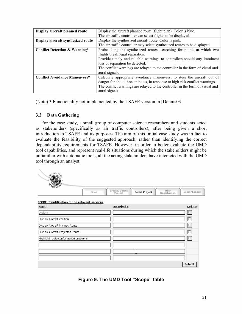
The Table “Scope” (see Figure 9) allows the stakeholder to identify all the services of
the system for which dependability could be of concern. For the system and each identified service, the stakeholder has to provide an identifier (left column), and a brief description (right column).
The Table Frame “Issue” (see Figures 10 and 11) allows the users to specify their
dependability needs by selecting and defining potential issues (failures and/or hazards), their tolerable manifestations, the possible triggering events, and the desired system reactions, for the whole system or a specific service.
3 Applying UMD to build a System Dependability Model This Section shows how UMD can be customized to a specific system/project to obtain a dependability model that can be used as the operational dependability definition of the system. A case study is used for illustration.
3.1 The case study – TSAFE The Tactical Separation Assisted Flight Environment, or TSAFE, is a tool designed to aid air traffic controllers in detecting and resolving short-term conflicts between aircraft.
TSAFE – context and purpose To introduce the case study, we present the following extract from [Dennis03]:
“In today’s Air Traffic Control (ATC) system, air traffic controllers are primarily responsible for maintaining aircraft separation. Controllers accomplish this by surveilling radar data for potential conflicts and issuing clearances to pilots to alter their trajectories accordingly. Ground-based automated tools play only a supportive role in this process.
Under this current system, the airspace within the United States operates at only half its potential capacity. Experience has shown controllers’ workload limits to be the fundamental limiting factor in the current model. (……) exploiting the full airspace capacity requires a new paradigm, the Automated Airspace Concept (AAC).
Under the AAC framework, automated mechanisms would play a primary role in maintaining aircraft separation. Aircraft would remain in direct connection with a round-based automated system, which would transmit conflict alerts and air traffic control clearances via a persistent two-way data link. By shifting much of the responsibility of aircraft separation from controllers to automated systems, AAC will allow controllers to focus more on long-term strategic traffic management, and thereby allow for a safe increase in the volume of aircraft per sector.
The role of TSAFE is as an independent monitor of this AAC Computing System. It is to act as a reliable safety net—a last line of defense against inevitable imperfections in the AAC model. Its job is to probe for short-term conflicts and issue avoidance maneuvers
19

accordingly. As an independent monitor, it must sit outside of the primary system, on separate hardware, and on a separate software process, yet be privy to the same data as the AAC.
TSAFE differs in purpose and functionality from the existing conflict avoidance systems CTAS and TCAS. Whereas CTAS performs long-term conflict prediction on the order of 20-40 minutes ahead, and whereas TCAS detects conflicts only seconds away, TSAFE is intended to detect conflicts somewhere between 3 and 7 minutes in the future. Because TCAS operates on the order of seconds, it only considers aircraft state information–velocities, headings, altitudes, etc. TSAFE and CTAS, on the other hand, must also take intent information into account, including flight routes, cruise altitudes, and cruise speeds. But due to TSAFE’s shorter time horizon, its algorithms must be simpler and less computationally intensive than those of CTAS”.
TSAFE – main functions
TSAFE provides the air traffic controller with a graphical representation of the flight conditions (position, planned route, forecast route) and of the status (conformance or not conformance with planned route) of the flights within a selected geographical area. A snapshot of the TSAFE display is given in Figure 11.
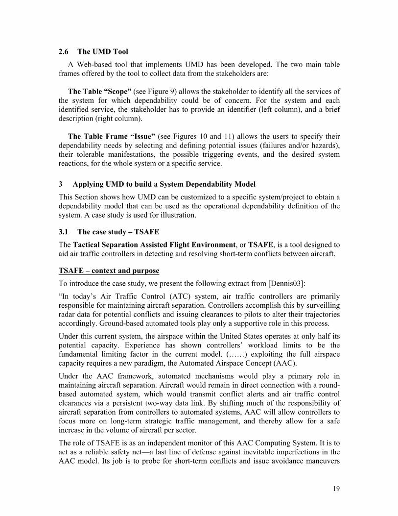
Figure 11 – TSAFE display - example The main functionalities provided by TSAFE are described in the following table: Display current aircraft position and signal route conformance
Display a dot on the map to show current aircraft position. The A/C dot color is either white/red/yellow, depending on conformance/non-conformance/absence of planned route (flight plan). The air traffic controller can select flights to be displayed and the conformance parameters.
20
Display aircraft planned route Display the aircraft planned route (flight plan). Color is blue. The air traffic controller can select flights to be displayed.
Display aircraft synthesized route Display the synthesized aircraft route. Color is pink. The air traffic controller may select synthesized routes to be displayed
Conflict Detection & Warning* Probe along the synthesized routes, searching for points at which two flights break legal separation. Provide timely and reliable warnings to controllers should any imminent loss of separation be detected. The conflict warnings are relayed to the controller in the form of visual and aural signals.
Conflict Avoidance Maneuvers* Calculate appropriate avoidance maneuvers, to steer the aircraft out of danger for about three minutes, in response to high-risk conflict warnings. The conflict warnings are relayed to the controller in the form of visual and aural signals.
(Note) * Functionality not implemented by the TSAFE version in [Dennis03]
3.2 Data Gathering For the case study, a small group of computer science researchers and students acted
as stakeholders (specifically as air traffic controllers), after being given a short introduction to TSAFE and its purposes. The aim of this initial case study was in fact to evaluate the feasibility of the suggested approach, rather than identifying the correct dependability requirements for TSAFE. However, in order to better evaluate the UMD tool capabilities, and represent real-life situations during which the stakeholders might be unfamiliar with automatic tools, all the acting stakeholders have interacted with the UMD tool through an analyst.
Figure 9. The UMD Tool “Scope” table
21
UMD has been applied in two main steps: 1. Scope definition: by analyzing the already available functional requirements, all
the stakeholders, working together and supported by the analyst, have selected the TSAFE main services for which they believed dependability could be relevant. The resulting four services are shown in the scope table (Figure 9).
2. Table filling: each stakeholder, always supported by the analysts, and guided by the structure provided by the tool, has filled as many tables as necessary to define her/his dependability needs (see Figures 10 and 11).
As already discussed in Section 2.3, in this process, the UMD Software component provided a useful guidance to the stakeholder: The stakeholder has in fact used the characterization already available (possibly introduced by other stakeholders using the tool earlier), or, whenever necessary, has extended it with his/her own definitions. The characterizations of the Software component obtained for TSAFE (reconciled among the different stakeholders) are summarized in the Table 1.
Table 1. UMD Software component for TSAFE
Failure characterization: Failure Impact over Availability:
• Stopping failure: failure makes system or service unusable (unfit for use). • Non-Stopping failure: failure does not make system or service unusable.
Failure Types: • Accuracy failure: data is not displayed as required (position, color, etc.). • Throughput failure: system cannot handle the desired number of flights. • Response time failure: system reacts too slowly to a user input. • Other failures: any other failure.
Failure Severity: • High severity: failure with a major impact on the utility of the system for the
operator. • Low severity: failure with a minor impact on the utility of the system for the
operator. Hazard characterization:
• Hazards to People & Properties: state of the system that can lead to catastrophic consequences on people and properties.
• Hazard to Properties Only: state of the system that can lead to catastrophic consequences on properties only (no people affected).
Event characterization: • Adverse Condition: any external event that may have an actual or potential harmful
effect on the system, e.g., broken network connection, un-natural load peaks, etc. • Attack: any intentional action carried on against the system, e.g., logical breaches,
data accesses, denial of service attacks, etc. Measure characterization:
• Time-based probabilistic measure: probability of Occurrence of the issue in the next hour.
Reaction characterization: • Reaction Types: see ones in Section 2.5.
22
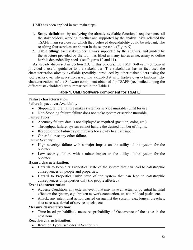
As examples of the collected data, we describe two of the tables filled by the stakeholders.
Figure 10 shows an example of an issue not related to external event. The stakeholder signals a potential failure for the service display aircraft position: aircraft dot is not displayed although the flight is selected. This is an Accuracy failure, a Non-Stopping failure, and a High Severity one, given that has a high impact on the utility of the service. For the stakeholder, this failure is also a hazard (of the type People & Property), given that he thinks he could miss spotting a plane on a dangerous path. In order to be more confident on the system, the stakeholder then asks for the introduction of a warning service, advising in case of mismatch between the number of selected flights and the number of displayed aircraft dots, and of an alternative service, displaying the ID of a not-conforming flight in an apposite text box. In this way, if the dot is not displayed, the information is conveyed by the system. Finally, the stakeholder thinks the failure should not happen more than once a year (transformed by the analysts into a probability of occurrence in the next hour of 10E-4), and asks for the recovery to be performed within one hour by a technician. If this failure condition last more than one hour, in fact, the stakeholder feels he would be unable to properly perform his duties.
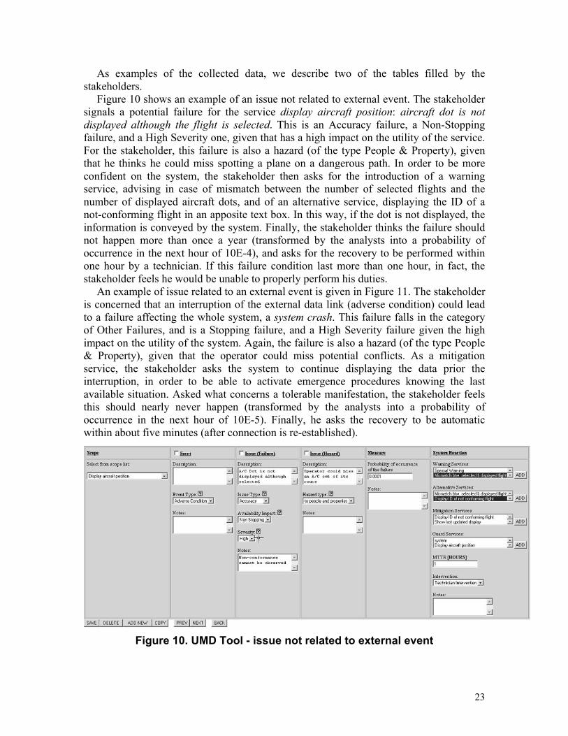
An example of issue related to an external event is given in Figure 11. The stakeholder is concerned that an interruption of the external data link (adverse condition) could lead to a failure affecting the whole system, a system crash. This failure falls in the category of Other Failures, and is a Stopping failure, and a High Severity failure given the high impact on the utility of the system. Again, the failure is also a hazard (of the type People & Property), given that the operator could miss potential conflicts. As a mitigation service, the stakeholder asks the system to continue displaying the data prior the interruption, in order to be able to activate emergence procedures knowing the last available situation. Asked what concerns a tolerable manifestation, the stakeholder feels this should nearly never happen (transformed by the analysts into a probability of occurrence in the next hour of 10E-5). Finally, he asks the recovery to be automatic within about five minutes (after connection is re-established).
Figure 10. UMD Tool - issue not related to external event
23
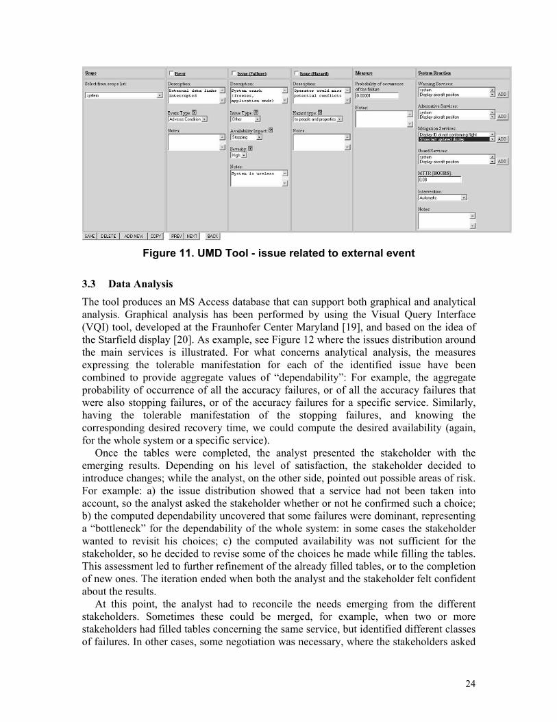
Figure 11. UMD Tool - issue related to external event
3.3 Data Analysis The tool produces an MS Access database that can support both graphical and analytical analysis. Graphical analysis has been performed by using the Visual Query Interface (VQI) tool, developed at the Fraunhofer Center Maryland [19], and based on the idea of the Starfield display [20]. As example, see Figure 12 where the issues distribution around the main services is illustrated. For what concerns analytical analysis, the measures expressing the tolerable manifestation for each of the identified issue have been combined to provide aggregate values of “dependability”: For example, the aggregate probability of occurrence of all the accuracy failures, or of all the accuracy failures that were also stopping failures, or of the accuracy failures for a specific service. Similarly, having the tolerable manifestation of the stopping failures, and knowing the corresponding desired recovery time, we could compute the desired availability (again, for the whole system or a specific service).
Once the tables were completed, the analyst presented the stakeholder with the emerging results. Depending on his level of satisfaction, the stakeholder decided to introduce changes; while the analyst, on the other side, pointed out possible areas of risk. For example: a) the issue distribution showed that a service had not been taken into account, so the analyst asked the stakeholder whether or not he confirmed such a choice; b) the computed dependability uncovered that some failures were dominant, representing a “bottleneck” for the dependability of the whole system: in some cases the stakeholder wanted to revisit his choices; c) the computed availability was not sufficient for the stakeholder, so he decided to revise some of the choices he made while filling the tables. This assessment led to further refinement of the already filled tables, or to the completion of new ones. The iteration ended when both the analyst and the stakeholder felt confident about the results.
At this point, the analyst had to reconcile the needs emerging from the different stakeholders. Sometimes these could be merged, for example, when two or more stakeholders had filled tables concerning the same service, but identified different classes of failures. In other cases, some negotiation was necessary, where the stakeholders asked
24
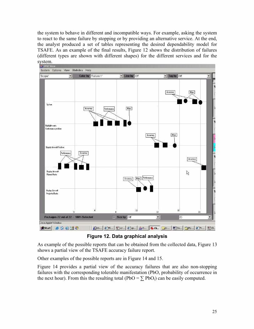
the system to behave in different and incompatible ways. For example, asking the system to react to the same failure by stopping or by providing an alternative service. At the end, the analyst produced a set of tables representing the desired dependability model for TSAFE. As an example of the final results, Figure 12 shows the distribution of failures (different types are shown with different shapes) for the different services and for the system.
Figure 12. Data graphical analysis
As example of the possible reports that can be obtained from the collected data, Figure 13 shows a partial view of the TSAFE accuracy failure report.
Other examples of the possible reports are in Figure 14 and 15.
Figure 14 provides a partial view of the accuracy failures that are also non-stopping failures with the corresponding tolerable manifestation (PbO, probability of occurrence in the next hour). From this the resulting total (PbO = ∑ PbOi) can be easily computed.
25

Figure 13. TSAFE Failure Report (Accuracy failures only)
Figure 14. TSAFE Failure Report (Accuracy & Non stopping failures)
26
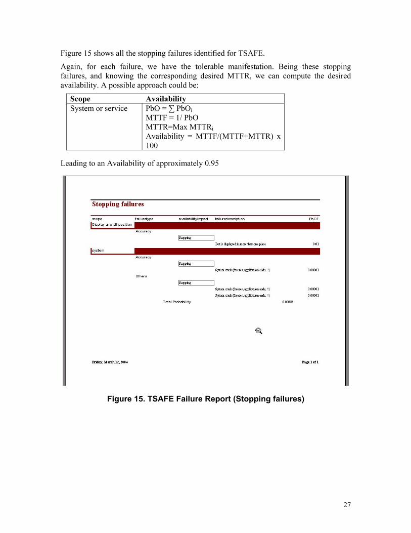
Figure 15 shows all the stopping failures identified for TSAFE.
Again, for each failure, we have the tolerable manifestation. Being these stopping failures, and knowing the corresponding desired MTTR, we can compute the desired availability. A possible approach could be:
Scope Availability System or service PbO = ∑ PbOi
MTTF = 1/ PbO MTTR=Max MTTRi Availability = MTTF/(MTTF+MTTR) x 100
Leading to an Availability of approximately 0.95
Figure 15. TSAFE Failure Report (Stopping failures)
27
4 Formalizing the UMD application process
Requirements elicitation and definition for a system can be performed in many different ways, depending on the system application domain, but also on the specific needs and experience of the users and developers. Regardless of the particular process, UMD can play a valuable role for eliciting and specifying dependability requirements. However, depending on the specific process, the model could be applied and used in different ways. In the following, we introduce and discuss some issues that have to be taken into account while applying the UMD in a real context. In particular, we consider both single-stakeholder and the multiple-stakeholder scenarios.
4.1 The single-stakeholder scenario The UMD application process for the single-stakeholder scenario is based on a set of
assumptions about the surrounding process:
• The stakeholder already has a set of functional requirements defining the system;
• The stakeholder has some dependability needs (possibly, not yet clearly defined);
• The stakeholder will interact with the UMD tool through an analyst.
Different assumptions can, in fact, lead to different application scenarios. For example, if we had assumed that the functional requirements have not been gathered yet, we could have integrated UMD within the requirements elicitation process, to discuss dependability needs while collecting functional requirements.
UMD is applied according to the following steps:
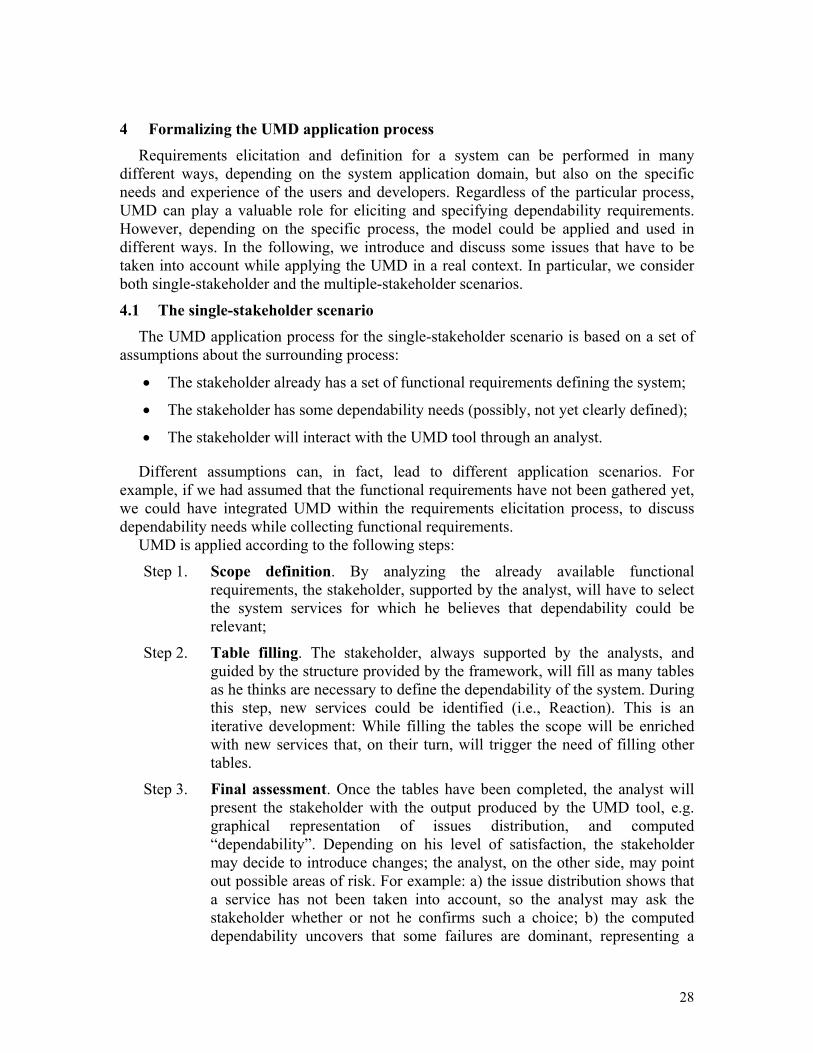
Step 1. Scope definition. By analyzing the already available functional requirements, the stakeholder, supported by the analyst, will have to select the system services for which he believes that dependability could be relevant;
Step 2. Table filling. The stakeholder, always supported by the analysts, and guided by the structure provided by the framework, will fill as many tables as he thinks are necessary to define the dependability of the system. During this step, new services could be identified (i.e., Reaction). This is an iterative development: While filling the tables the scope will be enriched with new services that, on their turn, will trigger the need of filling other tables.
Step 3. Final assessment. Once the tables have been completed, the analyst will present the stakeholder with the output produced by the UMD tool, e.g. graphical representation of issues distribution, and computed “dependability”. Depending on his level of satisfaction, the stakeholder may decide to introduce changes; the analyst, on the other side, may point out possible areas of risk. For example: a) the issue distribution shows that a service has not been taken into account, so the analyst may ask the stakeholder whether or not he confirms such a choice; b) the computed dependability uncovers that some failures are dominant, representing a
28

“bottleneck” for the dependability of the whole system: maybe the stakeholder wants to revisit his choices; c) the computed availability may be not sufficient for the stakeholder, so he could decide to revise some of the choices that he made while filling the tables. Such an assessment could lead to further refinement of the already filled tables, or to the need of filling new ones. The iteration will eventually end when both the analyst and the stakeholder feel confident about the results.
4.2 The multiple-stakeholder scenario There are many ways to integrate multiple stakeholders. A possible scenario is based
on some assumptions about the surrounding process:
• Each stakeholder has gone through the process described in the previous section without interacting with the other stakeholders;
• Negotiation happens only after each stakeholder has stated his/her requirements.
UMD is applied according to the following steps:
Step 1. Requirements gathering from each stakeholder. The analyst will go through the process described in previous Section with each stakeholder separately. At the end of this step, the analyst will have of set of tables for each stakeholder, specifying the desired requirements;
Step 2. Requirements merging and conflict detection. During the previous step, each stakeholder has expressed his/her own needs for dependability. At this point, the analyst has to merge these different needs, while identifying possible conflicts.
Step 3. Negotiation among the stakeholders. Once the areas of possible conflicts have been identified, the analyst needs to focus on the corresponding requirements to verify whether a conflict really exists, or if the requirements could be merged as they are. For example, two or more stakeholders could have filled tables concerning the same service, but identified different classes of failures. In this case the requirements could be merged. There could be cases, however, where the stakeholders may ask the system to behave in different and incompatible ways. For example, asking the system to react to the same failure by stopping or by providing an alternative service. At the end of this step, the analyst will have a set of requirements (i.e. tables) representing the desired dependability of all the stakeholders.
Step 4. Three-way negotiation: stakeholders, analyst and developers. It is important to note that even though reconciliation has been achieved among all the stakeholders, and all the different requirements have been merged, it may still be necessary to revise the previous choices. It is possible that the evolved dependability requirements may not be achievable because of constraints such as limited recourses (time or money) or the unavailability of technology. In this case we need a new and extended negotiation
29
between the stakeholders and the developers, with the analyst acting as mediator. During this negotiation, for example, some or all of the stakeholders may have to adjust their requirements in order for the new system to be feasible, or, simply, to be less expensive.
For all these negotiation activities, the analyst may benefit from the support of negotiation-oriented models, such as Win-Win [Boehm01a, Boehm01b, Grünbacher01, Grünbacher00].
Finally, the outcome of applying the UMD consists of a dependability model of the system, the set of requirements that make the system more dependable for the stakeholders (dependability requirements):
1) A set of non-functional requirements (i.e., the relevant failures and the corresponding measure that have been specified for the services and the system).
2) A set of extended functional requirements (i.e., the initial functional requirements enriched with the new services that have been identified).
5 Conclusions and future work Although only one case study was adopted, the results have increased our confidence
that UMD will be able to achieve our initial goals:
• Establishing a common framework to discuss a variety of dependability attributes in common terms: scope, measure and expected system reaction.
• Defining dependability needs and making them measurable.
• Helping stakeholders to better understand their needs, the interactions among the different dependability attributes, and how to set the corresponding values.
Of course, more empirical assessments are necessary, and these are at the top of the list of our planned future activities: Empirical Assessment. Verify utility of UMD for requirements elicitation/discovery. Investigate how useful UMD (and associated tool) can be within the area of requirements engineering. Thus, we would like to investigate:
• How to better exploit UMD capabilities within the elicitation/discovery and early
validation activities of requirements engineering. • The value added by the UMD Tool during such activities. • Which interface for the UMD tool is best suitable to involve the stakeholders and
support the elicitation process.
UMD Extension. We want extend the support that UMD can provide to stakeholders, by encompassing more experience-based capabilities. For example, the ability of suggesting to stakeholders, once a potential issue has been identified for a specific
30
service, the most appropriate measurement models, the most common system reactions and possible external events that could cause it.
Combine UMD and Win-Win Models capabilities. Easy Win-Win [Boehm01 a, Boehm01 b, Grünbacher01, Grünbacher00] supports the negotiation with the stakeholders and aims at categorizing and organizing the negotiation results.
Priorities and categories coming from Easy Win-Win may add extra value to UMD; at the same time, the new functional and non-functional requirements acquired by applying UMD may enrich the “solution space” upon which Win-Win is applied, so enhancing the overall outcome.
6 References [1] Avizienis A., Laprie J.C., Randell B., Fundamental Concepts of Dependability, Research Report N01145, LAAS-CNRS, April 2001. [2] Basili, V., Donzelli, P., Asgari, S. Modelling Dependability The Unified Model of Dependability, University of Maryland Tech. Report, April 2004 (to appear). [3] Boehm, B., Huang L., Jain A., Madachy R., The Nature of Information System Dependability – A Stakeholder/Value Approach - USC Technical Report November 2003. [4] Bruegge B. Dutoit A. H., Object oriented Software Engineering, Prentice Hall, 2004. [5] Dennis G. TSAFE: Building a Trusted Computing Base for Air Traffic Control Software (MSc Thesis), January 2003. [6] Huynh, D., Zelkowitz M., Basili V., Rus I., Modeling dependability for a diverse set of stakeholders, Distributed Systems and Networks 2003, San Francisco, CA, June 2003. [7] International Federation for Information Processing (IFIP WG-10.4), www.dependability.org. [8] Laprie Jean-Claude, Dependability: Basic Concepts and Terminology, Dependable Computing and Fault Tolerance, Vienna, Austria, Springer-Verlag, 1992. [9] Melhart Bonnie, Stephanie White, Issues in defining, analyzing, refining, and specifying system dependability requirements, IEEE Conference on the Engineering of Computer Based Systems, April 2000. [10] Moteff, C. Copeland, J. Fisher, Critical Infrastructures: What Makes an Infrastructure Critical?, Report for Congress RL31556, The Library of Congress, 21 January 2003. [11] Randel B., Dependability, a unifying concepts, Proceedings of Computer Security, Dependability and Assurance: from needs to solutions, York, UK & Williamsburg, VA, USA, July & November 1998. [12] Rus, I., Basili V., Zelkowitz M., Boehm B., Empirical evaluation techniques and methods used for achieving and assessing high dependability, Workshop on dependability benchmarking, DC, June, 2002. [13] Sommerville, I., Software Engineering, Fourth-Edition, Addison Wesley, UK, 1992.
31
[14] The European Initiative on Dependability: towards dependable Information, http://deppy.jrc.it. [15] U.S. The National Strategy to Secure Cyberspace, February 2003; http://www.whitehouse.gov/pcipb. [16] Wenger A., Metzger J., Dunn M. (edited by) International CIIP Handbook, ETH, Swiss Federal Institute of Technology Zurich, 2004; www.isn.ethz.ch/crn/_docs/ CIIP_Handbook_2004_web.pdf. [17] Boehm B., Egyed A., Kwan J., Shah A., Madachy R., Using the win-win spiral model: a case study, IEEE Computer, July 1998. [18] Alexander I., Robertson S., Understanding project sociology by modeling stakeholders, IEEE Software, January 2004. [19] Lindvall M, Frey M., Costa P., Tesoriero R., Lessons Learned about Structuring and Describing Experience for Three Experience Bases, Lecture Notes in Computer Science, Vol. 2176, 2001. [20] Jog N, Shneiderman B., Starfield Information Visualization with Interactive Smooth Zooming, University of Maryland Technical Report, College Park MD 20742-3255 USA, 1994 and Proc. of IFIP 2.6 Visual Databases Systems, Lausanne, Switzerland, March 27-29, 1995 Acknowledgements
The authors wish to acknowledge support from the NASA High Dependability Computing Program under cooperative agreement NCC-2-1298
32
Appendix A – Description of the UMD Tool
Getting Started The UMD tool is a web-based tool. The Login Menu is illustrated in Figure 1.
Figure 1: Login Menu
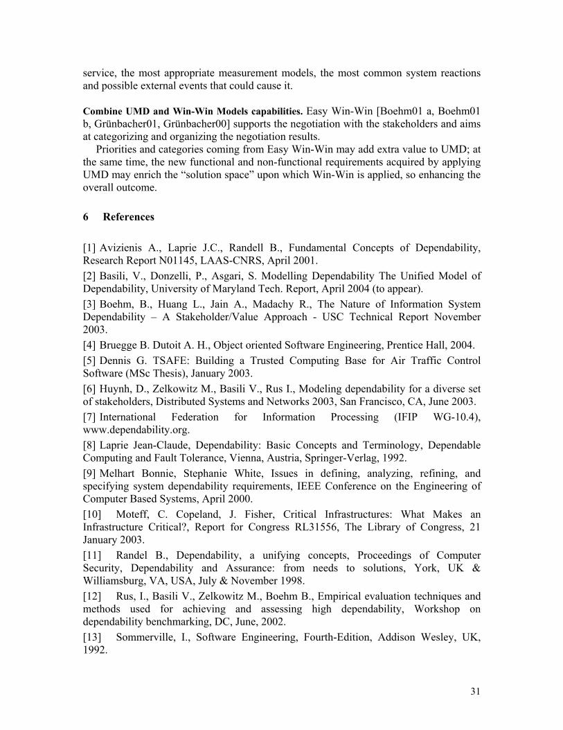
After a successful login, the start menu will appear on the screen
Figure 2: Start Menu
Using this menu, the user can create a new (dependability) model, and delete or select an existing model. Only the system administrator can use the “User Registration” option.
33
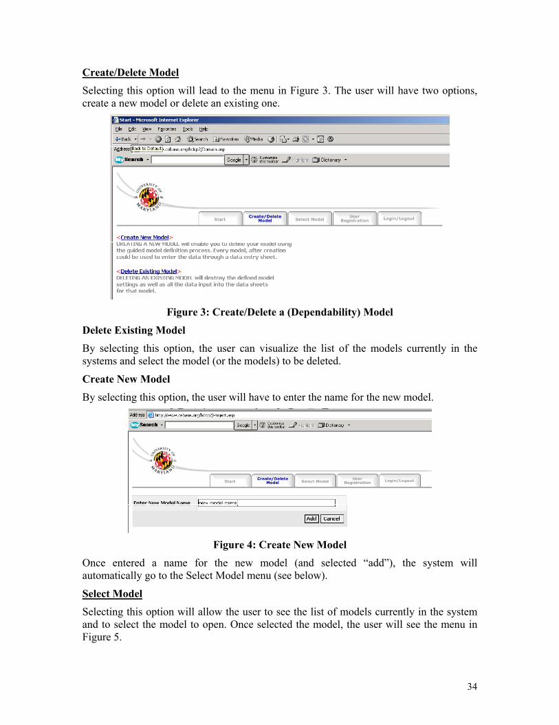
Create/Delete Model
Selecting this option will lead to the menu in Figure 3. The user will have two options, create a new model or delete an existing one.
Figure 3: Create/Delete a (Dependability) Model
Delete Existing Model By selecting this option, the user can visualize the list of the models currently in the systems and select the model (or the models) to be deleted.
Create New Model By selecting this option, the user will have to enter the name for the new model.
Figure 4: Create New Model
Once entered a name for the new model (and selected “add”), the system will automatically go to the Select Model menu (see below).
Select Model Selecting this option will allow the user to see the list of models currently in the system and to select the model to open. Once selected the model, the user will see the menu in Figure 5.
34
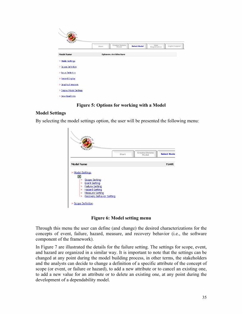
Figure 5: Options for working with a Model
Model Settings
By selecting the model settings option, the user will be presented the following menu:
Figure 6: Model setting menu
Through this menu the user can define (and change) the desired characterizations for the concepts of event, failure, hazard, measure, and recovery behavior (i.e., the software component of the framework).
In Figure 7 are illustrated the details for the failure setting. The settings for scope, event, and hazard are organized in a similar way. It is important to note that the settings can be changed at any point during the model building process, in other terms, the stakeholders and the analysts can decide to change a definition of a specific attribute of the concept of scope (or event, or failure or hazard), to add a new attribute or to cancel an existing one, to add a new value for an attribute or to delete an existing one, at any point during the development of a dependability model.
35
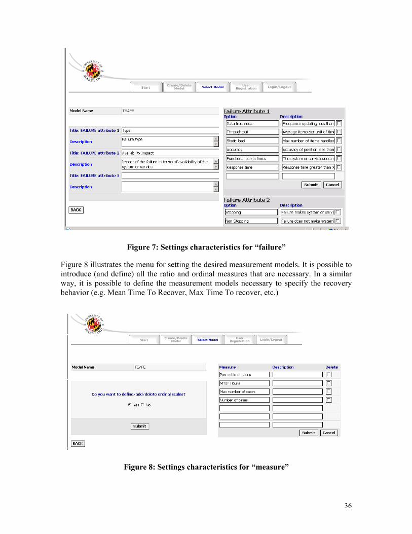
Figure 7: Settings characteristics for “failure”
Figure 8 illustrates the menu for setting the desired measurement models. It is possible to introduce (and define) all the ratio and ordinal measures that are necessary. In a similar way, it is possible to define the measurement models necessary to specify the recovery behavior (e.g. Mean Time To Recover, Max Time To recover, etc.)
Figure 8: Settings characteristics for “measure”
36
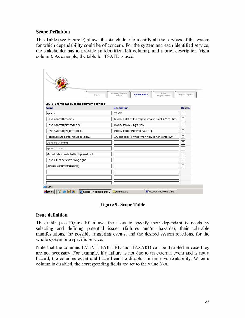
Scope Definition
This Table (see Figure 9) allows the stakeholder to identify all the services of the system for which dependability could be of concern. For the system and each identified service, the stakeholder has to provide an identifier (left column), and a brief description (right column). As example, the table for TSAFE is used.
Figure 9: Scope Table
Issue definition This table (see Figure 10) allows the users to specify their dependability needs by selecting and defining potential issues (failures and/or hazards), their tolerable manifestations, the possible triggering events, and the desired system reactions, for the whole system or a specific service.
Note that the columns EVENT, FAILURE and HAZARD can be disabled in case they are not necessary. For example, if a failure is not due to an external event and is not a hazard, the columns event and hazard can be disabled to improve readability. When a column is disabled, the corresponding fields are set to the value N/A.
37

Figure 8: Table Frame “issue”
In the first column of this table “Scope” the user should select the scope of the issue from the list of scopes introduced when the project was defined.
In the second column “event” the external event causing the issue should be specified. Characteristics of the event should be defined by selecting the appropriate values accordingly to the model settings.
The same applies for the columns “failure” and “hazard”.
38
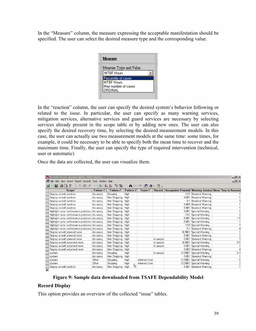
In the “Measure” column, the measure expressing the acceptable manifestation should be specified. The user can select the desired measure type and the corresponding value.
In the “reaction” column, the user can specify the desired system’s behavior following or related to the issue. In particular, the user can specify as many warning services, mitigation services, alternative services and guard services are necessary by selecting services already present in the scope table or by adding new ones. The user can also specify the desired recovery time, by selecting the desired measurement models. In this case, the user can actually use two measurement models at the same time: some times, for example, it could be necessary to be able to specify both the mean time to recover and the maximum time. Finally, the user can specify the type of required intervention (technical, user or automatic)
Once the data are collected, the user can visualize them.
Figure 9: Sample data downloaded from TSAFE Dependability Model
Record Display This option provides an overview of the collected “issue” tables.
39
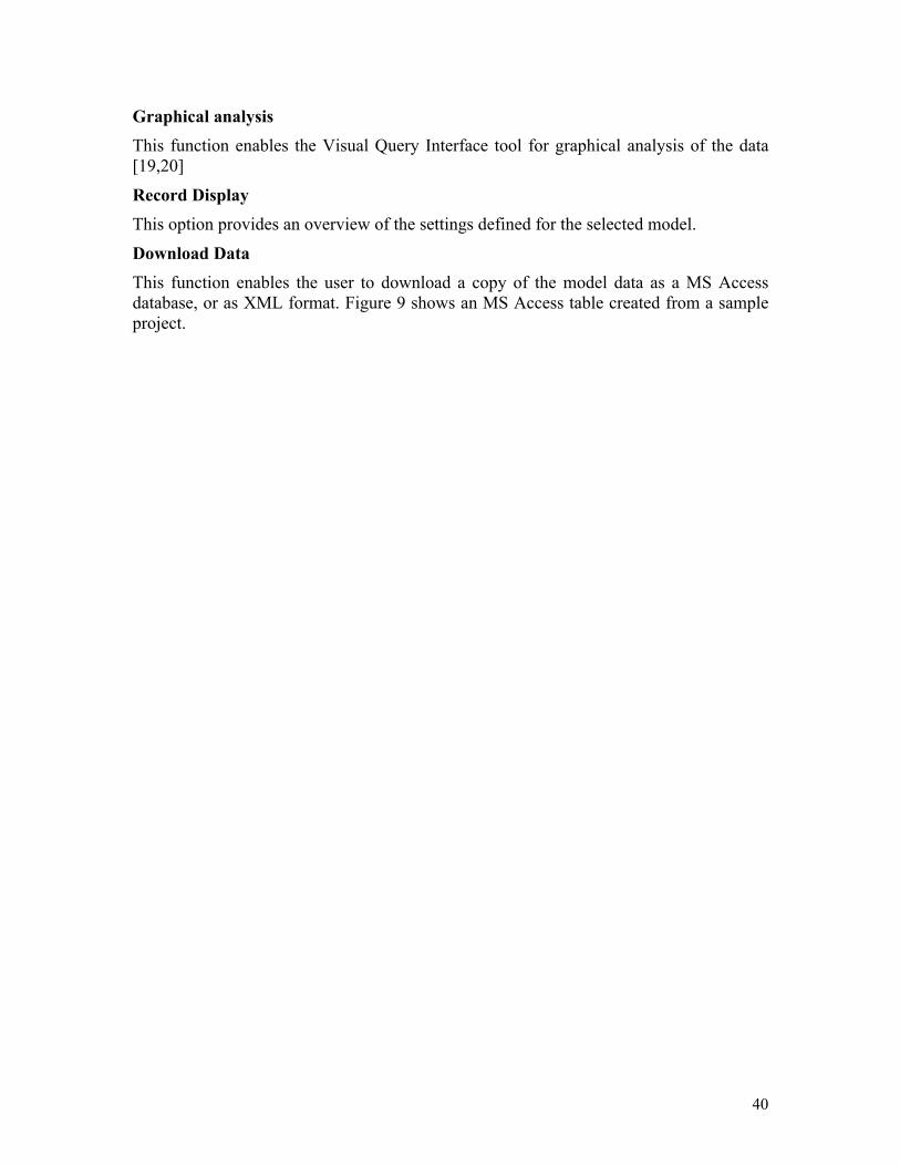
Graphical analysis
This function enables the Visual Query Interface tool for graphical analysis of the data [19,20]
Record Display This option provides an overview of the settings defined for the selected model.
Download Data
This function enables the user to download a copy of the model data as a MS Access database, or as XML format. Figure 9 shows an MS Access table created from a sample project.
40
Related Documents