The Traveler Series: Adventurer RENOGY 30A Flush Mount Charge Controller Manual 2775 E. Philadelphia St., Ontario, CA 91761 1-800-330-8678 Version: 2.3

Welcome message from author
This document is posted to help you gain knowledge. Please leave a comment to let me know what you think about it! Share it to your friends and learn new things together.
Transcript
The Traveler Series: Adventurer
RENOGY 30A Flush Mount Charge Controller Manual
2775 E. Philadelphia St., Ontario, CA 91761
1-800-330-8678
Version: 2.3
1
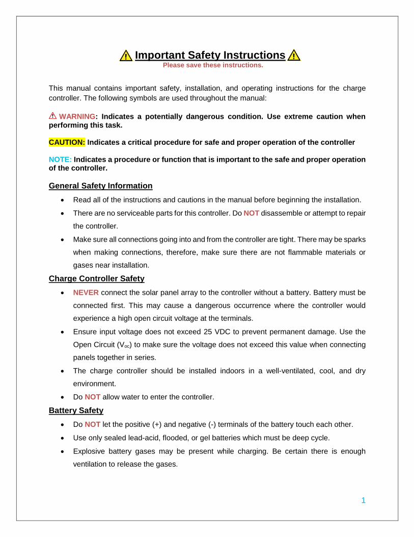
Important Safety Instructions Please save these instructions.
This manual contains important safety, installation, and operating instructions for the charge
controller. The following symbols are used throughout the manual:
WARNING: Indicates a potentially dangerous condition. Use extreme caution when
performing this task. CAUTION: Indicates a critical procedure for safe and proper operation of the controller NOTE: Indicates a procedure or function that is important to the safe and proper operation of the controller.
General Safety Information
Read all of the instructions and cautions in the manual before beginning the installation.
There are no serviceable parts for this controller. Do NOT disassemble or attempt to repair
the controller.
Make sure all connections going into and from the controller are tight. There may be sparks
when making connections, therefore, make sure there are not flammable materials or
gases near installation.
Charge Controller Safety
NEVER connect the solar panel array to the controller without a battery. Battery must be
connected first. This may cause a dangerous occurrence where the controller would
experience a high open circuit voltage at the terminals.
Ensure input voltage does not exceed 25 VDC to prevent permanent damage. Use the
Open Circuit (Voc) to make sure the voltage does not exceed this value when connecting
panels together in series.
The charge controller should be installed indoors in a well-ventilated, cool, and dry
environment.
Do NOT allow water to enter the controller.
Battery Safety
Do NOT let the positive (+) and negative (-) terminals of the battery touch each other.
Use only sealed lead-acid, flooded, or gel batteries which must be deep cycle.
Explosive battery gases may be present while charging. Be certain there is enough
ventilation to release the gases.

2
Be careful when working with large lead acid batteries. Wear eye protection and have
fresh water available in case there is contact with the battery acid.
Over-charging and excessive gas precipitation may damage the battery plates and
activate material shedding on them. Too high of an equalizing charge or too long of one
may cause damage. Please carefully review the specific requirements of the battery used
in the system.
WARNING: Connect battery terminals to the charge controller BEFORE connecting the solar
panel(s) to the charge controller. NEVER connect solar panels to charge controller until the battery
is connected.
3
Table of Contents
General Information ...................................................................................................... 4
Included Components ................................................................................................... 6
Identification of Parts .................................................................................................... 6
Installation ..................................................................................................................... 7
Mounting Recommendations: .................................................................................. 8
Wiring ....................................................................................................................... 10
Operation ..................................................................................................................... 13
Adjustable Parameters ............................................................................................ 14
1. Generated Energy Interface ................................................................................ 14
2. Battery Voltage Interface .................................................................................... 14
3. Battery Temperature Interface ............................................................................ 15
System Status Icons ................................................................................................... 15
System Status Troubleshooting ................................................................................ 15
Maintenance ................................................................................................................ 16
Fusing .......................................................................................................................... 16
Technical Specifications ............................................................................................ 17
Battery Charging Parameters ................................................................................. 17
Dimensions .................................................................................................................. 18
4
General Information
The Adventurer is an advanced charge controller for off-grid solar applications. Integrating highly
efficient PWM charging, this controller increases battery life and improved system performance.
It can be used for 12V battery or battery bank. The controller is embedded with self-diagnostics
and electronic protection functions that prevent damages from installation mistakes or system
faults.
Key Features
Optimized for 12 VDC system voltage
30A charging capacity
LCD screen for displaying system operating information and data.
Full control of parameter settings that can be adjusted.
Sealed, Gel, and Flooded battery option.
4 Stage PWM charging: Bulk, Boost. Float, and Equalization
Temperature compensation and correcting the charging and discharging parameters
automatically, improving battery lifetime.
Protection against: overcharging, overload, short-circuit, and reverse polarity.
Negative ground controller
Specifically designed for RV application and allows for aesthetically clean flush mounting
on walls
Remote temperature compensation compatible
Remote battery voltage sensor compatible
PWM Technology
The Adventurer utilizes Pulse Width Modulation (PWM) technology for battery charging. Battery charging is a current based process so controlling the current will control the battery voltage. For the most accurate return of capacity, and for the prevention of excessive gassing pressure, the battery is required to be controlled by specified voltage regulation set points for Absorption, Float, and Equalization charging stages. The charge controller uses automatic duty cycle conversion, creating pulses of current to charge the battery. The duty cycle is proportional to the difference between the sensed battery voltage and the specified voltage regulation set point. Once the battery reached the specified voltage range, pulse current charging mode allows the battery to react and allows for an acceptable rate of charge for the battery level
Four Charging Stages
The Adventurer has a 4-stage battery charging algorithm for a rapid, efficient, and safe battery charging. They include: Bulk Charge, Boost Charge, Float Charge, and Equalization.
5
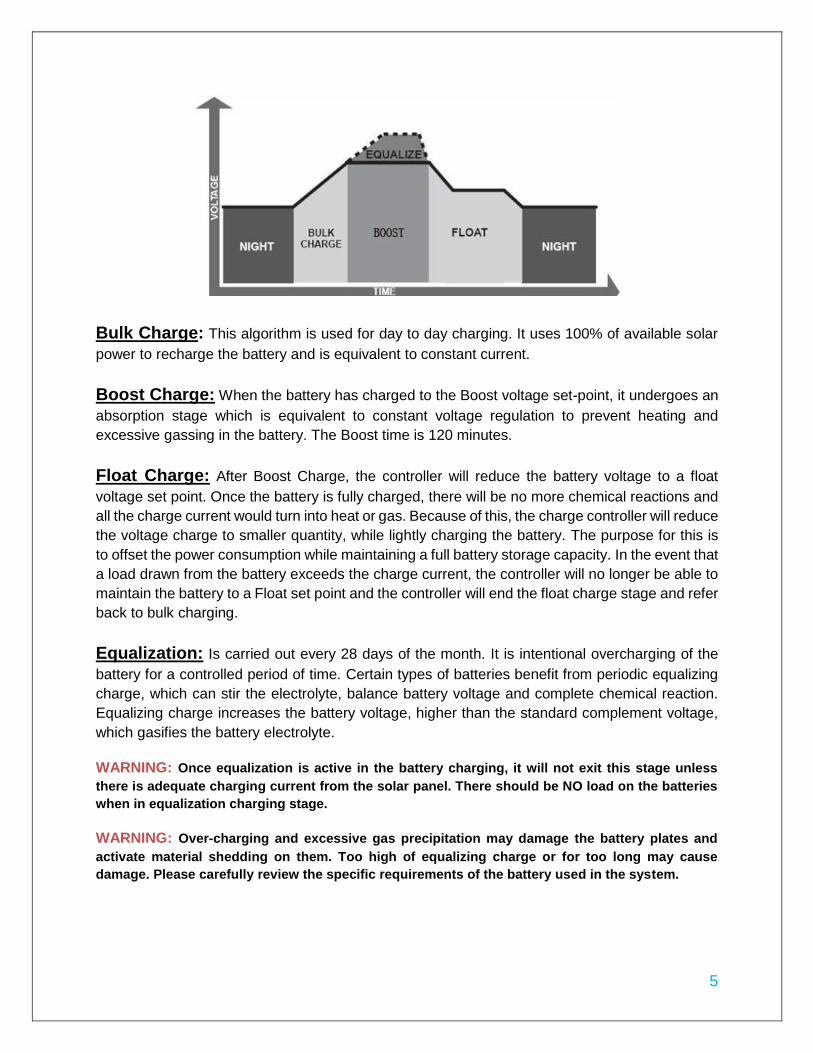
Bulk Charge: This algorithm is used for day to day charging. It uses 100% of available solar
power to recharge the battery and is equivalent to constant current.
Boost Charge: When the battery has charged to the Boost voltage set-point, it undergoes an
absorption stage which is equivalent to constant voltage regulation to prevent heating and
excessive gassing in the battery. The Boost time is 120 minutes.
Float Charge: After Boost Charge, the controller will reduce the battery voltage to a float
voltage set point. Once the battery is fully charged, there will be no more chemical reactions and
all the charge current would turn into heat or gas. Because of this, the charge controller will reduce
the voltage charge to smaller quantity, while lightly charging the battery. The purpose for this is
to offset the power consumption while maintaining a full battery storage capacity. In the event that
a load drawn from the battery exceeds the charge current, the controller will no longer be able to
maintain the battery to a Float set point and the controller will end the float charge stage and refer
back to bulk charging.
Equalization: Is carried out every 28 days of the month. It is intentional overcharging of the
battery for a controlled period of time. Certain types of batteries benefit from periodic equalizing
charge, which can stir the electrolyte, balance battery voltage and complete chemical reaction.
Equalizing charge increases the battery voltage, higher than the standard complement voltage,
which gasifies the battery electrolyte.
WARNING: Once equalization is active in the battery charging, it will not exit this stage unless
there is adequate charging current from the solar panel. There should be NO load on the batteries
when in equalization charging stage.
WARNING: Over-charging and excessive gas precipitation may damage the battery plates and
activate material shedding on them. Too high of equalizing charge or for too long may cause
damage. Please carefully review the specific requirements of the battery used in the system.

6
Included Components NOTE: The Adventurer is shipped with its own screws for flush mounting.
Remote Temperature Sensor (TS-R): Measures the temperature
at the battery and uses this data for very accurate temperature
compensation. The sensor is supplied with a 6.6ft cable length that
connects to the charge controller. (Figure 1)
NOTE: The Adventurer comes equipped with a temperature sensor,
but it is ONLY for the charge controller’s temperature compensation,
not the battery’s temperature compensation.
Remote Battery Voltage Sensor (RBVS): Measures battery voltage accurately. The voltage detected at the battery terminals on the controller may differ from the real battery voltage due to the connection and cable resistance. Therefore this sensor, though not required, is recommended for best performance. (Figure 2)
Adventurer Surface Mount Attachment: The Renogy Adventurer Surface Mount will give you the option to mount the charge controller to any flat surface; circumventing the flush mount option.
Figure 1
Figure 2
Figure 3

7
Identification of Parts
Key Parts
1. Select Button
2. Enter Button
3. Liquid Crystal Display (LCD)
4. PV terminals
5. Battery Terminals
6. Remote Temperature Sensor Terminal (optional accessory)
7. Remote Battery Voltage Sensor Terminal (optional accessory)
Installation
WARNING: Connect battery terminal wires to the charge controller FIRST then connect the solar panel(s) to the charge controller. NEVER connect solar panel to charge controller before the battery.
3
77
6
1
4 5
2
8
CAUTION: Do not over-torque or over tighten the screw terminals. This could potentially break
the piece that holds the wire to the charge controller. CAUTION: Refer to the technical specifications for max wire sizes on the controller and for the maximum amperage going through wires.
Mounting Recommendations: WARNING: Never install the controller in a sealed enclosure with flooded batteries. Gas can accumulate and there is a risk of explosion.
The Adventurer is designed for flush mounting on a wall. It consists of a face plate with projecting terminals on the backside for connecting the battery bank, panels, and optional sensors for accurate battery voltage sensing and battery temperature compensation. If utilizing the wall mount, then the wall will be required to be cut to accommodate the projecting terminals on the backside. Make sure that the pocket of the wall cut leaves enough space to not damage the terminals when the Adventurer is being pushed back into the cut out section of the wall. The front of the Adventurer will serve as a heat sink, therefore it is important to ensure that the mounting location is not near any heat generating sources and ensure that there is proper airflow across the faceplate of the Adventurer to remove the heat dissipated from the surface.
1. Choose Mounting Location—place the controller on a vertical surface protected from
direct sunlight, high temperatures, and water. Make sure there is good ventilation.
2. Check for Clearance—verify that there is sufficient room to run wires, as well as
clearance above and below the controller for ventilation. The clearance should be at least
6 inches (150mm).
3. Cut out Wall section—the recommended wall size to be cut should follow the inner
protruding part of the charge controller while being careful not to go past the mounting
holes. The depth should be at least 1.7 inches (43mm).
4. Mark Holes
5. Drill Holes
NOTE: The Adventurer comes equipped with screws for wall mounting. If they are not
suitable try using Pan Head Phillips Screw 18-8 Stainless Steel M3.9 Size 25mm
length screws.
6. Secure the charge controller.

9
The charge controller can also be mounted on a flat surface using the Adventurer Surface Mount Attachment. In order to properly mount the charge controller, steps 1 and 2 for the flush mount option can be followed. However, there is no need to cut a section of the wall considering the charge controller can now be mounted on a flat surface using the attachment. Mark and drill holes using the four pan head Phillips screws that are provided specifically for the surface mount option.
10
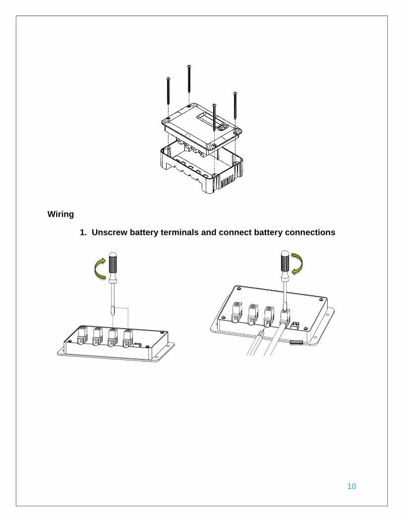
Wiring
1. Unscrew battery terminals and connect battery connections

11
2. Unscrew PV terminals and connect PV connections
12
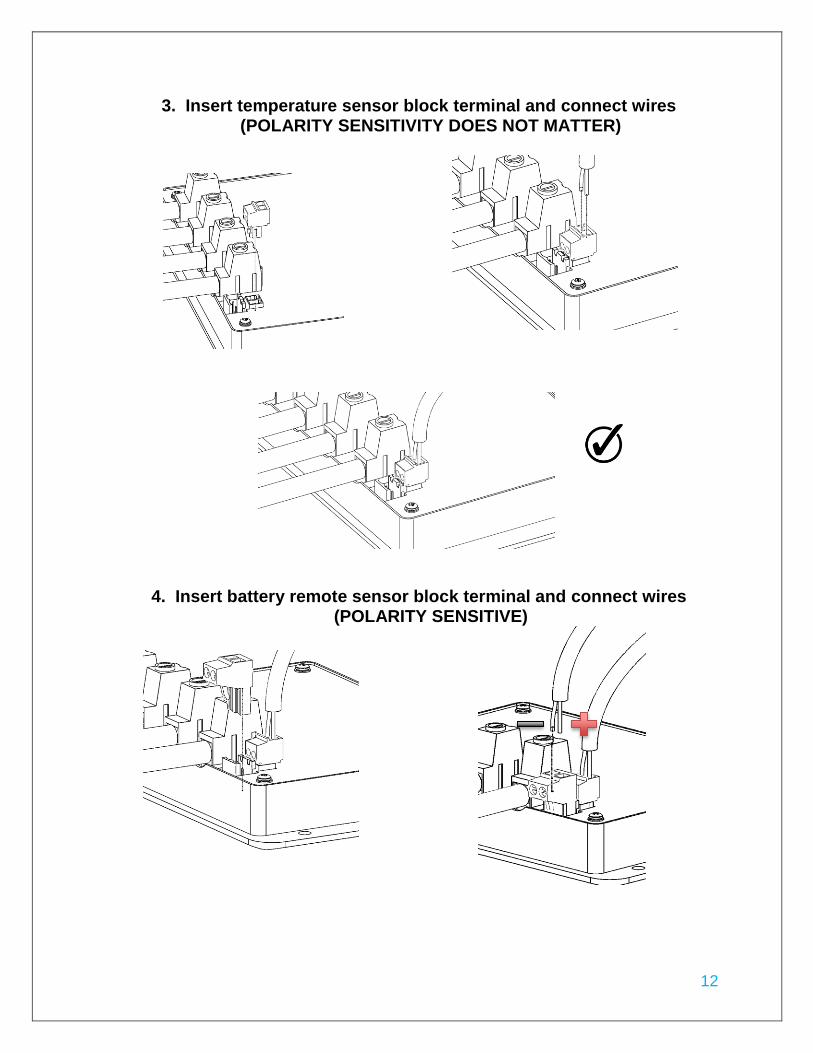
3. Insert temperature sensor block terminal and connect wires (POLARITY SENSITIVITY DOES NOT MATTER)
4. Insert battery remote sensor block terminal and connect wires (POLARITY SENSITIVE)

13
Operation
After connecting the battery to the charge controller, the controller will turn on automatically. Assuming normal operation, the charge controller will cycle through different display. They are as follows:
Parameter Display
PV Array Voltage PV 0.0 V
Charging Current PV 0.0 A
Generated Energy PV 0.0 kWh
Battery Voltage BATT 0.0 V
Battery SOC% BATT 0.0 %

14
Temperature BATT 0.0 F°
The Adventurer is an easy to use controller requiring minimal maintenance. The user is able to adjust some parameters based on the display screen. The user can manually cycle through the display screens by using the “SELECT” and “ENTER” buttons
Adjustable Parameters Simply hold the “ENTER” button for approximately 5 seconds until the display flashes. Once flashing, then press “SELECT” until the desired parameter is reached and press “ENTER” one more time to lock in the parameter.
1. Generated Energy Interface
The user is able to reset the current power generation (kWh) back to 0 kWh.
2. Battery Voltage Interface
In this interface, the user is able to select which type of battery is connected to the charge controller. Choose from Sealed, Gel, or Flooded batteries.
SELECT Cycles forwards through the different display screens.
ENTER Cycles backwards through the different select screens & Customize some parameters on the charge controller
15
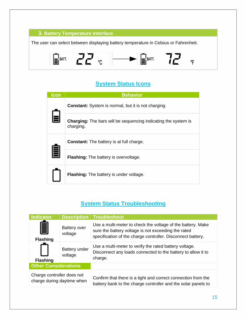
3. Battery Temperature Interface
The user can select between displaying battery temperature in Celsius or Fahrenheit.
System Status Icons
Icon Behavior
Constant: System is normal, but it is not charging
Charging: The bars will be sequencing indicating the system is charging.
Constant: The battery is at full charge.
Flashing: The battery is overvoltage.
Flashing: The battery is under voltage.
System Status Troubleshooting
Indicator Description Troubleshoot
Flashing
Battery over
voltage
Use a multi-meter to check the voltage of the battery. Make
sure the battery voltage is not exceeding the rated
specification of the charge controller. Disconnect battery.
Flashing
Battery under
voltage
Use a multi-meter to verify the rated battery voltage.
Disconnect any loads connected to the battery to allow it to
charge.
Other Considerations
Charge controller does not
charge during daytime when
Confirm that there is a tight and correct connection from the
battery bank to the charge controller and the solar panels to

16
the sun is shining on the
solar panels.
the charge controller. Use a multi-meter to check if the polarity
of the solar modules have been reversed on the charge
controller’s solar terminals.
Everything is connected
correctly, but the LCD on the
controller does not turn on
Check the rated battery voltage. The LCD will not display on
the charge controller unless there is at least 9V coming from
the battery bank.
Maintenance
For best controller performance, it is recommended that these tasks be performed from time to
time.
1. Check that controller is mounted in a clean, dry, and ventilated area.
2. Check wiring going into the charge controller and make sure there is no wire damage or
wear.
3. Tighten all terminals and inspect any loose, broken, or burnt up connections
4. Make sure readings in the LCD and LED are consistent.
Fusing Fusing is a recommendation in PV systems to provide a safety measure for connections going
from panel to controller and controller to battery. Remember to always use the recommended
wire gauge size based on the PV system and the controller.
NEC Maximum Current for different Copper Wire Sizes
AWG 16 14 12 10 8 6 4 2 0 Max.
Current 10A 15A 20A 30A 55A 75A 95A 130A 170A
Fuse from Controller to Battery
Controller to Battery Fuse = Current Rating of Charge Controller
Ex. FM30ACC = 30A fuse from Controller to Battery
Fuse from Solar Panel(s) to Controller

17
Technical Specifications
Description Parameter Nominal Voltage 12 VDC
Rated Charge Current 30A
Max. PV Input Voltage 25 VDC
Equalization Voltage Sealed: 14.6 V; Gel: None; Flooded: 14.8 V
Boost Voltage Sealed: 14.4 V; Gel: 14.2 V; Flooded: 14.6 V
Float Voltage 13.8 V
Under Voltage 12 V
Self-consumption ≤13mA
Temperature Compensation Coefficient
-3mV/℃/2V
Operating Temperature -25℃ to +55℃ | -13oF to 131oF
Storage Temperature -35℃ to +80℃ | -31oF to 176oF
Enclosure IP20
Terminals Up to #4 AWG
Weight 0.6 lbs.
Battery Charging Parameters Battery GEL SEALED FLOODED
High Voltage
Disconnect 16 V 16 V 16 V
Charging Limit Voltage 15.5 V 15.5 V 15.5 V
Over Voltage
Reconnect 15 V 15 V 15 V
Equalization Voltage ----- 14.6 V 14.8 V
Boost Voltage 14.2 V 14.4 V 14.6 V
Float Voltage 13.8 V 13.8 V 13.2 V
Boost Return Voltage 13.2 V 13.2 V 13.2 V
Low Voltage Reconnect 12.6 V 12.6 V 12.6 V
Ex. 200W; 2 X 100 W panels
Parallel
Total Amperage = Isc1 + Isc2 = 5.75A + 5.75A * 1.56
Fuse = minimum of 11.5 * 1.56 = 17.94 = 18A fuse

18
Under Voltage Recover 12.2 V 12.2 V 12.2 V
Under Voltage Warning 12 V 12 V 12 V
Low Voltage Disconnect 11.1 V 11.1 V 11.1 V
Discharging Limit
Voltage 10.8 V 10.8 V 10.8 V
Equalization Duration ----- 2 hours 2 hours
Boost Duration 2 hours 2 hours 2 hours
Dimensions

19
Related Documents