The Transport Layer Chapter 6

Welcome message from author
This document is posted to help you gain knowledge. Please leave a comment to let me know what you think about it! Share it to your friends and learn new things together.
Transcript
The Transport Layer
Chapter 6

The Transport Service
• Services Provided to the Upper Layers
• Transport Service Primitives
• Berkeley Sockets
• An Example of Socket Programming:
– An Internet File Server

Services Provided to the Upper Layers
The network, transport, and application layers.

Transport Service Primitives
The primitives for a simple transport service.
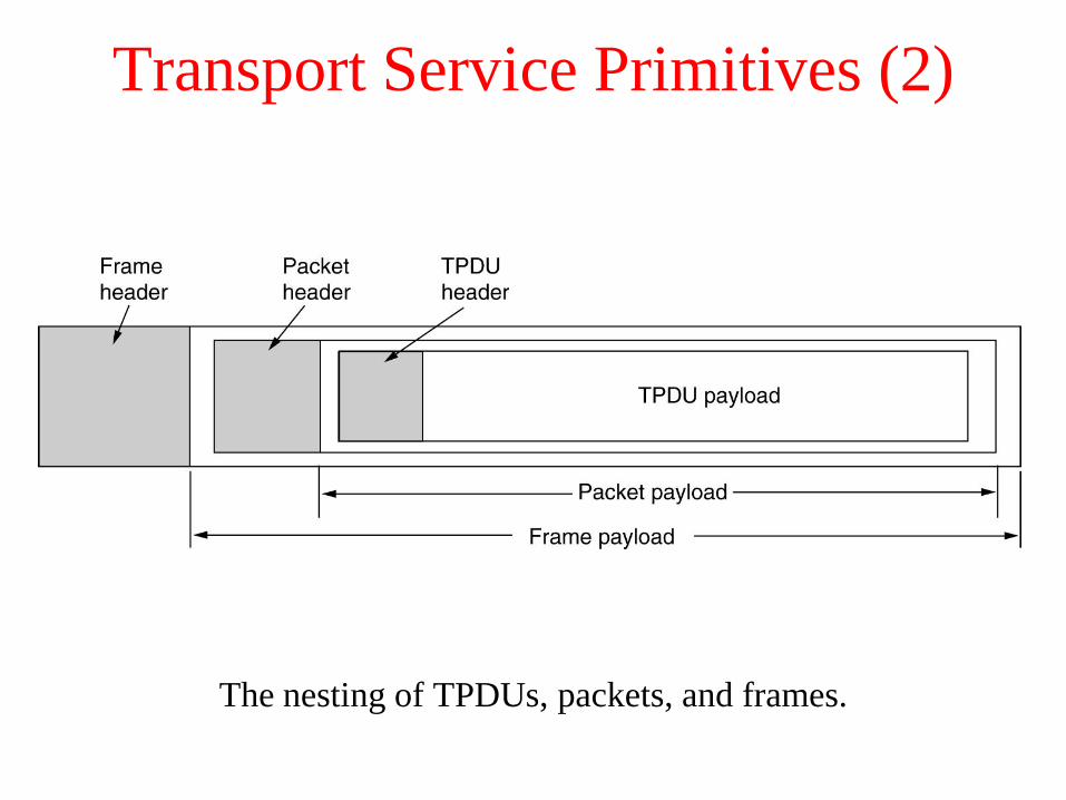
Transport Service Primitives (2)
The nesting of TPDUs, packets, and frames.

Transport Service Primitives (3)
A state diagram for a simple connection management scheme.
Transitions labeled in italics are caused by packet arrivals. The
solid lines show the client's state sequence. The dashed lines show
the server's state sequence.

Berkeley Sockets
The socket primitives for TCP.
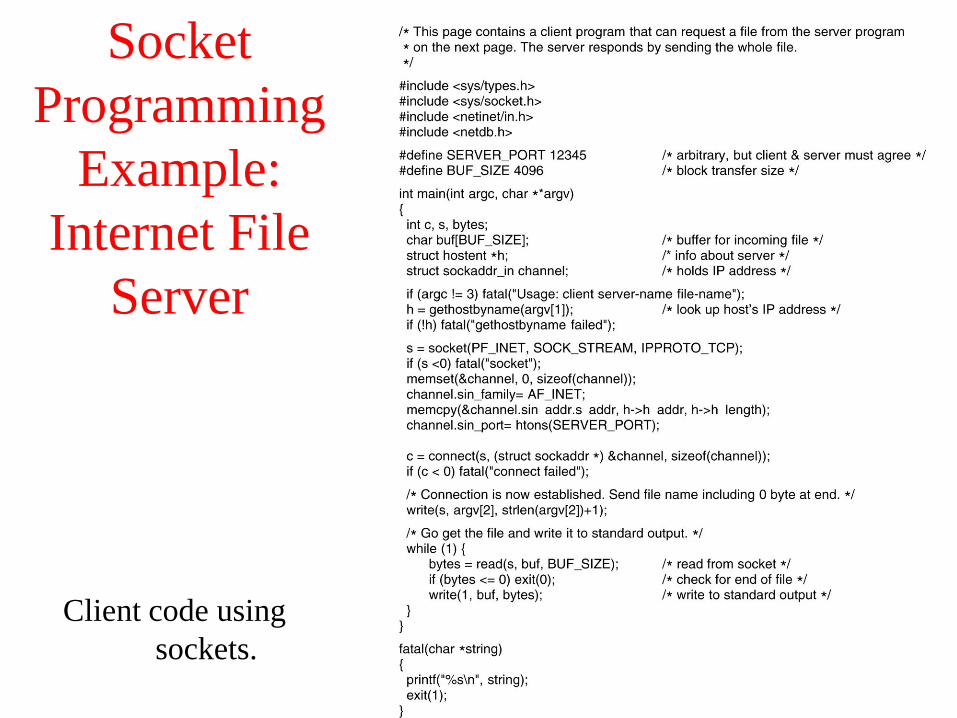
Socket
Programming
Example:
Internet File
Server
Client code using
sockets.
6-6-1

Socket
Programming
Example:
Internet File
Server (2)
Client code using
sockets.
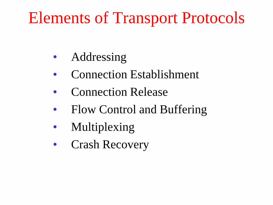
Elements of Transport Protocols
• Addressing
• Connection Establishment
• Connection Release
• Flow Control and Buffering
• Multiplexing
• Crash Recovery

Transport Protocol
(a) Environment of the data link layer.
(b) Environment of the transport layer.

Addressing
TSAPs, NSAPs and transport connections.
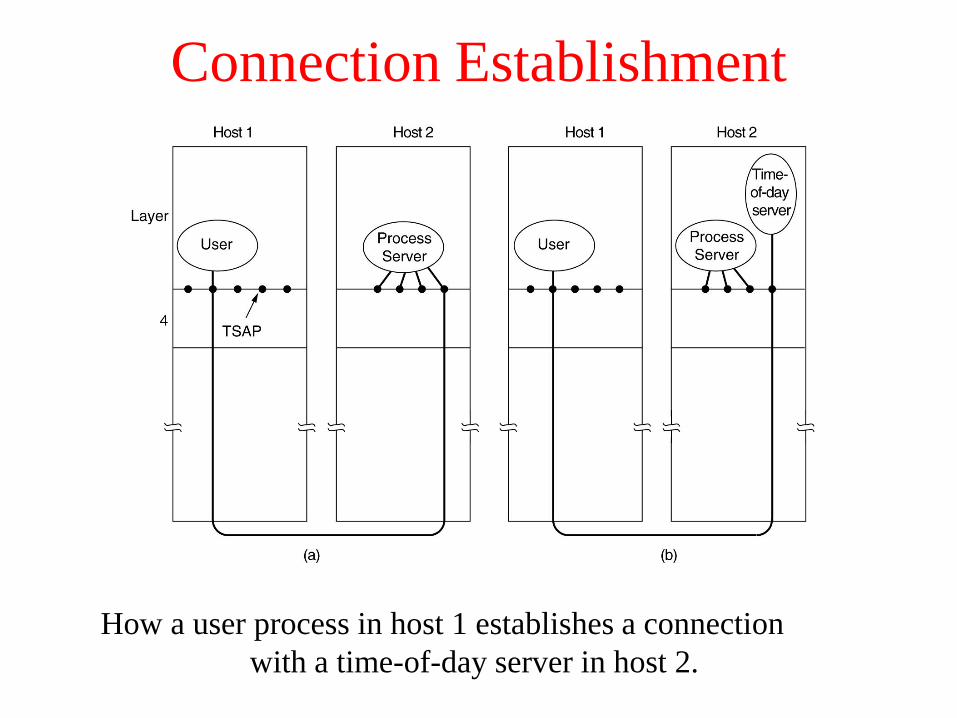
Connection Establishment
How a user process in host 1 establishes a connection
with a time-of-day server in host 2.

Connection Establishment (2)
(a) TPDUs may not enter the forbidden region.
(b) The resynchronization problem.

Connection Establishment (3)
Three protocol scenarios for establishing a connection using a
three-way handshake. CR denotes CONNECTION REQUEST.
(a) Normal operation,
(b) Old CONNECTION REQUEST appearing out of nowhere.
(c) Duplicate CONNECTION REQUEST and duplicate ACK.

Connection Release
Abrupt disconnection with loss of data.

Connection Release (2)
The two-army problem.

Connection Release (3)
Four protocol scenarios for releasing a connection. (a) Normal case of a
three-way handshake. (b) final ACK lost.
6-14, a, b

Connection Release (4)
(c) Response lost. (d) Response lost and subsequent DRs lost.
6-14, c,d

Flow Control and Buffering
(a) Chained fixed-size buffers. (b) Chained variable-sized buffers.
(c) One large circular buffer per connection.
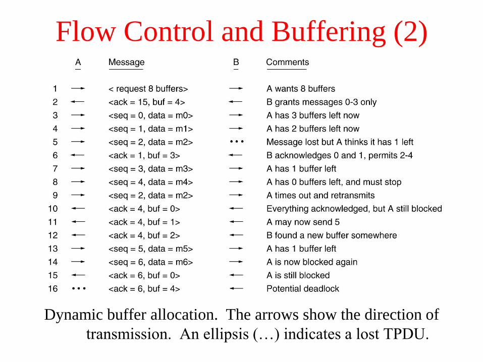
Flow Control and Buffering (2)
Dynamic buffer allocation. The arrows show the direction of
transmission. An ellipsis (…) indicates a lost TPDU.

Multiplexing
(a) Upward multiplexing. (b) Downward multiplexing.

Crash Recovery
Different combinations of client and server strategy.

A Simple Transport Protocol
• The Example Service Primitives
• The Example Transport Entity
• The Example as a Finite State Machine

The Example Transport Entity
The network layer packets used in our example.
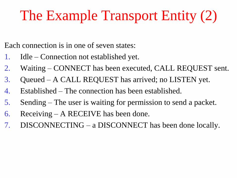
The Example Transport Entity (2)
Each connection is in one of seven states:
1. Idle – Connection not established yet.
2. Waiting – CONNECT has been executed, CALL REQUEST sent.
3. Queued – A CALL REQUEST has arrived; no LISTEN yet.
4. Established – The connection has been established.
5. Sending – The user is waiting for permission to send a packet.
6. Receiving – A RECEIVE has been done.
7. DISCONNECTING – a DISCONNECT has been done locally.
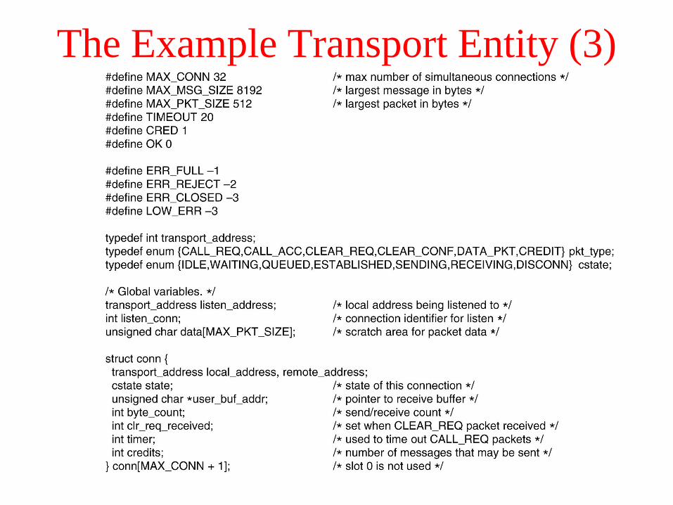
The Example Transport Entity (3)

The Example Transport Entity (4)
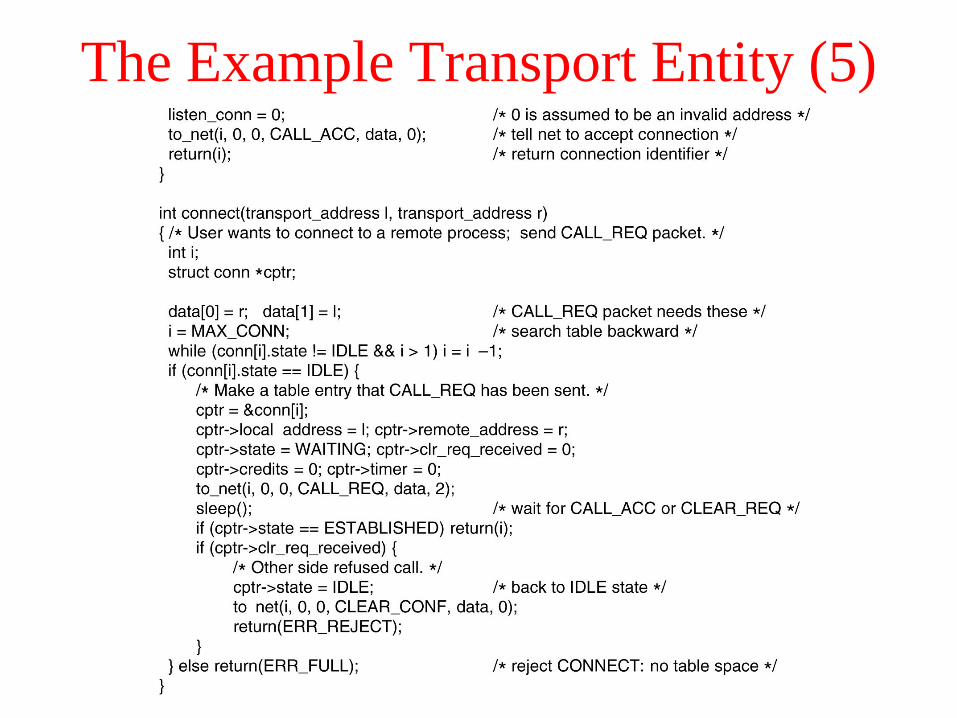
The Example Transport Entity (5)
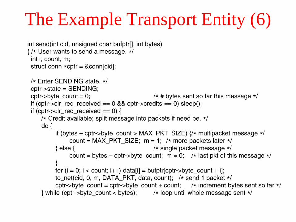
The Example Transport Entity (6)
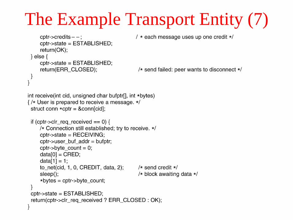
The Example Transport Entity (7)

The Example Transport Entity (8)
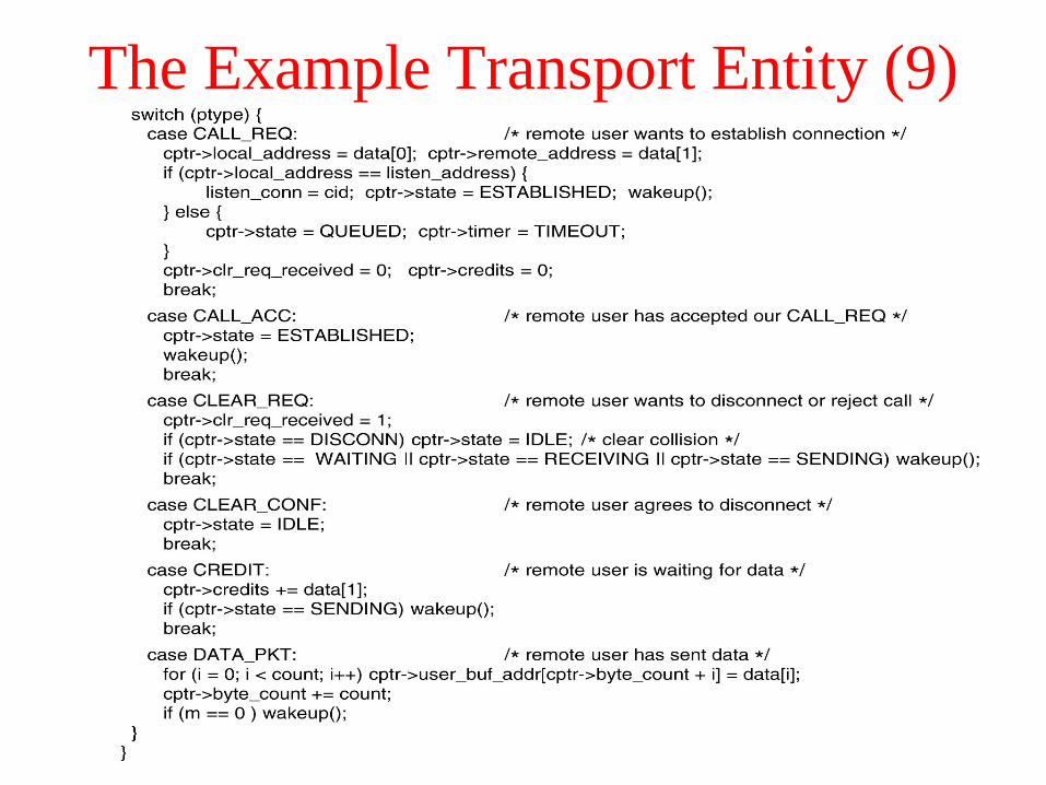
The Example Transport Entity (9)
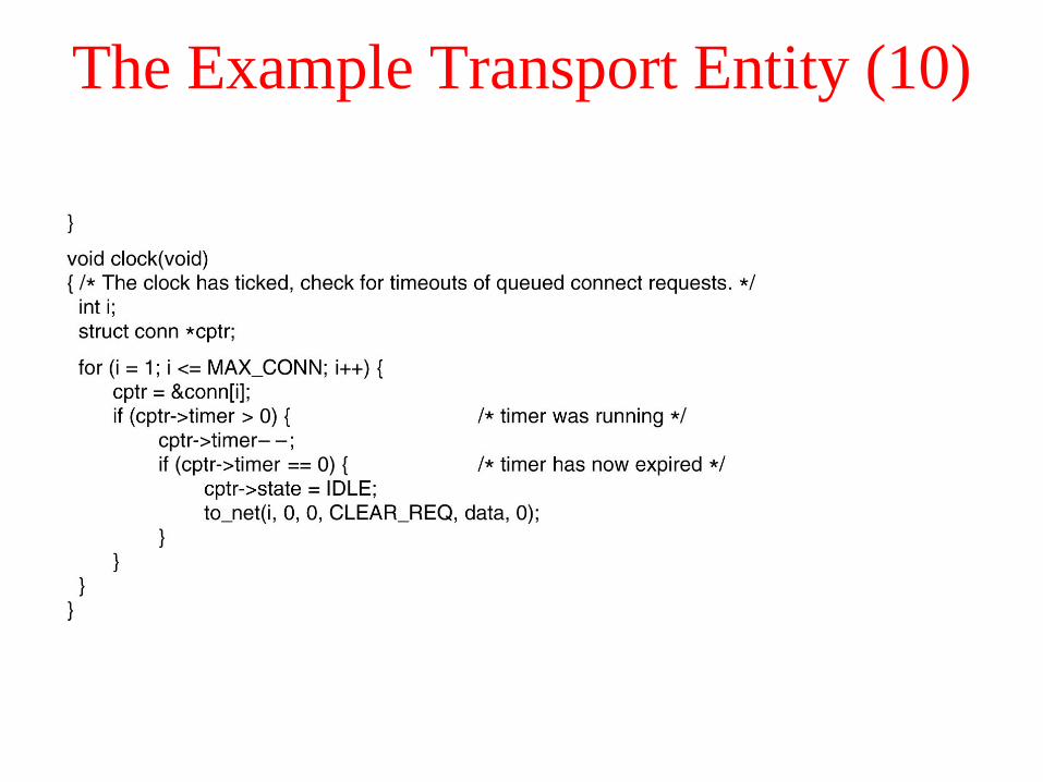
The Example Transport Entity (10)

The Example as a Finite State Machine
The example protocol as a
finite state machine. Each
entry has an optional
predicate, an optional action,
and the new state. The tilde
indicates that no major action
is taken. An overbar above a
predicate indicate the negation
of the predicate. Blank entries
correspond to impossible or
invalid events.

The Example as a Finite State Machine (2)
The example protocol in graphical form. Transitions that leave
the connection state unchanged have been omitted for simplicity.

The Internet Transport Protocols: UDP
• Introduction to UDP
• Remote Procedure Call
• The Real-Time Transport Protocol
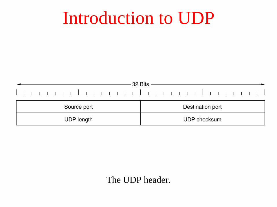
Introduction to UDP
The UDP header.
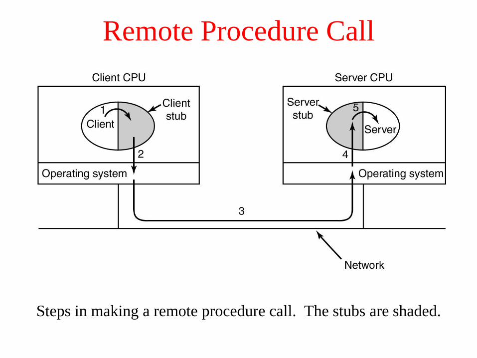
Remote Procedure Call
Steps in making a remote procedure call. The stubs are shaded.

The Real-Time Transport Protocol
(a) The position of RTP in the protocol stack. (b) Packet nesting.
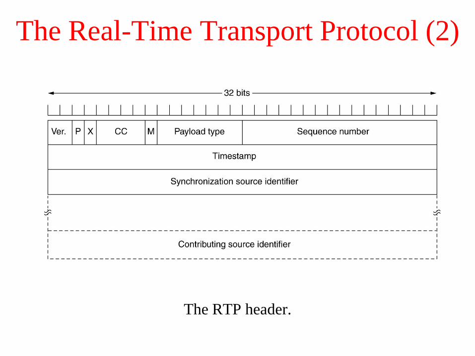
The Real-Time Transport Protocol (2)
The RTP header.
The Internet Transport Protocols: TCP
• Introduction to TCP
• The TCP Service Model
• The TCP Protocol
• The TCP Segment Header
• TCP Connection Establishment
• TCP Connection Release
• TCP Connection Management Modeling
• TCP Transmission Policy
• TCP Congestion Control
• TCP Timer Management
• Wireless TCP and UDP
• Transactional TCP
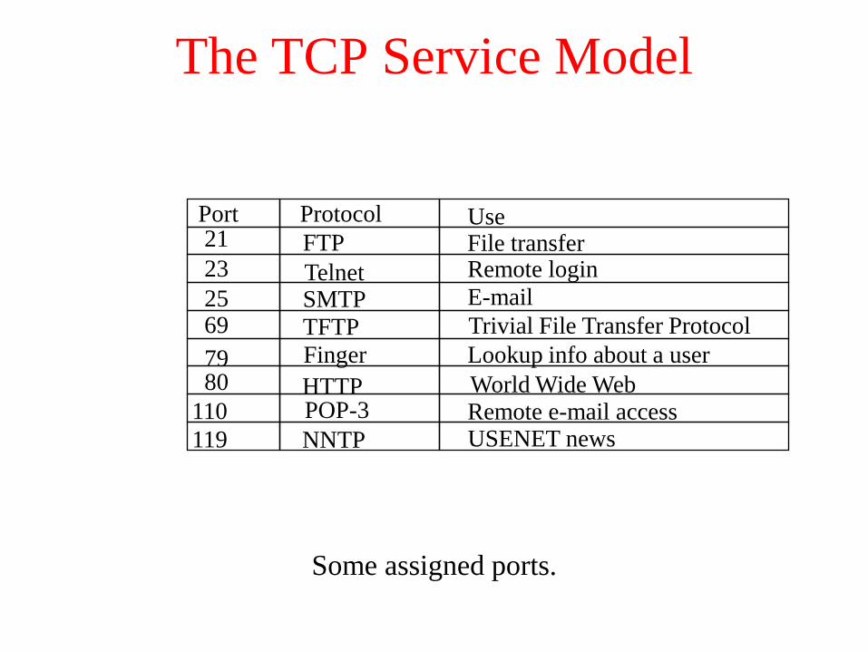
The TCP Service Model
Some assigned ports.
Port Protocol Use21 FTP File transfer23 Telnet Remote login
25 SMTP E-mail
69 TFTP Trivial File Transfer Protocol
79 Finger Lookup info about a user80 HTTP World Wide Web
110 POP-3 Remote e-mail access
119 NNTP USENET news

The TCP Service Model (2)
(a) Four 512-byte segments sent as separate IP datagrams.
(b) The 2048 bytes of data delivered to the application in a single
READ CALL.
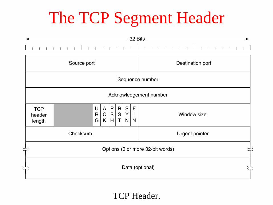
The TCP Segment Header
TCP Header.

The TCP Segment Header (2)
The pseudoheader included in the TCP checksum.
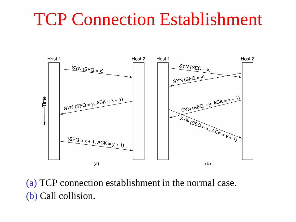
TCP Connection Establishment
(a) TCP connection establishment in the normal case.
(b) Call collision.
6-31
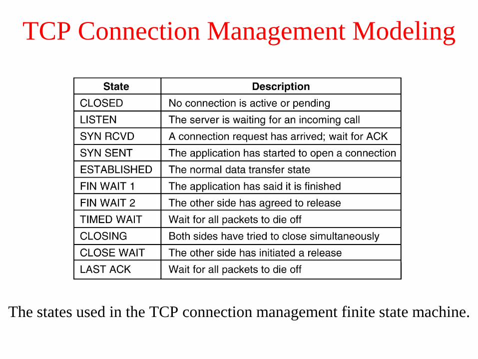
TCP Connection Management Modeling
The states used in the TCP connection management finite state machine.

TCP Connection Management Modeling (2)
TCP connection
management finite state
machine. The heavy solid
line is the normal path for a
client. The heavy dashed
line is the normal path for a
server. The light lines are
unusual events. Each
transition is labeled by the
event causing it and the
action resulting from it,
separated by a slash.

TCP Transmission Policy
Window management in TCP.
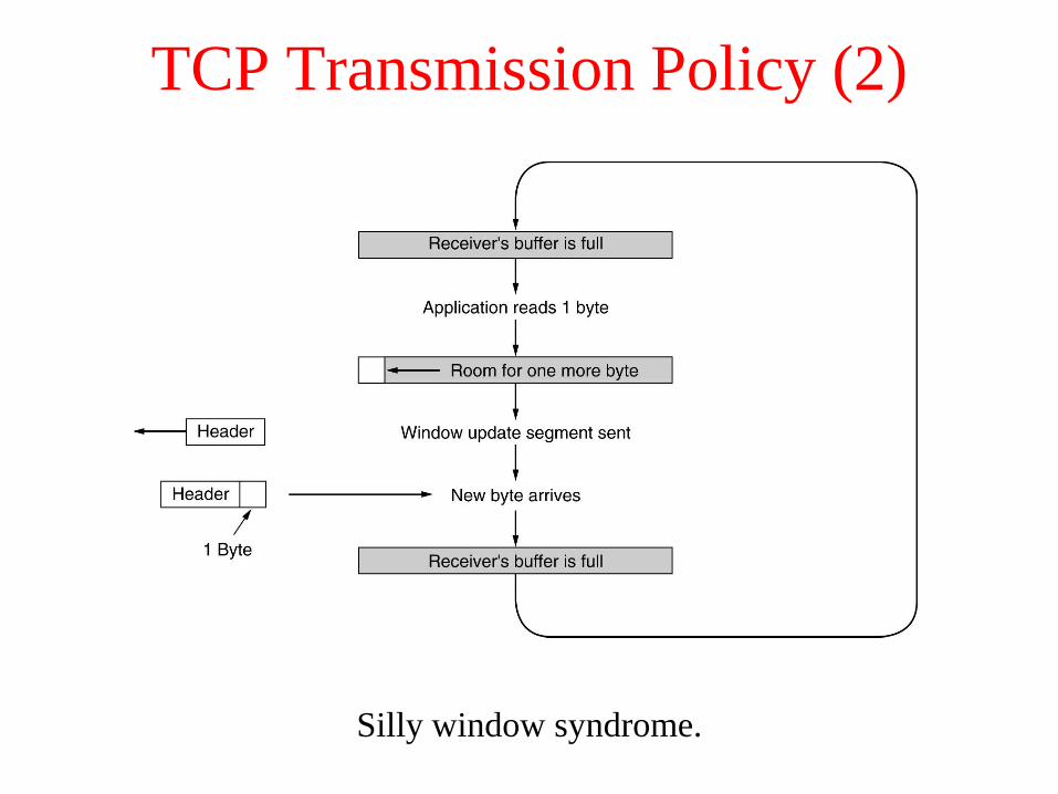
TCP Transmission Policy (2)
Silly window syndrome.

TCP Congestion Control
(a) A fast network feeding a low capacity receiver.
(b) A slow network feeding a high-capacity receiver.
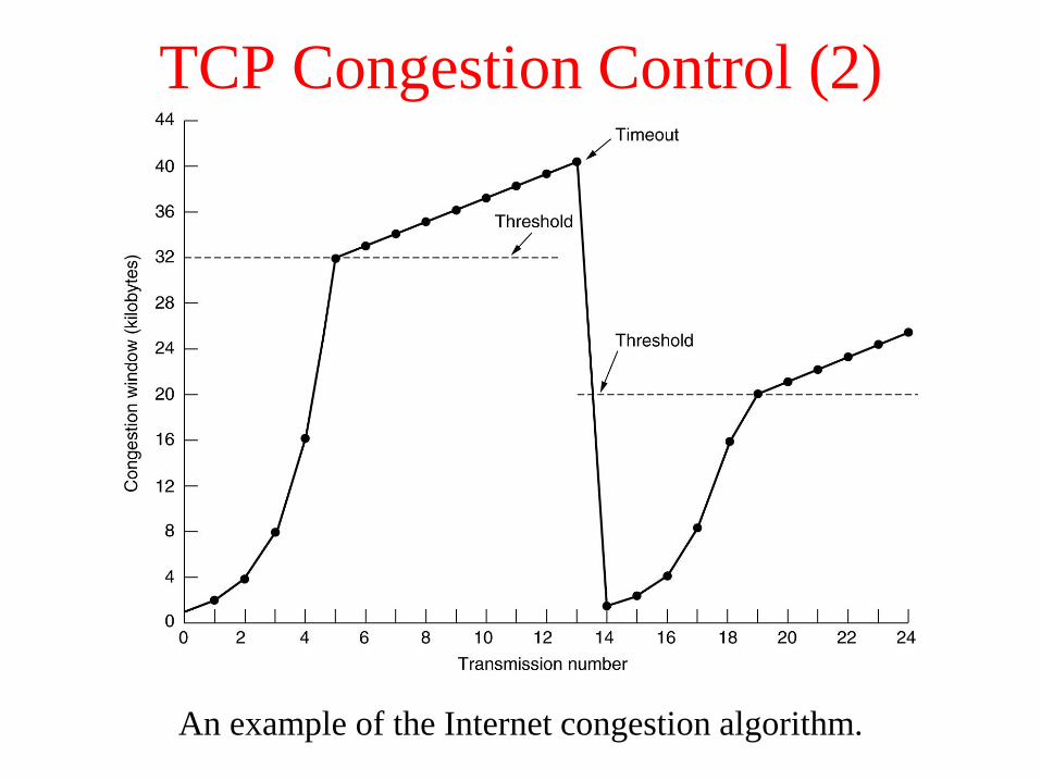
TCP Congestion Control (2)
An example of the Internet congestion algorithm.
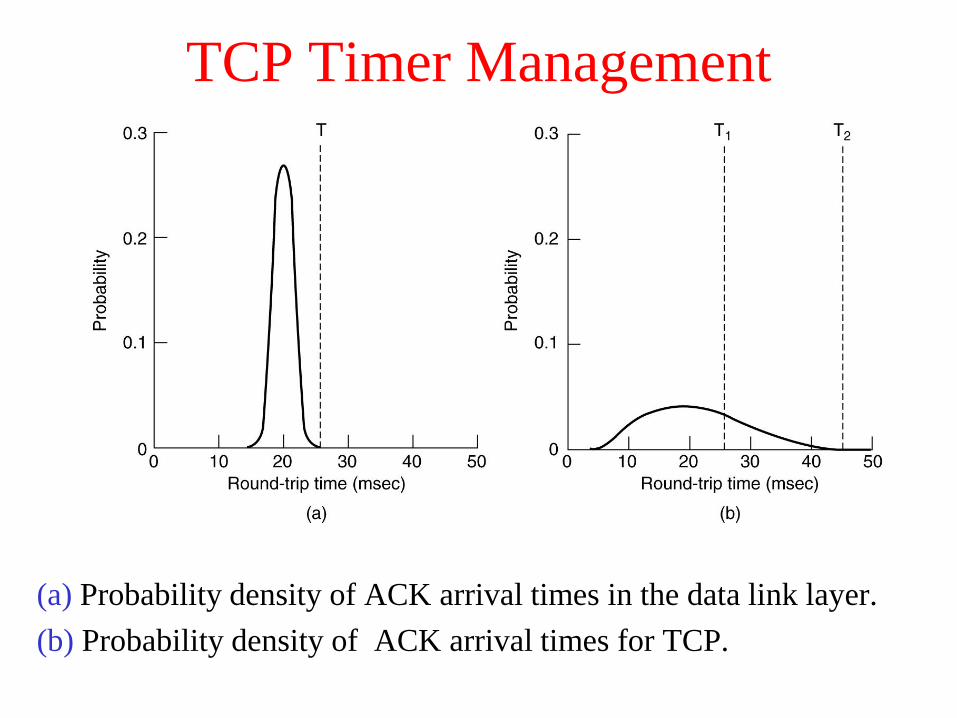
TCP Timer Management
(a) Probability density of ACK arrival times in the data link layer.
(b) Probability density of ACK arrival times for TCP.
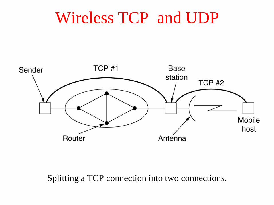
Wireless TCP and UDP
Splitting a TCP connection into two connections.
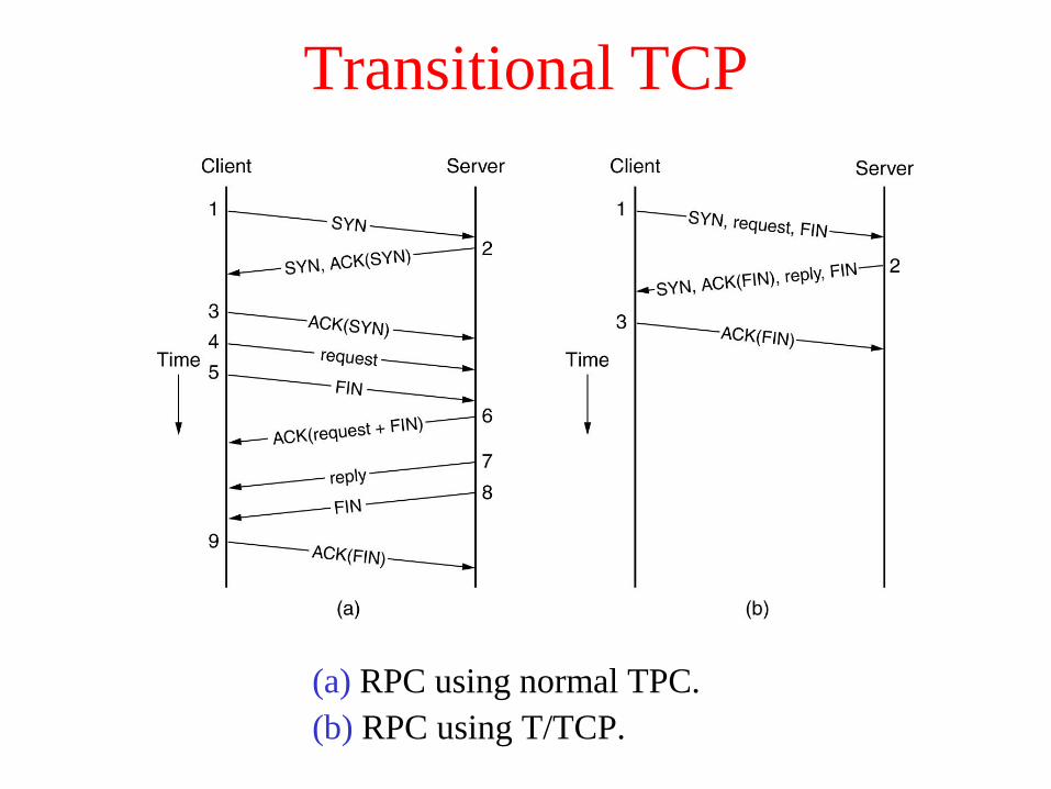
Transitional TCP
(a) RPC using normal TPC.
(b) RPC using T/TCP.

Performance Issues
• Performance Problems in Computer Networks
• Network Performance Measurement
• System Design for Better Performance
• Fast TPDU Processing
• Protocols for Gigabit Networks

Performance Problems in Computer Networks
The state of transmitting one megabit from San Diego to Boston
(a) At t = 0, (b) After 500 μsec, (c) After 20 msec, (d) after 40 msec.

Network Performance Measurement
The basic loop for improving network performance.
1. Measure relevant network parameters, performance.
2. Try to understand what is going on.
3. Change one parameter.

System Design for Better Performance
Rules:
1. CPU speed is more important than network speed.
2. Reduce packet count to reduce software overhead.
3. Minimize context switches.
4. Minimize copying.
5. You can buy more bandwidth but not lower delay.
6. Avoiding congestion is better than recovering from it.
7. Avoid timeouts.

System Design for Better Performance (2)
Response as a function of load.

System Design for Better Performance (3)
Four context switches to handle one packet
with a user-space network manager.

Fast TPDU Processing
The fast path from sender to receiver is shown with a heavy line.
The processing steps on this path are shaded.
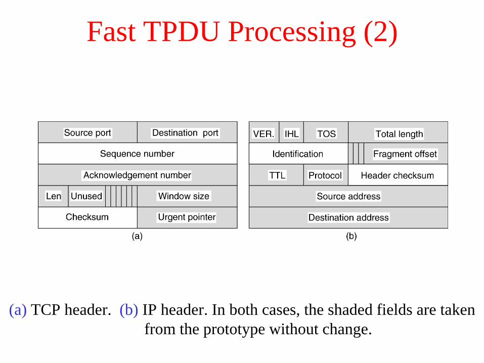
Fast TPDU Processing (2)
(a) TCP header. (b) IP header. In both cases, the shaded fields are taken
from the prototype without change.

Fast TPDU Processing (3)
A timing wheel.
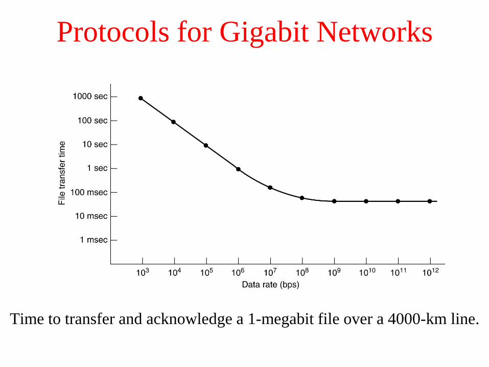
Protocols for Gigabit Networks
Time to transfer and acknowledge a 1-megabit file over a 4000-km line.
Related Documents