The Textile Interface Swatchbook: Creating Graphical User Interface-like Widgets with Conductive Embroidery Scott Gilliland, Nicholas Komor, Thad Starner, and Clint Zeagler GVU Center, Georgia Institute of Technology {scott.gilliland,thad}@cc.gatech.edu, [email protected], [email protected] Abstract The Textile Interface Swatchbook demonstrates how con- ductive embroidery can render graphical user interface-like (GUI) widgets on fabric. Such widgets might be used to control mobile electronics such as a music player, mobile phone, or projected display. At present, six swatches have been created for the swatchbook: pleat, menu, rocker, multi- touch gesture, zipper, and proximity. The three most diverse and original are discussed here. In addition, we develop a hybrid resistive-capacitive touch sensing technique de- signed to be more tolerant to the flexing typical of fabric. We hope to develop the Textile Interface Swatchbook into a reference tool for textile interfaces. 1 Introduction and Related Work In 1997, Rehmi Post and Maggie Orth introduced the wearable computing community to interfaces that could be embroidered using conductive thread [6]. Touches to the embroidery could be sensed using low cost capacitive cir- cuits, and soon Post, Orth, and their colleagues would de- sign keyboards, jogwheels, and other elements [7]. How- ever, the use of such textile widgets remained limited to professionals and hobbyists with specific skills and hands- on knowledge in circuitry and sewing. Researchers con- tinue to advance textile electronics along various dimen- sions [3, 4, 5], and electronic textile toolkits have been de- veloped for interesting middle and high school students in electronics [1]. However, little has been done to extend Post and Orth’s pioneering work in embroidered interfaces. We suggest that a systematic exploration of embroidered textile interfaces should be performed based on the common widgets available in GUI Toolkits. GUI widgets (buttons, sliders, menus, etc.) are familiar to most users and are often adapted for use on mobile phones and devices. Thus, textile interface widgets that adopt similar forms and metaphors should benefit from “walk-up” familiarity with users. Figure 1. A swatch being inserted into the Textile Interface Swatchbook’s interface spine. The spine connects the swatch to a laptop through USB. As each swatch is in- serted, the system automatically switches to the appropriate GUI (inset). However, textile interface widgets have physical bene- fits, and limitations, that GUI widgets do not. For exam- ple, raised embroidery can be used to guide the user’s hand naturally into position to use the interface without sight [2], whereas creating a tactile guide for GUI widgets is often im- practical. On the other hand, GUI widgets are not concerned with potential shorting when they are folded or crumpled. Thus, we do not wish to limit the design of textile interfaces to just those in GUIs. We propose the Textile Interface Swatchbook (TIS) as a means of demonstrating interface widget concepts and dis- tributing practical knowledge on the manufacture of textile widgets. The Textile Interface Swatchbook consists of three binders: one with an embedded microcontroller in its spine for interfacing swatches to a laptop’s GUI (Figure 1), a sec-

Welcome message from author
This document is posted to help you gain knowledge. Please leave a comment to let me know what you think about it! Share it to your friends and learn new things together.
Transcript
The Textile Interface Swatchbook: Creating Graphical User Interface-likeWidgets with Conductive Embroidery
Scott Gilliland, Nicholas Komor, Thad Starner, and Clint ZeaglerGVU Center, Georgia Institute of Technology
{scott.gilliland,thad}@cc.gatech.edu, [email protected], [email protected]
Abstract
The Textile Interface Swatchbook demonstrates how con-ductive embroidery can render graphical user interface-like(GUI) widgets on fabric. Such widgets might be used tocontrol mobile electronics such as a music player, mobilephone, or projected display. At present, six swatches havebeen created for the swatchbook: pleat, menu, rocker, multi-touch gesture, zipper, and proximity. The three most diverseand original are discussed here. In addition, we developa hybrid resistive-capacitive touch sensing technique de-signed to be more tolerant to the flexing typical of fabric.We hope to develop the Textile Interface Swatchbook into areference tool for textile interfaces.
1 Introduction and Related Work
In 1997, Rehmi Post and Maggie Orth introduced thewearable computing community to interfaces that could beembroidered using conductive thread [6]. Touches to theembroidery could be sensed using low cost capacitive cir-cuits, and soon Post, Orth, and their colleagues would de-sign keyboards, jogwheels, and other elements [7]. How-ever, the use of such textile widgets remained limited toprofessionals and hobbyists with specific skills and hands-on knowledge in circuitry and sewing. Researchers con-tinue to advance textile electronics along various dimen-sions [3, 4, 5], and electronic textile toolkits have been de-veloped for interesting middle and high school students inelectronics [1]. However, little has been done to extend Postand Orth’s pioneering work in embroidered interfaces.
We suggest that a systematic exploration of embroideredtextile interfaces should be performed based on the commonwidgets available in GUI Toolkits. GUI widgets (buttons,sliders, menus, etc.) are familiar to most users and are oftenadapted for use on mobile phones and devices. Thus, textileinterface widgets that adopt similar forms and metaphorsshould benefit from “walk-up” familiarity with users.
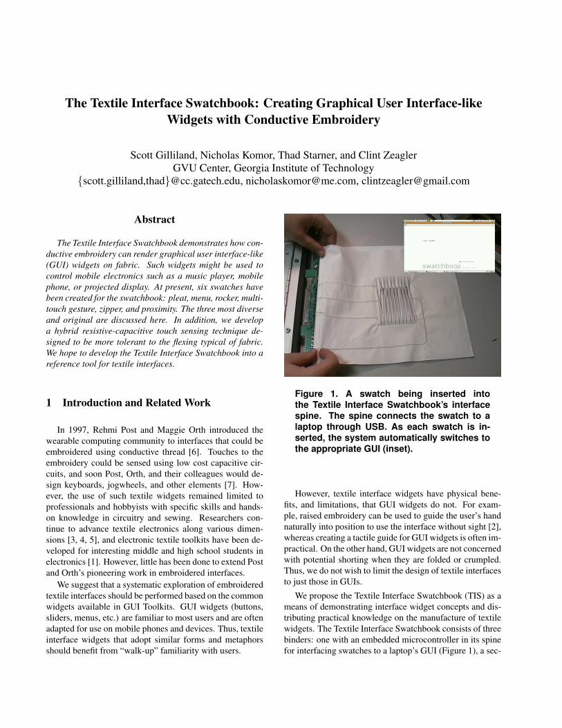
Figure 1. A swatch being inserted intothe Textile Interface Swatchbook’s interfacespine. The spine connects the swatch to alaptop through USB. As each swatch is in-serted, the system automatically switches tothe appropriate GUI (inset).
However, textile interface widgets have physical bene-fits, and limitations, that GUI widgets do not. For exam-ple, raised embroidery can be used to guide the user’s handnaturally into position to use the interface without sight [2],whereas creating a tactile guide for GUI widgets is often im-practical. On the other hand, GUI widgets are not concernedwith potential shorting when they are folded or crumpled.Thus, we do not wish to limit the design of textile interfacesto just those in GUIs.
We propose the Textile Interface Swatchbook (TIS) as ameans of demonstrating interface widget concepts and dis-tributing practical knowledge on the manufacture of textilewidgets. The Textile Interface Swatchbook consists of threebinders: one with an embedded microcontroller in its spinefor interfacing swatches to a laptop’s GUI (Figure 1), a sec-
ond that stores the functional textile widgets, and a third,currently being produced, containing electronics, manufac-turing, and fashion tips for each swatch. The Textile In-terface Swatchbook employs a familiar form factor to de-signers — the swatch. Designers often use swatches to helpvisualize the look of a color in a design. With the TextileInterface Swatchbook, designers insert a swatch into the in-terface spine to use the interface and gain experience withits affordances. Once satisfied, the designer pins the swatchto a garmet to determine if the interaction is appropriate atthat particular place on the body. We have noted that one ofthe best benefits of textile interfaces is the low time requiredto access them. Access time is a major factor in whether ornot a mobile interface is used [8], and by allowing design-ers to place textile interfaces on the body easily, the TISempowers designers to optimize for accessibility.
The TIS may also embolden computer scientists andelectrical engineers to attempt their own variants of textilewidgets. While engineers are often comfortable with theelectronics involved in textile widgets, the hands-on, prac-tical knowledge of producing electronic embroidery is of-ten a barrier. The TIS overcomes this barrier by providingworking prototypes of each widget.
In the following sections we describe the electronicsof the TIS, three sensing methods including an improvedresistive-capacitive hybrid touch-sensing circuit that is lesssensitive to the cloth changing shape than the typical ca-pacitive sensing circuit, and general principles of construct-ing embroidered textile interfaces. Next we discuss threenovel swatches in detail. We conclude with a discussionof swatches currently being prototyped and future improve-ments to the TIS itself.
2 Interface electronics
The TIS hardware consists of two circuit board designs:a swatch board which is sewn to the fabric swatches, and aspine board which is built into the spine of the swatchbook(see Figure 1). The swatch boards each plug in to the spineboard. This modular design allows for all of the logic tolie on the spine board, which needed to be built only once,while all of the fabric interfacing can be tested on a replace-able swatch board.
The spine board houses an Atmel Atmega168 microcon-troller, and an FTDI USB-RS232 allows the Atmel’s RS-232 interface to function as a USB serial interface. It alsocontains a 64-pin right-angle card-edge connector, allow-ing our swatch boards to plug directly into the spine boardwithout any additional parts on that board.
We built the system with three main methods of sens-ing in mind: analog sensing of resistance, capacitive touchsensing, and a hybrid resistive-capacitive touch sensing.
2.1 Analog sensing
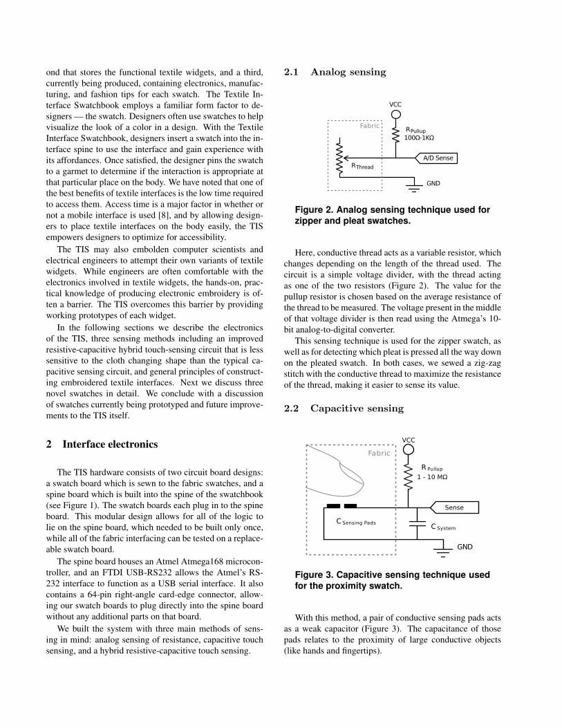
Figure 2. Analog sensing technique used forzipper and pleat swatches.
Here, conductive thread acts as a variable resistor, whichchanges depending on the length of the thread used. Thecircuit is a simple voltage divider, with the thread actingas one of the two resistors (Figure 2). The value for thepullup resistor is chosen based on the average resistance ofthe thread to be measured. The voltage present in the middleof that voltage divider is then read using the Atmega’s 10-bit analog-to-digital converter.
This sensing technique is used for the zipper swatch, aswell as for detecting which pleat is pressed all the way downon the pleated swatch. In both cases, we sewed a zig-zagstitch with the conductive thread to maximize the resistanceof the thread, making it easier to sense its value.
2.2 Capacitive sensing
Figure 3. Capacitive sensing technique usedfor the proximity swatch.
With this method, a pair of conductive sensing pads actsas a weak capacitor (Figure 3). The capacitance of thosepads relates to the proximity of large conductive objects(like hands and fingertips).
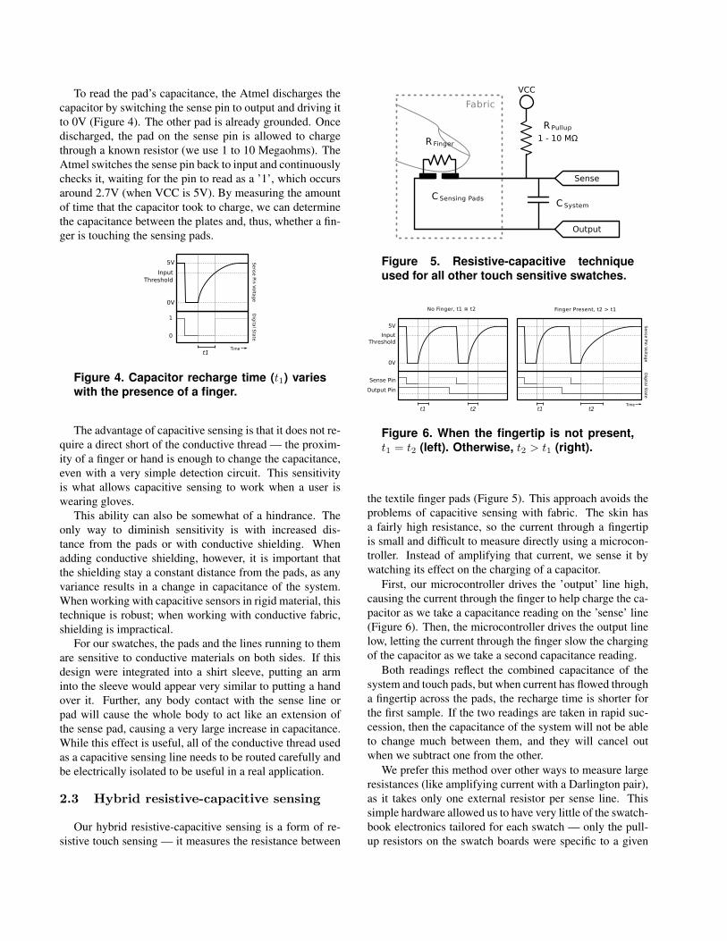
To read the pad’s capacitance, the Atmel discharges thecapacitor by switching the sense pin to output and driving itto 0V (Figure 4). The other pad is already grounded. Oncedischarged, the pad on the sense pin is allowed to chargethrough a known resistor (we use 1 to 10 Megaohms). TheAtmel switches the sense pin back to input and continuouslychecks it, waiting for the pin to read as a ’1’, which occursaround 2.7V (when VCC is 5V). By measuring the amountof time that the capacitor took to charge, we can determinethe capacitance between the plates and, thus, whether a fin-ger is touching the sensing pads.
Figure 4. Capacitor recharge time (t1) varieswith the presence of a finger.
The advantage of capacitive sensing is that it does not re-quire a direct short of the conductive thread — the proxim-ity of a finger or hand is enough to change the capacitance,even with a very simple detection circuit. This sensitivityis what allows capacitive sensing to work when a user iswearing gloves.
This ability can also be somewhat of a hindrance. Theonly way to diminish sensitivity is with increased dis-tance from the pads or with conductive shielding. Whenadding conductive shielding, however, it is important thatthe shielding stay a constant distance from the pads, as anyvariance results in a change in capacitance of the system.When working with capacitive sensors in rigid material, thistechnique is robust; when working with conductive fabric,shielding is impractical.
For our swatches, the pads and the lines running to themare sensitive to conductive materials on both sides. If thisdesign were integrated into a shirt sleeve, putting an arminto the sleeve would appear very similar to putting a handover it. Further, any body contact with the sense line orpad will cause the whole body to act like an extension ofthe sense pad, causing a very large increase in capacitance.While this effect is useful, all of the conductive thread usedas a capacitive sensing line needs to be routed carefully andbe electrically isolated to be useful in a real application.
2.3 Hybrid resistive-capacitive sensing
Our hybrid resistive-capacitive sensing is a form of re-sistive touch sensing — it measures the resistance between
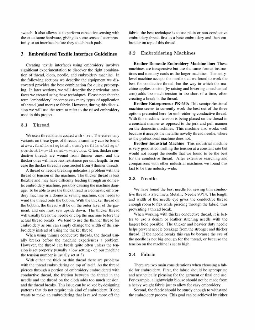
Figure 5. Resistive-capacitive techniqueused for all other touch sensitive swatches.
Figure 6. When the fingertip is not present,t1 = t2 (left). Otherwise, t2 > t1 (right).
the textile finger pads (Figure 5). This approach avoids theproblems of capacitive sensing with fabric. The skin hasa fairly high resistance, so the current through a fingertipis small and difficult to measure directly using a microcon-troller. Instead of amplifying that current, we sense it bywatching its effect on the charging of a capacitor.
First, our microcontroller drives the ’output’ line high,causing the current through the finger to help charge the ca-pacitor as we take a capacitance reading on the ’sense’ line(Figure 6). Then, the microcontroller drives the output linelow, letting the current through the finger slow the chargingof the capacitor as we take a second capacitance reading.
Both readings reflect the combined capacitance of thesystem and touch pads, but when current has flowed througha fingertip across the pads, the recharge time is shorter forthe first sample. If the two readings are taken in rapid suc-cession, then the capacitance of the system will not be ableto change much between them, and they will cancel outwhen we subtract one from the other.
We prefer this method over other ways to measure largeresistances (like amplifying current with a Darlington pair),as it takes only one external resistor per sense line. Thissimple hardware allowed us to have very little of the swatch-book electronics tailored for each swatch — only the pull-up resistors on the swatch boards were specific to a given
swatch. It also allows us to perform capacitive sensing withthe exact same hardware, giving us some sense of user prox-imity to an interface before they touch both pads.
3 Embroidered Textile Interface Guidelines
Creating textile interfaces using embroidery involvessignificant experimentation to discover the right combina-tion of thread, cloth, needle, and embroidery machine. Inthe following sections we describe the equipment we dis-covered provides the best combination for quick prototyp-ing. In later sections, we will describe the particular inter-faces we created using these techniques. Please note that theterm “embroidery” encompasses many types of applicationof thread (and more) to fabric. However, during this discus-sion we will use the term to refer to the raised embroideryused in this project.
3.1 Thread
We use a thread that is coated with silver. There are manyvariants on these types of threads; a summary can be foundat www.fashioningtech.com/profiles/blogs/conductive-thread-overview. Often, thicker con-ductive threads are wound from thinner ones, and thethicker ones will have less resistance per unit length. In ourcase the thicker thread is constructed from 4 thinner threads.
A thread or needle breaking indicates a problem with thethread or tension of the machine. The thicker thread is lessflexible and may have difficulty feeding through an domes-tic embroidery machine, possibly causing the machine dam-age. To be able to use the thick thread in a domestic embroi-dery machine or a domestic sewing machine, one needs towind the thread onto the bobbin. With the thicker thread onthe bobbin, the thread will be on the outer layer of the gar-ment, and one must sew upside down. The thicker threadwill usually break the needle or clog the machine before theactual thread breaks. We tend to use the thinner thread forembroidery as one can simply change the width of the em-broidery instead of using the thicker thread.
When using thinner conductive threads, the thread usu-ally breaks before the machine experiences a problem.However, the thread can break quite often unless the ten-sion is set properly (usually a low setting - on our machinethe tension number is usually set at 3).
With either the thick or thin thread there are problemswith the thread embroidering on top of itself. As the threadpierces through a portion of embroidery embroidered withconductive thread, the friction between the thread in theneedle and the thread on the cloth adds too much tension,and the thread breaks. This issue can be solved by designingpatterns that do not require this kind of embroidery. If onewants to make an embroidering that is raised more off the
fabric, the best technique is to use plain or non-conductiveembroidery thread first as a base embroidery and then em-broider on top of this thread.
3.2 Embroidering Machines
Brother Domestic Embroidery Machine line: Thesemachines are inexpensive but use the same format instruc-tions and memory cards as the larger machines. The entry-level machine accepts the needle that we found to work thebest for conductive thread, but the way in which the ma-chine applies tension (by raising and lowering a mechanicalarm) adds too much tension in too short of a time, oftencreating a break in the thread.
Brother Entrepreneur PR-650: This semiprofessionalmachine seems to currently work the best out of the threeoptions presented here for embroidering conductive thread.With this machine, tension is being placed on the thread ina constant manner as opposed to the jerk and pull manneron the domestic machines. This machine also works wellbecause it accepts the metallic novelty thread needle, whereas the professional machine does not.
Brother Industrial Machine This industrial machineis very good at controlling the tension at a constant rate butwould not accept the needle that we found to be the bestfor the conductive thread. After extensive searching andcomparisons with other industrial machines we found thisfact to be true industry-wide.
3.3 Needle
We have found the best needle for sewing thin conduc-tive thread is a Schmetz Metallic Needle 90/14. The lengthand width of the needle eye gives the conductive threadenough room to flex while piercing through the fabric, thuspreventing a thread break.
When working with thicker conductive thread, it is bet-ter to use a denim or leather stitching needle with thelargest hole possible. The thicker and heavier duty needlehelps prevent needle breakage from the stronger and thickerthread. If the needle breaks this can be because the eye ofthe needle is not big enough for the thread, or because thetension on the machine is set to high.
3.4 Fabric
There are two main considerations when choosing a fab-ric for embroidery. First, the fabric should be appropriateand aesthetically pleasing for the garment or final end use.For example, a lightweight blouse should not be made froma heavy weight fabric just to allow for easy embroidery.
Second, the fabric should be sturdy enough to withstandthe embroidery process. This goal can be achieved by either
picking a heavyweight fabric, or by picking a lightweightfabric with strong yarns or strong fiber content. Within thedesign of CAD-based embroidery, there are many optionsas to how to treat each aspect of the design: pull compen-sation, stitch density, stitch direction, etc. These settingsallow a designer to compensate for issues that the fabricmay present. The designer requires knowledge all the waydown to the construction of the textile. The designer mustask himself “will this fabric even allow this particular de-sign.” As an analogy, imagine drying oneself with tissuepaper rather than a towel made from terry cloth.
Lighter weight fabrics should be embroidered with a sta-bilizer backing. The lighter the fabric, the easier it gath-ers around a stitch, causing wrinkling. Stabilizer comes inmany different forms. For really light weight fabrics thatneed a stiffer stabilizer we choose to cut away the stabilizerafter the embroidery is complete. With a medium weightfabric one may be able to use a water soluble stabilizer.
The looser the fabric is when hooped, the more the fabriccan gather and wrinkle. When the fabric and stabilizer arehooped properly, the result should resemble a drum. Oneshould be able to flick a finger at the hooped fabric and heara thump.
When wrinkling occurs, it can also mean that the threadtension is set too high. The threads used on an embroiderymachine tend to be a little elastic, so that as the machineworks with a design, it can tug on the fabric causing it togather. There is no one answer on what tension is correctdue to the nature of each thread and fabric. Some wrinklingshould be expected. When using a cotton fabric, an ironset with high heat and steam can remove a majority of thiswrinkling.
When creating our Textile Interface Swatchbook, wescreen printed the back of the cotton fabric with plastisolscreen print ink to eliminate the fraying of the edges of thefabric. This process also insulates the conductive thread onthe back of the fabric.
4 Textile Interfaces
4.1 Rocker Switch
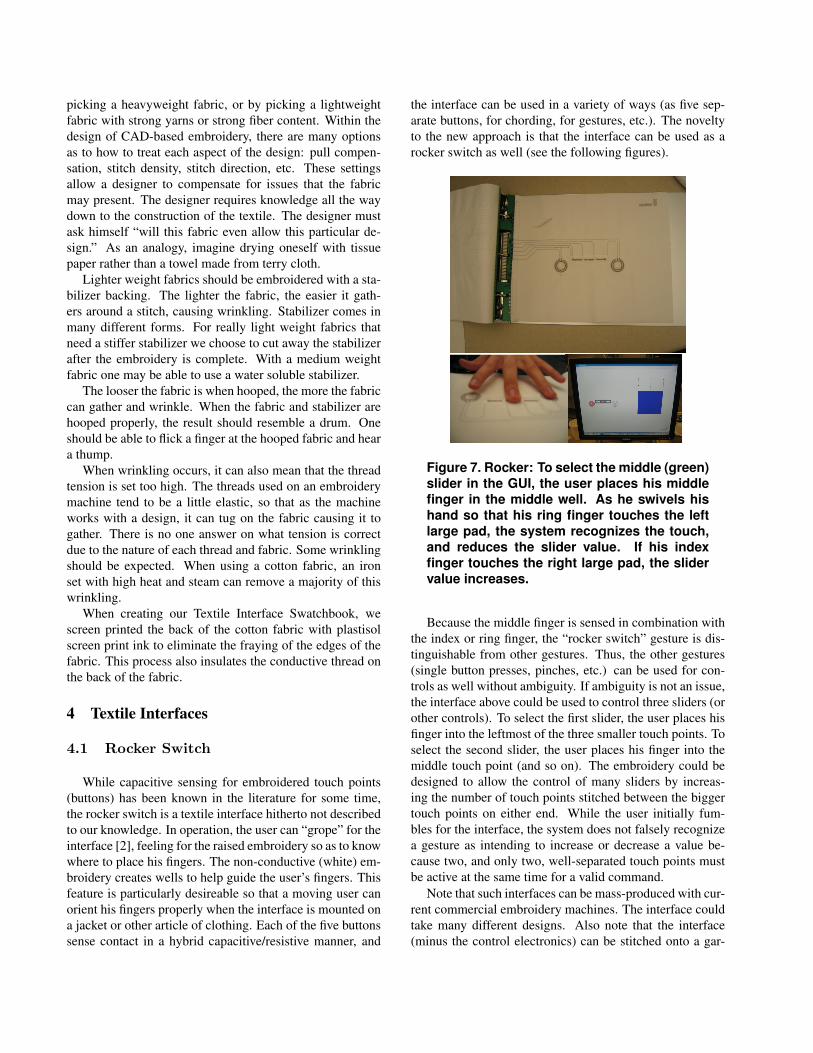
While capacitive sensing for embroidered touch points(buttons) has been known in the literature for some time,the rocker switch is a textile interface hitherto not describedto our knowledge. In operation, the user can “grope” for theinterface [2], feeling for the raised embroidery so as to knowwhere to place his fingers. The non-conductive (white) em-broidery creates wells to help guide the user’s fingers. Thisfeature is particularly desireable so that a moving user canorient his fingers properly when the interface is mounted ona jacket or other article of clothing. Each of the five buttonssense contact in a hybrid capacitive/resistive manner, and
the interface can be used in a variety of ways (as five sep-arate buttons, for chording, for gestures, etc.). The noveltyto the new approach is that the interface can be used as arocker switch as well (see the following figures).
Figure 7. Rocker: To select the middle (green)slider in the GUI, the user places his middlefinger in the middle well. As he swivels hishand so that his ring finger touches the leftlarge pad, the system recognizes the touch,and reduces the slider value. If his indexfinger touches the right large pad, the slidervalue increases.
Because the middle finger is sensed in combination withthe index or ring finger, the “rocker switch” gesture is dis-tinguishable from other gestures. Thus, the other gestures(single button presses, pinches, etc.) can be used for con-trols as well without ambiguity. If ambiguity is not an issue,the interface above could be used to control three sliders (orother controls). To select the first slider, the user places hisfinger into the leftmost of the three smaller touch points. Toselect the second slider, the user places his finger into themiddle touch point (and so on). The embroidery could bedesigned to allow the control of many sliders by increas-ing the number of touch points stitched between the biggertouch points on either end. While the user initially fum-bles for the interface, the system does not falsely recognizea gesture as intending to increase or decrease a value be-cause two, and only two, well-separated touch points mustbe active at the same time for a valid command.
Note that such interfaces can be mass-produced with cur-rent commercial embroidery machines. The interface couldtake many different designs. Also note that the interface(minus the control electronics) can be stitched onto a gar-
ment and washed, crumpled, or folded.
4.2 Menu
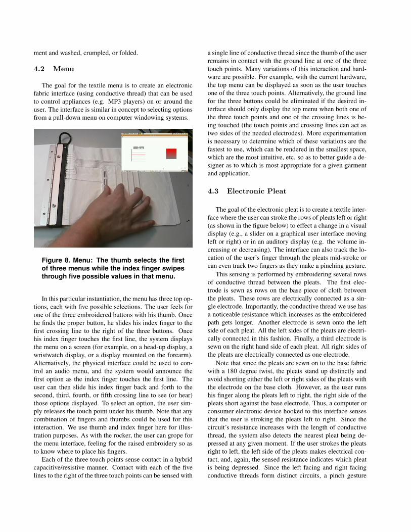
The goal for the textile menu is to create an electronicfabric interface (using conductive thread) that can be usedto control appliances (e.g. MP3 players) on or around theuser. The interface is similar in concept to selecting optionsfrom a pull-down menu on computer windowing systems.
Figure 8. Menu: The thumb selects the firstof three menus while the index finger swipesthrough five possible values in that menu.
In this particular instantiation, the menu has three top op-tions, each with five possible selections. The user feels forone of the three embroidered buttons with his thumb. Oncehe finds the proper button, he slides his index finger to thefirst crossing line to the right of the three buttons. Oncehis index finger touches the first line, the system displaysthe menu on a screen (for example, on a head-up display, awristwatch display, or a display mounted on the forearm).Alternatively, the physical interface could be used to con-trol an audio menu, and the system would announce thefirst option as the index finger touches the first line. Theuser can then slide his index finger back and forth to thesecond, third, fourth, or fifth crossing line to see (or hear)those options displayed. To select an option, the user sim-ply releases the touch point under his thumb. Note that anycombination of fingers and thumbs could be used for thisinteraction. We use thumb and index finger here for illus-tration purposes. As with the rocker, the user can grope forthe menu interface, feeling for the raised embroidery so asto know where to place his fingers.
Each of the three touch points sense contact in a hybridcapacitive/resistive manner. Contact with each of the fivelines to the right of the three touch points can be sensed with
a single line of conductive thread since the thumb of the userremains in contact with the ground line at one of the threetouch points. Many variations of this interaction and hard-ware are possible. For example, with the current hardware,the top menu can be displayed as soon as the user touchesone of the three touch points. Alternatively, the ground linefor the three buttons could be eliminated if the desired in-terface should only display the top menu when both one ofthe three touch points and one of the crossing lines is be-ing touched (the touch points and crossing lines can act astwo sides of the needed electrodes). More experimentationis necessary to determine which of these variations are thefastest to use, which can be rendered in the smallest space,which are the most intuitive, etc. so as to better guide a de-signer as to which is most appropriate for a given garmentand application.
4.3 Electronic Pleat
The goal of the electronic pleat is to create a textile inter-face where the user can stroke the rows of pleats left or right(as shown in the figure below) to effect a change in a visualdisplay (e.g., a slider on a graphical user interface movingleft or right) or in an auditory display (e.g. the volume in-creasing or decreasing). The interface can also track the lo-cation of the user’s finger through the pleats mid-stroke orcan even track two fingers as they make a pinching gesture.
This sensing is performed by embroidering several rowsof conductive thread between the pleats. The first elec-trode is sewn as rows on the base piece of cloth betweenthe pleats. These rows are electrically connected as a sin-gle electrode. Importantly, the conductive thread we use hasa noticeable resistance which increases as the embroideredpath gets longer. Another electrode is sewn onto the leftside of each pleat. All the left sides of the pleats are electri-cally connected in this fashion. Finally, a third electrode issewn on the right hand side of each pleat. All right sides ofthe pleats are electrically connected as one electrode.
Note that since the pleats are sewn on to the base fabricwith a 180 degree twist, the pleats stand up distinctly andavoid shorting either the left or right sides of the pleats withthe electrode on the base cloth. However, as the user runshis finger along the pleats left to right, the right side of thepleats short against the base electrode. Thus, a computer orconsumer electronic device hooked to this interface sensesthat the user is stroking the pleats left to right. Since thecircuit’s resistance increases with the length of conductivethread, the system also detects the nearest pleat being de-pressed at any given moment. If the user strokes the pleatsright to left, the left side of the pleats makes electrical con-tact, and, again, the sensed resistance indicates which pleatis being depressed. Since the left facing and right facingconductive threads form distinct circuits, a pinch gesture
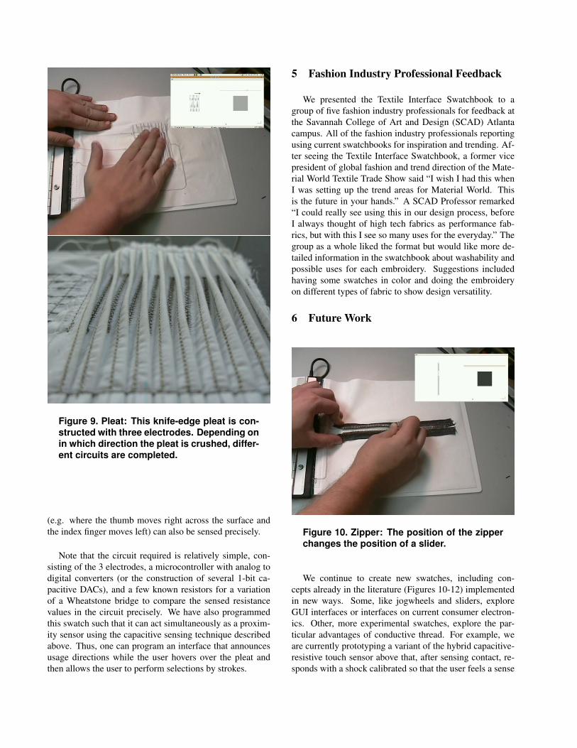
Figure 9. Pleat: This knife-edge pleat is con-structed with three electrodes. Depending onin which direction the pleat is crushed, differ-ent circuits are completed.
(e.g. where the thumb moves right across the surface andthe index finger moves left) can also be sensed precisely.
Note that the circuit required is relatively simple, con-sisting of the 3 electrodes, a microcontroller with analog todigital converters (or the construction of several 1-bit ca-pacitive DACs), and a few known resistors for a variationof a Wheatstone bridge to compare the sensed resistancevalues in the circuit precisely. We have also programmedthis swatch such that it can act simultaneously as a proxim-ity sensor using the capacitive sensing technique describedabove. Thus, one can program an interface that announcesusage directions while the user hovers over the pleat andthen allows the user to perform selections by strokes.
5 Fashion Industry Professional Feedback
We presented the Textile Interface Swatchbook to agroup of five fashion industry professionals for feedback atthe Savannah College of Art and Design (SCAD) Atlantacampus. All of the fashion industry professionals reportingusing current swatchbooks for inspiration and trending. Af-ter seeing the Textile Interface Swatchbook, a former vicepresident of global fashion and trend direction of the Mate-rial World Textile Trade Show said “I wish I had this whenI was setting up the trend areas for Material World. Thisis the future in your hands.” A SCAD Professor remarked“I could really see using this in our design process, beforeI always thought of high tech fabrics as performance fab-rics, but with this I see so many uses for the everyday.” Thegroup as a whole liked the format but would like more de-tailed information in the swatchbook about washability andpossible uses for each embroidery. Suggestions includedhaving some swatches in color and doing the embroideryon different types of fabric to show design versatility.
6 Future Work
Figure 10. Zipper: The position of the zipperchanges the position of a slider.
We continue to create new swatches, including con-cepts already in the literature (Figures 10-12) implementedin new ways. Some, like jogwheels and sliders, exploreGUI interfaces or interfaces on current consumer electron-ics. Other, more experimental swatches, explore the par-ticular advantages of conductive thread. For example, weare currently prototyping a variant of the hybrid capacitive-resistive touch sensor above that, after sensing contact, re-sponds with a shock calibrated so that the user feels a sense
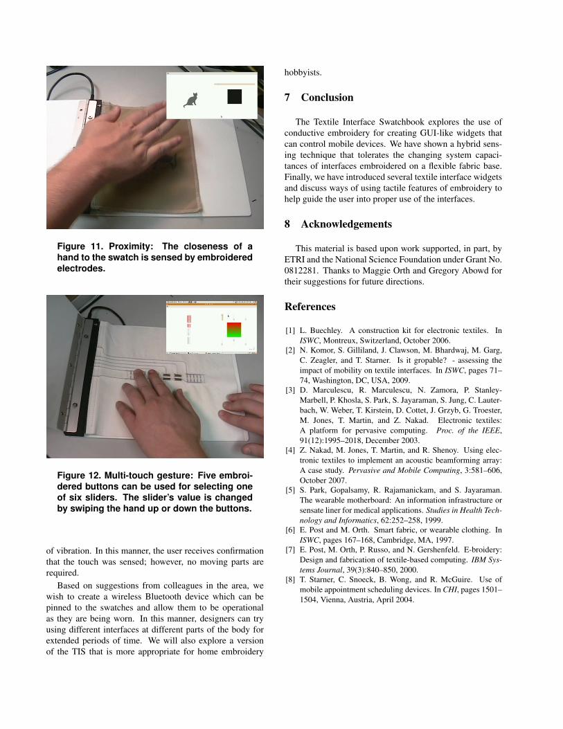
Figure 11. Proximity: The closeness of ahand to the swatch is sensed by embroideredelectrodes.
Figure 12. Multi-touch gesture: Five embroi-dered buttons can be used for selecting oneof six sliders. The slider’s value is changedby swiping the hand up or down the buttons.
of vibration. In this manner, the user receives confirmationthat the touch was sensed; however, no moving parts arerequired.
Based on suggestions from colleagues in the area, wewish to create a wireless Bluetooth device which can bepinned to the swatches and allow them to be operationalas they are being worn. In this manner, designers can tryusing different interfaces at different parts of the body forextended periods of time. We will also explore a versionof the TIS that is more appropriate for home embroidery
hobbyists.
7 Conclusion
The Textile Interface Swatchbook explores the use ofconductive embroidery for creating GUI-like widgets thatcan control mobile devices. We have shown a hybrid sens-ing technique that tolerates the changing system capaci-tances of interfaces embroidered on a flexible fabric base.Finally, we have introduced several textile interface widgetsand discuss ways of using tactile features of embroidery tohelp guide the user into proper use of the interfaces.
8 Acknowledgements
This material is based upon work supported, in part, byETRI and the National Science Foundation under Grant No.0812281. Thanks to Maggie Orth and Gregory Abowd fortheir suggestions for future directions.
References
[1] L. Buechley. A construction kit for electronic textiles. InISWC, Montreux, Switzerland, October 2006.
[2] N. Komor, S. Gilliland, J. Clawson, M. Bhardwaj, M. Garg,C. Zeagler, and T. Starner. Is it gropable? - assessing theimpact of mobility on textile interfaces. In ISWC, pages 71–74, Washington, DC, USA, 2009.
[3] D. Marculescu, R. Marculescu, N. Zamora, P. Stanley-Marbell, P. Khosla, S. Park, S. Jayaraman, S. Jung, C. Lauter-bach, W. Weber, T. Kirstein, D. Cottet, J. Grzyb, G. Troester,M. Jones, T. Martin, and Z. Nakad. Electronic textiles:A platform for pervasive computing. Proc. of the IEEE,91(12):1995–2018, December 2003.
[4] Z. Nakad, M. Jones, T. Martin, and R. Shenoy. Using elec-tronic textiles to implement an acoustic beamforming array:A case study. Pervasive and Mobile Computing, 3:581–606,October 2007.
[5] S. Park, Gopalsamy, R. Rajamanickam, and S. Jayaraman.The wearable motherboard: An information infrastructure orsensate liner for medical applications. Studies in Health Tech-nology and Informatics, 62:252–258, 1999.
[6] E. Post and M. Orth. Smart fabric, or wearable clothing. InISWC, pages 167–168, Cambridge, MA, 1997.
[7] E. Post, M. Orth, P. Russo, and N. Gershenfeld. E-broidery:Design and fabrication of textile-based computing. IBM Sys-tems Journal, 39(3):840–850, 2000.
[8] T. Starner, C. Snoeck, B. Wong, and R. McGuire. Use ofmobile appointment scheduling devices. In CHI, pages 1501–1504, Vienna, Austria, April 2004.
Related Documents


