THE TESTING APPROACH FOR FPGA LOGIC CELLS E. Bareiša, V. Jusas, K. Motiejūnas, R. Šeinauskas Kaunas University of Technology LITHUANIA EWDTW'04

THE TESTING APPROACH FOR FPGA LOGIC CELLS E. Bareiša, V. Jusas, K. Motiejūnas, R. Šeinauskas Kaunas University of Technology LITHUANIA EWDTW'04.
Jan 02, 2016
Welcome message from author
This document is posted to help you gain knowledge. Please leave a comment to let me know what you think about it! Share it to your friends and learn new things together.
Transcript
THE TESTING APPROACH FOR FPGA LOGIC CELLS
E. Bareiša, V. Jusas, K. Motiejūnas, R. Šeinauskas
Kaunas University of Technology
LITHUANIA
EWDTW'04

Topics
INTRODUCTION THE CIRCUIT TRANSFORMATION TEST PATTERN GENERATION THE EXPERIMENTS CONCLUSIONS
INTRODUCTION
For reprogrammable FPGAs two types of testing can be considered. One is the testing of unprogrammed FPGAs, which is accomplished by the producer right after manufacturing (Manufacturing-Oriented Test Procedure).
The other is the testing of the programmed FPGA, which is accomplished by the user when the device is deployed by a given application (Application-Oriented Test Procedure).

INTRODUCTION
The test vectors computed by a gate level test pattern generator with the gate level circuit netlist and stuck-at faults produce a low coverage for the FPGA implementation
FPGA implementation has a huge number of application configuration redundant faults.

INTRODUCTION
Elimination of redundant faults from the netlist of cells gives the reduction from 4% to 93%
On the other hand, the set of faults affecting the LUT bit cells requires of exhaustive testing of logic cells
INTRODUCTION
In this paper, we consider an approach of the exhaustive testing of logic cells for an FPGA configured circuit to implement a given application.
Such an approach lets to neglect the inner structure of the logic cell and test patterns generated according to our approach are able to detect all inner defects of logic cells that could be detected by a single test pattern

Exhaustive testing of logic cells
4 test
vectors
8 test
vectors
16 test
vectors
CLB CLB
CLB
Test generation approaches
The developing or using of special test generator
The use of conventional test generator with the circuit transformation
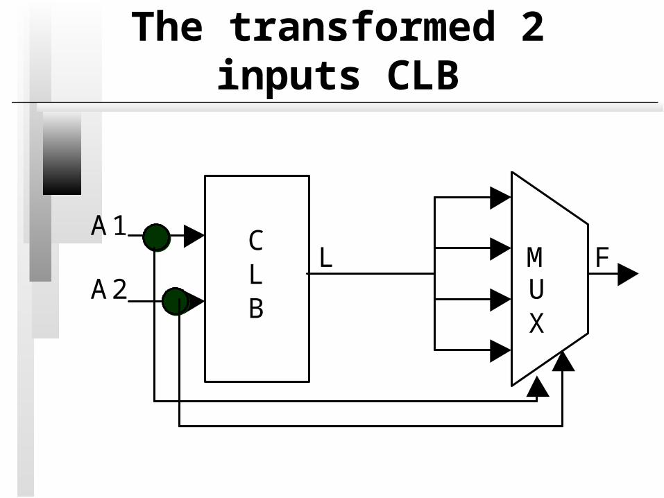
The transformed 2 inputs CLB
A1 L M F A2 U
X
CLB
The circuit transformation
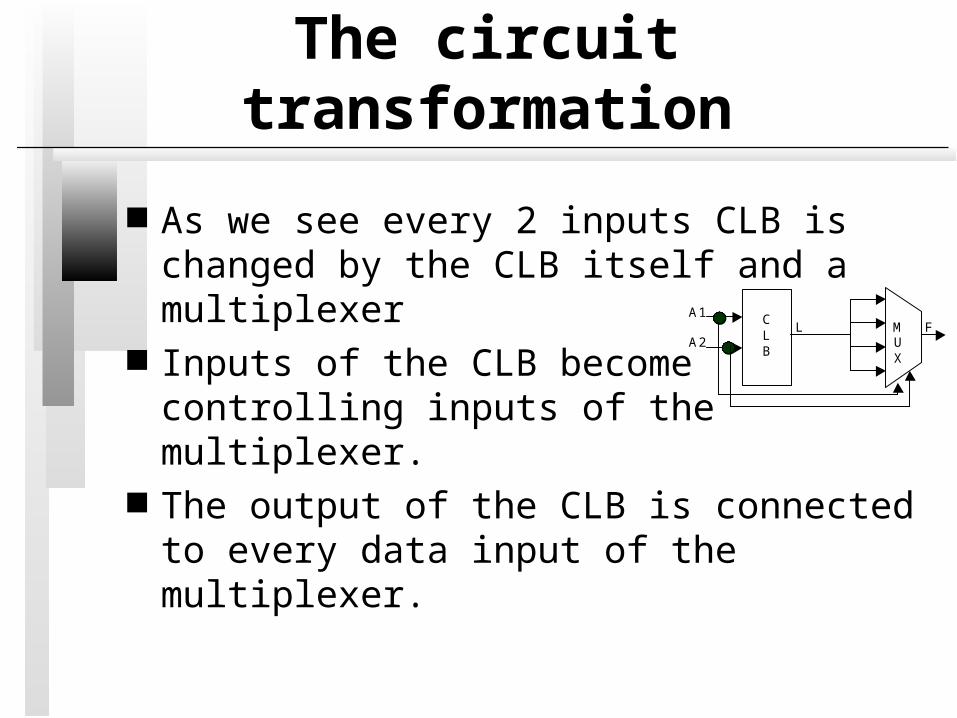
As we see every 2 inputs CLB is changed by the CLB itself and a multiplexer
Inputs of the CLB become controlling inputs of the multiplexer.
The output of the CLB is connected to every data input of the multiplexer.
A1 L M F A2 U
X
CLB

The list of stuck-at faults
Stuck-at faults are injected only on the data inputs of the multiplexer.
So we have 8 stuck-at faults on the inputs of the multiplexer.
A1 L M F A2 U
X
CLB
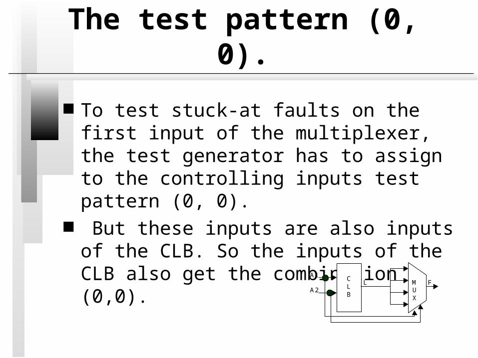
The test pattern (0, 0).
To test stuck-at faults on the first input of the multiplexer, the test generator has to assign to the controlling inputs test pattern (0, 0).
But these inputs are also inputs of the CLB. So the inputs of the CLB also get the combination (0,0). A1
L M F A2 U
X
CLB

The test pattern (0, 1).
To test stuck-at faults on the second input of the multiplexer, the test generator has to assign to the controlling inputs test pattern (0, 1).
A1 L M F A2 U
X
CLB

The exhaustive testing of CLB
In such a way, the test generator provides all 4 combinations to the inputs of the CLB
The presented transformation ensures the exhaustive testing of the 2 inputs CLB.
The same principle of the transformation is applicable to any number inputs of the CLB.

Multiplexer input faults
It is necessary to notice that at least half of multiplexer input faults in the proposed circuit transformation are redundant
Which multiplexer input fault is redundant depends on the function of the CLB
A test pattern generator has to spend a lot of time to conclude that the target fault is untestable
Multiplexer input faults
Usually, the conventional test generator is not efficient to find untestable faults
The functions of the CLB can be analyzed and redundant faults can be excluded from the multiplexer input fault list
Experiments
In the experiments, we used circuits from the ISCAS'85 benchmark suite.
The circuits were mapped into FPGA using the SynopsysTM synthesis tool and VirtexTM-II library.
The SynopsysTM test generation tool TetraMaxTM generated tests for the transformed circuit.

Circuits
The test generation was carried out for three circuits from the benchmark suite ISCAS'85: c432, c880 and c5315. The numbers of CLBs of all three circuits are presented in Table .
Circuit 2 inputsCLB
3 inputsCLB
4 inputsCLB
Total
C432 11 10 50 71C880 21 21 79 121C5315 109 62 319 490
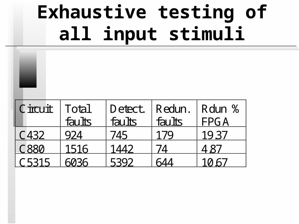
Exhaustive testing of all input stimuli
Circuit Totalfaults
Detect.faults
Redun.faults
Rdun %FPGA
C432 924 745 179 19.37C880 1516 1442 74 4.87C5315 6036 5392 644 10.67

Why the input stimuli of CLBs are not fully testable?
CLBs were made like primary outputs. That ensures the propagation of all input IP faults to the primary outputs. Such an experiment allows distinguishing between the problems of controlling the values on the inputs of the CLBs and propagating these values to the primary outputs.
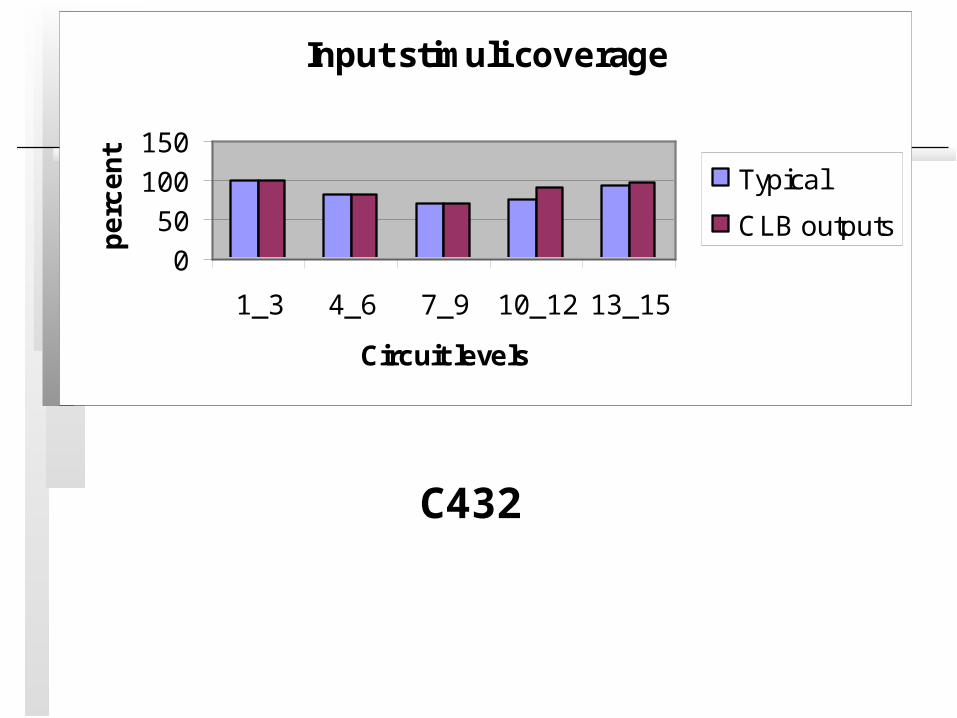
Input stimuli coverage
0
50
100
150
1_3 4_6 7_9 10_12 13_15
Circuit levels
pe
rce
nt
Typical
CLB outputs
C432
Untestable input stimuli of CLB
15.70% of CLB input stimuli were untestable because there was no capability to set an appropriate stimuli on the inputs of the CLB, 3.73% (84.30% - 80.63%) of CLB input stimuli were untestable because their effects were not propagated to the outputs of the circuit.
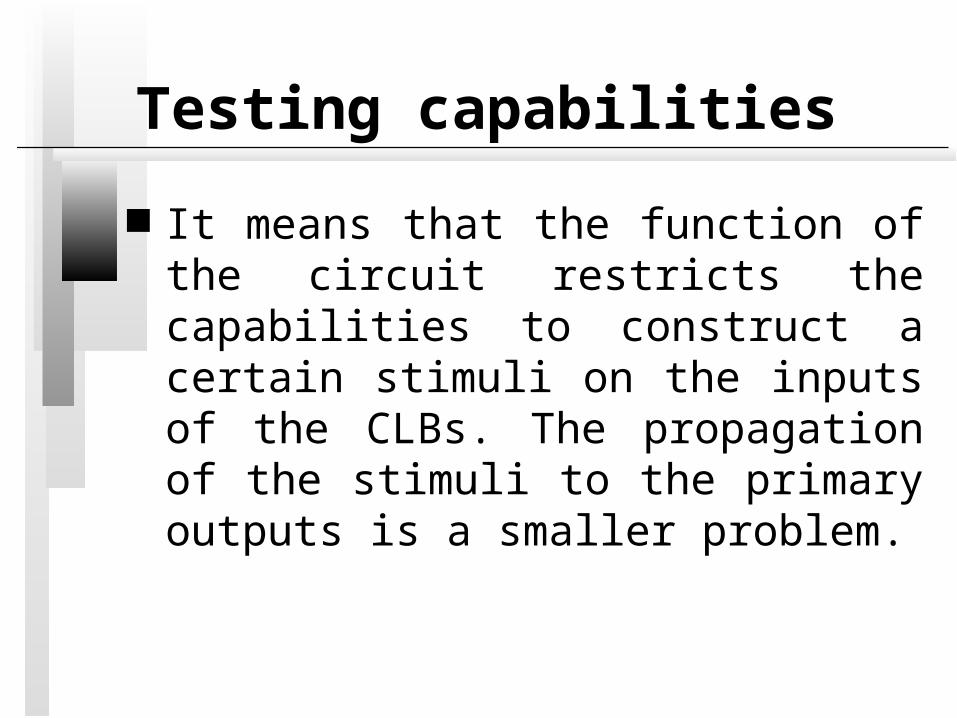
Testing capabilities
It means that the function of the circuit restricts the capabilities to construct a certain stimuli on the inputs of the CLBs. The propagation of the stimuli to the primary outputs is a smaller problem.
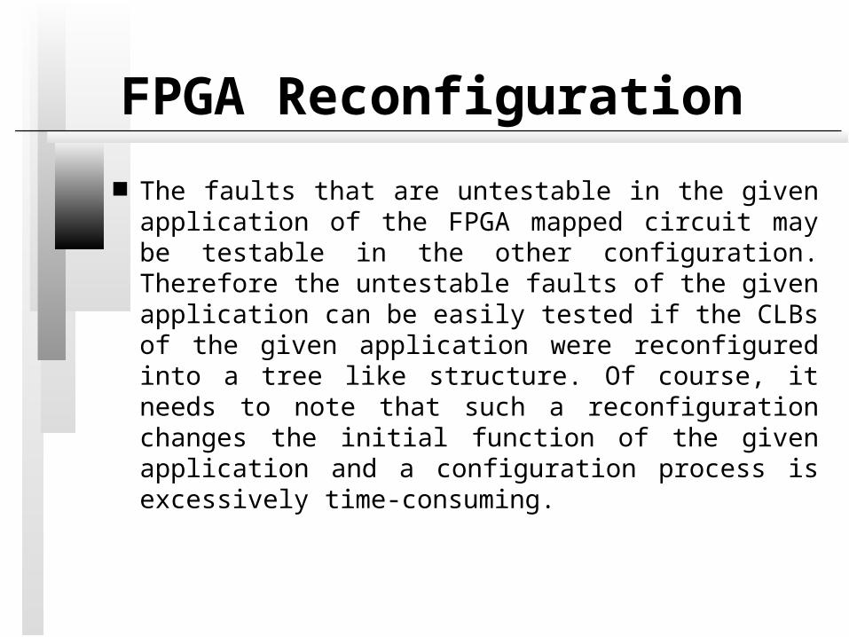
FPGA Reconfiguration
The faults that are untestable in the given application of the FPGA mapped circuit may be testable in the other configuration. Therefore the untestable faults of the given application can be easily tested if the CLBs of the given application were reconfigured into a tree like structure. Of course, it needs to note that such a reconfiguration changes the initial function of the given application and a configuration process is excessively time-consuming.
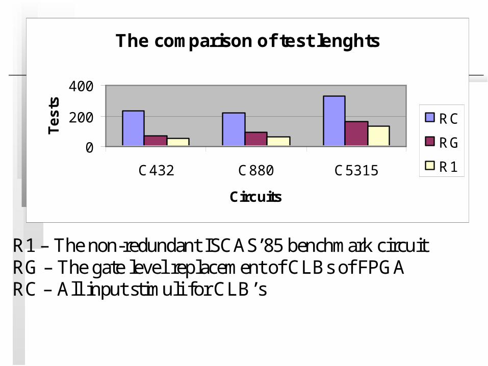
The comparison of test lenghts
0
200
400
C432 C880 C5315
Circuits
Te
sts
RC
RG
R1
R1 – The non-redundant ISCAS’85 benchmark circuitRG – The gate level replacement of CLBs of FPGARC – All input stimuli for CLB’s
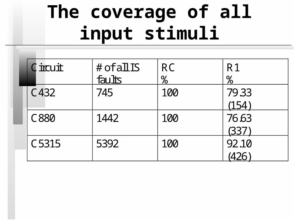
The coverage of all input stimuli
Circuit # of all ISfaults
RC%
R1%
C432 745 100 79.33(154)
C880 1442 100 76.63(337)
C5315 5392 100 92.10(426)
Conclusions
We considered a testing approach for an FPGA configured circuit to implement a given application. This approach is based on the exhaustive testing of every logic cell.
The exhaustive testing of logic cells ensures the detection of all defects in the inner structure of the logic cell. This does not depend on what configuration of the inner structure of the logic cell is used.
Conclusions
The exhaustive testing of logic cells detects all defects that could be detected by a single test pattern. But the length of the test is increased and a construction of such test requires some extra time to prove that certain combinations are untestable.

Conclusions
The structure of the circuit restricts the capabilities of checking every logic cell in the circuit exhaustively (88,6%). The experimental results showed that the exhaustive tests of the FPGA mapped circuit are 3.13 times longer in average than the tests for the equivalent gate level circuit.
Conclusions
The tests of the gate level circuit can detect 87.90% of all input stimuli of CLBs in average.
This work demonstrated that there is no need to consider internal faults of FPGA logic cells.
Related Documents