$5.00 per year DANGER HIGH VOLTAGE The Professional Television Journal IN THIS ISSUE MEET EFFINGHAM Modern Day Microwave EASY DOES IT!

Welcome message from author
This document is posted to help you gain knowledge. Please leave a comment to let me know what you think about it! Share it to your friends and learn new things together.
Transcript

$5.00 per year
DANGER HIGH VOLTAGE
The Professional Television Journal
IN THIS ISSUE
MEET EFFINGHAM
Modern Day Microwave
EASY DOES IT!

MARTIN F. MALARKEY President, Eastern Shore
Microwave Relay Co.
1? JOHN WALSONAVICH
President, Service Electric Microwave Co.
FROM COAST TO
CHARLES W. FRIBLEY, JR. President, New York -Penn
Microwave Corp.
COAST
EXPERIENCED
MICROWAVE
OPERATORS
SERVING THE CATV
INDUSTRY RELY ON
JE RRO LB
WIDEBAND MICROWAVE
PAUL McADAM BOB MAGNESS Partners, Western Microwave.
TEXAS SYSTEMS SOLD Texas Video, Inc., has just re-
cently acquired two Texas systems according to Daniels & Associates. One system, formerly owned by Mr. Brown Walker, serves about 2,000 subscribers in Graham, Texas and the other serves 1,400 subscribers in Palestine, Texas.
The Palestine system was for- merly owned by Mr. Ray Barnes, veteran CATV operator. Chic Will- iams will take over the reins as manager for this system. Mr. Williams is an old hand at the CATV business having been with the Tyler, Texas CATV system previously.
It was also announced that Mr. Charles Williams would continue to manage the Graham, Texas system.
Both these CATV systems repre- sent the third and fourth purchases made by Texas Video, Inc., a newly formed group headed by Mr. Royal Little.
KREMER NOW AD MANAGER Mr. Sidney Harman announced
the appointment of Mr. Selman M. Kremer to the position of Adver- tising Manager for The Jerrold Corporation on October 3rd. Part of Mr. Kremer's new duties will in- clude the coordination of all ad- vertising and promotional pro- grams for the five subsidiary com- panies of The Jerrold Corporation.
Mr. Kremer, who has been Ad- vertising and Promotion Manager for Jerrold Electronics the past six years, also is a long-time associate of the company with a total of 13 years of service to date.
Mr. Kremer is a graduate of the Charles Morris Price School of Ad- vertising in Philadelphia, with specialized courses of study at John Hopkins University, Baltimore, and Temple University in Philadelphia.
INDEPENDENT TELEPHONE FIRMS ENTER CATV
At least two "small -independent" telephone companies in Texas are in the process of constructing CATV systems. The new entrants into the CATV field told Television
CATV MATV Fringe TV
ATV UHF -TV Associated
Industries' New
Horizons that they feel CATV of- fers nearly unlimited profit and expansion potentials to the small independent telephone companies of America.
Most small systems cover towns of less than 5,000 population. The independent systems already main- tain and control pole rights and lines, making the addition of CATV coaxial cable a simple matter.
Most independent phone com- panies already maintain the neces- sary repair and installation vehicles necessary to maintain a CATV sys- tem on the same poles. The billing department, likewise is already in operation.
With nearly 5,000 such small telephone systems now operating, there is considerable interest a- mong CATV suppliers to tap this new found market.
TSC ANNOUNCES NEW DEPARTMENT Fred Lieberman, president of
Telesystem Services Corporation, announced the formation of an ad- vertising and promotional service to the CATV industry.
This new service will offer con- sultation, research and promotional aides to CATV systems and manu- facturers in the United States.
Heading the new advertising and promotional department is Sam Street, formerly president of a Philadelphia advertising agency. Mr. Street brings to Telesystem Services Corporation a background of over 8 years experience in ad- vertising and sales promotion.
SOUTHWESTERN PAY -TV A new company, Home Theatres,
Inc., has just recently been formed for the purpose of exploiting Pay - TV in the southwestern area of the United States. Heading the group as president is Mr. George Morrell, Executive Vice President of Mid- west Video. Mr. Winthrop Rocke- feller will occupy the position of Chairman of the Board.
Many well-known personalities are stockholders in the new firm, including: Dick Powell, John Wayne, of Production Motion Pic- ture Studios ; Walter Hussman, broadcaster and publisher ; John W. Allyn, co-owner of the Chicago White Sox and head of Allyn In- dustries ; E. O. Cartwright, Manag- ing Partner of Merrill - Lynch - Pierce - Fenner & Smith ; Colonel D. H. Byrd, of Ling-Tempco- Vought ; David Grundfest, head of Sterling Department Stores ; C. Hamilton Moses, President of Mid- west Video Corporation ; Trammel Crow, real estate operator in Dal- las ; Milton Shapp, Chairman of the Board of Jerrold ; Frank Newell, Little Rock, Arkansas insurance executive ; A. E. Dahl, Chairman of the Board of the American Nation- al Bank of Rapid City, South Da- kota; Stanley and Richard Dur- wood, operators of movie theatres in Kansas City, Missouri ; Leonard Phillips, Shreveport, Louisiana oil executive ; and Lloyd B. Sands, Executive of the H. L. Hunt Oil Company, Dallas, Texas.
Home Theatres, Inc., will use the Telemeter system, which they hold a franchise for. Representatives of the new company stated they should be offering Pay -TV pro- grams early next year. Midwest Video is slated to operate the Tele- meter system for the new cor- poration.
THE PROFESSIONAL TELEVISION JOURNAL 1

NOVEMBER 1962 VOLUME 3 - NUMBER 11
TELEVISION HORIZONS PUBLISHED MONTHLY BY HORIZONS PUBLICATIONS
Post Office Box 1 557 Oklahoma City 1, Oklahoma
EDITORIAL
It is a shame that at this stage of the game, people still insist on crying wolf. Somewhere, someone has gotten the idea that any form of business nowadays should oper- ate in a non-profit manner. I am sure it has been a long time since anyone got something for nothing.
I am constantly reminded that our local law enforcement agency and fire department are not all for free. They are supported by taxes. But, a lot of time could be devoted to ascertaining who was paying for what.
A letter was circulated to inter- ested outsiders in the spring of this year which decried in essence that CATV was not a community antenna project but rather a ve- hicle for something else. There is no need to be specific about this particular letter because it reflects very poor thinking. The author of the subject letter would have the CATV industry and others who are directly and indirectly involved, be- lieve that any other method of extending television reception is simply non-profit. This is certainly wholehearted idealism, if true.
Anyway, the intent of the letter and the parties involved certainly should show only what they would like everybody else to think. I must give credit. however, to many com- pletely erstwhile ventures which are absolutely non-profit because they are set un on a small scale.
I don't believe there is any necessity to talk about what is best for the public themselves. They have repeatedly told us that they (rural folk) want only what many millions of people already have. That is, the advantage of multiple station reception. When you start trying to provide this type of service, someone has to help pay the tariff, unless there is a philan- thropist right 'handy.
RLM
TABLE OF CONTENTS
FEATURES
MEET EFFINGHAM Staff Report 4
MODERN DAY MICROWAVE Russ Miller, Television Horizons 8
EASY DOES IT!
David Birley, Vancouver, B.C. 14
DEPARTMENTS
General News of the Industry CHANNEL ONE 1
How Not to Exist EDITORIAL 2
New Equipment, Acquisitions, Trends CABLE DROP 17
Future Service? MICROWAVE PROGRESS AT A GLANCE 18
STAFF
R. B. Cooper, Jr. Publisher -Editor
Russ Miller Managing Editor
Jamie Jones Associate Editor
Lon Cantor Charles Wigutow Mark Mitchell Vic Nicholson Contributing Editors
Gordon J. King "Our Man In Europe"
Patrick T. Pogue Business Manager
Stanley M. Searle Advertising Manager
Jean Schaefer Art Department
Deborah Carter Circulation Manager
EDITORIAL OFFICES 1025 N. Broadway Oklahoma City, Okla. CEntral 2-1108
BUSINESS OFFICES P.O. Box 1557 Oklahoma City 1, Okla. CEntral 2-6290
ADVERTISING: Television Horizons accepts commercial display adver- tising from bona fide manufacturers of electronics equipment and apparatus dealing with the CATV, MATV, fringe -TV, and ETV industries. Advertising rate card and circulation data upon request.
CIRCULATION: Television Horizons is circulated through the mails and in person on the 5th of each month to an average of 7,500 readers in the CATV, MATV, TV servicing, fringe -TV, and ETV industries. Circulation is both paid and controlled. Detailed circulation breakdown, by reader occupation is available upon request.
SUBSCRIPTION: Subscription rates in the United States and Canada $5.00 per year. Subscription includes the Annual Directory edition. Single magazine copies $.50 each. Single Directory Editions $1.00 each. Sub- scription remittances should be made by bank money order or check. Two year subscription rate U.S.A. and Canada-$8.00. Subscriptions out- side the U.S.A., Canada $6.00 per year.
The entire contents of this magazine are copyrighted by Horizons Publi- cations. No article in this magazine may be reproduced in whole or in part without the written permission of the publishers.
TELEVISION HORIZONS (title registered U.S. Post Office) entered as second class postage material December 30, 1960. Second Class Postage Paid at Oklahoma City, Okla. All rights reserved. Address of publisher in Oklahoma City is 1025 N. Broadway.
2 THE PROFESSIONAL TELEVISION JOURNAL
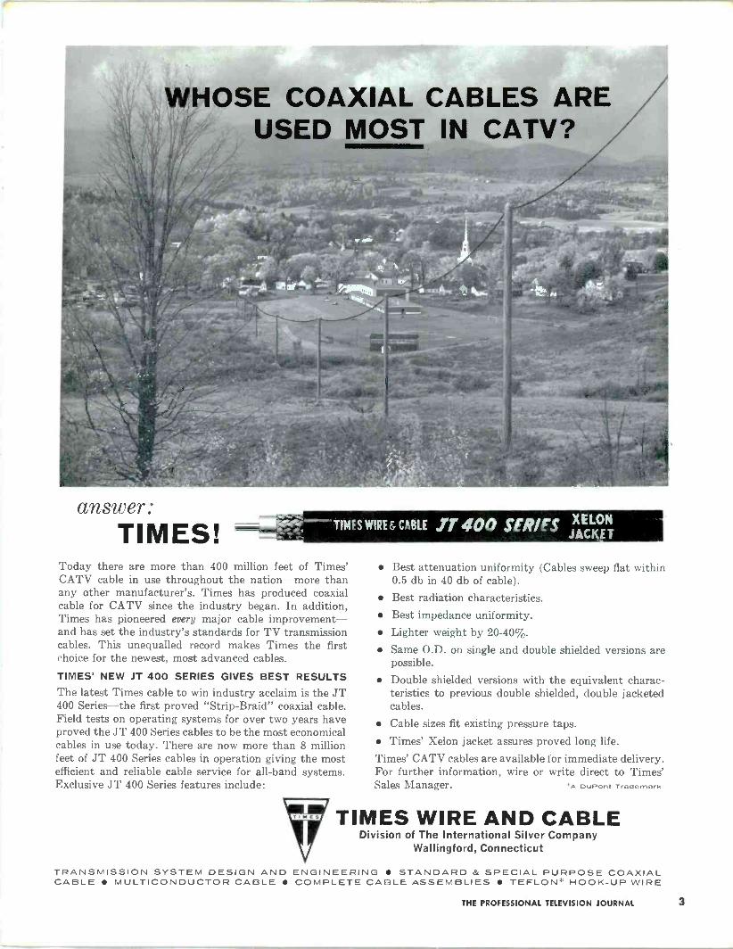
WHOSE COAXIAL CABLES ARE USED MOST IN CATV?
answer: TIMES! TIMES WIRE f CARE ,,T% 400 SER/FS XELON
JACKET
Today there are more than 400 million feet of Times' CATV cable in use throughout the nation-more than any other manufacturer's. Times has produced coaxial cable for CATV since the industry began. In addition, Times has pioneered every major cable improvement- and has set the industry's standards for TV transmission cables. This unequalled record makes Times the first choice for the newest, most advanced cables.
TIMES' NEW JT 400 SERIES GIVES BEST RESULTS The latest Times cable to win industry acclaim is the JT 400 Series-the first proved "Strip -Braid" coaxial cable. Field tests on operating systems for over two years have proved the JT 400 Series cables to be the most economical cables in use today. There are now more than 8 million feet of JT 400 Series cables in operation giving the most efficient and reliable cable service for all -band systems. Exclusive JT 400 Series features include:
Best attenuation uniformity (Cables sweep flat within 0.5 db in 40 db of cable).
Best radiation characteristics. Best impedance uniformity. Lighter weight by 20-40%.
Same O.D. on single and double shielded versions are possible.
Double shielded versions with the equivalent charac- teristics to previous double shielded, double jacketed cables.
Cable sizes fit existing pressure taps. Times' Xelon jacket assures proved long life.
Times' CATV cables are available for immediate delivery. For further information, wire or write direct to Times' Sales Manager. A DuPont Trademark
TIMES WIRE AND CABLE Division of The International Silver Company
Wallingford, Connecticut
TRANSMISSION SYSTEM DESIGN AND ENGINEERING STANDARD & SPECIAL PURPOSE COAXIAL CABLE MULTICONDUCTOR CABLE COMPLETE CABLE ASSEMBLIES TEFLON* HOOK-UP WIRE
THE PROFESSIONAL TELEVISION JOURNAL 3

PART ONE
MEET EFFINGHA1vI -A Staff Extra -
The story of how Effingham, Illinois became a recipient of CATV is not a new one Located in a deep -fringe area, this little German -American town of 8,200 people was without good television. The people in the town itself were particularly aware of the problem since they were nestled between several large metropolitan areas. Like the many other com- munities who do not have satisfactory off -the -air reception, the desire to have television was reflected in many a conversation. Such was the case in Effingham.
System technician making hook-up at top of company pole. Adjacent pole is owned by local utility company.
One of the first people to become cognizant of the, then existing situation in Effingham, was Jack Crosby, now Vice -President of Effingham TV Cable Company. This realization came quite by accident during a business trip to Effingham. Like anyone who considers television as part of daily life, Jack felt that something could and should be done. This is where the plans to start a system began to take form.
Organizing and starting a CATV system is usually not accomplished as smoothly as one might wish. Effingham was no exception. First, an agree- ment with either of the utility companies in respect to use of their poles, could not be reached. After careful consideration it was decided that the installa- tion of poles solely for the cable system's use was 4 THE PROFESSIONAL TELEVISION JOURNAL
-A Staff Extra - necessary. But, what a job! In order to support all 28 miles of cable, a total of 1,188 poles was needed. Subsequently, this number of poles was procured and set.
Antennas for the Effingham system rest way atop this large tower. Cleared area in background is local drive-in.
Another immediate problem presented itself also. This was the lack of high areas suitable for installation of the antennas and head -end equipment. There seemed to be nothing nearby that could pro- vide the necessary, all -year-round, signals that a well engineered system must have. It appeared that the best way to get good reception was to erect a large tower for this purpose. Soon a site was located just 2 miles east of town, adjacent to highway 40. Construction was begun and before very long a 540 foot tower was grazing the clouds.
A lot of thought was given to the tower installa- tion, especially where the antennas were concerned. To make sure that the top of the tower was easily accessible, an electric lift was installed to enable maintenance personnel to reach the top of the tower in as short a time as possible. For this purpose a GE
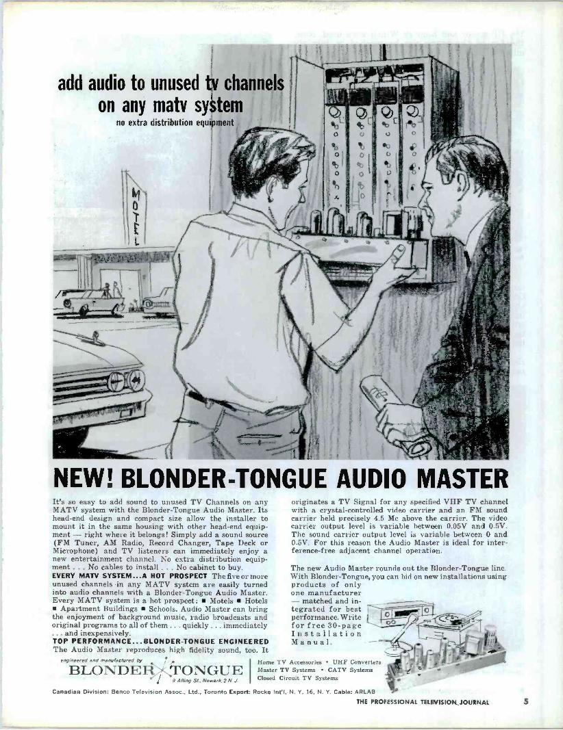
add audio to unused tv channels
on any matv system no extra distribution equipment
FL
$
NEW! BLONDER -TONGUE AUDIO MASTER It's so easy to add sound to unused TV Channels on any MATV system with the Blonder -Tongue Audio Master. Its head -end design and compact size allow the installer to mount it in the same housing with other head -end equip- ment - right where it belongs! Simply add a sound source (FM Tuner, AM Radio, Record Changer, Tape Deck or Microphone) and TV listeners can immediately enjoy a new entertainment channel. No extra distribution equip- ment ... No cables to install ... No cabinet to buy. EVERY MATV SYSTEM...A HOT PROSPECT The five or more unused channels -in any MATV system are easily turned into audio channels with a Blonder -Tongue Audio Master. Every MATV system is a hot prospect: Motels Hotels
Apartment Buildings Schools. Audio Master can bring the enjoyment of background music, radio broadcasts and original programs to all of them ... quickly ... immediately ... and inexpensively. TOP PERFORMANCE... BLONDER -TONGUE ENGINEERED The Audio Master reproduces high fidelity sound, too. It
engineered and manufactured by Home TV Accessories UHF Converters
B LO N D E RT O N G U E Master TV Systems CATV Systems
9 Ailing Sl.. Newark.2 N. J. Closed Circuit TV Systems
Canadian Division: Benco Television Assoc., Ltd., Toronto Export: Rocke Intl, N. Y. 16, N. Y. Cable: ARLAB
originates a TV Signal for any specified VHF TV channel with a crystal -controlled video carrier and an FM sound carrier held precisely 4.5 Mc above the carrier. The video carrier output level is variable between 0.05V and 0.5V. The sound carrier output level is variable between 0 and 0.5V. For this reason the Audio Master is ideal for inter- ference -free adjacent channel operation.
The new Audio Master rounds out the Blonder -Tongue line. With Blonder -Tongue, you can bid on new installations using products of only one manufacturer - matched and in- tegrated for best i performance. Write for free 30 -page Installation Manual.
THE PROFESSIONAL TELEVISION JOURNAL 5

11/Q HP motor and Ramsey Winch were used. Now, the top of the tower can be reached in just six minutes.
No, it isn't siesta time. Shown here is Phil Hays operating the tower lift. Reclining position is necessary for observation of the top of the tower.
At about this same time, construction was com- mencing on the cable system itself, by Cable TV Construction Company of Iola, Kansas. The big job ahead involved the installation of 28 miles of co -ax including the 1/2" spirofoam. aluminum shielded, trunk line. This part of the job came off without troubles. However, a lot of credit is due the installa- tion crews and their excellent public relations efforts.
The equipment selected for the system was chosen with the idea of obtaining exactly what was needed without letting the cost of the equipment
Phil Hays looking at one of the main Ime amplifiers These particular amplifiers are cable powered.
Effingham before the advent of CATV. This sea of amtennas was neces- sary for consistent T -viewing.
First bay of antennas going uF. Concrete block building in foreground houses all the head end gear Roof is reinforced with steel plate.
Stacked pieces of damaged tower. Cut guy win was responsible for damage shown here.
enter into the picture. Additionally, technical back- up was requested and received from Mr. Jim Stilwell and also Telesystem Services Corporation. This thinking all proved worthwhile when the end results were realized. To Be Continued
6 THE PROFESSIONAL TELEVISION JOURNAL

T
A AP
M A P 011
A N
:co SISTORIZ
LFI ERS AR PRODUCT
1 1
M
E N
E D
E
$68 55 Today over 4oler AMECO All -band Transistorized Amplifiers are operating in 4414"`
different systems. AMECO Transistorized Amplifiers are being installed in the 3
largest all -band systems in the U.S.... each with over 100 miles of cable. We'll furnish names upon request.
Only AMECO offers a money -back guarantee that its All -band Transistorized Equip-
ment will operate in accordance with published specifications. AMECO also gives a generous one year warranty on components.
Let us show you how the cost of AMECO Transistorized Amplifiers can be recovered in two short years in operational savings alone!
BEFORE YOU BUILD OR REBUILD BE SURE TO CONTACT AMECO. WE CAN SAVE YOU MONEY!
YOU BUY WITH CONFIDENCE WHEN YOU BUY FROM
COMMUNITY AND
CLOSED CIRCUIT
TELEVISION SYSTEMS
AMECO INCORPORATED
2949 WEST OSBORN ROAD
PHOENIX 17, ARIZONA
LEADER IN NEW DEVELOPMENTS FOR CATV
THE PROFESSIONAL TELEVISION JOURNAL 7
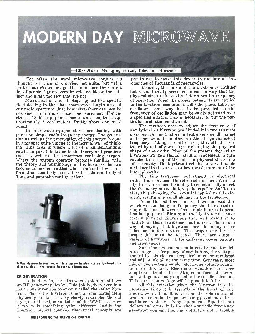
-Russ Miller Managing Editor, Television Horizons
Too often the word microwave conjurs up thoughts of a complex device, not quite, but yet a part of our electronic age. Oh, to be sure there are a lot of people that are very knowledgeable on the sub- ject and again too few that are not.
Microwave is a terminology applied to a specific field dealing in the ultra -short wave length area of our radio spectrum. Just how ultra -short can best be described in terms of exact measurement. For in- stance, 12kMc equipment has a wave length of ap- proximately 3 centimeters. Pretty short one must admit.
In microwave equipment we are dealing with pure and simple radio frequency energy. The genera- tion as well as the propagation of this energy is done in a manner quite unique to the normal way of think- ing. This area is where a lot of misunderstanding exists. In part this is due to the theory and practices used as well as the sometimes confusing jargon. Where the system operator becomes familiar with the theory and terminology of his business, he can become somewhat rattled when confronted with in- formation about klystrons, ferrite isolators, bridged Tees, and parabolic configurations.
Reflex klystron in test mount. Note square headed nut on left-hand side of tube. This is the course frequency adjustment.
RF GENERATION To begin with, the microwave system must have
an RF generating device. This job is given over to a marvelous invention commonly called the reflex klys- tron. The reflex klystron is not a complicated item physically. In fact is very closely resembles the old style, octal based, metal tubes of the WWII era. How it works is something quite different. Inside the klystron, several complex theoretical concepts are
put to use to cause this device to oscillate at fre- quencies of thousands of megacycles.
Basically, the inside of the klystron is nothing but a small cavity arranged in such a way that the physical size of the cavity determines its frequency of operation. When the proper potentials are applied to the klystron, oscillations will take place. Like any oscillator, some way has to be provided so the frequency of oscillation may be easily adjusted over a specified margin. This is necessary to put the par- ticular oscillator on -channel.
The methods used to adjust the frequency of oscillation in a klystron are divided into two separate divisions. One method will affect a very small change of frequency and the other a rather large change of frequency. Taking the latter first, this effect is ob- tained by actually warping or changing the physical shape of the cavity. Most of the present day reflex klystrons utilize a flexible strut arrangement in turn coupled to the top of the tube for physical stretching of the cavity. The klystron itself has a very flexible metal seal in this area to allow for adjustment of the internal cavity.
The fine frequency adjustment is electrical rather than physical. One electrode or element in the klystron which has the ability to substantially affect the frequency of oscillation is the repeller. Suffice to state that changing the potential applied to this ele- ment, results in a small change in the frequency.
Tying this all together, we have an oscillator which we can change in frequency about its specified range. It is not, however, this simple in actual opera- tion in equipment. First of all the klystron must have certain physical dimensions that will permit it to oscillate at those frequencies authorized. This is one way of saying that klystrons are like many other tubes or similar devices. The proper one for the proper job must be selected. There are quite a variety of klystrons, all for different power outputs and frequencies.
Since the klystron has an internal element which can change the frequency of oscillations, the voltages applied to this element (repeller) must be regulated and adjustable all at the same time. Generally, most microwave systems employ electronic voltage regula- tion for this task. Electronic regulators are very simple and trouble free. Also, some form of correc- tion voltage is usually applied to the repeller element. This correction voltage will be gone into later.
All this attention given the klystron is quite necessary since it is essentially the heart of any microwave system. It is used as the sole source of transmitter radio frequency energy and as a local oscillator in the receiving equipment. Equated into dollars and cents, it is the cheapest radio frequency generator you can find and definitely not a trouble
8 THE PROFESSIONAL TELEVISION JOURNAL

maker. Lots of them are in service with over 5000 hours of running time and they are not too expensive an item to begin with. MICROWAVE RECEIVERS
A microwave receiver is, generally speaking, like any other radio receiver. It consists of a mixer, I.F. stages, detector, and some form of amplifier after the detector. You may note the absence of any reference to an R.F. stage. At the microwave fre- quencies, any form of R.F. stage is considered to be too costly and in the long run, unnecessary. This high cost is due to the necessity of resorting to the use of Parametric amplifiers.
The biggest deviation from the usual radio re- ceiver occurs in the mixer assembly. Here, a silicon diode is used instead of a vacuum tube. This is due to the lack of satisfactory vacuum tubes capable of performing in the microwave region as mixers. A quick study of the characteristics of any diode will reveal its natural ability for mixer service.
Most all of the silicon diodes manufactured for microwave service are in cartridge form so they may be placed physically within a piece of waveguide. When installed in the proper position in a section of waveguide, the silicon diode will absorb the maxi- mum amount of incoming signal or more specifically its impedance will be a match for the incoming signal. Using the diode integrally within the wave - guide is necessitated to prevent incoming signal loss.
In order to obtain an intermediate frequency that can be fed to subsequent amplifiers, the incom- ing signal must be beat against another signal so that either a sum or difference frequency of around 30 to 90 Mc may be realized. This is the mixing pro- cess. Once again, this goes back to the inability of ordinary vacuum tubes to amplify microwave fre- quencies. So, some conversion has to be made to a frequency or frequencies that are easy to handle. Here is where the klystron is utilized.
INCOMING SIGNAL
WAVEGUIDE
RESULTANT SIGNAL
1 .
XTAL
181 L. O. SIGNAL
L. O. INJECTION
By mounting a reflex klystron somewhere in electrical relationship to the silicon diode mixer we can inject a frequency close to that of the incoming signal frequency. Result, if the injected and incoming signals are separated by, say 30 to 90 Mc, this resultant can be extracted from the diode and fed to a 30 to 90 Mc intermediate frequency amplifier. A complete receiver is now formed with only amplifica- tion necessary along with converting the intermedi- ate frequency down to video and aural frequencies in a subsequent demodulator or detector assembly.
There is one other important item, that is accur- ate control of the klystron local oscillator frequency. Without this control the local oscillator injection signal could conceivably drift far enough to put the resultant signal outside the passband of the inter- mediate frequency amplifiers. To take care of this
possibility. all microwave systems have some form of AFC (Automatic Frequency Control) . Generally all this unit consists of is an FM discriminator that produces a positive or negative output voltage when the input signal shifts about the discriminators chosen center frequency. These potentials or correc- tion voltages are then applied to the repeller element of the local oscillator reflex klystron in such a man- ner as to pull the klystron's frequency back to where the correct intermediate frequency is obtained. Es- sentially, this unit must depend upon the frequency stability of the transmitting equipment. Therefore it can be seen that the transmitter must be a stable device, frequency -wise.
In the transmitting equipment, this stability is achieved by supplying the klystron with highly regu- lated voltages and by containing the klystron in a temperature controlled environment. Some trans- mitters even incorporate AFC systems, referenced to a precision cavity, for additional stability.
Waveguide can take on all shapes and forms. Curved section in upper left-hand corner is a piece of flexible 12kMc waveguide.
WAVEGUIDE AND ANTENNAS So far the mention of waveguide and antenna
equipment has been held to a minimum because this is a separate field of its own. Theoretically, the dis- cussion and analysis of waveguide entails many pages
Business end of 12kMc waveguide showing choke joint flange.
of notes and figures. Boiled down, waveguide is as the name implies and functions much in the same manner as any balanced transmission line.
THE PROFESSIONAL TELEVISION JOURNAL 9
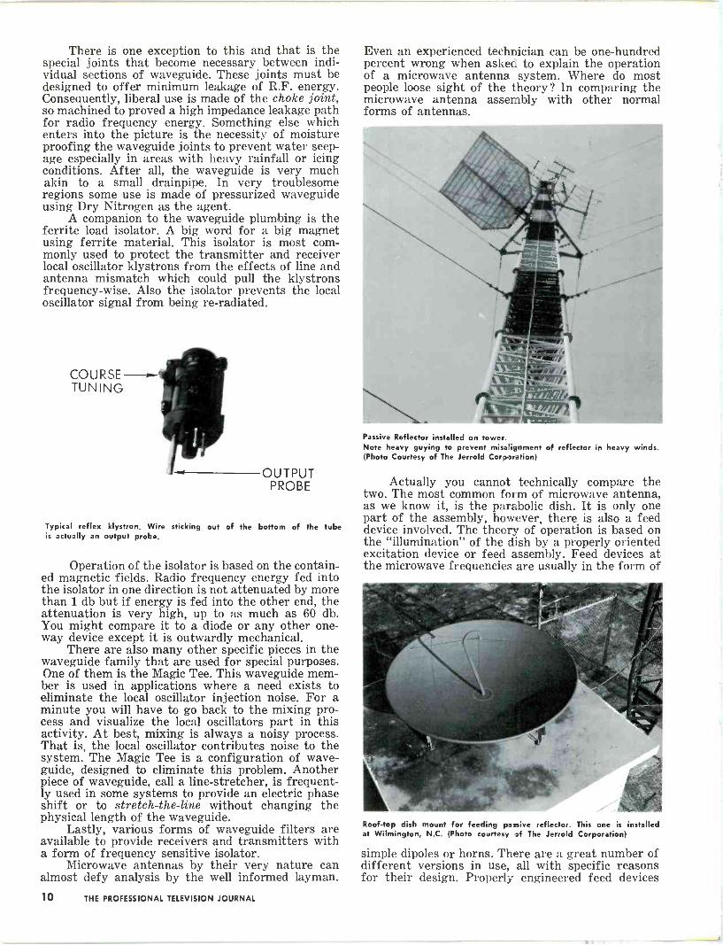
There is one exception to this and that is the special joints that become necessary between indi- vidual sections of waveguide. These joints must be designed to offer minimum leakage of R.F. energy. Consequently, liberal use is made of the choke joint, so machined to proved a high impedance leakage path for radio frequency energy. Something else which enters into the picture is the necessity of moisture proofing the waveguide joints to prevent water seep- age especially in areas with heavy rainfall or icing conditions. After all, the waveguide is very much akin to a small drainpipe. In very troublesome regions some use is made of pressurized waveguide using Dry Nitrogen as the agent.
A companion to the waveguide plumbing is the ferrite load isolator. A big word for a big magnet using ferrite material. This isolator is most com- monly used to protect the transmitter and receiver local oscillator klystrons from the effects of line and antenna mismatch which could pull the klystrons frequency -wise. Also the isolator prevents the local oscillator signal from being re -radiated.
COURSE TUNING
OUTPUT PROBE
Typical reflex klystron. Wire sticking out of the bottom of the tube is actually an output probe.
Operation of the isolator is based on the contain- ed magnetic fields. Radio frequency energy fed into the isolator in one direction is not attenuated by more than 1 db but if energy is fed into the other end, the attenuation is very high, up to as much as 60 db. You might compare it to a diode or any other one- way device except it is outwardly mechanical.
There are also many other specific pieces in the waveguide family that are used for special purposes. One of them is the Magic Tee. This waveguide mem- ber is used in applications where a need exists to eliminate the local oscillator injection noise. For a minute you will have to go back to the mixing pro- cess and visualize the local oscillators part in this activity. At best, mixing is always a noisy process. That is, the local oscillator contributes noise to the system. The Magic Tee is a configuration of wave - guide, designed to eliminate this problem. Another piece of waveguide, call a line -stretcher, is frequent- ly used in some systems to provide an electric phase shift or to stretch -the -line without changing the physical length of the waveguide.
Lastly, various forms of waveguide filters are available to provide receivers and transmitters with a form of frequency sensitive isolator.
Microwave antennas by their very nature can almost defy analysis by the well informed layman.
Even an experienced technician can be one -hundred percent wrong when asked to explain the operation of a microwave antenna system. Where do most people loose sight of the theory? In comparing the microwave antenna assembly with other normal forms of antennas.
Passive Reflector installed on tower. Note heavy guying to prevent misalignment of reflector in heavy winds. (Photo Courtesy of The Jerrold Corporation)
Actually you cannot technically compare the two. The most common form of microwave antenna, as we know it, is the parabolic dish. It is only one part of the assembly, however, there is also a feed device involved. The theory of operation is based on the "illumination" of the dish by a properly oriented excitation device or feed assembly. Feed devices at the microwave frequencies are usually in the form of
Roof -top dish mount for feeding passive reflector. This one is installed at Wilmington, N.C. (Photo courtesy of The Jerrold Corporation)
simple dipoles or horns. There are a great number of different versions in use, all with specific reasons for their design. Properly engineered feed devices
10 THE PROFESSIONAL TELEVISION JOURNAL

HOLT Advanced Engineering Presents the Model LH-BA7-4
BRIDGING AMPLIFIER This perfection engineered medium -gain bridging amplifier was designed to solve feeder-to-trunkline signal division and amplification problems. The Holt LH-BA7-4 wide -band (12 channel) amplifier will drive up to 4 feeder or trunklines from a main trunkline cable. This ruggedly built bridging amplifier is exceedingly compact, featuring a minimum of tube functions - with resultant low operating cost.
FEATURES:
Wide bandpass, channels 2 to 13, variable tilts, low and high band. Designed for continuous commer- cial service, long life, economy of operation, ex- cellent stability, matched inputs, and low power drain.
SPECIFICATIONS: Frequency range 53 to 95 and 173 to 217 Mc. Gain Ch. 6, 21 db. - Ch. 13, 25 db. Input impedance 75 ohms Output impedance 75 ohms Channels 2 to 13 Output channel 6 40 db. Output channel 13 46 db. (Channel Apart) 7, 9, 11, 13 Power consumption 45 watts Power requirements 115 V. 50 to 60 cycles Size 7 x 9 x 51/2 inches Tube complement 5 - 6EV5, 2 - 12BY7, or 5654's with
small amount of realignment
ECONOMICALLY PR!CED AT JUST $175.00
CATV Owners and Engineers: Write or call today for free consultation and data. II E&ft4/&L
v ` I COMPLETE COMMUNITY TELEVISION SYSTEMS AND ACCESSORIES
105 EAST SPRUCE STREET MAHANOY CITY, PENNA. Phone 773-1370
THE PROFESSIONAL TELEVISION JOURNAL 11
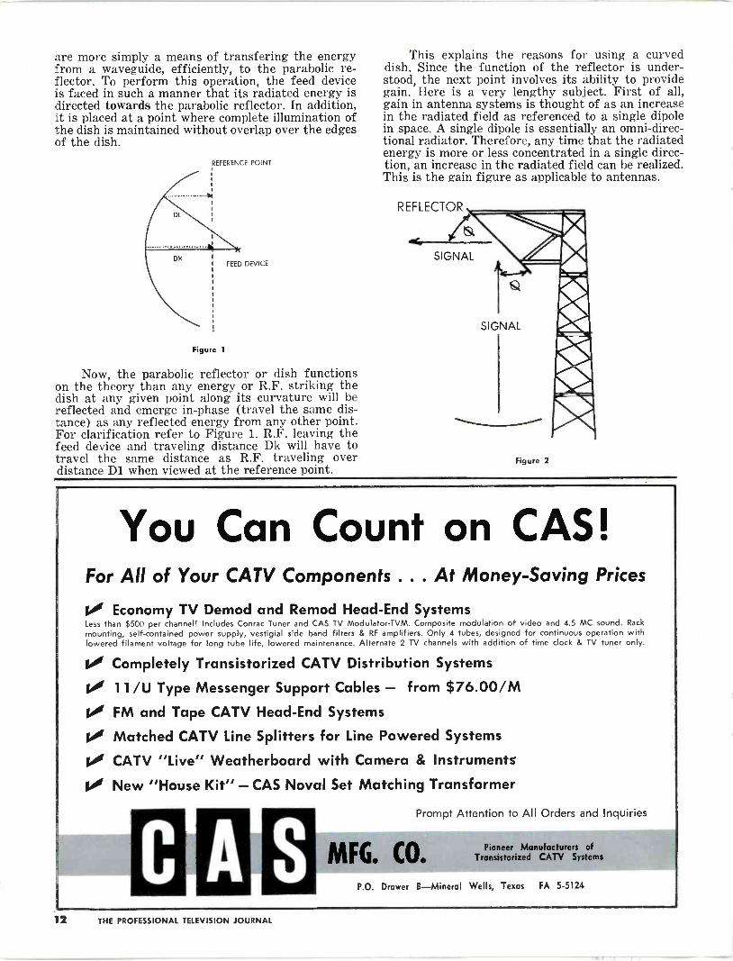
are more simply a means of transfering the energy from a waveguide, efficiently, to the parabolic re- flector. To perform this operation, the feed device is faced in such a manner that its radiated energy is directed towards the parabolic reflector. In addition, it is placed at a point where complete illumination of the dish is maintained without overlap over the edges of the dish.
REFERENCE POINT
FEED DEVICE
Figure 1
Now, the parabolic reflector or dish functions on the theory than any energy or R.F. striking the dish at any given point along its curvature will be reflected and emerge in -phase (travel the same dis- tance) as any reflected energy from any other point. For clarification refer to Figure 1. R.F. leaving the feed device and traveling distance Dk will have to travel the same distance as R.F. traveling over distance D1 when viewed at the reference point.
This explains the reasons for using a curved dish. Since the function of the reflector is under- stood, the next point involves its ability to provide gain. Here is a very lengthy subject. First of all, gain in antenna systems is thought of as an increase in the radiated field as referenced to a single dipole in space. A single dipole is essentially an omni-direc- tional radiator. Therefore, any time that the radiated energy is more or less concentrated in a single direc- tion, an increase in the radiated field can be realized. This is the gain figure as applicable to antennas.
Figure 2
You Can Count on CAS! For All of Your CATV Components ... At Money -Saving Prices
Economy TV Demod and Remod Head -End Systems Less than $500 per channel! Includes Conrac Tuner and CAS TV Modulator-TVM. Composite modulation of video and 4.5 MC sound. Rack
mounting, self-contained power supply, vestigial side band filters & RF amplifiers. Only 4 tubes, designed for continuous operation with lowered filament voltage for long tube life, lowered maintenance. Alternate 2 TV channels with addition of time clock & TV tuner only.
Completely Transistorized CATV Distribution Systems
11/U Type Messenger Support Cables - from $76.00/M FM and Tape CATV Head -End Systems
Matched CATV Line Splitters for Line Powered Systems
CATV "Live" Weatherboard with Camera & Instruments
New "House Kit" - CAS Noval Set Matching Transformer
Prompt Attention to All Orders and Inquiries
C MFG. CO. Pioneer Manufacturers of
Transistorized CATV Systems
P.O. Drawer B-Mineral Wells, Texas FA 5-512.4
112 THE PROFESSIONAL TELEVISION JOURNAL
With the parabolic dish it may be seen exactly why gain is apparent. It is concentrating R.F. energy in one narrow beam. There is a good rule of thumb to follow when thinking of the parabolic reflector in terms of beamwidth. Any increase in size results in a decrease of beamwidth or simply a higher concen- tration of energy in a specific direction.
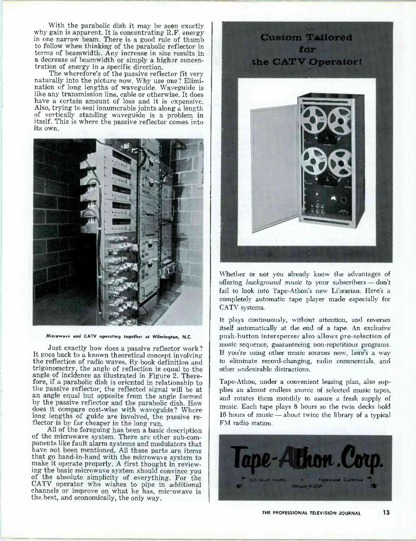
The wherefore's of the passive reflector fit very naturally into the picture now. Why use one? Elimi- nation of long lengths of waveguide. Waveguide is like any transmission line, cable or otherwise. It does have a certain amount of loss and it is expensive. Also, trying to seal innumerable joints along a length of vertically standing waveguide is a problem in itself. This is where the passive reflector comes into its own.
Microwave and CATV operating together at Wilmington, N.C.
Just exactly how does a passive reflector work ? It goes back to a known theoretical concept involving the reflection of radio waves. By book definition and trigonometry, the angle of reflection is equal to the angle of incidence as illustrated in Figure 2. There- fore, if a parabolic dish is oriented in relationship to the passive reflector, the reflected signal will be at an angle equal but opposite from the angle formed by the passive reflector and the parabolic dish. How does it compare cost -wise with waveguide? Where long lengths of guide are involved, the passive re- flector is by far cheaper in the long run.
All of the foregoing has been a basic description of the microwave system. There are other sub -com- ponents like fault alarm systems and modulators that have not been mentioned. All these parts are items that go hand -in -hand with the microwave system to make it operate properly. A first thought in review- ing the basic microwave system should convince you of the absolute simplicity of everything. For the CATV operator who wishes to pipe in additional channels or improve on what he has, microwave is the best, and economically, the only way.
Whether or not you already know the advantages of offering background music to your subscribers - don't fail to look into Tape-Athon's new Librarian. Here's a completely automatic tape player made especially for CATV systems.
It plays continuously, without attention, and reverses itself automatically at the end of a tape. An exclusive push-button intersperser also allows pre -selection of music sequence, guaranteeing non -repetitious programs. If you're using other music sources now, here's a way to eliminate record -changing, radio commercials, and other undesirable distractions.
Tape-Athon, under a convenient leasing plan, also sup- plies an almost endless source of selected music tapes, and rotates them monthly to assure a fresh supply of music. Each tape plays 8 hours so the twin decks hold 16 hours of music - about twice the library of a typical FM radio station.
THE PROFESSIONAL TELEVISION JOURNAL 13

EASY DOES IT! by David Biriey Vancouver, B.C.
Among the casualties of typhoon "Freda" was a television antenna installation owned by Northwest Television Services Limited. This installation serves about 450 homes in North and West Vancouver, B.C., and it was necessary to bring it back into service as quickly as possible.
Owing to its situation on top of Sentinal Hill in West Vancouver, a crane could not be negotiated up the steep terrain to reach it. So, owner Stan Thomas, 6535 Royal Ave., West Vancouver, hired a Hiller helicopter operated by Okanagan Helicopters Lim- ited. Because the operation was handled so gently, no further damage was sustained by the antenna, and it was back in operation .two hours after its removal.
Mr. Thomas estimated that the cost was less than half what any other method would have been, and points out that the damage which the antenna elements could have received with less gentle handl- ing, would have been more costly than the use of the helicopter.
Systems technicians just about ready to cut loose the "Freda-ized" an-
tenna array.
Damaged antenna system on its way down from the top of tie hill.
Sta n Thomas, owner of Northwest Television Systems Limited, an'i hcl'.
copter pilot Dennis Lig-it.
14 THE PROFESSIONAL TELEVISION JOURNAL

UTILITY TAKES THE JITTER (bugs) OUT OF MICROWAVE PASSIVE REFLECTORS! CATV operators and broadcasters switching to passive reflector microwave installations have discovered a common problem. Here at Utility we call it 'Jitterbugging.' You probably call it something else! Because when a 100 foot or taller tower, holding a microwave passive reflector, starts to bobble and jiggle in the wind, your micro- wave video signal gets the jitters. The picture smears and the audio warbles. The end result is dissatisfied customers and that is a problem. A microwave passive reflector is a precision instrument. It re- quires precise aiming and maximum rigidity. It simply can't move up or down, left or right, or you lose control of your microwave signal. The primary cause of microwave 'jitters,' especially in the new 12 Kmc band for CATV relay, is flexing of the tower that supports the passive reflector. Only a rock -solid rigid tower is good enough. There is no second best. And that's where Utility enters the picture. Utility towers are industry proven for both CATV and broadcasting relay installations. Utility towers stand the test of time and pass the jitterbug test with flying colors. And speaking of colors, when you are relaying color transmissions, only the very best reliability and strength will do. All Utility towers are extra -durable (A53 steel, EIA specs throughout with a 33 per- cent above recommended safety tolerance built into every tower!), All Utility micro- wave antenna or passive reflector support towers feature weather -guard moisture and element proofing, all tubing capped off to prevent moisture seepage, all welded con- struction, and heavy diagonal bracing be- tween lateral members minimizing torque twist and sway. Utility Towers are in use today in CATV installations just like yours, or the one you are planning. The photo to the left shows a Utility designed and installed tower at the Wilmington, North Carolina massive CATV system head -end, capturing the microwave signals that feed this large new system. All Utility towers carry a five year guarantee against faulty work- manship and materials, installation, engineering and design. Utility towers feature clean lines to preclude the collection of moisture, dirt and rust, minimizing tower maintenance and malfunctions. Naturally, Utility's tubing construction allows tower mounting of yagi or other receiving antenna arrays without costly modification kits.
For your next tower requirement, call the people who know about CATV and broacasting tower requirements. Call Utility Tower Com- pany for complete tower design, engineering, erection and service. At Utility - service to the customer is a premise, not just a promise.
UTILITY TOWER COMPANY 3140 N.W. 38th Oklahoma City 12, Oklahoma Phone WI 6-5551
EASTERN DIVISION - UTILITY TOWER CO. P.O. BOX 163, MAYFIELD KENTUCKY CH 7-3642
FABRICATION SALES INSTALLATION
THE PROFESSIONAL TELEVISION JOURNAL 15
FCC AND TELEVISION In a recent address before the
International Radio and Television Society, Mr. Newton N. Minow, Chairman, Federal Communications Commission, discussed several i- tems concerning the future of TV.
The following is an excerpt of his speech. "We start a new tele- vision year this month - there are some encouraging signs here and there of improved service to the public interest. There are also some startling new opportunities. I'd like to discuss them with you today. But before doing so, I want briefly to sum up this past year at the FCC. It's been an exceptionally busy year - and it has produced some tangible accomplishments. We're proud of our record."
"First, educational television. Last year we began an inquiry into the possibility of bringing VHF educational television to New York and Los Angeles. That job is now half -done. Educational TV has premiered in New York, and we hope it will quickly return to life with a sensible solution of its present labor dispute. There are events underway out west which indicate that Los Angeles will also develop educational television to meet the needs of its large com-
munity." "Our second long-range accom-
plishment : UHF television. Our recommended legislation to Con- gress giving the Commission au- thority to reauire that all television sets shipped in interstate commerce be capable of receiving all channels is now the law. Television set manfacturers are working with us in a cooperative spirit to carry out this legislation. UHF will change the face and voice of television in the present decade. It will provide exciting new opportunities for broadcasters, and it will broaden the viewer's choice in the future by lighting up 82 channels - and not only 12."
"Our UHF experimental trans- mission right here in New York, in cooperation with the City, is al- ready proving UHF's effectiveness. Tests will be concluded next month, and final results evaluated quickly. On this very day, the City of New York is making plans to take over WUHF on a permanent basis, a fruitful example of federal and municipal governments working to- gether to serve the public. We salute our own Commissioner Rob- ert E. Lee for his distinguished contribution to this proiect. At present it appears that UHF is a
technical success ; and coupled with the UHF legislation it will become a commercial success in the years ahead."
Mr. Minow then went on to ex- plain the success with the Telstar satellite and its possible uses. In closing, he said ; "History will record that the Russians were first to send a man into space. But his- tory will also record that this year the United States achieved some- thing more enduring. We were first to launch an idea into space- and ideas outlive men. That idea is to use international communica- tions for peace. That idea is to build, not a wall sealing in ignor- ance and prejudice, but a window opening toward truth and free- dom."
TV CAMERA IN KIT FORM
Craftsmen Instrument Labs, Inc., now offers a complete television camera in kit form. The new unit comes with all major components pre -assembled on the chassis to make construction easy.
No printed circuits are used in the camera. The output is adjust- able for channels 2-6 with 300 lines resolution.
Price of the camera (less Vidicon tube and lenses) is $225.00.
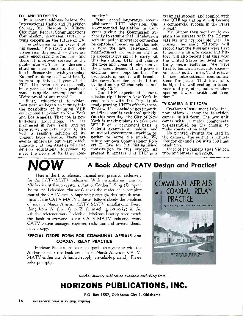
NOW A Book About CATV Design and Here is the first reference manual ever prepared exclusively
for the CATV-MATV industries. With particular emphasis on off -the -air distribution systems, Author Gordon J. King (European Editor for Television Horizons) takes the reader on a complete tour of the CATV circuit. Suprisingly enough, this English treat- ment of the CATV-MATV industry follows closely the problems of today's North America CATV-MATV installations. Every- thing from 'A' (aerials) to 'Z' (z matching networks) in this valuable reference work. Television Horizons heartily recommends this book to everyone in the CATV-MATV industry.. Every CATV system manager, engineer, technician and investor should have a copy.
SPECIAL ORDER FORM FOR COMMUNAL AERIALS and COAXIAL RELAY PRACTICE
Horizons Publications has made special arrangements with the Author to make this book available to North American CATV- MATV enthusiasts. A limited supply is available presently. Please order promptly.
Practice!
COMMUNAL AERIALS
and COAXIAL RELAY
PRACTICE by GORDON J. KING, Ass«. Brie. I.R.E. Gad T.PA.
Another industry publication available exclusively from -
HORIZONS PUBLICATIONS, INC. P.O. Box 1557, Oklahoma City 1, Oklahoma
16 THE PROFESSIONAL TELEVISION JOURNAL
BEWARE!! Quite recently one western sys-
tem was confronted with a very unusual problem. It seemed that all of a sudden the main line levels fell by approximately 20 db. The operator, not usually given to hav- ing cable problems, decided that perhaps some of the local young- sters may have been responsible. This thought occurred not by chance but by prior knowledge of youthful incidents that had hap- pened in the past.
After due deliberation, a repair team was dispatched to locate the trouble. The first point investi- gated lay slightly outside of town and in an accessible area. Nothing of interest was found, so further tracing was the order of the day. After careful searching and sub- sequent head scratching, the source of trouble was pin -pointed.
As it turned out, the offender was a man-made gadget attached firmly to the cable. The problems that were encountered in finding the "signal robber" were attributed to its very careful attachment and concealment at such a point only accessible by climbing a pole. The gadget itself consisted of a variable ceramic capacitor, a coil, and re- sistor all in series. After removing said device, everything returned to normal but the operator's nerves. Who would have thought of such a thing. NATIONWIDE CULTURAL PROGRAM
On November 29, 1962, a unique program will be presented by the National Cultural Center via clos- ed-circuit telecast. The program, which will be called "An American Pageant of the Arts," will have Mrs. Jacqueline Kennedy and Mrs. Dwight D. Eisenhower as Honor- ary Chairman. President Kennedy will also be a part of the program.
The production of the telecast and the linking of the various closed-circuit s y stems including CATV, will be handled by Theatre Network Television, Inc., 575 Madi- son Avenue, New York 22, New York. Interested system operators are asked to contact TNT for addi- tional information. KEETON NAMED MANAGER OF FLORIDA CATV SYSTEM
Joseph E. "Buster" Keeton has been named General Manager of Florida Antennavision. Inc., Ame- co's CATV system in Panama City, Florida. Keeton was formerly Chief Engineer of the system and re- places John A. Sullivan who has left the company.
CABLE gam¢
DROP Keeton, an 8 year veteran in
CATV. started as a technician in the Florence, Alabama system, then went to Vero Beach, Florida as Chief Technician of that system in 1961, and joined Florida An- tennavision in early 1962. He as- sumes his new post on October 1st, and will handle the management of the system as well as the technical end of the operation.
The Panama City system is cur- rently under construction with twenty-five miles completed which will be fired up October 15th, and another twenty-five miles ready to be activated soon. The entire sys- tem will have in excess of 100 miles of cable when completed. This will be the first operating transistor- ized all -band system in the eastern part of the country.
CANADIAN MICROWAVE Representatives of the Depart-
ment of Transport, CBC, Board of Broadcast Governors, and Canadian Association of Broadcasters met with the Deputy Minister of Trans- port recently in Ottawa for what was considered a very fruitful seminar.
One of the basic objects of the meeting was to discuss the use of microwave with CATV systems. During the discussions with those present, it was agreed that the cur- rent Canadian Radio Regulations were not in essence serving the public interest in individual situa- tions, where CATV systems were concerned. As a result more specific information was requested concern- ing the use of microwave systems.
Shortly after this meeting, the NCATA submitted a recommenda- tion that : the Radio Regulations be amended immediately to allow the
use of microwave facilities to pro- vide alternative Canadian programs in areas already served by a local Canadian TV broadcast station; and that further discussions be ar- ranged with DOT, the BBG, the broadcasters and the CATV repre- sentatives to find an acceptable formula within the framework of government policy which will allow the use of microwaves for the re- ception of U.S. programs.
NEW ETV PROPOSALS HIT SNAG Definite opposition to the use of
the 2500-2690 Mc band for educa- tional television has been voiced by a number of interests. One of the filings against adoption of the pro- posal came from the American Pe- troleum Institute.
API's Central Committee on Communication Facilities stated, "there is a basic question as to the timeliness of the Commission's pro- posals to establish a new type of private service for educational television in other than the present VHF -UHF TV spectrum." Further, "the VHF -UHF TV spectrum con- troversy has not yet been resolved, despite passage of the all -channel legislation which the Commission will soon implement." Additional comments from the committee re- commended the use of the existing allocations set aside for TV broad- casting in view of the fact that low power limited area service could be conducted on locally unallocated channels.
It was also urged that the com- mission maintain the 2500-2690 Mc band for international control and operational fixed microwave sta- tions, for which it is presently allo- cated. In commenting on use of the 1990-2110 Mc band for ETV, the API committee felt this was the ideal place for this proposed serv- ice, assuming a public need is found.
Despite the opposition to the pro- posal, wide support has been re- ceived from the various educational groups for use of the proposed frequencies.
OUCH!! We editors don't usually make
mistakes (not more than four a day) but it happens. In the Sep- tember issue of Television Horizons we erroneously listed INTEC, in an NCTA Convention photo caption, as International Electronics Cor- poration. Our apologies, Phil, we know INTEC should have been identified as Intercontinental Elec- tronics Corporation.
THE PROFESSIONAL TELEVISION JOURNAL 17
NOTE: This month we are going to bypass our
regular SYSTEM NEWS feature so we may pass on some information regarding the current trend towards the use of microwave. SYSTEM NEWS will return next month in its usual place.
MICROWAVE PROGRESS AT A GLANCE The following applications have
been tendered to the Federal Com- munications Commission within the past 60 days: (Point to Point Microwave Service)
Southwest Texas Transmission Company, proposes service from Seymour, Ga., to Warner -Robins, Ga., carrying signals of WSB-TV, WAGA-TV and WLWA-TV, all of Atlanta, Ga. (C.P.) 5kMc and 6kMc. Southwest Texas Transmission Company, proposes to carry the signals of KENS -TV. KONO-TV and WOAR-TV, all in San Antonio, Texas, to the area of Lampasas, Texas. (C.P.) 6 kMc. Laredo Microwave, Inc., proposes to install additional transmitters at Miguel, Texas, Cotulla. Texas, .and Hilltop, Texas. (C.P.) 6kMc. New York Penn Microwave Cor- poration, asked for modification of C.P. to replace existing transmitter with a K & F Electronics transmit- ter which will change emission from 15000F5 to 26000F9. Tower Communication Systems Corp., proposes to transmit signals of WLWC and WOSU (ETV) from
St. Louisville, Ohio to Coshocton, Ohio. At Coshocton, Ohio, the above mentioned signals will be relayed to Cambridge, Ohio. Simul- taneously, a single channel of serv- ice will be power split and the signal of WLWC transmitted to Shanesville, Ohio. The station at Coshocton is also the terminal re- ceiver point for 3 channels of service from Shanesville, Ohio re- laying the signals of stations KYW, WEWS and WJW of Cleveland, Ohio. At Shanesville, Ohio, the 3 above mentioned channels of serv- ice will be transmitted to Coshoc- ton, Ohio. Two channels of service will be used to relay the signals of WEWS and WLWG to New Phila- delphia, Ohio. Shanesville is the initial pick-up point of the signal of WEWS. The signal of WLWC is repeated from the initial pick-up point at St. Louisville, Ohio. At the repeater receiver site at New Philadelphia, Ohio, the two above mentioned signals will be relayed to the terminal receiver site at Dennison by means of a passive reflector. (C.P.) 6kMc.
TelePrompTer Transmission of New Mexico, proposes to carry the signals of KTVU, KRON-TV, KPIX. KGO-TV, and KQED all of San Francisco. California from Bayshore, California to Mt. Loma Prieta, California. (C.P.) 6kMc.
Microwave Communications, Inc., Philadelphia, Penn., proposes to re- lay the signals of stations WTTV,
JdaViouu,cibtg
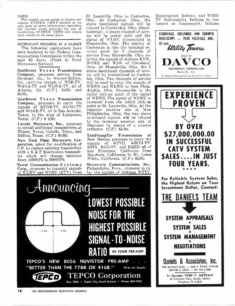
äik LOWEST POSSIBLE
NOISE FOR THE
HIGHEST POSSIBLE
SIGNAL - TO - NOISE
RATIO IN YOUR PRE -AMP
TEPCO'S NEW 8056 NUVISTOR PRE -AMP . .
"BETTER THAN THE 7788 OR 416B." Write for Details
TEPCO Corporation Box 2065 Rapid City, South Dakota Phone 343-7200
Bloomington, Indiana, and WISH - TV Indianapolis, Indiana to cus- tomers at Logansport, Indiana.
STARKVILLE, COLUMBUS AND CORINTH,
MISSISSIPPI - PLUS YALEVILLE, ARK.,
All use: r SOLD BY
DAVCO ELECTRONICS CORPORATION
Batesville, Ark.
Southwest Representatives for Utility Tower
EXPERIENCE PROVEN
BY OVER $27,000,000.00 IN SUCCESSFUL CATV SYSTEM
SALES... . IN JUST FOUR EARS.
For Reliable System Sales, the Highest Return on Your Investment Dollar, Contact:
THE DANIELS TEAM
SYSTEM APPRAISALS
SYSTEM SALES
SYSTEM MANAGEMENT
NEGOTIATIONS
Daniels & Associates, Inc. THE DANIELS BLDG. - 2430 E. THIRD AVENUE
DENVER 6, COLO. - PH. DU 8-5888
In Canada: FRED T. METCALF 25 Crestwood Place, Guelph, Ontario
Telephone TA 2-2030
18 THE PROFESSIONAL TELEVISION JOURNAL

The following actions have been taken by the Federal Communica- tions Commission within the past 60 days:
East Texas Transmission Company, granted C.P. for 6kMc system. Proposes to provide a 3 channel service to bring the signals of KRLD-TV, Dallas, Texas, KFJZ- TV and WBAP-TV, Fort Worth, Texas into Palestine, Texas for service to a CATV system opera- ting in that community. This will be accomplished by extending its present system beyond its present drop-off point at Jacksonville, Texas which now becomes a relay point.
Mid -Kansas, Inc., granted C.P. for 6kMc system. Proposes by means of a power split at this station (Abilene, Kansas), to furnish a 3 channel service to bring the signals of KAKE-TV. KARD-TV, and K T V H -T V, Wichita -Hutchinson, Kansas into Clay Center and Salina, Kansas for service to its present CATV customers.
Gene Autry and Loyd Sigmon (Autry - Sigmon Communications), Los Angeles, California, granted C.P. for 6kMc system. Proposes to provide a 7 channel service to bring the signals of stations KNXT, KRCA. KABC-TV, KHJ-TV, KTTV and KCOP, Los Angeles, California into Morro Bay, California for service to a CATV system in that community.
NEW CABLE FROM VIKING Viking Cable Company has just
recently introduced a new strip - braid coaxial cable with built-in messenger. The new cable, which is available in single or double shielded types, has a low loss foam di -electric and exhibits exception- ally low attenuation characteristics throughout the TV spectrum.
"We built the VK -108 cable to be rugged and added the galvanized steel messenger cable to substanti- ally reduce the overall costs repre- sented in installation of a separate messenger and associated coaxial cable," says Arthur Baum, Presi- dent of Viking Cable Company. "Also, the cable is lower in cost than buy i n g messenger wire separately."
Viking Cable Company also has special pressure taps available to accommodate coaxial cables with built-in messenger wire. MICROWAVE FILINGS
It is very evident that microwave is here to stay. The increased num- ber of filings for Point to Point Microwave Radio Service more than bears this out. We might ask our- selves why, at this time, so many applications have been submitted ? It is a simple matter of service and the general attitude of the CATV'ers themselves.
In the history of CATV there is not one instance where progress has not been carried forth when techniques and equipment were available to allow expansion.
s _ _m O Heavy Duty Quads and Yagis Designed by SITCO for Translator off -the -air pickup, Community TV and extreme fringe area requirements.
creo wmae &MEW FADTENEM
:z `./-
Write for Free SITCO Catalog
The SITCO Models 94 and 102 Quad Mount Antenna Arrays are designed to produce high gain, high front -to -back ratio and large aperture to weak signals. A completely bal- anced system which re- duces noise pick-up and greatly improves the signal-to-noise ratio.
NOW, all SITCO element ends are machined to re- duce static leakage. The signal-to-noise ratio is in- creased at sites where signal levels are low.
Model No. 94 -HD 32 -element Quad Channels 5 or 6
Model No. 102 -HD 48 -element Quad For all hi -band channels
SIMPLICITY TOOL COMPANY 2850 NORTH MISSISSIPPI PORTLAND 12, OREGON
Wishing for a
field strength and wattmeter
sufficiently small to be portable, accurate enough to use in lab,
ruggedly built for field use and on top of all that, inexpensive?
Your wish is granted!
It's the
model FSP-3
Dimensions: 51" x 111/4" x 73/4" 0 Weight: only 10 lbs. including batteries D Sensitivity: 5 microvolts minimum readable signal or 60 m/v full scale with sensitivity control at maximum Selectivity: all spurious re- sponses including image more than 80 db down, 4.5 Mc/s or more away from selected frequency Battery Life: 180 hours con- tinuous or better than 3 hours per week for one year.
8ENCO
Television Associates Ltd.
27 Taber Road, Rexdale, Ontario, CANADA
In U.S.A. Blonder -Tongue Laboratories, Inc. 9 Ailing Street, Newark 2, N.J.
THE PROFESSIONAL TELEVISION JOURNAL 19
Gentlemen: "Enclosed is my check for 1 year sub-
scription. Please pass on the following questions to the right department.
1. How soon will UHF be in effect in a big way?
2. What is going to happen to the viewer who only gets fair VHF reception in their rather poor signal areas?
3. Do you feel this will be a real boost to CATV operators?"
Erling O. Wing TV by Erling P.O. Box 392 Walnut Creek, California
Mr. Wing: To start off with, see the excerpt of
Mr. Newton Minow's address to the International Radio and TV Society in answer to your first question. His address appears elsewhere in this issue. On your second question, all results to date would indicate that the same condi- tion will probably exist that exists now. To just what extent their reception
would be affected depends on a great number of technical variables. Lastly, I would like to quote Ike Blonder in re- sponse to question three. This statement is one that was given at the NCTA con- vention in San Francisco, June, 1961.
"I feel the CATV industry has not yet awaken to the fact that someday, soon, the entire allocations structure in this nation will be changing. Television will move to all UHF, and areas which are now doing without local television may suddenly find themselves with TV. BUT, by the same token, there will be many - many regions where passable VHF re- ception is now passable, where future off -the -air UHF reception will not be possible. Thus I see the CATV picture as one of change, with new "white areas" where CATV will have to move in to assure continued video reception, and "old white areas" where CATV will suddenly have substantial off -the -air reception competition."
The Editor
CATV Man Wanted .. .
to represent manufacturer of CATV cable and equipment. All replies held in strictest confidence. (Our employees know about this ad.) Write - Box W-10, Tele- vision Horizons. SELLING SERVICE??
Watch out who you recommend as a competent TV serviceman. One recent incident, where a CATV system business office recom- mended a particular TV service agency, resulted in charges of dis- criminatory practices from the local service association.
The system in question immedi- ately answered the charges with a statement that implied they be- lieved all but one of the local service
bring your picture in
out of the snow with
CECO'S UHF/VHF
PREAMPLIFIERS Ceco's ultra -low noise UHF and VHF preamplifiers effectively
double transmitter power at the receiver site, eliminating entirely or reducing significantly snowy TV reception. These rugged, com-
pact, single channel units have self-contained power supplies .. .
advanced tube types and other com- ponents for long, trouble -free life. They require no cooling devices, are housed in easily mounted, weatherproof alu- minum enclosures.
Ceco manufactures complete equipment for TV cable systems.
Write for complete information.
Community
Engineering
Corporation STATE COLLEGE, PENNSYLVANIA
Telephone AD 8-2461 Area Code 814
EVERYTHING FOR CATV!
FAST DELIVERIES FROM STOCK
DAVCO ELECTRONICS CORPORATION
Phone RI 3-3816 Batesville, Ark.
shops were incapable of providing good service. This was all the local service association needed to fuel the fire, whereupon, they immedi- ately boycotted all their customers who were system subscribers. They then followed up this action with newspaper ads explaining the situa- tion to the general public.
Naturally, the results were dis- astrous. The CATV system busi- ness office was flooded with calls asking what was going on. Also, those customers who had been boy- cotted by the local service shops vented their wrath at the system operators. At this stage little could be done except to try and justify the claims made. After many telephone calls and plenty of leg work, enough complaints about service and the subsequent charges for service was collected by the CATV system crews assigned this task. It seemed at this point that a meeting with the local association officials was indeed in order.
During the meeting, which was one surrounded with a hostile at- mosphere, all the collected informa- tion was presented to the associa- tion representatives on a purely factual basis. Surprisingly enough, things took a turn for the better when the association personnel an- nounced that the claims were just and certainly some effort would have to be made on their part to improve public relations. At this point the system representatives suggested that the two groups work from here on out as one body to resolve all future problems. This method was unanimously adopted by all present.
Has this approach worked ? Yes, things are pretty well straightened out now. There is, however, irre- parable damage still existing that only time will heal. The CATV sys- tem operators now wish that they had left their subscribers to their own problems. But, it has probably worked out for the best. It is cer- tainly an admirable thing to be conscientious about ones services but only to a point.
20 THE PROFESSIONAL TELEVISION JOURNAL
I TO ANTENNA
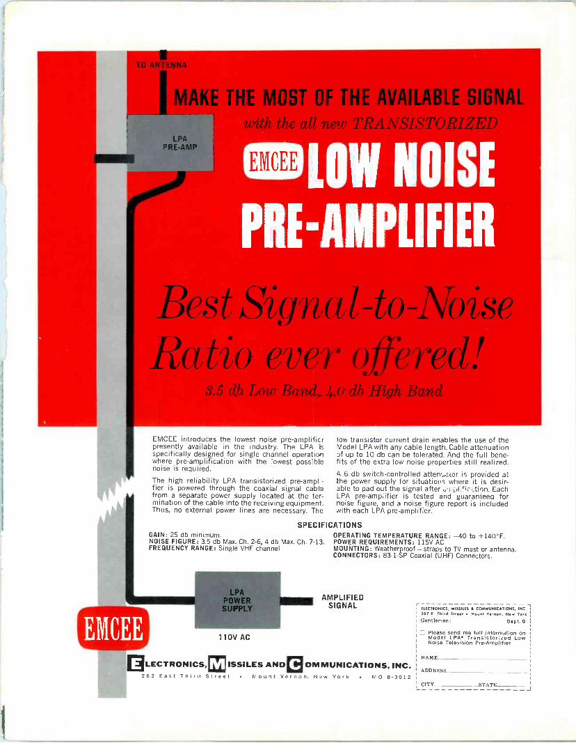
MAKE THE MOST OF THE AVAILABLE SIGNAL
LPA PRE -AMP
TRANSISTORIZED
S LOW OISE
PI -A PLIFIER
Bes t ,Signa l -to -Noise Ratio ever offered!
O db High Band
EMCEE introduces the lowest noise pre -amplifier presently available in the industry. The LPA is specifically designed for single channel operatio- where pre -amplification with the lowest possib noise is required.
The high reliability LPA transistorized pre-ampl -
fier is powered through the coaxial signal cabla from a separate power supply located at the ter- mination of the cable into the receiving equipment. Thus, no external power lines are necessary. The
low transistor current drain enables the use of the Model LPA with any cable length. Cable attenuation if up to 10 db can be tolerated. And the full bene- fits of the extra low noise properties still realized.
4 6 db switch -controlled atten:.ator is provided at the power supply for situations where it is desir- able to pad out the signal after i:.ri fi: <tinn. Each LPA pre -amplifier is tested and guarantee° for noise figure, and a noise figure report is included with each LPA pre -amplifier.
SPECIFICATIONS GAIN: 25 db minimum. OPERATING TEMPERATURE RANGE: -40 to +140°F. NOISE FIGURE: 3.5 db Max. Ch. 2-6, 4 db Max. Ch. 7-13. POWER REQUIREMENTS: 115V AC FREQUENCY RANGE: Single VHF channel MOUNTING: Weatherproof - straps to TV mast or antenna.
CONNECTORS: 83 -1 -SP Coaxial (UHF) Connectors.
OD LPA
POWER SLIPP
110V AC
©LECTRONICS,©ISSILES AND 262 East Third S
AMPLIFIED SIGNAL
OMMUNICATIONS, INC. reet Mount Vernon, New York MO 8-3012
ELECTRONICS, MISSILES & COMMUNICATIONS, INC-I 262 E. Third Street Mount Vernon, New York
Gentlemen: D ep t. 0
El Please send me full information on Model LPA* Transistorized Low Noise Television Pre -Amplifier
NAME
A DDRFSS
CITY STATE J

LATEST DEVELOPMENT IN TAP -OFF DESIGN!
SUPER FASTE TAP -OFF BLOCK
Double clamp accommodates all standard messengers.
Grounding assured by built-in waterproof neoprene gasket and silver plated brass ground- ing pins.
Drop -Line stress reduced by
industry's most positive sure lock strain relief.
Single bolt installation with rugged 2 -piece block lets you install without disassembling.
Seepage eliminated by new vertical position of attenuator -now the best on the market today.
All this plus the same old reliable FASTEE inserts, shaped for low shunt capacity and with pre -lubricated cones, combine to reduce installation time and guarantee depend- able service. That's why you should contact your distributor or Entron sales department for an exclusive analysis of your tap -off problem.
WWI
FILL IN THIS COUPON FOR FREE SAMPLE!
Please send me a FREE Sample of your new Entron Tap -Off (Includes Insert). l understand l Am Under No Obligation Whatsoever.
NAME
Position
Company Name
Company Address
City State
Check Your Choice: FTC 405 (single shield) FTC 460 (double shield)
J 2141 INDUSTRIAL PARKWAY, SILVER SPRING, MARYLAND TEL. 622-2000
Related Documents