ORIGINAL PAPER The Synergistic Effects of Cavitation Erosion–Corrosion in Ship Propeller Materials J. Basumatary 1 • M. Nie 1 • R. J. K. Wood 1 Received: 15 December 2014 / Revised: 3 March 2015 / Accepted: 5 March 2015 / Published online: 25 March 2015 Ó Springer International Publishing AG 2015 Abstract Synergy tests were performed for two most common propeller materials, duplex stainless steel (DSS) and nickel aluminium bronze (NAB), by means of an indirect ultrasonic vibratory system. Tests were conducted for pure cavitation erosion in distilled water, pure corrosion using in situ electrochemistry under 3.5 % NaCl solution and a combination of cavitation erosion–corrosion to un- derstand the overall synergism existing between the two. The results were analysed using gravimetric as well as volumetric analysis. Alicona and Talysurf were employed for the surface topography, and scanning electron micro- scope was used to see the microstructural morphologies of the samples under different conditions. As a result, the electrochemical tests held at open circuit potential showed that, although DSS exhibited higher resistance to corrosion under seawater alone, NAB exhibited much higher resis- tance to corrosion when subjected to cavitation. From the experiments conducted, it was concluded that synergy had measurable impact on the cavitation erosion–corrosion of both NAB and DSS. NAB was found to be more suscep- tible to erosion under both the conditions as compared to DSS with prominent selective cavitation erosion of alpha phase in the microstructure. The overall synergism of NAB was found to be higher than that of DSS. Keywords Cavitation Cavitation erosion Cavitation erosion–corrosion Propeller materials Nickel aluminium bronze Duplex stainless steel 1 Introduction The simultaneous existence of mechanical erosion and electrochemical corrosion is a common scenario for engi- neering alloys used in marine environments, such as pump impellers and valves. The situation is further complicated by the fact that the effects of erosion and corrosion are in general not additive owing to the interaction between them. The overall damage arising from erosion and corrosion including the interaction between them is termed cavitation erosion–corrosion. The relative significance of corrosion, erosion and the interaction between them depends on the material and the environment system [1]. The nature of the interaction is determined by a number of factors, the more important ones being the passivity of the metal surface, the adherence of the corrosion product, the metallurgical state of the metal, the significance of the diffusion of dissolved oxygen, the presence of aggressive ions and the intensity of cavitation. These factors would determine the mode of corrosion and the rate of erosion–corrosion loss [2–4]. Several studies have been conducted and proven the ex- istence of synergy between cavitation erosion and corrosion, and that this synergy can have a significant effect on the cavitation behaviour of the test materials [5–12]. Vyas and Hansson [1] conducted the ultrasonic vibrating cavitation on stainless steel (SS) in 3.5 % NaCl solution, and they found that the degree of intergranular corrosion of the sensitized SS increased with increasing cavitation density. They con- firmed that for stainless steels due to the existence of the passive film, cavitation could accelerate or decelerate cor- rosion, depending on the intensity of cavitation and the metallurgical state of the SS specimens. Tomlinson and Talks [3] studied the cavitation erosion–corrosion of various types of cast iron in 3 % sodium chloride solution and found that the fractional weight loss due to pure corrosion ranged & J. Basumatary [email protected] 1 National Centre of Advanced Tribology in Southampton (nCATS), University of Southampton, Southampton, UK 123 J Bio Tribo Corros (2015) 1:12 DOI 10.1007/s40735-015-0012-1

Welcome message from author
This document is posted to help you gain knowledge. Please leave a comment to let me know what you think about it! Share it to your friends and learn new things together.
Transcript

ORIGINAL PAPER
The Synergistic Effects of Cavitation Erosion–Corrosion in ShipPropeller Materials
J. Basumatary1• M. Nie1
• R. J. K. Wood1
Received: 15 December 2014 / Revised: 3 March 2015 / Accepted: 5 March 2015 / Published online: 25 March 2015
� Springer International Publishing AG 2015
Abstract Synergy tests were performed for two most
common propeller materials, duplex stainless steel (DSS)
and nickel aluminium bronze (NAB), by means of an
indirect ultrasonic vibratory system. Tests were conducted
for pure cavitation erosion in distilled water, pure corrosion
using in situ electrochemistry under 3.5 % NaCl solution
and a combination of cavitation erosion–corrosion to un-
derstand the overall synergism existing between the two.
The results were analysed using gravimetric as well as
volumetric analysis. Alicona and Talysurf were employed
for the surface topography, and scanning electron micro-
scope was used to see the microstructural morphologies of
the samples under different conditions. As a result, the
electrochemical tests held at open circuit potential showed
that, although DSS exhibited higher resistance to corrosion
under seawater alone, NAB exhibited much higher resis-
tance to corrosion when subjected to cavitation. From the
experiments conducted, it was concluded that synergy had
measurable impact on the cavitation erosion–corrosion of
both NAB and DSS. NAB was found to be more suscep-
tible to erosion under both the conditions as compared to
DSS with prominent selective cavitation erosion of alpha
phase in the microstructure. The overall synergism of NAB
was found to be higher than that of DSS.
Keywords Cavitation � Cavitation erosion � Cavitation
erosion–corrosion � Propeller materials � Nickel aluminium
bronze � Duplex stainless steel
1 Introduction
The simultaneous existence of mechanical erosion and
electrochemical corrosion is a common scenario for engi-
neering alloys used in marine environments, such as pump
impellers and valves. The situation is further complicated
by the fact that the effects of erosion and corrosion are in
general not additive owing to the interaction between them.
The overall damage arising from erosion and corrosion
including the interaction between them is termed cavitation
erosion–corrosion. The relative significance of corrosion,
erosion and the interaction between them depends on the
material and the environment system [1]. The nature of the
interaction is determined by a number of factors, the more
important ones being the passivity of the metal surface, the
adherence of the corrosion product, the metallurgical state
of the metal, the significance of the diffusion of dissolved
oxygen, the presence of aggressive ions and the intensity of
cavitation. These factors would determine the mode of
corrosion and the rate of erosion–corrosion loss [2–4].
Several studies have been conducted and proven the ex-
istence of synergy between cavitation erosion and corrosion,
and that this synergy can have a significant effect on the
cavitation behaviour of the test materials [5–12]. Vyas and
Hansson [1] conducted the ultrasonic vibrating cavitation on
stainless steel (SS) in 3.5 % NaCl solution, and they found
that the degree of intergranular corrosion of the sensitized
SS increased with increasing cavitation density. They con-
firmed that for stainless steels due to the existence of the
passive film, cavitation could accelerate or decelerate cor-
rosion, depending on the intensity of cavitation and the
metallurgical state of the SS specimens. Tomlinson and
Talks [3] studied the cavitation erosion–corrosion of various
types of cast iron in 3 % sodium chloride solution and found
that the fractional weight loss due to pure corrosion ranged
& J. Basumatary
1 National Centre of Advanced Tribology in Southampton
(nCATS), University of Southampton, Southampton, UK
123
J Bio Tribo Corros (2015) 1:12
DOI 10.1007/s40735-015-0012-1

from 1 to 10 %, while that due to corrosion-induced erosion
ranged from 16 to 90 %. Between 1998 and 2006, Kwok
C.T. performed several experiments on laser-treated metals
such as austenitic steel alloy and NiCrSiB alloy in 3.5 %
NaCl solution. It was found that the synergism was re-
sponsible for 50–70 % of total loss for laser-alloyed 1050
steel specimen and 20 % for laser surface-alloyed 316 SS
specimen, and the cavitation erosion–corrosion resistance
was noticed improved for 1050 and 316 SS, respectively
[13–18]. In 2000, Kwok, Chen and Man conducted another
ultrasonic vibrating cavitation at 20 kHz on nine different
kinds of metals including cast irons and SS under 3.5 %
NaCl solution [19]. From the experimental results, it was
found that synergism had a significant effect on mass loss
with up to 85 % total damage. This synergy effect was found
to be due to several factors such as impact of corrosive
solution, the material property and also the type of materials
itself. The most significant impact was found at a mild
corrosive environment [4, 20–22].
Few studies have also been conducted on ship propeller
materials such as SS, copper alloys, manganese bronze and
nickel aluminium bronze (NAB) among others. A synergy
experiment conducted by Kwok, Cheng and Man ranked
austenitic (304) stainless steels to have very high cavitation
erosion resistance than austenitic 316 SS owing to its
higher martensitic transformability and work hardenability
and lower stacking fault energy of 25 mJ m-2 [23]. They
also concluded that materials with high corrosion resis-
tance such as copper alloys also displayed higher resistance
to the erosion–corrosion synergy. They established that the
effect of cavitation on corrosion behaviour particularly
depended on two main effects of cavitation, corrosion film
detachment and increase of mass transport [10]. Several
cavitation corrosion tests were conducted by Al-Hashem,
Caseres, Riad and Shalaby on propeller materials like cast-
nickel aluminium bronze (NAB) and duplex stainless steel
(DSS) in seawater using 20-kHZ ultrasonic vibrator under
free corrosion and cathodic protection conditions, and they
found that for DSS, the rate of mass loss was reduced by
19 % under cathodic protection, slightly reducing the
subsequent number of cavities as a result. The attack was
seen to be concentrated in the austenite phase but was
eventually seen to spread to the ferrite phase. This was
associated with ductile tearing, cleavage-like facets, river
patterns and crystallographic steps at later stages. Speci-
men cross-sections revealed microcracks at the bottom of
the cavities initiating from the ferrite matrix with crack
propagation impeded by the austenite islands, branching
along the parallel slip systems. They also observed an ac-
tive shift in the free corrosion potential by about 140 mV
when cavitation was applied, with a slight increase in the
cathodic and anodic currents, shifting the corrosion po-
tential in the noble direction by 75 mV [24].
However, their cavitation corrosion test of NAB showed
a decrease of rate of mass loss by 47 % under cathodic
protection and a shift in corrosion potential in the active
direction by 70 mV. This could be attributed to the cush-
ioning of bubble collapse by cathodic gas and elimination
of electrochemical dissolution. They also observed under
the optical and scanning electron microscopy that NAB
seemed to suffer from selective corrosion of the copper-
rich a phase at its boundaries with intermetallic j pre-
cipitates, while the j precipitates and precipitate-free areas
did not suffer corrosion. Also, it was found that selective
corrosion was enhanced by cavitation erosion. Under only
cavitation, large cavities were found with a–j grain-
boundary corrosion around the pit edge, whereas, in the
presence of cathodic protection, the number of cavities was
found to increase but the grain-boundary attack was seen to
be absent. They also found microcracks of 5 l to 10 lm
length were observed in the a phase adjacent to j pre-
cipitates along the cross section of the material. Selective
phase corrosion and cavitation stresses were implicated as
the causes of cracking [25, 26].
However, despite all the studies done so far, the study on
synergistic effects existing between erosion and corrosion
were usually carried out under different conditions by
different authors, making results difficult to compare.
Synergy can be measured in terms of two most common
factors, mass loss incurred by combined contribution of
erosion and corrosion or the mean depth of penetration
(MDP) rate. The equation for synergy is commonly written
as
T ¼ S þ E þ C: ð1Þ
Here, T is the total mass loss or overall cavitation ero-
sion–corrosion rate, C is the pure corrosion contribution; E
is the pure erosion contribution, and S is the combined
contribution due to synergistic effect. S can be also rep-
resented as in Eq. 2:
S ¼ T � ðE þ CÞ ¼ DE þ DC; ð2Þ
where DE = corrosion-enhanced erosion and DC = ero-
sion-enhanced corrosion. The present study was carried out
in order to understand the existence of synergism between
erosion and corrosion in the overall cavitation erosion–
corrosion damage of the two most commonly used ship
propeller materials, 2205 DSS and CuAl10Ni cast-NAB in
3.5 % NaCl solution at room temperature [10].
2 Experimental Method
The experiment for synergy between cavitation erosion–
corrosion was conducted using indirect ultrasonic cavita-
tion rig. Although several tests have been conducted in the
12 Page 2 of 12 J Bio Tribo Corros (2015) 1:12
123

past using an ASTM G-32 direct cavitation system where a
round sample disc is threaded into the probe tip; however,
the contact between the sample material and the probe
material could render electrochemical analysis difficult and
could cause possible galvanic corrosion between the two
resulting in either over- or under-evaluation of the corro-
sion-induced loss, and hence an indirect ultrasonic vibra-
tory cavitation system was used instead of the direct
system. Ultrasonic vibratory transducer UIP1000hd with a
sonotrode horn made from titanium of diameter 15.9 mm
was used for the cavitation experiment at a frequency of
20 kHz and a peak-to-peak amplitude of 80 micron at room
temperature of 17 ± 0.5 �C. The test samples were placed
under an ultrasonic transducer with a vibrating probe of
diameter 15.9 mm kept at a distance of 2 mm above the
specimen surface for 1 h. The samples were tested for
cavitation erosion in 5 L of distilled water, for cavitation
corrosion in 5 L of 3.5 % NaCl aqueous solution using
in situ electrochemistry kept at open circuit potential
(OCP) and finally for cavitation erosion–corrosion in 3.5 %
NaCl solution with in situ electrochemistry kept at OCP.
Precision weighing machine (±0.01 mg) was used to
measure the gravimetric mass loss of each sample. Alicona
measurements were taken using Alicona 3D optical pro-
filometer to measure the volumetric mass loss of the
samples along with surface roughness of cavitated regions
and compared with each other, as well as surface topog-
raphy. Form Talysurf 120 L was also employed to capture
the overall surface roughness. Scanning electron mi-
croscopy was used to analyse the different microstructures
obtained under different conditions and cavitation envi-
ronment to compare the samples.
2.1 Propeller Materials Used
The materials used were 25 9 25-mm specimen samples of
2205 DSS and NAB with a thickness of 5 mm held under the
horn with Perspex fixture for the indirect cavitation process.
The surfaces of all the test samples were wet-polished using
1200 and 4000 grit silicon carbide (SiC) abrasive papers.
Table 1 gives the mechanical properties of the ship propeller
materials used for the experiment, and Table 2 gives the
chemical compositions of the test materials used.
Ship propellers work in a very harsh environment under
the sea, i.e. in a corrosive environment, for the majority of
their lifetime. Hence, it is only reasonable for the chosen
test materials to be based not only on their high tensile
strength but also on their resistance to corrosion. DSS has
been well known for its high resistance to intergranular
corrosion, hence they serve as great raw material for
building the propellers. DSS used for the experiment was
type 2205. Mechanical properties were 774 MPa ultimate
tensile strength, 542 MPa yield strength with 34 % elon-
gation and 233 Hv Vickers hardness. The microstructure
consisted of a ferritic matrix with islands of austenite
grains as shown in Fig. 1. DSS displays properties char-
acteristic of both austenitic and ferritic stainless steels due
to their composite microstructure and are found to be, in
most cases, tougher than ferritic SS and have higher
strength as well as corrosion resistance as compared to the
generally used engineering austenitic SS [27].
Similarly, NAB is another lightweight conventional ship
propeller alloy used for the experiment for its high-strength
mechanical properties with an ultimate tensile strength of
650 MPa, yield strength of 270 MPa and 170 Hv Vickers
hardness. It is also considered to exhibit excellent cavita-
tion resistance against the seawater [26]. NAB has high
ability to retain its original smooth machined surface over a
long period of time, thereby retaining its high efficiency
factor, and it also has the ability to resist failure under
impact when notched, contributing greatly to its value as a
Table 1 Mechanical properties of the materials used for the research
Propeller material alloys Ultimate tensile
strength (MPa)
Yield
strength (MPa)
Elongation
(%)
Density
(g/cm3)
Hardness
(Hv)
2205 (duplex stainless steel) 774 542 34 7.8 233
Nickel aluminium bronze (NAB) 650 270 18 7.65 170
Table 2 Chemical compositions of the materials used for the
research
Material alloys
composition (wt.%)
Nickel
aluminium bronze
Duplex stainless
steel (2205)
C (%) – 0.024
Mn (%) 1.07 1.83
Ni (%) 4.73 5.66
Cr (%) – 22.7
Mo (%) – 3.01
Cu (%) – 0.22
Sn (%) \0.01 –
Al (%) 9.39 –
Pb (%) 0.01 –
Zn (%) 0.11 –
Fe (%) 4.53 –
W (%) – 0.02
N (%) – 0.02
J Bio Tribo Corros (2015) 1:12 Page 3 of 12 12
123

propeller material [26]. The microstructure of NAB is more
complex than DSS with three distinct phases namely a, band four forms of kappa (jI, jII, jIII and jIV) in the as-cast
microstructure. The microstructure generally consists of
columnar grains of fcc copper-rich solid solution known as
a phase and a small volume fraction of lamellar eutectoid
phases b0 phase or martensitic b phase, surrounded by a
series of intermetallic k phases. The jI, jII and jIV phases
are all iron-rich precipitates distributed in the nickel alu-
minium structure. Among these intermetallic compounds,
jI phase is rosette-shaped precipitate formed at high tem-
peratures in high-Fe content alloys and hence is coarser
than the rest, jII phase is smaller than kI phase and form a
dendritic rosette shape which is distributed mostly at the a/b boundaries; jIII phase is a fine lamellar ‘‘finger-like’’
eutectoid structure, forms at the boundary of jI phase and
is rich in Ni, and jIV phase is a fine Fe-rich cruciform-
shaped precipitation of varying sizes with plate-like mor-
phology that are distributed throughout the a grains along
certain crystallographic directions forming within the amatrix beginning at 850 C[26, 28–30]. The jI and jIIprecipitates in the samples used for the experiment were
found to be between 5 and 10 lm and around 2 lm in size,
respectively. Figure 2 shows the SEM morphology of the
NAB microstructure used in the experiment.
2.2 Cavitation Erosion Measurements
The first test conducted was the pure erosion test. The sam-
ples were cavitated in 5 L of stagnant distilled water for 1 h
at a frequency of 20 kHz and a peak-to-peak amplitude of 80
micron. The samples were kept at a constant distance of
2 mm away from the sonotrode tip. The temperature and pH
of the water were monitored before and after the experiment,
starting from room temperature and a pH of 8.9. Weight of
the sample was recorded both before and after each ex-
periment with a precision weighing machine. The samples
were then analysed under Alicona and Talysurf to obtain the
surface roughness, maximum depth of penetration, volume
loss and the subsequent volumetric mass loss incurred.
2.3 Electrochemical Measurements
For the erosion-corrosion test the samples were cavitated in
5 litres of 3.5 % NaCl salt water while kept under OCP for
1 hour with exactly the same electrochemical arrangements
as for pure corrosion (as shown in Fig. 3). The samples
were kept at OCP for 1 h in 5 L of 3.5 % NaCl solution
where Ag/AgCl was used as the reference electrode, sam-
ple as the working electrode and graphite rod as the counter
electrode.
Fig. 1 SEM morphology of a two-phase microstructure of austenite
and ferrite grains of 2205 duplex stainless steel
III
IV
II
I
α
Fig. 2 Microstructural
morphology of Cu3 cast-NAB
at a magnification of 100x. kII is
the globular dendritic structure,
kIII is the lamellar ‘‘finger-like’’
structure and kIV is the very fine
particulate imbedded within the
alpha matrix (surrounding
phase)
12 Page 4 of 12 J Bio Tribo Corros (2015) 1:12
123

For the erosion–corrosion test, the samples were
cavitated in 5 L of 3.5 % NaCl salt water while kept under
OCP for 1 h with exactly the same electrochemical ar-
rangements as for pure corrosion (as shown in Fig. 3). The
corrosion test preceded cavitation test by 10 min, and after
10 min the cavitation rig was switched on. The nature and
properties of the sample materials as well as the corrosion
products, formed in a corrosive environment, and the ef-
fects of cavitation determine the behaviour of the sample
alloys as well as help characterize them.
3 Results and Discussions
For the erosion and erosion-corrosion test the concentric
rings of cavitated and non-cavitated regions were formed
around a centrally damaged area. This phenomenon could
be attributed to the natural resonant frequency of the probe
and probe tip itself. The total cavitated diameter was
measured to be 15 mm across for both the materials as can
be seen in Fig. 4. There was a gradual increase in the
temperature of the liquid medium from 16–17 �C to 22 �Cafter cavitation; however, pH remained almost the same
throughout the entirety of the experiments, i.e. between 8.5
and 9. This temperature rise could help enhance electro-
chemical reaction on the samples.
3.1 Surface Profilometry and Morphology
The surface profilometry and average roughness (Ra) and
MDP of each sample after each test were measured using
Alicona and Talysurf. Figure 5 shows the surface
roughness and individually labelled damage regions of
DSS sample after undergoing cavitation in distilled water
obtained using Talysurf, which was employed to obtain the
surface roughness across the diameter of the samples.
Alicona was also employed to measure the volume loss
for each sample post cavitation. Table 3 tabulates the
measured values of Ra, MDP and volume loss for NAB and
DSS under each condition.
The SEM morphologies of NAB and DSS under distilled
water as well as 3.5 % NaCl solution are shown in Fig. 6.
Fig. 3 Schematics of the
cavitation rig with specimen
under cavitation erosion–
corrosion
Fig. 4 The cavitated surface of DSS
J Bio Tribo Corros (2015) 1:12 Page 5 of 12 12
123

Figure 6a, e shows the general microstructures of NAB and
DSS, respectively, where Fig. 6a exhibits the lighter aphase with dark dendritic intermetallic kappa phases dis-
tributed in the copper-rich a matrix and many visible Fe-
rich jI and jII precipitates around the boundaries. Inter-
faces between the matrix, intermetallic and grain bound-
aries are generally the weak points in the microstructure of
metallic materials that are more likely to be attacked by the
cavitation. Figure 6b shows the morphology of NAB under
cavitation in distilled water. Small cavities of sizes
10–30 lm were found especially in grain boundaries as it
was established that the material surface underwent selec-
tive cavitation at the a–j phase boundaries. The j pre-
cipitates and precipitate-free a zones did not suffer any
visible cavitation after 1 h of cavitation test in distilled
water. For the cavitation erosion–corrosion test, the
cavities were recorded to be much larger, 50–80 lm, and
the sample surface had visible corrosion products. Fig-
ure 6d is the magnified (20,0009) image of one of the
cavities on NAB tested under 3.5 % NaCl salt solution with
spheres of silicon and aluminium oxides visible in the
cavity. Large cavity was observed with globules of oxides
formed in these cavities along with ductile tearing and
corrosion of the boundaries of the a columnar grains as
seen in Figure 6d. Many factors could cause the results
obtained such as the softer composition of the cu-rich aphase as compared to much harder iron-rich intermetallic
precipitates; it could be expected for the a phase to be more
susceptible to cavitation erosion. There were also grain-
boundary attacks observed which could indicate that elec-
trochemical dissolution within the structure may contribute
in the cavitation damage. Another reason for the selective
Fig. 5 Talysurf surface roughness profilometry at the centre of the cavitated surface of DSS in distilled water
Table 3 Average roughness, mean depth of penetration and volume loss measured using Alicona
Material used Average surface roughness (nm) Mean depth of penetration (nm) Measured volume loss (mm3)
Uncavitated
surface
Distilled
water
3.5 %
NaCl sol.
Distilled
water
3.5 %
NaCl sol.
Distilled
water
3.5 %
NaCl sol.
Nickel aluminium Bronze 49 153 165 645 955 0.115 0.169
Duplex stainless Steel 52 113 163 460 598 0.081 0.106
12 Page 6 of 12 J Bio Tribo Corros (2015) 1:12
123
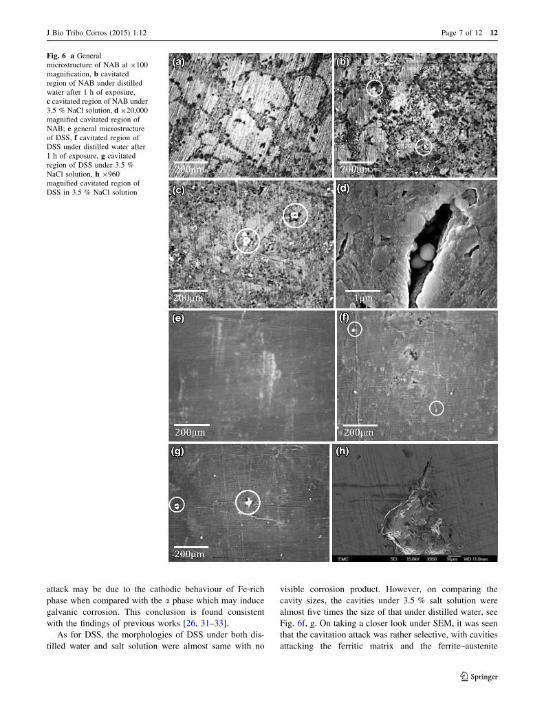
attack may be due to the cathodic behaviour of Fe-rich
phase when compared with the a phase which may induce
galvanic corrosion. This conclusion is found consistent
with the findings of previous works [26, 31–33].
As for DSS, the morphologies of DSS under both dis-
tilled water and salt solution were almost same with no
visible corrosion product. However, on comparing the
cavity sizes, the cavities under 3.5 % salt solution were
almost five times the size of that under distilled water, see
Fig. 6f, g. On taking a closer look under SEM, it was seen
that the cavitation attack was rather selective, with cavities
attacking the ferritic matrix and the ferrite–austenite
Fig. 6 a General
microstructure of NAB at 9100
magnification, b cavitated
region of NAB under distilled
water after 1 h of exposure,
c cavitated region of NAB under
3.5 % NaCl solution, d 920,000
magnified cavitated region of
NAB; e general microstructure
of DSS, f cavitated region of
DSS under distilled water after
1 h of exposure, g cavitated
region of DSS under 3.5 %
NaCl solution, h 9960
magnified cavitated region of
DSS in 3.5 % NaCl solution
J Bio Tribo Corros (2015) 1:12 Page 7 of 12 12
123

boundaries. Figure 6h shows a 40 9 70-lm-large cavity
formed in DSS under the salt solution where ductile failure
can be seen in the form of extrusion of the austenite at the
cavity boundary visible in Fig. 7. Also visible are tiny
microcracks and cleavage-like facets that may have been
caused by the austenite-to-martensite transformation either
due to high strain or due to the high temperature accredited
to cavitation. This result holds consistent with the findings
of the study by Al-Hashem and Riad [34].
3.2 Electrochemical Results
Figure 8 is the OCP curve obtained for DSS and NAB in
pure corrosion and erosion–corrosion in 3.5 % NaCl so-
lution. All the tests were conducted for 1 h. For the
cavitation erosion–corrosion tests, the cavitation rig was
switched on after 600 s to obtain the change in the
electrochemical behaviour of the sample materials. As can
be seen from the trend, there was a negative shift of OCP
from -70 to -500 mV. However, DSS was seen to attain
stability within 10 min at a lower voltage, and this OCP
shift can be attributed to the result of protective oxide layer
destroyed by cavitation erosion. Similarly, the trend for
NAB shifted to negative when the rig was turned on, but it
attained stability much quicker than DSS (within 100 s) at
a lower potential than that under pure corrosion. On
comparing the OCP trend of the two materials when un-
dergoing cavitation, it can be seen that while NAB reaches
stability at -210 mV at a lower voltage as compared to
DSS, the stability of DSS attained after the rig is switched
on is much lower than that of NAB showing that NAB has
higher corrosion resistance than DSS. Similar to the results
observed by Al-Hashem et al. [24], there was a shift in
corrosion potential for DSS under cavitation in the active
direction by 75 mV; however, there was not a very sub-
stantial shift in case of NAB. This may be due to the ex-
perimental reproducibility since several tests were
conducted giving similar results.
Figure 9 shows the electrochemical impedance spectra
(EIS) graph for the DSS and NAB samples with and
without cavitation. From the figure, it can be seen that both
the samples show very good resistance to corrosion both
with and without cavitation. Although it is clear that the
impedance was higher for DSS in saltwater alone without
cavitation as compared to DSS undergoing cavitation ero-
sion–corrosion, it was seen that the impedance of NAB
under corrosion was slightly lower than that under cavita-
tion erosion–corrosion. The reason for the high resistance
to corrosion may be explained from Fig. 10a, b, where it
can be seen that a high percentage of chromium was pre-
sent in the chemical composition of DSS, and also a highFig. 7 SEM images of plastic deformation at cavitation-damaged
edge for DSS in distilled water
Fig. 8 OCP for DSS and NAB in 3.5 % NaCl solution for 1 h with and without cavitation
12 Page 8 of 12 J Bio Tribo Corros (2015) 1:12
123
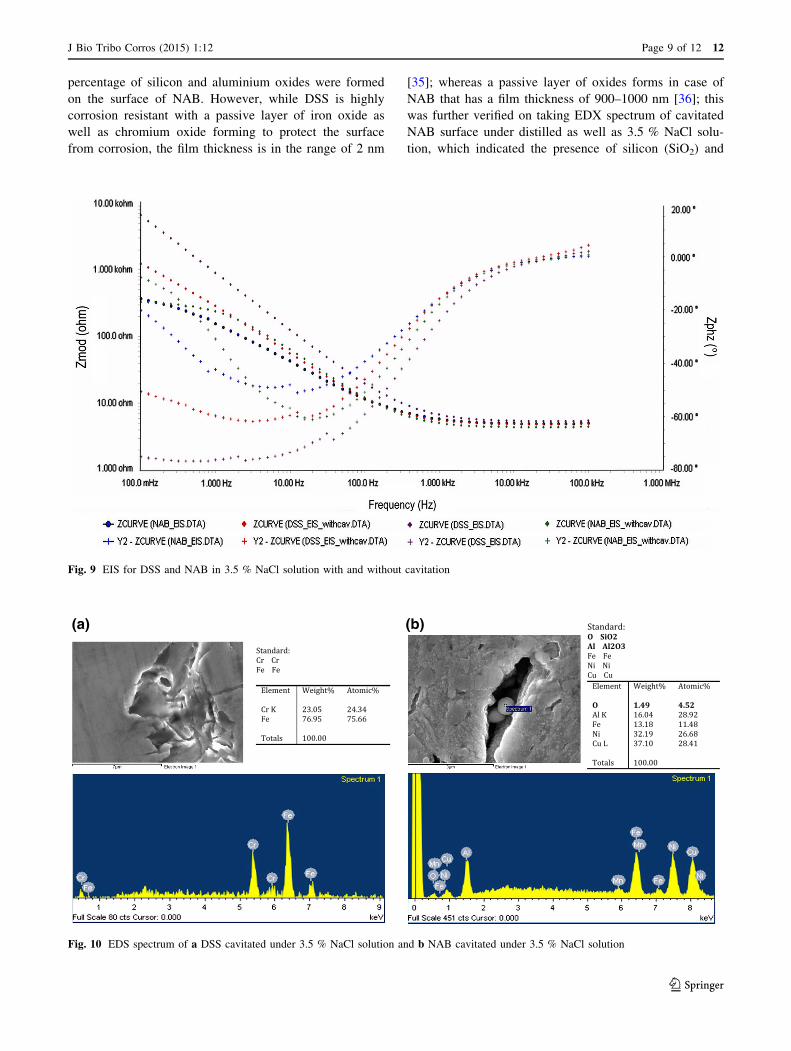
percentage of silicon and aluminium oxides were formed
on the surface of NAB. However, while DSS is highly
corrosion resistant with a passive layer of iron oxide as
well as chromium oxide forming to protect the surface
from corrosion, the film thickness is in the range of 2 nm
[35]; whereas a passive layer of oxides forms in case of
NAB that has a film thickness of 900–1000 nm [36]; this
was further verified on taking EDX spectrum of cavitated
NAB surface under distilled as well as 3.5 % NaCl solu-
tion, which indicated the presence of silicon (SiO2) and
Fig. 9 EIS for DSS and NAB in 3.5 % NaCl solution with and without cavitation
(a) (b)
Fig. 10 EDS spectrum of a DSS cavitated under 3.5 % NaCl solution and b NAB cavitated under 3.5 % NaCl solution
J Bio Tribo Corros (2015) 1:12 Page 9 of 12 12
123

aluminium oxides (Al2O3), see Fig. 10b. These may ac-
count for the high corrosion resistance of both the material
samples used.
3.3 Synergy Calculation
From Table 3, the value of volumetric mass loss for each
sample was extracted using the simple mass, volume and
density formula:
Density = mass/volume; ð3Þ
where density of NAB = 7.65 g/cm3 and density of
DSS = 7.8 g/cm3. Hence, the following values are
tabulated in Table 4 in order to compare the mass loss
obtained using precision weighing machine and Alicona.
The mass change observed during pure corrosion was mass
gain rather than mass loss, hence it is considered negative
since mass loss is considered positive.
From the pure corrosion measurements shown in
Table 4 and Eq. 3, the thickness of the passive layer
formed on the sample surface was calculated. The oxide
layers consisting predominant of Al203 in case of NAB and
Cr2O3 in case of DSS were found to be of thickness
0.24 lm and 0.03 lm, respectively.
Using Eqs. 1 and 2, and considering the values of
gravimetric mass loss from Table 4, the synergy can be
calculated and the values are tabulated in Table 5.
3.4 Discussion
It can be seen from Table 5 that for both NAB and DSS
synergy has measurable impact on their cavitation erosion–
corrosion. While the synergy between cavitation erosion
and corrosion for NAB was found to be 73.6 %, it is almost
half in case of DSS at 36.5 %, with DC (erosion-enhanced
corrosion) dominating the synergy result for both cases.
These values are in general much higher when compared
with the synergy results obtained by other studies. The
study by Neville, Hodgkiess and Dallas [37] found the
synergy for 2205 DSS eroded under liquid–solid jet
impingement under saline solution to be about 20 %,
whereas the vibratory cavitation as well as hydrodynamic
cavitation erosion–corrosion synergy tests conducted by
Wood and Hutton [38] showed S/T % values to be in the
range of 30% to[60 % for various materials tested under
3 % NaCl solution such as grey cast iron, 1020 mild steel,
304 SS and copper alloys. Several engineering alloys tested
in 3.5 % NaCl solution by Kwok et al. [39] showed very
low (negligible) S/T % of damage for corrosion-resistant
materials such as 316 SS, 304 SS and Zeron 100 super
DSS. However, it must be noted that these studies were
carried out with varying conditions, and also most of these
studies considered rate of depth of penetration as their
means of calculating synergy.
One reason for the existence of synergy could be due to
the difference in the quantity of dissolved gases present in
each medium. While 3.5 % NaCl solution may have higher
amount of dissolved oxygen, it also has dissolved minerals
and radicals among other such factors that can affect the
bubble nucleation, growth and impact. Distilled water is
considered to have negligible amount of dissolved miner-
als, and hence cavitation impact and results obtained in
distilled water can vary significantly from that in 3.5 %
NaCl solution. Also, few anomalies may exist due to cer-
tain assumptions made during the experiment such as, the
erosion test without any external electrochemical applica-
tion was considered as pure erosion test; however, there
was still a small level of corrosion taking place in the form
of passivity of the individual materials itself. This alone
may explain the difference in the mass change between the
two materials for pure erosion test when comparing
gravimetric with volumetric analyses. One way of immu-
nizing the material from any corrosion could be by using
the pH of the solution to move the material to immune
section of pourbaix diagram in order to protect it from
Table 4 Comparison between gravimetric mass loss and volumetric mass loss
Material used In distilled water cavitation erosion loss
(E)
In 3.5 % NaCl solution cavitation erosion–corrosion
loss (T)
Pure corrosion
mass gain
(C) (mg)Gravimetric
mass loss (in mg)
Volumetric mass
loss (in mg)
Gravimetric mass
loss (in mg)
Volumetric mass
loss (in mg)
Nickel aluminium bronze 1.00 0.88 1.48 1.29 -0.61
Duplex stainless steel 0.71 0.63 0.96 0.82 -0.10
Table 5 Synergism summary
for the samplesMaterial used T (mg) E (mg) C (mg) S = T-(E ? C) (mg) (S/T) 9 100 (%)
Nickel aluminium bronze 1.48 1.00 -0.61 1.09 73.6
Duplex stainless steel 0.96 0.71 -0.10 0.35 36.5
12 Page 10 of 12 J Bio Tribo Corros (2015) 1:12
123

corrosion. Also, instead of using distilled water, cathodic
protection can also be employed to prevent the samples
from corrosion; however, while cathodic protection can
prevent corrosion, it is difficult to suppress corrosion and
hydrogen evolution simultaneously as also explained by
Kwok et al. [39]. Hydrogen could cause embrittlement in
stainless steels, but it may also exert a cushioning effect,
reducing mechanical erosion, and this may potentially in-
crease the relative contribution of synergism.
For the synergy result, gravimetric mass loss values were
considered due to the reason that, although both gravimetric
as well as volumetric mass loss measurements are useful
and efficient in their own account, they both have major
shortcomings. While the data obtained using precision
weighing machine can be considered accurate, several
factors may affect the results, such as sediments of eroded
titanium probe tip deposited on the sample, dissolved NaCl
salt deposits and absorption of water by porous layers/coats
if any, as well as other impurities that cannot be detected
and fully prevented. Also, as the samples are introduced to a
corrosive environment, if they are highly corrosive and
form corrosion product immediately after erosion, it is hard
to tell how much mass is actually lost accurately. The mass
balance does not take into account these factors, and this
could cause deviation in the final result. On the other hand,
volumetric analyses using Alicona can be equally crude
since the highest magnification achievable using Alicona is
1009, which may sometimes cause loss of data while
looking at very smooth and reflective surface, or due to re-
entrant topography of the surface. Also, in case that there
are sediments, corrosion products, micro scratches and
burrs existing on the sample surface, Alicona cannot dif-
ferentiate and do selective volume loss, which again causes
deviation from the result. It may also manifest its own
roughness and waviness of the surface when using lower
magnification or highly reflective surface, which was ap-
plicable for the experiments undertaken. Due to this,
gravimetric analyses were slightly more preferable.
4 Conclusion
From the experiments conducted, it can be concluded that
after a short period of exposure to cavitation both NAB and
DSS have measurably high synergistic effect under
cavitation erosion–corrosion. In the case of NAB, the
synergy between cavitation wear and corrosion was found
to be 73.6 % and for DSS it was found to be 36.5 %. The
data obtained from electrochemical measurement for the
cavitation erosion–corrosion test showed that, although
duplex SS exhibited higher resistance to corrosion under
seawater alone, NAB exhibited much higher resistance to
corrosion when subjected to cavitation. Also, NAB attained
stability much faster and at higher potential than DSS,
proving that it is more corrosion resistant.
The NAB surface was seen to undergo selective cavitation
erosion–corrosion attack at the a phase and the a-j phase
boundaries with ductile deformation around the cavity, while
the j precipitates and precipitate-free a zones were found to
suffer no visible cavitation after 1 h of cavitation test in both
distilled water as well as 3.5 % NaCl. The DSS was seen to
undergo ductile failure in the cavitated zone in the form of
extrusion of the austenite at the cavitation pit along with mi-
crocracks and cleavage facets that could be attributed to the
austenite-to-martensite transformation by either the high
strain rate or high temperatures generated during cavitation.
And because of that the erosion process was found to be
predominantly of plastic nature with little of no fatigue failure
noticed at this stage, due to this NAB was found to be more
susceptible to erosion under both the conditions as compared
to duplex SS with prominent selective cavitation erosion of
alpha phase in the microstructure since DSS is harder than
NAB. From the experiments conducted, it was concluded that
synergy had measurable impact on the cavitation erosion–
corrosion of both NAB and duplex SS, and the overall synergy
for NAB was found to be higher than that for DSS.
Conflict of interest None.
References
1. Vyas B, Hansson ILH (1990) The cavitation erosion-corrosion of
stainless steel. Corros Sci 30(8): 761–770
2. Engelberg G, Yahalom J, Kalir E (1985) Observations on the
cavitation of steels. Corros Sci 25(10) 871–882
3. Tomlinson WJ, Talks MG (1991) Erosion and corrosion of cast
iron under cavitation conditions. Tribol Int 24:67
4. Wood RJK, Fry SA (1989) The synergistic effect of cavitation
erosion and corrosion for copper and Cupro-Nickel in seawater.
J Fluids Eng 111(3):271
5. Kwok C, Man H, Cheng F(1998) Cavitation erosion and damage
mechanisms of alloys with duplex structures. Mater Sci Eng A
242(1–2):108–120
6. Kwok CT, Man HC, Cheng FT (1998) Cavitation erosion of
duplex and super duplex stainless steels. Scr Mater 39(9):
1229–1236
7. Zheng Y, Luo S, Ke W (2007) Effect of passivity on electro-
chemical corrosion behavior of alloys during cavitation in
aqueous solutions. Wear 262(11–12):1308–1314
8. Kwok CT, Man HC, Leung LK (1997) Effect of temperature, pH
and sulphide on the cavitation erosion behaviour of super duplex
stainless steel. Wear 211(1):84–93
9. Luo SZ, Zheng YG, Li MC, Yao ZM, Ke W (2003) Effect of
cavitation on corrosion behavior of 20SiMn low-alloy steel in 3%
sodium chloride solution. Corrosion 59(7):597–605
10. Kwok C, Cheng F, Man H (2000) Synergistic effect of cavitation
erosion and corrosion of various engineering alloys in 3.5% NaCl
solution. Mater Sci Eng A http://linkinghub.elsevier.com/retrieve/
pii/S0921509300008996
J Bio Tribo Corros (2015) 1:12 Page 11 of 12 12
123

11. Yu H, Zheng YG, Yao ZM (2006) The cavitation erosion and
erosion-corrosion behavior of carbon steel in simulating solutions
of three rivers of China. Mater Corros 57(9):705–714
12. Sakamoto A, Funaki H, Matsumura M (2000) Seminar influence
of galvanic macro-cell corrosion on the cavitation erosion dura-
bility. Int cavitation Eros test Semin
13. Thiruvengadam A, Waring SJ (1966) Mechanical properties of
metals and their cavitation damage resistance. J Ship Res 10:1–9
14. Kwok C, Man H, Cheng F (2001) Cavitation erosion–corrosion
behaviour of laser surface alloyed AISI 1050 mild steel using
NiCrSiB. Mater Sci Eng A 303(1–2):250–261
15. Kwok CT, Cheng FT, Man HC Cavitation erosion and corrosion
behaviors of laser-aluminized mild steel. Surf Coat Technol
200(11):3544–3552
16. Man HC, Kwok CT, Yue TM (2000) Cavitation erosion and
corrosion behaviour of laser surface alloyed MMC of SiC and
Si3N4 on Al alloy AA6061. Surf Coat Technol 132(1):11–20
17. Kwok C, Man H, Cheng F (2000) Cavitation erosion and pitting
corrosion behaviour of laser surface-melted martensitic stainless
steel UNS S42000. Surf Coat Technol 126(2–3):238–255
18. Kwok CT, Man HC, Cheng FT (1998) Cavitation erosion and
pitting corrosion of laser surface melted stainless steels. Surf Coat
Technol 99(3):295–304
19. Shifler DA (2005) Understanding material interactions in marine
environments to promote extended structural life. Corros Sci
47(10):2335–2352
20. Stack MM, Jana BD (2004) Modelling particulate erosion–cor-
rosion in aqueous slurries: some views on the construction of
erosion–corrosion maps for a range of pure metals. Wear
256(9–10):986–1004
21. Stack MM, Corlett N, Zhou S (1997) A methodology for the
construction of the erosion-corrosion map in aqueous environ-
ments. Wear 203:474–488
22. Wood RJK (2006) Erosion–corrosion interactions and their effect
on marine and offshore materials. Wear 261(9):1012–1023
23. Richman RH, Mcnaughton WP (1990) Correlation of cavitation
properties of metals erosion behavior with mechanical. Wear
140:63–82
24. Al-Hashem A, Caceres PG,Abdullah A, Shalaby HM (1997)
Cavitation corrosion of duplex stainless steel in Seawater. Cor-
rosion 53(2):103–113
25. Al-Hashem A, Caceres PG, Riad WT, Shalaby HM (1995)
Cavitation corrosion behavior of cast nickel-aluminum bronze in
seawater. Corrosion 51(5):331–342
26. Al-Hashem A, Riad W (2002) The role of microstructure of
nickel–aluminium–bronze alloy on its cavitation corrosion be-
havior in natural seawater. Mater Charact 48(1):37–41
27. Duplex stainless steel IMOA (2013). http://www.imoa.info/moly_
uses/moly_grade_stainless_steels/duplex_stainless_steel.php.
Accessed 28 Aug 2013
28. Culpan EA, Rose G (1978) Microstructural characterization of
cast nickel aluminium bronze. J Mater Sci 13(8):1647–1657
29. Hasan F, Iqbal J, Ridley N (1985) Microstructure of as-cast alu-
minium bronze containing iron. Mater Sci Technol 1(4):312–315
30. Faires KB (2003) Characterization of microstructure and micro-
texture in longitudinal sections from friction stir processed
nickel-aluminum bronze. North Carolina State University
31. Takaloo AV, Daroonparvar MR, Atabaki MM, Mokhtar K (2011)
Corrosion behavior of heat treated nickel-aluminum bronze alloy
in artificial seawater. Mater Sci Appl 02(11):1542–1555
32. Lorimer GW, Hasan F, Iqbal J, Ridley N (1986) Observation of
microstructure and corrosion behaviour of some aluminium
bronzes. Br Corros J 21(4):244–248
33. Culpan EA, Rose G (1979) Corrosion behaviour of cast nickel
aluminium bronze in sea water. Br Corros J 14(3):160–166
34. Al-Hashem A, Riad W (2002) The effect of duplex stainless steel
microstructure on its cavitation morphology in seawater. Mater
Charact 47(2001):389–395
35. Fredriksson W (2012) Depth Profilling of the Passive Layer on
Stainless Steel using Photoelectron Spectroscopy. Uppsala
Universitet
36. Daroonparvar A, Atabaki MR, Mazar, Vakilipour M (2011) Ef-
fect of pre-heat treatment on corrosion behaviour of nickel-alu-
minium bronze alloy. Assoc Metall Eng Serbia 17(4):183–198
37. Neville A, Hodgkiess T, Dallas JT (1995) A study of the erosion-
corrosion behaviour of engineering steels for marine pumping
applications. Wear 186:497–507
38. Wood RJK, Hutton SP (1990) The synergistic effect of erosion
and corrosion: published results
39. Kwok C, Cheng F, Man H (2000) Synergistic effect of cavitation
erosion and corrosion of various engineering alloys in 3.5% NaCl
solution. Mater Sci Eng A 290(1):145–154
12 Page 12 of 12 J Bio Tribo Corros (2015) 1:12
123
Related Documents