The Study of Long-term Energy-saving LED Airfield Lighting System Yang Jianhong 1 ,Li Lei 2 ,Li Tuo 3 ,Li Xingbo 4 The Second Research Institute of CAAC, 17 South Section 2 ,2nd Ring Road, Chengdu City, Sichuan Province, China 17 South Section 2,2nd Ring Road, Chengdu City, Sichuan Province, China [email protected], [email protected],[email protected], [email protected] Keywords: LED, lighting system, power supply system, sine wave regulator, energy saving Abstract. Based on the analysis of power consumption of the circuits, isolation transformers and secondary cables of traditional lighting systems, this paper proposes a long-term power efficient lighting system regarding LED airfield lamps, without modifying the topology of power circuit. New types of sine wave regulator and lamp controller are designed accordingly for this lighting system. Introduction Traditional airfield lighting systems are powered up by constant current regulators in which the output terminal of boosting transformer connects the main circuit cable, and connects multiple isolation transformers in lighting circuit. The secondary side of isolation transformers connects airfield lamps, halogen lamp or tungsten bromine lamp. Figure 1 shows the topology. Figure 1. Topology of Traditional Airfield Lighting Systems In the power supply circuit of traditional airfield lighting, the consumption of electrical energy is mainly composed of four parts: consumption of power of light source, the loss of main circuit cables, isolation transformers and secondary cable of lamps. Take the circuit composed by 100 taxiway sidelights (tungsten bromine lamp) as an example. The following is the analysis of consumption of airfield lighting system. For the convenience of estimation, the length of main circuit cable is Lmain =10km, the length of secondary cable Lsec =5000m, and each lamp uses 50W of isolation transformer for power supply. The consumption of each part of circuit is estimated as below. 1) Power of Light Source The power of a single taxiway sidelight with traditional halogen light source is P0 =50W, and the power consumed by circuit lamp is Plamp=N* P0 =50*100=5000W. (1) 2) Loss of Main Circuit Cable When the temperature is 20℃, the impedance of commonly used 6KV and 10KV airfield lighting exclusive cables with the sectional area of 6mm 2 is R0 =2.917Ω/km。If the regulator output current is i = 6.6A, the loss of main circuit cable is P main =I 2 * R0 *Lmain =6.6*6.6*2.917*10=1271W. (2) Constant Current Regulator Isolation Transformer Isolation Transformer Isolation Transformer International Forum on Energy, Environment Science and Materials (IFEESM 2017) Copyright © 2018, the Authors. Published by Atlantis Press. This is an open access article under the CC BY-NC license (http://creativecommons.org/licenses/by-nc/4.0/). Advances in Engineering Research, volume 120 983

Welcome message from author
This document is posted to help you gain knowledge. Please leave a comment to let me know what you think about it! Share it to your friends and learn new things together.
Transcript
The Study of Long-term Energy-saving LED Airfield Lighting System
Yang Jianhong1 ,Li Lei2 ,Li Tuo3 ,Li Xingbo4 The Second Research Institute of CAAC, 17 South Section 2 ,2nd Ring Road, Chengdu City,
Sichuan Province, China
17 South Section 2,2nd Ring Road, Chengdu City, Sichuan Province, China [email protected], [email protected],[email protected], [email protected]
Keywords: LED, lighting system, power supply system, sine wave regulator, energy saving Abstract. Based on the analysis of power consumption of the circuits, isolation transformers and secondary cables of traditional lighting systems, this paper proposes a long-term power efficient lighting system regarding LED airfield lamps, without modifying the topology of power circuit. New types of sine wave regulator and lamp controller are designed accordingly for this lighting system.
Introduction
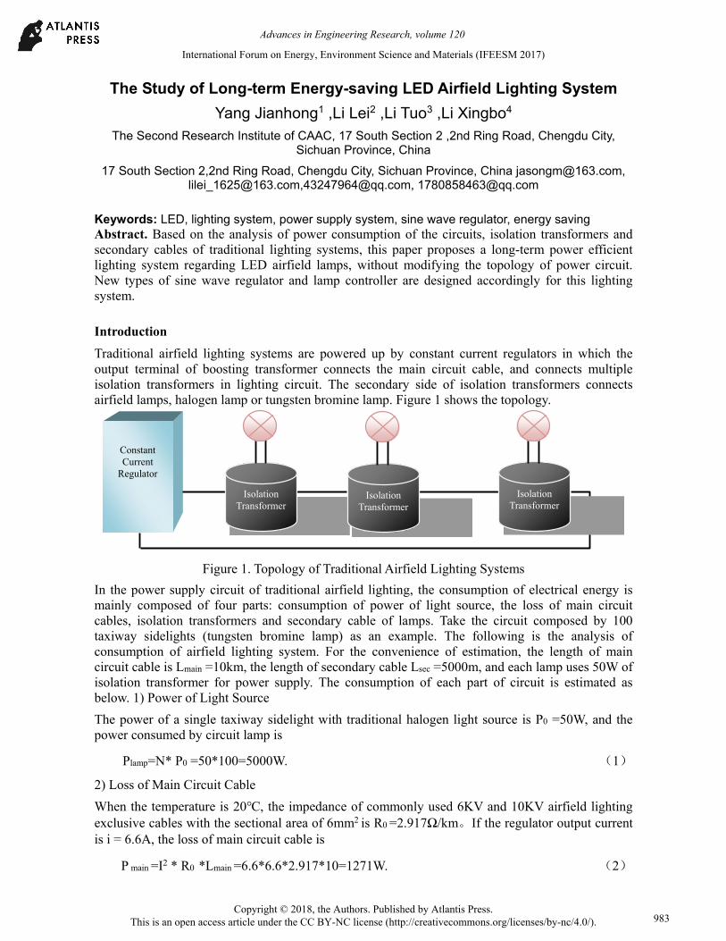
Traditional airfield lighting systems are powered up by constant current regulators in which the output terminal of boosting transformer connects the main circuit cable, and connects multiple isolation transformers in lighting circuit. The secondary side of isolation transformers connects airfield lamps, halogen lamp or tungsten bromine lamp. Figure 1 shows the topology.
Figure 1. Topology of Traditional Airfield Lighting Systems
In the power supply circuit of traditional airfield lighting, the consumption of electrical energy is mainly composed of four parts: consumption of power of light source, the loss of main circuit cables, isolation transformers and secondary cable of lamps. Take the circuit composed by 100 taxiway sidelights (tungsten bromine lamp) as an example. The following is the analysis of consumption of airfield lighting system. For the convenience of estimation, the length of main circuit cable is Lmain =10km, the length of secondary cable Lsec =5000m, and each lamp uses 50W of isolation transformer for power supply. The consumption of each part of circuit is estimated as below. 1) Power of Light Source
The power of a single taxiway sidelight with traditional halogen light source is P0 =50W, and the power consumed by circuit lamp is
Plamp=N* P0 =50*100=5000W. (1)
2) Loss of Main Circuit Cable
When the temperature is 20, the impedance of commonly used 6KV and 10KV airfield lighting exclusive cables with the sectional area of 6mm2 is R0 =2.917Ω/km。If the regulator output current is i = 6.6A, the loss of main circuit cable is
P main =I2 * R0 *Lmain =6.6*6.6*2.917*10=1271W. (2)
Constant Current
Regulator
Isolation Transformer
Isolation Transformer
Isolation Transformer
International Forum on Energy, Environment Science and Materials (IFEESM 2017)
Copyright © 2018, the Authors. Published by Atlantis Press. This is an open access article under the CC BY-NC license (http://creativecommons.org/licenses/by-nc/4.0/).
Advances in Engineering Research, volume 120
983
3) Loss of Isolation Transformers
The loss of isolation transformers depends on its efficiency and load power. The commonly-used transformers in airports are 30W, 50W, 100W and 200W transformers. Considering the aging factor, the efficiency of 50W isolation transformers is estimated as η50 =0.75. Thus the loss of 100 50W isolation transformers is
Ptran =N* P0 *(1-η50)=100*50* (1-0.75) =1250W. (3)
4) Loss of Lamp Secondary Cables
If the unit loss of 2.5 mm2 lamp secondary cables is P’=0.305W/m in 6.6A current, the loss of secondary cable is
Psec=Lsec* P’ =5000*0.305=1525W (4)
In short, it can be concluded, from (2), (3) and (4), that the circuit loss of a traditional circuit powered by 50W isolation transformer and composed of 100 taxiway sidelight is
Pcircuit= P main + Ptran + Psec =1271 +1250 +1525 =4046W (5)
In formula (1), the consumption of circuit light source is Plamp =5000W, indicating severe circuit power consumption which amounts to 80.92% of the power consumption of circuit lamp.
At present, LED airfield lamps have replaced traditional airfield lamps in some domestic airports in China, but power efficiency is not satisfying. Xi’an Xianyang Airport has replaced partial runway edge lights and taxiway central line lights with LED airfield lamps of ADB, and the 50w halogen lamp of taxiway edge lights is replaced by 1w LED lamp beads, but its energy conservation percentage is less than 40%.
The main reason is that, using LED airfield lamp on traditional circuit greatly decreases the power consumption of lamps, but the power loss of the circuit does not decrease accordingly. For the entire airfield lighting system, the system power consumption reduces at best a half, which is far from adequate to demonstrate the energy saving effect. Therefore, setting up a long-term energy saving LED airfield lighting system will help airports to achieve the goal of energy conservation.
Power Supply System Based on LED Airfield Lighting System
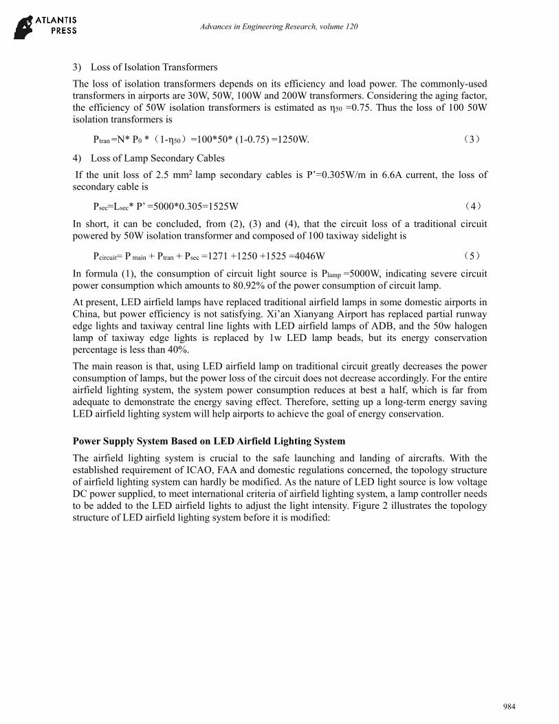
The airfield lighting system is crucial to the safe launching and landing of aircrafts. With the established requirement of ICAO, FAA and domestic regulations concerned, the topology structure of airfield lighting system can hardly be modified. As the nature of LED light source is low voltage DC power supplied, to meet international criteria of airfield lighting system, a lamp controller needs to be added to the LED airfield lights to adjust the light intensity. Figure 2 illustrates the topology structure of LED airfield lighting system before it is modified:
Advances in Engineering Research, volume 120
984
Figure 2. Topology of LED Airfield Lighting System
The luminous efficiency of LED is much higher than that of tungsten bromine lamps and halogen lamps. The luminous efficiency of white light LED amounts to as high as 150 lumens/w, while the luminous efficiency of colour LED reaches 80 lumens/w. Through theoretical calculation, software modelling as well as lamp verification, it proves that LED airfield lights do not need to be driven by the current of 6.6A. Even for the 20000CD approach light, the 2A current is sufficient for the criteria. For the taxiway edge light with the minimum intensity requirement, driving a 1w blue LED only needs a current of 300mA.
The regulator (CCR) of airfield lighting system is in fact an AC constant current power supply whose output current, output frequency and phase are key parameters. Considering the level of difficulty and accuracy of parameter detection, the output frequency is more suitable to be used as the parameter of light intensity levels. Thus, a new type of LED airfield lighting power system can be designed as follows: with different intensity requirements, when the regulator outputs different constant current, it at the same time outputs sine wave of different frequencies between 1Hz and 2Hz. When the different frequencies are detected, the LED airfield lights adjust the driving current to ensure the output is equivalent to corresponding intensity. 1Hz frequency interval is adopted, and the maximum circuit current is 2A. The relationship of intensity levels and regulator output of the new type of airfield lighting power system is shown in Table 1.
Table 1. Intensity Levels Specified by New Power System of Airfield Lighting
intensity level output frequency output currency
level 1 48 0.5A
level 2 49 0.5A
level 3 50 0.5A
level 4 51 1A
level 5 52 2A
The new power system of airfield lighting system is able to guarantee that while assuring the light intensity requirement at each level of intensity, the circuit loss is less than the loss powered by the 2.8A~6.6A, without adding extra transmission links for intensity level information, facilitating the modification of traditional airfield lighting systems. Take the circuit of 100 taxiway edge lamps as
Advances in Engineering Research, volume 120
985
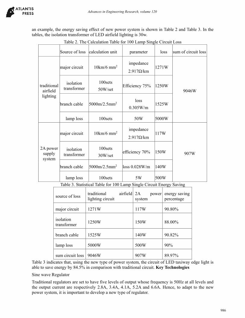
an example, the energy saving effect of new power system is shown in Table 2 and Table 3. In the tables, the isolation transformer of LED airfield lighting is 30w.
Table 2. The Calculation Table for 100 Lamp Single Circuit Loss
Source of loss calculation unit parameter loss sum of circuit loss
traditional airfield lighting
major circuit 10km/6 mm2 impedance
2.917Ω/km 1271W
9046W
isolation transformer
100sets
50W/set Efficiency 75% 1250W
branch cable 5000m/2.5mm2 loss
0.305W/m 1525W
lamp loss 100sets 50W 5000W
2A power supply system
major circuit 10km/6 mm2 impedance
2.917Ω/km 117W
907W isolation
transformer 100sets
30W/set efficiency 70% 150W
branch cable 5000m/2.5mm2 loss 0.028W/m 140W
lamp loss 100sets 5W 500W
Table 3. Statistical Table for 100 Lamp Single Circuit Energy Saving
source of loss traditional airfield lighting circuit
2A power system
energy saving percentage
major circuit 1271W 117W 90.80%
isolation transformer
1250W 150W 88.00%
branch cable 1525W 140W 90.82%
lamp loss 5000W 500W 90%
sum circuit loss 9046W 907W 89.97%
Table 3 indicates that, using the new type of power system, the circuit of LED taxiway edge light is able to save energy by 84.5% in comparison with traditional circuit. Key Technologies
Sine wave Regulator
Traditional regulators are set to have five levels of output whose frequency is 50Hz at all levels and the output current are respectively 2.8A, 3.4A, 4.1A, 5.2A and 6.6A. Hence, to adapt to the new power system, it is important to develop a new type of regulator.
Advances in Engineering Research, volume 120
986
Differing from traditional regulators, apart from maintaining the constant output feature of traditional regulators, the new regulators also possess the function of frequency-converted output. The basic principle is to convert 220v AC via AC→DC→AC, and to generate clean sine wave current with adjustable output frequency and amplitude within a certain range. By regulating the output sine wave frequencies, the regulators send intensity level order to control the intensity levels of LED lights and, in the meanwhile, modify output current to fit in with the current, improving power factor demanded by corresponding intensity level, eliminating unnecessary power consumption and saving energy.
The regulator employs the most advanced IGBT inverter output technology in the world, which uses the high performance precision power supply controlled by advanced micro processors. It has the functionalities of over-current protection, short-circuit protection, over-voltage protection, under-voltage protection and overload protection, as well as fault alarm display, ensuring the safety of the regulator. It is featured by strong load adaptability, good output waveform and user interface. Small and light, it is easy to operate.
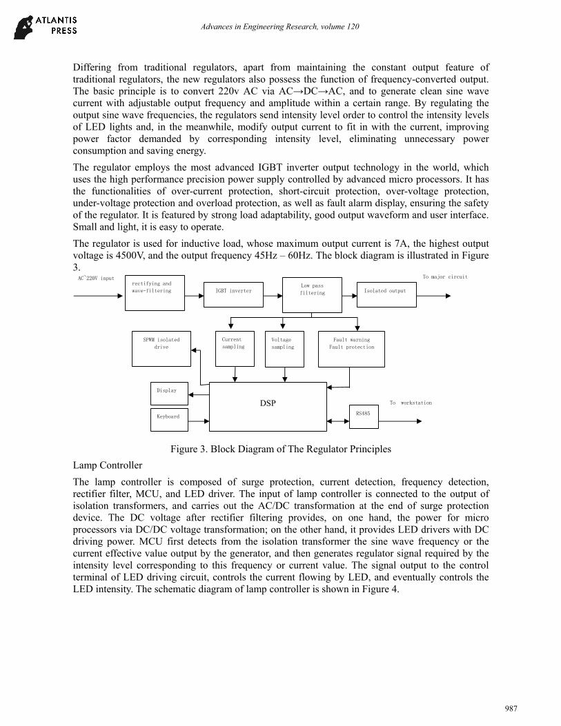
The regulator is used for inductive load, whose maximum output current is 7A, the highest output voltage is 4500V, and the output frequency 45Hz – 60Hz. The block diagram is illustrated in Figure 3.
Figure 3. Block Diagram of The Regulator Principles
Lamp Controller
The lamp controller is composed of surge protection, current detection, frequency detection, rectifier filter, MCU, and LED driver. The input of lamp controller is connected to the output of isolation transformers, and carries out the AC/DC transformation at the end of surge protection device. The DC voltage after rectifier filtering provides, on one hand, the power for micro processors via DC/DC voltage transformation; on the other hand, it provides LED drivers with DC driving power. MCU first detects from the isolation transformer the sine wave frequency or the current effective value output by the generator, and then generates regulator signal required by the intensity level corresponding to this frequency or current value. The signal output to the control terminal of LED driving circuit, controls the current flowing by LED, and eventually controls the LED intensity. The schematic diagram of lamp controller is shown in Figure 4.
rectifying and wave-filtering
IGBT inverterLow pass
filtering Isolated output
SPWM isolated drive
Current
samplingVoltage
sampling
Fault warning
Fault protection
DSP
Display
Keyboard RS485
AC~220V input To major circuit
To workstation
Advances in Engineering Research, volume 120
987
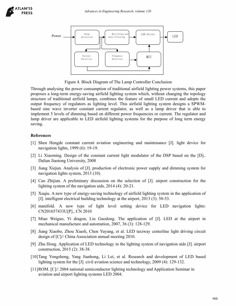
Figure 4. Block Diagram of The Lamp Controller Conclusion
Through analysing the power consumption of traditional airfield lighting power systems, this paper proposes a long-term energy-saving airfield lighting system which, without changing the topology structure of traditional airfield lamps, combines the feature of small LED current and adopts the output frequency of regulators as lighting level. This airfield lighting system designs a SPWM-based sine wave inverter constant current regulator, as well as a lamp driver that is able to implement 5 levels of dimming based on different power frequencies or current. The regulator and lamp driver are applicable to LED airfield lighting systems for the purpose of long term energy saving.
References
[1] Shen Hengde constant current aviation engineering and maintenance [J]. light device for navigation lights, 1999 (6): 19-19.
[2] Li Xiaoming. Design of the constant current light modulator of the DSP based on the [D].. Dalian Jiaotong University, 2008
[3] Jiang Xiejun. Analysis of [J]. production of electronic power supply and dimming system for navigation lights system, 2013 (10).
[4] Cao Zhijian. A preliminary discussion on the selection of [J]. airport construction for the lighting system of the navigation aids, 2014 (4): 20-21.
[5] Xuqiu. A new type of energy-saving technology of airfield lighting system in the application of [J]. intelligent electrical building technology at the airport, 2013 (3): 50-53.
[6] manifold. A new type of light level setting device for LED navigation lights: CN201657433U[P]., CN 2010
[7] Miao Weiguo, Yi dragon, Liu Guodong. The application of [J]. LED at the airport in mechanical manufacture and automation, 2007, 36 (3): 128-129.
[8] Jiang Xiaobo, Zhou Xiaoli, Chen Yuyang, et al. LED taxiway centerline light driving circuit design of [C]// China Association annual meeting 2010.
[9] Zhu Hong. Application of LED technology in the lighting system of navigation aids [J]. airport construction, 2015 (2): 38-38.
[10] Tang Yongsheng, Yang Jianhong, Li Lei, et al. Research and development of LED based lighting system for the [J]. civil aviation science and technology, 2009 (4): 129-132.
[11] ROM. [C]// 2004 national semiconductor lighting technology and Application Seminar in aviation and airport lighting systems LED 2004.
LED Surge
protection Rectifying and
wave-filteringLED driver
Current detection
Frequency
detectionMCU
Power
Advances in Engineering Research, volume 120
988
Related Documents