Th 1 e Sliding Wear of UHMWPE against Ceramics in Solutions Containing Proteins By Melissa Kernick A thesis submitted to the faculty of engineering, University of Cape Town in fulfillment of the degree of Master of Science in Engineering Department of Materials Engineering University of Cape Town August 1996 r : .. :,:· .. 1: r\:) ,r t.:1 :·c< ::::·:=::·1·.·_,:;_;·' • . ·.··,,·\ .. •.• ;:·1: 1.. •)r hi 1'1;< L , '--' • __ : .. ·' : : :-: .:'::. -- . -· ..c;. .••: ...• :."- •.• ·. ,.)

Welcome message from author
This document is posted to help you gain knowledge. Please leave a comment to let me know what you think about it! Share it to your friends and learn new things together.
Transcript
Th1e Sliding Wear of UHMWPE against Ceramics in Solutions
Containing Proteins
By
Melissa Kernick
A thesis submitted to the faculty of engineering, University of Cape Town
in fulfillment of the degree of Master of Science in Engineering
Department of Materials Engineering
University of Cape Town
August 1996
r .,.~;~~:-~,· : .. :,:· .. :::·::,:~~--~::·~~'.:;,,;:·~~·::··;.::;:·::?·::~"·;~~~~~ ~. 1: ::~i r\:) ,r t.:1 :·c< ='·~ ::::·:=::·1·.·_,:;_;·' •. ·.··,,·\ .. :-.~ •.• :.·,.:~,~ :.:,;_·.~::.i,_n "-)~~:~ ;:·1:
1.. •)r hi 1'1;< L ,
'--' • __ : .. ·' : : :-: .:'::. -- . -· _,,~. ..c;. .•• : ...• :."- •.• ·. ,.)
The copyright of this thesis vests in the author. No quotation from it or information derived from it is to be published without full acknowledgement of the source. The thesis is to be used for private study or non-commercial research purposes only.
Published by the University of Cape Town (UCT) in terms of the non-exclusive license granted to UCT by the author.
Abstract
The sliding wear behaviour of ultrahigh molecular weight polyethylene (UHMWPE)
sliding against partially stabilised zirconia (PSZ) and alumina ceramic counterfaces in
various lubricating media was investigated. Wear tests were conducted in order to
investigate the effect that the addition of proteins to the lubricating solutions had on the
wear behaviour of the UHMWPE against a smooth counterface of PSZ . The lubricants
selected were physiological saline solution, distilled water and physiological saline
' solution containing small additions of synovial fluid and up to 15% by volume of
albumen solution. The effect of the addition of proteins to the lubricating solutions on
the production of wear debris was also studied.
ii
The effect of changing the counterface roughness from Ra of 0.01 µm to 0.06µm was also
investigated. The wear behaviour ofUHMWPE against alumina ceramics in distilled
water was compared to that of UHMWPE against PSZ in similar conditions.
The results showed that the addition of protein to the lubricating solution reduced the
wear rates over sliding distances of 35km after which wear rates resembled those found
from distilled water. The polymer pins tested in distilled water lost material form the
surface in the form of sheets that were readily lost once shear had taken place. The
polymer pins tested in the protein solutions lost material in the form of stringers from the
pin surfaces. At increased sliding distances, cracking of the polymer, wear pin surfaces
was also observed for the pins tested in distilled water, cracking was more widespread for
increased protein contents in the lubricating solutions.
The mode of polymer removal from the wear pins is through de bonding at the interface of
the deformed surface layers and the bulk material. The mode of material removal for
UHMWPE in distilled water is one of macroscopic asperity wear whereby the polymer
asperity peaks are significantly larger than those on the wearing counterface. Plastic
strain is built up in the polymer peaks during sliding wear and polymer are removed when
the plastic failure strain of the polymer peak is reached. These de bonded regions are lost
in the form of sheet debris. In the protein containing solutions the debonded regions
iii
appeared as stringers. After long exposure times in albumen containing solutions deep
cracking of the polymer wear pin surface was observed. Polymer removal from the wear
pins tested in the protein containing lubricants was concluded to be a result of the
weakening of the intermolecular forces between the oriented long chain molecules on the
surface which are then sheared from the pin surface in the form of stringers.
Transfer of UHMWPE to the PSZ surfaces occurred in an uneven manner and no
coherent transfer layer was observed. Analysis of the ceramic counterfaces which had
been tested in the protein solutions revealed the presence of a film of protein on the
surface of the ceramic counterface.
The size and morphology of the polymer debris was found to be dependent on the
composition of the lubricating solutions. The debris characteristic of the albumen
containing solutions was found to be smaller and spherical in shape when compared with
that typical of the distilled water solution which was generally larger and flake like in
morphology. The morphology of the debris retrieved from the tests conducted in distilled
water suggests that this debris was produced by polymer shearing from the interface of
the deformed zone and the bulk material. The morphology of the finer particles is
indicative of having been formed from rolled up stringers or the break up of larger wear ·
particles or from the loss of transferred particles on the counterface.
Increasing the counterface roughness was found to increase the wear rates in all solutions
by about 3.4 times. More polymer transfer was observed on the ceramic counterfaces
with transferred polymer acting as preferential sites for further transfer. No coherent
transfer layer was observed. It was concluded that increasing the counterface roughness
results in more polymer particles being trapped by asperities on the rougher counterfaces.
The wear rates of the UHMWPE sliding against PSZ were lower than those found for the
UHMWPE sliding against alumina counterfaces. This was attributed to the better surface
finish of the PSZ counterfaces and the lack of porosity of the PSZ counterfaces when
compared with the alumina counterfaces.
iv
It was concluded that the addition of proteins to the lubricating solutions does have an
effect on the wear rates. Furthermore the addition of proteins to the lubricating solutions
influences the dominant wear mode and the way in which debris is formed, in addition to
having an effect on the size and morphology of the debris that is formed as a result of the
wear process.
v
Acknowledgements
My most heartfelt thanks goes to the following people. Professor Allen for his unfailing
patience especially with my last minute decisions. To Glen Newins, Nick Dreeze and
Reggie Hendricks for their technical help and to Bernard Greeves and James Peterson for
their extremely prompt photographic work. Thanks also to Drs. Grobblar, Scher, Pollack
and Hanna for their help in the supply of synovial fluid. And to Wynand Louw for XPS,
SIMS and AES analyses. And to Candy, Suzie and Mom for helping me through the
rough spots, I can't thank you enough.
Thank you to Boart Longyear Research Centre and Eskom for financial assistance that
made this project possible.
Abstract
Introduction
Aims of Research Project
Contents
Chapter 1 - Structure and Properties of UHMWPE
1.1 Polymer Structure
II
1
2
3
I . I . I Introduction 3
I. I .2 Crystallites 3
I. I .3 The Unit Cell 4
1.2 Polymer Morphology in the Melt Crystallised State 4
1.3 Molecular Orientation 7
1.4 The Amorphous Region lO
1.5 Mechanical Properties 11
1.6 Electrical Properties 13
Chapter 2 - Friction and Wear 14
2.1 Friction 14
2.1.1 Introduction I4
2.1.2 True Area of Contact I 5
2.1.3 Adhesion Theory of Friction I 7
2.1.4 Elastic Plastic Transition 19
2. I .5 Junction Growth 20
2. I .6 Sliding Friction of Plastics 20
2.2 Wear 22
2.2.1 Introduction 22
2.2.2 Adhesive Wear 23
2.2.3 Abrasive Wear 24
2.2.4 Fatigue Wear 25
VI
2.2.5 Corrosive Wear
2.3 Polymer Properties Affecting Friction and Wear
2.3.l Introduction
2.3.2 Viscoelasticity
2.3.3 Mechanical Properties
2.4 Wear of UHMWPE
2.4.1 Introduction
2.4.2 Wear Modes
2.4.3 Counterface Roughness
2.4.4 Grinding Direction
2.4.5 Morphology
2.5 Wear in Prosthetic Implants
2.5.l Introduction
2.5.2 Materials in Use
2.5.3 UHMWPE Wear in Implants
2.5.4 Wear Debris Effects
2.6 Lubrication
2.6.1 Introduction
2.6.2 Hydrodynamic Lubrication
2.6.3 Elastohydrodynamic Lubrication
2.6.4 Thin Film or Mixed Lubrication
2.6.5 Boundary Lubrication
2.7 Lubrication of Implants
2. 7.1 Introduction
2.7.2 Articular Cartilage
2.7.3 Synovial Fluid
2.7.4 Lubrication Action of Joints
2.7.5 The Effect of Protein on the Lubricating Function of
Synovial Fluid
vii
26
27
27
27
28
29
29
29
30
31
32
33
33
35
37
38
40
40
40
41
42
42
44
44
45
45
47
~; .-_
Vlll
Chapter 3 - Experimental Methods 49
3.1 Test Materials 49
3.2Test Apparatus 52
3.2.l Specimen Location 55
3.2.2 Loading Mechanism 55
3.2.3 Coolant Bath 55
3.3 Test Parameters 56
3.4 Experimental Measurements 60
3.4.1 Measurement of Specific Wear Rate 60
3 .4.2 Measurement of Counterface Roughness 60
3.4.3 Measurement of Frictional Forces 60
3.4.4 Collection of Wear Debris 62
3.4.5 TestReproducibility 63
3.5 Polymer Characterisation 64 :i I 3.5.l Scanning Electron Microscopy 64
3.5.2 Energy Dispersive Spectroscopy (EDS) 64
3.5.3 OpticalMicroscopy 64
3.5.4 Scratch Tests 65
3.6 Counterface Characterisation 66
3.6.1 Optical Microscopy 66
3 .6.2 Scanning Electron Microscopy 66
3.6.3 X"."Ray Photoelectron Microscopy (XPS) 66
3.6.4 Secondary Ion Mass Spectroscopy 66
3 .6.5 Auger Electron Spectroscopy 66
3.7 Wear Debris Analysis · 68
3. 7 .1 Scanning Electron Microscopy (SEM) 68
3.7.2 Energy Dispersive Spectroscopy (EDS) 68
Chapter 4 - Results 69
4.1 Introduction 69
ix
4.2 Wear 70
4.2.1 Wear Studies on Zirconia Counterfaces with Average
Initial Surface Roughness O.Olµm 74
4.2.2 Wear Studies for Increasing Counterface Roughness 80
4.2.3 Wear Studies on Two Ceramic Counterfaces 82
4.2.4 Summary 83
4.3 Friction 84
4.4 Polymer Behaviour 85
4.4.1 SEM Examination of Worn Polymer Pin Surfaces 85
Part 1 Distilled Water Lubrication 87
Part 2 5% Synovial Fluid Lubricant 88
Part 3 5% Albumen Lubricant 89
Part 4 10% Albumen Lubricant 90
Part 5 15% Albumen Lubricant 91
Part 6 Distilled Water Lubricant against Rough
(0.06µm) PSZ Counterface Surfaces 93
Part 7 Alumina Counterfaces 95
4.4.2 Scratch Tests of UHMWPE Surfaces 96
4.4. 3 Investigation of Subsurface Deformation of
UHMWPE by Polarised Light 97
4.5 Nature of the Wear Scar 99
4.5.1 Optical Examination of Wear Scar 99
4.5.2 SEM Examination of Counterface Wear Tracks 103
4.5.3 Analysis of Wear Scar 108
Section I XPS Analysis of Wear Scar 108
Section II SIMS Analysis of Wear Scar 111
Section III AES Analysis of Wear Scar 112
4.6 Nature of the Wear Debris 114
4.6.1 Morphology of Wear Debris 114
x
4.6.2 Morphology Analysis 118
4.6.3 Size Distribution Analysis ofUHMWPE Wear Debris
in Albumen Solutions 121
Chapter 5 - Discussion 127
5.1 Introduction 127
5.2 Friction and Wear Behaviour of UHMWPE 128
5.2.1 Saline Lubricated Sliding Wear 128
5.2.2 Water Lubricated Sliding Wear 128
5.2.2.1 The Effect of Changing the Counterface
Roughness on Wear Rates 130
5.2.2.2 The Effect of Changing the Counterface
on the Coefficient of Friction 131
5.2.3 Protein Lubricated Sliding Wear 132
5.2.3.1 Transfer Layer Formation 132
5.2.3.2 UHMWPE Behaviour 134
5.2.3.3 The Effect of Changing the Counterface
Roughness 13 6
5.3 Production of Wear Debris 138
Chapter 6 Conclusions 141
Appendices 143
Appendix A Other Materials Used for Implants 143
A. l Particle Filled Materials 143
A.2 Fibre Reinforced Materials 143
A.3 Ceramic Fibre Reinforced Ceramics 145
A.4 Hydroxyapatite-reinforced Polyethylene 146
A.6 Carbon Composite Ceramics 14 7
A. 7 Boroaluminosilicate Ceramics 14 7
A.8 Silica, Aluminium Nitride and Aluminium Oxide 147
Appendix B Amino Acids 148
Appendix C Polysaccharides
Appendix D Glycoproteins
Appendix E Properties of UHMWPE (Chirulen)
References
151
152
153
155
xi
INTRODUCTION
In recent years, ultrahigh molecular weight polyethylene (UHMWPE) has been
established as one of the foremost engineering polymers in sliding wear applications
The excellent mechanical, physical and chemical properties of this material coupled
with its biocompatibility has ensured widespread use. Applications range from seals
and bushings in water powered mining equipment to prosthetic hip and knee implants.
The majority of research into behaviour and mechanisms of the sliding wear of
UHMWPE has been conducted against metallic surfaces, mainly stainless alloys.
However, the increasing use of engineering ceramic materials such as alumina and
partially stabilised zirconia (PSZ), particularly in prosthetics, has necessitated further
sliding wear studies using these materials.
Whilst it has been shown that the establishment of a coherent UHMWPE transfer
layer on the counterface is necessary to ensure low wear rates, any loss of UHMWPE
as debris has important consequences in bioengineering. UHMWPE debris is one of
the most common causes of failure in total hip replacements (THR'S)[l-12].
Particles ofUHMWPE wear debris are transported to the hard and soft tissue adjacent
to the prosthesis where they activate inflammatory cells or macrophages. The
activated macrophages stimulate osteoclasts to form local bone resorption around the
implant [13]. This results in osteolysis or bone loss and ultimately leads to the failure
of the implant [2-12]. These tissue reactions are dependent on the size and
morphology of the wear debris. However relatively little research has been conducted
into the size distribution of the UHMWPE wear debris formed during sliding wear
and the conditions which control its production. This work is an attempt to address
this issue.
2
The Aims of this Research Project
The objective of this work was to study the tribological behaviour of UHMWPE
during reciprocating sliding wear against ceramic materials under fluid lubricating
conditions, and to ascertain the conditions which control the production and size of
UHMWPE debris.
The specific aims of this project were:
(i) to investigate the sliding weir behaviour ofUHMWPE against PSZ and alumina
ceramic counterfaces in various lubricating conditions which simulate those found
in the human body
(ii) to determine the effect of the various lubricants on the formation of transfer films
and the size and shape of the wear debris generated.
(iii) to qualitatively determine the size distribution of the wear debris generated for a
given test.
(iv)to investigate the influence of counterface roughness (RJ, on the wear behaviour
of UHMWPE when sliding against ceramic counterfaces.
CHAPTER!
LITERATURE REVIEW
STRUCTURE AND PROPERTIES OF UHMWPE
1.1 Polymer Structure
1.1.1 Introduction
Polyethylene is an aliphatic hydrocarbon of the type -CHrCHrCHz-. It is a
thermoplastic and is semicrystalline. Properties such as strength, stiffness, impact
strength, solubility and hardness are affected by the degree of crystallinity of the
polyethylene [14].
The molecular structure of polyethylene must be considered during any investigation
into its wear behaviour and the formation of wear debris.
1.1.2 Crystallites
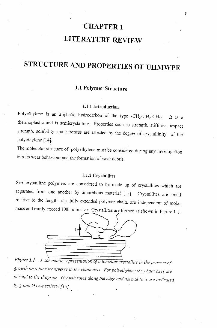
Semicrystalline polymers are considered to be made up of crystallites which are
separated from one another by amorphous material [15]. Crystallites are small
relative to the length of a fully extended polymer chain, are independent of molar
mass and rarely exceed I OOnm in size. Crystallites are formed as shown in Figure 1.1.
Figure 1.1 A schematic representation o a lame/far crystallite in the process of
grovvth on a face transverse to the chain axis. For polyethylene the chain axes are
normal to the diagram. Grmvth rates along the edge and normal to it are indicated
by g and G respectively [I 6}.
3
4
A point is reached where the chain growing into a crystallite becomes strained as the
rest of the molecule becomes tightly entangled. Incorporating more segments of the
chain at this stage \vould require work to be done against stress. This \Vork soon
equals the decrease in free energy \vhich would result from further crystallisation.
This effectively impedes further crystallisation. Separated sections of the same chain
may become involved in the simultaneous development of two different crystallites.
Thus each crystallite is surrounded by an amorphous band of polymer [15.16].
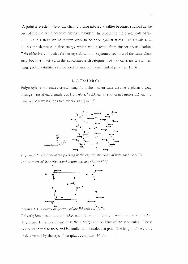
1.1.3 The Unit Cell
Polyethylene molecules crystallising from the molten state assume a planar zigzag
arrangement along a single bonded carbon backbone as sho\vn in Figures 1.2 and 1.3
This is the lowest Gibbs free e:1ergy state [ 14.1 7].
::i....1;;; .. ,:"/
',.:--/, ~-,~is x,.;.:
I ,1
Figure 1.2 A model ofrhe packing in the CJysra! srrucrure ofpolyerh_vleni: rPEJ
Dimensions of the orthorhombic unit cell are shown [1-} V
I \
• ::.,.:___• ________ ___,..--.
---.r __.' 'l •
bi I
;•H 1 \
i IC
• •
• • ' :.,1...,:--:-e __ H ________ -,.---.
a -~ . Figure 1.3 Ac-axis projecrion of the PE unit ct!!! [1-j
Polyethylene has an orthorhombic unit cell as described by lattice \ ectors a. b and c.
The a and b \ectors characterise the side-by-side packing of the molecules. The c
\ ector is normal to these and is parallel to the molecubr p:<is. The length ~f the c-a:<is
is determined by the crystallographic repeat unit [ 14, 1 7l
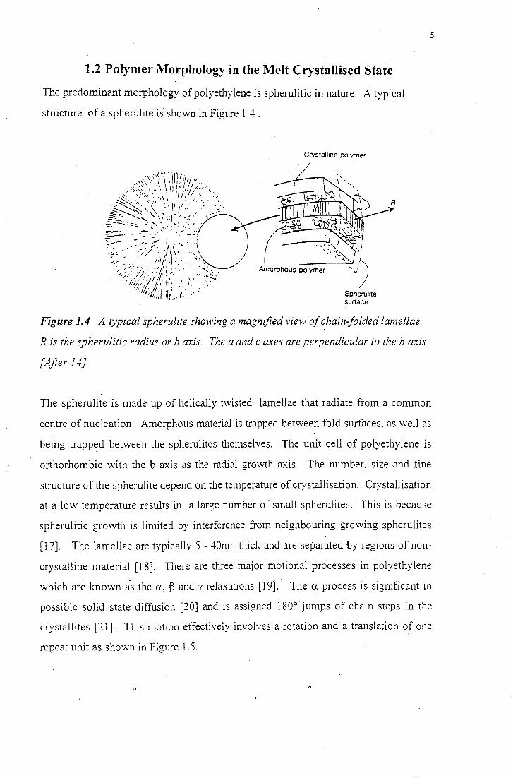
1.2 Polymer Morphology in the Melt Crystallised State
The predominant morphology of polyethylene is spherulitic in nature. A typical
structure of a spherulite is shown in Figure 1.4 .
Crystalline polymer
Spherulite surface
5
~· '' Figure 1.4 A typical spherulite showing a magnified view of chain-folded lamellae.
~: R is the spherulitic radius orb axis. The a and c axes are perpendicular to the b axis f
[After 14}.
The spherulite is made up of helically twisted lamellae that radiate from a common
centre of nucleation. Amorphous material is trapped between fold surfaces, as well as
being trapped between the spherulites themselves. The unit cell of polyethylene is
orthorhombic with the b axis as the radial growih axis. The number, size and fine
structure of the spherulite depend on the temperature of crystallisation. Crystallisation
at a low temperature results in a large number of small spherulites. This is because
spherulitic growth is limited by interference from neighbouring growing spherulites
[ 1 7]. The lamellae are typically 5 - 40nm thick and are separated by regions of non
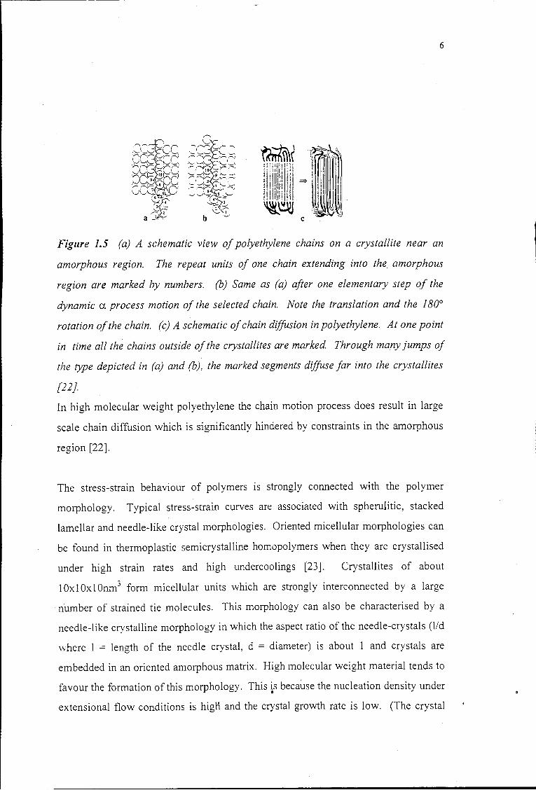
crystalline material [18]. There are three major motional processes in polyethylene
which are known as the a, ~ and y relaxations [19]. The a process is significant in
possible solid state diffusion [20] and is assigned 180° jumps of chain steps in the
crystallites [21]. This motion effectively involves a rotation and a translation of one
repeat unit as shown in Figure 1.5.
6
Figure 1.5 (a) A schematic view of polyethylene chains on a crystallite near an
amorphous region. The repeat units of one chain extending into the amorphous
region are marked by numbers. (b) Sarne as (a) after one elementary step of the
dynamic a process motion of the selected chain. Note the translation and the 180°
rotation of the chain. (c) A schematic of chain diffusion in polyethylene. At one point
in time all the chains outside of the crystallites are marked. Through many jumps of
the type depicted in (a) and (b), the marked segments diffuse far into the crystallites
[22}.
In high molecular weight polyethylene the chain motion process does result in large
scale chain diffusion which is significantly hindered by constraints in the amorphous
region [22].
The stress-strain behaviour of polymers is strongly connected with the polymer
morphology. Typical stress-strain curves are associated with spherulitic, stacked
lamellar and needle-like crystal morphologies. Oriented micellular morphologies can
be found in thermoplastic semicrystalline homopolymers when they are crystallised
under high strain rates and high undercoolings [23]. Crystallites of about
1Ox1Ox1 Onm3 form micellular units which are strongly interconnected by a large
number of strained tie molecules. This morphology can also be characterised by a
needle-like crystalline morphology in which the aspect ratio of the needle-crystals (lid
\vhere l = length of the needle crystal, d = diameter) is about 1 and crystals are
embedded in an oriented amorphous matrix. High molecular weight material tends to
favour the formation of this morphology. This is because the nucleation density under
extensional flow conditions is higli and the crystal growth rate is low. (The crystal
7
growth rate is low as a result of the high entanglement density of the molecules when
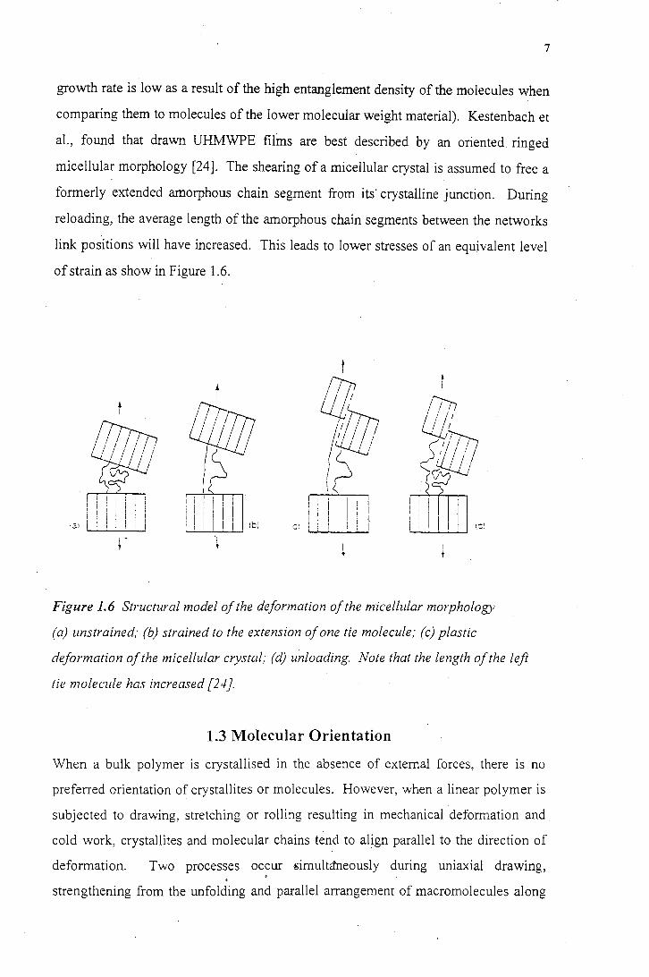
comparing them to molecules of the lower molecular weight material). Kestenbach et
al., found that drawn UHMWPE films are best described by an oriented ringed
micellular morphology [24]. The shearing of a micellular crystal is assumed to free a
formerly extended amorphous chain segment from its· crystalline junction. During
reloading, the average length of the amorphous chain segments between the networks
link positions will have increased. This leads to lower stresses of an equivalent level
of strain as show in Figure 1.6.
Ill •
t I
flt
' !l/)JJJ (f!lJ ~!flt \ I I
,. .. /·' I 1q I ~ 1r ' i ' I I I I I I ! I I
i I l I 11
' ! I !
l ! ! I i · l I I I , I . : i I I I I !bi . I !Cl ·21 I · , . 1 I c:
r
Figure 1.6 Structural model of the deformation of the micellular morphology
(a) unstrained; (b) strained to the extension of one tie molecule; (c) plastic
deformation of the micellular crystal; (d) unloading Note that the length of the left
tie molecule has increased [24).
1.3 Molecular Orientation
When a bulk polymer is crystallised in the absence of external forces, there is no
preferred orientation of crystallites or molecules. However, when a linear polymer is
subjected to drawing, stretching or rolling resulting in mechanical deformation and
cold work, crystallites and molecular chains tend to align parallel to the direction of
deformation. Two processes occur simultctneously during uniaxial drawing, . . strengthening from the unfolding and parallel arrangement of macromolecules along
8
the draw axis and fracture caused by the rupture of stressed ties chains and the
splitting of crystallites [25]. Bulk crystallised polymers with a spherulitic structure
which is composed of lamellar crystals growing from central nuclei, are changed upon
drawing into a fibre structure. Suehiro et al. [26], postulated that, if an unfolded
extended chain is released from the restraining force associated with molecular
potential, it will refold to form a crystallite, the size of which is determined by the
draw temperature. This results in a fibre structure which is made up of a sequential
arrangement of crysta!Iites which are interconnected by tie molecules. Any
mechanically unfolded extended chains will be buried by the folded crystallites.
Pigeon et al. [27] have shown that, during the roll-drawing processes, the extended
chains in the crystalline phase are almost completely oriented at a draw ratio of 7 and
that the trans C-C bonds in the amorphous phase orient more readily in the draw
direction than the gauche effects. Peterlin suggested that the following structural
metamorphosis occurs during deformation: A multilayer lamellar crystal is destroyed
with chain tilting, slipping and breaking off of blocks of folded chains, with
subsequent re-formation of folded chains in the fibre [28]. The molecules in the
structure of semicrystalline polymers are stretched and aligned during deformation at
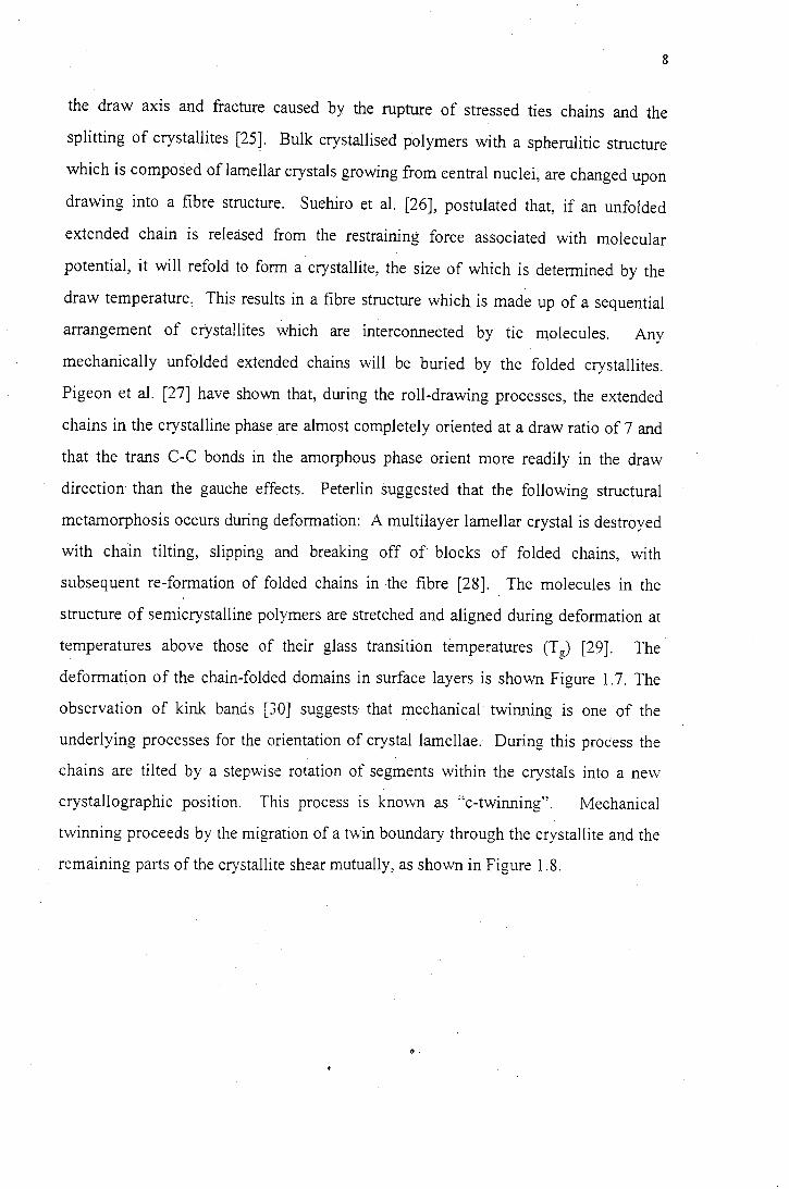
temperatures above those of their glass transition temperatures (T11) [29]. The "'
deformation of the chain-folded domains in surface layers is shown Figure 1.7. The
observation of kink bands [30] suggests that mechanical twinning is one of the
underlying processes for the orientation of crystal lamellae. During this process the
chains are tilted by a stepwise rotation of segments within the crystals into a new
crystallographic position. This process is known as "c-twinning". Mechanical
twinning proceeds by the migration of a twin boundary through the crystallite and the
remaining parts of the crystallite shear mutually, as shown in Figure 1.8.
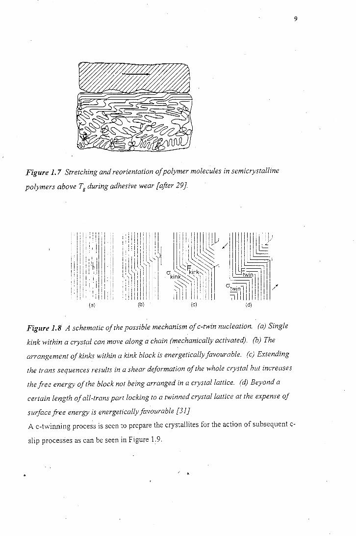
Figure 1. 7 Stretching and reorientation of polymer molecules in semicrystalline
polymers above Tg during adhesive wear [after 29}.
(a)
Figure 1.8 A schematic of the possible mechanism of c-twin nucleation. (a) Single
kink within a crystal can move along a chain (mechanically activated). (b) The
arrangement of kinks within a kink block is energetically favourable. (c) Extending
the trans sequences results in a shear deformation of the whole crystal but increases
the free energy of the block not being arranged in a crystal lattice. (d) Beyond a
certain length of all-trans part locking to a twinned crystal lattice at the expense of
surface free energy is energetically favourable [31}
9
A c-twinning process is seen to prepare the crystallites for the action of subsequent c-
slip processes as can be seen in Figure 1. 9.
/ .
! .11'1·1111
1·1r
1rll/l 1
1
-cr ! i ~ i ! I ' I ! ! I ! !
---.,..,...,-,.~- -- -- --- -- - --- --- -- -i :1 ! i j : 1 I
(a)
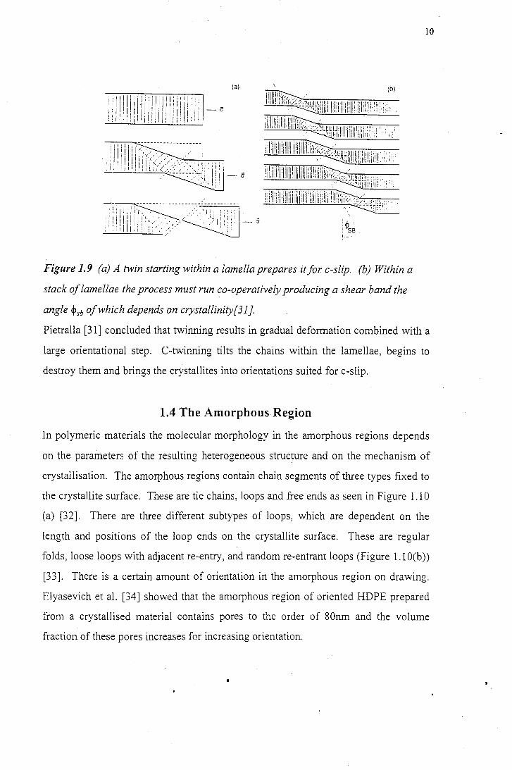
Figure 1.9 (a) A twin starting within a lamella prepares it for c-slip. (b) Within a
stack of lamellae the process must run co-operatively producing a shear band the
angle ~sb of which depends on crystallinity[31}.
IO
Pietralla [31] concluded that twinning results in gradual deformation combined with a
large orientational step. C-twinning tilts the chains within the lamellae, begins to
destroy them and brings the crystallites into orientations suited for c-slip.
1.4 The Amorphous Region
In polymeric materials the molecular morphology in the amorphous regions depends
on the parameters of the resulting heterogeneous structure and on the mechanism of
crystallisation. The amorphous regions contain chain segments of three types fixed to
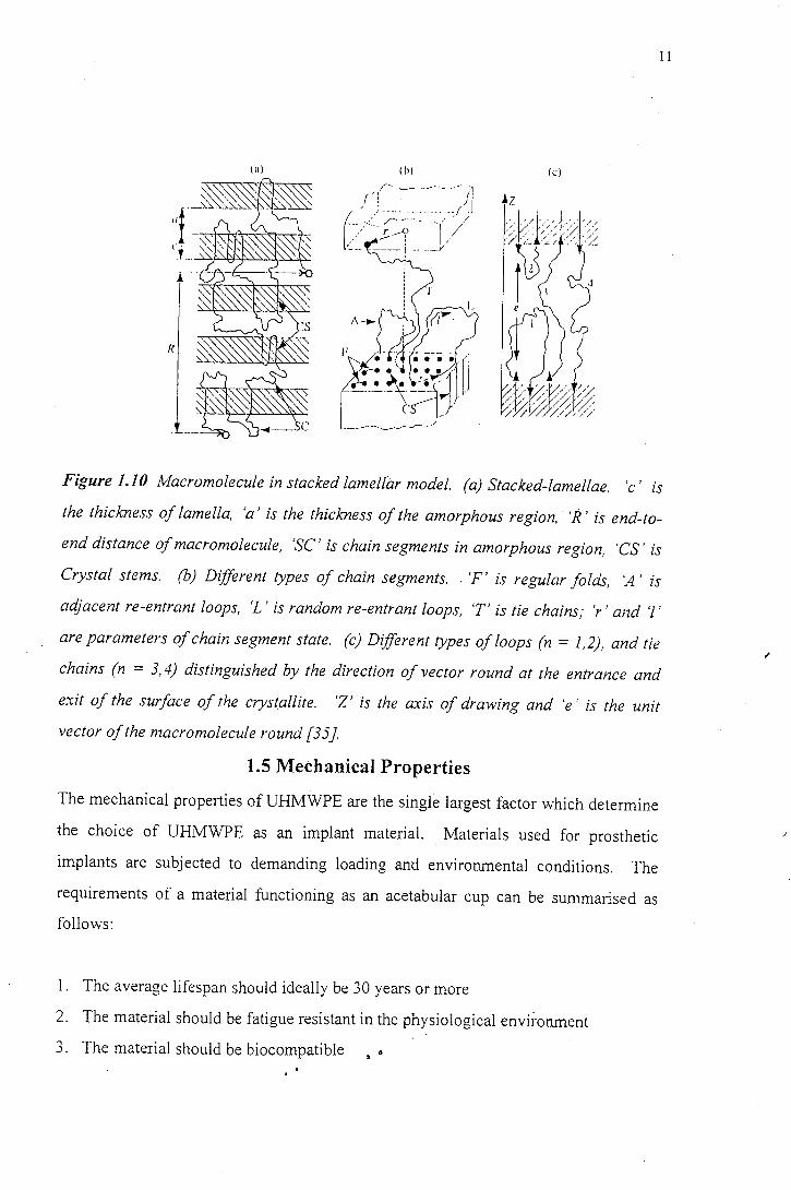
the crystallite surface. These are tie chains, loops and free ends as seen in Figure 1.10
(a) (32]. There are three different subtypes of loops, which are dependent on the
length and positions of the loop ends on the crystallite surface. These are regular
folds, loose loops with adjacent re-entry, and random re-entrant loops (Figure 1.1 O(b))
(33]. There is a certain amount of orientation in the amorphous region on drawing.
Elyasevich et al. (34] showed that the amorphous region of oriented HDPE prepared
from a crystallised material contains pores to the order of 80nm and the volume
fraction of these pores increases for increasing orientation.
11
(a) (h) (c)
Figure 1.10 Macromolecule in stacked lamellar model. (a) Stacked-lamellae. 'c' is
the thickness of lamella, 'a' is the thickness of the amorphous region, 'R' is end-to
end distance of macromolecule, 'SC' is chain segments in amorphous region, 'CS' is
Crystal stems. (b) Different types of chain segments. . 'F' is regular folds, 'A' is
adjacent re-entrant loops, 'L' is random re-entrant loops, 'T' is tie chains,· 'r ·and 'l'
are parameters of chain segment state. (c) Different types of loops (n = 1,2), and tie
chains (n = 3, 4) distinguished by the direction of vector round at the entrance and
exit of the surface of the crystallite. 'Z' is the axis of drawing and 'e' is the unit
vector of the macromolecule round {35].
1.5 Mechanical Properties
The mechanical properties of UHMWPE are the single largest factor which determine
the choice of UHMWPE as an implant material. Materials used for prosthetic
implants are subjected to demanding loading and environmental conditions. The
requirements of a material functioning as an acetabular cup can be summarised as
follows:
1. The average lifespan should ideally be 30 years or more
2. The material should be fatigue resistant in the physiological environment
3. The material should be biocompatible &
I
.I
12
4. The material should be able to withstand loading without substantial dimensional
changes and no brittle failure
5. There should be minimal creep
6. There should be minimal stress corrosion
7. The material should maintain its properties in the physiological environment, i.e.
it should be stable at 3 7°C and should not react to the presence of synovial fluid or
. blood plasma
The mechanical properties of polyethylene are particularly dependent on the
molecular weight and the degree of branching of the polymer. Other factors
influencing the observed mechanical properties of polyethylene are: the rate of testing,
the temperature of the test, the method of specimen preparation and the size and shape
of the specimen. These must therefore be kept constant for results. of any tests to be
comparable [36].
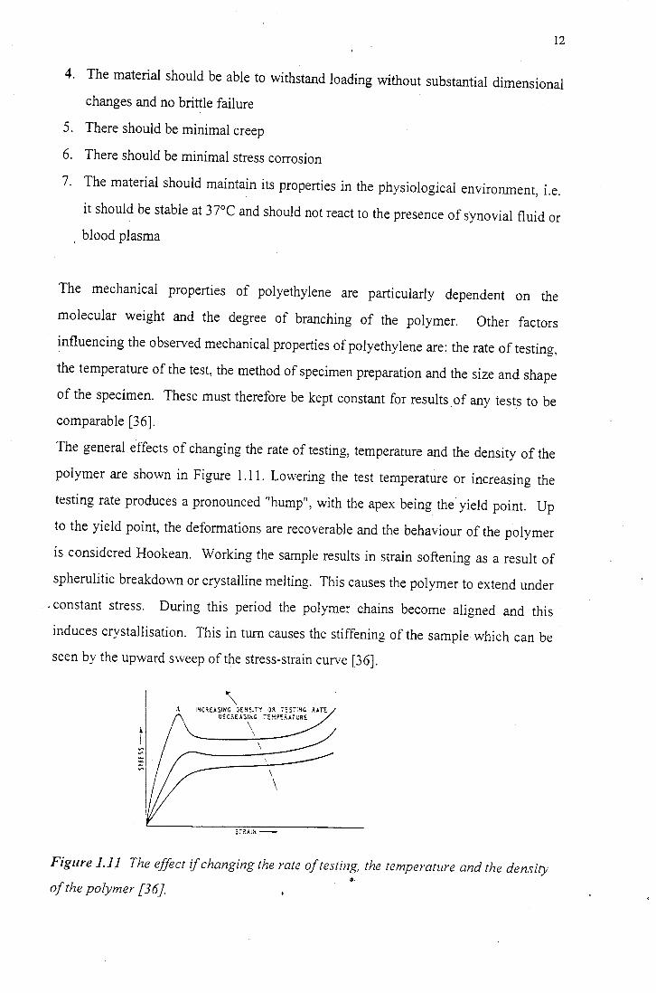
The general effects of changing the rate of testing, temperature and the density of the
polymer are shown in Figure 1.11. Lowering the test temperature or increasing the
testing rate produces a pronounced "hump", with the apex being the yield point. Up
to the yield point, the deformations are recoverable and the behaviour of the polymer
is considered Hookean. Working the sample results in strain softening as a result of
spherulitic breakdown or crystalline melting. This causes the polymer to extend under
. constant stress. During this period the polymer chains become aligned and this
induces crystallisation. This in turn causes the stiffening of the sample which can be
seen by the upward S\Veep of the stress-strain curve [36].
\ A IHC~E.ISIHG JE~SITT OR 7!ST:HC ?.ATE
OEC?.EASIHG TE~PE?.ATWRE
\ \
\ \
5i~A!H -
Figure 1.11 The effect if changing the rate of testing, the temperature and the density •· of the polymer.f36].
13
Elongation to break is dependent on the density of the material. High density
polymers tend to be more brittle than those of lower molecular weight. Polyethylene \
will deform continuously under load (i.e. it will creep). The mechanical properties of
UHMWPE define the way in which the UHMWPE reacts to a wear situation and these
will be dealt with in greater detail in section 2.4.
1.6 Electrical Properties
Polyethylene (PE) has good insulating properties when compared to other dielectric •.
materials. It is non-polar, and therefore its power factor and dielectric constant are
almost independent of temperature and frequency. The dielectric constant is linearly
dependent on density. The oxidation of PE with the formation of carbonyl groups can
cause a large increase in the power factor and therefore antioxidants are added to
reduce this effect [36]. It is important to consider the electrical properties of an
implant materials because they are subject to an ionic environment. Furthermore, the
presence of proteins in the physiological environment can be complicated by the
electrical properties of a polymer substrate because, the way in which proteins adsorb
onto a polymer surface is largely determined by the polarity and the charge on the
polymer surface [3 7].
CHAPTER2
LITERATURE REVIEW
FRICTION AND WEAR
2.1 Friction
2.1.1 Introduction
14
When a polymer slides over a rigid substrate, the force of friction between the two
materials is a result of the action of two mechanisms; an adhesion mechanism and· a
deformation mechanism [38]. The adhesion mechanism arises from the interaction of
the intermolecular forces across the interface, which necessitates work being done to
break these forces so that sliding can occur. The deformation mechanism arises from
the mechanical interaction of the two surfaces. The deformation component is the
contribution to the total frictional force from the ploughing of asperities of the harder
solid through the surface of the softer polymer. Surface melting, material transfer,
reorientation and chemical degradation can contribute to the adhesion component of
friction, while viscoelastic plougliing and elastic tearing can contribute to the
deformation component of friction [3 9].
15
2.1.2 True Area of Contact
Real surfaces are not atomically smooth, so when two surfaces come into contact, the
asperities on the respective surfaces and the deformation properties of the materials
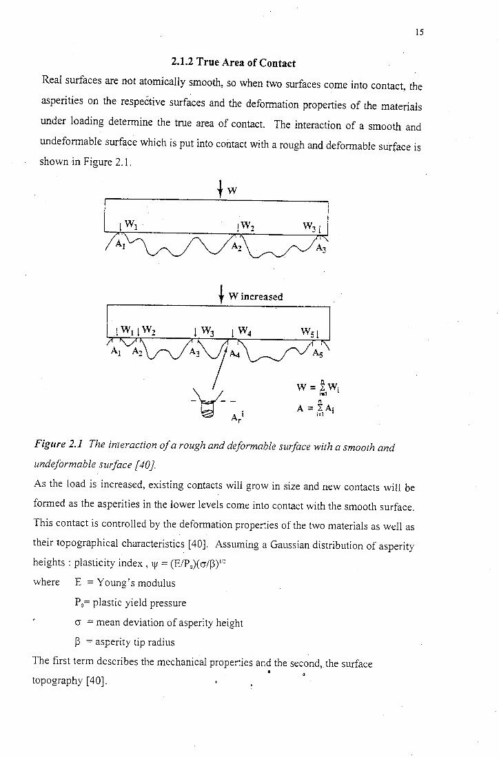
under loading determine the true area of contact. The interaction of a smooth and
undeformable surface which is put into contact with a rough and deformable surface is
shown in Figure 2.1.
t Wincreased
W=~W-i•1 I
n
A= ;~1Ai
Figure 2.1 The interaction of a rough and deformable surface with a smooth and
undeformable surface [40}.
As the load is increased, existing contacts will grow in size and new contacts will be
formed as the asperities in the lower levels come into contact with the smooth surface.
This contact is controlled by the deformation properties of the two materials as well as
their topographical characteristics [ 40]. Assuming a Gaussian distribution of asperity
heights : plasticity index, \Jf = (E/P0)(cr/~) 1 "2
where E =Young's modulus
P0= plastic yield pressure
cr = mean deviation of asperity height
~ = asperity tip radius
The first term describes the mechanical properties and the second, the surface a
topography [ 40].
16
For polymeric materials in contact, viscoelastic and relaxation phenomena result in a
time dependence of the contact area. These phenomena also result in hysterisis losses
during loading and unloading cycles [41].
So, A 0 = apparent area of contact
Ar= real area of contact
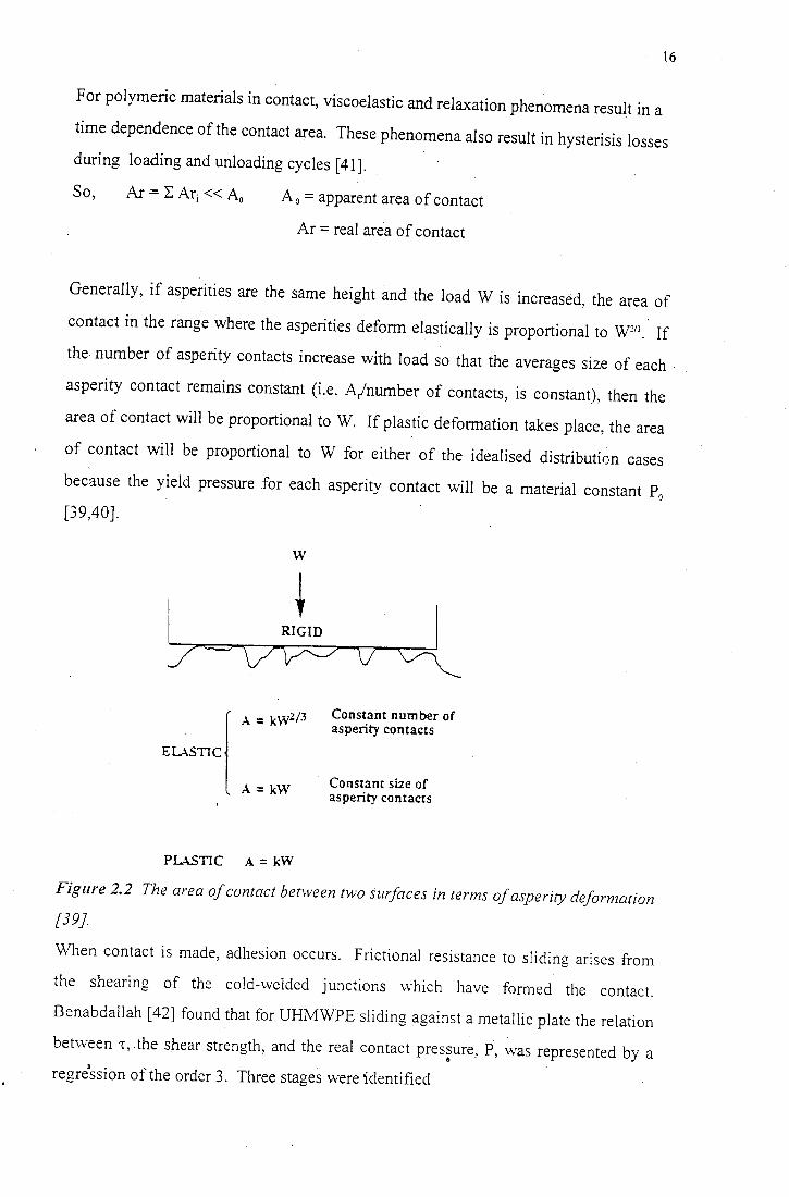
Generally, if asperities are the same height and the load W is increased, the area of
contact in the range where the asperities deform elastically is proportional to W213 • If
the number of asperity contacts increase with load so that the averages size of each
asperity contact remains constant (i.e. A/number of contacts, is constant), then the
area of contact will be proportional to W. If plastic deformation takes place, the area
of contact will be proportional to W for either of the idealised distribution cases
because the yield pressure for each asperity contact will be a material constant P0
[39,40].
w
~v
A= kW213
A= kW
PLASTIC A = kW
Constant number of asperity contacts
Constant size of asperity contacts
Figure 2.2 The area of contact between two surfaces in terms of asperity deformation
[39].
When contact is made, adhesion occurs. Frictional resistance to sliding arises from
the shearing of the cold-welded junctions vv-hich have formed the contact.
Benabdallah [ 42] found that for UHMWPE sliding against a metallic plate the relation
between -r, the shear strength, and the real contact pres~ure, P, vvas represented by a
regression of the order 3. Three stages werddentified
1. A decrease in -r when asperities deform elastically
2. The transitional -r remains almost constant when P approaches the same value as
the yield stress of the UHMWPE material
3. An increase in -r when asperities deform plastically.
It was also found that the initial roughness of the plastic sample plays a significant
role in determining the static yield strength [42].
2.1.3 Adhesion Theory of Friction
17
Solids adhere to one another and a force is thus required to make one body slide
across another. This force is known as the frictional force which is associated with µ,
the coefficient of friction. The following observations concerning frictional force
were made by Amontons:
(a) The frictional force is independent of area
(b) The frictional force is directly proportional to the normal load.
Polymers do not obey Amontons' laws to any large extent and for a wide variety of
loads, friction has been found to vary with load as follows:
F=kXn
or
µ=FIX= k X (n-1)
where F is the frictional force,
X is the normal load
µ is the coefficient of friction
and n is a constant
for branched polyethylene, n-1 is about -0.26
Generally friction decreases for increasing load. The true area of contact must equal a -
constant multiplied by load X. If there is an exponential distribution of asperity
heights independent of the mode of deformation of the asperities, or the shape of the
asperities, then there must be exact proportionality between the load and the true area
of contact [43].
18
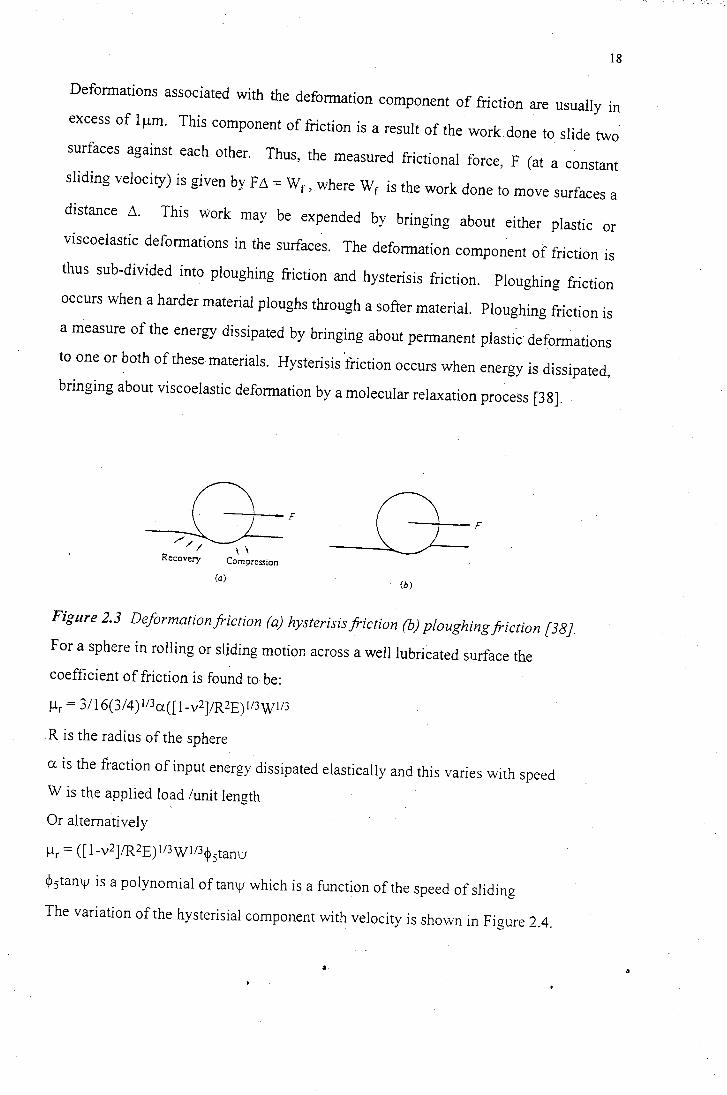
Deformations associated with the deformation component of friction are usually in
excess of 1 µm. This component of friction is a result of the work done to slide two
surfaces against each other. Thus, the measured frictional force, F (at a constant
sliding velocity) is given by Fb. = Wr, where Wr is the work done to move surfaces a
distance 6. This Work may be expended by bringing about either plastic or
viscoelastic deformations in the surfaces. The deformation component of friction is
thus sub-divided into ploughing friction and hysterisis friction. Ploughing friction
occurs when a harder material ploughs through a softer material. Ploughing friction is
a measure of the energy dissipated by bringing about permanent plastic deformations
to one or both of these materials. Hysterisis friction occurs when energy is dissipated,
bringing about viscoelastic deformation by a molecular relaxation process [38].
F
Recovery Compression
(a) (b)
Figure 2.3 Deformation.friction (a) hysterisisfriction (b) ploughing.friction [38].
For a sphere in rolling or sliding motion across a well lubricated surface the
coefficient of friction is found to be:
µr = 3116(314) 113a([ l-v2]/R2E) 113W113
R is the radius of the sphere
a is the fraction of input energy dissipated elastically and this varies with speed
W is the applied load /unit length
Or alternatively
µr = ([1-v2]fR2E)ll3WI/3~ 5tamv
~5tamv is a polynomial of tamv which is a function of the speed of sliding
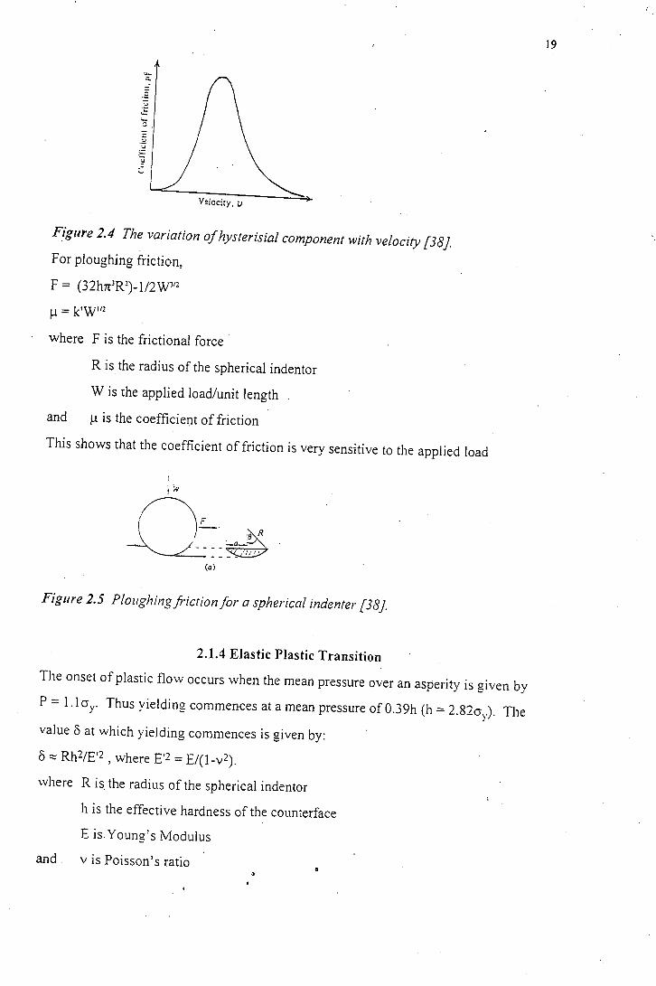
The variation of the hysterisial component with velocity is shown in Figure 2.4.
Velocity, u
Figure 2.4 The variation of hysterisial component with velocity [38].
For ploughing friction,
F = (32hn3R2)-I/2W312
µ =k'W 112
where F is the frictional force
R is the radius of the spherical indenter
W is the applied load/unit length
and µ is the coefficient of friction
This shows that the coefficient of friction is very sensitive to the applied load
(a)
Figure 2.5 Ploughing friction for a spherical indenter [38].
2.1.4 Elastic Plastic Transition
The onset of plastic flow occurs when the mean pressure over an asperity is given by
P = 1.1 cry. Thus yielding commences at a mean pressure of 0.39h (h = 2.82cry). The
value 8 at which yielding commences is given by:
8 :::::: Rh2/E'2 , where E'2 = E/(l-v2).
where R is the radius of the spherical indenter
h is the effective hardness of the counterface
Eis Young's Modulus
and vis Poisson's ratio
19
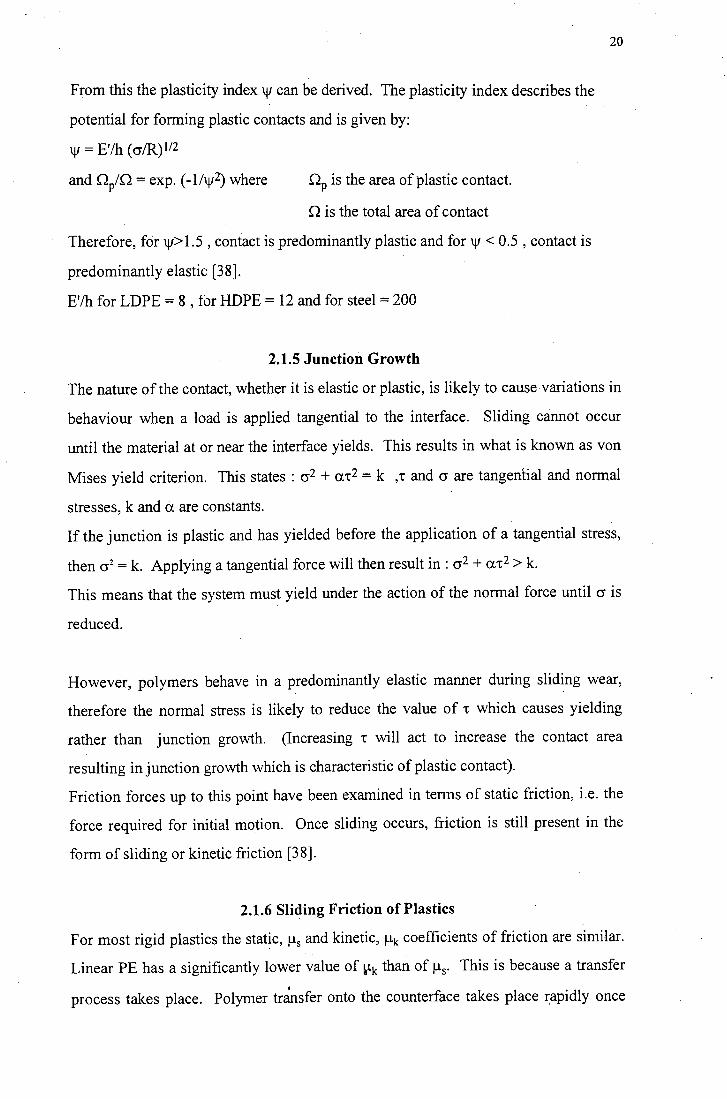
From this the plasticity index 'V can be derived. The plasticity index describes the
potential for forming plastic contacts and is given by:
'V = E'/h ( cr/R) 112
and QP/Q =exp. (-lhv2) where QP is the area of plastl.c contact.
Q is the total area of contact
Therefore, for w> 1.5 , contact is predominantly plastic and for 'V < 0.5 , contact is
predominantly elastic [38].
E'/h for LDPE = 8 , for HDPE = 12 and for steel= 200
2.1.5 Junction Growth
20
The nature of the contact, whether it is elastic or plastic, is likely to cause variations in
behaviour when a load is applied tangential to the interface. Sliding cannot occur
until the material at or near the interface yields. This results in what is known as von
Mises yield criterion. This states : cr2 + m:2 = k ,'t and cr are tangential and normal
stresses, k and a are constants.
If the junction is plastic and has yielded before the application of a tangential stress,
then cr2 = k. Applying a tangential force will then result in: cr2 + a't2 > k.
This means that the system must yield under the action of the normal force until cr is
reduced.
However, polymers behave in a predominantly elastic manner during sliding wear,
therefore the normal stress is likely to reduce the value of 't which causes yielding
rather than junction growth. (Increasing 't will act to increase the contact area
resulting in junction growth which is characteristic of plastic contact).
Friction forces up to this point have been examined in terms of static friction, i.e. the
force required for initial motion. Once sliding occurs, friction is still present in. the
form of sliding or kinetic friction [38].
2.1.6 Sliding Friction of Plastics
For most rigid plastics the static, µ5 and kinetic, µk coefficients of friction are similar.
Linear PE has a significantly lower value of ~k than of µs. This is because a transfer
process takes place. Polymer tr~nsfer onto the counterface takes place rapidly once
)
21
sliding has been initiated. As this process continues, the transfer film becomes
smooth. The initial sliding orients this polymer so that the polymer chains lie parallel
to the sliding direction. Because of the molecularly smooth profile of polyethylene,
the forces required to form this smooth ori~nted film are low. This results in a
reduction of the frictional forces during sliding because, effectively a smooth polymer
surface slides against another smooth polymer surface [38].
22
2.2 Wear
2.2.1 Introduction
Wear is a continuous inexorable process associated with two or more materials
moving in contact with one another. It involves the displacement of material from a
surface and this may occur by several mechanisms [43]. The most common modes
are:
• adhesive wear
• abrasive wear
• surface fatigue
• corrosive wear
23
2.2.2 Adhesive Wear
This is the most important of the wear processes as it occurs in all wear situations.
When two surfaces touch and support a normal load, atoms come into contact and so
the forces between the atoms interact [44,45]. For ceramics these interatomic forces
will be valency bonds, for polymers they may be Van der Waal's forces, electrostatic
forces or hydrogen bonds. Increasing the applied load, increases the likelihood of
strong interatomic bonding. When two surfaces are atomically clean, extremely
strong bonding may occur [45]. Gong et al. [46] suggested that, if the chemical
activity of the counterface is strong, the chemical bonds between the first layer of the
transfer film and the substrate will result in strong adhesion between the first layer of
the film and the substrate. However, the adhesion between the second and third layers
of the transfer film will still be poor. This can result in the transfer layer being
detached from the surface of the counterface. For sliding to occur the interfacial
bonds must be broken and shear must take place in order to rupture the adhesive
bonds at the interface. An adhesive interaction is developed at the interface during
this shear process.
The strength of the individual structural elements in the surface layers of the material ,
may be overcome at the onset of sliding. This results in fracture at the start of the
frictional interaction [ 4 7]. In practice, the adhesive bonds seldom rupture at the
interface and the bonds of the cohesively weaker material rupture instead. The
fracture products that result from this process form a third body and a transferred layer
may be deposited on the surface of the cohesively stronger material. Fracture does not
always occur and sometimes the softer material will "find" a flaw in the harder
material and cause this portion of the harder material to be removed. The transferred
fragment may be back-transferred, or alternatively it may be abraded by other features
of the rubbing surface. It may also become involved in the sliding process as a third
body. For ceramic fragments, these are likely to cause the breakdown of any transfer
film and this results in increased wear. The wear mechanism will then be abrasive
[45]. For polymer fragments, the third body will form part of the transferred layer
which is deposited on the cohesively stronger material. There is usually a running in
24
period of polymer wear following which steady state wear (in which the wear rate
almost always becomes constant) is established.
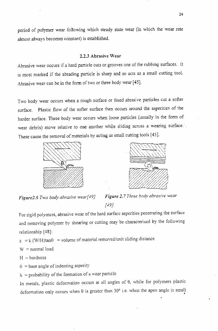
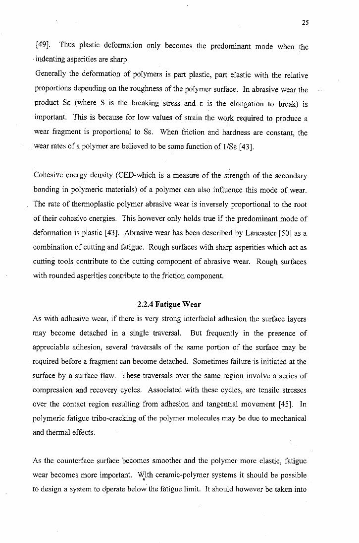
2.2.3 Abrasive Wear
Abrasive wear occurs if a hard particle cuts or grooves one of the rubbing surfaces. It
is most marked if the abrading particle is sharp and so acts as a small cutting tool.
Abrasive wear can be in the form of two or three body wear [ 45].
Two body wear occurs when a rough surface or fixed abrasi.ve particles cut a softer
surface. Plastic flow of the softer surface then occurs around the asperities of the
harder surface. Three body wear occurs when loose particles (usually in the form of
wear debris) move relative to one another while sliding across a wearing surface.· .
These cause the removal of materials by acting as small cutting tools [ 45].
Figure2.6 Two body abrasive wear[49}. Figure 2. 7 Three body abrasive wear
[49}.
For rigid polymers, abrasive wear of the hard surface asperities penetrating the surface
and removing polymer by shearing or cutting may be characterised by the following
relationship [ 48]:
z = k (W/H)tan8 =volume of material removed/unit sliding distance
W = normal load
H =hardness
e = base angle of indenting asperity
k =probability of the formation of a \Vear particle
In metals, plastic deformation occurs at all angles of 8, while for polymers plastic
deformation only occurs "vhen 8 is greater than 30° i.e. when the apex angle is small •
25
[ 49]. Thus plastic deformation only becomes the predominant mode when the
· indenting asperities are sharp.
Generally the deformation of polymers is part plastic, part elastic with the relative
proportions depending on the roughness of the polymer surface. In abrasive wear the
product Sg (where S is the breaking stress and g is the elongation to break) is
important. This is because for low values of strain the work required to produce a
wear fragment is proportional to Sf:. When friction and hardness are constant, the
wear rates of a polymer are believed to be some function of 1/Sg [ 43].
Cohesive energy density (CED-which is a measure of the strength of the secondary
bonding in polymeric materials) of a polymer can also influence this mode of wear.
The rate of thermoplastic polymer abrasive wear is inversely proportional to the root
of their cohesive energies. This however only holds true if the predominant mode of
deformation is plastic [43]. Abrasive wear has been described by Lancaster [50] as a
combination of cutting and fatigue. Rough surfaces with sharp asperities which act as
cutting tools contribute to the cutting component of abrasive wear. Rough surfaces
with rounded asperities contribute to the friction component.
2.2.4 Fatigue Wear
As with adhesive wear, if there is very strong interfacial adhesion the surface layers
may become detached in a single traversal. But frequently in the presence of
appreciable adhesion, several traversals of the same portion of the surface may be
required before a fragment can become detached. Sometimes failure "is initiated at the
surface by a surface flaw. These traversals over the same region involve a series of
compression and recovery cycles. Associated with these cycles, are tensile stresses
over the contact region resulting from adhesion and tangential movement [ 45]. In
polymeric fatigue tribe-cracking of the polymer molecules may be due to mechanical
and thermal effects.
As the counterface surface becomes smoother and the polymer more elastic, fatigue
wear becomes more important. With ceramic-polymer systems it should be possible •
to design a system to dperate below the fatigue limit. It should however be taken into
26
account that surfaces are not ideally smooth, and thus some asperities will experience
stresses well above the fatigue limit. The environment can also have an effect on
crack propagation [43]. Shallow pits and small cracks have been observed to align
perpendicular to the sliding direction in the UHMWPE after prolonged sliding [43].
2.2.5 Corrosive Wear
Corrosive wear or stress corrosion is associated with a chemically active medium in
the presence of an applied stress. Cracking can' occur at stresses far below critical in l
the presence of environmental factors. Chemicaf degradation - possibly in the form of
chain scission can profoundly influence.polymer wear [43].
This is an important wear process but it is unclear as to the exact role of the chemical
reactions as they differ depending on the chemical content of the tribological system.
27
2.3 Polymer Properties Affecting Friction and Wear
2.3.1 Introduction
The mechanical properties of a polymer are dependent on the chem!cal and physical
nature of the polymer. The mechanical properties are also affected by the
environment in which the polymer is used. Properties such as chain branching and
cross-linking, chain length and crystallinity of the polymer are linked to its
mechanical properties.
The mobility of polymer molecules has a critical effect in the friction and wear
behaviour of the polymer. Crosslinking results in a more tightly bound network I
which in turn results in decreased elongation to break and increased hardness. The
presence of crosslinks prevents the easy drawing out of the molecules which occurs
during the formation of a transfer film on the counterface [51,52].
Orientation effects can change the mechanical properties of a polymer and
subsequently affect wear rates at certain orientations of the polymer molecules. Free
solidified polymer melts and pressed sheets are largely free from orientation. Drawn
or hydrostatically extruded polymers are anisotropic. Anisotropic polymers have high
wear rates when the chains are oriented normal to the direction of sliding. This is
because the polymers are strong in the direction of orientation. Polymers are weak in
the direction normal to orientation and sliding against this direction makes the
polymers more susceptible to wear.
2.3.2 Viscoelasticity
Viscoelastic is the term used to describe the mechanical response of materials which
exhibit both the springiness associated with elastic solids and the viscous flow
associated with fluids [53]. This phenomena is associated with long and short range
rearrangements of long-chain molecules. Creep and stress relaxation are characteristic
of viscoelastic behaviour. Polymers are viscoelastic and therefore deformation is
dependent on strain rate as well as temperature.
28
For a sliding speed v and a corresponding frequency f, at which the adhesion term
reaches its maximum value, the critical length involved in the sliding process ( 1 = v/f)
is 50 A. This value is comparable with the length of a segment of molecules. Thus it
appears that the adhesion process of friction occurs on a molecular scale and the time
and temperature dependent properties of friction are closely related to the viscoelastic
properties of the polymer [54,55].
2.3.3 Mechanical Properties
Mechanical properties such as hardness, elastic modulus, Poisson's ratio, yield stress
and elongation to break control the deformation of polymeric materials.
In adhesive wear, the frictional force is the product of the shear stress 't and the real
area of contact. The real area of contact is largely governed by the mechanical
properties of the polymer. There is evidence that it is the mechanical properties of the
polymer that govern frictional losses in the consideration of the ploughing component
of friction [56]. It is however important to note that although the mechanical
properties of a polymer are an important factor in determining wear behaviour, a
detailed knowledge of the mechanical properties does not allow an accurate prediction
of the level of wear.
29
2.4 Wear ofUHMWPE
2.4.1 Introduction
UHMWPE is a semicrystalline polymer which, as a result of its excellent wear
properties is used in many varying applications. Very high molecular :weight
polyethylene is available as prepared by the Ziegler process. These materials have
average molecular weights in the range 1-5 E6. They are processed in the rubbery
phase because difficulties with decomposition are encountered in the molten st51te.
They are linear molecules with densities of about 0.94g/cm3. Difficulties with
crystallisation of large molecules results in the yield strength and stiffness (which are
dependent on the degree of crystallinity) being worse than those obtained for linear
polyethylene of conventional weights. The high molecular weight materials have high
abrasion resistance and impact strength as well as good stress crack resistance and low
creep [36]. It is these properties that makes the high molecular weight variety of
polyethylene useful for orthopaedic implants.
2.4.2 Wear Modes
Abrasive and adhesive wear are the principal wear ·modes found in water lubricated
sliding wear of UHMWPE against metallic and ceramic counterfaces. On rough
surfaces it is generally believed that abrasion is the principal mechanism while
adhesion dominates on "smooth" surfaces [57]. Marcus et al. [43] found that for
rough metallic surfaces ( 0.3µm Ra ) microcutting and ploughing caused the initial
material removal after which the wear fragments were laid down in the form of a
transfer layer and adhesive wear became the dominant mechanism. This transfer film
results in very low wear rates at low load and low speed conditions. On smoother
surfaces, with Ra less than 0.05µm, no transfer layer is observed rather, polymer is
transferred to the surface as thin discontinuous patches [43]. It has been postulated
that these differences can be explained by considering the wear in terms of
macroscopic and microscopic wear mechanisms [1 ]. Microscopic asperity wear is
that which is likely to dominate the wear processes for rougher counterfaces. This
(abrasive or adhesive ) wear is associated with deformation of a nominally flat
30
polymer surface by repeated interactions with the microscopic asperities of the
counterface. For macroscopic asperity wear the peaks of the polymer surface are
typically up to 100 times larger than those of the asperities of smooth counterfaces.
These peaks are deformed by the applied load and this deformation results in surface
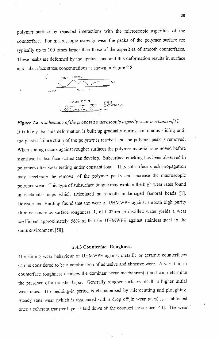
and subsurface stress concentrations as shown in Figure 2.8 .
:·.J2 .... ,,
. :·JOum ::l!JLY .... ~::(
.~--- ·ou:n _,
5i~ESS
.·. ·-· -~::.~co:~r;;~;.:~1s '\ .·::::::::: ,,.,.-...:..:::.-:..-.._ .... :::::: .. ,.----
Figure2.8 a schematic of the proposed macroscopic asperity wear mechanism[J}.
It is likely that this deformation is built up gradually during continuous sliding until
the plastic failure strain of the polymer is reached and the polymer peak is removed.
When sliding occurs against rougher surfaces the polymer material ~s removed before
significant subsurface strains can develop. Subsurface cracking has been observed in
polymers after wear testing under constant load. This subsurface crack propagation
may accelerate the removal of the polymer peaks and increase the macroscopic
polymer wear. This type of subsurface fatigue may explain the high wear rates found
in acetabular cups which articulated on smooth undamaged femoral heads [1].
Dowson and Harding found that the wear of UHMWPE against smooth high purity
alumina ceramics surface roughness Ra of 0.02µm in distilled water yields a wear
coefficient approximately 56% of that for UHMWPE against stainless steel in the
same environment [58].
2.4.3 Counterface Roughness
The sliding wear behaviour of UHMWPE against metallic or ceramic counterfaces . . .
can be considered to be a combination of adhesive and abrasive wear. A variation in
counterface roughness cha~ges the dominant wear mechanism(s) and can determine
the presence of a transfer layer. Generally rougher surfaces result in higher initial
wear rates. The bedding-in period is characterised by microcutting and ploughing.
Steady state wear (which is associated with a drop off,in wear rates) is established
once a coherent transfer layer is laid down o'n the counterface surface [43]. The wear '
31
of rough surfaces is considered to be a microscopic wear mechanism whereby the
asperity peaks of the counterface are up to 100 times larger than those of the polymer
and act as cutting tools to cause polymer loss [1].
Smoother surfaces are thought to be characterised by adhesive wear [57]. There is no
coherent build up of transfer film on smooth metallic or ceramic surfaces [44,58].
Smooth metallic surfaces exhibit a small amount of lumpy transfer [43] while ceramic
surfaces show no evidence of transfer [58]. The wear of smooth surfaces is
considered to be a macroscopic w~ar mechanism whereby subsurface strains develop
as a result of the deformation of polymer asperity peaks. This strain is built up during
the sliding process until the plastic failure strain is reached and the polymer peak is
removed [1].
Hollander and Lancaster showed that the wear rate de_creases with increasing values of
average asperity radius [59]. In addition to this the wear rate has been found to be
directly proportional to the base angle of the cone of a hard iildentor. Bahadur and
Stiglich [57] have shown that the steady state wear rate increases rapidly with the
wear particle size on rough surfaces varying from r.m.s values of 0.51 µm to 24. lµm.
For rough surfaces, the wear particle size has been found to vary inversely with the
number of asperity peaks per mm, and to be directly proportional to the asperity angle
for water lubricated wear between UHMWPE and steel [57]. Rose et al found that for
bovine serum lubricated wear of UHMWPE sliding against steel, wear debris from
specimens with low wear rates tend to be wholly fibrous [51] while the debris from
specimens with high wear rates is coarse and granular [60]. These results were
confirmed by clinical retrieval· studies [ 61].
2.4.4 Grinding Direction
Marcus et al. [43] found that wear on cross-ground surfaces are more sensitive to
counterface roughness than those obtained on parallel ground surfaces. A uniform
coherent film was found to form relatively quickly when sliding takes place
perpendicular to the counterface grinding direction. This is believed to be because •
any material that is lost by shear can be accommodated in the valleys between the
32
asperities of the surface. Polymer transfer was found to be patchy when sliding
parallel to the counterface grinding direction [ 4 3].
2.4.5 Morphology
When HDPE slides against steel in water, wear takes place on the crystallographic a-c
plane i.e. normal to the b axis. The a-c plane is the boundary where the neighbouring
crystals slip over each other and in this way wear debris separates from the crystal
substrate. It is possible that water molecules may be absorbed on the a-c plane where
they act as a lubricant [62].
33
2.5 Wear in Prosthetic Implants
2.5.1 Introduction
The number of artificial hips implanted world-wide exceeds 500 000 annually [1].
These surgical implants must be able to bear the forces of normal patient activity,
while at the same time withstanding mechanical failure.
Most patients undergo total hip replacements (THR's) to combat some form of bone
disease such as rheumatoid arthritis or osteoarthrosis. The ideal life span required of
prostheses is of the order of 30 years. However, as hip replacements become more
common among younger patients, the life span required of THR' s is increasing. In
addition to this, the stresses placed on the THR's by a younger more active person far
exceed those of older patients. The poor durability of prosthetic hip implants leads
surgeons to consider alternatives wherever possible for younger patients [62].
The materials used in THR's must therefore be able to withstand the physiological
environment as well as the substantial loads imposed on the hip joint. The 30 year
life requirement of the THR's implies that the materials need to be fatigue resistant
within the physiological environment. This means maintaining their properties at
temperatures of 3 7°C and in the presence of synovial fluid or blood plasma. They
must be biocompatible, i.e. they must not produce inflammatory reactions in the body
[63]. In addition to this, prosthesis materials must withstand loading without arty
substantial dimension changes and without brittle failure. Furthermore, creep, fatigue
and stress corrosion should be minimal [63].
In general the materials used in THR's are biostable and exhibit minimal degradation.
Sliding of the two components against one another causes wear and this produces
wear debris. It is this wear debris which is a commonly the cause of failure in THR's
[1-12]. Particles of the UHMWPE wear debris are transported to the hard and soft
tissue adjacent to the implant. These particles activate inflammatory cells
(macrophages). The activated macrophages stimulate osteoclasts to cause local bone
resorption or bone thinning around the implant.
34
Thus the choice of materials is critical to the success of the implant. Other factors to
consider once the materials have been chosen are: surface finish of the materials,
cleaning and sterilisation techniques and fabrication routes and their effect on
biostability and service life [64].
35
2.5.2 Materials in Use
~ificial hip joints consist of a femoral component which attaches to the femur. The
femoral head articulates in the acetabular component which in tum attaches to the
acetabulum. The femoral component bears the load on the hip joint and the material
of this component needs to be able to sustain loading without brittle failure. The
articulation of the femoral head in the acetabular cup demands a bearing couple with
very good tribological properties and superb fatigue resistance.
The materials initially used for low friction prostheses were a combination of 316L
stainless steel for the femoral components and ultra high molecular weight
polyethylene (UHMWPE) for the acetabular components. Steel was used because of
its load-bearing capacity and corrosion resistance. The UHMWPE was used for its
good tribological properties and its creep resistance when compared to other
biomedical polymers. However, by the late 60's these THR's started to show limits in
life expectancy. This was largely due to the high loosening rates of metal-on-metal
systems and the high wear rates of the metal-on-plastic systems [65].
Advances on the materials front have introduced Co-Cr-Mo alloys, Ti-6Al-4V alloys
and "commercially pure" titanium. These are less susceptible to corrosion and wear in
the physiological environment than stainless steels that has been used in the past (66].
However, recent research has shown that titanium alloys have high rates of premature
failure [67-72].
Alumina ceramics were introduced as joint replacement materials in the early l 970's.
They are biocompatible and have low wear rates and good friction characteristics [73].
Alumina is most commonly used in THR's in conjunction with UHMWPE. This is
because alumina ceramics are less dependent on the exact nature of the lubricant than
the metallic materials mentioned. In addition to this, the superior wettability of
ceramics when compared to metals results in good wear resistance [66].
Concern over the production of UHMWPE particles and their effect on macrophage ~
response led to the production of ceramic:ceramic THR's. Alumina on alumina
36
systems have excellent wear rates and can have up to 4 000 times less wear debris
than the equivalent metal on UHMWPE design. This combination is shown to have
the greatest wear resistance, the least wear debris and the longest life. This is however
dependent on several factors. These are :
• the size of the femoral head must not be too small or it may break.
• articular surfaces must be accurately designed with a clearance of 15 - 40µm
between the two components.
• the surgeon .µmst not hammer the acetabular cup as this may result in stress
raisers.
• the cup must not be positioned too vertically because this may result in a point
load which will dramatically increase wear [74].
Alumina prostheses are therefore difficult to position surgically and adjustments are
very difficult to make. Generally the pair is manufactured as "matched". That is, the
implant has specially paired components with tighter dimensional tolerances. In
addition to this, these implants are more costly [74] and are also susceptible to so
called marginal loosening situations such as neck-cup impingement and impact forces.
The high stiffness of the alumina has a tendency to cause bone shearing and
subsequent failure of the implant at the bone-implant interface [74].
Further advances in THR surgery have led to the production of femoral components
with modular stems. Modular stems enable the variation of the neck length and the
head size of.the femoral component and also allow a mixed alloy system [75].
One particularly favoured combination is the titanium alloy stem with the Co-Cr-Mo
head. The Ti alloy is chosen for porous coated uncemented stems because of its
relatively low elastic modulus, while Co-Cr-Mo is favoured for the head because of its
superior wear characteristics. Ther.e is however a certain amount of galvanic and
crevice corrosion resulting from coupling these two metals in the physiological
medium. This corrosion results in the production of debris and a reduction in
mechanical properties of the implants [75].
37
Modular systems have been used with Co-Cr-Mo stems and alumina heads [77]. This
eliminates the corrosion while providing good wear properties at the articulating
surfaces.
More recently partially stabilised zirconia (PSZ) ceramics have been considered as an
alternative to alumina. PSZ is tougher than alumina and has a finer grain size which
allows the production of a finer surface finish. Preliminary tests have shown zirconia
to be biostable.
Thus it would appear that the best compromise of wear and mechanical properties at
this stage is the ceramic: UHMWPE system. Wear debris remains a significant
problem resulting in more failures than any one factor. Reducing the production of
wear debris would significantly increase the life of total hip replacements (THR's).
Investigating the wear behaviour of the ceramic:UHMWPE system by testing alumina
and zirconia against UHMWPE may provide important information regarding the
nature of this wear process.
2.5.3 UHMWPE Wear in Implants
The maximum principal stress in UHMWPE caused by normal walking is usually less
than lOMPa in total hip replacements (THR's). Thus the maximum shear stress
occurs at the surface of the UHMWPE component. Studies of retrieved UHMWPE
components [ 1] have revealed the existence of large amounts of residual plastic strain
within the surface region of the acetabular components. In the acetabular/femoral
head contact, only the microscopic asperities are deformed plastically, while the
nominal contact is elastic. Wang et al. [78] postulated that, during walking every
contact asperity on the UHMWPE will experience repeated cyclic deformation by the
passing asperities on the femoral head. In this way an incremental residual plastic
strain 8i:: is built into each contact spot with every interaction of this kind. Failure will
therefore occur when the ductility of the material within each contact spot has been
exhausted. Thus by assuming i::c as the critical strain for UHivfWPE under these
conditions, a wear particle may be produced when the accumulated plastic strain after . .
nc asperity encounters reaches i::c so 8i::nc = i::c
38
Assuming a fully plastic asperity situation and a uniform distribution of N asperities
with equal height and equal tip radius. From the random walk theory [79], there will
be N contact spots at any given moment and N 112 passes sweeping through the same
spot per walking cycle. By relating this to the true area of contact and the volume of
the wear particles, Wang et al. [78] found~ V oc P312 R/12 1/(cr/12cu).
where V is the total volume of wear particles produced
P is the average applied load per contact cycle
Ra is the centre-line-average roughness of the femoral head
cru is the ultimate tensile strength
Eu is the elongation at break
cruEu is representative of the strain energy at break in a tensile test.
It was concluded that the tensile rupture energy or toughness is the most important
propert-y determining volumetric wear rate [78].
2:s.4 Wear Debris Effects
The major concern relating to the long-term clinical performance of implants is the
tissue reactions which are caused by UHMWPE debris. Fine UHMWPE particles that
are transported to the hard and soft tissue surrounding the joint cause chronic
inflammation reactions [80] around the joint and result in bone resorption [7].
UHMWPE particles activate macrophages (inflammatory cells) which stimulate
osteoclasts to cause local bone resorption [1]. In 9 revision operations documented
by W J Maloney et al. [81], in which the joints had failed as a result of osteolysis or
bone loss, the osteolytic regions were covered by a fibrous membrane. Analysis of
the histological sections revealed sheets of macrophages within this fibrous
membrane. Intracellular polyethylene particles ranging from submicron size to about
3 µm were identified. Larger particles of polyethylene were seen in association with
multinucleated giant cells. The reactions to the wear debris are dependent on the size
and morphology of the wear debris. Particle size determines the type of response to
the wear debris. As the particle size decreases, the relative surfaces area available for
physical and chemical reactions increases. This results in an increased potential for
detrimental reactions [82]. The composition [83], rate of production [84], particle size •
[85], shape [86] and surface characteristics [87] affect the biological response of the
39
implant. Component loosening and tissue reaction to wear debris are two of the most '
common causes of implant failure [88].
Osteolysis or bone loss as a resul't of local bone resorption is a common complication
of total hip replacements. Maloney et al. [89] reported femoral osteolysis in
radiographically stable uncemented THR's. Biopsy material demonstrated particulate
metal and polyethylene (PE) debris with focal aggregates and macrophages. W J
Maloney et al. reported that in investigating 15 hips with considerable pelvic
osteolysis, loss of the femur was most commonly seen in the region of the greater or
lesser trochanter. In 9 of the revision operations the osteolytic area was covered by a
fibrous-tissue membrane. Sheets of macrophages were found within the fibrous
membrane. There were more PE particles than metallic particles [90].
Particulate debris can be generated at the hip articulation and at other locations. This
debris has the potential to gain access to the effective joint space (effective joint space
is the entire bone-implant interface which is accessible to joint fluid, [91]) and
stimulating osteolysis. The ease with which wear debris gains access to the interface
between the implant and the bone is determined in part by the integrity of the bone
implant interface [90]. Osteolysis rarely results in pain and substantial bone loss can
occur before the fixation of the implant is substantially compromised. Lee et al. found
that metallic debris found in periarticular tissues of failed, non-infected cemented hip
joints ranged in size from 0.8 to l .Oµm in the short dimension and 1.5 to 1.8µm in the
long direction. Polymer debris for the same samples was found to vary from 2 to 4
µm in the short dimension and 8 to 13 µm in the long dimension. Shanbag et al.
found that most PE and mineral particles present in interfacial tissue are submicron
size. Fragments larger than 7 µm are generally assumed to be too large to be
phagocytosed by macrophages [92] and contribute minimally if at all to the biological
responses leading to osteolysis [93,94]. Finer particles are believed to stimulate
macrophages [93-95].
40
2.6 Lubrication
2.6.1 Introduction
Lubrication is a common method used to reduce wear. The lubricating medium
separates the two interacting surfaces and assists the sliding of the respective surfaces
by. reducing the friction between them. A good lubricant should therefore prevent
solid-solid contact and should have a low shear strength to ensure low friction. A
liquid is the best lubricant because it can be sheared an infinite number of times
without failing from wear or fatigue [96]. There are various types of lubricating
conditions and these are determined by the nature of the wear process.
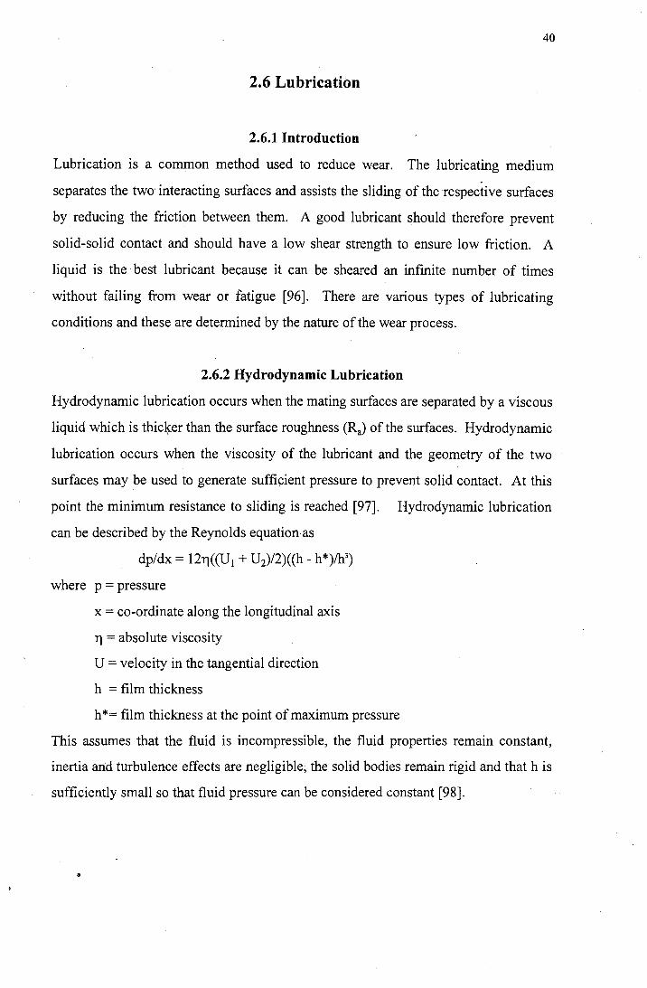
2.6.2 Hydrodynamic Lubrication
Hydrodynamic lubrication occurs when the mating surfaces are separated by a viscous
liquid which is thicl~er than the surface roughness (RJ of the surfaces. Hydrodynamic
lubrication occurs when the viscosity of the lubricant and the geometry of the two
surfaces may be used to generate sufficient pressure to prevent solid contact. At this
point the minimum resistance to sliding is reached [97]. Hydrodynamic lubrication
can be described by the Reynolds equation as
dp/dx = 12ri((U1 + U2)/2)((h - h*)/h3)
where p = pressure
x = co-ordinate along the longitudinal axis
ri = absolute viscosity
U = velocity in the tangential direction
h = film thickness
h*= film thickness at the point of maximum pressure
This assumes that the fluid is incompressible, the fluid properties remain constant,
inertia and turbulence effects are negligible, the solid bodies remain rigid and that h is
sufficiently small so that fluid pressure can be considered constant [98].
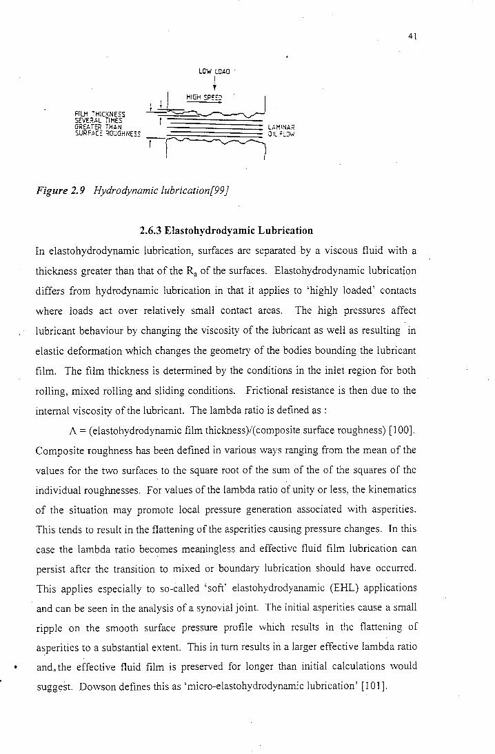
FILM THICKNESS SEVERAL TIMES GREATER iHAN SURFAC~ ROUGHNESS
LOW LOAO ·
I '
~~ t~~~~~~ :::;; LAMINAR ~O'L.'COW
Figure 2.9 Hydrodynamic lubrication[99 J
2.6.3 Elastohydrodyamic Lubrication
41
In elastohydrodynamic lubrication, surfaces are separated by a viscous fluid with a
thickness greater than that of the Ra of the surfaces. Elastohydrodynamic lubrication
differs from hydrodynamic lubrication in that it applies to 'highly loaded' contacts
where loads act over relatively small contact areas. The high pressures affect
lubricant behaviour by changing the viscosity of the lubricant as well as resulting in
elastic deformation which changes the geometry of the bodies bounding the lubricant
film. The film thickness is determined by the conditions in the inlet region for both
rolling, mixed rolling and sliding conditions. Frictional resistance is then due to the
internal viscosity of the lubricant. The lambda ratio is defined as :
A = ( elastohydrodynamic film thickness)/( composite surface roughness) [ 100).
Composite roughness has been defined in various ways ranging from the mean of the
values for the two surfaces to the square root of the sum of the of the squares of the
individual roughnesses. For values of the lambda ratio of unity or less, the kinematics
of the situation may promote local pressure generation associated with asperities.
This tends to result in the flattening of the asperities causing pressure changes. In this
case the lambda ratio becomes meaningless and effective fluid film lubrication can
persist after the transition to mixed or boundary lubrication should have occurred.
This applies especially to so-called 'soft' elastohydrodyanamic (EHL) applications
and can be seen in the analysis of a synovial joint. The initial asperities cause a small
ripple on the smooth surface pressure profile which results in the flattening of
asperities to a substantial extent. This in turn results in a larger effective lambda ratio
a and., the effective fluid film is preserved for longer than initial calculations would
suggest. Dowson defines this as 'micro-elastohydrodynamic lubrication' [101).
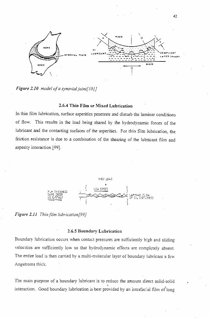
42
\
. COWPLIAHT SY HOVI AL FLU 10
LAYE~ {rou9rt)
RIGID
tJ
I
Figure 2.10 model of a synovialjoint[JOJ]
2.6.4 Thin Film or Mixed Lubrication
In thin film lubrication, surface asperities penetrate and disturb the laminar conditions
of flow. This results in the load being shared by the hydrodynamic forces of the
lubricant and the contacting surfaces of the asperities. For thin film lubrication, the.
friction resistance is due to a combination of the shearing of the lubricant film and
asperity interaction l99).
Figure 2.11 Thin/Um lubrication[99}
2.6.5 Boundary Lubrication
Boundary lubrication occurs when contact pressures are sufficiently high and sliding
velocities are sufficiently low so that hydrodynamic effects are completely absent.
The entire load is then carried by a multi-molecular layer of boundary lubricant a few
Angstroms thick.
The main purpose of a boundary lubricant is to reduce the amount direct solid-solid
interaction. Good boundary lubrication is best provided by an interfacial film of°long
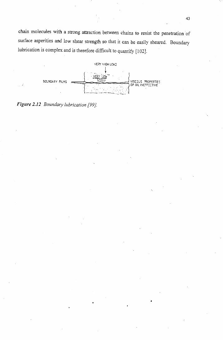
43
chain molecules with a strong attraction between chains to resist the penetration of
surface asperities and low shear strength so that it can be easily sheared. Boundary
lubrication is complex and is therefore difficult to quantify [I 02].
VERY HIGH LOAD
SOUNOARY FILMS
'·· ... ~i. VEP.Y fo;r . ·
··. ---s;:g .· VISCOUS ~oP:;:<nE~ ==:::>. -.. =-_.-=. ::::... . . .. . . < . . OF Oil INE:=:=~Ci!VE
' -.. . . . . .· .-.... ,. ..· .. : .· .... .. :.·, :
... -.. -~·~ .... ~- :.: '··•'' :.-~ .. ,.~~~·~-.: .. :.·,_:,,~::~ .. -~· -..
Figure 2.12 Boundary lubrication [99).
44
2.7 Lubrication of Implants
2.7.1 Introduction
In human skeletons, the limb segments articulate on one another or on the trunk
segments by means of synovial joints. In synovial joints, bone ends are hollow and
enlarged with a shell of approximately O.Smm-1.0mm thick supported on a system of
braced struts. The two shapes are more or less congruent and are spherical,
cylindrical or saddle in form. The bone ends are covered with sufficient articular
cartilage to ensure that articular cartilage articulates on articular cartilage. Articular
cartilage varies over a thickness of 3-4mm and is seldom covitant over the joint
surface [l 03].
In the absence of load, the gap between the cartilage surfaces depends on the forms of
the underlying bones, the thickness of the cartilage layers and the relative positions of
the bone segments [103].
The ends of the bones are surrounded by a capsule or bursa which functions to keep
the synovial fluid in and the other fluids out. This capsule is lined with cells which
produce hyaluronic acid (the characteristic component of synovial fluid) [103].
The loads on hips and knees during walking vary in such a way that high loads
combine with low surface entrainment velocities, while low loads combine with
higher entraining velocities. When the femoral h~ad first encounters the acetabular
socket, a thick film of fluid separates the two surfaces. Friction is inversely related to
film thickness, so friction is low at this point. As the film is squeezed down under the
effect of heavy loading, the friction will increase. So for high loads/low velocities,
the only possible mechanism for supporting a film of fluid will be a squeeze film
action [104,105] ..
2.7.2 Articular Cartilage
Articular cartilage is a collagen fibre mesh in a gel of mucopolysaccharides attached
to proteins. Mucopolysaccharides are also known as glucosaminoglycans (GAG).
The protein core with GAG attached at several sites and branching out1 sideways from
45
the core is known as proteoglycan. Articular cartilage contains by weight
approximately 68 - 75 % water, 2 - 8 % GAG, 15 - 20 % collagen and I - 2 % protein.
GAG molecules contain carboxyl and sulphate groups which are negatively charged.
Electrical properties therefore affect the mechanical and transport properties of the
cartilage. Swelling pressure associated with water inside and adjacent to the cartilage
can also affect these properties. Collagen fibres are strong in tension and weak in
compression and are maintained in tension by the swelling pressure generated by the
aqueous gel of the proteoglycan [103].
Articular cartilage has two functions. Firstly, to distribute joint forces over the
underlying cartilage and secondly, to provide a bearing surface. For the first function,
the articular cartilage should have a minimum thickness and a stiffness between zero
and that of the bone. For the second function, low friction and low wear rates are
required. The repeated stresses on the joint must not cause irreparable mechanical
breakdown. There is a possibility that incipient fatigue failure excites a healing
response [ 103].
2.7.3 Synovial Fluid
The lubrication of synovial joints is complex and not easily understood. There ·are
several mechanisms of lubrication available to the synovial joint. Current models of
synovial fluid lubrication implement hydrodynamic lubrication assisted by the
secretion of synovial fluid from the cartilage into the space between interacting
cartilage surfaces. Synovial fluid causes either a thin layer of hyaluronic acid-protein
to be absorbed on the cartilage, or a concentrated gel to form in the loaded region (this
gel persists as a squeeze film) [103]. Hyaluronic acid is an alternating copolymer
which is largely responsible for the lubricating effect of the synovial joint [106].
· Proteoglycans which fom1 the matrix of the cartilage are chemically closely related to
the hyaluronic acid and protein in the synovial fluid. Proteolglycan is a protein core
with glycosaminoglycans (mucopolysaccharides) attached at several sites and
branching sideways from the core. These mucopolysaccharides also contain
negatively charged carboxyl and sulphate groups. It is likely that this protein core is
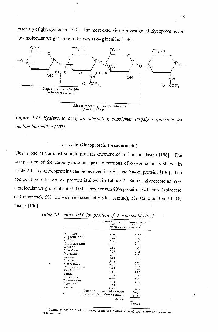
46
made up of glycoproteins [103]. The most extensively investigated glycoproteins are
low molecular weight proteins known as a- globulins [106].
coo-'(H20H \ O oyoo-
0
"" 0 I .B<I13> • ~ I .B0-4) I I
OH I NH OH I
: I I
-0 "-.J OH
I O=CCH3 : '----t------~'~--~----~ I
Repeating {iisaccharide I
in hyalu;onic acid i
I I I I
Also a repe:Hing disaccharide with ,8(1--4) linkage
HO
CHoOH ! -r-----o
I NH I
O=CCH3
0-
Figure 2.13 Hyaluronic acid, an alternating copolymer largely responsible for
implant lubrication [I 07].
a.1 - Acid Glycoprotein ( orosomucoid)
This is one of the most soluble proteins encountered in human plasma [I 06]. The
composition of the carbohydrate and protein portions of orosomucoid is shown in
Table 2.1. a.2 -Glycoproteins can be resolved into Ba- and Zn- a.2 proteins [106]. The
composition of the Zn- a 2- proteins is shown in Table 2.2. Ba- ar glycoproteins have
a molecular weight of about 49 000. They contain 80% protein, 6% hexose (galactose
and mannose), 5% hexosamine (essentially glucosamine), 5% sialic acid and 0.3%
fucose [I 06].
Table 2.1 Amino Acid Composition of Orosomucoid [106]
. .;.:5_nine
.-\..soa.r-...;.c acid c ::S\:lr.e G~u:acic ac:d G~yc.:.::ie =:isud..i.c.e isoieuci:J.e L~~ci..-ie !..:.·sme
?::.e::'.l viaian.i...'1.e ?:=l.G.e
3.63
o.oo !O. 73
o.3"'1
3 .:: : 5.03 0.65 3.9: .:.37
-'-.3o r.=s
:-~.--:osine r.99 \.~~ine :: . .3::
l·Jtal oi icino a.cid. :-esidues Total QI ca:oohydrate residues
·J. 5-; 3 . ..:.3 :.';)Q
: -·~..S
:. 7·? :.39
50.56
De!1.cit L::.:.!.
!00.00
• Gra:ns oi a.!:lino acid :-ecove:-ed from :!le hydroiysa.:e oi ~co g dry a.nd ash-free 0rosomucoid.
...... ~ .-<"':· ::~. :-
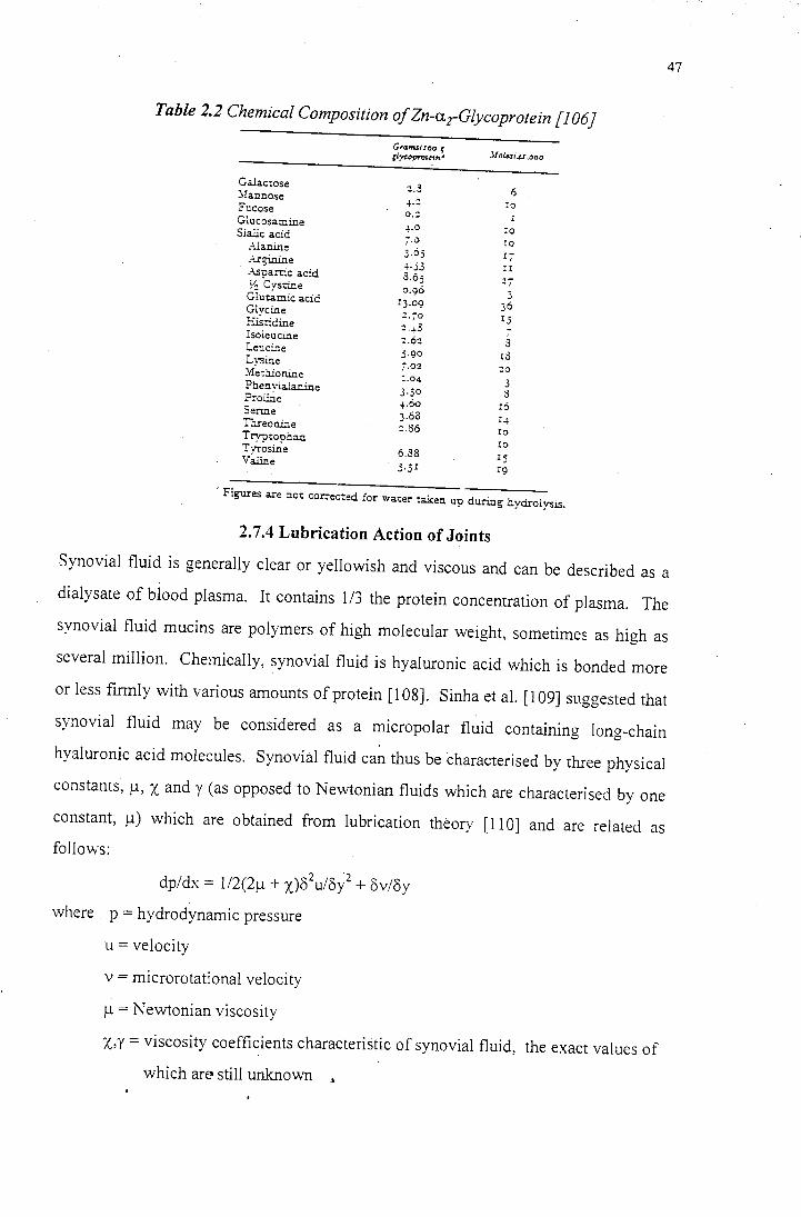
47
Table 2.2 Chemical Composition of Zn-arGlycoprotein [l 06]
GTanui.too f gJycopro1e1n• .llo!.ai.µ:,ooo
Galactose ::.3 6 :::.Iannose ... :: ro Fucose o.:: Glucasamine
4.0 ro Sia..iic acid 7.0 ro .-\.la nine 3.65 I-Arginine I
-+·53 II .-\.s'Oartic acid 8.65 ~~ "cystine 0.96 3 Gluumic acid
IJ.09 36 G!vcine H~tidine 2.70 Ij
:: . .J.3 -Isoleucine :.62 s Leu cine 5.90 r8 Lv~ine i.02 20 .Yf~thionine I.0.J. 3 Phenylalanine 3.30 8 Pro line ... Do r6 Serine 3.68 I.+ Threonine ::.86 IO Tryptophan
IO Tyrosine 6.38 rs Va.line j.jI r9
·Figures are n01: correc-::ed for water taken up during hydrolysis.
2.7.4 Lubrication Action of Joints
Synovial fluid is generally clear or yellowish and viscous and can be described as a
dialysate of blood plasma. It contains 1/3 the protein concentration of plasma. The
synovial fluid mucins are polymers of high molecular weight, sometimes as high as
several million. Chemically, synovial fluid is hyaluronic acid which is bonded more
or less firmly with various amounts of protein [108). Sinha et al. [109] suggested that
synovial fluid may be considered as a micropolar fluid containing long-chain
hyaluronic acid molecules. Synovial fluid can thus be characterised by three physical
constants, µ, x and y (as opposed to Newtonian fluids which are characterised by one
constant, µ) which are obtained from lubrication theory [110] and are related as
follows:
2 2 dp/dx = 1/2(2µ + x)o u/8y + 8v/8y
where p = hydrodynamic pressure
u =velocity
v = microrotational velocity
µ=Newtonian viscosity
x,y =viscosity coefficients characteristic of synovial fluid, the exact values of
which arn still unknown
48
2. 7.5 The Effect of Proteins on the Lubricating Function of Synovial Fluid
Linn and Radin [111] digested synovial fluid with hyaluronidase so that its viscosity
was reduced by breaking the chains of the hyaluronic acid which normally acts as a
viscosity raiser in synovial fluid. The digestion process resulted in a reduced
viscosity, but the ·coefficient of friction was found to be the same. Tryptic digestion
which breaks down proteins with minimal effect on viscosity was found to cause the
frictional coefficient to double from 0.0028 to 0.0054 (typically). It was concluded
that synovial fluid was acting as a boundary lubricant under conditions of constant
heavy loading. The same experiments were carried out by O'Kelly et al. [112] under
dynamic loading conditions. It was found that hyaluronic acid digestion reduced the
viscosity and increased the friction. From this it was concluded that under normal
walking dynamic c'ycles, fluid film lubrication of joints dominates, while under static
heavy loads, mixed lubrication prevails with boundary lubrication dominating [102].
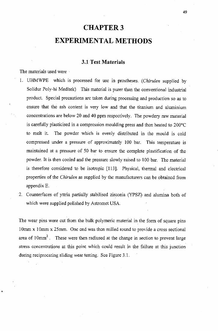
0
49
CHAPTER3
EXPERIMENTAL METHODS
3.1 Test Materials
The materials used were
1. UHMWPE which is processed for use in prostheses. ( Chirulen supplied by
Solidur Poly-hi Meditek) This material is purer than the conventional industrial
product. Special precautions are taken during processing and production so as to
ensure that the ash content is very low and that the titanium and aluminium
concentrations are below 20 and 40 ppm respectively. The powdery raw material
is carefully plasticised in a compression moulding press and then heated to 200°C
to melt it. The powder which is evenly distributed in the mould is cold
compressed under a pressure of approximately 100 bar. This temperature is
maintained at a pressure of 50 bar to ensure the complete plastification of the
powder. It is then cooled and the pressure slowly'raised to 100 bar. The material
is therefore considered to be isotropic [ 113]. Physical, thermal and electrical
properties of the Chirulen as supplied by the manufacturers can be obtained from
appendix E.
2. Counterfaces of yttria partially stabilised zirconia (YPSZ) and alumina both of
which were supplied polished by Astromet USA.
The wear pins were cut from the bulk polymeric material in the form of square pins
1 Omm x 1 Omm x 25mm. One end was then milled round to provide a cross sectional
area of 1 Omm2 • These were then radiused at the change in section to prevent large
stress concentrations at this point which could result in the failure at this junction
during reciprocating sliding wear testing. See Figure 3.1.
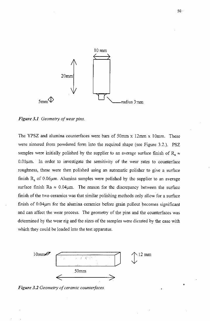
50
lOmm / '\. '\. /
/[\
20mm
\V
U "'--radius 3mm
Figure 3.1 Geometry of wear pins.
The YPSZ and alumina counterfaces were bars of 50mm x 12mm x lOmm. These
were sintered from powdered form into the required shape (see Figure 3.2.). PSZ
samples were initially polished by the supplier to an average surface finish of Ra :::;
O.Olµm. In order to investigate the sensitivity of the wear rates to counterface
roughness, these were then polished using an automatic polisher to give a surface
finish Ra of 0.06µm. Alumina samples were polished by the supplier to an average
surface finish Ra :::; 0.04µm. The reason for the discrepancy between the surface
finish of the two ceramics was that similar polishing methods only allow for a surface
finish of 0.04µm for the alumina ceramics before grain pullout becomes significant
and can affect the wear process. The geometry of the pins and the counterfaces was
determined by the wear rig and the sizes of the samples were dictated by the ease with
which they could be loaded into the test apparatus .
lOmrrP
.._I _______ O t12mm
50mm
< > Figure 3.2 Geometry of ceramic counter/aces.
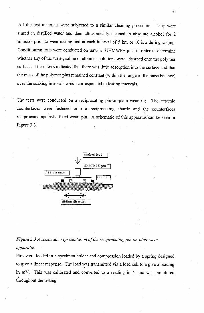
51
All the test materials were subjected to a similar cleaning procedure. They were
rinsed in distilled water and then ultrasonically cleaned in absolute alcohol for 2
minutes prior to wear testing and at each interval of 5 km or 10 km during testing.
Conditioning tests were conducted on unworn UHMWPE pins in order to determine
whether any of the water, saline or albumen solutions were adsorbed onto the polymer
surface. These tests indicated that there was little adsorption into the surface and that
the mass of the polymer pins remained constant (within the range of the mass balance)
over the soaking intervals which corresponded to testing intervals.
The tests were conducted on a reciprocating pin-on-plate wear rig. The ceramic
counterfaces were fastened onto a reciprocating shuttle and the counterfaces
reciprocated against a fixed wear pm. A schematic of this apparatus· can be seen in
Figure 3.3.
japplied load I
+~~ JUHMWPE pin
< > Jsliding direction
Figure 3.3 A schematic representation of the reciprocating pin-on-plate wear
apparatus.
Pins were loaded in a specimen holder and compression loaded by a spring designed
to give a linear response. The load was transmitted via a load cell to a give a reading
in m V .· This was calibrated and converted to a reading in N and was monitored a
throughout the testing ..
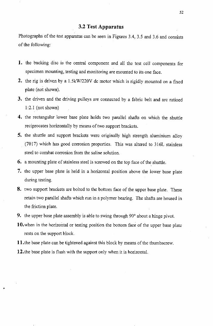
52
3.2 Test Apparatus
Photographs of the test apparatus can be seen in Figures 3.4, 3.5 and 3.6 and consists
of the following:
1. the backing disc is the central component and all the test cell components for
specimen mounting, testing and monitoring are mounted to its one face.
2. the rig is driven by a 1.5kW/220V de motor which is rigidly mounted on a fixed
plate (not shown).
3. the driven and the driving pulleys are connected by a fabric belt and are ratioed
1 :2.1 (not shown)
4. the rectangular lower base plate holds two parallel shafts on which the shuttle
reciprocates horizontally by means of two support brackets.
5. the shuttle and support brackets were originally high strength aluminium alloy
(7017) which has good corrosion properties. This was altered to 316L stainless
steel to combat corrosion from the saline solution.
6. a mounting plate of stainless steel is screwed on the top face of the shuttle.
7. the upper base plate is held in a horizontal position above the lower base plate
during testing.
8. two support brackets are bolted to the bottom face of the upper base plate. These
retain two parallel shafts which run in a polymer bearing. The shafts are housed in
the friction plate.
9. the upper base plate assembly is able to swing through 90° about a hinge pivot.
10. when in the horizontal or testing position the bottom face of the upper base plate
rests on the support block.
11.the base plate can be tightened against this block by means of the thumbscrew.
12.the base plate is flush with the support only when it is horizontal.
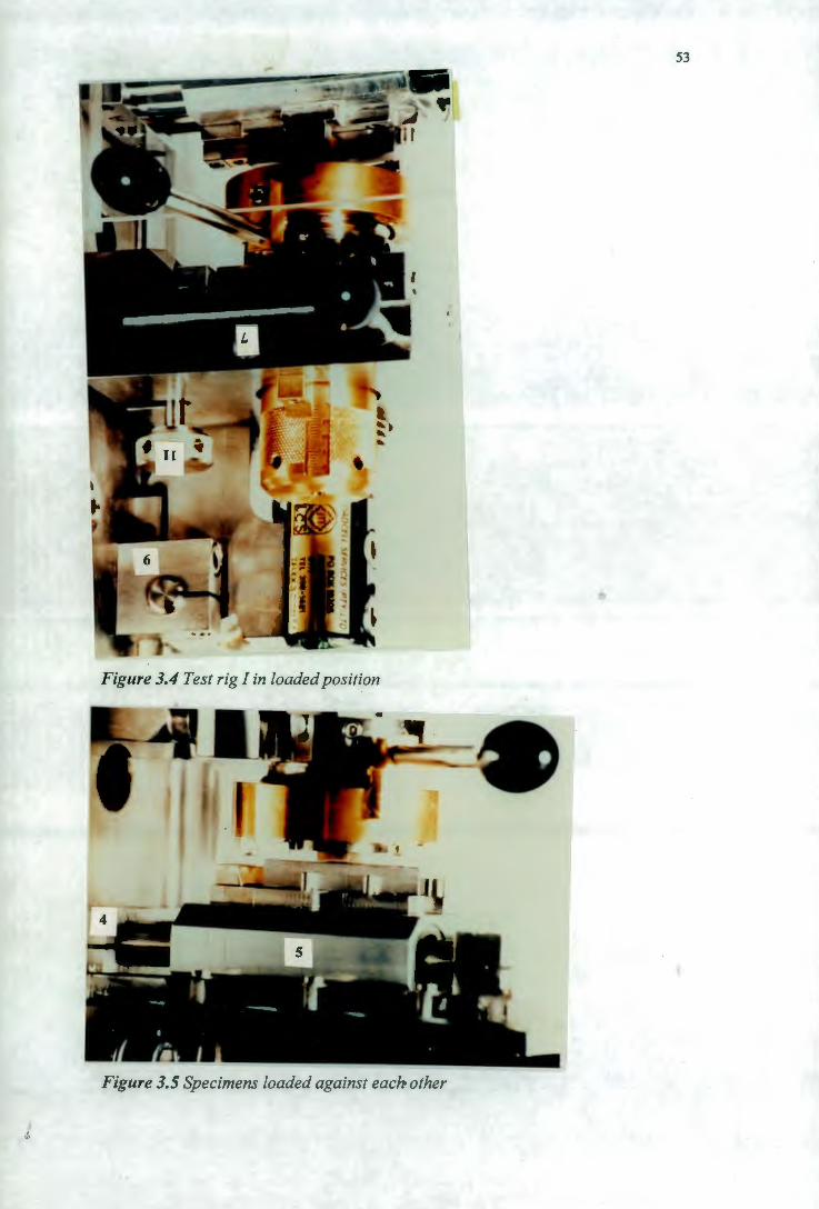
I I
Figure 3.4 Test rig I in loaded position
Figure 3.5 Specimens loaded against each other
53
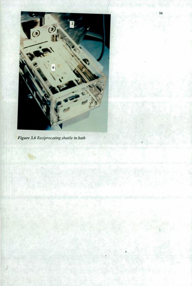
54
Figure 3. 6 Reciprocating shuttle in bath
55
3.2.1. Specimen Location
• the stationary specimen is held in position by a chuck consisting of two phosphor
bronze jaws, one fixed, the other adjustable.
• the reciprocating specimen is placed on the flat surface of the specimen mounting
plate.
• the long axis of the specimen mounting plate is positioned m line with the
reciprocating axis by means of three locating pins.
• tightening the wedge blocks forces the specimen against the pins.
• the specimen holder fits into the load assembly housing.
• two diametrically opposed slots are machined along the outer face of the holder
allowing it to fit over the two hold fingers as it is inserted.
• rotation of the specimen in the housing is prevented by tvvo holes of different
diameters. These couple up with two matching pins protruding from the plunger.
This allows axial movement but prevents rotation.
3.2.2 The Loading Mechanism
• loading of the specimen is achieved by a compression load spring designed to give
a linear response of 0 - 1 OON.
• the spring force is adjusted by turning the screw cap which has linear graduations
of SN on its outer face.
• a needle roller bearing is fitted to the load plunger to prevent the spring from
rotating while it is compressed.
3.2.3 The Coolant Bath
• a perspex enclosure is fitted to the lower base plate. This consists of three sides
and an open end with a small perspex cover to prevent fluid from splashing out of
the bath. The volume of the coolant bath was 250 mm3.
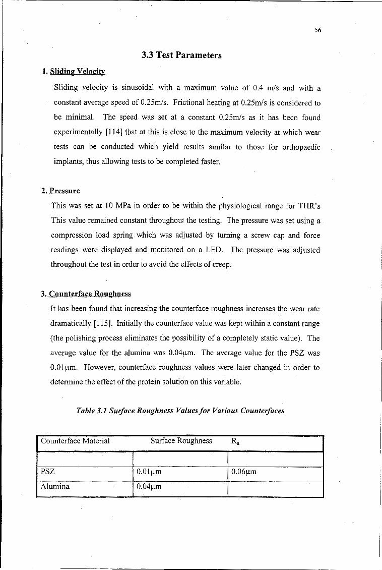
56
3.3 Test Parameters
1. Sliding Velocity
Sliding velocity is sinusoidal with a maximum value of 0.4 mis and with a
constant average speed of 0.25m/s. Frictional heating at 0.25m/s is considered to
be minimal. The speed was set at a constant 0.25m/s as it has been found
experimentally [114] that at this is close to the maximum velocity at which wear
tests can be conducted which yield results similar to those for orthopaedic
implants, thus allowing tests to be completed faster.
2. Pressure
This was set at 10 MP a in order to be within the physiological range for THR' s
This value remained constant throughout the testing. The pressure was set using a
compression load spring which was adjusted by turning a screw cap and force
readings were displayed and monitored on a LED. The pressure was adjusted
throughout the test in order to avoid the effects of creep.
3. Counterface Roughness
It has been found that increasing the counterface roughness increases the wear rate
dramatically [115]. Initially the counterface value was kept within a constant range
(the polishing process eliminates the possibility of a completely static value). The
average value for the alumina was 0.04µm. The average value for the PSZ was
O.Olµm. However, counterface roughness values were later changed in order to
determine the effect of the protein solution on this variable.
Table 3.1 Surface Roughness Values for Various Counterfaces
Counterface Material Surface Roughness Ra
PSZ O.Olµm 0.06µm
Alumina 0.04µm
57
4. Lubricant
Several lubricants were used in order to determine the effects of the addition of a
protein into the lubricant. It has been contended in the past that the proteins in
synovial fluid affect the wear process [118]. For this reason two different protein
solutions were used and distilled water and saline solution used as controls. Firstly
synovial fluid was used. Human synovial fluid was obtained from patients
undergoing knee replacement operations for osteoarthritis. Synovial fluid
produced in reaction to this joint disease is similar in composition to healthy fluid
and is produced in larger quantities than those found in healthy joints. The
synovial fluid had to be diluted because of its scarcity. Fluid had to be changed
every 5 km to avoid as far as possible any denaturing of the proteins. It was
chosen not to add antibiotics to extend the lifespan of the proteins as it is still not
clear as to how the antibiotics affect the wear process. The lubricant was drained
after 5 or 10 km tests. The synovial fluid was diluted with physiological saline.
The saline solution used had the following composition
• 9g sodium chloride (NaCl)/1000 ml
• 154mmol sodium ion
• 154mmol chloride ion
• pH approximately 5.5
• sterile and pyrogen free
This was chosen because it is known to be stable in the physiological environment
and because some proteins are only soluble in a saline environment.
Various attempts were made to ensure sufficient synovial fluid from either human or
bovine origin for testing purposes. This was unsuccessful and an alternative source of
protein lubrication was sought to replace that of the synovial fluid in the test
apparatus. As the investigation was concerned with the effect of a viscous protein
lubricant on sliding wear, albumen was selected. It was available in large quantities
and was observed to behave physically in a similar manner to synovial fluid. A single
synovial fluid test was conducted and then used as a basis for comparison for both the
albumen solutions and distilled water. e
58
Albumen contains the chief reserves of water and of certain nutrients (protein and
mineral salts) for the developing embryo [113].
Albumen contains the following proteins :
Table 3.1 Table of the Proteins found in Albumen [112}
Protein Percentage of total
Ovalbumin 69.7%
l Ovomucoid 12.7%
Ovoconalbumin 9.0%
Ovoglobulin 6.7%
Lysozyme and ovomucin 1.9%
These proteins are made up of various proportions of amino acids (see appendix). The
elemental composition of some of these proteins as a percentage of dry weight is
shown as follows:
Table 3.2 The Elemental Composition of Some Proteins found in Albumen as a
Percentage of Dry Weight [114}
c H N s p
ovalbumin 52.8% 7.1% 15.5% 1.66% 0.12%
ovo- 52.5% 7.0% 16.6% 1.83% 0.00%
conalbumin
a- 49.0% 6.9% 13.1% 2.20% 0.0%
ovomucoid
lysozyme 48.7% 6.4% 18.6% 2.53% 0.0%
Ovalbumin is representative of glycoproteins with a low proportion of carbohydrate.
Ovalbumin has a molecular weight of about 45 000 and contains per molecule a single
prosthetic group consistip.g of 5 mannose residues, 3 glucosamine residues and 3
59
acetyl groups. The molecular weight of the prosthetic group is about 1440 so there is
3 .2g carbohydrate per 1 OOg ovalbumin [107].
The molecular weight of conalbumin is approximately 87 000. One alanine is
terminal. Conalbumin binds 2 atoms of ferric iron per molecule. Copper and zinc are
bound much less strongly. The binding of the ferric or cupric ions requires the
presence of HC03 - and the reaction is facilitated by small polybasic anions
complexing the metal. The interaction with the ferric ions sets free 3 and interaction
with the cupric ions sets free hydrogen ions [107].
Thus the following lubricants were used:
Lubricant Percentage protein Percentage saline soln
distilled water 0 0
saline solution 0 100
synovial fluid 5 95
albumen 5 95
albumen 10 90
albumen 15 85
5. Sliding Distance
Mass loss measurements were taken of the UHWMPE pins and surface roughness
(Ra) measurements were taken of the ceramic counterfaces at 5km intervals
corresponding to the change in lubricant over a variety of total sliding distances.
Friction measurements were also taken . Several sliding distances were selected.
These were dictated by several factors. Firstly there was sufficient synovial fluid
for one test to reach a sliding distance of 35km. Thus the albumen and distilled
water tests were run to 35km for the basis of comparison. Further tests were run to
50 and 100 km. In a prosthetic hip joint a sliding distance of 10 to 50 km a year is
covered [119] and these results were taken as an indication of the extent of wear
that one could expect over that period of time.
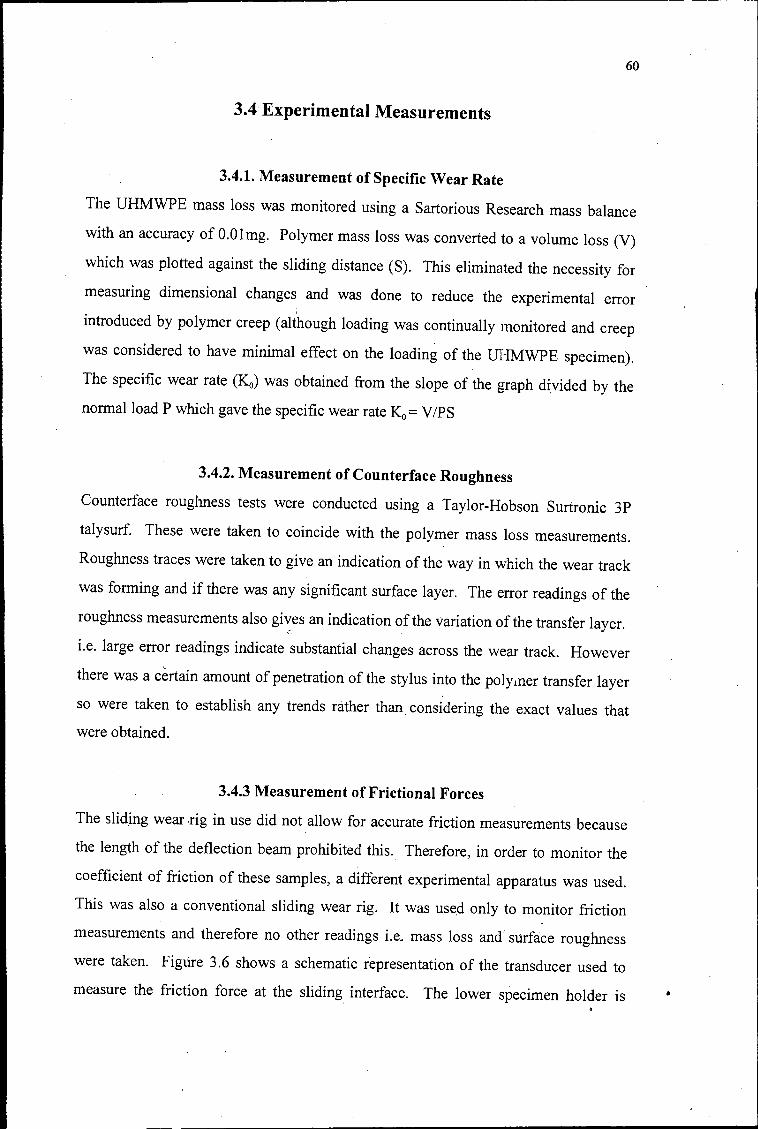
60
3.4 Experimental Measurements
3.4.1. Measurement of Specific Wear Rate
The UHMWPE mass loss was monitored using a Sartorious Research mass balance
with an accuracy of O.Olmg. Polymer mass loss was converted to a volume loss (V)
which was plotted against the sliding distance (S). This eliminated the necessity for
measuring dimensional changes and was done to reduce the experimental error '
introduced by polymer creep (although loading was continually monitored and creep
was considered to have minimal effect on the loading of the UHMWPE specimen).
The specific wear rate (Ko) was obtained from the slope of the graph divided by the
normal load P.which gave the specific wear rate Ko= VIPS
3.4.2. Measurement of Counterface Roughness
Counterface roughness tests were conducted using a Taylor-Hobson Surtronic 3P
talysurf. These were taken to coincide with the polymer mass loss measurements.
Roughness traces were taken to give an indication of the way in which the wear track
was forming and if there was any significant surface layer. The error readings of the
roughness measurements also gives an indication of the variation of the transfer layer. c
i.e. large error readings indicate substantial changes across the wear track. However
there was a certain amount of penetration of the stylus into the poly1ner transfer layer
so were taken to establish any trends rather than. considering the exact values that
were obtained.
3.4.3 Measurement of Frictional Forces
The sliding wear rig in use did not allow for accurate friction measurements because
the length of the deflection beam prohibited this.. Therefore, in order to monitor the
coefficient of friction of these samples, a different experimental apparatus was used.
· This was also a conventional sliding wear rig. It was use.d only to monitor friction
measurements and therefore no other readings i.e. mass loss and' surface roughness
were taken. Figure 3.6 shows a schematic representation of the transducer used to
measure the friction force at the sliding interface. The lower specimen holder is •
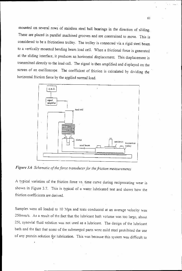
61
mounted on several rows of stainless steel ball bearings in the direction of sliding.
These are placed in parallel machined grooves and are constrained to move. This is
considered to be a frictionless trolley. The trolley is connected via a rigid steel beam
to a vertically mounted bending beam load cell. When a frictional force is generated
at the sliding interface, it produces an horizontal displacement. This displacement is
transmitted directly to the load cell. The signal is then amplified and d'.splayed on the
screen of an oscilloscope. The coefficient of friction is calculated by dividing the
horizontal friction force by the applied normal load.
signal amplifier
. load cell
D
Figure 3. 6 Schematic of the force transducer for the friction measurements
A typical variation of the friction force vs. time curve during reciprocating wear is
shown in Figure 3.7. This is typical of a water lubricated test and shows how the
friction coefficients are derived.
Samples were all loaded to 10 Mpa and tests conducetd at an average velocity was
250mm/s. As a result of the fact that the lubricant bath volume was too large, about
251, synovial fluid solution was not used as a lubricant. The design of the lubricant
bath and the fact that some of the submerged parts were mild steel prohibited the use
of any protein solution for lubrication. This was because this system was difficult to •
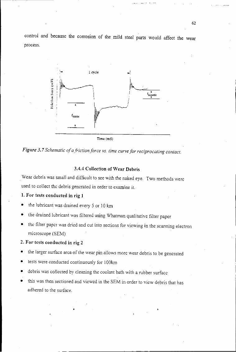
62
control and because the corrosion of the mild steel parts would affect the wear
process.
: ' . '- 1 cycle
Time (mS)
I ... ,
~l /\~~-I .I. I fkinetic
j ' I
Figure 3. 7 Schematic of a friction force vs. time curve for reciprocating contact.
3.4.4 Collection of Wear Debris
Wear debris was small and difficult to see with the naked eye. Two methods were
used to collect the debris generated in order to examine it.
1. For tests conducted in rig 1
• the lubricant was drained every 5 or 10 km
• the drained lubricant was filtered using Whatman qualitative filter paper
• the filter paper was dried and cut into sections for viewing in the scanning electron
microscope (SEM)
2. For tests conducted in rig 2
• the larger surface area of the wear pin allows more wear debris to be generated
• tests were conducted continuously for 1 OOkm
• debris was collected by cleaning the coolant bath with a rubber surface
• this vvas then sectioned and viewed in the SEM in order to view debris that has
adhered to the surface.
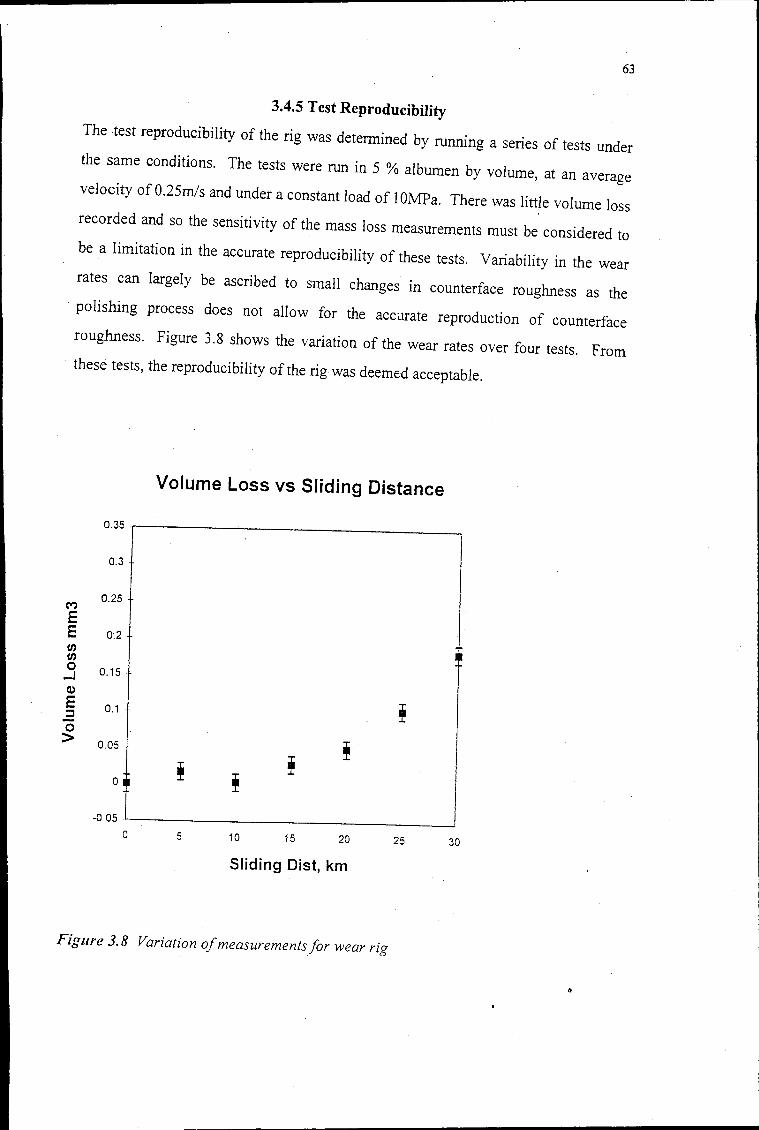
63
3.4.5 Test Reproducibility
The test reproducibility of the rig was detennined by running a series of tests under
the same conditions. The tests were run in 5 % albumen by volume, at an average
velocity of 0.25m!s and under a constant load of I OMPa. There was little volume loss
recorded and so the sensitivity of the mass loss measurements must be considered to
be a limitation in the accurate reproducibility of these tests. Variability in the wear
rates can largely be ascribed to small changes in counterface roughness as the
polishing process does not allow for the accurate reproduction of counterface
roughness. Figure 3.8 shows the variation of the wear rates over four tests. From
these tests, the reproducibility of the rig was deemed acceptable.
Volume Loss vs Sliding Distance
0.35
0.3
M 0.25
E E 0:2
"' "' 0 0.15 . ..J (1)
E 0.1 ! :::I 0 > 0.05 !
0
-0.05 .
0 5 10 15 20 25 30
Sliding Dist, km
Figure 3. 8 Variation of measurements/or wear rig
64
3.5 Polymer Characterisation
3.5.1 Scanning Electron Microscopy
After the completion of a test the polymer pins and ceramic counterfaces were
ultrasonically cleaned in alcohol and then in isopropanol. The pins and counterfaces
were .then gold-palladium coated using a Polaron E5100 Series II 'Cool' Sputter
Coater. This was done to ensure that the specimen was conducting and that it did not
charge in the beam. Filter paper and rubber sections were also gold-palladium coated.
Samples were then mounted on aluminium stubs using carbon <lag. Samples were
then viewed in the Cambridge S200 Stereoscan scanning electron microscope (SEM).
An accelerating voltage of 15 or 20 kV was used. These were chosen as the best
micrographs could be obtained at these accelerating voltages. In addition to this, the
UHMWPE is beam sensitive and tended to crack when exposed to beams of high
accelerating voltages.
3.5.2 Energy Dispersive Spectroscopy (EDS)
It was not possible to use EDS to obtain a semi-quantitative composition of the wear
debris or the transfer layers on the ceramic counterfaces. This is because carbon and
hydrogen are the principal elements in both the polymer and the proteins and these
elements cannot be analysed using the EDS system. EDS was used to check for
foreign particles such as rust that may have been generated during testing. The Tracor
Northern TN 5400 energy dispersive X-ray microanalyser attached to the SEM was
used for this purpose.
3.5.3 Optical Microscopy
A Reichart projection microscope was used to obtain images of microtomed
UHMWPE films under polarised light. Polymer chains are highly anisotropic with
respect to their dimensions and thus pollarisability parallel to the chain will differ
from that perpendicular to it. The refractive index of the light wave with an electric
vector parallel to the chain will therefore differ from that of a wave with its electric
65
vector perpendicular to it. That is to say that polymer chains are intrinsically
birefringent and orientation effects are manifested as a visible birefringence.
3.5.4 Scratch Tests
It appeared that the polymer surface was altering as a result of sliding wear. In order
to investigate how the surface of the worn UHMWPE pins differed to that of the
unworn pins, scratch tests were conducted on worn and unworn surfaces. The
UHMWPE surfaces were scratched with a Rockwell C diamond indentor under a load
of SON [119]. These were then viewed optically and in the electron microscope.
66
3.6 Counterface Characterisation
3.6.1 Optical Microscopy
Optical photographs of the zirconia and alumina surfaces were taken at varying stages
of the sliding wear process. For this purpose a Nikon Optishot optical microscope
was used.
3.6.2 Scanning Electron Microscopy (SEM)
Zirconia and alumina worn ceramic surfaces were Au-Pd coated. Samples were then
mounted on aluminium stubs using carbon <lag. Samples were then viewed in the
Cambridge S200 Stereoscan scanning electron microscope. An accelerating voltage
of 15 or 20 kV was used. The material visible on the counterface was considered to
be UHWMPE and because of its beam sensitivity relatively low accelerating voltages
were chosen.
3.6.3 X-Ray Photoelectron Spectroscopy (XPS)
As the nature of the transfer layer was unclear from the micro graphs, XPS was used in
an attempt to analyse whether the protein solution was adsorbing onto the counterface
surfaces. A VG Esaclab MkII was used. The samples were irradiated with X-Rays of
15k V and the binding energy of the emitted photoelectrons were determined in a
hemispherical analyser. A semi-quantitative analysis of the surface can be calculated
within a detection limit of O.lat%.
3.6.4 Secondary Ion Mass Spectroscopy (SIMS)
SIMS was used in order to verify the results obtained for the XPS. A VG Escalab
MkII fitted with a MIG 100 SIMS attachment was used. The atomic mass of
sputtered ions is determined in a mass quadropole. The analysis depth is 10 A and the
detection limits vary from ppm to ppb
3.6.5 Auger Electron Spectroscopy (AES)
As only one test was run using synovial fluid, the sample on which the XPS and
SIMS were conducted was Au-Pd coated for SEM viewing. Thus it was not clear if
I
67
the SIMS analysis was being conducted below the coating layer. AES was used to
determine whether the results that were obtained for the XPS and SIMS analyses were
a depiction of the transfer layer below the Au-Pd coating or that of the Au-Pd coating
itself. A Phi 595. Scanning Electron Microbe was used and samples were irradiated at
3kV. The Auger electrons that are emitted from the surface are measured in a
cylindrical mirror analyser. Semi-:quantitative results can be calculated· from the peak
areas within a detection limit of 0.1 %
•
68
3. 7 Wear Debris Analysis
3. 7.1 Scanning Electron Microscopy(SEM)
Filtered lubricating solution and collected debris was too fine to be viewed optically.
Debris was collected on rubber surfaces or on filter paper. These were Au-Pd coated
using a Polaron E1500 Series II "Cool" Sputter Coater. The debris was photographed
and size fraction analyses were conducted.
3. 7.2 Energy Dispersive Spectroscopy (EDS)
EDS analyses were conducted on the debris to determine whether it was UHMWPE.
If scans for the debris particles were similar to. the material adjacent to them, the
debris was assumed to be UHMWPE. The Tracor Northern TN 5400 energy
dispersive X-ray microanalyser attached to the SEM wa.s used for this purpose.
69
Chapter 4
RESULTS
4.1 Introduction
This chapter presents an analysis of the wear behaviour of UHMWPE when sliding
against a ceramic counterface in various lubricating media. The experimental results
are divided into several sections as follows:
(1) Wear
(2) Friction
(3) Polymer Behaviour
(4) The Nature of the Wear Scar
(5) The Nature of the Wear Debris
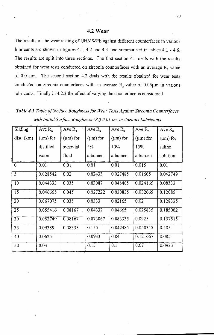
70
4.2 Wear
The results of the wear testing of UHMWPE against different counterfaces in various
lubricants are shown in figures 4.1, 4.2 and 4.3. and summarised in tables 4.1 - 4.6.
The results are split into three sections. The ·first section 4.1 deals with the results
obtained for wear tests conducted on zirconia counterfaces with an average Ra value
of O.Olµm. The second section 4.2 deals with the results obtained for wear tests
conducted on zirconia counterfaces with an average Ra value of 0.06µm in various
lubricants. Finally in 4.2.3 the effect of varying the counterface is considered.
Table 4.1 Table of Surface Roughness for Wear Tests Against Zirconia Counter/aces
with Initial Surface Roughness (R;) O.Olµm in Various Lubricants
Sliding Ave Ra Ave Ra ;
Ave Ra Ave Ra Ave Ra Ave Ra
dist. (km) (µm) for (µm) for (µm) for (µm) for (µm) for (µm) for
distilled synovial 5% 10% 15% saline
water fluid albumen albumen albumen solution
0 0.01 0.01 0.01 0.01 0.015 0.01
5 0.028542 0.02 0.02433 0.027485 0.01665 0.042749
10 0.044333 0.035 0.03087 0.048465 0.024165 0.08333
15 0.046665 0.045 0.027222 0.030835 0.032665 0.12085
20 0.067075 0.035 0.0333 0.02165 0.02 0.128335
25 0.055416 0.08167 0.04332 0.04665 0.025835 0.185002
30 0.053749 0.08167 0.073867 0.083335 0.0925 0.197515
35 0.09389 0.08333 0.155 0.042485 0.058315 0.505
40 0.0625 0.0933 0.04 0.121667 0.085
50 0.03 0.15 0.1 0.07 0.0933
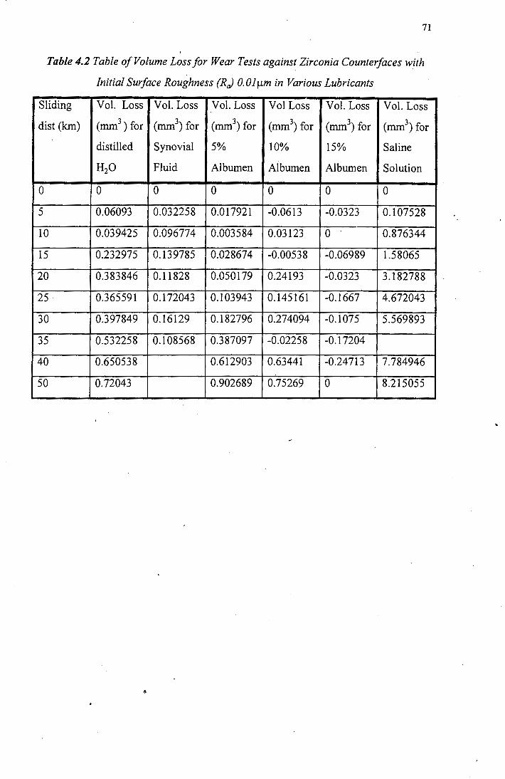
71
, Table 4.2 Table of Volume Loss for Wear Tests against Zirconia Counter/aces with
Initial Surface Roughness (R) O.Olµm in Various Lubricants
Sliding Vol. Loss Vol. Loss Vol. Loss Vol Loss Vol. Loss Vol. Loss
dist (km) (mm3) for (mm3
) for (mm3) for (mm3
) for (mm3) for 3 (mm) for
distilled Synovial 5% 10% 15% Saline
H20 Fluid Albumen Albumen Albumen Solution
0 0 0 0 0 0 0
5 0.06093 0.032258 0.017921 -0.0613 -0.0323 0.107528
IO 0.039425 0.096774 0.003584 0.03123 0 0.876344
15 0.232975 0.139785 0.028674 -0.00538 -0.06989 1.58065
20 0.383846 0.11828 0.050179 0.24193 -0.0323 3.182788
25 0.365591 0.172043 0.103943 0.145161 -0.1667 4.672043
30 0.397849 0.16129 0.182796 0.274094 -0.1075 5.569893
35 0.532258 0.108568 0.387097 -0.02258 -0.17204
40 0.650538 0.612903 0.63441 -0.24713 7.784946
50 0.72043 0.902689 0.75269 0 8.215055
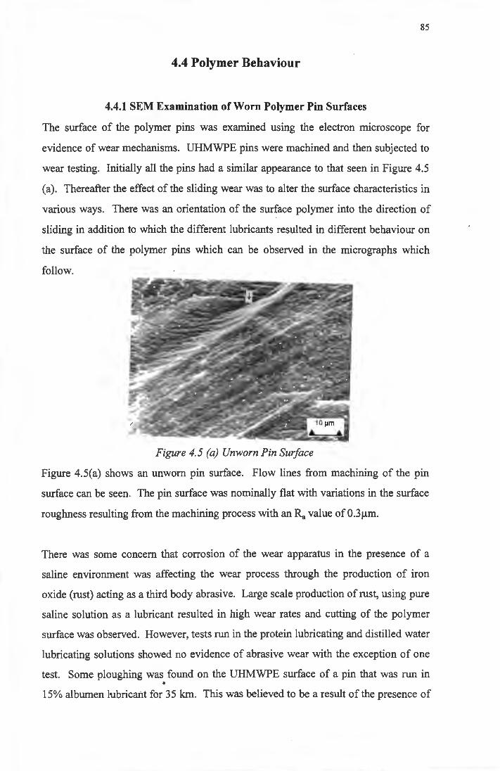
85
4.4 Polymer Behaviour
4.4.1 SEM Examination of Worn Polymer Pin Surfaces
The surface of the polymer pins was examined using the electron microscope for
evidence of wear mechanisms. UHMWPE pins were machined and then subjected to
wear testing. Initially all the pins had a similar appearance to that seen in Figure 4.5
(a). Thereafter the effect of the sliding wear was to alter the surface characteristics in
various ways. There was an orientation of the surface polymer into the direction of
sliding in addition to which the different lubricants resulted in different behaviour on
the surface of the polymer pins which can be observed in the micrographs which
follow.
Figure 4.5 (a) Unworn Pin Surface
Figure 4.5(a) shows an unworn pin surface. Flow lines from machining of the pin
surface can be seen. The pin surface was nominally flat with variations in the surface
roughness resulting from the machining process with an Ra value of 0.3µm.
There was some concern that corrosion of the wear apparatus in the presence of a
saline environment was affecting the wear process through the production of iron
oxide (rust) acting as a third body abrasive. Large scale production of rust, using pure
saline solution as a lubricant resulted in high wear rates and cutting of the polymer
surface was observed. However, tests run in the protein lubricating and distilled water
lubricating solutions showed no evidence of abrasive wear with the exception of one
test. Some ploughing was found on the UHMWPE surface of a pin that was run in •
15% albumen lubricant for 35 km. This was believed to be a result of the presence of
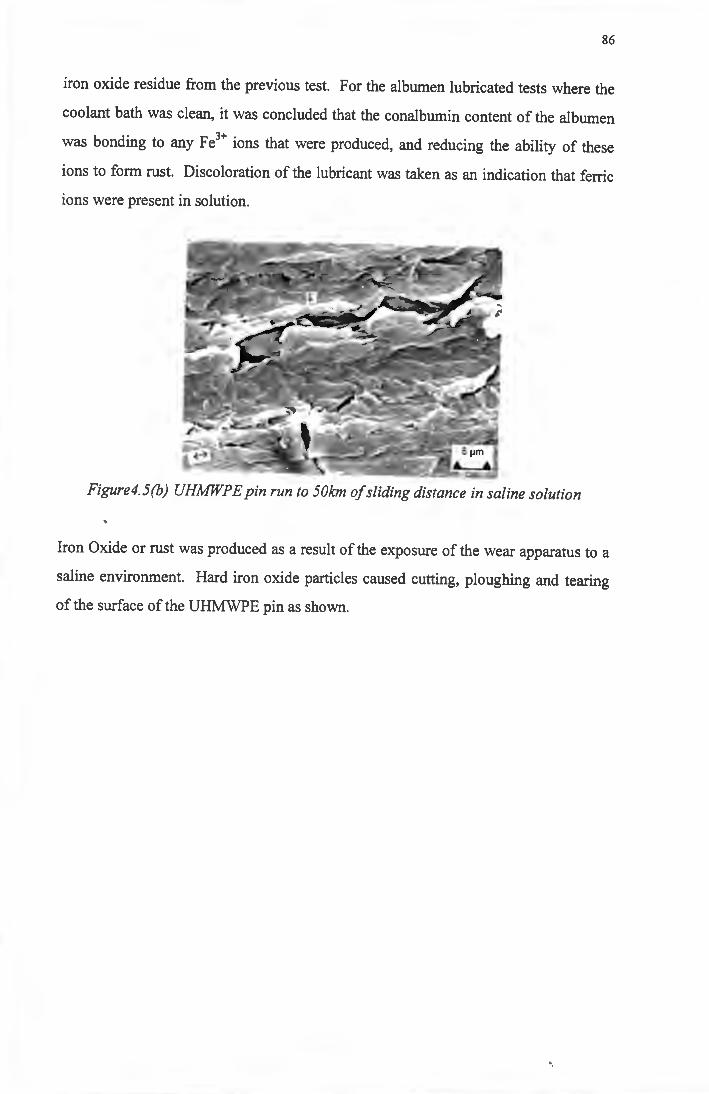
86
iron oxide residue from the previous test. For the albumen lubricated tests where the
coolant bath was clean, it was concluded that the conalbumin content of the albumen
was bonding to any Fe3+ ions that were produced, and reducing the ability of these
ions to form rust. Discoloration of the lubricant was taken as an indication that ferric
ions were present in solution.
Figure4.5(b) UHMWPE pin run to 50km of sliding distance in saline solution
Iron Oxide or rust was produced as a result of the exposure of the wear apparatus to a
saline environment. Hard iron oxide particles caused cutting, ploughing and tearing
of the surface of the UHMWPE pin as show.i.
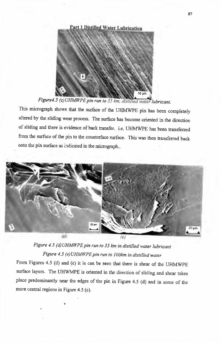
87
-
Figure4.5 (c)UHMWPE pin run to 35 km, disti
This micrograph shows that the surface of the UHMWPE pin has been completely
altered by the sliding wear process. The surface has become oriented in the direction
of sliding and there is evidence of back transfer. i.e. UHMWPE has been transferred
from the surface of the pin to the counterface surface. This was then transferred back
onto the pin surface as i_1dicated in the micrograph ..
Figure 4.5 (d)UHMWPEpin run to 35 km in distilled water lubricant
Figure 4. 5 (e) UHMWP E pin run to I OOkm in distilled water
From Figures 4.5 (d) and (e) it is can be seen that there is shear of the UHMWPE
surface layers. The UHWMPE is oriented in the direction of sliding and shear takes
place predominantly near the edges of the pin in Figure 4.5 (d) and in some of the
more central regions in Figure 4.5 (e) .
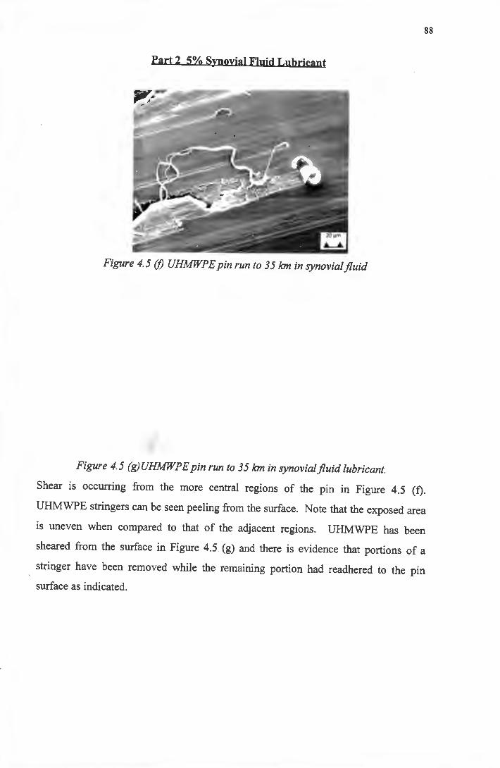
88
Part 2 5% Synovial Fluid Lubricant
Figure 4.5 (/) UHMWPEpin run to 35 km in synovialfluid
Figure 4.5 (g)UHMWPEpin run to 35 km in synovialfluid lubricant.
Shear is occurring from the more central regions of the p·n in Figure 4.5 (f).
UHMWPE stringers can be seen peeling from the surface. Note that the exposed area
is uneven when compared to that of the adjacent regions. UHMWPE has been
sheared from the surface in Figure 4.5 (g) and there is evidence that portions of a
stringer have been removed while the remaining portion had readhered to the pin
surface as indicated.
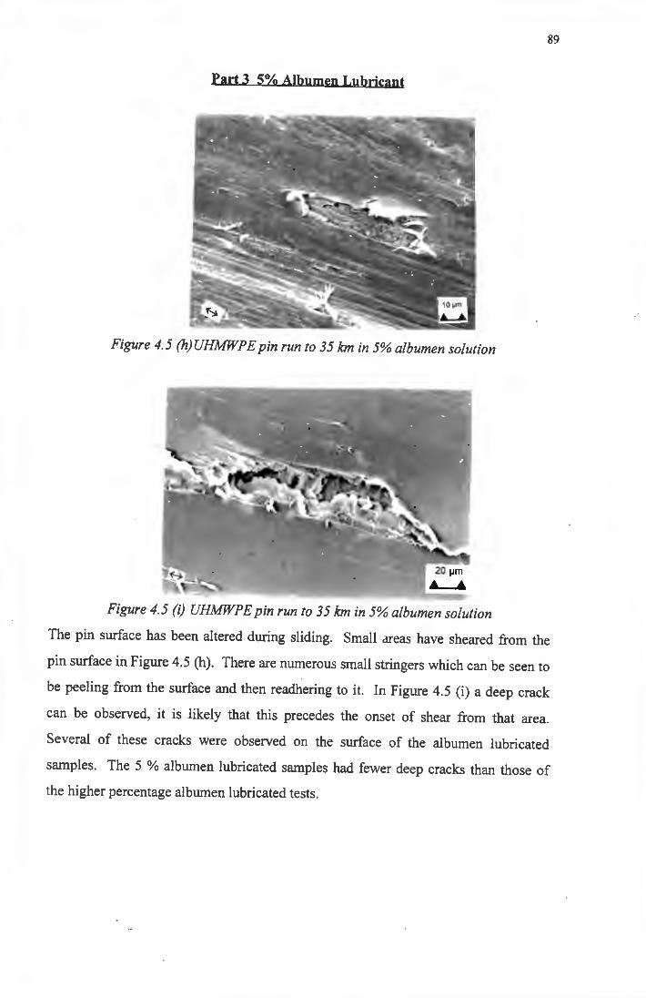
89
Part 3 5% Albumen Lubricant
Figure 4.5 (h) UHMWPE pin run to 35 km in 5% albumen solution
Figure 4.5 (i) UHMWPE pin run to 35 km in 5% albumen solution
The pin surface has been altered during sliding. Small areas have sheared from the
pin surface in Figure 4.5 (h). There are numerous small stringers which can be seen to
be peeling from the surface and then readhering to it. In Figure 4.5 (i) a deep crack
can be observed, it is likely that this precedes the onset of shear from that area.
Several of these cracks were observed on the surface of the albumen lubricated
samples. The 5 % albumen lubricated samples had fewer deep cracks than those of
the higher percentage albumen lubricated tests.
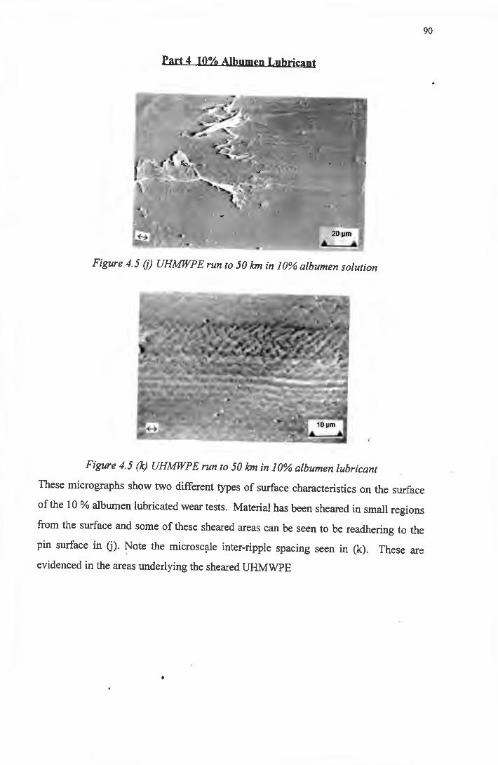
90
Part 4 10% Albumen Lubricant
Figure 4.5 (j) UHMWPE run to 50 km in 10% albumen solution
Figure 4.5 (k) UHMWPE run to 50 km in 10% albumen lubricant
These micrographs show two different types of surface characteristics on the surface
of the 10 % albumen lubricated wear tests. Material has been sheared in small regions
from the surface and some of these sheared areas can be seen to be readhering to the
pin surface in G). Note the microscale inter-ripple spacing seen in (k). These are
evidenced in the areas underlying the sheared UHMWPE
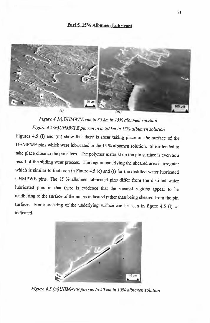
91
Part 5 15% Albumen Lubricant
Figure 4.5(/)UHMWPE run to 35kmin15% albumen solution
Figure 4. 5 (m) UHMWP E pin run in to 5 0 km in 15% albumen solution
Figures 4.5 (1) and (m) show that there is shear taking place on the surface of the
UHMPWE pins which were lubricated in the 15 % albumen solution. Shear tended to
take place close to the pin edges. The polymer material on the pin surface is even as a
result of the sliding wear process. The region underlying the sheared area is irregular
which is similar to that seen in Figure 4.5 (e) and (f) for the distilled water lubricated
UHMPWE pins. The 15 % albumen lubricated pins differ from the distilled water
lubricated pins in that there is evidence that the sheared regions appear to be
readhering to the surface of the pin as indicated rather than being sheared from the pin
surface. Some cracking of the underlying surface can be seen in figure 4.5 (1) as
indicated.
Figure 4. 5 (m) UHMWP E pin run to 5 0 km in 15% albumen solution
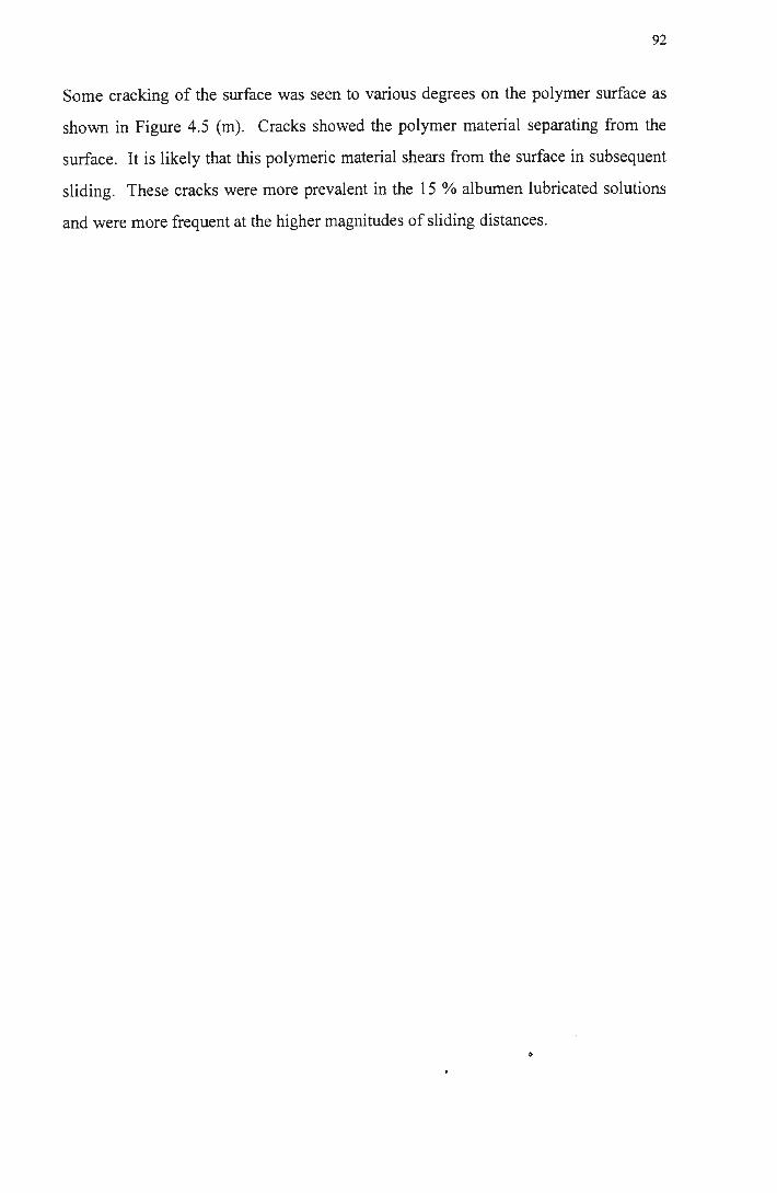
92
Some cracking of the surface was seen to various degrees on the polymer surface as
shown in Figure 4.5 (m). Cracks showed the polymer material separating from the
surface. It is likely that this polymeric material shears from the surface in subsequent
sliding. These cracks were more prevalent in the 15 % albumen lubricated solutions
and were more frequent at the higher magnitudes of sliding distances.
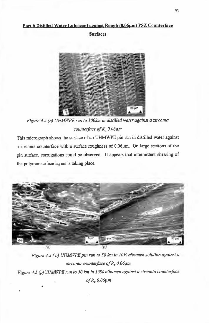
Part 6 Distilled Water Lubricant against Rough (0.06µm) PSZ Counterface
Surfaces
Figure 4. 5 (n) UHMWP E run to 1 OOkm in distilled water against a zirconia
counter/ace of Ra 0. 06µm
93
This micrograph shows the surface of an UHMWPE pin run in distilled water against
a zirconia counterface with a surface roughness of 0.06µm. On large sections of the
pin surface, corrugations could be observed. It appears that intermittent shearing of
the polymer surface layers is taking place.
Figure 4.5 ( o) UHMWPE pin run to 50 km in 10% albumen solution against a
zirconia counter/ace of Ra 0. 06µm
Figure 4. 5 (p) UHMWP E run to 50 km in 15% albumen against a zirconia counter/ace
of Ra 0.06µm
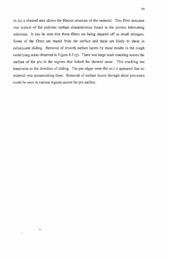
94
In ( o) a sheared area shows the fibrous structure of the material. This fibre structure
was typical of the polymer surface characteristics found in the protein lubricating
solutions. It can be seen that these fibres are being sheared off as small stringers.
Some of the fibres are teased from the surface and these are likely to shear in
subsequent sliding. Removal of smooth surface layers by shear results in the rough
underlying areas observed in Figure 4.5 (p ). There was large scale cracking across the
surface of the pin in the regions that linked the sheared areas. This cracking ran
transverse to the direction of sliding. The pin edges were flat ar~d it appeared that no
material was accumulating there. Removal of surface layers through shear processes
could be seen in various regions across the pin surface.
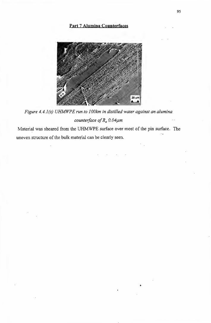
Part 7 Alumina Counterfaces
Figure 4. 4.1 (s) UHMWP E run to I OOkm in distilled water against an alumina
counter/ace of Ra 0. 04µm
95
Material was sheared from the UHMWPE surface over most of the pin surface. The
uneven structure of the bulk material can be clearly seen.
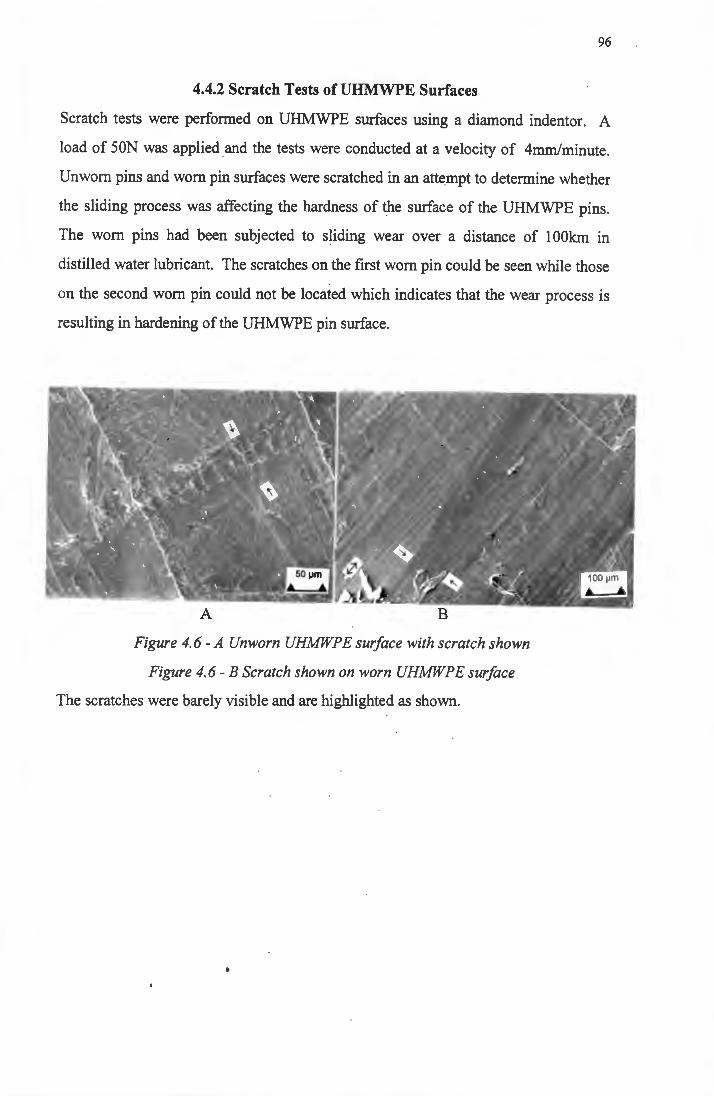
96
4.4.2 Scratch Tests of UHMWPE Surfaces
Scratch tests were performed on UHMWPE surfaces using a diamond indentor. A
load of SON was applied and the tests were conducted at a velocity of 4mm/minute.
Unworn pins and worn pin surfaces were scratched in an attempt to determine whether
the sliding process was affecting the hardness of the surface of the UHMWPE pins.
The worn pins had been subjected to sliding wear over a distance of 1 OOkm in
distilled water lubricant. The scratches on the first worn pin could be seen while those
on the second worn pin could not be located which indicates that the wear process is
resulting in hardening of the UHMWPE pin surface.
Figure 4. 6 - A Unworn UHMWP E surface with scratch shown
Figure 4. 6 - B Scratch shown on worn UHMWP E surface
The scratches were barely visible and are highlighted as shown.
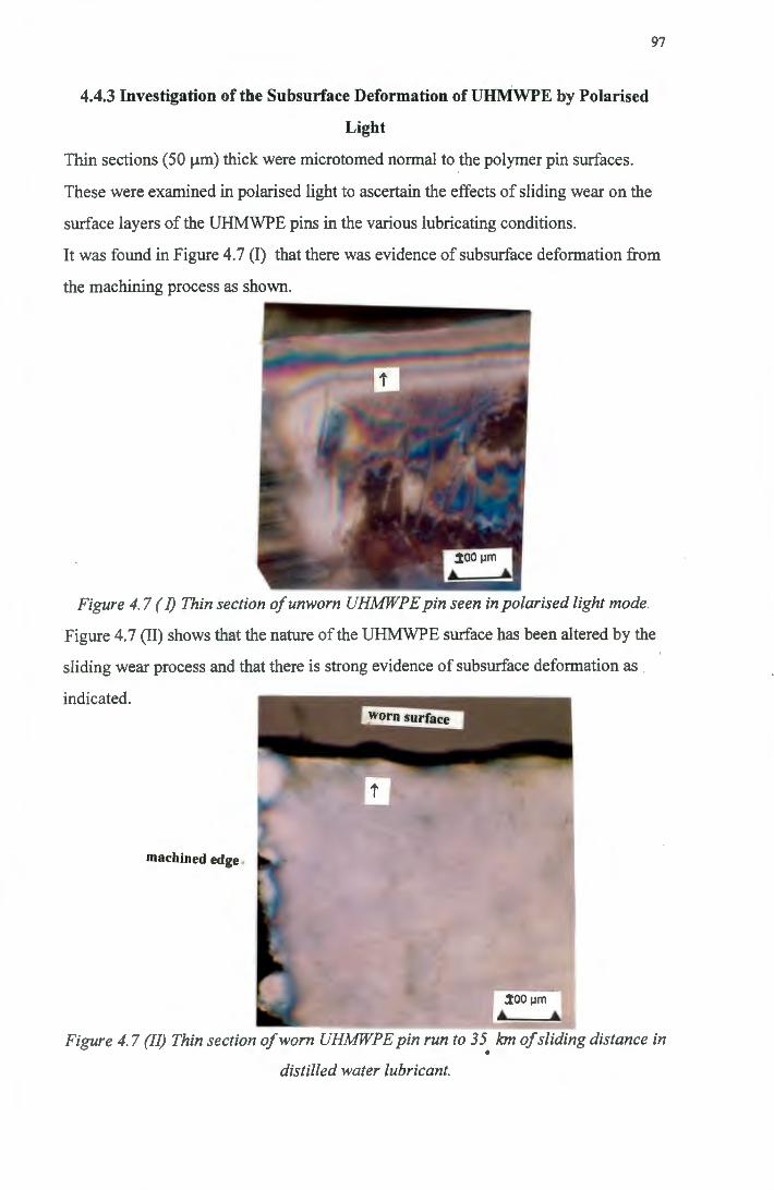
4.4.3 Investigation of the Subsurface Deformation of UHMWPE by Polarised
Light
Thin sections (50 µm) thick were microtomed normal to the polymer pin surfaces.
These were examined in polarised light to ascertain the effects of sliding wear on the
surface layers of the UHMWPE pins in the various lubricating conditions.
97
It was found in Figure 4.7 (I) that there was evidence of subsurface deformation from
the machining process as shown.
Figure 4. 7 (I) Thin section of unworn UHMWP E pin seen in polarised light mode.
Figure 4.7 (II) shows that the nature of the UHMWPE surface has been altered by the
sliding wear process and that there is strong evidence of subsurface deformation as
indicated.
machined edge .
:i;oo µm
• • Figure 4. 7 (JI) Thin section of worn UHMWPE pin run to 35 km of $liding distance in
• distilled water lubricant.
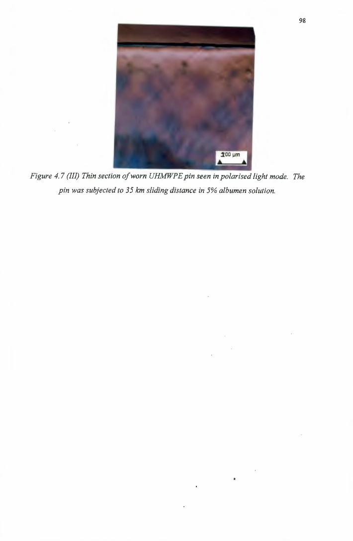
98
Figure 4. 7 (III) Thin section of worn UHMWP E pin seen in polarised light mode. The
pin was subjected to 35 km sliding distance in 5% albumen solution.
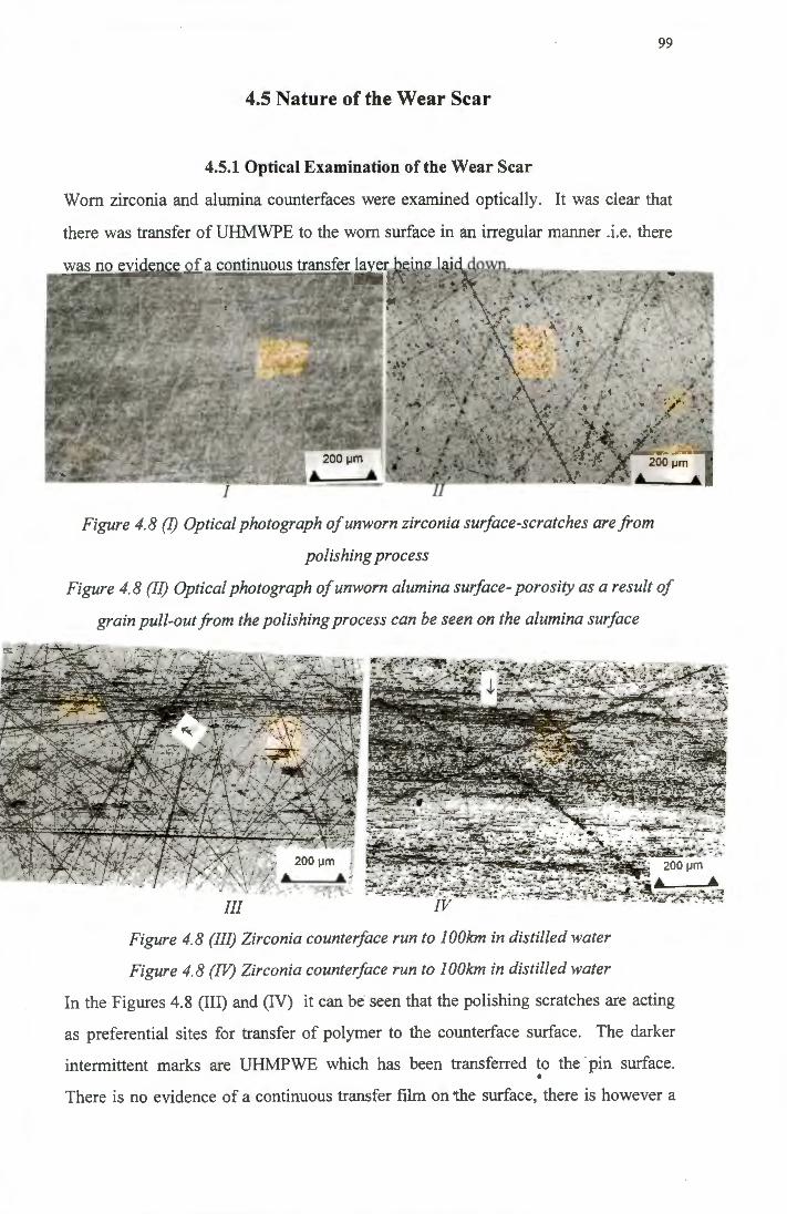
99
4.5 Nature of the Wear Scar
4.5.1 Optical Examination of the Wear Scar
Worn zirconia and alumina counterfaces were examined optically. It was clear that
there was transfer of UHMWPE to the worn surface in an irregular manner .i.e. there
Figure 4. 8 (I) Optical photograph of unworn zirconia surface-scratches are from
polishing process
Figure 4. 8 (II) Optical photograph of unworn alumina surface- porosity as a result of
grain pull-out from the polishing process can be seen on the alumina surface
Figure 4. 8 (III) Zirconia counter/ace run to 1 OOkm in distilled water
Figure 4. 8 (IV) Zirconia counter/ace run to 1 OOkm in distilled water
In the Figures 4.8 (III) and (IV) it can be seen that the polishing scratches are acting
as preferential sites for transfer of polymer to the counterface surface. The darker
intermittent marks are UHMPWE which has been transferred to the ·pin surface . •
There is no evidence of a continuous transfer film on the surface, there is however a
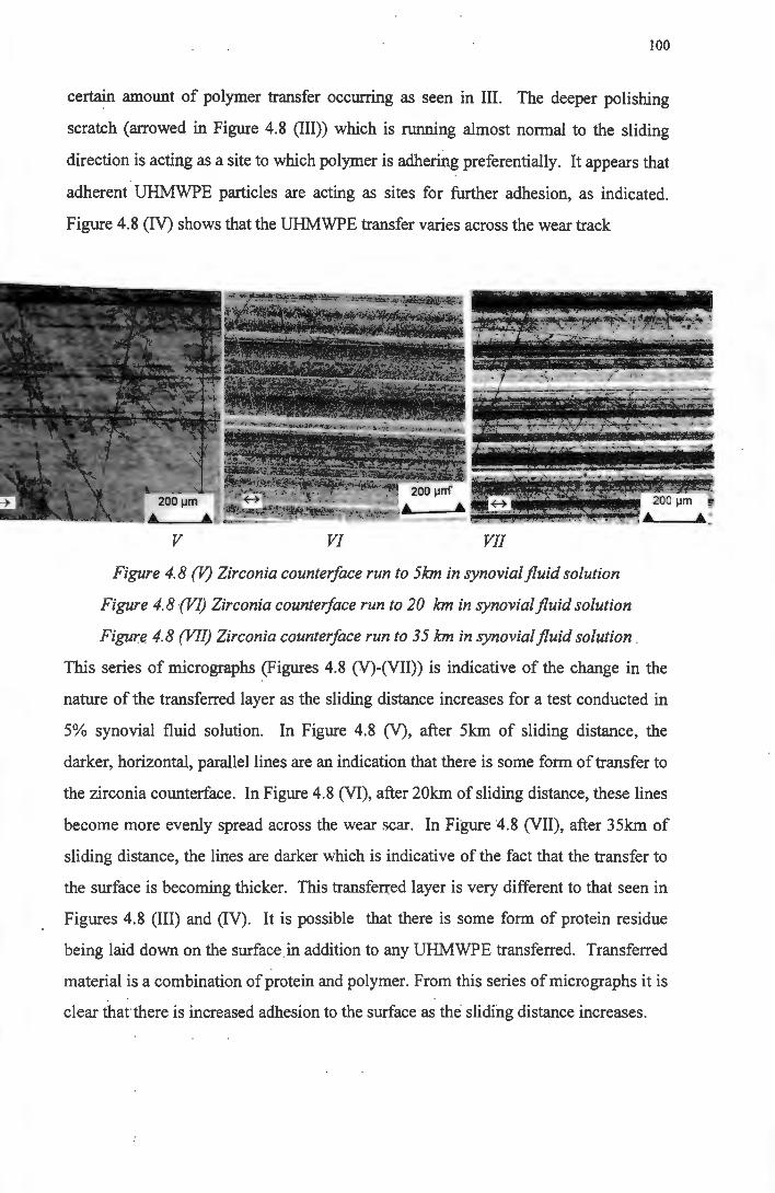
100
certain amount of polymer transfer occurring as seen in III. The deeper polishing
scratch (arrowed in Figure 4.8 (III)) which is running almost normal to the sliding
direction is acting as a site to which polymer is adhering preferentially. It appears that
adherent UHMWPE particles are acting as sites for further adhesion, as indicated.
Figure 4.8 (IV) shows that the UHMWPE transfer varies across the wear track
v VI VII
Figure 4.8 (V) Zirconia counter/ace run to 5km in synovialfluid solution
Figure 4.8 (VJ) Zirconia counter/ace run to 20 km in synovialfluid solution
Figure 4.8 (VII) Zirconia counter/ace run to 35 km in synovialfluid solution
This series of micrographs (Figures 4.8 (V)-(VII)) is indicative of the change in the
nature of the transferred layer as the sliding distance increases for a test conducted in
5% synovial fluid solution. In Figure 4.8 (V), after 5km of sliding distance, the
darker, horizontal, parallel lines are an indication that there is some form of transfer to
the zirconia counterface. In Figure 4.8 (VI), after 20km of sliding distance, these lines
become more evenly spread across the wear scar. In Figure 4.8 (VII), after 35km of
sliding distance, the lines are darker which is indicative of the fact that the transfer to
the surface is becoming thicker. This transferred layer is very different to that seen in
Figures 4.8 (III) and (IV). It is possible that there is some form of protein residue
being laid down on the surface in addition to any UHMWPE transferred. Transferred
material is a combination of protein and polymer. From this series of micro graphs it is
clear that there is increased adhesion to the surface as the sliding distance increases.
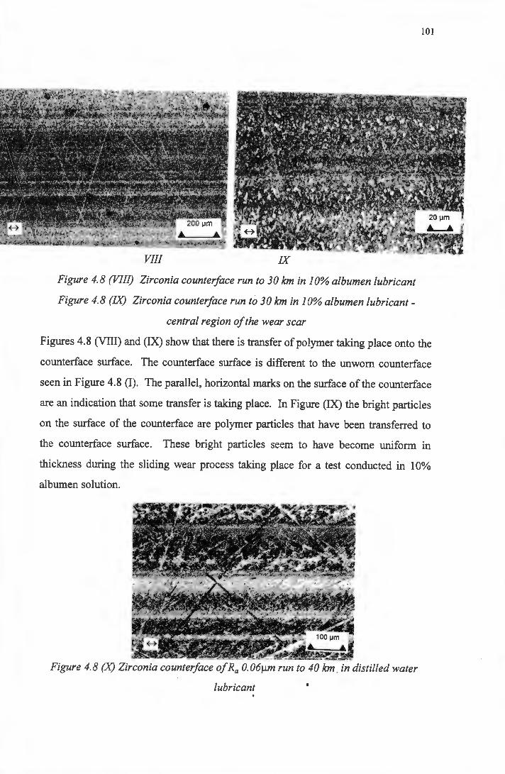
IX
Figure 4.8 (VIII) Zirconia counter/ace run to 30 km in 10% albumen lubricant
Figure 4.8 (IX) Zirconia counter/ace run to 30 km in 10% albumen lubricant-
central region of the wear scar
101
Figures 4.8 (VIII) and (IX) show that there is transfer of polymer taking place onto the
counterface surface. The counterface surface is different to the unworn counterface
seen in Figure 4.8 (I). The parallel, horizontal marks on the surface of the counterface
are an indication that some transfer is taking place. In Figure (IX) the bright particles
on the surface of the counterface are polymer particles that have been transferred to
the counterface surface. These bright particles seem to have become uniform in
thickness during the sliding wear process taking place for a test conducted in 10%
albumen solution.
Figure 4. 8 (X) Zirconia counter/ace of Ra 0. 06µm run to 40 km . in distilled water
lubricant
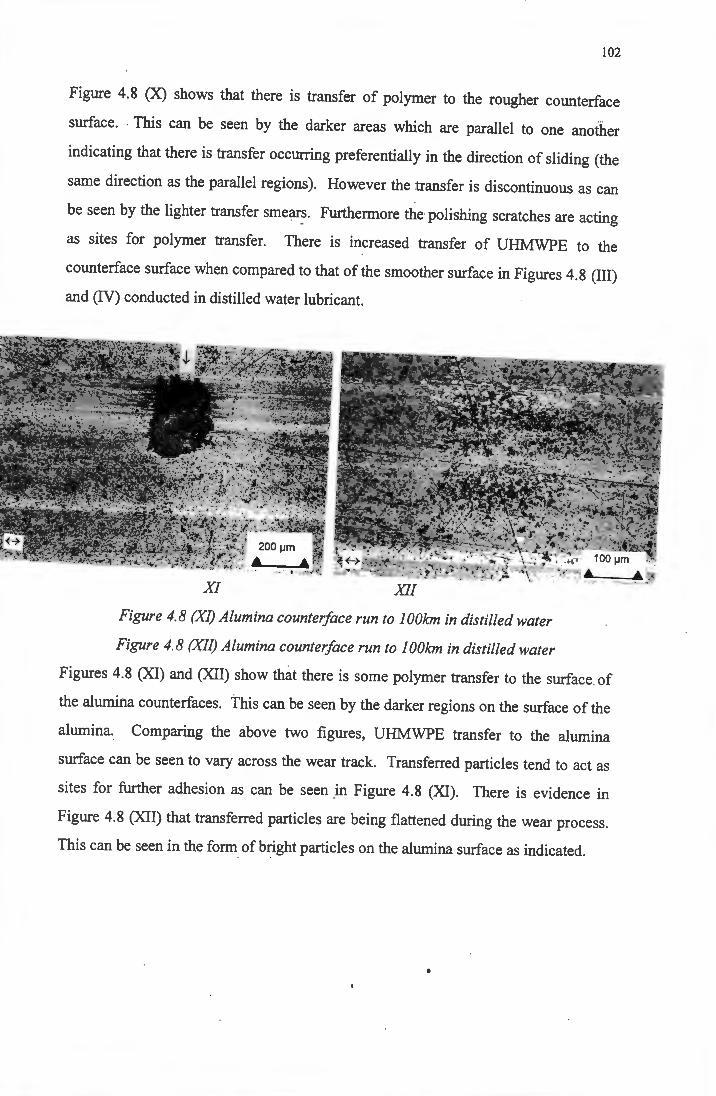
102
Figure 4.8 (X) shows that there is transfer of polymer to the rougher counterface
surface. This can be seen by the darker areas which are parallel to one another
indicating that there is transfer occurring preferentially in the direction of sliding (the
same direction as the parallel regions). However the transfer is discontinuous as can
be seen by the lighter transfer smears. Furthermore the polishing scratches are acting
as sites for polymer transfer. There is increased transfer of UHMWPE to the
counterface surface when compared to that of the smoother surface in Figures 4.8 (III)
and (IV) conducted in distilled water lubricant.
Figure 4. 8 (XI) Alumina counter/ace run to 1 OOkm in distilled water
Figure 4. 8 (XII) Alumina counter/ace run to 1 OOkm in distilled water
Figures 4.8 (XI) and (XII) show that there is some polymer transfer to the surface of
the alumina counterfaces. This can be seen by the darker regions on the surface of the
alumina. Comparing the above two figures, UHMWPE transfer to the alumina
surface can be seen to vary across the wear track. Transferred particles tend to act as
sites for further adhesion as can be seen in Figure 4.8 (XI). There is evidence in
Figure 4.8 (XII) that transferred particles are being flattened during the wear process.
This can be seen in the form of bright particles on the alumina surface as indicated.
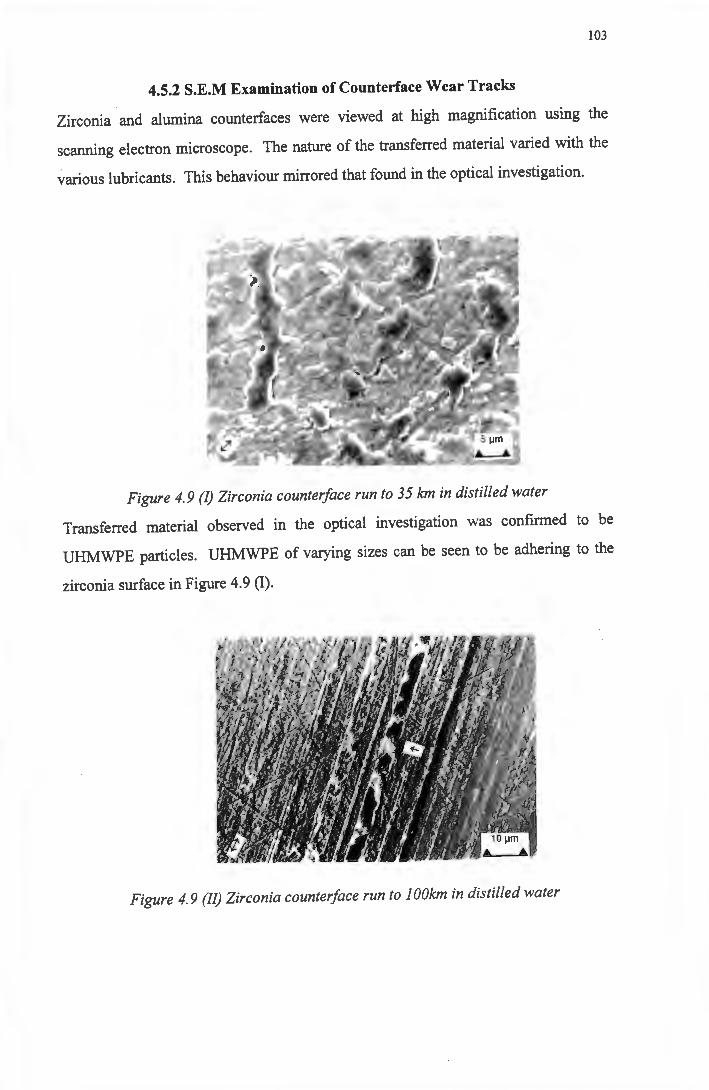
103
4.5.2 S.E.M Examination of Counterface Wear Tracks
Zirconia and alumina counterfaces were viewed at high magnification using the
scanning electron microscope. The nature of the transferred material varied with the
various lubricants. This behaviour mirrored that found in the optical investigation.
Figure 4.9 (!) Zirconia counter/ace run to 35 km in distilled water
Transferred material observed in the optical investigation was confirmed to be
UHMWPE particles. UHMWPE of varying sizes can be seen to be adhering to the
zirconia surface in Figure 4.9 (I).
Figure 4. 9 (II) Zirconia counter/ace run to 1 OOkm in distilled water
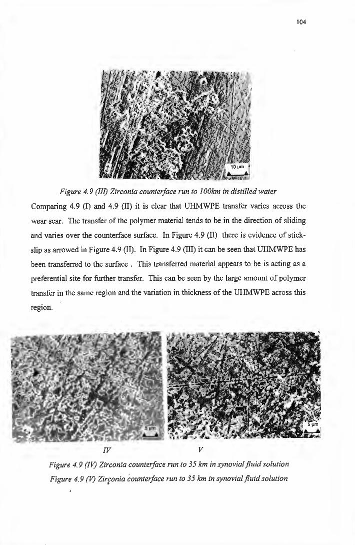
104
Figure 4. 9 (Ill) Zirconia counter/ace run to I OOkm in distilled water
Comparing 4.9 (I) and 4.9 (II) it is clear that UHMWPE transfer varies across the
wear scar. The transfer of the polymer material tends to be in the direction of sliding
and varies over the counterface surface. In Figure 4.9 (II) there is evidence of stick
slip as arrowed in Figure 4.9 (II). In Figure 4.9 (III) it can be seen that UHMWPE has
been transferred to the surface . This transferred material appears to be is acting as a
preferential site for further transfer. This can be seen by the large amount of polymer
transfer in the same region and the variation in thickness of the UHMWPE across this
region.
IV v Figure 4.9 (IV) Zirconia counter/ace run to 35 km in synovialfluid solution
Figure 4.9 (V) Zirconia counter/ace run to 35 km in synovialfluid solution •
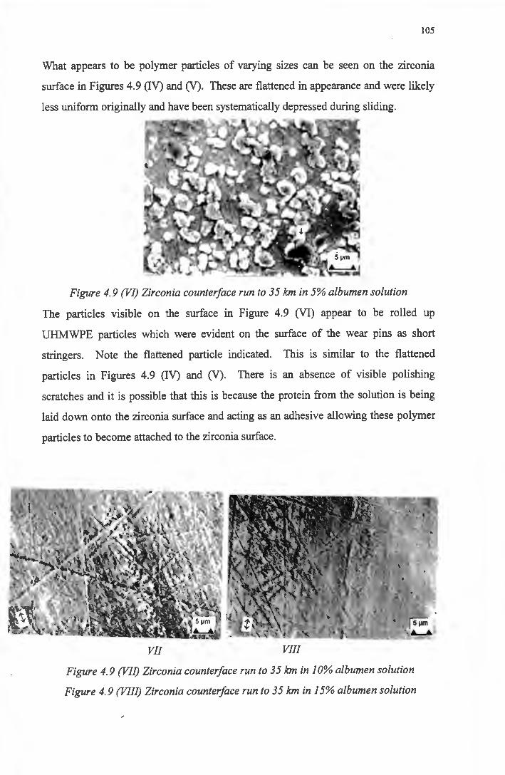
105
What appears to be polymer particles of varying sizes can be seen on the zirconia
surface in Figures 4.9 (IV) and (V). These are flattened in appearance and were likely
less uniform originally and have been systematically depressed during sliding.
Figure 4.9 (VI) Zirconia counter/ace run to 35 km in 5% albumen solution
The particles visible on the surface in Figure 4.9 (VI) appear to be rolled up
UHMWPE particles which were evident on the surface of the wear pins as short
stringers. Note the flattened particle indicated. This is similar to the flattened
particles in Figures 4.9 (IV) and (V). There is an absence of visible polishing
scratches and it is possible that this is because the protein from the solution is being
laid down onto the zirconia surface and acting as an adhesive allowing these polymer
particles to become attached to the zirconia surface.
VII VIII
Figure 4.9 (VII) Zirconia counter/ace run to 35 km in 10% albumen solution
Figure 4.9 (VIII) Zirconia counter/ace run to 35 km in 15% albumen solution
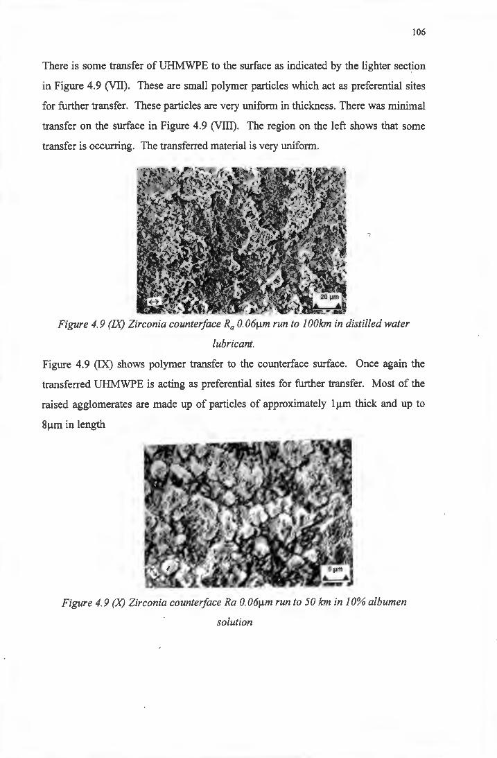
106
There is some transfer of UHMWPE to the surface as indicated by the lighter section
in Figure 4.9 (VII). These are small polymer particles which act as preferential sites
for further transfer. These particles are very uniform in thickness. There was minimal
transfer on the surface in Figure 4.9 (VIII). The region on the left shows that some
transfer is occurring. The transferred material is very uniform.
Figure 4.9 (IX) Zirconia counter/ace Ra 0.06µm run to IOOkm in distilled water
lubricant.
Figure 4.9 (IX) shows polymer transfer to the counterface surface. Once again the
transferred UHMWPE is acting as preferential sites for further transfer. Most of the
raised agglomerates are made up of particles of approximately 1 µm thick and up to
8 µm in length
Figure 4.9 (X) Zirconia counter/ace Ra 0.06µm run to 50 km in 10% albumen
solution
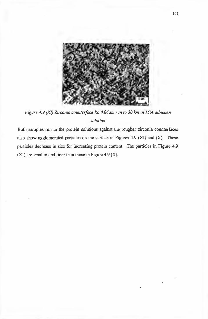
107
Figure 4.9 (XI) Zirconia counter/ace Ra 0.06µm run to 50kmin15% albumen
solution
Both samples run in the protein solutions against the rougher zirconia counterfaces
also show agglomerated particles on the surface in Figures 4.9 (XI) and (X). These
particles decrease in size for increasing protein content. The particles in Figure 4.9
(XI) are smaller and finer than those in Figure 4.9 (X).
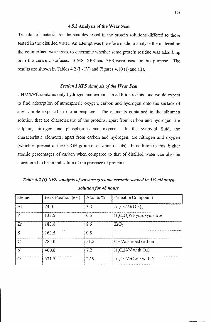
108
4.5.3 Analysis of the Wear Scar
Transfer of material for the samples tested in the protein solutions differed to those
tested in the distilled water. An attempt was therefore made to analyse the material on
the counterface wear track to determine whether some protein residue was adsorbing
onto the ceramic surfaces. SIMS, XPS and AES were used for this purpose. The
results are shown in Tables 4.2 (I - IV) and Figures 4.10 (I) and (II).
Section IXPS Analysis of the Wear Scar
UHMWPE contains only hydrogen and carbon. In addition to this, one would expect
to find adsorption of atmospheric oxygen, carbon and hydrogen onto the surface of
any sample exposed to the atmosphere. The elements contained in the albumen
solution that are characteristic of the proteins, apart from carbon and hydrogen, are
sulphur, nitrogen and phosphorous and oxygen. In the synovial fluid, the
characteristic elements, apart from carbon and hydrogen, are nitrogen and oxygen
(which is present in the COOH group of all amino acids). In addition to this, higher
atomic percentages of carbon when compared to that of distilled water can also be
considered to be an indication of the presence of proteins.
Table 4.2 (I) XPS analysis of unworn zirconia ceramic soaked in 5% albumen
solution for 48 hours
Element Peak Position ( e V) Atomic% Probable Compound
Al 74.0 3.3 A~03/ Al(OH)3
p 133.5 0.5 HxCyOzP/Hydroxyapatite
Zr 183.0 8.6 Zr02
s 163.5 0.5
c 285.0 51.2 CHI Adsorbed carbon
N 400.0 7.2 HxCyN/N with O,S
0 531.5 27.9 Al20 3/Zr02/0 with N
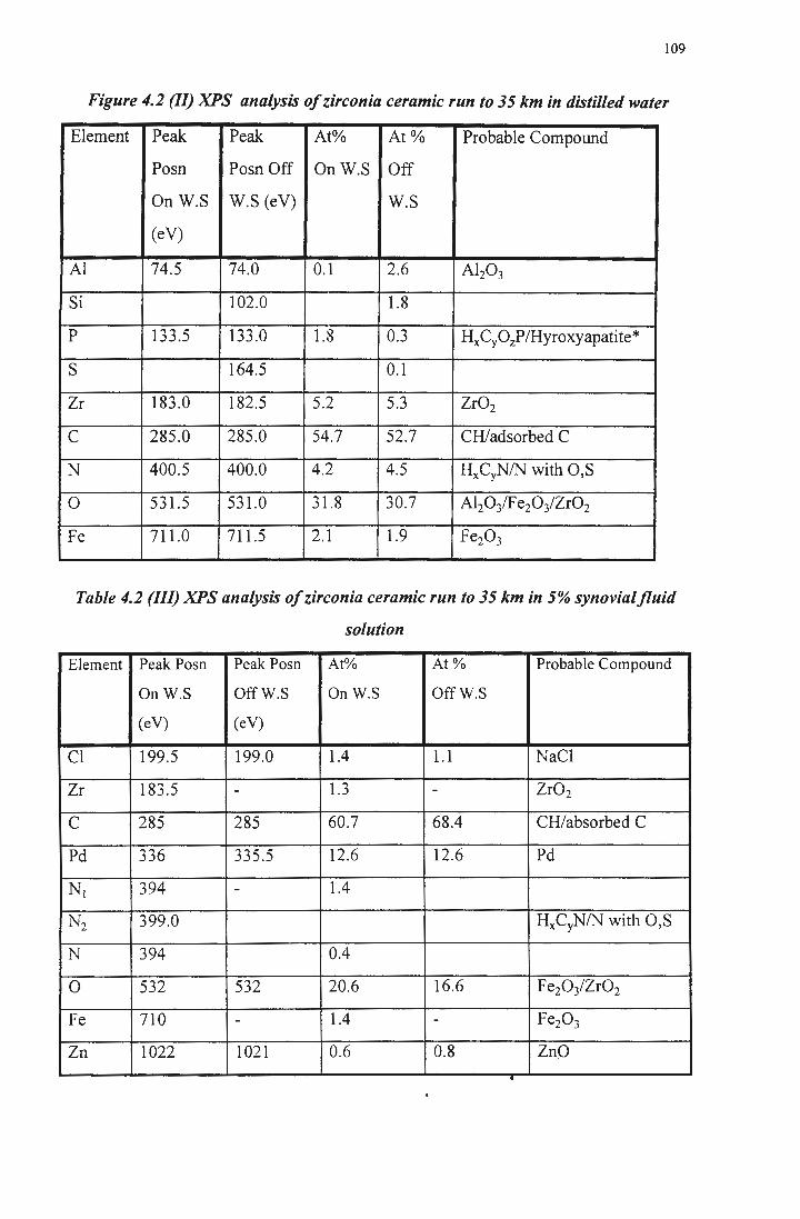
109
Figure 4.2 (II) XPS analysis of zirconia ceramic run to 35 km in distilled water
Element Peak Peak At% At% Probable Compound
Posn Posn Off OnW.S Off
OnW.S W.S (eV) W.S
(eV)
Al 74.5 74.0 0.1 2.6 Al20 3
Si 102.0 1.8
p 133.5 133.0 1.8 0.3 HxCyOzP/Hyroxyapatite*
s 164.5 0.1
Zr 183.0 182.5 5.2 5.3 Zr02
c 285.0 285.0 54.7 52.7 CH/adsorbed C
N 400.5 400.0 4.2 4.5 HxCyNIN with O,S
0 531.5 531.0 31.8 30.7 Al20iFe20 3/Zr02
Fe 711.0 711.5 2.1 1.9 Fe20 3
Table 4.2 (Ill) XPS analysis ofzirconia ceramic run to 35 km in 5% synovialfluid
solution
Element Peak Posn Peak Posn At% At% Probable Compound
OnW.S OffW.S OnW.S OffW.S
(eV) (eV)
Cl 199.5 199.0 1.4 1.1 NaCl
Zr 183.5 - 1.3 - Zr02
c 285 285 60.7 68.4 CH/absorbed C
Pd 336 335.5 12.6 12.6 Pd
Ni 394 - 1.4
N1 399.0 HxCyNIN with O,S
N 394 0.4
0 532 532 20.6 16.6 Fe20 3/Zr02
Fe 710 - 1.4 - Fe20 3
Zn 1022 1021 0.6 0.8 ZnO .
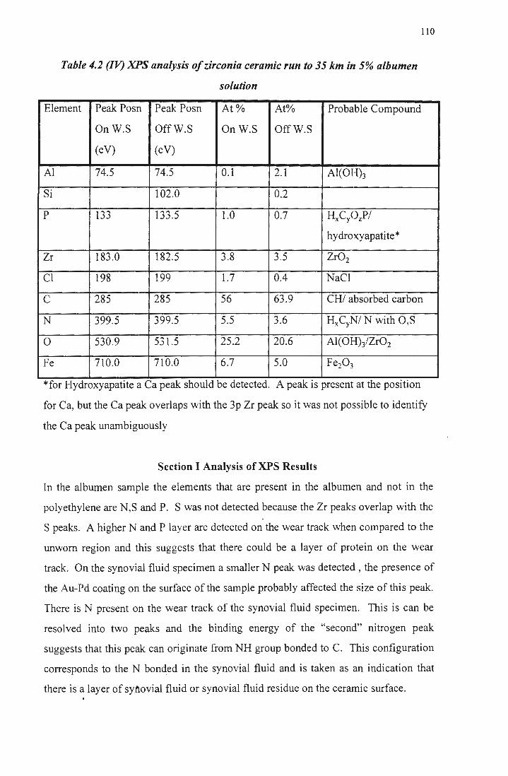
Table 4.2 (IV) XPS analysis ofzirconia ceramic run to 35 km in 5% albumen
solution
110
Element Peak Posn Peak Posn At% At% Probable Compound
OnW.S OffW.S OnW.S OffW.S
(eV) (eV)
Al 74.5 74.5 0.1 2.1 Al(OH)3
Si 102.0 0.2
p 133 133.5 1.0 0.7 HxCyOzP/
hydroxyapatite*
Zr 183.0 182.5 3.8 3.5 Zr02
Cl 198 199 1.7 0.4 NaCl
c 285 285 56 63.9 CHI absorbed carbon
N 399.5 399.5 5.5 3.6 HxCyN/ N with O,S
0 530.9 531.5 25.2 20.6 Al(OH)3/Zr02
Fe 710.0 710.0 6.7 5.0 Fe20 3
*for Hydroxyapatite a Ca peak should be detected. A peak is present at the position
for Ca, but the Ca peak overlaps with the 3p Zr peak so it was not possible to identify
the Ca peak unambiguously
Section I Analysis of XPS Results
In the albumen sample the elements that are present in the albumen and not in the
polyethylene are N,S and P. S was not detected because the Zr peaks overlap with the
Speaks. A higher N and Player are detected on the wear track when compared to the
unworn region and this suggests that there could be a layer of protein on the wear
track. On the synovial fluid specimen a smaller N peak was detected, the presence of
the Au-Pd coating on the surface of the sample probably affected the size of this peak.
There is N present on the wear track of the synovial fluid specimen. This is can be
resolved into two peaks and the binding energy of the "second" nitrogen peak
suggests that this peak can originate from NH group bonded to C. This configuration
corresponds to the N bond_ed in the synovial fluid and is taken as an indication that
there is a layer of sy:Mvial fluid or synovial fluid residue on the ceramic surface . .
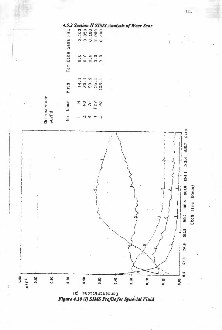
l.0
0
-----
----
---~-----
--~~-
-----------
-~----
X10
2
0_9(
)
0.00
0.70
0.60
·---· ......
...... .
O.«
l
0.3
0
0.20
0.10
·-+----
-.----
+---
· 0.
0 17
7.3
JS.4
.6
531.
9 70
9.2
886.
5 10
63.8
12
41.1
W
0.4
15
95.7
17
73.a
Etc
h
Tim
e (S
ecs)
On
1•e
arsc
ar
.\u/
"Pll
No
Nam
e N
~
MO
~
Zr
,, F
c '?
·-
1--'d
-
H 3
SS
14
.1
30
. 1
90
. 1
~iG. 1
10
6.
1
Tar
D
ias
0.0
0
.0
0.0
0
.0
0.0
~
Se
ns Fae~ ~
~
0 .1
00
~ ....
0. 0
50
§
0 .1
00
~
l.0
00
~
0. ·
100 ~
~
~
:: ;::a
<?
~ c;·
~ ~ ~ ~
~
- --
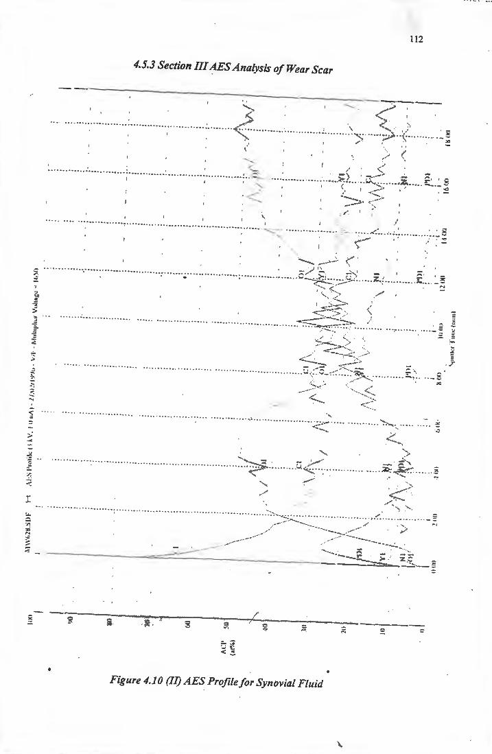
. , .~
=
--
112
4.5.3 Section III AES Analysis of Wear Scar
--------------·------------..,..... __ _ .,,..... .... >
/
"-.. , .<... ,- ....... ":'·
, , .. ~- ... · ' '\ .... , ., ·-· ··· ··· ····· ······ ·· ··-· ·· · ···· ······ ··· ···. . . , , . . ... .... .... ·'·<; .............................. .. .... ·::,· .... .. :;;.;, .. ',· ..... .... .
.'...__, (
. ~
... .... .. ......... .. ... ... .. : .... ............. .. ...... .... ........... '. ... s~- -··· - -·- - ·----· <: .......
I -··"
.... . .... ......
·· · ·-· · · - - - ~.~~ - .. :.:?; ..... ~-· -·· 2~ . ~ ~ ---......_ _ .. ...
---~- .: .>
/ "· <' •• - • - • • ••••• • •• - • ••• - - ••• • I . . ... . ..... .. - • - •• •• • • - • - • - •• •• - • •• - I ~ .... .... ~ ' ;::::::
···-i...: ... :.:· - ·· -····· - · - · · ---- · · ·:..>"' ·······""· ·· · · ··-·- · ········ -- -- -
' ,
., <. ...... . ~ '·,, <".) \-
', '· ' ,., ....... ............... ~---~ --· '·
' - _,,) I~ _:;, • - / / I ... .. ... .. .. .. ...... .... ........ .. ...... ... ........ .... .. .. .... .... ...... c~.~~...: ' .. .... ~~·~ .. .. ... .. . . - .... -
... . ;: _
······· -·-·· ··· ·· ··· ····· - ------ - - -- -- - - ---- - - - --- ---- --- - --- - - ·- -- ~~~~ - - '· __ _ ····· ·--- - -/ ::::
.~s:::::~; . . ----- . ---·-·-------- ------ -- ·- ?:;-:2:../':~-- ~- -;;
·-~ ... -::· "" -----·
-~~ --,..,. ... ....
.. .... · · ·· · ····· --···· ·· · ..... ·· ····· ... ... ...... .. ·· ·· ·· ···· -····· ·~::·.:.- .. ---
--~ .......
... .......... . . --~ .... ........
"'· ;.•
<
.::
···· · ··············· · · ·· · ·· ·· -· ·····-··· ...... .... .. ........ .. ~~-:::F.- ..... ..... v. -:<_- ....... -. .. .. .. ..... k~.~?· · · ·· ·· -
0 :;-.
··· ···· ··-··· ···· ·· ················-- · ·······
....... ~ ..... -·
---~- ·-·::
. f'•': .... ... ~ ....... - -.-· ------ ------"' =----__ :...i.._-_-_-_-_-_·------------------- - --====--·-..3:~_ z :;"·._ ::
=
=
Figure 4.10 (II) AES Profile for Synovial Fluid
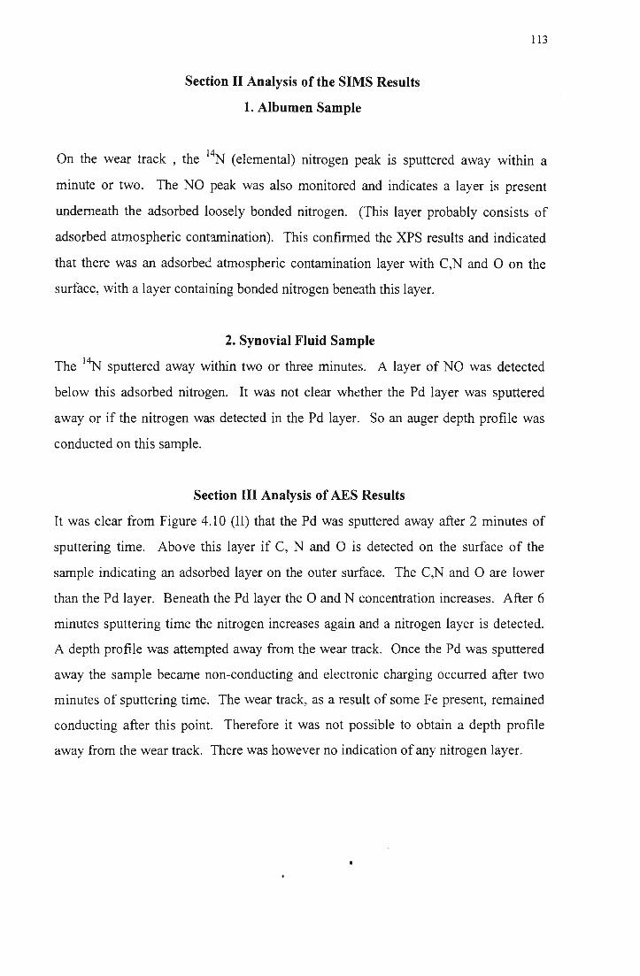
Section II Analysis of the SIMS Results
1. Albumen Sample
113
On the wear track , the 14N (elemental) nitrogen peak is sputtered away within a
minute or two. The NO peak was also monitored and indicates a layer is present
underneath the adsorbed loosely bonded nitrogen. (This layer probably consists of
adsorbed atmospheric contamination). This confirmed the XPS results and indicated
that there was an adsorbed atmospheric contamination layer with C,N and O on the
surface, with a layer containing bonded nitrogen beneath this layer.
2. Synovial Fluid Sample
The 14N sputtered away within two or three minutes. A layer of NO was detected
below this adsorbed nitrogen. It was not clear whether the Pd layer was sputtered
away or if the nitrogen was detected in the Pd layer. So an auger depth profile was
conducted on this sample.
Section III Analysis of AES Results
It was clear from Figure 4.10 (II) that the Pd was sputtered away after 2 minutes of
sputtering time. Above this layer if C, N and 0 is detected on the surface of the
sample indicating an adsorbed layer on the outer surface. The C,N and 0 are lower
than the Pd layer. Beneath the Pd layer the 0 and N concentration increases. After 6
minutes sputtering time the nitrogen increases again and a nitrogen layer is detected.
A depth profile was attempted away from the wear track. Once the Pd was sputtered
away the sample became non-conducting and electronic charging occurred after two
minutes of sputtering time. The wear track, as a result of some Fe present, remained
conducting after this point. Therefore it was not possible to obtain a depth profile
away from the wear track. There was however no indication of any nitrogen layer.
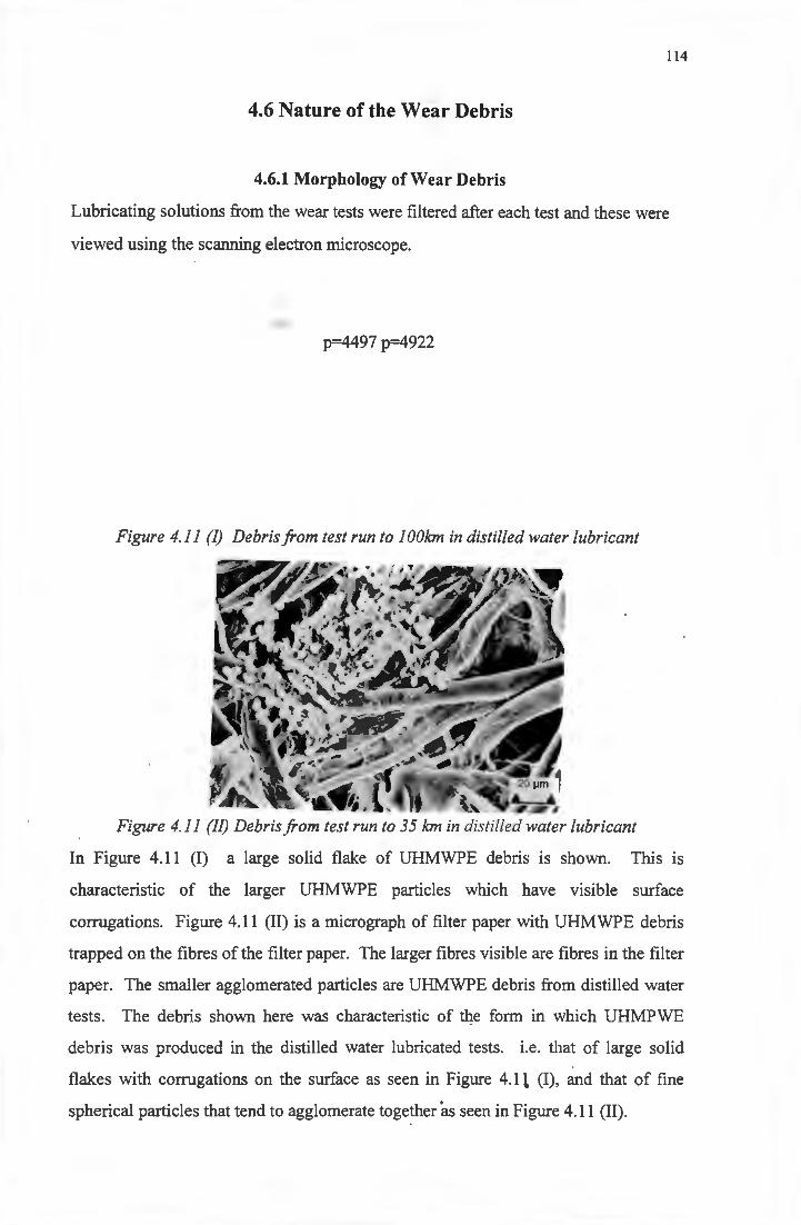
114
4.6 Nature of the Wear Debris
4.6.1 Morphology of Wear Debris
Lubricating solutions from the wear tests were filtered after each test and these were
viewed using the scanning electron microscope.
p=4497 p=4922
Figure 4.11 (I) Debris from test run to 1 OOkm in distilled water lubricant
Figure 4.11 (II) Debris from test run to 35 km in distilled water lubricant
In Figure 4.11 (I) a large solid flake of UHMWPE debris is shown. This is
characteristic of the larger UHMWPE particles which have visible surface
corrugations. Figure 4.11 (II) is a micrograph of filter paper with UHMWPE debris
trapped on the fibres of the filter paper. The larger fibres visible are fibres in the filter
paper. The smaller agglomerated particles are UHMWPE debris from distilled water
tests. The debris shown here was characteristic of tqe form in which UHMPWE
debris was produced in the distilled water lubricated tests. i.e. that of large solid
flakes with corrugations on the surface as seen in Figure 4.1 i (I), and that of fine
spherical particles that tend to agglomerate together 'as seen in Figure 4.11 (II).
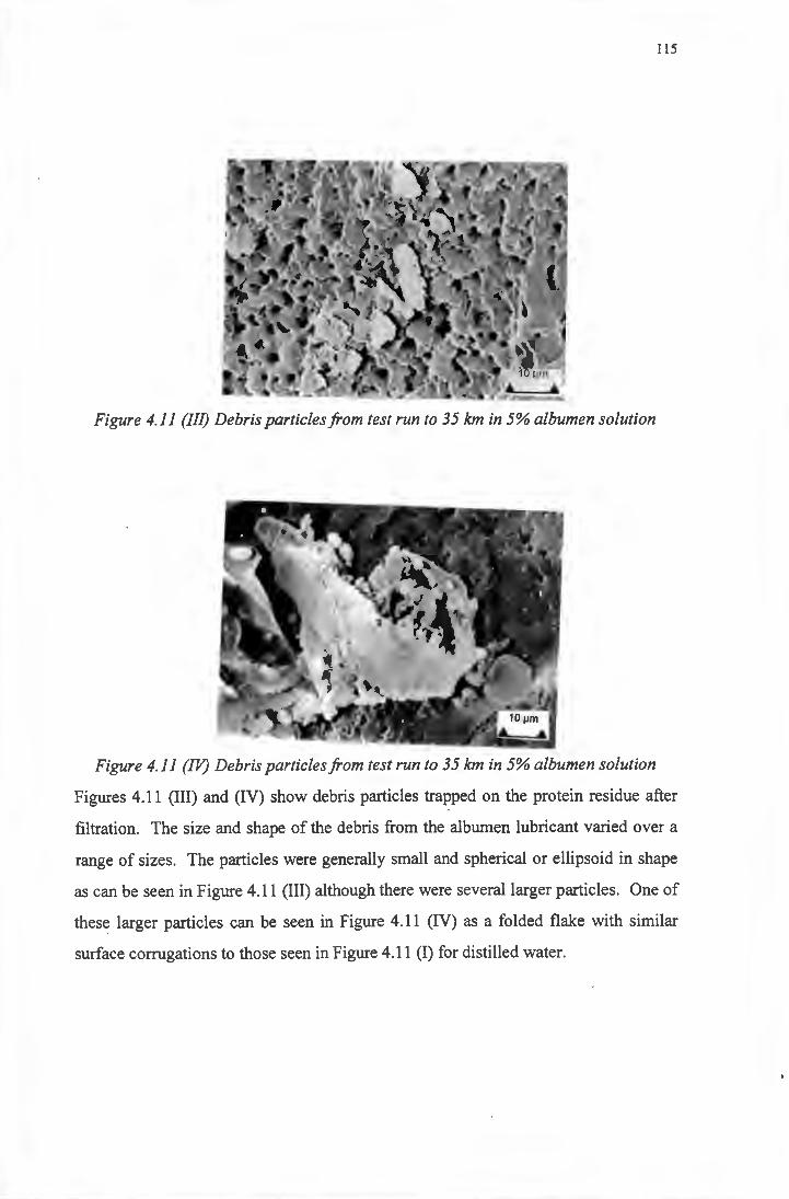
115
Figure 4.11 (III) Debris particles from test run to 35 km in 5% albumen solution
Figure 4.11 (IV) Debris particles from test run to 35 km in 5% albumen solution
Figures 4.11 (III) and (IV) show debris particles trapped on the protein residue after
filtration. The size and shape of the debris from the albumen lubricant varied over a
range of sizes. The particles were generally small and spherical or ellipsoid in shape
as can be seen in Figure 4.11 (III) although there were several larger particles. One of
these larger particles can be seen in Figure 4.11 (IV) as a folded flake with similar
surface corrugations to those seen in Figure 4.11 (I) for distilled water.
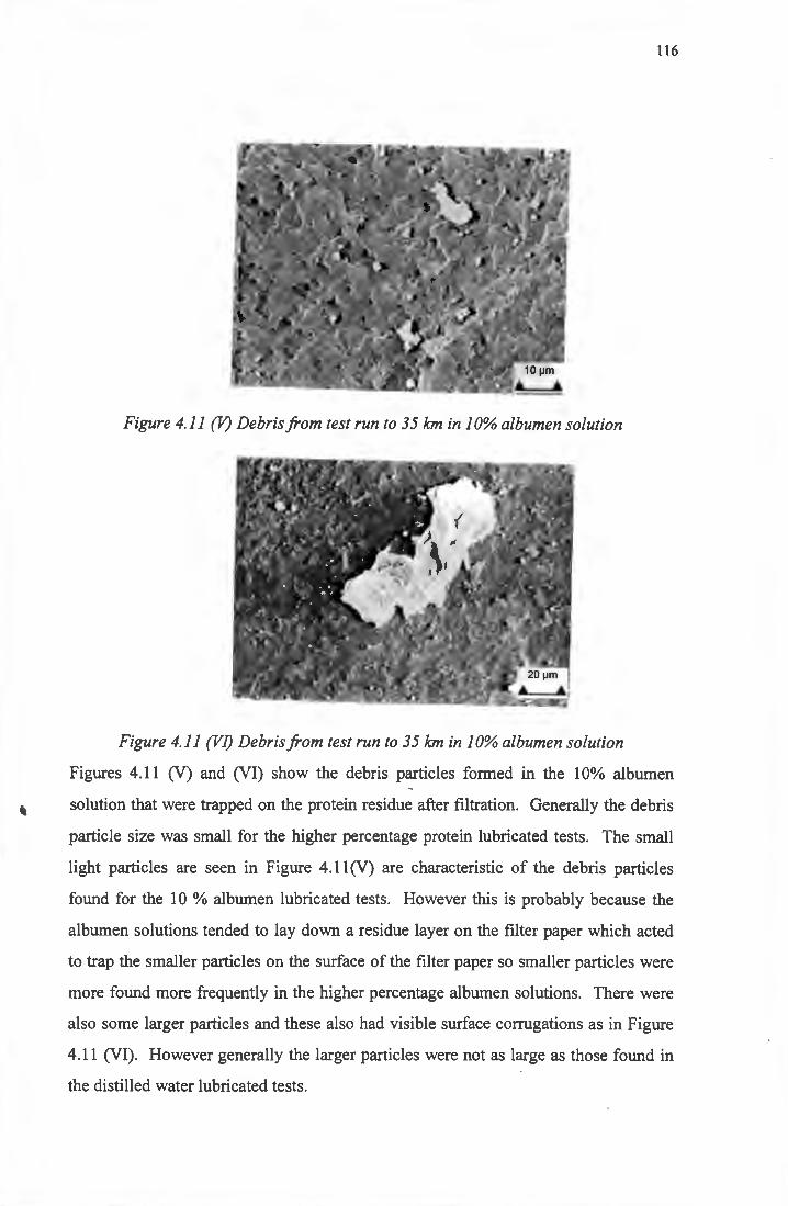
116
Figure 4.11 (V) Debris from test run to 35 km in 10% albumen solution
Figure 4.11 (VI) Debris from test run to 35 km in 10% albumen solution
Figures 4.11 (V) and (VI) show the debris particles formed in the 10% albumen
solution that were trapped on the protein residue after filtration. Generally the debris
particle size was small for the higher percentage protein lubricated tests. The small
light particles are seen in Figure 4.11 (V) are characteristic of the debris particles
found for the 10 % albumen lubricated tests. However this is probably because the
albumen solutions tended to lay down a residue layer on the filter paper which acted
to trap the smaller particles on the surface of the filter paper so smaller particles were
more found more frequently in the higher percentage albumen solutions. There were
also some larger particles and these also had visible surface corrugations as in Figure
4.11 (VI). However generally the larger particles were not as large as those found in
the distilled water lubricated tests.
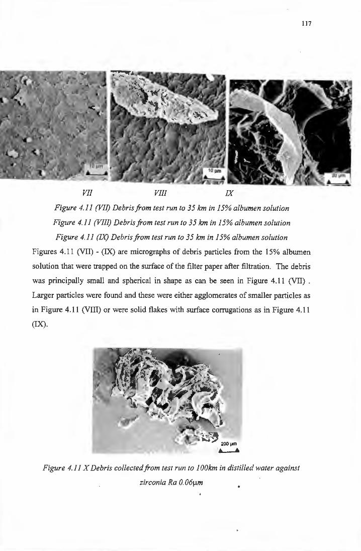
VII VIII IX
Figure 4.11 (VII) Debris from test run to 35 km in 15% albumen solution
Figure 4.11 (VIII) Debris from test run to 35 km in 15% albumen solution
117
Figure 4.11 (IX) Debris from test run to 35 km in 15% albumen solution
Figures 4.11 (VII) - (IX) are micrographs of debris particles from the 15% albumen
solution that were trapped on the surface of the filter paper after filtration. The debris
was principally small and spherical in shape as can be seen in Figure 4.11 (VII) .
Larger particles were found and these were either agglomerates of smaller particles as
in Figure 4.11 (VIII) or were solid flakes with surface corrugations as in Figure 4.11
(IX).
200 µm
• • Figure 4.11 X Debris collected from test run to 1 OOkm in distilled water against
zirconia Ra 0. 06µm
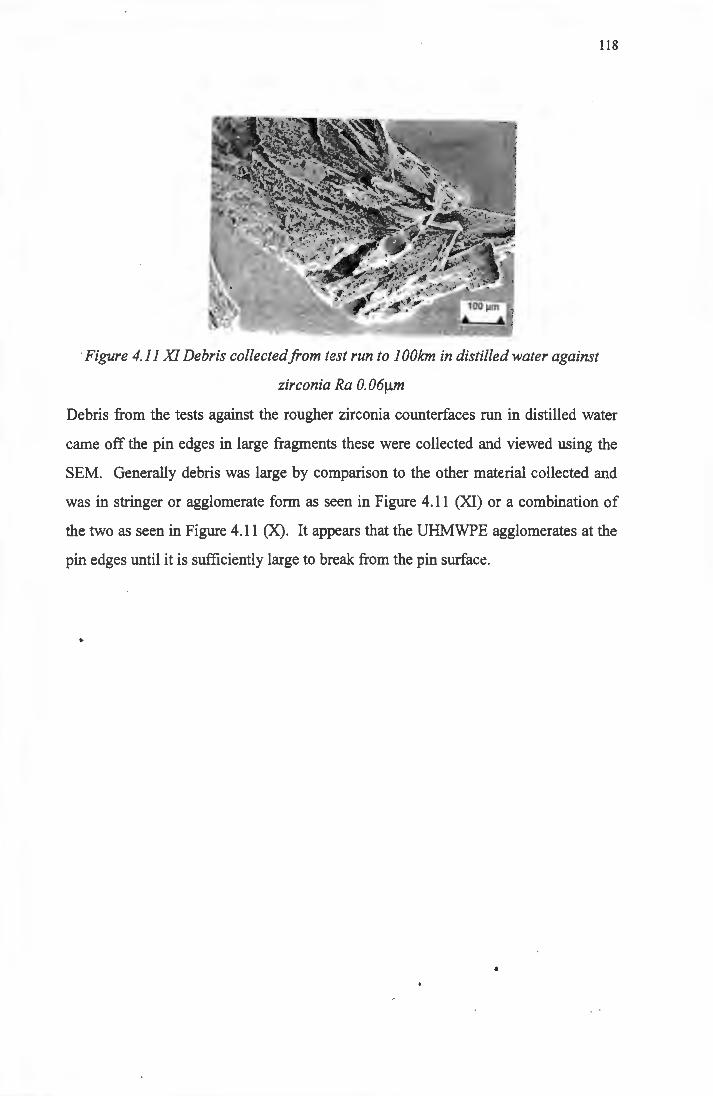
118
Figure 4.11 XI Debris collected from test run to 1 OOkm in distilled water against
zirconia Ra 0. 06µm
Debris from the tests against the rougher zirconia counterfaces run in distilled water
came off the pin edges in large fragments these were collected and viewed using the
SEM. Generally debris was large by comparison to the other material collected and
was in stringer or agglomerate form as seen in Figure 4.11 (XI) or a combination of
the two as seen in Figure 4.11 (X). It appears that the UHMWPE agglomerates at the
pin edges until it is sufficiently large to break from the pin surface.
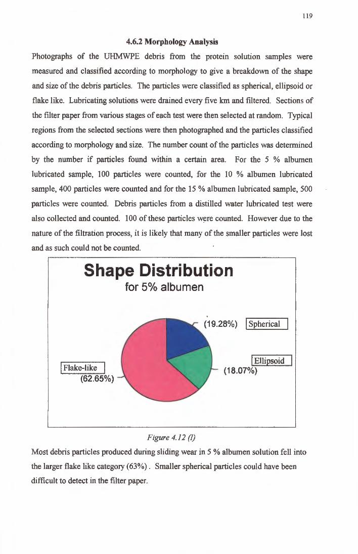
119
4.6.2 Morphology Analysis
Photographs of the UHMWPE debris from the protein solution samples were
measured and classified according to morphology to give a breakdown of the shape
and size of the debris particles. The particles were classified as spherical, ellipsoid or
flake like. Lubricating solutions were drained every five km and filtered. Sections of
the filter paper from various stages of each test were then selected at random. Typical
regions from the selected sections were then photographed and the particles classified
according to morphology and size. The number count of the particles was determined
by the number if particles found within a certain area. For the 5 % albumen
lubricated sample, 100 particles were counted, for the 10 % albumen lubricated
sample, 400 particles were counted and for the 15 % albumen lubricated sample, 500
particles were counted. Debris particles from a distilled water lubricated test were
also collected and counted. 100 of these particles w~re counted. However due to the
nature of the filtration process, it is likely that many of the smaller particles were lost
and as such could not be counted.
Shape Distribution
I Flake-like I (62.65%)
for 5o/o albumen
Figure 4.12 (!)
(19.28%) I Spherical
I Ellipsoid (18.07%)
Most debris particles produced during sliding wear in 5 % albumen solution fell into
the larger flake like category (63%). Smaller spherical particles could have been
difficult to detect in the filter paper.
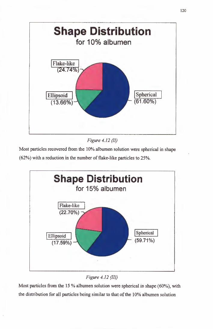
Shape Distribution for 10°/o albumen
I Flake-like l (24.74%
I Ellipsoid I (13.66%)
Figure 4.12 (JI)
I Spherical (61.60%)
120
Most particles recovered from the 10% albumen solution were spherical in shape
(62%) with a reduction in the number of flake-like particles to 25%.
Shape Distribution
I Ellipsoid
(17.59%)
for 15o/o albumen
Figure 4.12 (III)
I spherical
(59.71%)
Most particles from the 15 % albumen solution were spherical in shape (60%), with
the distribution for all particles being similar to that of the 10% albumen solution
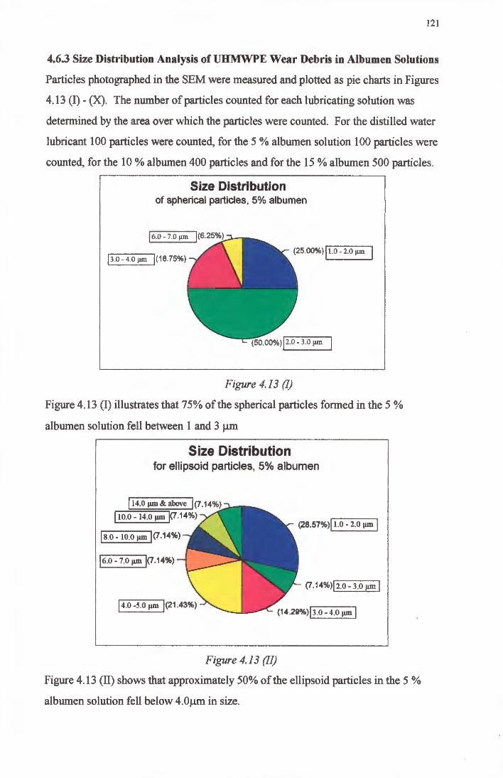
121
4.6.3 Size Distribution Analysis ofUHMWPE Wear Debris in Albumen Solutions
Particles photographed in the SEM were measured and plotted as pie charts in Figures
4 .13 (I) - (X). The number of particles counted for each lubricating solution was
determined by the area over which the particles were counted. For the distilled water
lubricant 100 particles were counted, for the 5 % albumen solution 100 particles were
counted, for the 10 % albumen 400 particles and for the 15 % albumen 500 particles.
Size Distribution of spherical particles, 5% albumen
j6.0- 7.0 µm
j3.0-4.0 µm 1(18.75%) (25.00%) j 1.0 - 2.0 µm
Figure 4.13 (I)
Figure 4.13 (I) illustrates that 75% of the spherical particles formed in the 5 %
albumen solution fell between 1 and 3 µm
Size Distribution for ellipsoid particles, 5% albumen
114.0µm&above 1(7.14%)
I 10.0 - 14.0 µm j(7.14%)
js.0-10.oµm 1<7.14%)
16.0 - 7.0 µm j(7.14%)
j 4.0 -5.0 µm 1<21.43%)
Figure 4.13 (II)
<2a.s1%>l 1.o - 2.0 µm 1
(7.14%>12.0-3.o µm I
Figure 4.13 (II) shows that approximately 50% of the ellipsoid particles in the 5 %
albumen solution fell below 4.0µm in size.
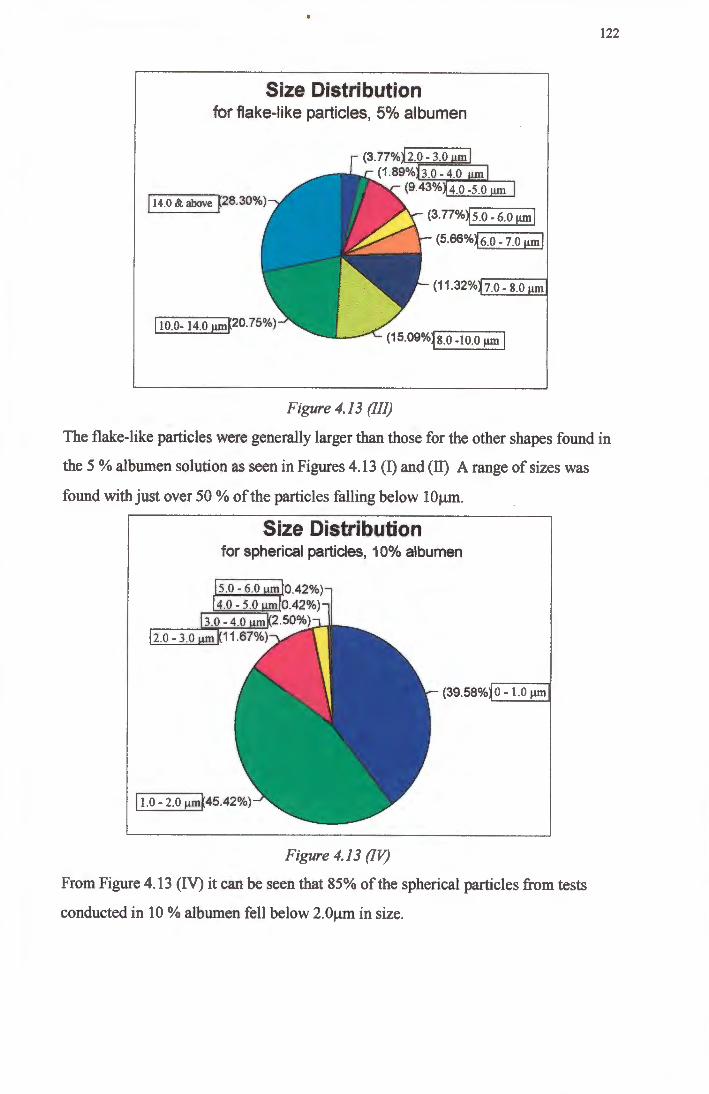
Size Distribution for flake-like particles, 5% albumen
j 14.0 & above ~28.30%)
I 10.0- 14.o µmFo.75%)
(3.77%j2.0-3.0 um! (1.89% 3.0 - 4.0
(9.43% 4.0 -5.0
• ·,.~ . .
. .
(3 . 77%~5.0-6.0 µmj
(5.66%~6.0- 7.0 µmj
(11 .32% 7.0 - 8.0 m
· ····aam Figure 4. 13 (Ill)
122
The flake-like particles were generally larger than those for the other shapes found in
the 5 % albumen solution as seen in Figures 4.13 (I) and (II) A range of sizes was
found with just over 50 % of the particles falling below lOµm .
Size Distribution for spherical particles, 10% albumen
2.0 - 3.0
(39.58% 0 - 1.0 µm
j i.o - 2.0 µmK45.42%)
Figure 4. 13 (IV)
From Figure 4.13 (IV) it can be seen that 85% of the spherical particles from tests
conducted in 10 % albumen fell below 2.0µm in size .
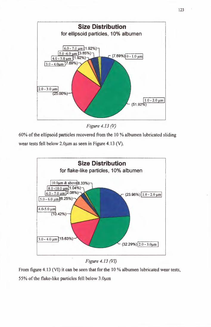
Size Distribution for ellipsoid particles, 10% albumen
2.0 - 3.0 µm .00%)
Figure 4.13 (V)
~I.0-2. 0 µm I (51.92°0)
60% of the ellipsoid particles recovered from the 10 % albumen lubricated sliding
wear tests fell below 2.0µm as seen in Figure 4.13 (V).
Size Distribution for flake-like particles, 10% albumen
,4.0-5.0 µml (10.42%)
j 3.0 - 4.0 µmp 5.63%)
Figure 4.13 (VI)
(23.96%) j I.o - 2.0 µml
(322e%)j2.o - 3.oµm I
123
From figure 4 .13 (VI) it can be seen that for the 10 % albumen lubricated wear tests,
55% of the flake-like particles fell below 3.0µm
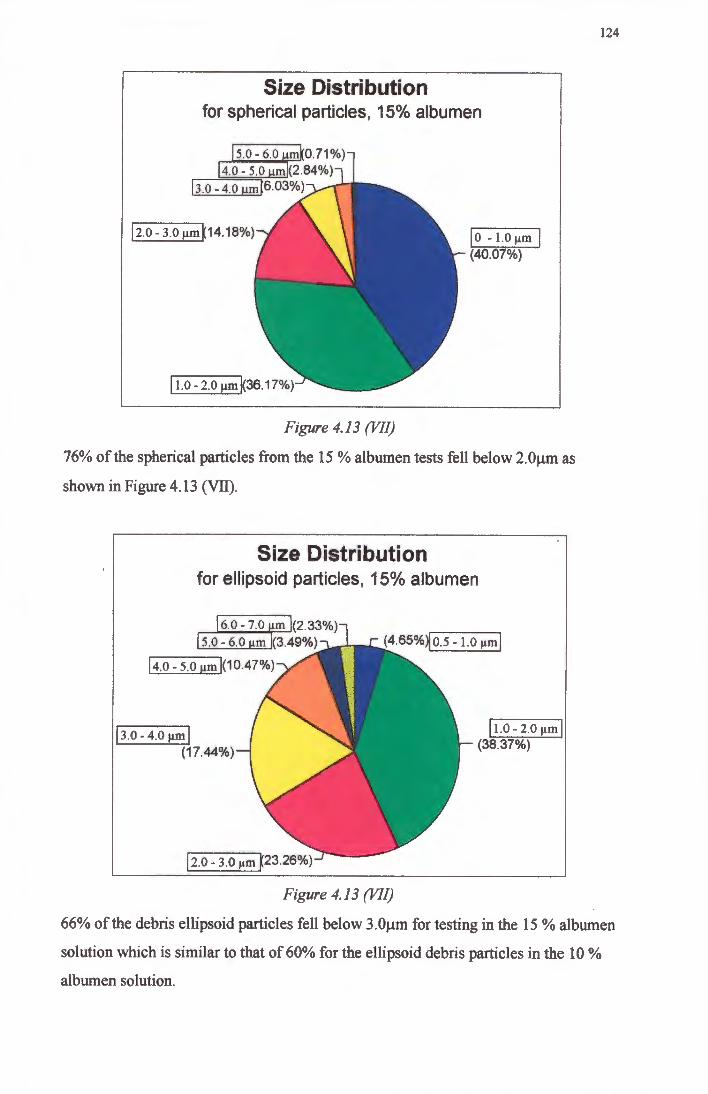
Size Distribution for spherical particles, 15% albumen
12.0- 3.o µmK14.1a%)
Figure 4.13 (VII)
jo - 1.0 µm I (40.07%)
76% of the spherical particles from the 15 % albumen tests fell below 2.0µm as
shown in Figure 4.13 (VII).
Size Distribution for ellipsoid particles, 15% albumen
6.0 - 7.0 m (2.33%) 5.0 - 6.0 m (3.49%)
14.0- 5.0 µmj(10.47%)
j 3.o - 4.o µm I (17.44%)
Figure 4.13 (VII)
j i.o - 2.0 µm I (38.37%)
124
66% of the debris ellipsoid particles fell below 3.0µm for testing in the 15 % albumen
solution which is similar to that of 60% for the ellipsoid debris particles in the 10 %
albumen solution.
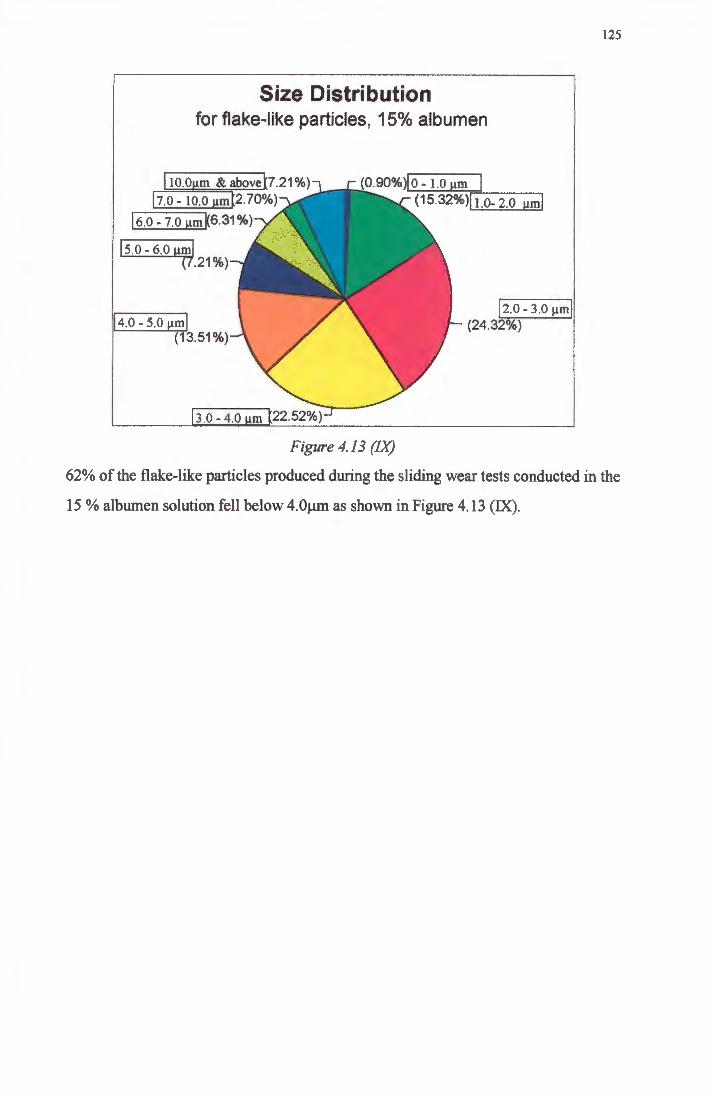
Size Distribution for flake-like particles, 15% albumen
I 10.0µm & abovet?.21%) 17.0 - 10.0 µm[2.70%)
I 6.o - 1.0 µm K6.31 %)
I 5.0 - 6.0 µml (7.21%)
I 4.0 - 5.0 µml (13.51%)
3.0-4.0 m
(0.90%)10 - 1.0 µm
(15.32%)11.0- 2.0 µml
!2.0 - 3.0 µml (24.32%)
Figure 4.13 (IX)
125
62% of the flake-like particles produced during the sliding wear tests conducted in the
15 % albumen solution fell below 4. Oµm as shown in Figure 4 .13 (IX).
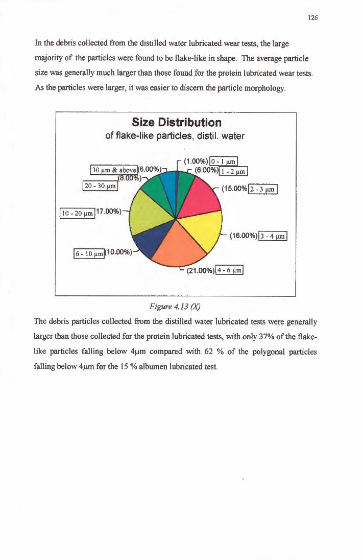
126
In the debris collected from the distilled water lubricated wear tests, the large
majority of the particles were found to be flake-like in shape. The average particle
size was generally much larger than those found for the protein lubricated wear tests.
As the particles were larger, it was easier to discern the particle morphology.
Size Distribution of flake-like particles, distil. water
130 µm & above~6.00%) r---_,(8.00%) l.20- 30 µml
I 10 _ 20 µml17.00%)
(1.00%) 0-1 m (6.00%) 1 - 2 m
<1s.00%J2 - 3 µm I
(16.00%>13 - 4 µm I
Figure 4.13 (X)
The debris particles collected from the distilled water lubricated tests were generally
larger than those collected for the protein lubricated tests, with only 37% of the flake
like particles falling below 4µm compared with 62 % of the polygonal particles
falling below 4µm for the 15 % albumen lubricated test.
127
CHAPTERS
DISCUSSION
5.1 Introduction
The tribological behaviour of a wear system is influenced by various factors. These
include the counterface roughness, the bearing pressure and the lubricating medium.
The wear behaviour of prosthetic joints is also influenced by all these factors. In
order to understand and accurately predict the wear behaviour of a prosthesis, it is
necessary to generate test conditions which approximate those that the prosthesis will
undergo in the body.
An attempt has been made in this work to simulate conditions similar to those in the
physiological environment by conducting sliding wear tests of UHMWPE against
ceramic counterfaces in lubricating media containing proteins. The wear behaviour of
UHMWPE in these environments is compared to similar couples in alternative
lubricating media.
128
5.2 Friction and Wear Behavio·ur of UHMWPE
5.2.1 Saline Lubricated Sliding Wear
Tests were conducted using UHMWPE sliding against zirqonia counterfaces with a
surface roughness (RJ O.Olµm in a saline environment. There was an incubation
period of about 5 km before any measurable wear took place. The wear rate then
remained steady at 2.13 x 1 o-6 mm3 /Nm until approximately 40km at which point the
wear rate decreased slightly. This initial wear rate was significantly higher than that
for any of the other lubricants used. This was attributed to the fact that iron oxide
(rust) was observed in the wear apparatus and which was thought to be acting as a
third body, thereby increasing the volume loss of the UHMWPE. It is believed that
the reduction in wear rate at 40km was a result of the formation of a polymer transfer
film on the surface of the zirconia counterface. This transfer layer was observed to be
coherent in most regions across the wear track.
The measured counterface roughness, Ra, was found to increase to a value of 0.2µm
at 30 km after which there was a general reduction in Ra, albeit with some scatter of
results. This scatter can be attributed to the fact that the transfer layer was not
completely coherent across the surface and that shear of UHMWPE was occurring
from parts of the surface of the transfer layer. As the wear process was clearly
affected by the presence of the corrosion products, further analysis of the results of the
saline solution lubricated tests was abandoned.
5.2.2 Water Lubricated Sliding Wear
Tests were conducted using UHMWPE sliding against zirconia ceramic surfaces with
a counterface roughness, Ra of O.Olµm in a distilled water environment. The volume·
loss for the water lubricated wear tests showed ari incubation period of 'no wear' for
approximately 10 km after which the wear rate was steady at 1.85 x 10⁻⁷ mm3/Nm.
During the incubation period, when little or no polymer is lost from the UHMWPE
surface, there is a build up of plastic strain and orientation of the polymer chains in
the interfacial layers. This is associated with the formation of a fibrous structure [26] • and a twinning process [31, 117]. The evidence of subsurface deformation seen in the
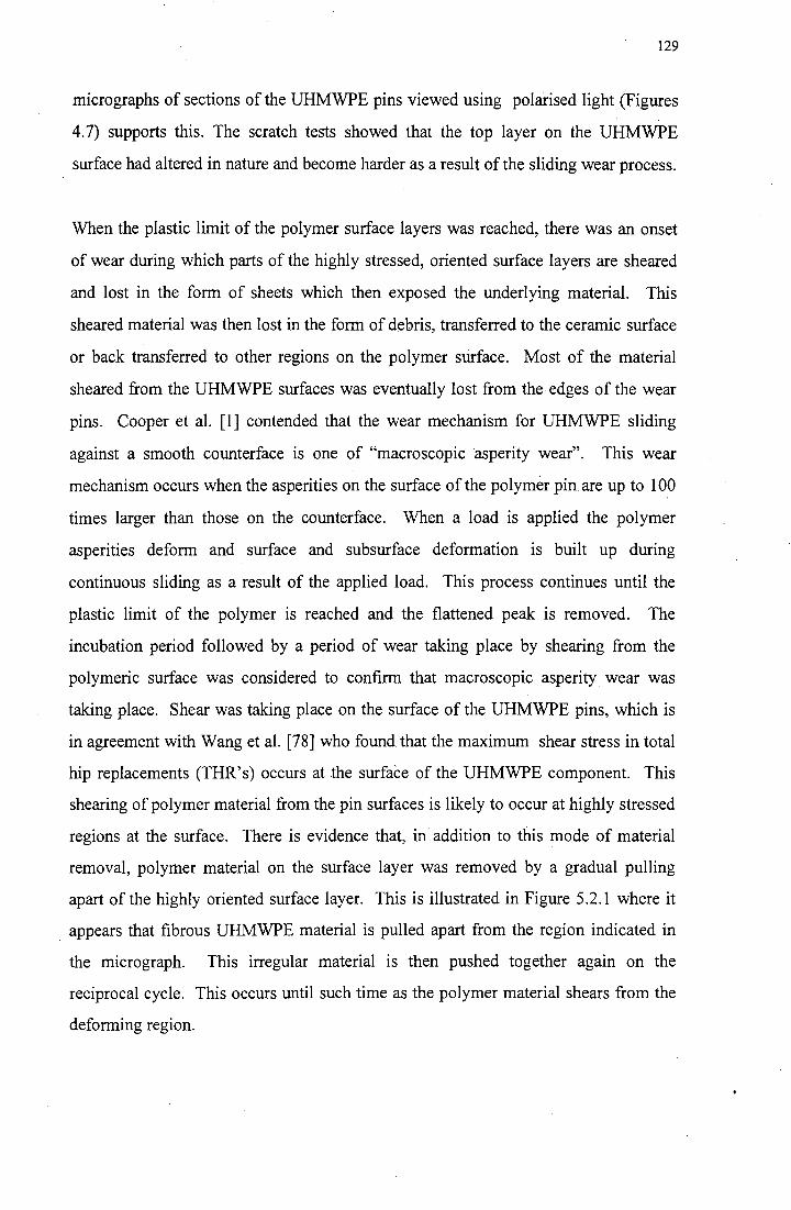
129
micrographs of sections of the UHMWPE pins viewed using polarised light (Figures
4.7) supports this. The scratch tests showed that the top layer on the UHMWPE
surface had altered in nature and become harder as a result of the sliding wear process.
When the plastic limit of the polymer surface layers was reached, there was an onset
of wear during which parts of the highly stressed, oriented surface layers are sheared
and lost in the form of sheets which then exposed the underlying material. This
sheared material was then lost in the form of debris, transferred to the ceramic surface
or back transferred to other regions on the polymer surface. Most of the material
sheared from the UHMWPE surfaces was eventually lost from the edges of the wear
pins. Cooper et al. [1] contended that the wear mechanism for UHMWPE sliding
against a smooth counterface is one of "macroscopic asperity wear". This wear
mechanism occurs when the asperities on the surface of the polymer pin are up to 100
times larger than those on the counterface. When a load is applied the polymer
asperities deform and surface and subsurface deformation is built up during
continuous sliding as a result of the applied load. This process continues until the
plastic limit of the polymer is reached and the flattened peak is removed. The
incubation period followed by a period of wear taking place by shearing from the
polymeric surface was considered to confirm that macroscopic asperity wear was
taking place. Shear was taking place on the surface of the UHMWPE pins, which is
in agreement with Wang et al. [78] who found that the maximum shear stress in total
hip replacements (THR' s) occurs at the surface of the UHMWPE component. This
shearing of polymer material from the pin surfaces is likely to occur at highly stressed
regions at the surface. There is evidence that, in addition to this mode of material
removal, polymer material on the surface layer was removed by a gradual pulling
apart of the highly oriented surface layer. This is illustrated in Figure 5.2.1 where it
appears that fibrous UHMWPE material is pulled apart from the region indicated in
the micrograph. This irregular material is then pushed together again on the
reciprocal cycle. This occurs until such time as the polymer material shears from the
deforming region.
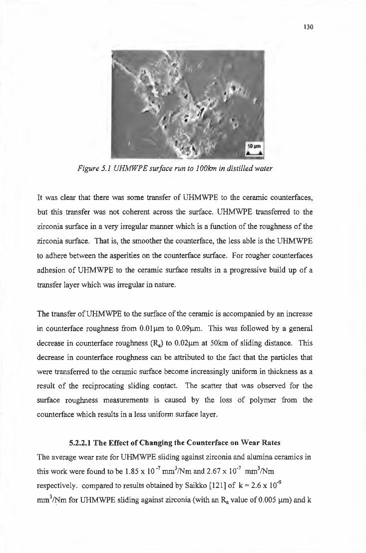
130
Figure 5.1 UHJv!WP E surface run to 1 OOkm in distilled water
It was clear that there was some transfer of UHMWPE to the ceramic counterfaces,
but this transfer was not coherent across the surface. UHMWPE transferred to the
zirconia surface in a very irregular manner which is a function of the roughness of the
zirconia surface. That is, the smoother the counterface, the less able is the UHMWPE
to adhere between the asperities on the counterface surface. For rougher counterfaces
adhesion of UHMWPE to the ceramic surface results in a progressive build up of a
transfer layer which was irregular in nature.
The transfer of UHMWPE to the surface of the ceramic is accompanied by an increase
in counterface roughness from O.Olµm to 0.09µm. This was followed by a general
decrease in counterface roughness (RJ to 0.02µm at 50km of sliding distance. This
decrease in counterface roughness can be attributed to the fact that the particles that
were transferred to the ceramic surface become increasingly uniform in thickness as a
result of the reciprocating sliding contact. The scatter that was observed for the
surface roughness measurements is caused by the loss of polymer from the
counterface which results in a less uniform surface layer.
5.2.2.1 The Effect of Changing the Counterface on Wear Rates
The average wear rate for UHMWPE sliding against zirconia and alumina ceramics in
this work were found to be 1.85 x 10⁻⁷ mm3/Nm and 2.67 x 10⁻⁷ mm3/Nm
respectively. compared to results obtained by Saikko [121] of k = 2.6 x 10⁻⁹
mm3/Nm for UHMWPE sliding against zirconia (with an Ra value of 0.005 µm) and k
131
= 3.3 x 10⁻⁹ mm3/Nm for UHMWPE sliding against alumina (with an Ra value of
0.005µm). The wear ofUHMWPE against alumina and zirconia at similar Ra values
(0.02µm on all counterfaces) has been investigated by Kumar et al. [122] and results
were as follows
: for zirconia against UHMWPE in distilled water k = 3.8 x 10⁻⁸ mm3/Nm
: for alumina against UHMPWE in distilled water k = 6.8 x 1 o-8 mm3 /Nm
In this work the improved wear behaviom of zirconia when compared to alumina can
be attributed principally to the differences in surface roughness. Zirconia has a finer
grain size than alumina which allows a better surface finish which has been shown to
reduce wear [115]. Alumina is susceptible to grain pull-out during the polishing
process and thus highly polished surfaces tend to be associated with porosity on the
surface of the alumina ceramic as can be seen in Figure 4.9 (II). This porosity has an
adverse effect on the wear process in that polymer tends to fill these pores. The
porosity also effectively prevents a good surface finish equivalent to that of the
zirconia from being achieved. In this work the best surface finish that was obtained
on zirconia was O.Olµm whilst that on alumina was 0.04µm.
5.2.2.2 The Effect of Changing the Counterface on the Coefficient of Friction
For both the zirconia and the alumina counterfaces, the friction coeffiGient decreased
as sliding distance increased and then stabilised at a sliding distance of 40 km. For
the alumina ceramic the coefficient of friction varied from a high of 0.17 to a low of
0.07. The coefficient of friction of the zirconia ceramic varied from a high of 0.14 to
a low of 0.03. These results are similar to those of Saikko [121] who obtained a high
of 0.2 and a low of 0.06 for the alumina ceramic and a high of 0.2 and a low of 0.05
for the zirconia ceramic. It is likely that the reduction of coefficient of friction is a
result of the flattening of any UHMWPE particles which have been transferred to the
ceramic surface. Transferred particles are thought to be forced against the ceramic
surface and smeared across the counterface during sliding and in so doing become
more adherent to the surface. This effect can be seen in Figure 4.9 (II). Effectively
the surface area over which sliding is being conducted is not only changed but is •
reduced, leading to a decrease in the coefficient of friction.
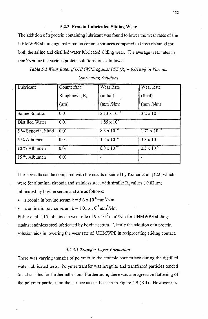
132
5.2.3 Protein Lubricated Sliding Wear
The addition of a protein containing lubricant was found to lower the wear rates of the
UHMWPE sliding against zirconia ceramic surfaces compared to those obtained for
both the saline and distilled water lubricated sliding wear. The average wear rates in
mm3 /Nm for the various protein solutions are as follows:
Table 5.1 Wear Rates ifUHMWPE against PSZ (Ra= O.Olµm) in Various
Lubricating Solutions
Lubricant Counterface Wear Rate Wear Rate
Roughness , Ra (initial) (final)
(µm) (mm3/Nm) (mm3/Nm)
Saline Solution 0.01 2.13 x 10 -o 3.2 x 10 .·/
Distilled Water 0.01 1.85 x 10 ·/
5 % Synovial Fluid 0.01 8.3 x 10 -6 1.71 x 10 -6
5 %Albumen 0.01 3.2 x 10 -o 3.8 x 10 •/
10 %Albumen 0.01 6.0 x 10 -6 2.5 x 10 .,
15 %Albumen 0.01 - -
These results can be compared with the results obtained by Kumar et al. [122] which
were for alumina, zirconia and stainless steel with similar Ra values ( 0.02µm)
lubricated by bovine serum and are as follows:
• zirconia in bovine serum k = 5.6 x 10·8 mm3 /Nm
• alumina in bovine serum k = 1.01x10·7 mm3/Nm
Fisher et al [115] obtained a wear rate of 9 x 10·9 mm3 /Nm for UHMWPE sliding
against stainless steel lubricated by bovine serum. Clearly the addition of a protein
solution aids in lowering the wear rate of UHMWPE in reciprocating sliding contact.
5.2.3.1 Transfer Layer Formation
There was varying transfer of polymer to the ceramic counterface during the distilled
water lubricated tests. Polymer transfer was irregular and transferred particles tended
to act as sites for further adhesion. Furthermore, there was a progressive flattening of
the polymer particles on the surface as can be seen in Figure 4.9 (XII). However it is
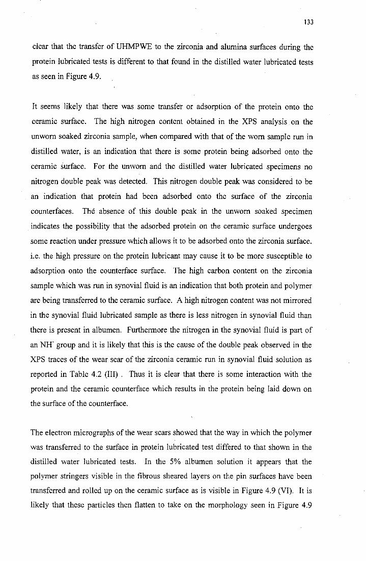
133
clear that the transfer of UHMPWE to the zirconia and alumina surfaces during the
protein lubricated tests is different to that found in the distilled water lubricated tests
as seen in Figure 4.9.
It seems likely that there was some transfer or adsorption of the protein onto the
ceramic surface. The high nitrogen content obtained in the XPS analysis on the
unworn soaked zirconia sample, when compared with that of the worn sample run in
distilled water, is an indication that there is some protein being adsorbed onto the
ceramic surface. For the unworn and the distilled water lubricated specimens no
nitrogen double peak was detected. This nitrogen double peak was considered to be
an indication that protein had been adsorbed onto the surface of the zirconia
counterfaces. The absence of this double peak in the unworn soaked specimen
indicates the possibility that the adsorbed protein on the ceramic surface undergoes
some reaction under pressure which allows it to be adsorbed onto the zirconia surface.
i.e. the high pressure on the protein lubricant may cause it to be more susceptible to
adsorption onto the counterface surface. The high carbon content on the zirconia
sample which was run in synovial fluid is an indication that both protein and polymer
are being transferred to the ceramic surface. A high nitrogen content was not mirrored
in the synovial fluid lubricated sample as there is less nitrogen in synovial fluid than
there is present in albumen. Furthe1more the nitrogen in the synovial fluid is part of
an NH- group and it is likely that this is the cause of the double peak observed in the
XPS traces of the wear scar of the zirconia ceramic run in synovial fluid solution as
reported in Table 4.2 (III) . Thus it is clear that there is some interaction with the
protein and the ceramic counterface which results in the protein being laid down on
the surface of the counterface.
The electron micro graphs of the wear scars showed that the way in which the polymer
was transferred to the surface in protein lubricated test differed to that shown in the
distilled water lubricated tests. In the 5% albumen solution it appears that the
polymer stringers visible in the fibrous sheared layers on the pin surfaces have been
transferred and rolled up on the ceramic surface as is visible in Figure 4.9 (VI). It is
likely that these particles then flatten to take on the morphology seen in Figure 4.9
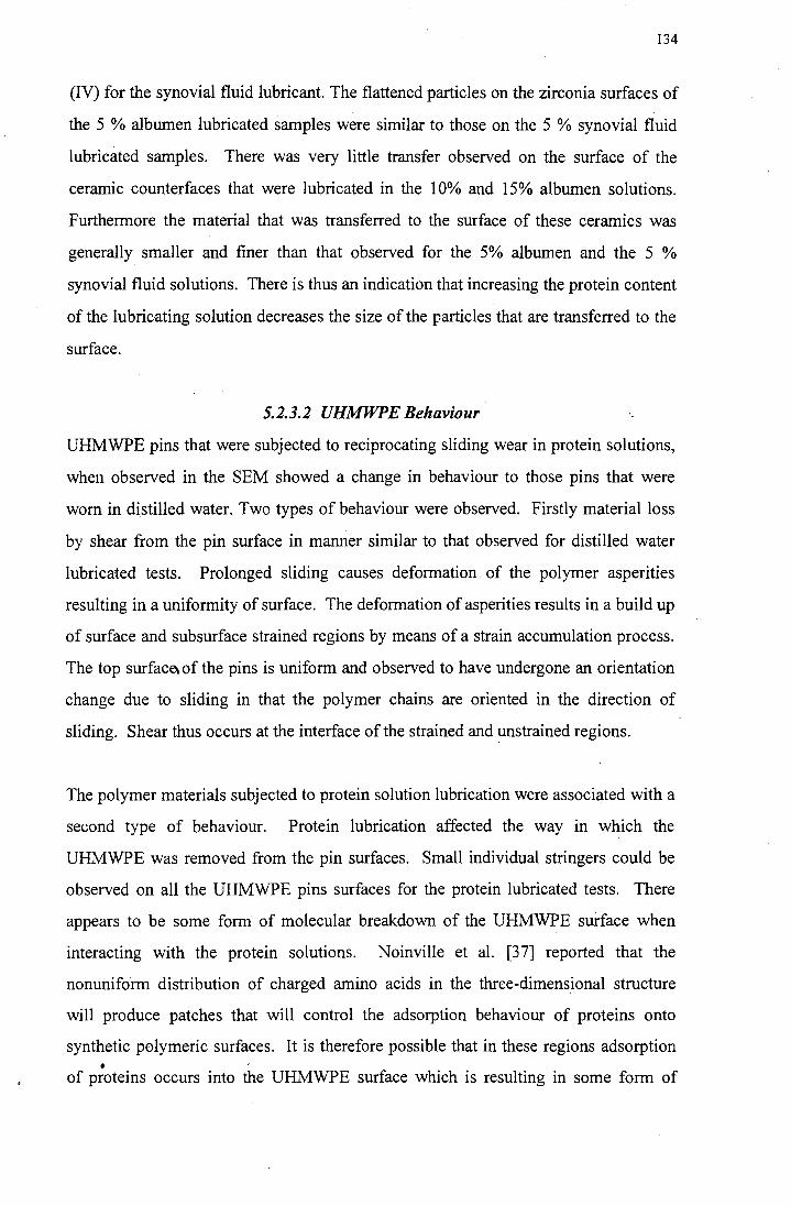
134
(IV) for the synovial fluid lubricant. The flattened particles on the zirconia surfaces of
the 5 % albumen lubricated samples were similar to those on the 5 % synovial fluid
lubricated samples. There was very little transfer observed on the surface of the
ceramic counterfaces that were lubricated in the 10% and 15% albumen solutions.
Furthermore the material that was transferred to the surface of these ceramics was
generally smaller and finer than that observed for the 5% albumen and the 5 %
synovial fluid solutions. There is thus an indication that increasing the protein content
of the lubricating solution decreases the size of the particles that are transferred to the
surface.
5.2.3.2 UHMWPE Behaviour
UHMWPE pins that were subjected to reciprocating sliding wear in protein solutions,
when observed in the SEM showed a change in behaviour to those pins that were
worn in distilled water. Two types of behaviour were observed. Firstly material loss
by shear from the pin surface in manner similar to that observed for distilled water
lubricated tests. Prolonged sliding causes deformation of the polymer asperities
resulting in a uniformity of surface. The deformation of asperities results in a build up
of surface and subsurface strained regions by means of a strain accumulation process.
The top surface. of the pins is uniform and observed to have undergone an orientation
change due to sliding in that the polymer chains are oriented in the direction of
sliding. Shear thus occurs at the interface of the strained and unstrained regions.
The polymer materials subjected to protein solution lubrication were associated with a
second type of behaviour. Protein lubrication affected the way in which the
UHMWPE was removed from the pin surfaces. Small individual stringers could be
observed on all the UHMWPE pins surfaces for the protein lubricated tests. There
appears to be some form of molecular breakdown of the UHMWPE surface when
interacting with the protein solutions. Noinville et al. (37] reported that the
nonuniform distribution of charged amino acids in the three-dimensional structure
will produce patches that will control the adsorption behaviour of proteins onto
synthetic polymeric surfaces. It is therefore possible that in these regions adsorption •
of proteins occurs into the UHMWPE surface which is resulting in some form of
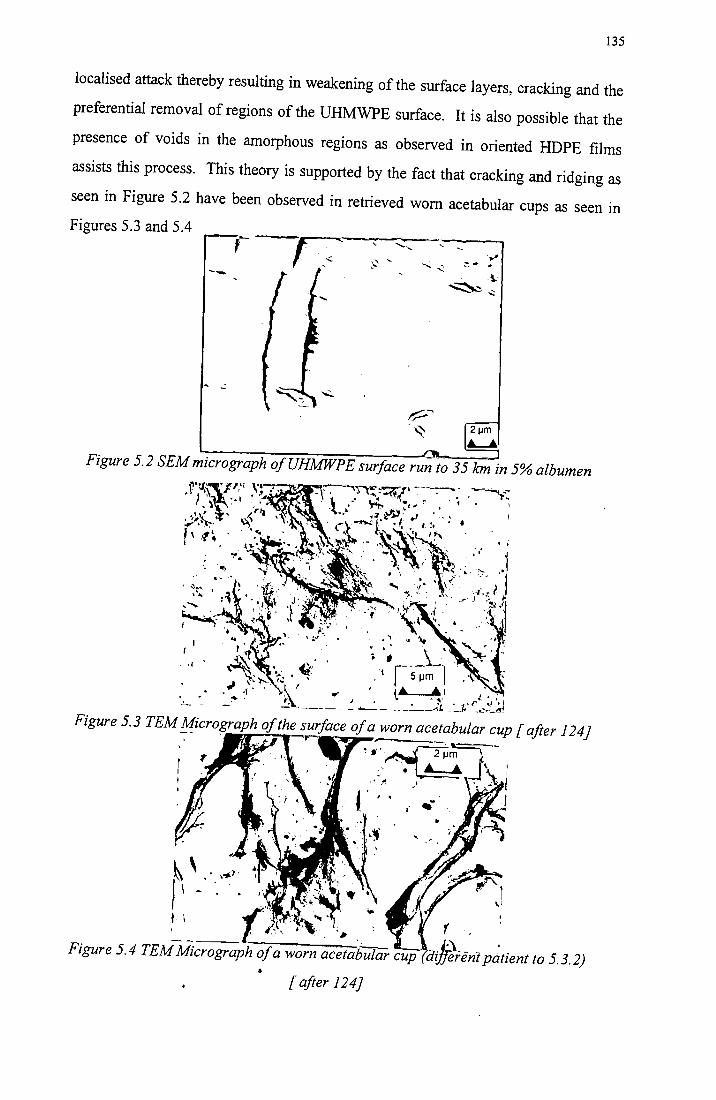
135
localised attack thereby resulting in weakening of the surface layers, cracking and the
preferential removal of regions of the UHMWPE surface. It is also possible that the
presence of voids in the amorphous regions as observed in oriented HDPE films
assists this process. This theory is supported by the fact that cracking and ridging as
seen in Figure 5.2 have been observed in retrieved worn acetabular cups as seen in
Figures 5.3 and 5.4 ,---
-~ ----
Figure 5.2 SEMmicrograph ofUHMWPE surface run to 35 km in 5% albumen
·I
Figure 5.3 TEM !!ficro¥raph of the_furface of a worn acetabular cup [after 124)
~~·.·~;;· .\ -· .. ~.~ \: .. -... ,. ·. ~. I
,· .. - ~ ..
'(
adfe\enl p~tient to 5.3.2) •
[after 124)
136
Another feature of the protein lubricated tests was the fact that the stringers and
sheared areas appear to remain adherent on the UHMWPE pin surface. Material
sheared from the pins run in distilled water was generally lost from the pin surfaces.
In addition to this, back transfer of polymer from the counterface surfaces to the pin
surfaces was observed only in the distilled water lubricated tests, It can therefore be
concluded that the presence of proteins causes an alteration in the way in which the
polymer wears. This occurs in two ways, by affecting the operative wear mechanisms
and by reducing the likelihood of a sheared polymer layer being removed
immediately. At increased sliding distances, the UHMWPE that sheared from the
surface of the polymer pins run in the protein solutions and readhered to the pin
surface is eventually removed as the strain accumulation process overcomes the
adhesive effect of the proteins and removes these sheared regions. Furthermore the
onset of cracking is observed at these increased sliding distances. This cracking is a
result of the polymer surface interacting with the proteins in solution and is most
prevalent at sliding distances in excess of 30km and the cracking effect is more
widespread for increasing albumen contents. Cracking of the polymer surface also
contributes to the increase in wear as it precedes shear from the pin surface. Thus for
increased cracking of the surface one would expect increased shear from the surface.
This would then be associated with increased polymer loss and an increase in wear
rates.
5.2.3.3 The Effect of Changing Counterface Roughness
The wear rates of the UHMWPE pins sliding against counterface surfaces with Ra
values of 0.06µm tested in the 10 and 15 % albumen solutions were low and remained
relatively constant. These wear rates were comparable with those obtained for
distilled water lubricated tests with counterface roughness values Ra of O.Olµm and
also with the final wear rates obtained for the UHMWPE pins tested in the albumen
solutions against counterfaces with surface roughness values of O.Olµm.
Increasing the counterface roughness for the distilled water , 10% and 15% albumen
lubricated wear tests increased the wear rates (given in mm3 /Nm) as follows:
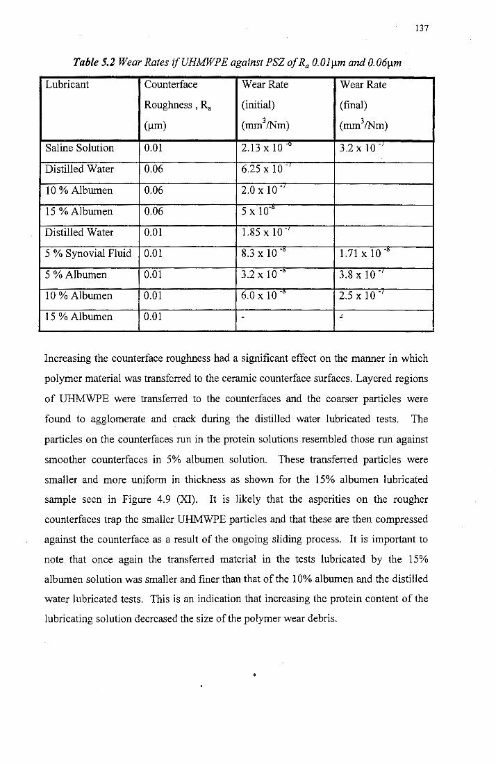
137
Table 5.2 Wear Rates ifUHMWPE against PSZ of Ra O.Olµm and 0.06µm
Lubricant Counterface Wear Rate Wear Rate
Roughness , Ra (initial) (final)
(µm) (mm3/Nm) (mm3/Nm)
Saline Solution 0.01 2.13 x 10 -o 3.2 x 10 -/
Distilled Water 0.06 6.25 x 10 .,
10 % Albumen 0.06 2.0 x 10 .,
15 %Albumen 0.06 5 x 10°6
Distilled Water 0.01 1.85 x 10 · 1
5 % Synovial Fluid 0.01 8.3 x 10 -o 1.71 x 10 °6
5 %Albumen 0.01 3.2 x 10 -o 3.8 x 10 -/
10 % Albumen 0.01 6.0 x 10 °6 2.5 x 10 -/
15 % Albumen 0.01 - ~
Increasing the counterface roughness had a significant effect on the manner in which
polymer material was transferred to the ceramic counterface surfaces. Layered regions
of UHMWPE were transferred to the counterfaces and the coarser particles were
found to agglomerate and crack during the distilled water lubricated tests. The
particles on the counterfaces run in the protein solutions resembled those run against
smoother counterfaces in 5% albumen solution. These transferred particles were
smaller and more uniform in thickness as shown for the 15% albumen lubricated
sample seen in Figure 4.9 (XI). It is likely that the asperities on the rougher
counterfaces trap the smaller UHMWPE particles and that these are then compressed
against the counterface as a result of the ongoing sliding process. It is important to
note that once again the transferred material in the tests lubricated by the 15%
albumen solution was smaller and finer than that of the 10% albumen and the distilled
water lubricated tests. This is an indication that increasing the protein content of the
lubricating solution decreased the size of the polymer wear debris.
138
5.3 Production of Wear Debris
Wear debris particles generally came in two forms, that of large particles in excess of
1 Oµm in size with visible surface corrugations, and that of smaller particles which
were generally spherical or oval in shape. It is likely that the larger particles are
directly lost by shear from the surface. The repeated reciprocating sliding against
these shear areas results in a push-pull action against the shearing material which
gives rise to the surface corrugations visible on the surface. The more prevalent
smaller particles were probably produced by two sources. The larger debris particles
may break down in the lubricating solution and the smaller sheared sections
(particularly those present in the protein lubricated tests) removed from the polymer
surface do not adhere to the counterface surfaces and are removed into the lubricating
solutions.
It seems probable that the lack of smaller spherical particles in the distilled water and
5% albumen solutions, when compared to those that were found in the solutions of
higher protein contents, can in part be attributed to the following: Firstly the nature of
the protein lubricant tends to assist the filtration of the smaller particles. This is
because viscous albumen, when filtered leaves a residue on the surface of the filter
paper. Increasing the albumen content of the lubricant effectively increases the
residue on the filter paper. This residue then acts to trap the smaller debris particles
on the surface of the filter paper. Furthermore the debris removed from the
UHMWPE surface in the 5% albumen lubricated test, was observed deposited on the
ceramic surface.
The debris from the distilled water lubricated tests tended to be the larger corrugated
particle type. This observation supports the view that different wear mechanisms
occur in the protein lubricated systems and that the protein affects the size of the wear
debris.
Generally the wear debris retrieved from the protein solutions was small with most
particles falling between 0 and 7 µm in dimension. This supports the findings of
Shanbhag et al. [3] for 11 failed Ti alloy THR's in which the polyethylene debris
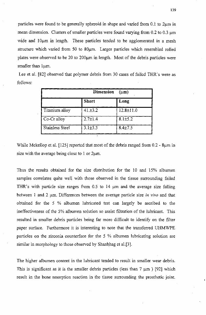
139
particles were found to be generally spheroid in shape and varied from 0.1 to 2µm in
mean dimension. Clusters of smaller particles were found varying from 0.2 to 0.3 µm
wide and lOµm in length. These particles tended to be agglomerated in a mesh
structure which varied from 50 to 80µm. Larger particles which resembled rolled
plates were observed to be 20 to 200µm in length. Most of the debris particles were
smaller than lµm.
Lee et al. [82] observed that polymer debris from 30 cases of failed THR's were as
follows:
Dimension (µm)
Short Long
Titanium alloy 41.±3.2 12.8±11.0
Co-Cr alloy 2.7±1.4 8.1±5.2
Stainless Steel 3.1±3.3 8.4±7.5
While Mckellop et al. (125] reported that most of the debris ranged from 0.2 - 8µm in
size with the average being close to 1 or 2µm.
Thus the results obtained for the size distribution for the 10 and 15% albumen
samples correlates quite well with those observed in the tissue surrounding failed
THR's with particle size ranges from 0.5 to 14 µm and the average size falling
between 1 and 2 µm. Differences between the average particle size in vivo and that
obtained for the 5 % albumen lubricated test can largely be ascribed to the
ineffectiveness of the 5% albumen solution so assist filtration of the lubricant. This
resulted in smaller debris particles being far more difficult to identify on the filter
paper surface. Furthermore it is interesting to note that the transferred UHMWPE
particles on the zirconia counterface for the 5 % albumen lubricating solution are
similar in morphology to those observed by Shanbhag et al.[3].
The higher albumen content in the lubricant tended to result in smaller wear debris.
This is significant as it is the smaller debris particles (less than 7 µm ) [92] which
result in the bone resorption reaction in the tissue surrounding the prosthetic joint.
140
Increasing the protein content of the lubricating solution results in a greater tendency
for molecular attack of the polymer surfaces, rather than material only being lost soley
by shear as has been observed for the distilled water lubricated tests. The low wear
rates for the increased protein content can be attributed to the fact that fibres, stringers
and sheared regions tend to readhere to the polymer pin rather than being lost. The
particles that are lost tend to be small (less than 2 µm) and large in number. It is clear
that the presence of a protein in the lubricating media does· affect the wear of
UHMWPE.
It would appear that albumen can be used as a substitute lubricating solution for the
investigation of prosthetic joint materials. The behaviour of the 'albumen was similar
to that of synovial fluid and the wear rates obtained using the albumen solution were
similar to that of the synovial fluid specimen. It should be noted that the albumen is
different in composition to the synovial fluid and therefore results should be treated
only as an approximation to the type of wear behaviour that can be expected in
prosthetic limbs. Furthermore the load was static, a situation which is unlikely in
vivo, and in this investigation the geometry of the hip joint has not been taken into
account in this investigation.
141
CHAPTER6
CONCLUSIONS
From the results obtained during this investigation the following general conclusions
can be drawn:
Water Lubricated Sliding Wear
1. The wear mechanism which dominates water lubricated sliding wear of
UHMWPE against a smooth ceramic surface is one of macroscopic asperity wear.
During this process asperities on the surface of the UHMWPE pins are initially
flattened during sliding resulting in a build up sub-surface deformation which is
1 followed by shear of the UHMWPE surface layers when the plastic limit of the
asperity peaks is reached.
2. The wear behaviour of UHMWPE sliding against ceramics is superior to that of
UHMWPE sliding against metals and this can be attributed to the superior
wettability of the ceramic surfaces which facilitates boundary lubrication.
3. The wear behaviour of zirconia is superior to that of alumina because the zirconia ,
counterface has a lower surface roughness than that of the alumina samples.
4. The friction coefficient of the UHMWPE when sliding against alumina and
zirconia materials decreases during sliding and stabilises at a low value. This
behaviour is due to the presence of transferred material on the ceramic surfaces.
5. Increasing the surface roughness of the ceramic counterfaces results in an increase.
in wear due to the larger asperities on the ceramic counterface acting as cutting
tools and removing larger amounts UHMWPE from the surface of the wear pin
Protein Lubricated Sliding Wear
1. Two mechanisms were found to contribute to polymer wear. Macroscopic
asperity wear which results in similar behaviour to that observed in the distilled
water lubricated wear, and that of chemical attack of the surface of the UHMWPE
142
which results in cracking and assists the removal of UHMWPE in the form of fine
stringers which are fibrous in structure
2. Increasing the content of albumen in the lubricating solution resulted in a decrease
in wear rate and an increase in the cracking of the pin surfaces. Increasing the
protein content in the lubricant resulted in less transfer of polymer to the
counterface surfaces. Furthermore, little UHMWPE debris was observed on the
counterfaces for the samples run in the 10% and 15% albumen lubricant against
counterfaces with Ra values of 0.0lµm.
3. Increasing the counterface roughness resulted in higher wear rates, and UHMPWE
particles were visible on the counterfaces for the 10% and 15% albumen
lubricated tests. This can be attributed to the fact that the increased asperity height
on the counterfaces causes UHMWPE debris to mechanically adhere to the
surfaces. The size of the debris particles visible on the counterface was seen to be
decreasing with increasing protein content.
Wear Debris
1. Increasing the protein content of the albumen solution leads to an decrease in the
size of the debris generated and this debris does not adhere readily to the ceramic
counterfaces for the 10% and 15% albumen solutions.
2. The difference in the average size and shape of the debris when comparing protein
lubrication to that of distilled water, can be explained by the difference in the way
in which polymer material is lost from the UHMWPE pin surfaces for the protein
lubricated and distilled water lubricated testing.
Albumen Lubrication
1. It can be concluded that albumen can be used as a substitute for synovial fluid as a
lubricating medium for the laboratory investigation of the behaviour of prosthetic
implant material. However further research is necessary to establish the
differences in behaviour of these two lubricants
143
APPENDIX A
OTHER MATERIALS USED FOR IMPLANTS
Prosthetic hip joints have been in use for about four decades. During this time
substantial changes have taken place with regard to the materials used. The
production of metal debris in metal on metal systems and the fairly high wear rates of
the metal-UHMWPE systems has led to the use of new materials and combinations
thereof. Alumina femoral heads articulating on UHMWPE acetabular cups show
better wear behaviour than the original stainless steel implant systems but the
production of UHMWPE wear debris is still a problem [75]. Alumina on alumina
systems have excellent wear and tribological characteristics, but their high stiffness
and brittle behaviour limits their usefulness [75]. Further advances have seen the
development of commercially pure titanium (Ti), Co-Cr-Mo alloys and Ti-6Al-4V
materials [75]. These systems are not perfect and exhibit one or more of the
following: stress corrosion, production of wear debris, stress shearing of cortical bone
and creep deformation. These all eventually result in the failure of the implant,
although it may take many years to fail.
It is because of the limitations of the present systems that new materials have been
developed. Many try to mimic the behaviour of cortical bone and most are ceramic
based.
A.1 Particle Filled Materials
Particles usually behave isotropically and as they have a random distribution in the
matrix of the particle filled materials, composites in this form usually behave
isotropically. Particle filled composites are considered to be the most significant of
the new composite materials and are beyond the experimental stages and are widely
used in practice. Generally matrices of polyethylene with either hyroxyapatite (HA)
or calcium phosphate fillers are used for bone substitution applications [121].
A.2 Fibre Reinforced Materials
Fibres in contrast to particles are anisotropic in nature and a composite will behave
anisotropically if fibres are oriented in its matrix. The degree to which the composite
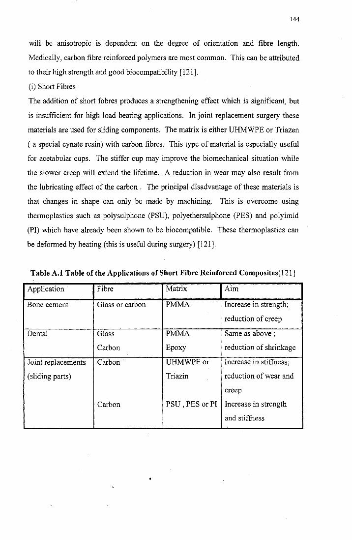
144
will be anisotropic is dependent on the degree of orientation and fibre length.
Medically, carbon fibre reinforced polymers are most common. This can be attributed
to their high strength and good biocompatibility [121].
(i) Short Fibres
The addition of short fobres produces a strengthening effect which is significant,. but
is insufficient for high load bearing applications. In joint replacement surgery these
materials are used for sliding components. The matrix is either UHMWPE or Triazen
( a special cynate resin) with carbon fibres. This type of material is especially useful
for acetabular cups. The stiffer cup may improve the biomechanical situation while
the slower creep will extend the lifetime. A reduction in wear may also result from
the lubricating effect of the carbon . The principal disadvantage of these materials is
that changes in shape can only be made by machining. This is overcome using
thermoplastics such as polysulphone (PSU), polyethersulphone (PES) and polyimid
(PI) which have already been shown to be biocompatible. These thermoplastics can
be deformed by heating (this is useful during surgery) [121].
Table A.1 Table of the Applications of Short Fibre Reinforced Composites[121]
Application Fibre Matrix Aim
Bone cement Glass or carbon PMMA Increase in strength;
reduction of creep
Dental Glass PMMA Same as above ;
Carbon Epoxy reduction of shrinkage
Joint replacements Carbon UHMWPEor Increase in stiffness;
(sliding parts) Triazin reduction of wear and
creep
Carbon PSU , PES or PI Increase in strength
and stiffness
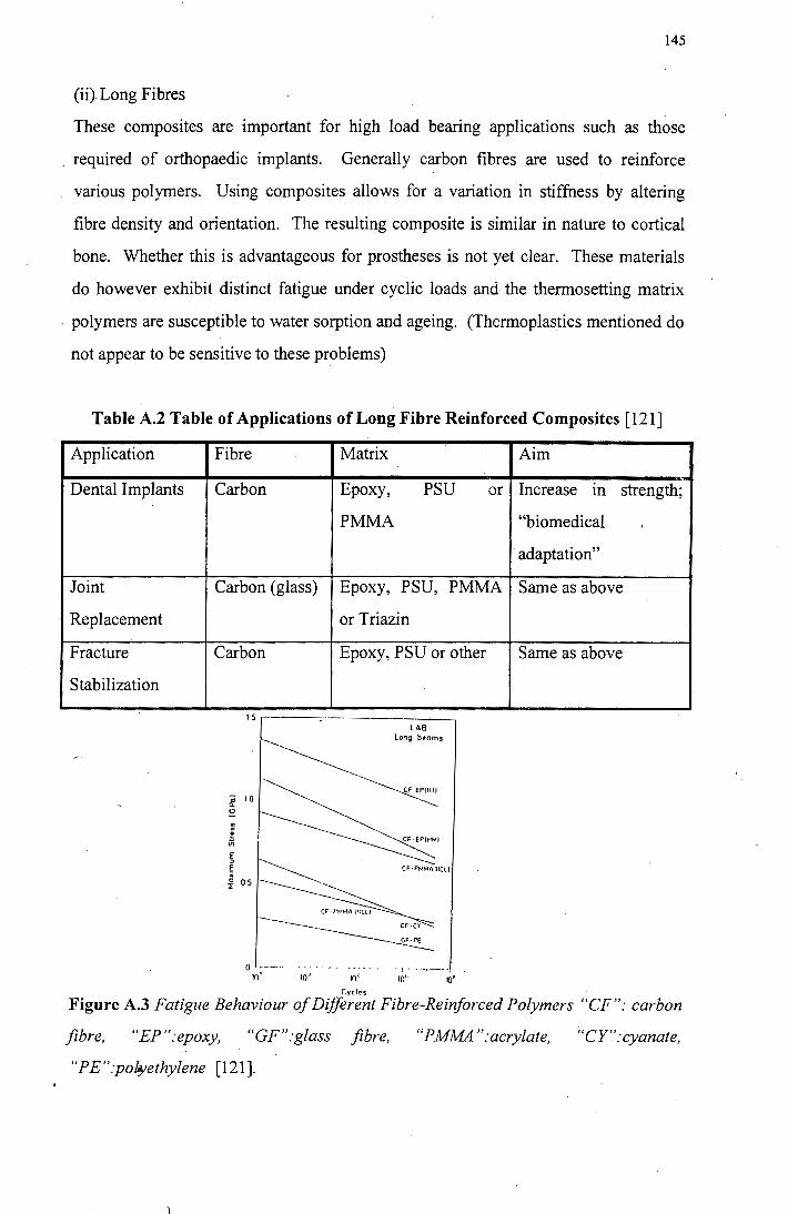
145
(ii) Long Fibres
These composites are important for high load bearing applications such as those
, required of orthopaedic implants, Generally carbon fibres are used to reinforce
various polymers. Using composites allows for a variation in stiffness by altering
fibre density and orientation. The resulting composite is similar in nature to cortical
bone. Whether this is advantageous for prostheses is not yet clear. These materials
do however exhibit distinct fatigue under cyclic loads and the thermosetting matrix
polymers are susceptible to water sorption and ageing. (Thermoplastics mentioned do
not appear to be sensitive to these problems)
Table A.2 Table of Applications of Long Fibre Reinforced Composites [121]
Application Fibre
Dental Implants Carbon
Joint Carbon (glass)
Replacement
Fracture Carbon
Stabilization
0 ____ ,,
10" . 10 1
Matrix
Epoxy, PSU or
PMMA
Epoxy, PSU, PMMA
or Triazin
Epoxy, PSU or other
10 1·
r.vcles
LAB long beams
Cf·EPfllll
···1. -·-·----10'· 10~
Aim
Increase m strength;
"biomedical
adaptation"
Same as above
Same as above
Figure A.3 Fatigue Behaviour of Different Fibre-Reinforced Polymers "CF": carbon
fibre, "EP":epoxy, "GF":glass fibre, "PMMA ":acrylate, ;'CY":cyanate,
"PE":pol"'ethylene [121].
146
A.3 Ceramic Fibre Reinforced Ceramics
At present only carbon-carbon materials are used in the medical field because of their
excellent biocompatibility. Other structural ceramics include alumina and silicon
carbide reinforced by carbon or silicon carbide fibres. This results in a less
anisotropic material than their carbon-carbon counterparts.
All these materials are still widely experimental and biostability and biocompatibility
as well as long term behaviour are not well established.
A.4 Hydroxyapatite-reinforced Polyethylene
None of the materials in currently in use for prosthetic joints mimic the behaviour of
cortical bone, as a result there are often problems with stress transfer across the tissue
implant interface. In the case of stiff materials such as alumina this often leads to
stress shielding of the cortical bone. The hydroxyapatite (HA) reinforced PE
(developed at Queen Mary College in collaboration with Brunnel University) seeks to
overcome this problem [63]. Mature cortical bone has a stiffness of 7-25GPa, a
critical stress intensity K1c of 2-12 MNm-312 and a critical strain intensity of 600-5
000 Jm-2. The bone is a biological composite of HA reinforced collagen (of which
HA constitutes the osteonal lamellae and provides a brittle ceramic filler - about 0.5
volume fraction) dispersed in a compliant matrix [63]. Polyethylene has been
extensively used as a biomaterial and has been established as biostable. HA is
calcined bone ash and as such is also biocompatible. No coupling agents are used and
thus this composite was expected to be'biostable. The HA-reinforced polyethylene
showed zero response to cytotoxicity tests in human embryonic lung tissue and,
implanted in adult rabbits for up to 6 months showed no adverse results. Furthermore
a secure bond between the natural tissue and the synthetic material was created and
this ensured a more stable implant. However further laboratory and clinical trails are
necessary to determine whether the HA coating will be replaced by bone or fibrous
tissue and if the enhancement coating (HA) may become a source of particulate debris
itself [63].
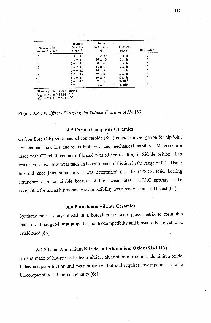
147
Young's Slrain I
llydroxynpatite Modulus lo Fraclure Fracture Volume Fraction (GNm- 2) (%) Mode Dioaclivity•
0 1.3 ± 0.2 > 90 Ductile x
10 1.4 ± 0.2 79 ± 10 Duclile ?
20 2.0 ± 0.1 50 ± 4 Duclile
25 2.5 ± 0.2. 43 ± 3 Duclile
30 3.0 ± 0.2 34 ± 5 Ductile ?
35 3.7 ± 0.4 32 ± 8 Duclile ?
40 4.4 ± 0.7 29 ± 5 Duclile J 45 5.9 ± 0.5 7 ± 3 Drillleb ?
50 7.7 ± 1.3 3 ± I Drilller J
"Bone apposition around implanl. ''Kie = 2.9 ± 0.3 MNm-v2
'1< 1c: = 2.4 ± 0.2 MNm .112
Figure A.4 The Effect of Varying the Volume Fraction of HA [63]
A.5 Carbon Composite Ceramics
Carbon fibre (CF) reinforced silicon carbide (SiC) is under investigation for hip joint
replacement materials due to its biological and mechanical stability. Materials are
made with CF reinforcement infiltrated with silicon resulting in SiC deposition. Lab
tests have shown low wear rates and coefficients of friction in the range of 0.1. Using
hip and knee joint simulators it was determined that the CFSiC-CFSiC bearing
components are unsuitable because of high wear rates. CFSiC appears to be
acceptable for use as hip stems. Biocompatibility has already been established [66].
A.6 Boroaluminosilicate Ceramics
Synthetic mica is crystallised in a boroaluminosilicate glass matrix to form this
material. It has good wear properties but biocompatibilty and biostability are yet to be
established [66].
A. 7 Silicon, Aluminium Nitride and Aluminium Oxide (SIALON)
This is made of hot-pressed silicon nitride, aluminium nitride and aluminium oxide.
It has adequate friction and wear properties but still requires investigation as to its
biocompatibilty and biofunctionality [66].
Appendix B
Amino Acids
148
Amino acids. are the monomer units of proteins, i.e. all proteins are made up of a
number of amino acids in varying combinations. The general structure of an amino
acid is that of an amino group and a carboxyl group bonded to the same carbon atom.
The nature of the side chains, referred to as R groups is the basis of the difference
between various amino acids. With the exception of glycine, amino acids can exist in
two forms. These are designated L and D and are stereoisomers i.e. non
superimosable mirror images. The amino acids found in proteins are all of the L
form. Amino acids are classified by the nature of the side chain, most importantly
whether the chains are polar or non-polar and the presence of an acidic or basic group
on the side chain [106]. Individual amino acids can be linked together by the
formation of covalent bonds. The bond is formed between the a.-carboxyl group of
one amino acid and the a-amino group of the next one; Water is eliminated during
this process and linked amino acid residues remain. Bonds formed in this way are
known as peptide bonds. In a protein many amino acids bond in this way to form a
polypeptide chain [106]. The formation of a peptide bond is shown in figure B2.
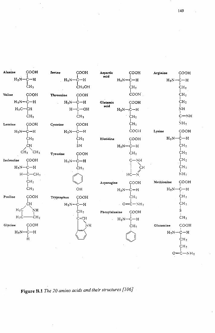
Alanine COOH I
H2N-C-H I CH3
Leucine COOH I
H2N-C-H I TH2
CH
/ "' CH3 CH3
Isoleucine COOH I
HoN-C-H - I H-C-CH:1
I CH·• I -CH3
Proline COOH I CH
/ "' HoC NH - I I
H~C--CH~
Glycine COOH I
H2N-C-H I H
Threonine COOH
Cysteine
I H2N-C-H
I H-C-OH
I CH3
COOH I
HoN-C-H - I
CHo I -SH
Tyrosine COOH I
HoN-C-H - I
¢' OH
Tryptophan COOH I
H2N-C-H I CHo I -C=CH 8H
Aspartic COOH acid I
H2N-C-H . I CH., I - . COOH.
Glutamic COOH acid I
H2N-:C-H I
. CHo I -CH·• I -COOH
Histidine COOH I
H2N-C-H I CHo I -
r3H HC-N
Asparagine COOH I
H2N-C-H I CH·> I -
O=C-NH:!
Phenylalanine COOH I
H2N-C-H I
cS
Figure B.1The20 amino acids and their structures [106]
149
Arginine COOH I
Lysine
H2N-C-H I CH. I -CH., I -CHo I -NH I C=NH I NH:!
COOH I
HoN-C-H - l
CH., I -CHo I -CHo r -CHo I -NH~
Methionine COOH I
HoN-C-H - I
CH., I -CHo I -s ! CH3
Glutamine COOH I
HoN-C-H - I
CHo I -CHo I -
O=C-NH~
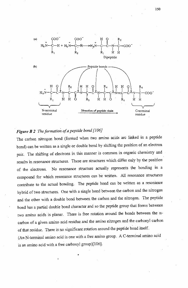
(a) COO COO- H 0 R + I + I + I II I
2
H3N-C,-H + H3N-C-:-R~H3N-C-C-N-c-coo-I • I I I
(b)
R1 R2 R 1 H H
N-terminal residue
Di peptide
Direction of peptide chain
Figure B 2 TheformatiOn ofapeptide bond [106}
'--y-J C-terrninal residue
150
The carbon nitrogen bond (formed when two amino acids are linked in a peptide
bond) can be written as a single or double bond by shifting the position of an electron
pair. The shifting of electrons in this manner is common in organic chemistry and
results in resonance structures. These are structures which differ only by the position
of the electrons. No resonance structure actually represents the bonding in a
compound for which resonance structures can be written. All resonance structures
contribute to the actual bonding. The peptide bond can be written as a resonance
hybrid of two structures. One with a single bond between the carbon and the nitrogen
and the other with a double bond between the carbon and the nitrogen. The peptide
bond has a partial double bond character and so the peptide group that forms between
two amino acids is planar. There is free rotation around the bonds between the a
carbon of a given amino acid residue and the amino nitrogen and the carbonyl carbon
of that residue. There is no significant rotation around the peptide bond itself.
(An N-terminal amino acid is one with a free amino group. AC-terminal amino acid
is an amino acid with a free carboxyl group)[106].
APPENDIXC
Polysaccharides
151
The simplest carbohydrates are known as monosaccharides. Monosaccharides are
compounds that contain a single carbonyl group and two or more hydroxyl groups.
Monosaccharides can undergo various reactions which include oxidation and
esterification. The most important reaction is that of the formation of glycosidic
linkages which result in oligosaccharides and polysaccharides. Monosaccharides are
polyhydroxyaldehydes or polyhydroxyketones. It is possible for a sugar hydroxyl
bond (ROH) to react with another hydroxyl (R'OH) to form an ester linkage (R' -O
R). This type of reaction frequently involves the -OH group bonded to the anomeric
carbon of the sugar in its cyclic form. (Anomeric carbon is the carbonyl carbon of the
open chain form of the sugar, it is the carbon that becomes a chiral centre in the cyclic
form for monosaccharides). This newly formed bond is known as a glycosidic bond.
Polysaccharides that occur in organisms are usually a combination of several types of
monosaccharides. A polymer consisting of only one type of monosaccharide is
known as a homopolysaccharide, while a polymer consisting of more than one type of
monosaccharide is a heteropolysaccharide. Glucose is the most common monomer.
There are usually only two· types of molecules in a repeating sequence.
Hyaluronic acid is a heteropolysaccharide found in the connective tissue of animals.
As a result of its highly viscous gelatinous consistency, it is known as a
mucopolysaccharide. It is a polymer of two repeating units of two glucose
derivatives, N-acetylglucosamine and glucuronic acid. Glucuronic acid is derived
from glucose by the oxidation of the hydroxyl group at the C-6 carbon of glucose.
The monomer units are linked together by alternating p (1-) 3) and p (1 -) 4)
glycosidic bonds. Hyaluronic acid occurs in synovial fluid which is the lubricating
fluid of joints [106].
APPENDIXD
Glycoproteins
152
Glycoproteins contain carbohydrate residues in addition to the polypeptide chain.
Important examples of glycoproteins are involved in immune response. Antibodies
which bind to an immobilise antigens (the substance attacking the organism) are
glycoproteins. Carbohydrates play an important role as antigenic determinants, which
are the portions of the antigenic molecule that antibodies recognise and to which they
bind (106].
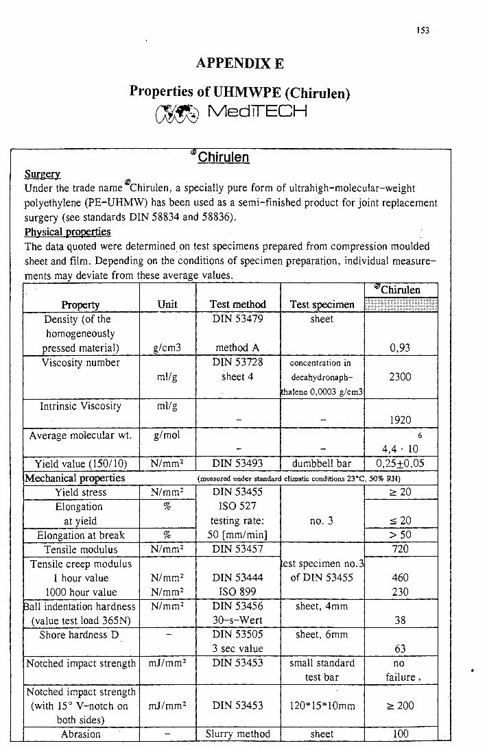
APPENDIXE
Properties of UHMWPE (Chirulen)
(Jt1~ MedlfECH
®Chirulen
153
Surg~ Under the trade name ®chirulen, a specially pure form of ultrahigh-molecular-weight polyethylene (PE-UHMW) has been used as a semi-finished product for joint replacement surgery (see standards DIN 58834 and 58836). Physical Qro~rties The data quoted were determined on test specimens prepared from compression moulded sheet and film. Depending on the conditions of specimen preparation, individual measure-ments may deviate from these average values.
Vil Chirulen Property Unit Test method Test specimen : .i· :: . ::i: :::.'
Density (of the DIN 53479 sheet homogeneously
pressed material) g/cm3 method A 0,93 Viscosity number DIN 53728 concentration in
ml/g sheet 4 decahydronaph- 2300 thalene 0,0003 g/cm3
Intrinsic Viscosity ml/g - - 1920
Average molecular wt. g/mol 6
- - 4,4. 10
Yield value (150/ 10) N/mm2 DIN 53493 dumbbell bar 0,25±0,05 Mechanical properties (measured under standard climatic conditions 23°C, 50% RH)
Yield stress N/mm2 DIN 53455 ~ 20 Elongation % ISO 527
at yield testing rate: no. 3 ::::; 20
Elongation at break % 50 [mm/min] > 50 Tensile modulus N/mm2 DIN 53457 720
Tensile creep modulus ~est specimen no.3 1 hour value N/mm2 DIN 53444 of DIN 53455 460
1000 hour value N/mm2 ISO 899 230 Ball indentation hardness N/mm2 DIN 53456 sheet, 4mm
(value test load 365N) 30-s-Wert 38 Shore hardness D - DIN 53505 sheet, 6mm
3 sec value 63 Notched impact strength mJ/mm2 DIN 53453 small standard no
test bar failure. Notched impact strength (with 15° V-notch on mJ/mm2 DIN 53453 120*15*10mm ~ 200
both sides) Abrasion - Slurry method sheet 100
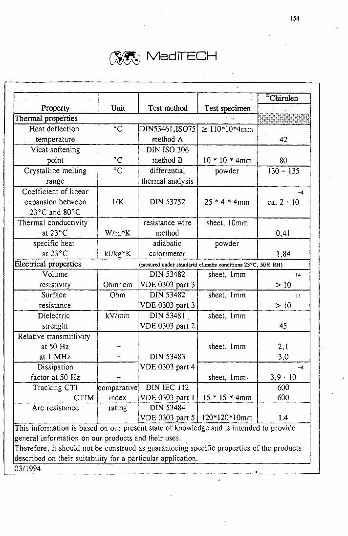
154
~ MedTrECH
llJ/Chirulen Property Unit Test method · Test specimen
Therrtial properties .. : ··-Heat deflection oc DIN5346 l ,IS075 ;::::: 110* l0*4mm temperature method A 42
Vicat softening DIN ISO 306 point oc method B 10 * 10 * 4mm 80
Crystalline melting oc differential powder 130 - 135 range thermal analysis
Coefficient of linear -4
expansion between l/K DIN 53752 25 * 4 * 4mm ca. 2 · 10 23°C and 80°C
Thermal conductivity resistance wire sheet, lOmm at 23°C W/m*K method 0,41
specific heat adiabatic powder at23°C kJ/kg*K calorimeter 1,84
Electrical properties (mesured undet standartd climatic conditions 23°C, 50% RH)
Volume DIN 53482 sheet, Imm· 14
resistivity Ohm*cm VDE 0303 part 3 > 10 Surface Ohm D~N 53482 sheet, lmm II
resistance VDE 0303 part 3 > 10 Dielectric kV/mm DIN 53481 sheet, Imm
strenght VDE 0303 part 2 45 Relative transmittivity
at 50 Hz - sheet, lmm 2, 1 at i·MHz - DIN 53483 3,0
Dissipation VDE 0303 part 4 -4
factor at 50 Hz - sheet, lmm. 3,9. 10 Tracking CTI comparative DIN IEC 112 600
CTIM index VDE 0303 part 1 15*15*4mm 600 Arc resistance rating DIN 53484
VDE 0303 part 5 120* 120* lOmm L4 This information is based on our present state of kriowledge and is intended to provide general information on our products and their uses. Therefore, it should not be construed as guaranteeing specific properties of the products described on their suitability for a particular application. 03/1994
155
REFERENCES
1. Cooper J R, Dowson D, Fisher J, "Macroscopic and Microscopic Wear
Mechanisms in Ultrahigh Molecular Weight Polyethylene", Wear, 162-164, 1993,
p 378-384
2. Saikko V, "Wear of Polyethylene Acetabular Cups against Zirconia Femoral
Heads Studied in a Hip Joint Simulator", Wear, 176, 1994, p 207-212
3. Shanbhag AS, Jacobs J, Glant T, Gilbert J L, Black J, Galante J 0, "Composition
and Morphology of Wear Debris in Failed Uncemented Total Hip Replacement",
J Bone & Joint Surg, 76B, 1994, p 60-67
4. Willert H G, Semlitch M, "Reactions of the Articular Capsule to Wear Products
of Artificial Joint Prostheses", J Biomed Res., ll, 1977, p 157-164
5. Goldring SR, Schiller AL, Roelke Met al, "The Synovial-like Membrane at the
Bone-Cement Interface in Loose Total Hip Replacements and its Proposed Role in
Bone Lysis", J Bone & Joint Surg [Am], 65-A, 1983, p 574-584
6. Maloney J, Jasty M, Harris W H, Galante J 0, Callaghan J J, "Endosteal Erosion
in Association with Stable Uncemented Femoral Components", J Bone & Joint
Surg [Am], 72-A, 1990, p 1025-1034
7. Howie D W, Vernon-Roberts B, Oakeshott RD, Manthey B, "A Rat Model of
Resorption of Bone at the Cement-Bone Interface in the Presence of Polyethylene
Wear Particles", J Bone & Joint Surg [Am], 70-A, 1988, p 257-263
8. Goodman S B, Fomasier VL , Lee J, Kei J, "The Histological effects of the
Implantation of Different Sizes of Polyethylene Particles in the Rabbit Tibia", J
Biomed. Mater Res., 24, 1990, p 517-524
9. Clarke I C (chairperson), Dorlot J-M, Graham J, Levine D J, Oonishi H, Rieu J,
Rigney D, Schwartz G, Sedel L, Toni A, Zitelli J, "Biomechanical Stability and
Design : Wear", Position paper 8, Annals N. Y Academy of Sciences, 1988, p
292-296
10. Langkamer VG, Case C P, Heap P, Taylor A, Collins C, Pearse M, Solomon L,
"Systematic Distribution of Wear Debris After Hip Replacement- A Cause for
Concern?", J Bone & Joint Surg., 74-B, No 6, Nov. 1992, p 831-839
156
11. Hernandez J B, Keating EM, Faris PM, Meding J B, Ritter MA, "Polyethylene
Wear in Uncemented Acetabular Components'', J Bone & Joint Surg., 76-B, No 2,
March 1994, p 263-266
12. Fisher J, Dowson D, Cooper JR, Jin Z M, Wroblewski B M, "The Failure and
Wear of UHMWPE in Artificial'Joints", J Bone & Joint Surg., 75-~, 1993 : Sup
III
13. Malcolm A J, "Pathology of Longstanding Cemented Total Hip Replacements in
Charnely 's Cases" , J Bone & Joint Surg., 70-B, 1988, p 153
14. McCrum NG, Buckley C P, Bucknall CB, Principles of Polymer Engineering,
Oxford Sci. Publ, 1988
15. Crow JM G, Polymers: Chemistry and Physics of Modern Materials, 2nd edn,
Blackie & Son Ltd. Chapman and Hall Inc., NY, 1991.
16. Flory P J, Yoon D Y, "Molecular Morphology in Semicrystalline Polymers",
Nature, 272, 16 March, 1978, p 226-229
17. Meares P, Polymers: Structure and Bulk Properties, D Van Nostrand Company
Ltd., London 1965
18. Fischer E W, "Neutron-Scattering Studies on the Crystallization of Polymers"
Polym. J, 11, 1985, p 307-320
19. McCrum N G, Read B E, Williams G, Anelastic and Dielectric Effects in
Polymer Solids, Wiley, N.Y., 1967
20. Vanderhart D L, "Natural-Abundance C-13-C-13 Spin Exchange in Rigid
Crystalline Organic Solids" J Magn Reson., 72, 1987, p 13-47
21. Syi J-L, Mansfield M L, "Solition Model of the Crystalline-Alpha Relaxation"
Polymer, 29, 1988, p 987-997
22. Schmidt-Rohr K, Spies H W, "Chain Diffusion between Crystalline and
Amorphous Regions in Polyethylene detected by 13C NMR '', Macromolecules, 24,
1991, p 5288-5293
23. Petermann I, Riek U, "On the Plastic Deformation of Fibre Self-Reinforced
Polymers", J Mat Sci, 22, 1987, p 1120-1126
24. Kestenbach H J, Petermann 0, "Micellular Morphology and its Plastic
Deformation Behaviour in Ultra-high Molecular Weight Polyethylene", J Mat Sci,
29, 1994, p 6539-6542
157
25. Cho Myung H, Sadao H, Thein K, "Crystal Twinning in Simultaneous Biaxial
Stretching of Gelation-Crystallised Ultra-high Molecular Weight Polyethylene", J
Mat Sci,, 26, 1991, p 2507-2513
26. Suehiro K, Terashima T, Takayanagi M, "Change of Mosaic Block Size of Bulk
Polyethylene in Drawing Processes", J Mat Sci.,..2, 1974, p 1563-1568
27. Pigeon M, Prud'homme R E, Pezolet M, "Characterisation of Molecular
Orientation in Polyethylene by Raman Spectroscopy", Macromolecules, 24, 1991,
p 5687-5694
28. Peterlin A, "Structure of Drawn Polymers'', Technical Report AFML-TR-67-6 ,
US Air Force Materials Lab, Wright-Patterson, AFB, Ohio 1966
29. Zurn Gahr K H, Microstructure and Wear of Materials, Tribology Series, V 10,
Elsevier, Amsterdam, 1987
30. Rose W, Meurer Ch, "Multiple Kinks in Lamellar Linear Polyethylene" ,J Mat
Sci, 16(4), 1981, p 883-888
31. Pietralla M, "Twinning as a Fundamental Process in Polymer Crystal
Orientation", Int J Polymeric Mater., 22, 1993, p 185-190
32. Marikhin V A, Myasinikova L P, Supermolecular Structure of Polymers,
Kiminiya, Leningrad, 1978.(in Russian)
33. Guttman C M, DiMarzio E A, "Polyethylene-like polymer between two plates
Connection to Gamblers Ruin Problem", Macromolecules, 15(2), 1982, p 525
34. Elyashevich G K, Karpov E A, Lavrentiev KV, Poddubny V I, Genina M A,
Zabashta Y F, "Changes in the Amorphous Phase of Polyethylene upon High
Extension'', Int J Polymeric Mater., 22, 1993, p 191-199
35. Ziatsev M G, Yaryukin S E, "Thermodynamic Prediction of Molecular
Morphology Parameters of Amorphous Regions of Worn Polymers", Int J
Polymeric Mater., 22, 1993, p 33-40
36. Brydson J A, Plastics Materials, 4th edition, Butterworth Scientific, 1982
37. Noinville V, Vidal-Madjar C, Sebille B, "Modelling of Protein Adsorption on
Polymer Surfaces. Computation of Adsorption Potential", J Phys Chem, 22,
1995, p 1516-1522
38. Cherry B W, Polymer Surfaces, Cahn R W, Thompson M W, Ward I M (eds),
Cambridge University Press 1981
158
39. Tabor D, "Friction-The Present State of Our Understanding", J Lub Tech, ASME
Trans, 1Q1, 1981, p 169-179
40. Halling J, Introduction to Tribology, Wykenham Publ., London, 1976
41. Czichos H, "Introduction to Friction and Wear", in Friction and Wear of
Polymer Composites , K Friedrich ( ed), Chl, l, Composite Materials Series,
Amsterdam, Elsevier, 1986, p t-23
42. Benabdallah S H, "Shear Strength Resulting from Static Friction of Some
Thermoplastics", J Mat Sci, 28, 1993, p 3149-3154
43. Marcus K, Micromechanisms of Polymer Sliding Wear, Thesis
44. J K Lancaster, "Material-specific Wear Mechanisms: Relevance to Wear
Modelling", Wear, 141, 1990, p 159-183
45. Tabor D, "The Wear of Non-Metallic Materials: a.Brief Review", from The Wear
df Non-Metallic Materials, Proceedings of.the 3rd Leeds-Lyon Symposium on
Tribology, Sept. 1976, Mech. Eng.Puhl, p 3-8
46. Gong D, Xue Q, Wang H, "Physical Models of Adhesive Wear of
Polytetrqfiuoroethylene and its Composites", Wear, 14 7, 1991,p 9-24
47. Buckley D H, Surface Effects in Adhesion, Friction, Wear and Lubrication,
Tribology Series 5, Elsevier, N.Y., 1981
48. Briscoe BJ, "Wear of Polymers: An Essay on Fundamental Aspects", Trib Int.,
14, Aug 1981, p 231-234
49. Zurn Gahr K H, Microstructure and Wear of Materials, Tribology Series, V 10,
Elsevier, Amsterdam, 1989
50. Lancaster J K, "Abrasive Wear of Polymers", Wear, 14, 1969, p 223-239
51. Rose RM, Cimino WR, Ellis E, Grugnola AN, "Exploratory Investigation on
the Structure Dependence of the Wear Resistance of Polyethylene", Wear, 77,
1982, p 89-104
52. Jones W R (jr.), Hady W F, Grugnola A N, "Effect of y - Irradiation on the
Friction and Wear of Ultra-high Molecular Weight Polyethylene", Wear, 70,
1981, p 77-92
53. Wineman A, "Mechanical Response of Linear Viscoelastic Solids", MRS
Bulletin, May 1991, p 19-23
, I
159
54. McLaren K G, Tabor D, "Viscoelastic Properties and the Friction of Solids.
Friction of Polymers: Influence of Speed and Temperature'', Nature, 121, 1963, p
856-858
55. Ludema K C, Tabor D, "The Friction and Viscoelastic Properties of Polymeric
Solids", Wear, 2., 1966, p 329-348
56. Briscoe B J, Tabor D, "Friction and Wear of Polymers : The Role of Mechanical
Properties", Br Polym Journal, 10, March 1978, p 74-78
57. Bahadur S, Stiglich J, "The Wear of High-Density Polyethylene Sliding Against
Stainless Steel Surfaces", Wear, 68, 1981, p 85-95
58. Dowson D, Harding R T, "The Wear Characteristics of Ultrahigh Molecular
Weight Polyethylene against a High Density Alumina Ceramic under Wet
(distilled water) and Dry Conditions", Wear, 75, 1982, p 313-331
59. Hollander A E, Lancaster J K, "An Application of Topographical Analysis to the
Wear of Polymers", Wear, 25, No 2, 1973, p 155-170
60. Rose R M, Goldfield H V, "On the Pressure Dependence of the Wear of
Ultrahigh Molecular Weight Polyethylene", Wear, .22, 1983, p 99-111
61. Rose R M, Crugnola A, Ries M, Cimino R, Radin Paul, Radin E L, "On the
Origins of High In Vivo Wear Rates in Polyethylene Components of Total Joint
Prostheses", Clin Orthop., 145, 1979, p 277-289
62. Komoto T, Tanaka K, "Morphological Study of the Wear of Crystalline Polymers
I: High Density Polyethylene'', Wear, 75, 1992, p 173-182
63. Bonfield W, "Hydroxyapatite-Reinforced Polyethylene as an Analagous Material
for Bone Replacement", Annals NY Academy of Sciences, 1988, p 173-177
64. Callaghan J, "Results of Primary Total Hip Arthroplasty in Young Patients", J
Bone & Joint Surg., 75-A, No 11, Nov 1993, p 1728~1734
65. Biomedical Stability and Design - Strength, Annals N Y Academy of Sciences,
Position Paper 7, 1988, p 287-291
66. Christel P, Meunier A, Dorlot J-M, Crolet J-M, Witvoet J, Sedel L, Boutin P,
"Biomechanical Stability and Design of Ceramic Implants for Orthopaedic
Surgery", Annals NY Academy of Sciences, 1988, p 234-255
67. Lewis G, Daigle K, "Electrochemical Behaviour of Ti-6Al-4V Alloy in Static
Biosimulating Conditions", Jnl Applied Biomaterials, 1_, 1993, p 37-45
160
68. Agins H J, Alcock N W, Bansal M et al, "Metallic Wear in Failed Titanium-Alloy
Total Hip Replacements : A Histological and Quantitative Analysis'', J Bone &
Joint Surg [Am], 70-A, 1988, p 347-356
69. Lombardi A, Mallory TH , Vaughan B K, Drouillard P, "Aseptic Loosening in
Total Hip Arthroplasty Secondary to Osteolysis Induced by Wear Debris from
Titanium Alloy Modular Femoral Heads", J Bone & Joint Surg [Am], 71-A, 1989,
p 1337-1342
70. Robinson RP, Lovell T P, Green TM, Bailey GA, "Early Femoral Component
Loosening in DF-80 Total Hip Arthroplasty", J Arthroplasty, 1989, ~, p 55-64
71. Black J, Sherk H, Bonino J et al, "Metallosis Associated with a Stable Titanium
Alloy Femoral Component in Total Hip Replacement: A Case Report", J bone &
Joint Surg [Am], 1990, 72-A, p 126-130
72. Witt JD, Swann M, "Metal Wear and Tissue Response in Failed Titanium Alloy
Total Hip Replacements", J Bone & Joint Surg. [Br], 1991, 73-B, p 559-563
73. Boehler M, Nahr K, Plank H(Jr), Walter A, Salzer M, Schreiber V, "Long-term
Results of Uncemented Alumina Acetabular Implants", J Bone & Joint Surg [Br],
76-B, 1994, p 53-59
74. Sedel L, "Ceramic Hips", J Bone & Joint Surg [Br], 74-B, 1992, 331-332
75. C Clarke (chairperson), "Biomechanical Stability and Design: Wear", Position
Paper 8, Annals NY Academy of Sciences, 1988, p 292-296
76. Katz J L (chairperson), "Biomechanical Stability and Design Stiffness and
Remodelling", Annals NY Academy of Sciences, 283-286
77. Cook S D, Barrat R L, Clemow A J T, "Corrosion and Wear at the Modular
Interface of Uncemented Femoral Stems", J Bone & Joint Surg [Br], 76-B, 1994,
p 68-72
78. Wang A, Sun DC, Stark C, Dumbleton J H, "Wear Mechanisms of UHMWPE in
Total Joint Replacements", Wear, 181-183, 1995, p 245-249
79. Feller W, An Introduction to Probability Theories and Its Applications, l,
WileyN.Y., 1968,p 175-190
80. Lennox D W, Schofield B H, McDonald D F, Riley L H, "Aseptic Loosening in
Various Prostheses", Clin Orthop & Rel Res, 225, 1987, p 171-191
161
81. Maloney W J, Peters P, Engh CA, Chandler H, "Severe Osteolysis of the Pelvis in
Association with Acetabular Replacement without Cement'', J Bone & Joint Surg,
75-A, No 11, Nov 1993, p 1627-1635
82. Lee JM, Salvati EA, Betts F, DiCarlo E F, Dory S B, Bullough P G, "Size of
Metallic and Polyethylene Debris in failed Total Hip Replacements", J Bone &
Joint Surg, 74-B, 1992, p 380-384 !
83. Escalas F, Galante J, Rostoker W, "Biocompatibility of Materials for Total Joint
Replacement", J Biomed. Res., 10, 1976, p 175-195
84. Johansen N A, Bullough P G, Wilson P D Jr, Salvati E A, Ranawat C S, "The
Microscopic Anatomy of the Bone-Cement Interface in Failed Total Hip
Arthroplasties", Clin. Orthop., 218, 1987, p 123-135
85. Cohen J, "Assay of Foreign Body Reaction", J Bone & Joint Surg [Am], 41-A,
1976, p 391-397
86. Matlaga B F, Yasenchak L P , Salthouse T B, "Tissue Response to Implanted
Polymers: the Significance of Sample Shape", J Biomed Mater. Res., 1.D.; 1976, p
391-397
87. Salthouse T N, "Some Aspects of Macrophage Behaviour at the Implant
Interface", J Biomed Mater Res, 18_, 1984, p 395-401
88. Isaac G H, Atkinson J R, Dowson D, Wroblewski B M, "The Role of Cement in
the Long-term Performance and Premature Failure of Charnley Low Friction
Arthroplasties ", Eng Med, 12(1), 1986, p 19-22
89. Maloney W J, Jasy M, Harris W, Galante J 0, Callaghan J J, "Endosteal Erosion
in Association with Stable Uncemented Femoral Components", J Bone & Joint
Surg., 75-A, Aug 1990, p 1025-1034 (
90. Maloney W J, Peters P, Eng CA, Chandler H, "Severe Osteolysis of the Pelvis in
Association with Acetabular Replacement without Cement", J Bone & Joint Surg.,
75-A, No-11, Nov 1993, p 1627-1635
91. Schmalried T P, Jasty M, Harris W H, "Periprosthetic Bone Loss in Total Hip
Arthroplasty. Polyethylene Wear_ Debris and the Concept of Effective Joint
Space", J Bone & Joint Surg., 74-A, July 1992, p 849-863
92. Robert J, Quastel J H, "Particles Uptake by Polymorphonuclear Leucocytes and
the Ehrlich Ascites-Carcinoma Cells", Biochem J, 1963, 89, p 150-156
162
93. Giant TT, Jacobs J J, Monlar G, et al, "Bone Resorption Activity of Particulate
Simulated Macrophages", J Miner Res., 1993, .8., p 1071-1079
94. Glant T T, Jacobs J J, "Response of 3 Murine Macrophage Populations to
Particulate Debris- Bone-Resorption Reaction Organ Cultures'', J Orthop. Res.,
Uill, 1994, p 720-731 J
95. Shanbag AS, Jacobs J J, Black J, Galante J 0, Glant TT, "Macrophage/Particle
Interactions : The Effect of the Size, Composition and Surface Area", J Biomed
Mater. Res., 1994, 2-8... p 81-90
96. Tabor D, The Role of Surface and Intermolecular Forces in Thin FHm
Lubrication. Microscopic Aspects of Adhesion and Lubrication, J M Georges
( ed), Amsterdam, Elsevier, Tribology Series, 1, 1982, p 651-659
97. Avitzur B, "Boundary and Hydrodynamic Lubrication", Wear, lli, 1990, p 46-
76
98. Halling J (ed), Principle of Tribology, McMillan Press Ltd, London, 1983
99. Lubrication Theory and Its Applications, BP Trading Ltd, London, 1969
100.Meldahl A, "Contribution to the Theory of the Lubrication of Gears and the
Stressing of the Lubricating Flanks of Gear Teeth", Brown Boveri Rev., 001),
1941, p 374
101.Dowson D, "Elastohydrodynamic and Micro-elastohydrodynamic Lubrication",
Wear, 190, 1995, p 125-138
102.Kapsa P, Martin J, "Boundary Lubricant Films: a review", Trib Int., 00), 1982
103.Swanson S A V, "Mechanical Breakdown of Articular Cartilage in
Osteoarthrosis", Paper V(l), from The Wear of Non-Metallic Materials,
Proceedings of the 3rd Leeds-Lyon Symposium on Tribology, Sept 1976, Mech
Eng Publ. Ltd., 1978, p 109-112
104.Unsworth A, Dowson D, Wright V, Koshal D, "The Frictional Behaviour of
Human Synovial Joints part 2: Artificial Joints", J Lubr. Technol., July 1975, p
377-382
105.Unsworth A, "The Effects of Lubrication in Hip Joint Prostheses" Phys. Med.
Biol., 23, 1978, p 253-268
106.Campbell MK (ed), Biochemistry, Saunders College Publishing, USA, 1991
163
107.Florkin M, Stoltz E (eds), Comprehensive Biochemistry Proteins (part 1), 1
Elsevier, 1963
108.Nigam KM, Bujurke NM, Singh MP, Manohair K, "Second-grade Fluid Film
Lubrication in Hertzian Contacts with Reference to Synovial Joints", Wear, 84,
1983, p 261-274
109.Sinha P, Singh C, Prasad KR, "Lubrication of Human Joints, a Microcontinuum
Approach", Wear, 80, 1982, p 159-181
110.Prakash J, Sinha P, "Lubrication Theory of Micropolar Fluids and its Application
to a Journal Bearing", Int. J Eng Sci., ll, 1975, p 217-232
111.Linn F C, Radin E L, "Lubrication of Animal Joints !IL the Effect of Certain
Chemical Alteration of the Cartilage and the Lubricant", Arth. Rheum., II, 1968,
p 674-682
112.0'Kelly J, Unsworth A, Dowson D, Hall DA, Wright V, "A Study of the Role of
Synovial Fluid and its Constituents in the Friction and Lubrication of Human Hip
Joints", Engng Med., 1, 1978, p 78-83
113.Berzen J, Birnkraut H W, Braun G, "Ultrahigh Molecular Weight Polyethylene
(UHMW-PE): Application in Artificial Joints", British Polymer Journal, lQ, Dec
1978, p 281-287
114.Fisher J, Dowson D, Hamdzah H, Lee H L, "The Effect of Sliding Velocity on the
Friction and Wear of UHMWPE for use in Artificial Joints", Wear, 175, 1994, p
219-225
115.Dowson D, Diab MM, Gillis B V, Atkinson JR, in Lee L H (ed.), "Polymer
Wear and its Control", American Chemical Society, series 287, 1985, p 171-187
116.McKellop H, Lu B, Benya P, 38th Ann Meet. Orthopaedic Research Society, .Feb
17-20, 1992, Washington DC
117.Rol'nik V V, Bird Embryology, Academy of Sciences USSR, Israel Program of
Scientific Translations, Jerusalem, 1970
118.Florkin M, Stotz E (eds), Comprehensive Biochemistry, 2., Elsevier Publ,
Amsterdam, 1963 ·
119.Sole B, personal communication
164
120.Dowson D, "A Comparative Study of the Performance of Metallic and Ceramic
Femoral Head Components in Total Hip Replacements", Wear,~' 1995, p 171-
183
121.Soltez U, ."Ceramics in Composites: Review and Current Status", Annals NY
Academy of Sciences
122.Saikko V, "Wear and Friction Properties of Prosthetic Joint Materials Evaluated
on a Reciprocating Pin-on-Flat Apparatus", Wear, 166, 1993, p 169-178
123.Kumar P, Oka M, Ikeuchi K, Shimizu T, Yamamaro T, Okumura H, Koloura Y,
"Low Wear Rates of UHMWP E against Zirconia Ceramic in Comparison to
Alumina Ceramic and SUS316L Alloy", J Biomed Mater Res., 25, 1991, p 813-
818
124.Atkinson J R, Chamley J, Dowling J M, Dowson D, "The Wear of Total
· Replacement Hip Joints in the Human Body - A Topographical Survey of the
Surfaces of the Worn Acetabular Cups", Paper V from The Wear of Non
Metallic Materials, Mech Eng Puhl Ltd, 1978, p 127-132
125.McKellop HA, Campbell P, Park S-Y, Schmalzried T P, Grigoris P, Amstutz H,
Sarmiento A, "The Origin of Sub-Micron PolyethY,lene Wear Debris in Total Hip
Arthroplasty", Clin Orthopaedics Relat. Res., 137, 1995, p 3-20
Related Documents