The Silicon Tracking System of the CBM at FAIR: detector development and system integration. A. Lymanets 1,2 , E. Lavrik 1 , H.-R. Schmidt 1 University of Tübingen 1 , Kiev Institute for Nuclear Research 2 KINR TIPP ’14, Amsterdam

The Silicon Tracking System of the CBM at FAIR: detector development and system integration. A. Lymanets 1,2, E. Lavrik 1, H.-R. Schmidt 1 University of.
Dec 31, 2015
Welcome message from author
This document is posted to help you gain knowledge. Please leave a comment to let me know what you think about it! Share it to your friends and learn new things together.
Transcript

The Silicon Tracking System of the CBM at FAIR: detector development and
system integration.
A. Lymanets1,2, E. Lavrik1, H.-R. Schmidt1
University of Tübingen1, Kiev Institute for Nuclear Research2
KINRTIPP ’14, Amsterdam

Facility for Antiproton and Ion Research
A. Lymanets - CO2 Cooling for CBM STS - TIPP '144.06.14 2
•magnets: 300 Tm bending power• high-intensity DC beam:• 109 ions/s at CBM•max. beam energies:
heavy ions: 45 GeV/u protons: 90 GeV
2012: World intensity record for low Charge State Heavy Ions (e.g., U28+)

CBM experiment
3A. Lymanets - CO2 Cooling for CBM STS - TIPP '144.06.14
Dipolemagnet
Ring ImagingCherenkovDetector
ResistivePlate Chambers(TOF)
Electro-magneticCalorimeter
SiliconTrackingSystem
Projectile SpectatorDetector(Calorimeter)
Micro VertexDetector

Tracking challenge
4A. Lymanets - CO2 Cooling for CBM STS - TIPP '144.06.14
Central Au+Au@25AGeV UrQMD event
• Au+Au at 10 MHz interaction rate• Up to 700 charged particles/evt• Track densities up to 30 cm-2/evt
Need fast and radiation hard detectors as well as fast data acquisition system for online event selection

Silicon Tracking System
5A. Lymanets - CO2 Cooling for CBM STS - TIPP '144.06.14
• 2133k r/o channels• 212 FEE blocks at 140 W (10 FEBs with
14 W each) + 60 W (HUB chip)• FEE heat dissipation of 42.4 kW
• Total power dissipated by sensors after irradiation ~ 1 W Convective cooling
212 FEE blocks
106 ladders
8 stations Cooling R&D:• Open blown CO2 system• 1 kW CO2 system TRACI-XL• Plans for 50 kW system

Open CO2 system
6A. Lymanets - CO2 Cooling for CBM STS - TIPP '144.06.14
Built to validate heat exchanger design. Currently commissioned and running.

Experimental setup
7A. Lymanets - CO2 Cooling for CBM STS - TIPP '144.06.14
Humidity sensor
FEB box withheating elements
Pressure sensorsChiller
Induction coil
Control panel

Heat exchanger studies
8A. Lymanets - CO2 Cooling for CBM STS - TIPP '144.06.14
• FEM calculation (Solid Works)
• 200 W input power• 1 mm thick fins
• 200 W heat load by resistors• 1.8 m long tube with ø1.8 mm
(optimal parameters)• Obtain temperature distributions• Check thermal contact
Goal: optimize heat exchanger/cooling fins geometry. Guarantee thermal neutrality (-5 ˚C).
Simulation studies Prototype

Very first results
9A. Lymanets - CO2 Cooling for CBM STS - TIPP '144.06.14
Pin• input power Pin: 0, 45, 80, 100, 140, 200 W• liquid CO2 input temperature Tin: -40 °C
nominal flow to neutralize 200 W: 1 g/s = 27 ln/min
saturation temperature THX is reached at flows > 15 ln/min
Tin Tout
THeatExchanger

Very first results II
10
A. Lymanets - CO2 Cooling for CBM STS - TIPP '144.06.14
32 °C
36 °C
42 °C
38 °C
32 °C
18 °C
-34 °C
Flow: 30 ln/s, input power: 200 W
Much higher than -5 °C(not thermally neutral)
probable cause: insufficient thermal contact between heat exchanger and FEB box

Simulations studies
11
A. Lymanets - CO2 Cooling for CBM STS - TIPP '144.06.14
Fin width all aluminum air gap(100 µm)
thermal grease gap
grease with Cu-FEB Box
grease withall Cu
1 mm -7.05 35.1 -3.97 -18.2 -18.5
2 mm -21.4 24.7 -18.3 -26.2 -26.6
3 mm -26.9 20.9 -23.4 -29 -29.4
• simulations confirm experimental observations
• good thermal coupling and wider fins (2 mm) should allow complete thermal neutralization
• experimental verification underway
Temperature maximum

Simulations with detailed layout
12
A. Lymanets - CO2 Cooling for CBM STS - TIPP '144.06.14
Temperature maximum °Cfin width all aluminum air gap thermal grease
gapgrease with Cu
FEB boxgrease with all Cu
1 mm -5.09 34.2 7.18 -9.54 -10
2 mm -11.4 23 -8.92 -20 -20.5
3 mm -18.4 18.7 -15.7 -24.1 -24.6
4 mm -22.8 15.8 -20 -26.8 -27.3
realistic placement of heat sources suggests 2-3 mm fins

New measurements: improved thermal contact
13
A. Lymanets - CO2 Cooling for CBM STS - TIPP '144.06.14

New measurements: T @ 100 W
14
A. Lymanets - CO2 Cooling for CBM STS - TIPP '144.06.14
Flow: 20.5 ln/s, applied heat power: 100 W
SolidWorks simulations predict -19.4 °C highest temperature in this regime
-13.5 °C
-11 °C
-11 °C
-10 °C -15 °C
-34 °C
-40.3 °C
Solidworks reproduces measurement trends correctly.Thermal neutrality is achieved with thicker fins.

Condensing unit:- Easily detachable- FU to adapt to different
load situations
Technical specifications
- Power: 1kW @ -40 ⁰C - Power supply: three-phase- Weight almost 600 kg- Dimensions:
1132x1153x1900- PLC controlled
1132
1153
19
00
Control cabinet:- 2 Layer (HV + LV)- HMI for friendly User experience- GSI+Tübingen
Transfer line to Remote
control box + Experiment
Top Exhaust:Extract pump + electronics heat
CO2 Front Panel:- Easy removable for
maintenance- Armaflex foam insulated- Next slide
Drip Pan:Tray to detect CO2 leakages
Aluminum profiles frame:Item profiles 8 40x40 mm
With TRACI-XL you will be able to test 7 FEE blocks of 140 WFor example ¼ Stations 4, 5 or 6 Thermal box is foreseen to have this size or maybe half station size with dummy loads instead the rest of blocks
TRACI-XL Main components

Commercial CO2 power plant
16
A. Lymanets - CO2 Cooling for CBM STS - TIPP '144.06.14
• No oil-free setup needed• No particular temperature stability requirement• 50 kW externally cooled liquid CO2 system with
1 kW standby power
• Company: Hafner-Muschler (http://www.hafner-muschler.de/)• System similar to CERN 2PACL principle with liquid CO2
(not transcritical)
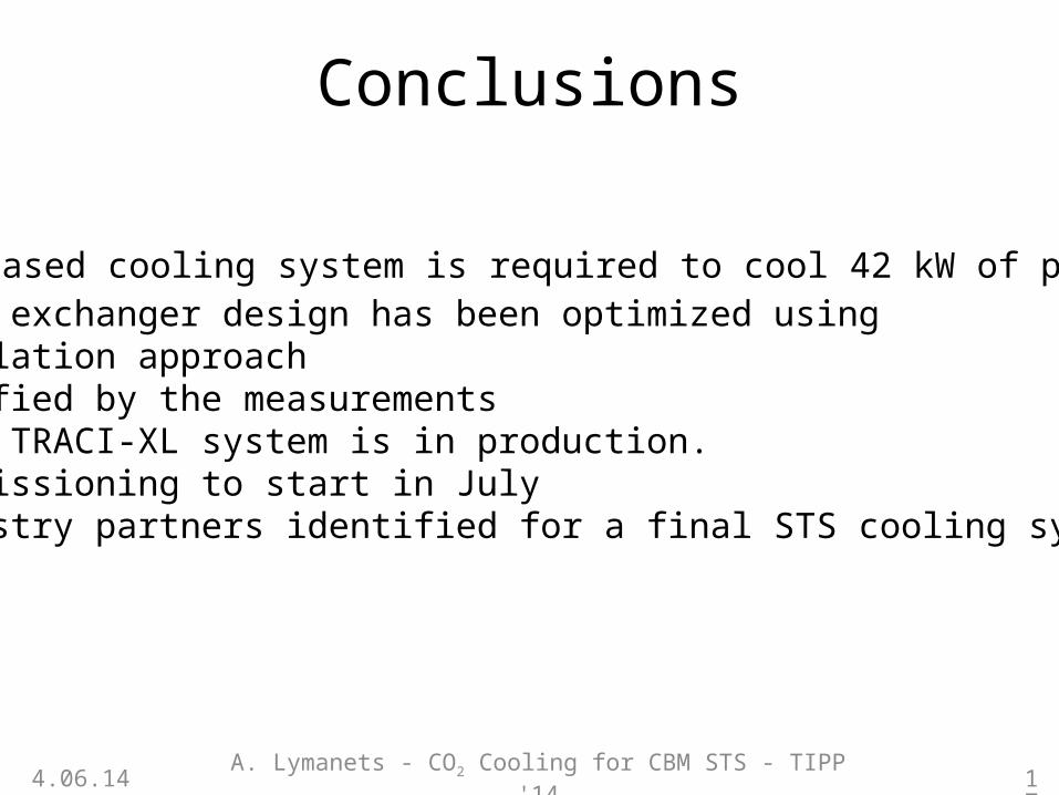
Conclusions
A. Lymanets - CO2 Cooling for CBM STS - TIPP '144.06.14
• CO2 based cooling system is required to cool 42 kW of power.• Heat exchanger design has been optimized using
simulation approach• Verified by the measurements• 1 kW TRACI-XL system is in production.
Commissioning to start in July• Industry partners identified for a final STS cooling system.
17
Related Documents