The Sensoria Reference Modelling Language ? Jos´ e Fiadeiro 1 , Ant´ onia Lopes 2 , Laura Bocchi 1 , and Jo˜ ao Abreu 3 1 Department of Computer Science, University of Leicester, UK {jose,bocchi}@mcs.le.ac.uk 2 Department of Informatics, Faculty of Sciences, University of Lisbon, Portugal [email protected] 3 Altitude Software, Alg´ es, Portugal [email protected] Abstract. This chapter provides an overview of SRML — the Senso- ria Reference Modelling Language. Our focus will be on the language primitives that SRML offers for modelling business services and activi- ties, the methodological approach that SRML supports, and the mathe- matical semantics the underpins the modelling approach, including tech- niques for qualitative and quantitative analysis. 1 Introduction This chapter provides an overview of the modelling language — SRML — that we developed in Sensoria. We present the language primitives that SRML offers for modelling business services and activities, and discuss the methodological ap- proach that SRML supports, which includes the use of the UMC model-checker (developed at CNR-ISTI) for qualitative analysis and of the Markovian process algebra PEPA (developed at the University of Edinburgh) for quantitative anal- ysis of timing properties. Only some elements of the mathematical semantics that we developed for the approach are provided in this chapter; full details can be found in [4,6,29,32,30,33]. Our approach addresses Service-Oriented Computing (SOC) as a new com- putational paradigm in which interactions are no longer based on fixed or pro- grammed exchanges between specific parties — what is known as clientship in object-oriented programming — but on the provisioning of services by external providers that are procured on the fly subject to a negotiation of service level agreements (SLAs). In SOC, the processes of discovery and selection of services are not coded (at design time) as part of the applications that implement busi- ness activities, but performed by the middleware according to functional and non-functional requirements (SLAs). We set ourselves to address the challenge raised on software engineering methodology by the need of declaring such re- quirements as part of the models of service-oriented applications, reflecting the business context in which services and activities are designed. A number of research initiatives have been proposing formal approaches that address different aspects of SOC independently of the specific languages that ? This work has been partially sponsored by the project Sensoria, IST-2005-016004.

Welcome message from author
This document is posted to help you gain knowledge. Please leave a comment to let me know what you think about it! Share it to your friends and learn new things together.
Transcript
The Sensoria Reference Modelling Language?
Jose Fiadeiro1, Antonia Lopes2, Laura Bocchi1, and Joao Abreu3
1Department of Computer Science, University of Leicester, UK{jose,bocchi}@mcs.le.ac.uk
2Department of Informatics, Faculty of Sciences, University of Lisbon, [email protected]
3Altitude Software, Alges, [email protected]
Abstract. This chapter provides an overview of SRML — the Senso-ria Reference Modelling Language. Our focus will be on the languageprimitives that SRML offers for modelling business services and activi-ties, the methodological approach that SRML supports, and the mathe-matical semantics the underpins the modelling approach, including tech-niques for qualitative and quantitative analysis.
1 Introduction
This chapter provides an overview of the modelling language — SRML — thatwe developed in Sensoria. We present the language primitives that SRML offersfor modelling business services and activities, and discuss the methodological ap-proach that SRML supports, which includes the use of the UMC model-checker(developed at CNR-ISTI) for qualitative analysis and of the Markovian processalgebra PEPA (developed at the University of Edinburgh) for quantitative anal-ysis of timing properties. Only some elements of the mathematical semanticsthat we developed for the approach are provided in this chapter; full details canbe found in [4,6,29,32,30,33].
Our approach addresses Service-Oriented Computing (SOC) as a new com-putational paradigm in which interactions are no longer based on fixed or pro-grammed exchanges between specific parties — what is known as clientship inobject-oriented programming — but on the provisioning of services by externalproviders that are procured on the fly subject to a negotiation of service levelagreements (SLAs). In SOC, the processes of discovery and selection of servicesare not coded (at design time) as part of the applications that implement busi-ness activities, but performed by the middleware according to functional andnon-functional requirements (SLAs). We set ourselves to address the challengeraised on software engineering methodology by the need of declaring such re-quirements as part of the models of service-oriented applications, reflecting thebusiness context in which services and activities are designed.
A number of research initiatives have been proposing formal approaches thataddress different aspects of SOC independently of the specific languages that? This work has been partially sponsored by the project Sensoria, IST-2005-016004.
organisations such as OASIS (www.oasis-open.org) and W3C (www.w3.org) aremaking available for Web Services. For example, as presented in Chapter 2-1,several calculi have been developed in Sensoria that address operational foun-dations of SOC (in the sense of how services compute) by providing a mathemat-ical semantics for the mechanisms that support ‘choreography’ or ‘orchestration’— sessions, message/event correlation, compensation, inter alia. Whereas suchcalculi address the need for specialised language primitives for programming inthis new paradigm, they are not abstract enough to understand the engineeringfoundations of SOC, i.e. those aspects (both technical and methodological) thatconcern the way applications can be developed to provide business solutions,independently of the languages in which services are programmed.
This is why, in defining SRML, we used as a source of inspiration the ServiceComponent Architecture (SCA) [2]. SCA makes available a general assemblymodel and binding mechanisms for service components and clients that mayhave been programmed in possibly many different languages, e.g. Java, C++,BPEL, or PHP. However, where SCA supports bottom-up low-level design, ouraim for SRML was, instead, to address top-down high-level design. More specif-ically, our aim was to develop models and mechanisms that support the designof complex services from business requirements, and analysis techniques throughwhich designers can verify or validate properties of composite services that canthen be put together from (heterogeneous) service components using assemblyand binding techniques such as the ones provided by SCA. This shift of emphasisfrom programming to (business) modelling, from component interoperability tobusiness integration, implies that we will be discussing SOC at a level of ab-straction that is different from most other work on Web services (e.g. [10,43]) orGrid computing (e.g. [34]).
Having this in mind, the chapter proceeds as follows. In Section 2, we providean overview of the engineering architecture and processes that we see support-ing SOC in Global Computing. In Section 3, we provide a brief overview of howwe support the transition from business requirements to high-level design mod-els using a (service-oriented) extension of use-case diagrams. In Section 4, weput forward the coordination model on which SRML is based. In Section 5, wepresent the modelling primitives of SRML. In Section 6, we discuss our model ofconfiguration management. In Section 7, we discuss the use of model-checkingtechniques for analysing functional properties of complex services. Finally, in Sec-tion 8, we discuss the use of the Markovian process algebra PEPA for analysingtiming properties. As a running example, we will use a mortgage-brokerage ser-vice that is part of the financial case study developed in Sensoria (cf. Chapter7-4). Although our approach is formal, in the sense that a mathematical se-mantics is available for all the primitives of the language [4,29,30], the paper ismostly mathematics-free with the exception of Sections 4.3, 6, 7.1 and 8.
2 Engineering software for service-overlay computers
The term ‘service’ is being used in a wide variety of contexts, often with differ-ent meanings. In Sensoria, we set ourselves to address the notion of ‘service-overlay computer’, by which we mean the development of highly-distributedloosely-coupled applications over ‘global computers’ (GC) — “computationalinfrastructures available globally and able to provide uniform services with vari-able guarantees for communication, cooperation and mobility, resource usage,security policies and mechanisms” [1].
In this setting, there is a need to rethink the way we engineer software appli-cations, moving from the typical ‘static’ scenario in which components are assem-bled to build a (more or less complex) system that is delivered to a customer, toa more ‘dynamic’ scenario in which (smaller) applications are developed to runon such global computers and respond to business needs by interacting with ser-vices and resources that are globally available. In this latter setting, there is muchmore scope for flexibility in the way business is supported: business processescan be viewed globally as emerging from a varying collection of loosely-coupledapplications that can take advantage of the availability of services procured onthe fly when they are needed.
In this context, the notion of ‘system’ itself, as it applies to software, alsoneeds to be revisited. If we take one of the accepted meanings of system — acombination of related elements organised into a complex whole — we can see whyit is not directly applicable to SOC/GC: services get combined at run time andredefine the way they are organised as they execute; no ‘whole’ is given a prioriand services do not compute within a fixed configuration of a ‘universe’. In asense, we are seeing reflected in software engineering the trend for ‘globalisation’that is now driving the economy.
SOC brings to the front many aspects that have already been discussed aboutcomponent-based development (CBD), for instance in [23]. Given that differentpeople have different perceptions of what SOC and CBD are, we will simplysay that, in this paper, we will take CBD to be associated with what we calledthe static engineering approach. For instance, starting from a universe of (soft-ware) components as structural entities, Broy et al view a service as a way oforchestrating interactions among a subset of components in order to obtain somerequired functionality — “services coordinate the interplay of components to ac-complish specific tasks” [16]. As an example, we can imagine that a bank willhave available a collection of software components that implement core function-alities such as computing interests or charging commissions, which can be usedin different products such as savings or loans.
SOC differs from this view in that there is no such fixed system of com-ponents that services are programmed to draw from but, rather, an evolvinguniverse of software applications that service providers publish so that they canbe discovered by (and bound to) business activities as they execute. For instance,if documents need to be exchanged as part of a loan application, the bank mayrely on an external courier service instead of imposing a fixed one. In this case,a courier service would be discovered for each loan application that is processed,
possibly taking into account the address to which the documents need to be sent,speed of delivery, reliability, and so on. However, the added flexibility providedthrough SOC comes at a price — dynamic interactions impose the overhead ofselecting the co-party at each invocation — which means that the choice be-tween invoking a service and calling a component is a decision that needs to betaken according to given business goals. This is why SRML makes provision forboth SOC and CBD types of interaction (through requires and uses interfacesas discussed in Section 3).
To summarise, the impact that we see SOC to have on software engineeringmethodology stems from the fact that applications are built without knowingwho will provide services that may be required, and that the discovery andselection of such services is performed, on the fly, by dedicated middleware com-ponents. This means that application developers cannot rely on the fact thatsomeone will interact with them to implement the services that may be requiredso as to satisfy their requirements. Therefore, service-oriented ‘clientship’ needsto be based on shared ontologies of data and service provision. Likewise, servicedevelopment is not the same as developing software applications to a costumer’sset of requirements: it is a separate business that, again, has to rely on sharedontologies of data and service provision so that providers can see their servicesdiscovered and selected.
This view is summarised in Fig. 1, where we elaborate beyond the basicService-Oriented Architecture [8] to make explicit the different stakeholders andthe way they interact, which is important for understanding the formal modelthat we are proposing. In this model, we distinguish between ‘business activities’and ‘services’ as software applications that pertain to different stakeholders (see[35] for a wider discussion on the stakeholders of service-oriented systems):
– Activities correspond to applications developed according to requirementsprovided by a business organisation, e.g. the applications that, in a bank,implement the financial products that are made available to the public. Theactivity repository provides a means for a run-time engine to trigger such ap-plications when the corresponding requests are published, say when a clientof the bank requests a loan at a counter or through on-line banking. Activi-ties may be implemented over given components (for instance, a componentfor computing and charging interests) in a traditional CBD way, but theycan also rely on services that will be procured on the fly using SOC (forinstance, an insurance for protecting the customer in case he/she is tem-porarily prevented from re-paying the loan due to illness or job loss). InSRML, activities are modelled through activity modules. As discussed inSection 3, these identify the components that activities need to be bound towhen they are launched and the services (types) that they may require asthey execute. Activity modules also include a specification of the workflowthat orchestrates the interactions among all the parties involved in the activ-ity and a number of SLA constraints used for negotiating service provisionfrom external parties.
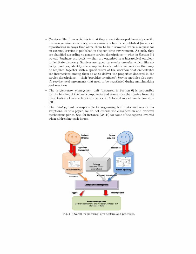
– Services differ from activities in that they are not developed to satisfy specificbusiness requirements of a given organisation but to be published (in servicerepositories) in ways that allow them to be discovered when a request foran external service is published in the run-time environment. As such, theyare classified according to generic service descriptions — what in Section 5.1we call ‘business protocols’ — that are organised in a hierarchical ontologyto facilitate discovery. Services are typed by service modules, which, like ac-tivity modules, identify the components and additional services that maybe required together with a specification of the workflow that orchestratesthe interactions among them so as to deliver the properties declared in theservice descriptions — their ‘provides-interfaces’. Service modules also spec-ify service-level agreements that need to be negotiated during matchmakingand selection.
– The configuration management unit (discussed in Section 6) is responsiblefor the binding of the new components and connectors that derive from theinstantiation of new activities or services. A formal model can be found in[30].
– The ontology unit is responsible for organising both data and service de-scriptions. In this paper, we do not discuss the classification and retrievalmechanisms per se. See, for instance, [38,44] for some of the aspects involvedwhen addressing such issues.
Current configuration (software components and interaction protocols that
interconnect them)
Triggers
Reconfiguration
Discovery and selection Invocation
Business IT teams
Service providers
Publication Application development
Ontology (data and service
descriptions)
Configuration Management
Service repository
tt
Activity repository
Fig. 1. Overall ‘engineering’ architecture and processes.
Notice that the ‘business IT teams’ and the ‘service providers’ can be totallyindependent and unrelated: the former are interested in supporting the businessof their companies or organisations, whereas the latter run a business of theirown. They can also belong to the same organisation, as illustrated in our casestudy. In both cases, they share the ontology component of the architecture sothat they can do business together.
3 From use-case diagrams to SRML modules
Before we introduce the modelling primitives that SRML offers for high-level(business) design, it is important to show how traditional use-case diagramscan be extended so as to support the engineering approach that we described inSection 2. In order to illustrate our approach, we consider the (simplified) case ofa financial services organisation that wants to offer a mortgage-brokerage serviceGetMortgage. This service involves the following steps:
– Proposing the best mortgage deal to the customer that invoked the service;– Taking out the loan if the customer accepts the proposal;– Opening a bank account associated with the loan if the lender does not
provide one;– Getting insurance if required by either the customer or the lender.
In our example, the selection of a lender is restricted to firms that are consid-ered to be reliable. For this reason, we consider an UpdateRegistry activitysupporting the management of a registry of reliable lenders. This activity relieson an external certification authority that may vary according to the identity ofthe lender.
3.1 Use-case diagrams for service-oriented modelling
Traditionally, use-case diagrams are used for providing an overview of usagerequirements for a system that needs to be built. As discussed in Section 2, andreporting to Fig. 1, our aim is to address a novel development process that doesnot aim at the construction of a ‘system’ but, rather, of two kinds of softwareapplications — services and activities — that can be bound to other softwarecomponents either statically (in a component-based way) or dynamically (in aservice-oriented way). The methodological implications of this view are twofold.On the one hand, services and activities have the particularity that each has asingle usage requirement. Hence, they can be perceived as use cases. On the otherhand, from a business point of view, the services and activities to be developedby an organisation constitute logical units.
In our example, UpdateRegistry should be treated as an activity in thesense that it is driven by the requirements of the financial services organisationitself — it will be stored in an activity repository and will be invoked by internalapplications (e.g., a web interface). On the other hand, GetMortgage is meant
to be placed in a service repository for being discovered and bound to activitiesrunning ‘globally’, i.e. not necessarily in the financial services organisation.
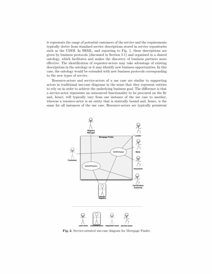
Both UpdateRegistry and GetMortgage can be seen to operate as partof a same business unit and, hence, it makes sense to group them in the same use-case diagram — use-case diagrams are useful for structuring usage requirementsof units of business logic. In order to reflect the methodological implications ofour approach, we propose a number of extensions to the standard notation of usecases. Fig. 2 uses the mortgage example to illustrate our proposal: the diagramrepresents a business logical unit with the two use cases identified before. Therectangle around the use cases, which in traditional use-case diagrams indicatesthe boundary of the system at hand, is used to indicate the scope of the busi-ness unit. Anything within the box represents functionality that is in scope andanything outside the box is considered not to be in scope.
For the UpdateRegistry activity, the primary actor is Registry Manager;its goal is to control the way a registry of trusted lenders is updated. The registryitself is regarded as a supporting actor. The Certification Authority on whichUpdateRegistry relies is also considered a supporting actor in the use casebecause it is an external service that needs to be discovered based on the natureof the lender being considered.
In the GetMortgage service, the primary actor is a Customer that wantsto obtain a mortgage. The use case has four supporting actors: Lender, Bank,Insurance and Registry. The Lender represents the organisation (e.g., a bank orbuilding society) that lends the money to the customer. Because only reliablefirms can be considered for the selection of the lender, the use case involvescommunication with Registry. When the lender does not provide a bank account,the use case involves an external Bank for opening a new account. Similarly, theuse case involves interaction with an Insurance provider for situations where thelender requires insurance or the customer decides to get one.
As in traditional use cases, we view an actor as any entity that is externalto the business unit and interacts with at least one of its elements in order toperform a task. As motivated above, we can distinguish between different kindsof actors, which led us to customise the traditional icons as depicted in Fig. 2.These allow us to discriminate between user/requester and resource/service ac-tors. User-actors and requester-actors are similar to primary actors in traditionaluse-case diagrams in the sense that they represent entities that initiate the usecase and whose goals are fulfilled through the successful completion of the usecase. The difference between them is that a user-actor is a role played by anentity that interacts with the activity, while a requester-actor is a role played byone or more software components operating as part of the activity that triggersthe discovery of the service.
For instance, the user-actor Registry Manager represents an interface for anemployee of the business organisation that is running Mortgage Finder whereasthe requester-actor Customer represents an interface for a service requester thatcan come from any external organisation. A requester-actor can be regarded asan interface to an abstract user of the functionality that is exposed as a service;
it represents the range of potential customers of the service and the requirementstypically derive from standard service descriptions stored in service repositoriessuch as the UDDI. In SRML, and reporting to Fig. 1, these descriptions aregiven by business protocols (discussed in Section 5.1) and organised in a sharedontology, which facilitates and makes the discovery of business partners moreeffective. The identification of requester-actors may take advantage of existingdescriptions in the ontology or it may identify new business opportunities. In thiscase, the ontology would be extended with new business protocols correspondingto the new types of service.
Resource-actors and service-actors of a use case are similar to supportingactors in traditional use-case diagrams in the sense that they represent entitiesto rely on in order to achieve the underlying business goal. The difference is thata service-actor represents an outsourced functionality to be procured on the flyand, hence, will typically vary from one instance of the use case to another,whereas a resource-actor is an entity that is statically bound and, hence, is thesame for all instances of the use case. Resource-actors are typically persistent
Mortgage Finder
Customer
Lender
Bank
InsuranceUpdateRegistry
CertificationAuthority
Registry
GetMortgage
resource-actoruser-actor requester-actor
Registry Manager
service-actor
Fig. 2. Service-oriented use-case diagram for Mortgage Finder.
sources/repositories of information. In general, they are components that arealready available to be shared within a business organisation.
The user- and resource-actors, which we represent at the top and bottom ofour specialised use-case diagrams, respectively, correspond in fact to the actorsthat are presented on the left and right-hand side in traditional use-case dia-grams, respectively. In contrast, the horizontal dimension of the new diagrams,comprising requester-and service-actors, captures the types of interactions thatare specific to SOC.
We assume that every use case corresponds to a service-oriented artefactand that the association between a primary actor and a use case represents aninstantiation/invocation. For this reason, in this context, we constrain every usecase to be associated with only one primary actor (either a requester or a user).
3.2 Deriving the structure of SRML modules
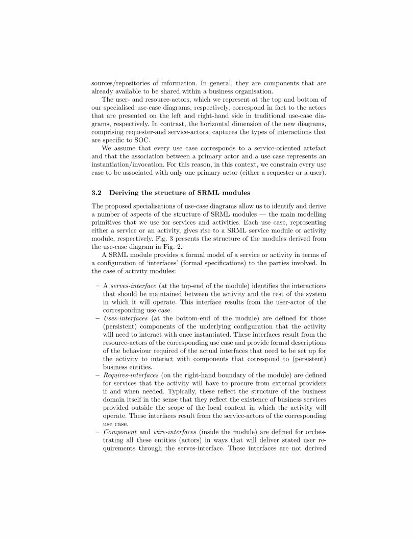
The proposed specialisations of use-case diagrams allow us to identify and derivea number of aspects of the structure of SRML modules — the main modellingprimitives that we use for services and activities. Each use case, representingeither a service or an activity, gives rise to a SRML service module or activitymodule, respectively. Fig. 3 presents the structure of the modules derived fromthe use-case diagram in Fig. 2.
A SRML module provides a formal model of a service or activity in terms ofa configuration of ‘interfaces’ (formal specifications) to the parties involved. Inthe case of activity modules:
– A serves-interface (at the top-end of the module) identifies the interactionsthat should be maintained between the activity and the rest of the systemin which it will operate. This interface results from the user-actor of thecorresponding use case.
– Uses-interfaces (at the bottom-end of the module) are defined for those(persistent) components of the underlying configuration that the activitywill need to interact with once instantiated. These interfaces result from theresource-actors of the corresponding use case and provide formal descriptionsof the behaviour required of the actual interfaces that need to be set up forthe activity to interact with components that correspond to (persistent)business entities.
– Requires-interfaces (on the right-hand boundary of the module) are definedfor services that the activity will have to procure from external providersif and when needed. Typically, these reflect the structure of the businessdomain itself in the sense that they reflect the existence of business servicesprovided outside the scope of the local context in which the activity willoperate. These interfaces result from the service-actors of the correspondinguse case.
– Component and wire-interfaces (inside the module) are defined for orches-trating all these entities (actors) in ways that will deliver stated user re-quirements through the serves-interface. These interfaces are not derived
from the use-case diagram but from the description of the correspondingbusiness requirements, i.e. they result from a design step. Typically, a de-signer will choose pre-defined patterns of orchestration that reflect businesscomponents that will be created in support of the activity or chosen from aportfolio of components already available for reuse within the business organ-isation. The choice of the internal architecture of the module (componentsand wires) should also reflect the nature of the business communication anddistribution network over which the activity will run.
In the case of a service module, a similar diagrammatic notation is usedexcept that a provides-interface is used instead of a serves-interface:
– The provides-interface should be chosen from the hierarchy of standard busi-ness protocols because the purpose here is to make the service available tothe wider market, not to a specific client. It derives from the requester-actorof the corresponding use case.
– Some of the component interfaces will correspond to standard componentsthat are part of the provider’s portfolio. For instance, these may be application-
GETMORTGAGE
SLA_GM
RE:Registry
MA:MortgageAgent
LE:Lender
intLE
BA:Bank
intBA
IN:Insurance
intIN
CM CR: Customer
ME
ML
MB
MI
intMA
UPDATEREGISTRY
SLA_UR
RE:Registry
MC:ManagementCoordinator
CA:Certification
Autority
intCA
MR
MA
RM:RegistryManager
RMintMC
Fig. 3. The SRML modules for the activity UpdateRegistry and the service Get-Mortgage.
domain dependent components that correspond to typical entities of thebusiness domain in which the service provider specialises.
– Uses-interfaces should be used for those components that the service providerhas for insuring persistence of certain effects of the services that it offers.
In addition, both activity and service modules include:
– An internal configuration policy (indicated by the symbol ), which iden-tifies the triggers of the external service discovery process as well as theinitialisation and termination conditions of the components that instantiatethe component-interfaces.
– An external configuration policy (indicated by the symbol ), whichconsists of the variables and constraints that determine the quality profileof the activity to which the discovered services need to adhere.
The language primitives that are used in SRML for defining all these inter-faces as well as the configuration policies are detailed in Section 5. A summaryof the graphical notation can be found in Appendix A at the end of the paper.
4 The coordination model
The interfaces of a SRML module identified through a use-case diagram reflectbusiness dependencies of services or activities, not the interfaces that softwarecomponents offer to be interconnected: modules are not models of componentsbut of business processes. In this section, we detail the coordination model thatSRML adopts for component interconnection, i.e. we address the nature of theinterfaces that components offer and the way wires interconnect them. We alsooutline a formalisation of this model, full details of which are available from[4,29].
4.1 Conversational interactions
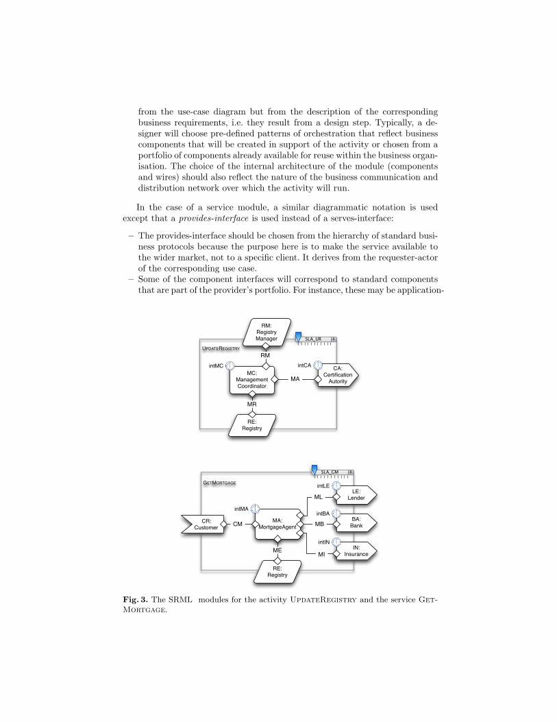
Typically, in CBD, one organises component interfaces (what they offer to andexpect from the rest of the system) in ports, which include the protocols thatregulate message exchange at those ports. In SRML, we have fixed the nature ofthe interactions and protocols followed by components and wires. We distinguishthe following types of interactions:
r&s The interaction is initiated by the co-party, which expects a reply.The co-party does not block while waiting for the reply.
s&r The interaction is initiated by the party and expects a reply from itsco-party. While waiting for the reply, the party does not block.
rcv The co-party initiates the interaction and does not expect a reply.snd The party initiates the interaction and does not expect a reply.ask The party synchronises with the co-party to obtain data.rpl The party synchronises with the co-party to transmit data.tll The party requests the co-party to perform an operation and blocks.prf The party performs an operation and frees the co-party that requested it.
Interactions involve two parties and are described from the point of view ofthe party in which they are declared, i.e. ‘receive’ means invocations receivedby the party and sent by the co-party, and ‘send’ means invocations made bythe party. Interactions can be synchronous, implying that the party waits forthe co-party to reply or complete, or asynchronous, in which case the party doesnot block. Typically, synchronous (blocking) interactions (i.e., ask, rpl, tll andprf) occur with persistent components, reflecting interconnections based on theexchange of products (clientship as in OO). The interactions among the compo-nents responsible for the orchestration and those involving external services aretypically asynchronous (non-blocking, i.e., r&s, s&r, snd and rcv) so that theparties can engage in multiple, concurrent conversations. Interactions of typer&s and s&r are conversational (what we call 2-way), i.e. they involve a numberof events exchanged between the two parties:
interaction The event of initiating interaction.interaction� The reply-event of interaction.interactionX The commit-event of interaction.interaction8 The cancel-event of interaction.interaction> The revoke-event of interaction.
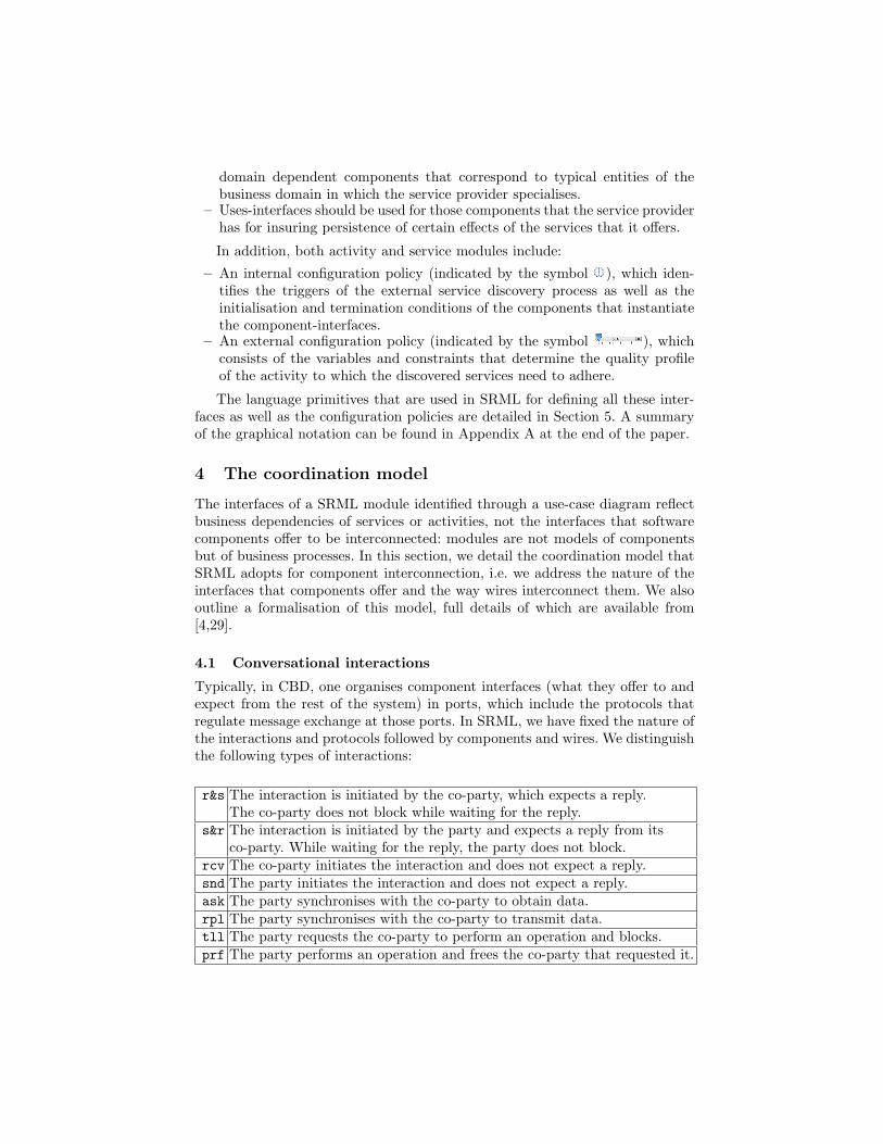
The initiation-event is the only event that can be associated with 1-way asyn-chronous interaction types (snd,rcv). The reply-event is sent by the co-party,offering a deal or declining to offer one; in the first case, the party that initi-ated the conversation may either commit to the deal or cancel the interaction;after committing, the party can still revoke the deal, triggering a compensa-tion mechanism. See Fig. 4 for some of the possible scenarios (explained furtherbelow).
All interactions can have parameters for transmitting data when they areinitiated — declared as . Conversational interactions can also have parametersfor carrying a reply — declared as � — or for carrying data if there is a commit,a cancel or a revoke — declared as X, 8 and >, respectively. In particular, everyreply-event interaction� has two distinguished parameters:
– Reply is a Boolean parameter that indicates whether the reply is positive,meaning that the co-party is ready to proceed. The value of interaction.Reply
a a a
a a a
a a
a a.useBy
S R S R S R
Fig. 4. The protocol of 2-way interactions when the reply is positive.
is False if, for some reason related with the business logic, the requestinteraction cannot be fulfilled.
– UseBy is a parameter that, in the case of a positive reply, indicates the dead-line for receiving the commit and cancel events. The value of this parameteris an expiration time (including the value +∞) obtained by adding the valueof the configuration variable (non-functional attribute) interaction to theinstant at which interaction� is sent. As discussed in Section 5.2, configu-ration variables can be subject to negotiation during the discovery/selectionprocess.
Interactions can be seen as ports in the traditional CBD sense, the associatedevents representing the interface of the components. The sequence diagramsin Fig. 4 illustrate the protocol that is associated with every interaction forwhich the reply is positive. In the case on the left, the initiator commits to thedeal; a revoke may occur later on, compensating the effects of the commit-eventinteractionX(this can however be constrained by the business logic, for instance,by defining a deadline for compensation). In the middle, there is a cancellation;in this situation, a revoke is not available. In the case on the right, the expirationtime occurs without a commit or cancel having occurred; this implies that nofurther events for that interaction will occur. In Section 5, we give examples ofthe intended usage of these primitives.
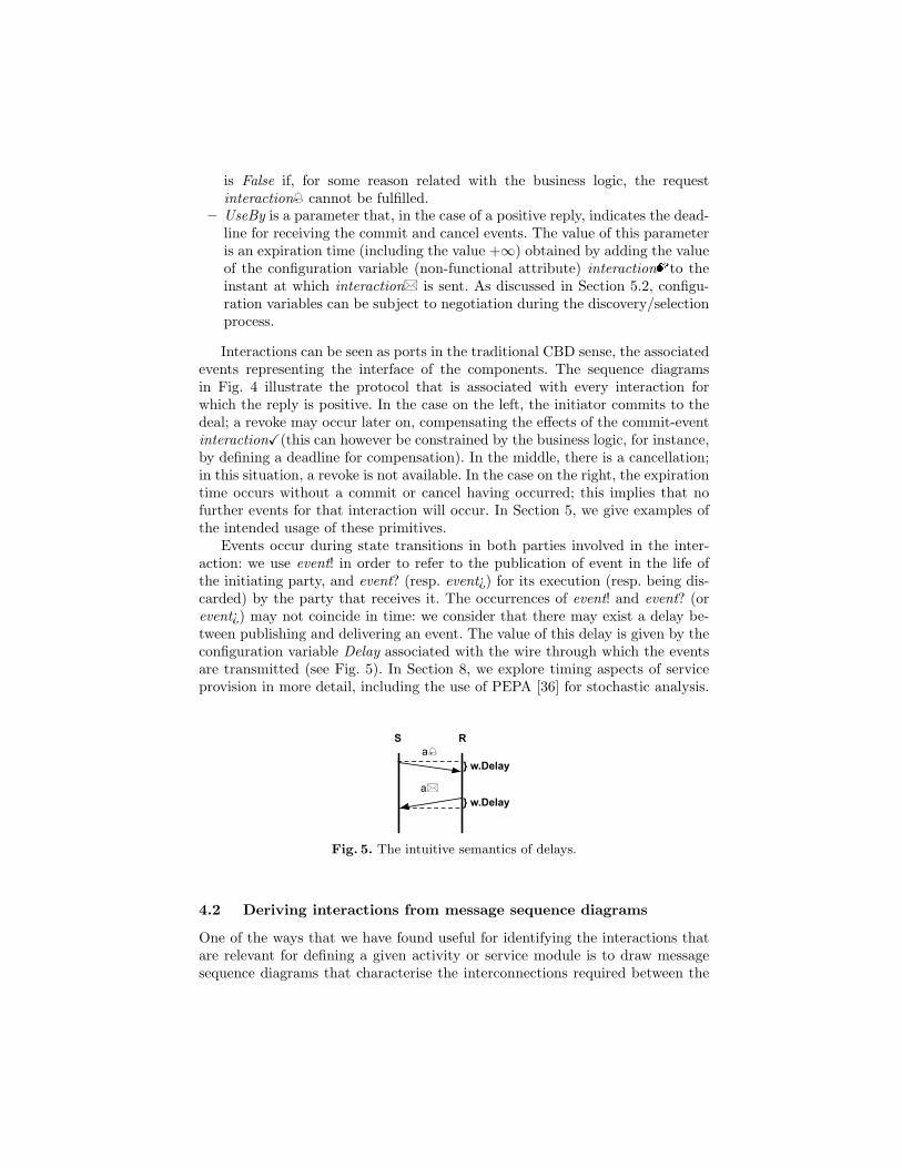
Events occur during state transitions in both parties involved in the inter-action: we use event! in order to refer to the publication of event in the life ofthe initiating party, and event? (resp. event¿) for its execution (resp. being dis-carded) by the party that receives it. The occurrences of event! and event? (orevent¿) may not coincide in time: we consider that there may exist a delay be-tween publishing and delivering an event. The value of this delay is given by theconfiguration variable Delay associated with the wire through which the eventsare transmitted (see Fig. 5). In Section 8, we explore timing aspects of serviceprovision in more detail, including the use of PEPA [36] for stochastic analysis.
a
a
S R
} w.Delay
} w.Delay
Fig. 5. The intuitive semantics of delays.
4.2 Deriving interactions from message sequence diagrams
One of the ways that we have found useful for identifying the interactions thatare relevant for defining a given activity or service module is to draw messagesequence diagrams that characterise the interconnections required between the
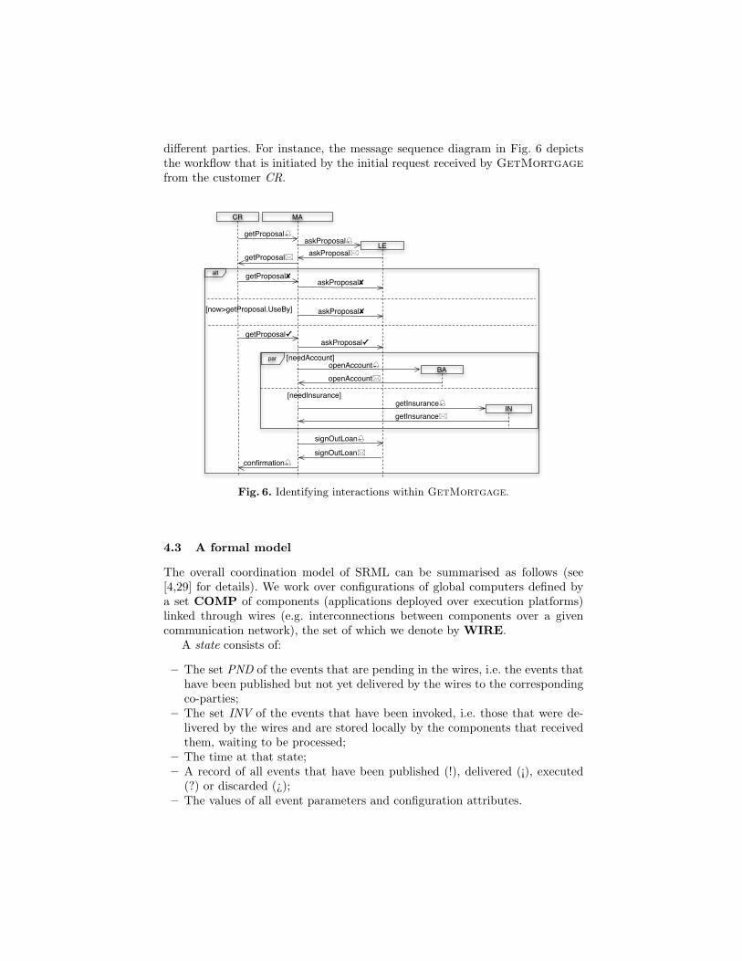
different parties. For instance, the message sequence diagram in Fig. 6 depictsthe workflow that is initiated by the initial request received by GetMortgagefrom the customer CR.
alt
par
MACR
BA
IN
getProposalaskProposal
askProposalgetProposal
getProposal✘
getProposal✓
askProposal✘
askProposal✓
openAccountopenAccount
getInsurance
signOutLoan
signOutLoanconfirmation
getInsurance
[now>getProposal.UseBy] askProposal✘
[needAccount]
[needInsurance]
LE
Fig. 6. Identifying interactions within GetMortgage.
4.3 A formal model
The overall coordination model of SRML can be summarised as follows (see[4,29] for details). We work over configurations of global computers defined bya set COMP of components (applications deployed over execution platforms)linked through wires (e.g. interconnections between components over a givencommunication network), the set of which we denote by WIRE.
A state consists of:
– The set PND of the events that are pending in the wires, i.e. the events thathave been published but not yet delivered by the wires to the correspondingco-parties;
– The set INV of the events that have been invoked, i.e. those that were de-livered by the wires and are stored locally by the components that receivedthem, waiting to be processed;
– The time at that state;– A record of all events that have been published (!), delivered (¡), executed
(?) or discarded (¿);– The values of all event parameters and configuration attributes.
In this model, state transitions are characterised by what we call a compu-tation step, consisting of:
– An ordered pair of states SRC (source) and TRG (target);– A subset DLV of PNDSRC consisting of the events that are pending in the
source state and selected for delivery during that step;– A set PRC that selects from INV SRC one event for every component that
has events waiting to be processed;– A subset EXC of PRC consisting of the events that are actually executed
(the others are discarded);– A set PUB of the events that are published during that step together with
a function that assigns a value to the parameters of each such event.
These elements are subject to the following constraints:
– The set INV TRG of the events in the target state that have been invokedconsists of the events in DLV (i.e. those that are delivered during the step)together with those already in INV SRC that have not been selected by PRCto be processed;
– The set PNDTRG of the events that are pending at the target state consistsof the events in PUB (i.e. those that are published during the step) togetherwith the events in PNDSRC that have not been selected by DLV to bedelivered.
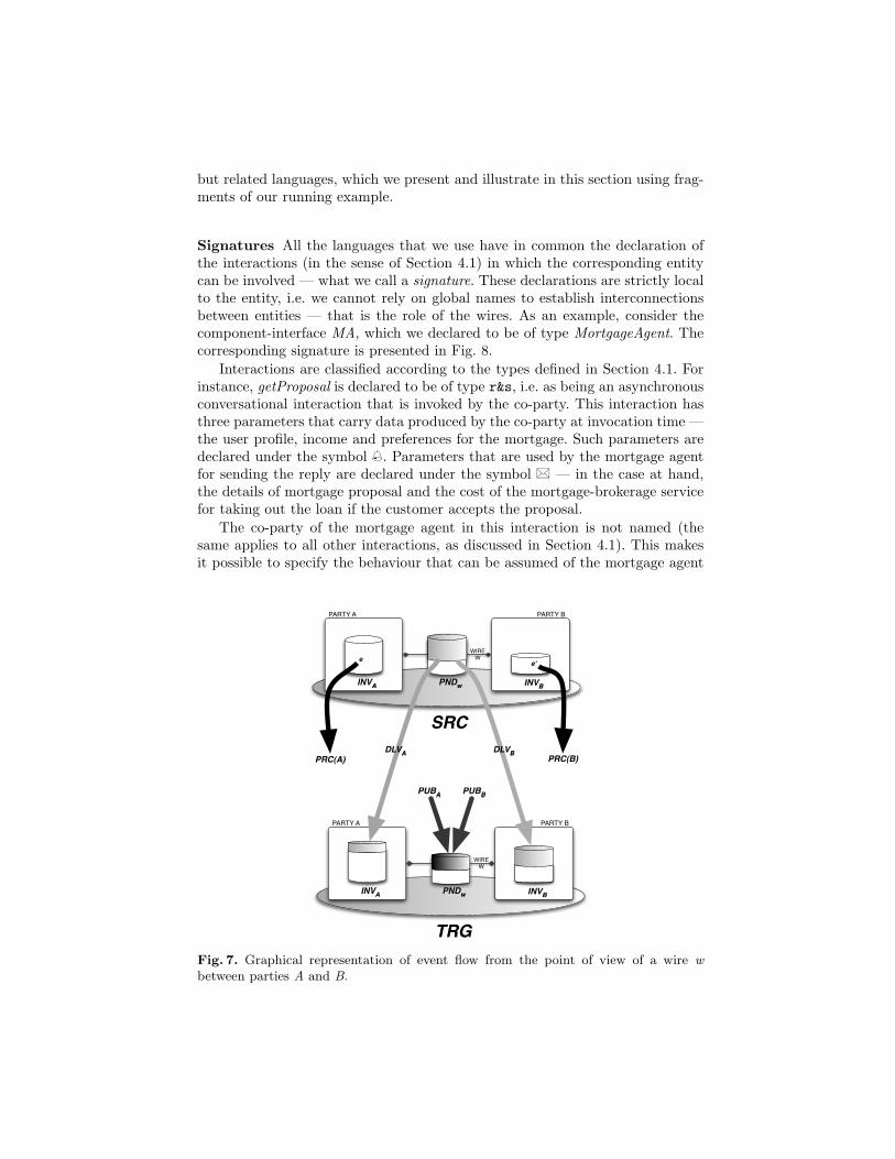
That is, the set of events that are pending in wires is updated during eachcomputation step by removing the events that the wire delivers during that step— DLV — and adding the events that each component publishes — PUB. Weassume that all the events that are selected by DLV are actually delivered tothe receiving component, i.e. each wire is reliable — see [4,29] for a model thatconsiders unreliable wires.
At each step, components may select one of the events waiting to be pro-cessed; this is captured by the function PRC. The fact each component can onlyprocess one event at a time is justified by the assumption that the internal stateof the components is not necessarily distributed and therefore no concurrentchanges can be made to their states.
The set of events that are waiting to be processed by every component isupdated in each step by removing the event that is processed and adding theevents that are actually delivered to that component. Fig. 7 is a graphical repre-sentation of the flow of events that takes place during a computation step fromthe point of view of components A and B connected by a wire w.
5 The modelling primitives of SRML
5.1 Behaviour specification languages
The entities involved in service and activity modules — component interfaces,requires-interfaces, provides-interfaces, uses-interfaces, serves-interfaces and wire-interfaces — can be defined in SRML independently of one another as design-time reusable resources. For that purpose, we have defined a number of different
but related languages, which we present and illustrate in this section using frag-ments of our running example.
Signatures All the languages that we use have in common the declaration ofthe interactions (in the sense of Section 4.1) in which the corresponding entitycan be involved — what we call a signature. These declarations are strictly localto the entity, i.e. we cannot rely on global names to establish interconnectionsbetween entities — that is the role of the wires. As an example, consider thecomponent-interface MA, which we declared to be of type MortgageAgent. Thecorresponding signature is presented in Fig. 8.
Interactions are classified according to the types defined in Section 4.1. Forinstance, getProposal is declared to be of type r&s, i.e. as being an asynchronousconversational interaction that is invoked by the co-party. This interaction hasthree parameters that carry data produced by the co-party at invocation time —the user profile, income and preferences for the mortgage. Such parameters aredeclared under the symbol . Parameters that are used by the mortgage agentfor sending the reply are declared under the symbol � — in the case at hand,the details of mortgage proposal and the cost of the mortgage-brokerage servicefor taking out the loan if the customer accepts the proposal.
The co-party of the mortgage agent in this interaction is not named (thesame applies to all other interactions, as discussed in Section 4.1). This makesit possible to specify the behaviour that can be assumed of the mortgage agent
PARTY A PARTY B
INVA INVBPNDw
WIREWe e'
TRG
PARTY A PARTY B
INVA INVBPNDw
WIREW
SRC
PUBA PUBB
PRC(B)DLVBDLVA
PRC(A)
Fig. 7. Graphical representation of event flow from the point of view of a wire wbetween parties A and B.
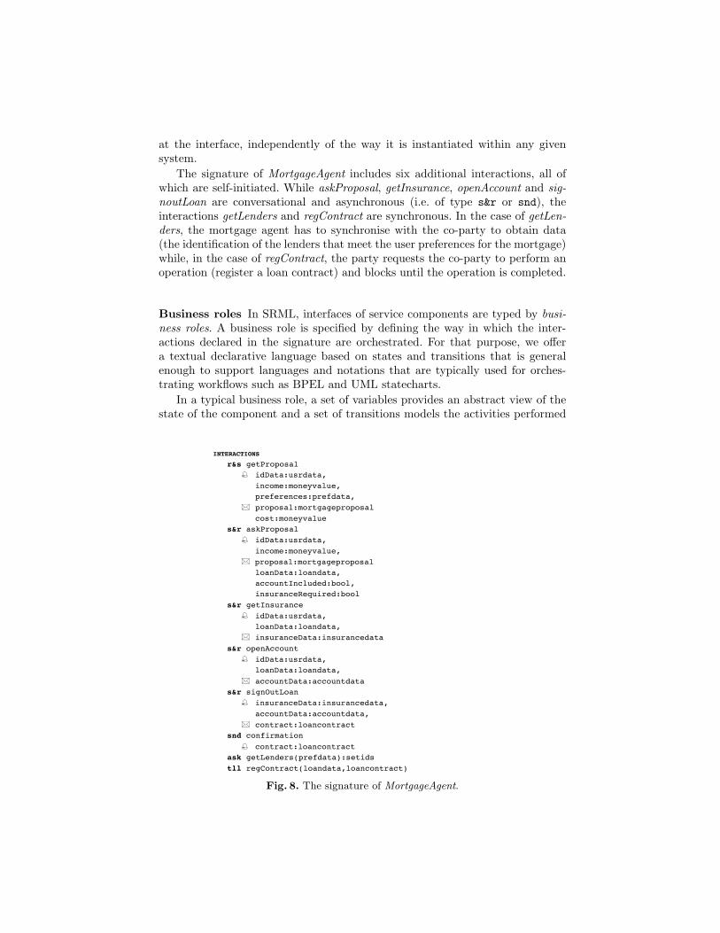
at the interface, independently of the way it is instantiated within any givensystem.
The signature of MortgageAgent includes six additional interactions, all ofwhich are self-initiated. While askProposal, getInsurance, openAccount and sig-noutLoan are conversational and asynchronous (i.e. of type s&r or snd), theinteractions getLenders and regContract are synchronous. In the case of getLen-ders, the mortgage agent has to synchronise with the co-party to obtain data(the identification of the lenders that meet the user preferences for the mortgage)while, in the case of regContract, the party requests the co-party to perform anoperation (register a loan contract) and blocks until the operation is completed.
Business roles In SRML, interfaces of service components are typed by busi-ness roles. A business role is specified by defining the way in which the inter-actions declared in the signature are orchestrated. For that purpose, we offera textual declarative language based on states and transitions that is generalenough to support languages and notations that are typically used for orches-trating workflows such as BPEL and UML statecharts.
In a typical business role, a set of variables provides an abstract view of thestate of the component and a set of transitions models the activities performed
– 4 –
SPECIFICATIONS
LAYER PROTOCOL Registry is
INTERACTIONS rpl getLenders(prefdata):setids prf registerContract(loandata,loancontract) BEHAVIOUR
BUSINESS ROLE MortgageAgent is
INTERACTIONS r&s getProposal idData:usrdata, income:moneyvalue, preferences:prefdata, proposal:mortgageproposal cost:moneyvalue
s&r askProposal idData:usrdata,
income:moneyvalue, proposal:mortgageproposal loanData:loandata, accountIncluded:bool, insuranceRequired:bool s&r getInsurance idData:usrdata, loanData:loandata, insuranceData:insurancedata s&r openAccount idData:usrdata, loanData:loandata, accountData:accountdata s&r signOutLoan insuranceData:insurancedata, accountData:accountdata, contract:loancontract snd confirmation
contract:loancontract ask getLenders(prefdata):setids tll regContract(loandata,loancontract)
SLA VARIABLES CHARGE:[0..100]
ORCHESTRATION
local s:[INITIAL, WAIT_PROPOSAL, WAIT_DECISION, PROPOSAL_ACCEPTED, SIGNING, FINAL], lenders:setids, needAccount, needInsurance:bool, insuranceData:insurancedata, accountData:accountdata
Fig. 8. The signature of MortgageAgent.
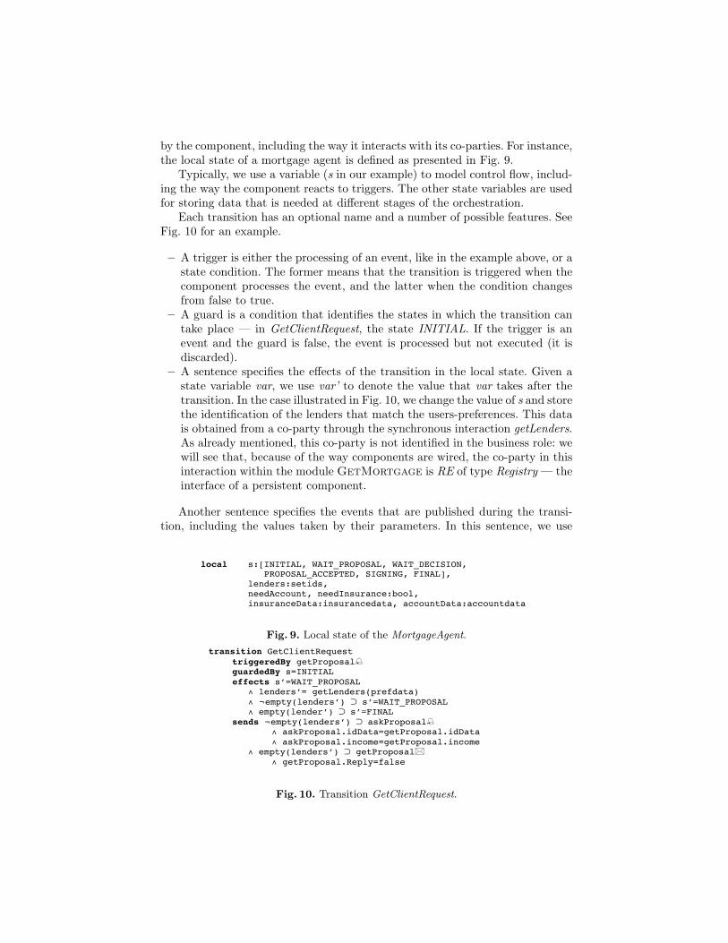
by the component, including the way it interacts with its co-parties. For instance,the local state of a mortgage agent is defined as presented in Fig. 9.
Typically, we use a variable (s in our example) to model control flow, includ-ing the way the component reacts to triggers. The other state variables are usedfor storing data that is needed at different stages of the orchestration.
Each transition has an optional name and a number of possible features. SeeFig. 10 for an example.
– A trigger is either the processing of an event, like in the example above, or astate condition. The former means that the transition is triggered when thecomponent processes the event, and the latter when the condition changesfrom false to true.
– A guard is a condition that identifies the states in which the transition cantake place — in GetClientRequest, the state INITIAL. If the trigger is anevent and the guard is false, the event is processed but not executed (it isdiscarded).
– A sentence specifies the effects of the transition in the local state. Given astate variable var, we use var’ to denote the value that var takes after thetransition. In the case illustrated in Fig. 10, we change the value of s and storethe identification of the lenders that match the users-preferences. This datais obtained from a co-party through the synchronous interaction getLenders.As already mentioned, this co-party is not identified in the business role: wewill see that, because of the way components are wired, the co-party in thisinteraction within the module GetMortgage is RE of type Registry — theinterface of a persistent component.
Another sentence specifies the events that are published during the transi-tion, including the values taken by their parameters. In this sentence, we use
– 4 –
SPECIFICATIONS
LAYER PROTOCOL Registry is
INTERACTIONS rpl getLenders(prefdata):setids prf registerContract(loandata,loancontract) BEHAVIOUR
BUSINESS ROLE MortgageAgent is
INTERACTIONS r&s getProposal idData:usrdata, income:moneyvalue, preferences:prefdata, proposal:mortgageproposal cost:moneyvalue
s&r askProposal idData:usrdata,
income:moneyvalue, proposal:mortgageproposal loanData:loandata, accountIncluded:bool, insuranceRequired:bool s&r getInsurance idData:usrdata, loanData:loandata, insuranceData:insurancedata s&r openAccount idData:usrdata, loanData:loandata, accountData:accountdata s&r signOutLoan insuranceData:insurancedata, accountData:accountdata, contract:loancontract snd confirmation
contract:loancontract ask getLenders(prefdata):setids tll regContract(loandata,loancontract)
SLA VARIABLES CHARGE:[0..100]
ORCHESTRATION
local s:[INITIAL, WAIT_PROPOSAL, WAIT_DECISION, PROPOSAL_ACCEPTED, SIGNING, FINAL], lenders:setids, needAccount, needInsurance:bool, insuranceData:insurancedata, accountData:accountdata
Fig. 9. Local state of the MortgageAgent.
– 5 –
transition GetClientRequest triggeredBy getProposal guardedBy s=INITIAL effects s’=WAIT_PROPOSAL ∧ lenders’= getLenders(prefdata) ∧ ¬empty(lenders’) ⊃ s’=WAIT_PROPOSAL ∧ empty(lender’) ⊃ s’=FINAL sends ¬empty(lenders’) ⊃ askProposal ∧ askProposal.idData=getProposal.idData ∧ askProposal.income=getProposal.income ∧ empty(lenders’) ⊃ getProposal ∧ getProposal.Reply=false
transition GetLenderProposal triggeredBy askProposal guardedBy s=WAIT_PROPOSAL effects needAccount’=askProposal.accountIncluded ∧ needInsurance’=askProposal.insuranceRequired ∧ askProposal.Reply ⊃ s’=WAIT_DECISION ∧ ¬askProposal.Reply ⊃ s’=FINAL sends getProposal ∧ getProposal.Reply=askProposal.Reply ∧ getProposal.proposal=askProposal.proposal ∧ getProposal.cost=(CHARGE/100+1)*750
transition TimeoutProposal triggeredBy now>getProposal.UseBy guardedBy s=WAIT_DECISION effects s’=FINAL sends askProposal
transition ProposalNotAccepted triggeredBy getProposal guardedBy s=WAIT_DECISION ∧ now<askProposal.UseBy effects s’=FINAL sends askProposal transition ProposalAccepted triggeredBy getProposal guardedBy s=WAIT_DECISION ∧ now<deadline effects needAccount ∨ needInsurance ⊃ s’=PROPOSAL_ACCEPTED ∧ ¬needAccount ∧ ¬needInsurance ⊃ s’=SIGNING sends askProposal ∧ needAccount ⊃ openAccount ∧ openAccount.idData=getProposal.idData ∧ openAccount.loanData=getProposal.loanData ∧ needInsurance ⊃ getInsurance ∧ getInsurance.idData=getProposal.idData ∧ getInsurance.loanData=getProposal.loanData ∧ ¬needAccount ∧ ¬needInsurance ⊃ signOutLoan ∧ signOutLoan.insuranceData=insuranceData ∧ signOutLoan.accountData=accountData
transition GetAccount triggeredBy openAccount guardedBy s=PROPOSAL_ACCEPTED effects needAccount’=false ∧ ¬needInsurance ⊃ s’=SIGNINING ∧ accountData=openAccount.accountData sends ¬needInsurance ⊃ signOutLoan ∧ signOutLoan.insuranceData=insuranceData
Fig. 10. Transition GetClientRequest.
variables and primed variables as in the ‘effects’-section. In the example, if thereis at least one lender that matches the user-preferences, the interaction askPro-posal is initiated in order to get a mortgage proposal from a lender. Once again,the corresponding co-party is not named: we will see that, within the moduleGetMortgage, this is an external service provided by a bank or building soci-ety that needs to be discovered and bound to the mortgage agent. If no lendersare found that match the user-preferences, a negative reply to getProposal ispublished.
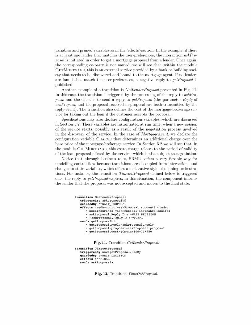
Another example of a transition is GetLenderProposal presented in Fig. 11.In this case, the transition is triggered by the processing of the reply to askPro-posal and the effect is to send a reply to getProposal (the parameter Reply ofaskProposal and the proposal received in proposal are both transmitted by thereply-event). The transition also defines the cost of the mortgage-brokerage ser-vice for taking out the loan if the customer accepts the proposal.
Specifications may also declare configuration variables, which are discussedin Section 5.2. These variables are instantiated at run time, when a new sessionof the service starts, possibly as a result of the negotiation process involvedin the discovery of the service. In the case of MortgageAgent, we declare theconfiguration variable Charge that determines an additional charge over thebase price of the mortgage-brokerage service. In Section 5.2 we will see that, inthe module GetMortgage, this extra-charge relates to the period of validityof the loan proposal offered by the service, which is also subject to negotiation.
Notice that, through business roles, SRML offers a very flexible way formodelling control flow because transitions are decoupled from interactions andchanges to state variables, which offers a declarative style of defining orchestra-tions. For instance, the transition TimeoutProposal defined below is triggeredonce the reply to getProposal expires; in this situation, the component informsthe lender that the proposal was not accepted and moves to the final state.
– 5 –
transition GetClientRequest triggeredBy getProposal guardedBy s=INITIAL effects s’=WAIT_PROPOSAL ∧ lenders’= getLenders(prefdata) ∧ ¬empty(lenders’) ⊃ s’=WAIT_PROPOSAL ∧ empty(lender’) ⊃ s’=FINAL sends ¬empty(lenders’) ⊃ askProposal ∧ askProposal.idData=getProposal.idData ∧ askProposal.income=getProposal.income ∧ empty(lenders’) ⊃ getProposal ∧ getProposal.Reply=false
transition GetLenderProposal triggeredBy askProposal guardedBy s=WAIT_PROPOSAL effects needAccount’=askProposal.accountIncluded ∧ needInsurance’=askProposal.insuranceRequired ∧ askProposal.Reply ⊃ s’=WAIT_DECISION ∧ ¬askProposal.Reply ⊃ s’=FINAL sends getProposal ∧ getProposal.Reply=askProposal.Reply ∧ getProposal.proposal=askProposal.proposal ∧ getProposal.cost=(CHARGE/100+1)*750
transition TimeoutProposal triggeredBy now>getProposal.UseBy guardedBy s=WAIT_DECISION effects s’=FINAL sends askProposal
transition ProposalNotAccepted triggeredBy getProposal guardedBy s=WAIT_DECISION ∧ now<askProposal.UseBy effects s’=FINAL sends askProposal transition ProposalAccepted triggeredBy getProposal guardedBy s=WAIT_DECISION ∧ now<deadline effects needAccount ∨ needInsurance ⊃ s’=PROPOSAL_ACCEPTED ∧ ¬needAccount ∧ ¬needInsurance ⊃ s’=SIGNING sends askProposal ∧ needAccount ⊃ openAccount ∧ openAccount.idData=getProposal.idData ∧ openAccount.loanData=getProposal.loanData ∧ needInsurance ⊃ getInsurance ∧ getInsurance.idData=getProposal.idData ∧ getInsurance.loanData=getProposal.loanData ∧ ¬needAccount ∧ ¬needInsurance ⊃ signOutLoan ∧ signOutLoan.insuranceData=insuranceData ∧ signOutLoan.accountData=accountData
transition GetAccount triggeredBy openAccount guardedBy s=PROPOSAL_ACCEPTED effects needAccount’=false ∧ ¬needInsurance ⊃ s’=SIGNINING ∧ accountData=openAccount.accountData sends ¬needInsurance ⊃ signOutLoan ∧ signOutLoan.insuranceData=insuranceData
Fig. 11. Transition GetLenderProposal.
– 5 –
transition GetClientRequest triggeredBy getProposal guardedBy s=INITIAL effects s’=WAIT_PROPOSAL ∧ lenders’= getLenders(prefdata) ∧ ¬empty(lenders’) ⊃ s’=WAIT_PROPOSAL ∧ empty(lender’) ⊃ s’=FINAL sends ¬empty(lenders’) ⊃ askProposal ∧ askProposal.idData=getProposal.idData ∧ askProposal.income=getProposal.income ∧ empty(lenders’) ⊃ getProposal ∧ getProposal.Reply=false
transition GetLenderProposal triggeredBy askProposal guardedBy s=WAIT_PROPOSAL effects needAccount’=askProposal.accountIncluded ∧ needInsurance’=askProposal.insuranceRequired ∧ askProposal.Reply ⊃ s’=WAIT_DECISION ∧ ¬askProposal.Reply ⊃ s’=FINAL sends getProposal ∧ getProposal.Reply=askProposal.Reply ∧ getProposal.proposal=askProposal.proposal ∧ getProposal.cost=(CHARGE/100+1)*750
transition TimeoutProposal triggeredBy now>getProposal.UseBy guardedBy s=WAIT_DECISION effects s’=FINAL sends askProposal
transition ProposalNotAccepted triggeredBy getProposal guardedBy s=WAIT_DECISION ∧ now<askProposal.UseBy effects s’=FINAL sends askProposal transition ProposalAccepted triggeredBy getProposal guardedBy s=WAIT_DECISION ∧ now<deadline effects needAccount ∨ needInsurance ⊃ s’=PROPOSAL_ACCEPTED ∧ ¬needAccount ∧ ¬needInsurance ⊃ s’=SIGNING sends askProposal ∧ needAccount ⊃ openAccount ∧ openAccount.idData=getProposal.idData ∧ openAccount.loanData=getProposal.loanData ∧ needInsurance ⊃ getInsurance ∧ getInsurance.idData=getProposal.idData ∧ getInsurance.loanData=getProposal.loanData ∧ ¬needAccount ∧ ¬needInsurance ⊃ signOutLoan ∧ signOutLoan.insuranceData=insuranceData ∧ signOutLoan.accountData=accountData
transition GetAccount triggeredBy openAccount guardedBy s=PROPOSAL_ACCEPTED effects needAccount’=false ∧ ¬needInsurance ⊃ s’=SIGNINING ∧ accountData=openAccount.accountData sends ¬needInsurance ⊃ signOutLoan ∧ signOutLoan.insuranceData=insuranceData
Fig. 12. Transition TimeOutProposal.
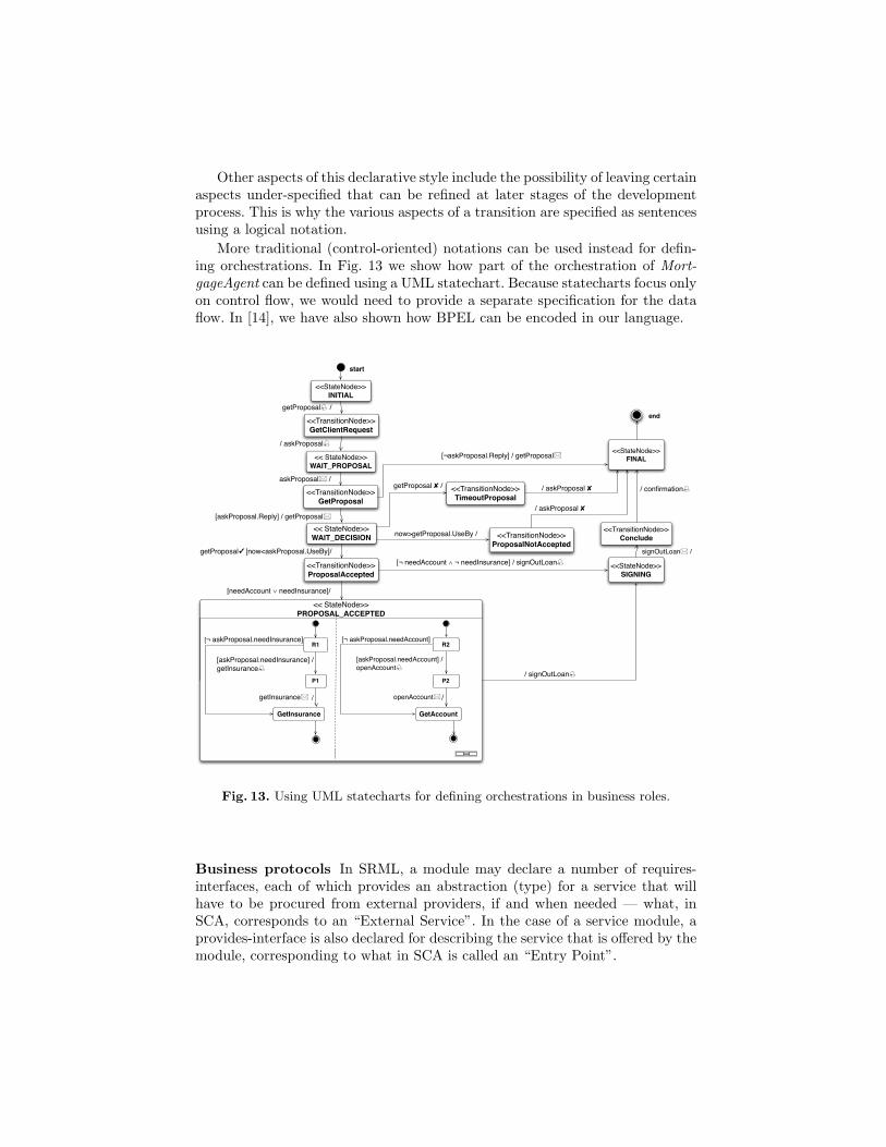
Other aspects of this declarative style include the possibility of leaving certainaspects under-specified that can be refined at later stages of the developmentprocess. This is why the various aspects of a transition are specified as sentencesusing a logical notation.
More traditional (control-oriented) notations can be used instead for defin-ing orchestrations. In Fig. 13 we show how part of the orchestration of Mort-gageAgent can be defined using a UML statechart. Because statecharts focus onlyon control flow, we would need to provide a separate specification for the dataflow. In [14], we have also shown how BPEL can be encoded in our language.
<< StateNode>>PROPOSAL_ACCEPTED
start
/ askProposal
<<StateNode>>INITIAL
<< StateNode>>WAIT_PROPOSAL
<< StateNode>>WAIT_DECISION
askProposal /
<<StateNode>>FINAL
/ askProposal ✘
<<StateNode>>SIGNING
/ signOutLoan
end
[askProposal.needInsurance] / getInsurance
[askProposal.needAccount] / openAccount
getInsurance / openAccount/
[¬ askProposal.needAccount]
[askProposal.Reply] / getProposal
now>getProposal.UseBy /
[¬ askProposal.needInsurance]
<<TransitionNode>>GetClientRequest
getProposal /
<<TransitionNode>>GetProposal
[¬askProposal.Reply] / getProposal
<<TransitionNode>>TimeoutProposal
/ askProposal ✘
<<TransitionNode>>ProposalNotAccepted
<<TransitionNode>>ProposalAccepted
getProposal✓ [now<askProposal.UseBy]/
[needAccount ∨ needInsurance]/
[¬ needAccount ∧ ¬ needInsurance] / signOutLoan
<<TransitionNode>>Conclude
signOutLoan /
/ confirmation getProposal ✘ /
R1
P1
GetInsurance
R2
P2
GetAccount
Fig. 13. Using UML statecharts for defining orchestrations in business roles.
Business protocols In SRML, a module may declare a number of requires-interfaces, each of which provides an abstraction (type) for a service that willhave to be procured from external providers, if and when needed — what, inSCA, corresponds to an “External Service”. In the case of a service module, aprovides-interface is also declared for describing the service that is offered by themodule, corresponding to what in SCA is called an “Entry Point”.
Both types of external interfaces are typed with what we call business pro-tocols, or just protocols if it is clear from the context what kind of protocols weare addressing. Like business roles, protocols include a signature. The differenceis that, instead of an orchestration, we provide a set of properties. In the caseof a requires-interface, these are the properties required of the external servicethat needs to be procured. In the case of a provides-interface, we specify theproperties offered by the service orchestrated by the module.
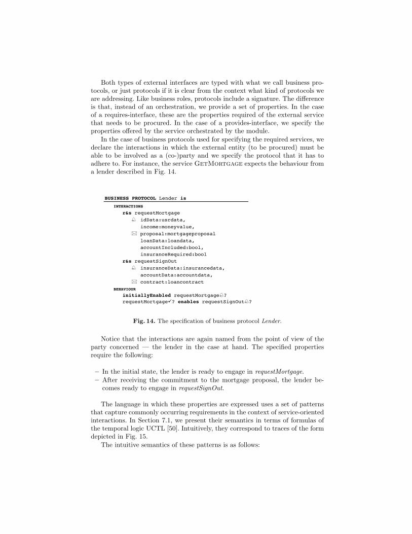
In the case of business protocols used for specifying the required services, wedeclare the interactions in which the external entity (to be procured) must beable to be involved as a (co-)party and we specify the protocol that it has toadhere to. For instance, the service GetMortgage expects the behaviour froma lender described in Fig. 14.
– 6 –
∧ signOutLoan.accountData=accountData
transition GetInsurance triggeredBy getInsurance guardedBy s=PROPOSAL_ACCEPTED effects needInsurance’=false ∧ ¬needAccount ⊃ s’=SIGNING ∧ insuranceData=getInsurance.insuranceData sends ¬needAccount ⊃ signOutLoan ∧ signOutLoan.insuranceData=insuranceData ∧ signOutLoan.accountData=accountData
transition Conclude triggeredBy signOutLoan guardedBy s=SIGNING effects s’=FINAL sends confirmation ∧ confirmation.contract=signOutLoan.contract ∧ regContract(askProposal.loanData,signOutLoan.contract)
BUSINESS PROTOCOL Lender is
INTERACTIONS r&s requestMortgage idData:usrdata,
income:moneyvalue, proposal:mortgageproposal loanData:loandata, accountIncluded:bool, insuranceRequired:bool r&s requestSignOut insuranceData:insurancedata, accountData:accountdata, contract:loancontract BEHAVIOUR initiallyEnabled requestMortgage?
requestMortgage? enables requestSignOut?
BUSINESS PROTOCOL Bank is
INTERACTIONS r&s newMortgageAccount idData:usrdata, loanData:loandata, accountData:accountdata
BEHAVIOUR initiallyEnabled newMortgageAccount? newMortgageAccount.Reply after newMortgageAccount!
Fig. 14. The specification of business protocol Lender.
Notice that the interactions are again named from the point of view of theparty concerned — the lender in the case at hand. The specified propertiesrequire the following:
– In the initial state, the lender is ready to engage in requestMortgage.– After receiving the commitment to the mortgage proposal, the lender be-
comes ready to engage in requestSignOut.
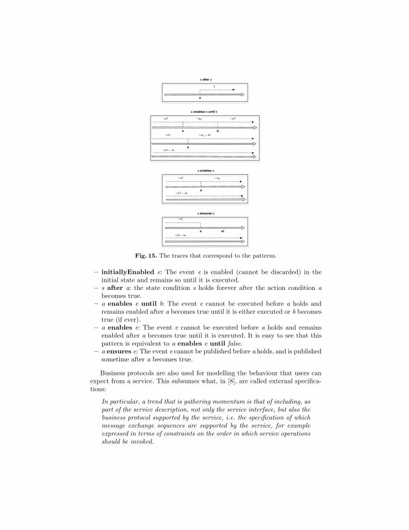
The language in which these properties are expressed uses a set of patternsthat capture commonly occurring requirements in the context of service-orientedinteractions. In Section 7.1, we present their semantics in terms of formulas ofthe temporal logic UCTL [50]. Intuitively, they correspond to traces of the formdepicted in Fig. 15.
The intuitive semantics of these patterns is as follows:
¬ e?
a
¬ e¿
¬ e? ∧ ¬a
a enables e
¬ e!
a e!¬ e! ∧ ¬a
a ensures e
s after a
s
a
¬ e?
a
¬ e¿
b
¬ e?
a enables e until b
¬ e?
a
¬ e¿ ∧ ¬b
¬ e? ∧ ¬a
Fig. 15. The traces that correspond to the patterns.
– initiallyEnabled e: The event e is enabled (cannot be discarded) in theinitial state and remains so until it is executed.
– s after a: the state condition s holds forever after the action condition abecomes true.
– a enables e until b: The event e cannot be executed before a holds andremains enabled after a becomes true until it is either executed or b becomestrue (if ever).
– a enables e: The event e cannot be executed before a holds and remainsenabled after a becomes true until it is executed. It is easy to see that thispattern is equivalent to a enables e until false.
– a ensures e: The event e cannot be published before a holds, and is publishedsometime after a becomes true.
Business protocols are also used for modelling the behaviour that users canexpect from a service. This subsumes what, in [8], are called external specifica-tions:
In particular, a trend that is gathering momentum is that of including, aspart of the service description, not only the service interface, but also thebusiness protocol supported by the service, i.e. the specification of whichmessage exchange sequences are supported by the service, for exampleexpressed in terms of constraints on the order in which service operationsshould be invoked.
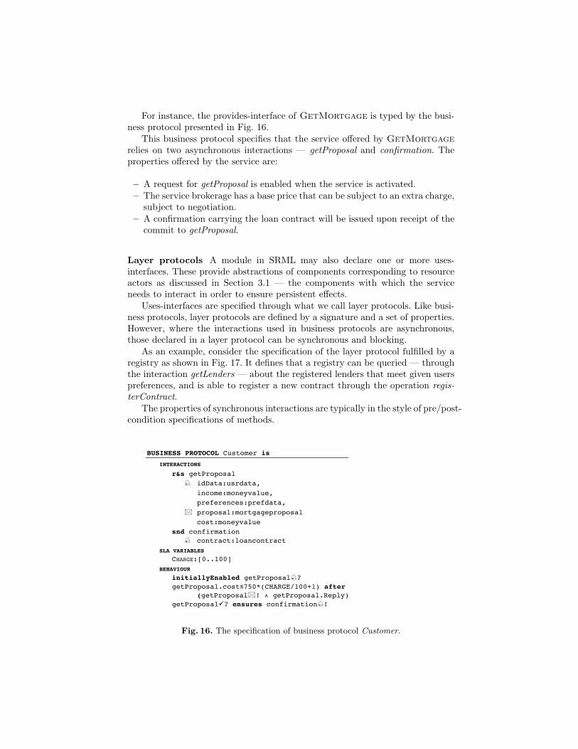
For instance, the provides-interface of GetMortgage is typed by the busi-ness protocol presented in Fig. 16.
This business protocol specifies that the service offered by GetMortgagerelies on two asynchronous interactions — getProposal and confirmation. Theproperties offered by the service are:
– A request for getProposal is enabled when the service is activated.– The service brokerage has a base price that can be subject to an extra charge,
subject to negotiation.– A confirmation carrying the loan contract will be issued upon receipt of the
commit to getProposal.
Layer protocols A module in SRML may also declare one or more uses-interfaces. These provide abstractions of components corresponding to resourceactors as discussed in Section 3.1 — the components with which the serviceneeds to interact in order to ensure persistent effects.
Uses-interfaces are specified through what we call layer protocols. Like busi-ness protocols, layer protocols are defined by a signature and a set of properties.However, where the interactions used in business protocols are asynchronous,those declared in a layer protocol can be synchronous and blocking.
As an example, consider the specification of the layer protocol fulfilled by aregistry as shown in Fig. 17. It defines that a registry can be queried — throughthe interaction getLenders — about the registered lenders that meet given userspreferences, and is able to register a new contract through the operation regis-terContract.
The properties of synchronous interactions are typically in the style of pre/post-condition specifications of methods.
– 7 –
BUSINESS PROTOCOL Insurance is
INTERACTIONS r&s newMortgageInsurance idData:usrdata, loanData:loandata, insuranceData:insurancedata
BEHAVIOUR initiallyEnabled newMortgageInsurance? newMortgageInsurance.Reply after newMortgageInsurance!
BUSINESS PROTOCOL Customer is
INTERACTIONS r&s getProposal idData:usrdata, income:moneyvalue, preferences:prefdata, proposal:mortgageproposal cost:moneyvalue
snd confirmation contract:loancontract SLA VARIABLES CHARGE:[0..100] BEHAVIOUR initiallyEnabled getProposal? getProposal.cost≤750*(CHARGE/100+1) after (getProposal! ∧ getProposal.Reply) getProposal? ensures confirmation!
END SPECIFICATIONS
Fig. 16. The specification of business protocol Customer.
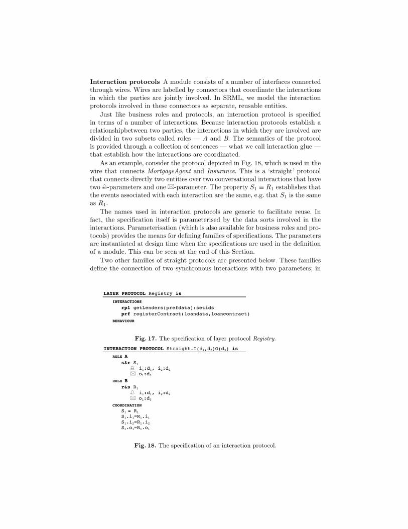
Interaction protocols A module consists of a number of interfaces connectedthrough wires. Wires are labelled by connectors that coordinate the interactionsin which the parties are jointly involved. In SRML, we model the interactionprotocols involved in these connectors as separate, reusable entities.
Just like business roles and protocols, an interaction protocol is specifiedin terms of a number of interactions. Because interaction protocols establish arelationshipbetween two parties, the interactions in which they are involved aredivided in two subsets called roles — A and B. The semantics of the protocolis provided through a collection of sentences — what we call interaction glue —that establish how the interactions are coordinated.
As an example, consider the protocol depicted in Fig. 18, which is used in thewire that connects MortgageAgent and Insurance. This is a ‘straight’ protocolthat connects directly two entities over two conversational interactions that havetwo -parameters and one � -parameter. The property S1 ≡ R1 establishes thatthe events associated with each interaction are the same, e.g. that S1 is the sameas R1.
The names used in interaction protocols are generic to facilitate reuse. Infact, the specification itself is parameterised by the data sorts involved in theinteractions. Parameterisation (which is also available for business roles and pro-tocols) provides the means for defining families of specifications. The parametersare instantiated at design time when the specifications are used in the definitionof a module. This can be seen at the end of this Section.
Two other families of straight protocols are presented below. These familiesdefine the connection of two synchronous interactions with two parameters; in
– 4 –
SPECIFICATIONS
LAYER PROTOCOL Registry is
INTERACTIONS rpl getLenders(prefdata):setids prf registerContract(loandata,loancontract) BEHAVIOUR
BUSINESS ROLE MortgageAgent is
INTERACTIONS r&s getProposal idData:usrdata, income:moneyvalue, preferences:prefdata, proposal:mortgageproposal cost:moneyvalue
s&r askProposal idData:usrdata,
income:moneyvalue, proposal:mortgageproposal loanData:loandata, accountIncluded:bool, insuranceRequired:bool s&r getInsurance idData:usrdata, loanData:loandata, insuranceData:insurancedata s&r openAccount idData:usrdata, loanData:loandata, accountData:accountdata s&r signOutLoan insuranceData:insurancedata, accountData:accountdata, contract:loancontract snd confirmation
contract:loancontract ask getLenders(prefdata):setids tll regContract(loandata,loancontract)
SLA VARIABLES CHARGE:[0..100]
ORCHESTRATION
local s:[INITIAL, WAIT_PROPOSAL, WAIT_DECISION, PROPOSAL_ACCEPTED, SIGNING, FINAL], lenders:setids, needAccount, needInsurance:bool, insuranceData:insurancedata, accountData:accountdata
Fig. 17. The specification of layer protocol Registry.
– 25 –
As an example, consider the following specification of the layer protocol fulfilled by a registry. It defines that a registry can be queried – through the interaction getLenders – about the registered lenders that meet given users preferences, and is able to register a new contract through the operation registerContract.
LAYER PROTOCOL Registry is
INTERACTIONS rpl getLenders(prefdata):setids prf registerContract(loandata,loancontract)
The properties of synchronous interactions are typically in the style of pre/post-condition specifications of methods.
5.1.5 Interaction protocols
A module consists of a number of interfaces connected through wires. Wires are labelled by connectors that coordinate the interactions in which the parties are jointly involved. In SRML, we model the interaction protocols involved in these connectors as separate, reusable entities.
Just like business roles and protocols, an interaction protocol is specified in terms of a number of interactions. Because interaction protocols establish a relationship between two parties, the interactions in which they are involved are divided in two subsets called roles – A and B. The semantics of the protocol is provided through a collection of sentences – what we call interaction glue – that establish how the inter-actions are coordinated. This may include routing events, superposing protocols for secure communication, or transforming sent data to the format expected by the re-ceiver, inter alia.
As an example, consider the following protocol used in the wire that connects MortgageAgent and Insurance:
INTERACTION PROTOCOL Straight.I(d1,d2)O(d3) is
ROLE A s&r S1
i1:d1, i2:d2 o1:d3
ROLE B r&s R1
i1:d1, i2:d2 o1:d3
COORDINATION S1 ≡ R1 S1.i1=R1.i1 S1.i2=R1.i2 S1.o1=R1.o1
This is a ‘straight’ protocol that connects directly two entities over two conversa-tional interactions that have two -parameters and one -parameter. The property S1 ≡ R1 establishes that the events associated with each interaction are the same, for example that S1 is the same as R1.
Fig. 18. The specification of an interaction protocol.
the first protocol, the interaction involves a return value. The first interactionprotocol establishes that the values returned by the synchronous interaction arethe same, while the second protocol synchronises the two operations without anyconversion of data.
Interaction protocols are first-class objects that can be (re)used to assignproperties to wires, which reflect constraints on the underlying run-time en-vironment. These may concern data transmission, synchronous/asynchronousconnectivity, distribution, and other non-functional properties such as security.In such cases, the specifications are not as simple as those of straight protocols.
Connectors After having chosen the protocols that coordinate the interactionsbetween two parties, we use them as the ‘glue’ (in the sense of [47]) of the con-nectors that label the wires that link the corresponding parties. In a connector,the interaction protocol is bound to the parties via ‘attachments’: these are map-pings from the roles to the signatures of the parties identifying which interactionsof the parties perform which roles in the protocol. The use of attachments al-lows us to separate the definition of the interaction protocols from their use inthe wires, which promotes reuse: typically, one defines a connector by choosingfrom a repository of (types of) protocols that have proved to be useful in othersituations.
Summarising, connectors are triples 〈µA, P, µB〉 where:
– P is an interaction protocol. We use roleAP and roleBP to designate itsroles and glueP for the role.
– µA and µB are attachments that connect the roles of the protocol to the sig-natures of the entities (business roles, business protocols or layer protocols)being interconnected.
– 26 –
The names used in interaction protocols are generic to facilitate reuse. In fact, the specification itself is parameterised by the data sorts involved in the interactions. Parameterisation (which is also available for business roles and protocols) provides the means for defining families of specifications. The parameters are instantiated at design time when the specifications are used in the definition of a module. This can be seen in Section 5.1.6.
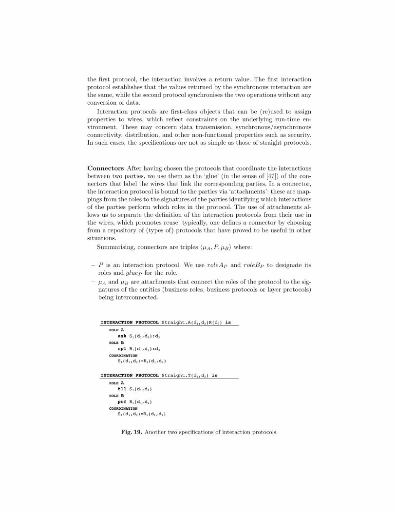
Two other families of straight protocols are presented below. These families de-fine the connection of two synchronous interactions with two parameters; in the first protocol, the interaction involves a return value.
INTERACTION PROTOCOL Straight.A(d1,d2)R(d3) is
ROLE A ask S1(d1,d2):d3
ROLE B rpl R1(d1,d2):d3
COORDINATION S1(d1,d2)=R1(d1,d2)
INTERACTION PROTOCOL Straight.T(d1,d2) is
ROLE A tll S1(d1,d2)
ROLE B prf R1(d1,d2)
COORDINATION S1(d1,d2)≡R1(d1,d2)
The first interaction protocol establishes that the values returned by the synchro-nous interaction are the same, while the second protocol synchronises the two oper-ations without any conversion of data.
Interaction protocols are first-class objects that can be (re)used to assign properties to wires, which reflect constraints on the underlying run-time environment. These may concern data transmission, synchronous/asynchronous connectivity, distribution, and other non-functional properties such as security. In such cases, the specifications are not as simple as those of straight protocols.
5.1.6 Connectors
After having chosen the protocols that coordinate the interactions between two par-ties, we use them as the ‘glue’ (in the sense of [56]) of the connectors that label the wires that link the corresponding parties. In a connector, the interaction protocol is bound to the parties via ‘attachments’: these are mappings from the roles to the signa-tures of the parties identifying which interactions of the parties perform which roles in the protocol. The use of attachments allows us to separate the definition of the inter-action protocols from their use in the wires, which promotes reuse: typically, one defines a connector by choosing from a repository of (types of) protocols that have proved to be useful in other situations.
Summarising, connectors are triples <μA,P,μB> where:
Fig. 19. Another two specifications of interaction protocols.
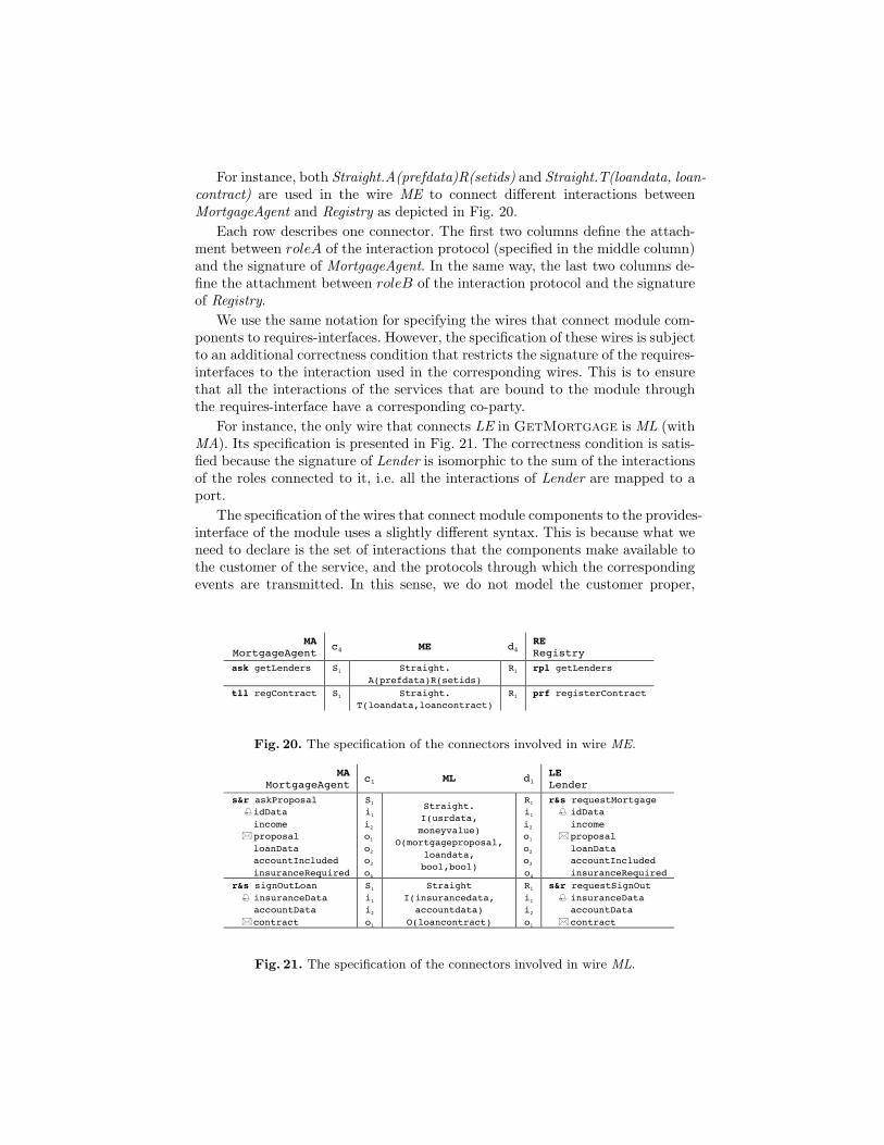
For instance, both Straight.A(prefdata)R(setids) and Straight.T(loandata, loan-contract) are used in the wire ME to connect different interactions betweenMortgageAgent and Registry as depicted in Fig. 20.
Each row describes one connector. The first two columns define the attach-ment between roleA of the interaction protocol (specified in the middle column)and the signature of MortgageAgent. In the same way, the last two columns de-fine the attachment between roleB of the interaction protocol and the signatureof Registry.
We use the same notation for specifying the wires that connect module com-ponents to requires-interfaces. However, the specification of these wires is subjectto an additional correctness condition that restricts the signature of the requires-interfaces to the interaction used in the corresponding wires. This is to ensurethat all the interactions of the services that are bound to the module throughthe requires-interface have a corresponding co-party.
For instance, the only wire that connects LE in GetMortgage is ML (withMA). Its specification is presented in Fig. 21. The correctness condition is satis-fied because the signature of Lender is isomorphic to the sum of the interactionsof the roles connected to it, i.e. all the interactions of Lender are mapped to aport.
The specification of the wires that connect module components to the provides-interface of the module uses a slightly different syntax. This is because what weneed to declare is the set of interactions that the components make available tothe customer of the service, and the protocols through which the correspondingevents are transmitted. In this sense, we do not model the customer proper,
– 3 –
WIRES
MA
MortgageAgent c4 ME d4
RE Registry
ask getLenders S1 Straight. A(prefdata)R(setids)
R1 rpl getLenders
tll regContract
S1
Straight. T(loandata,loancontract)
R1
prf registerContract
MA
MortgageAgent c1 MB d1 BA Bank
s&r openAccount idData loanData accountData
S1
i1 i2
o1
Straight. I(usrdata, loandata)
O(accountdata)
R1
i1 i2
o1
r&s newMortgageAccount idData loanData accountData
MA
MortgageAgent c1 MI d1
IN Insurance
s&r getInsurance idData loanData insuranceData
S1
i1 i2
o1
Straight. I(usrdata, loandata)
O(insurancedata)
R1
i1 i2
o1
r&s newMortgageInsurance idData loanData insuranceData
MA
MortgageAgent c1 ML d1
LE Lender
s&r askProposal idData income proposal loanData accountIncluded insuranceRequired
S1
i1 i2
o1
o2
o3
o4
Straight. I(usrdata, moneyvalue)
O(mortgageproposal, loandata, bool,bool)
R1
i1 i2
o1
o2
o3
o4
r&s requestMortgage idData income proposal loanData accountIncluded insuranceRequired
r&s signOutLoan insuranceData accountData contract
S1
i1 i2
o1
Straight I(insurancedata,
accountdata) O(loancontract)
R1
i1 i2
o1
s&r requestSignOut insuranceData accountData contract
c1 CM d1
MA MortgageAgent
S1
i1 i2
i3
o1
o2
Straight. I(usrdata,
moneyvalue,prefdata) O(mortageproposal,
moneyvalue)
R1
i1 i2
i3
o1
o2
r&s getProposal idData income preferences proposal cost
R1
i1 Straight
O(loancontract)
S1
i1 snd confirmation contract
END MODULE
Fig. 20. The specification of the connectors involved in wire ME.
– 3 –
ask getLenders S1 Straight. A(prefdata)R(setids)
R1 rpl getLenders
tll regContract
S1
Straight. T(loandata,loancontract)
R1
prf registerContract
MA
MortgageAgent c1 MB d1
BA Bank
s&r openAccount idData loanData accountData
S1
i1 i2
o1
Straight. I(usrdata, loandata)
O(accountdata)
R1
i1 i2
o1
r&s newMortgageAccount idData loanData accountData
MA
MortgageAgent c1 MI d1
IN Insurance
s&r getInsurance idData loanData insuranceData
S1
i1 i2
o1
Straight. I(usrdata, loandata)
O(insurancedata)
R1
i1 i2
o1
r&s newMortgageInsurance idData loanData insuranceData
MA
MortgageAgent c1 ML d1 LE Lender
s&r askProposal idData income proposal loanData accountIncluded insuranceRequired
S1
i1 i2
o1
o2
o3
o4
Straight. I(usrdata, moneyvalue)
O(mortgageproposal, loandata, bool,bool)
R1
i1 i2
o1
o2
o3
o4
r&s requestMortgage idData income proposal loanData accountIncluded insuranceRequired
r&s signOutLoan insuranceData accountData contract
S1
i1 i2
o1
Straight I(insurancedata,
accountdata) O(loancontract)
R1
i1 i2
o1
s&r requestSignOut insuranceData accountData contract
c1 CM d1
MA MortgageAgent
S1
i1 i2
i3
o1
o2
Straight. I(usrdata,
moneyvalue,prefdata) O(mortageproposal,
moneyvalue)
R1
i1 i2
i3
o1
o2
r&s getProposal idData income preferences proposal cost
R1
i1 Straight
O(loancontract)
S1
i1 snd confirmation contract
END MODULE
Fig. 21. The specification of the connectors involved in wire ML.
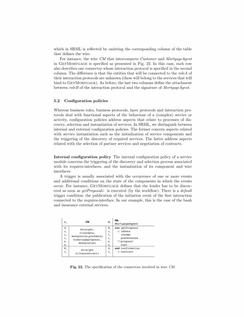
which in SRML is reflected by omitting the corresponding column of the tablethat defines the wire.
For instance, the wire CM that interconnects Customer and MortgageAgentin GetMortgage is specified as presented in Fig. 22. In this case, each rowalso describes one connector whose interaction protocol is specified in the secondcolumn. The difference is that the entities that will be connected to the roleA oftheir interaction protocols are unknown (these will belong to the services that willbind to GetMortgage). As before, the last two columns define the attachmentbetween roleB of the interaction protocol and the signature of MortgageAgent.
5.2 Configuration policies
Whereas business roles, business protocols, layer protocols and interaction pro-tocols deal with functional aspects of the behaviour of a (complex) service oractivity, configuration policies address aspects that relate to processes of dis-covery, selection and instantiation of services. In SRML, we distinguish betweeninternal and external configuration policies. The former concern aspects relatedwith service instantiation such as the initialization of service components andthe triggering of the discovery of required services. The latter address aspectsrelated with the selection of partner services and negotiation of contracts.
Internal configuration policy The internal configuration policy of a servicemodule concerns the triggering of the discovery and selection process associatedwith its requires-interfaces, and the instantiation of its component and wireinterfaces.
A trigger is usually associated with the occurrence of one or more eventsand additional conditions on the state of the components in which the eventsoccur. For instance, GetMortgage defines that the lender has to be discov-ered as soon as getProposal is executed (by the workflow). There is a defaulttrigger condition: the publication of the initiation event of the first interactionconnected to the requires-interface. In our example, this is the case of the bankand insurance external services.
– 3 –
ask getLenders S1 Straight. A(prefdata)R(setids)
R1 rpl getLenders
tll regContract
S1
Straight. T(loandata,loancontract)
R1
prf registerContract
MA
MortgageAgent c1 MB d1
BA Bank
s&r openAccount idData loanData accountData
S1
i1 i2
o1
Straight. I(usrdata, loandata)
O(accountdata)
R1
i1 i2
o1
r&s newMortgageAccount idData loanData accountData
MA
MortgageAgent c1 MI d1
IN Insurance
s&r getInsurance idData loanData insuranceData
S1
i1 i2
o1
Straight. I(usrdata, loandata)
O(insurancedata)
R1
i1 i2
o1
r&s newMortgageInsurance idData loanData insuranceData
MA
MortgageAgent c1 ML d1 LE Lender
s&r askProposal idData income proposal loanData accountIncluded insuranceRequired
S1
i1 i2
o1
o2
o3
o4
Straight. I(usrdata, moneyvalue)
O(mortgageproposal, loandata, bool,bool)
R1
i1 i2
o1
o2
o3
o4
r&s requestMortgage idData income proposal loanData accountIncluded insuranceRequired
r&s signOutLoan insuranceData accountData contract
S1
i1 i2
o1
Straight I(insurancedata,
accountdata) O(loancontract)
R1
i1 i2
o1
s&r requestSignOut insuranceData accountData contract
c1 CM d1
MA MortgageAgent
S1
i1 i2
i3
o1
o2
Straight. I(usrdata,
moneyvalue,prefdata) O(mortageproposal,
moneyvalue)
R1
i1 i2
i3
o1
o2
r&s getProposal idData income preferences proposal cost
R1
i1 Straight
O(loancontract)
S1
i1 snd confirmation contract
END MODULE
Fig. 22. The specification of the connectors involved in wire CM.
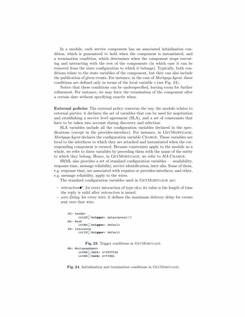
In a module, each service component has an associated initialisation con-dition, which is guaranteed to hold when the component is instantiated, anda termination condition, which determines when the component stops execut-ing and interacting with the rest of the components (in which case it can beremoved from the state configuration to which it belongs). Typically, both con-ditions relate to the state variables of the component, but they can also includethe publication of given events. For instance, in the case of MortgageAgent, theseconditions are defined only in terms of the local variable s (see Fig. 24).
Notice that these conditions can be underspecified, leaving room for furtherrefinement. For instance, we may force the termination of the component aftera certain date without specifying exactly when.
External policies The external policy concerns the way the module relates toexternal parties: it declares the set of variables that can be used for negotiationand establishing a service level agreement (SLA), and a set of constraints thathave to be taken into account during discovery and selection.
SLA variables include all the configuration variables declared in the spec-ifications (except in the provides-interface). For instance, in GetMortgage,MortgageAgent declares the configuration variable Charge. These variables arelocal to the interfaces to which they are attached and instantiated when the cor-responding component is created. Because constraints apply to the module as awhole, we refer to these variables by preceding them with the name of the entityto which they belong. Hence, in GetMortgage, we refer to MA.Charge.
SRML also provides a set of standard configuration variables — availability,response time, message reliability, service identification, inter alia. Some of them,e.g. response time, are associated with requires or provides-interfaces, and other,e.g. message reliability, apply to the wires.
The standard configuration variables used in GetMortgage are:
– interaction , for every interaction of type r&s; its value is the length of timethe reply is valid after interaction is issued.
– wire.Delay, for every wire; it defines the maximum delivery delay for eventssent over that wire.
– 2 –
REQUIRES
LE: Lender intLE trigger: getproposal? BA: Bank
intBA trigger: default IN: Insurance
intIN trigger: default
COMPONENTS
MA: MortgageAgent intMA init: s=INITIAL intMA term: s=FINAL
USES
RE: Registry
EXTERNAL POLICY
SLA VARIABLES MA.CHARGE, MA.getProposal, LE.ServiceId, LE.COST, LE.requestMortgage
CONSTRAINTS
C1: {MA.CHARGE,MA.getProposal}
def(c,t)=
€
1 if t ≤ 10 ∗c
1 + 2 ∗ c − 0.2 ∗ t if 10 ∗ c < t ≤ 5 + 10 ∗ c
0 otherwise
⎧
⎨ ⎪
⎩ ⎪
C2: {LE.ServiceId}
def(s)=
€
1 if s ∈ MA .lenders
0 otherwise
⎧ ⎨ ⎩
C3: {MA.getProposal,LE.requestMortgage},
def(t1,t2)=
€
1 if t2 > t1+ CM.Delay + ML.Delay
0 otherwise
⎧ ⎨ ⎩
C4: {LE.COST,LE.requestMortgage}
def(c,t)=
€
1
c+
t
100 if c < 500
0 otherwise
⎧ ⎨ ⎪
⎩ ⎪
WIRES
MA
MortgageAgent c4 ME d4
RE Registry
Fig. 23. Trigger conditions in GetMortgage.
– 2 –
BA: Bank intBA trigger: default
IN: Insurance intIN trigger: default
COMPONENTS
MA: MortgageAgent intMA init: s=INITIAL intMA term: s=FINAL
USES
RE: Registry
EXTERNAL POLICY
SLA VARIABLES MA.CHARGE, MA.getProposal, LE.ServiceId, LE.COST, LE.requestMortgage
CONSTRAINTS
C1: {MA.CHARGE,MA.getProposal}
def(c,t)=
€
1 if t ≤ 10 ∗c
1 + 2 ∗ c − 0.2 ∗ t if 10 ∗ c < t ≤ 5 + 10 ∗ c
0 otherwise
⎧
⎨ ⎪
⎩ ⎪
C2: {LE.ServiceId}
def(s)=
€
1 if s ∈ MA .lenders
0 otherwise
⎧ ⎨ ⎩
C3: {MA.getProposal,LE.requestMortgage},
def(t1,t2)=
€
1 if t2 > t1+ CM.Delay + ML.Delay
0 otherwise
⎧ ⎨ ⎩
C4: {LE.COST,LE.requestMortgage}
def(c,t)=
€
1
c+
t
100 if c < 500
0 otherwise
⎧ ⎨ ⎪
⎩ ⎪
WIRES
MA
MortgageAgent c4 ME d4
RE Registry
ask getLenders S1 Straight. A(prefdata)R(setids)
R1 rpl getLenders
tll regContract
S1
Straight. T(loandata,loancontract)
R1
prf registerContract
Fig. 24. Initialization and termination conditions in GetMortgage.
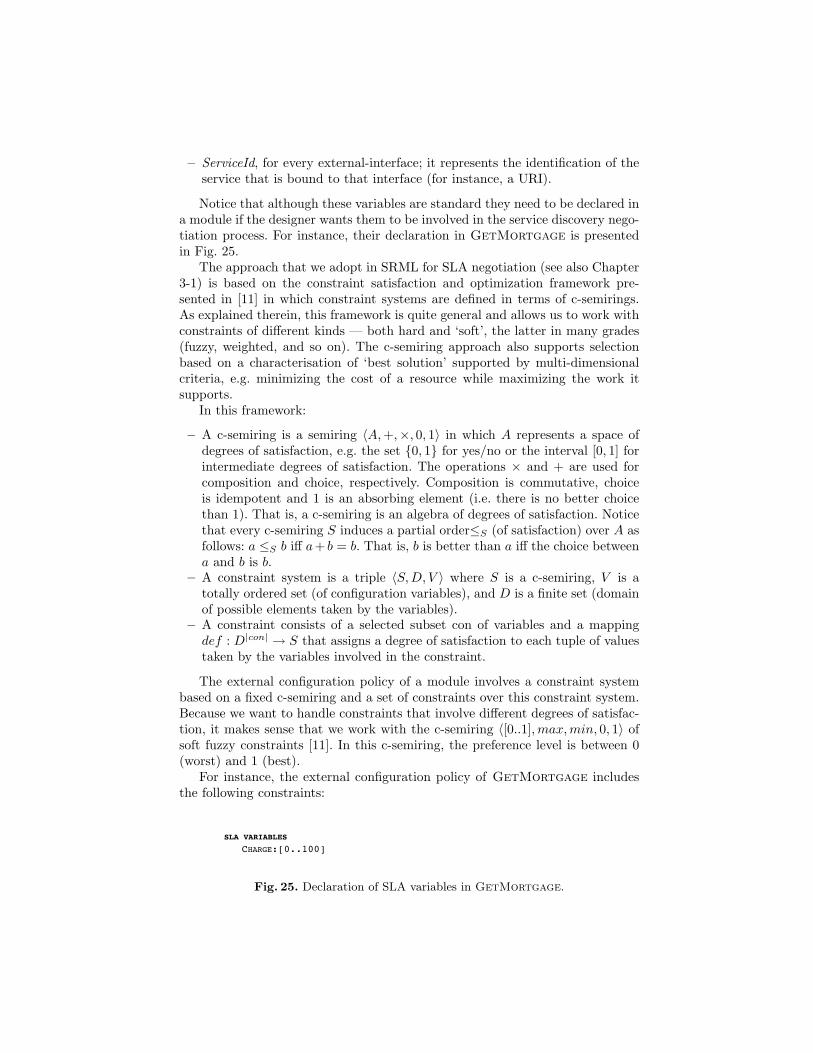
– ServiceId, for every external-interface; it represents the identification of theservice that is bound to that interface (for instance, a URI).
Notice that although these variables are standard they need to be declared ina module if the designer wants them to be involved in the service discovery nego-tiation process. For instance, their declaration in GetMortgage is presentedin Fig. 25.
The approach that we adopt in SRML for SLA negotiation (see also Chapter3-1) is based on the constraint satisfaction and optimization framework pre-sented in [11] in which constraint systems are defined in terms of c-semirings.As explained therein, this framework is quite general and allows us to work withconstraints of different kinds — both hard and ‘soft’, the latter in many grades(fuzzy, weighted, and so on). The c-semiring approach also supports selectionbased on a characterisation of ‘best solution’ supported by multi-dimensionalcriteria, e.g. minimizing the cost of a resource while maximizing the work itsupports.
In this framework:
– A c-semiring is a semiring 〈A,+,×, 0, 1〉 in which A represents a space ofdegrees of satisfaction, e.g. the set {0, 1} for yes/no or the interval [0, 1] forintermediate degrees of satisfaction. The operations × and + are used forcomposition and choice, respectively. Composition is commutative, choiceis idempotent and 1 is an absorbing element (i.e. there is no better choicethan 1). That is, a c-semiring is an algebra of degrees of satisfaction. Noticethat every c-semiring S induces a partial order≤S (of satisfaction) over A asfollows: a ≤S b iff a+ b = b. That is, b is better than a iff the choice betweena and b is b.
– A constraint system is a triple 〈S,D, V 〉 where S is a c-semiring, V is atotally ordered set (of configuration variables), and D is a finite set (domainof possible elements taken by the variables).
– A constraint consists of a selected subset con of variables and a mappingdef : D|con| → S that assigns a degree of satisfaction to each tuple of valuestaken by the variables involved in the constraint.
The external configuration policy of a module involves a constraint systembased on a fixed c-semiring and a set of constraints over this constraint system.Because we want to handle constraints that involve different degrees of satisfac-tion, it makes sense that we work with the c-semiring 〈[0..1],max,min, 0, 1〉 ofsoft fuzzy constraints [11]. In this c-semiring, the preference level is between 0(worst) and 1 (best).
For instance, the external configuration policy of GetMortgage includesthe following constraints:
– 4 –
SPECIFICATIONS
LAYER PROTOCOL Registry is
INTERACTIONS rpl getLenders(prefdata):setids prf registerContract(loandata,loancontract) BEHAVIOUR
BUSINESS ROLE MortgageAgent is
INTERACTIONS r&s getProposal idData:usrdata, income:moneyvalue, preferences:prefdata, proposal:mortgageproposal cost:moneyvalue
s&r askProposal idData:usrdata,
income:moneyvalue, proposal:mortgageproposal loanData:loandata, accountIncluded:bool, insuranceRequired:bool s&r getInsurance idData:usrdata, loanData:loandata, insuranceData:insurancedata s&r openAccount idData:usrdata, loanData:loandata, accountData:accountdata s&r signOutLoan insuranceData:insurancedata, accountData:accountdata, contract:loancontract snd confirmation
contract:loancontract ask getLenders(prefdata):setids tll regContract(loandata,loancontract)
SLA VARIABLES CHARGE:[0..100]
ORCHESTRATION
local s:[INITIAL, WAIT_PROPOSAL, WAIT_DECISION, PROPOSAL_ACCEPTED, SIGNING, FINAL], lenders:setids, needAccount, needInsurance:bool, insuranceData:insurancedata, accountData:accountdata
Fig. 25. Declaration of SLA variables in GetMortgage.
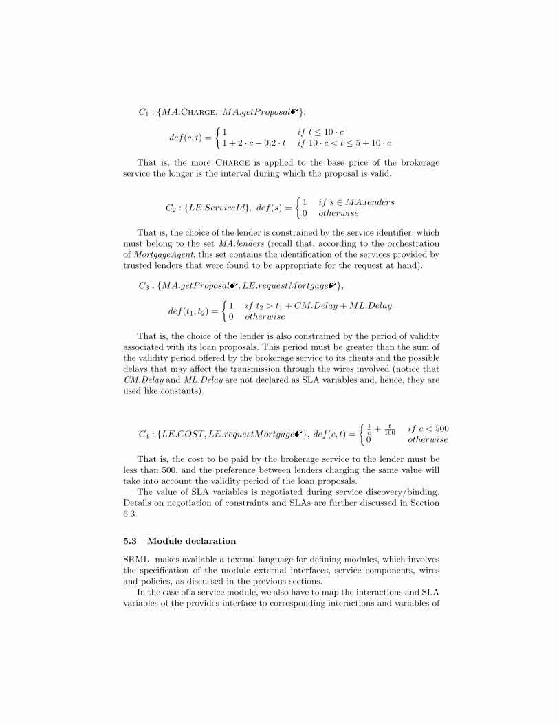
C1 : {MA.Charge, MA.getProposal },
def(c, t) ={
1 if t ≤ 10 · c1 + 2 · c− 0.2 · t if 10 · c < t ≤ 5 + 10 · c
That is, the more Charge is applied to the base price of the brokerageservice the longer is the interval during which the proposal is valid.
C2 : {LE.ServiceId}, def(s) ={
1 if s ∈MA.lenders0 otherwise
That is, the choice of the lender is constrained by the service identifier, whichmust belong to the set MA.lenders (recall that, according to the orchestrationof MortgageAgent, this set contains the identification of the services provided bytrusted lenders that were found to be appropriate for the request at hand).
C3 : {MA.getProposal , LE.requestMortgage },
def(t1, t2) ={
1 if t2 > t1 + CM.Delay +ML.Delay0 otherwise
That is, the choice of the lender is also constrained by the period of validityassociated with its loan proposals. This period must be greater than the sum ofthe validity period offered by the brokerage service to its clients and the possibledelays that may affect the transmission through the wires involved (notice thatCM.Delay and ML.Delay are not declared as SLA variables and, hence, they areused like constants).
C4 : {LE.COST,LE.requestMortgage }, def(c, t) ={
1c + t
100 if c < 5000 otherwise
That is, the cost to be paid by the brokerage service to the lender must beless than 500, and the preference between lenders charging the same value willtake into account the validity period of the loan proposals.
The value of SLA variables is negotiated during service discovery/binding.Details on negotiation of constraints and SLAs are further discussed in Section6.3.
5.3 Module declaration
SRML makes available a textual language for defining modules, which involvesthe specification of the module external interfaces, service components, wiresand policies, as discussed in the previous sections.
In the case of a service module, we also have to map the interactions and SLAvariables of the provides-interface to corresponding interactions and variables of
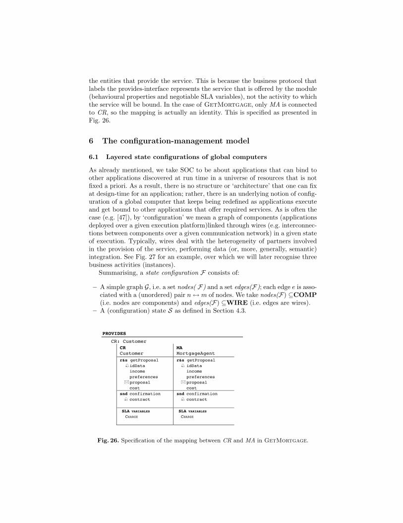
the entities that provide the service. This is because the business protocol thatlabels the provides-interface represents the service that is offered by the module(behavioural properties and negotiable SLA variables), not the activity to whichthe service will be bound. In the case of GetMortgage, only MA is connectedto CR, so the mapping is actually an identity. This is specified as presented inFig. 26.
6 The configuration-management model
6.1 Layered state configurations of global computers
As already mentioned, we take SOC to be about applications that can bind toother applications discovered at run time in a universe of resources that is notfixed a priori. As a result, there is no structure or ‘architecture’ that one can fixat design-time for an application; rather, there is an underlying notion of config-uration of a global computer that keeps being redefined as applications executeand get bound to other applications that offer required services. As is often thecase (e.g. [47]), by ‘configuration’ we mean a graph of components (applicationsdeployed over a given execution platform)linked through wires (e.g. interconnec-tions between components over a given communication network) in a given stateof execution. Typically, wires deal with the heterogeneity of partners involvedin the provision of the service, performing data (or, more, generally, semantic)integration. See Fig. 27 for an example, over which we will later recognise threebusiness activities (instances).
Summarising, a state configuration F consists of:
– A simple graph G, i.e. a set nodes( F) and a set edges(F); each edge e is asso-ciated with a (unordered) pair n↔ m of nodes. We take nodes(F) ⊆COMP(i.e. nodes are components) and edges(F) ⊆WIRE (i.e. edges are wires).
– A (configuration) state S as defined in Section 4.3.
– 1 –
Appendix B – The Example
MODULE GETMORTGAGE is
DATATYPES
sorts: usrdata, prefdata, moneyvalue, mortgageproposal, loandata, loancontract, insurancedata, accountdata, setids, bool, nat
PROVIDES
CR: Customer CR Customer
MA MortgageAgent
r&s getProposal idData income preferences proposal cost
r&s getProposal idData income preferences proposal cost
snd confirmation contract
snd confirmation contract
SLA VARIABLES CHARGE
SLA VARIABLES CHARGE
REQUIRES
LE: Lender intLE trigger: getproposal?
Fig. 26. Specification of the mapping between CR and MA in GetMortgage.
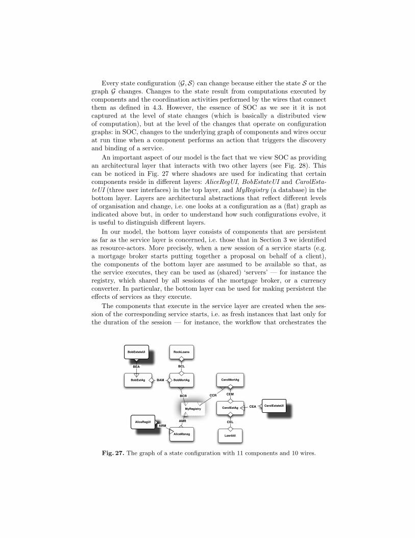
Every state configuration 〈G,S〉 can change because either the state S or thegraph G changes. Changes to the state result from computations executed bycomponents and the coordination activities performed by the wires that connectthem as defined in 4.3. However, the essence of SOC as we see it it is notcaptured at the level of state changes (which is basically a distributed viewof computation), but at the level of the changes that operate on configurationgraphs: in SOC, changes to the underlying graph of components and wires occurat run time when a component performs an action that triggers the discoveryand binding of a service.
An important aspect of our model is the fact that we view SOC as providingan architectural layer that interacts with two other layers (see Fig. 28). Thiscan be noticed in Fig. 27 where shadows are used for indicating that certaincomponents reside in different layers: AliceRegUI, BobEstateUI and CarolEsta-teUI (three user interfaces) in the top layer, and MyRegistry (a database) in thebottom layer. Layers are architectural abstractions that reflect different levelsof organisation and change, i.e. one looks at a configuration as a (flat) graph asindicated above but, in order to understand how such configurations evolve, itis useful to distinguish different layers.
In our model, the bottom layer consists of components that are persistentas far as the service layer is concerned, i.e. those that in Section 3 we identifiedas resource-actors. More precisely, when a new session of a service starts (e.g.a mortgage broker starts putting together a proposal on behalf of a client),the components of the bottom layer are assumed to be available so that, asthe service executes, they can be used as (shared) ‘servers’ — for instance theregistry, which shared by all sessions of the mortgage broker, or a currencyconverter. In particular, the bottom layer can be used for making persistent theeffects of services as they execute.
The components that execute in the service layer are created when the ses-sion of the corresponding service starts, i.e. as fresh instances that last only forthe duration of the session — for instance, the workflow that orchestrates the
CarolEstAgMyRegistry
AliceManag
RockLoans
BobMortAg
BCL
CarolMortAg
Law4All
CEL
BobEstateUI
AliceRegUIARM
BCR
AMR
CarolEstateUICEA
CCR CEM
BobEstAg
BEA
BAM
Fig. 27. The graph of a state configuration with 11 components and 10 wires.
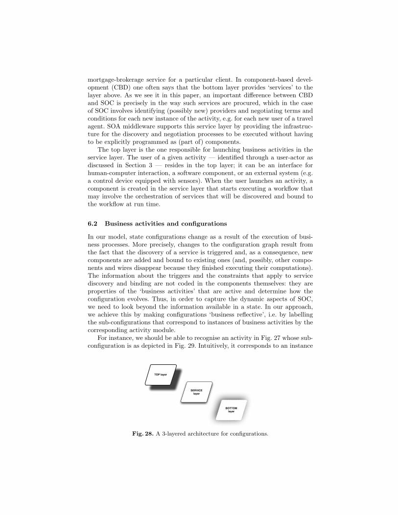
mortgage-brokerage service for a particular client. In component-based devel-opment (CBD) one often says that the bottom layer provides ‘services’ to thelayer above. As we see it in this paper, an important difference between CBDand SOC is precisely in the way such services are procured, which in the caseof SOC involves identifying (possibly new) providers and negotiating terms andconditions for each new instance of the activity, e.g. for each new user of a travelagent. SOA middleware supports this service layer by providing the infrastruc-ture for the discovery and negotiation processes to be executed without havingto be explicitly programmed as (part of) components.
The top layer is the one responsible for launching business activities in theservice layer. The user of a given activity — identified through a user-actor asdiscussed in Section 3 — resides in the top layer; it can be an interface forhuman-computer interaction, a software component, or an external system (e.g.a control device equipped with sensors). When the user launches an activity, acomponent is created in the service layer that starts executing a workflow thatmay involve the orchestration of services that will be discovered and bound tothe workflow at run time.
6.2 Business activities and configurations
In our model, state configurations change as a result of the execution of busi-ness processes. More precisely, changes to the configuration graph result fromthe fact that the discovery of a service is triggered and, as a consequence, newcomponents are added and bound to existing ones (and, possibly, other compo-nents and wires disappear because they finished executing their computations).The information about the triggers and the constraints that apply to servicediscovery and binding are not coded in the components themselves: they areproperties of the ‘business activities’ that are active and determine how theconfiguration evolves. Thus, in order to capture the dynamic aspects of SOC,we need to look beyond the information available in a state. In our approach,we achieve this by making configurations ‘business reflective’, i.e. by labellingthe sub-configurations that correspond to instances of business activities by thecorresponding activity module.
For instance, we should be able to recognise an activity in Fig. 27 whose sub-configuration is as depicted in Fig. 29. Intuitively, it corresponds to an instance
SERVICE layer
BOTTOM layer
TOP layer
Fig. 28. A 3-layered architecture for configurations.
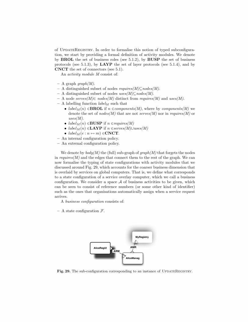
of UpdateRegistry. In order to formalise this notion of typed subconfigura-tion, we start by providing a formal definition of activity modules. We denoteby BROL the set of business roles (see 5.1.2), by BUSP the set of businessprotocols (see 5.1.3), by LAYP the set of layer protocols (see 5.1.4), and byCNCT the set of connectors (see 5.1).
An activity module M consist of:
– A graph graph(M).– A distinguished subset of nodes requires(M)⊆nodes(M).– A distinguished subset of nodes uses(M)⊆nodes(M).– A node serves(M)∈ nodes(M) distinct from requires(M) and uses(M).– A labelling function labelM such that• labelM (n) ∈BROL if n ∈components(M), where by components(M) we
denote the set of nodes(M) that are not serves(M) nor in requires(M) oruses(M).
• labelM (n) ∈BUSP if n ∈requires(M)• labelM (n) ∈LAYP if n ∈serves(M)∪uses(M)• labelM (e : n↔ m) ∈CNCT.
– An internal configuration policy.– An external configuration policy.
We denote by body(M) the (full) sub-graph of graph(M) that forgets the nodesin requires(M) and the edges that connect them to the rest of the graph. We cannow formalise the typing of state configurations with activity modules that wediscussed around Fig. 29, which accounts for the coarser business dimension thatis overlaid by services on global computers. That is, we define what correspondsto a state configuration of a service overlay computer, which we call a businessconfiguration. We consider a space A of business activities to be given, whichcan be seen to consist of reference numbers (or some other kind of identifier)such as the ones that organisations automatically assign when a service requestarrives.
A business configuration consists of:
– A state configuration F .
MyRegistry
AliceManag
AliceRegUIARM
AMR
Fig. 29. The sub-configuration corresponding to an instance of UpdateRegistry.
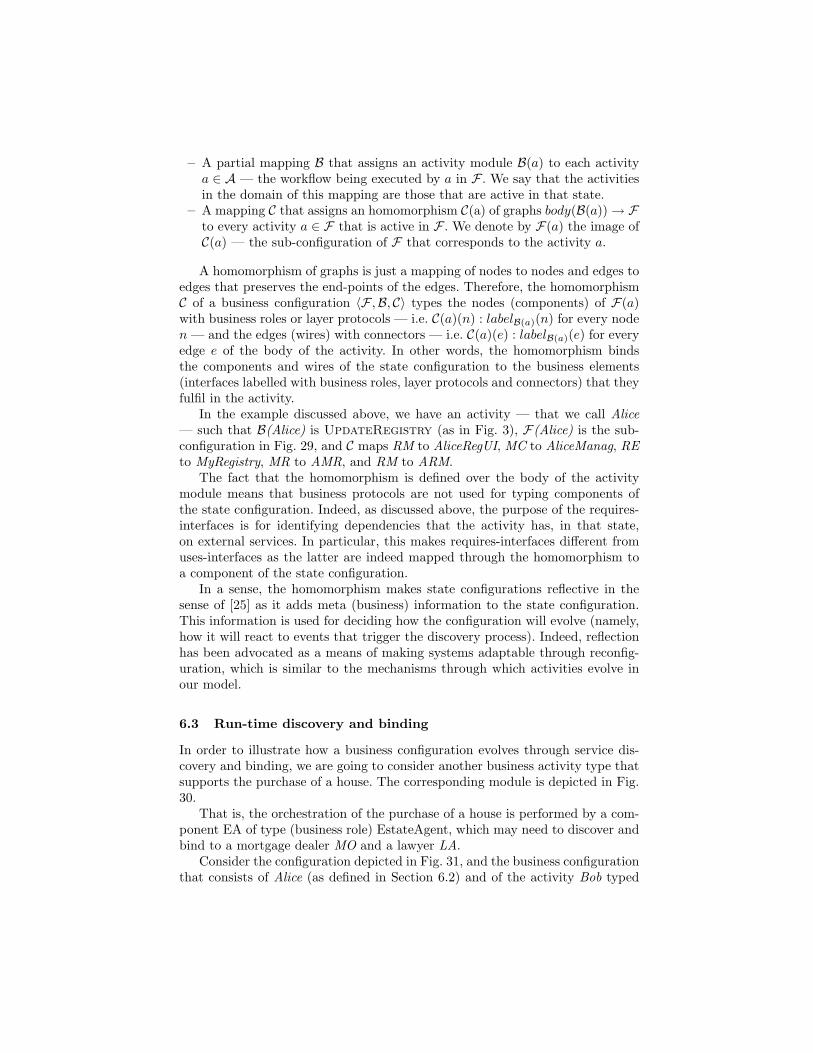
– A partial mapping B that assigns an activity module B(a) to each activitya ∈ A — the workflow being executed by a in F . We say that the activitiesin the domain of this mapping are those that are active in that state.
– A mapping C that assigns an homomorphism C(a) of graphs body(B(a))→ Fto every activity a ∈ F that is active in F . We denote by F(a) the image ofC(a) — the sub-configuration of F that corresponds to the activity a.
A homomorphism of graphs is just a mapping of nodes to nodes and edges toedges that preserves the end-points of the edges. Therefore, the homomorphismC of a business configuration 〈F ,B, C〉 types the nodes (components) of F(a)with business roles or layer protocols — i.e. C(a)(n) : labelB(a)(n) for every noden — and the edges (wires) with connectors — i.e. C(a)(e) : labelB(a)(e) for everyedge e of the body of the activity. In other words, the homomorphism bindsthe components and wires of the state configuration to the business elements(interfaces labelled with business roles, layer protocols and connectors) that theyfulfil in the activity.
In the example discussed above, we have an activity — that we call Alice— such that B(Alice) is UpdateRegistry (as in Fig. 3), F(Alice) is the sub-configuration in Fig. 29, and C maps RM to AliceRegUI, MC to AliceManag, REto MyRegistry, MR to AMR, and RM to ARM.
The fact that the homomorphism is defined over the body of the activitymodule means that business protocols are not used for typing components ofthe state configuration. Indeed, as discussed above, the purpose of the requires-interfaces is for identifying dependencies that the activity has, in that state,on external services. In particular, this makes requires-interfaces different fromuses-interfaces as the latter are indeed mapped through the homomorphism toa component of the state configuration.
In a sense, the homomorphism makes state configurations reflective in thesense of [25] as it adds meta (business) information to the state configuration.This information is used for deciding how the configuration will evolve (namely,how it will react to events that trigger the discovery process). Indeed, reflectionhas been advocated as a means of making systems adaptable through reconfig-uration, which is similar to the mechanisms through which activities evolve inour model.
6.3 Run-time discovery and binding
In order to illustrate how a business configuration evolves through service dis-covery and binding, we are going to consider another business activity type thatsupports the purchase of a house. The corresponding module is depicted in Fig.30.
That is, the orchestration of the purchase of a house is performed by a com-ponent EA of type (business role) EstateAgent, which may need to discover andbind to a mortgage dealer MO and a lawyer LA.
Consider the configuration depicted in Fig. 31, and the business configurationthat consists of Alice (as defined in Section 6.2) and of the activity Bob typed
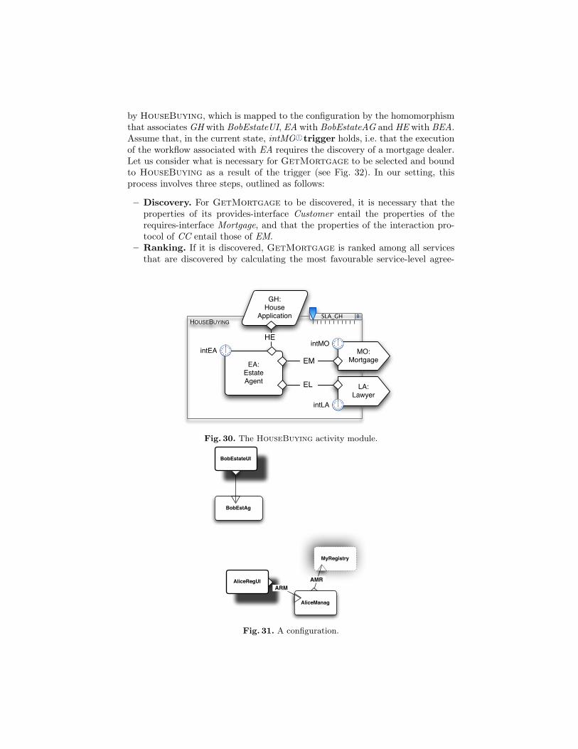
by HouseBuying, which is mapped to the configuration by the homomorphismthat associates GH with BobEstateUI, EA with BobEstateAG and HE with BEA.Assume that, in the current state, intMO trigger holds, i.e. that the executionof the workflow associated with EA requires the discovery of a mortgage dealer.Let us consider what is necessary for GetMortgage to be selected and boundto HouseBuying as a result of the trigger (see Fig. 32). In our setting, thisprocess involves three steps, outlined as follows:
– Discovery. For GetMortgage to be discovered, it is necessary that theproperties of its provides-interface Customer entail the properties of therequires-interface Mortgage, and that the properties of the interaction pro-tocol of CC entail those of EM.
– Ranking. If it is discovered, GetMortgage is ranked among all servicesthat are discovered by calculating the most favourable service-level agree-
HOUSEBUYINGSLA_GH
EA:EstateAgent
MO:Mortgage
intMO
EM
GH:House
Application
HEintEA
LA:Lawyer
intLA
EL
Fig. 30. The HouseBuying activity module.
MyRegistry
AliceManag
BobEstateUI
AliceRegUIARM
AMR
BobEstAg
Fig. 31. A configuration.
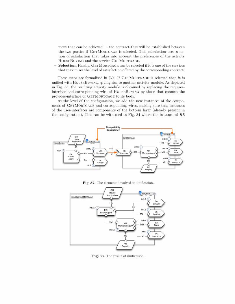
ment that can be achieved — the contract that will be established betweenthe two parties if GetMortgage is selected. This calculation uses a no-tion of satisfaction that takes into account the preferences of the activityHouseBuying and the service GetMortgage.
– Selection. Finally, GetMortgage can be selected if it is one of the servicesthat maximises the level of satisfaction offered by the corresponding contract.
These steps are formalised in [30]. If GetMortgage is selected then it isunified with HouseBuying, giving rise to another activity module. As depictedin Fig. 33, the resulting activity module is obtained by replacing the requires-interface and corresponding wire of HouseBuying by those that connect theprovides-interface of GetMortgage to its body.
At the level of the configuration, we add the new instances of the compo-nents of GetMortgage and corresponding wires, making sure that instancesof the uses-interfaces are components of the bottom layer (already present inthe configuration). This can be witnessed in Fig. 34 where the instance of RE
HOUSEBUYINGSLA_GH
EA:EstateAgent
MO:Mortgage
intMO
EM
GH:House
Application
HEintEA
LA:Lawyer
intLA
EL
GETMORTGAGE
SLA_GM
RE:Registry
MA:MortgageAgent
LE:Lender
intLE
BA:Bank
intBA
IN:Insurance
intIN
CM CR: Customer
ME
ML
MB
MI
intMA⊥
ρ
Compatibility Consistency
Fig. 32. The elements involved in unification.
HOUSEBUYINGMORTGAGE
LA:Lawyer
SLA_HBM
EA:EstateAgent
intLA
EL
GH:House
Application
HE
intEA
RE:Registry
MA:MortgageAgent
LE:Lender
intLE
BA:Bank
intBA
IN:Insurance
intIN
ME
ML
MB
MI
intMA
CM
Fig. 33. The result of unification.
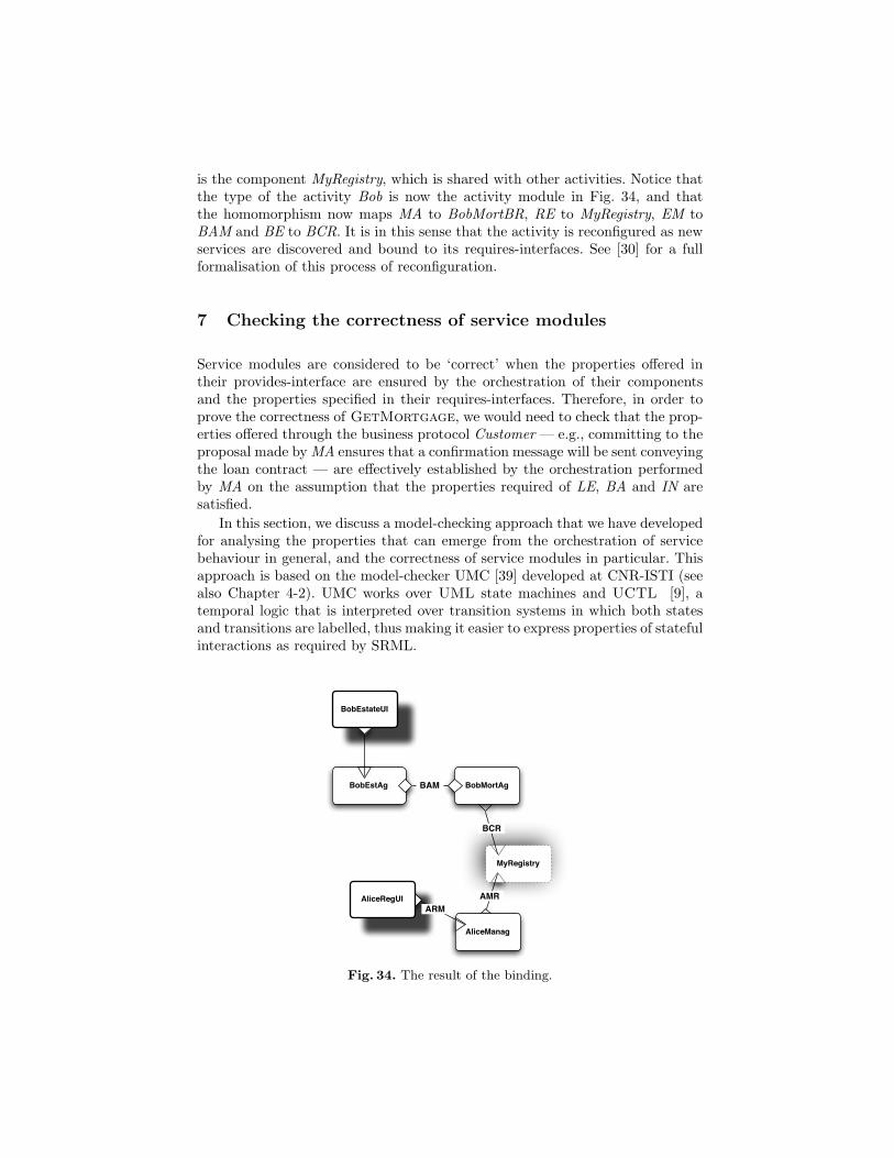
is the component MyRegistry, which is shared with other activities. Notice thatthe type of the activity Bob is now the activity module in Fig. 34, and thatthe homomorphism now maps MA to BobMortBR, RE to MyRegistry, EM toBAM and BE to BCR. It is in this sense that the activity is reconfigured as newservices are discovered and bound to its requires-interfaces. See [30] for a fullformalisation of this process of reconfiguration.
7 Checking the correctness of service modules
Service modules are considered to be ‘correct’ when the properties offered intheir provides-interface are ensured by the orchestration of their componentsand the properties specified in their requires-interfaces. Therefore, in order toprove the correctness of GetMortgage, we would need to check that the prop-erties offered through the business protocol Customer — e.g., committing to theproposal made by MA ensures that a confirmation message will be sent conveyingthe loan contract — are effectively established by the orchestration performedby MA on the assumption that the properties required of LE, BA and IN aresatisfied.
In this section, we discuss a model-checking approach that we have developedfor analysing the properties that can emerge from the orchestration of servicebehaviour in general, and the correctness of service modules in particular. Thisapproach is based on the model-checker UMC [39] developed at CNR-ISTI (seealso Chapter 4-2). UMC works over UML state machines and UCTL [9], atemporal logic that is interpreted over transition systems in which both statesand transitions are labelled, thus making it easier to express properties of statefulinteractions as required by SRML.
MyRegistry
AliceManag
BobMortAg
BobEstateUI
AliceRegUIARM
BCR
AMR
BobEstAg BAM
Fig. 34. The result of the binding.
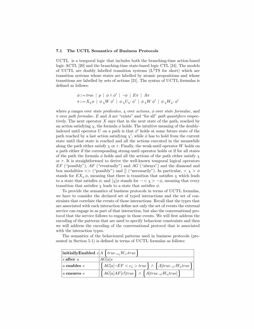
7.1 The UCTL Semantics of Business Protocols
UCTL is a temporal logic that includes both the branching-time action-basedlogic ACTL [20] and the branching-time state-based logic CTL [24]. The modelsof UCTL are doubly labelled transition systems (L2TS for short) which aretransition systems whose states are labelled by atomic propositions and whosetransitions are labelled by sets of actions [21]. The syntax of UCTL formulas isdefined as follows:
φ ::= true | p | φ ∧ φ′ | ¬φ | Eπ | Aππ ::=Xχφ | φ χW φ′ | φ χUχ′ φ′ | φ χW φ′ | φ χWχ′ φ′
where p ranges over state predicates, χ over actions, φ over state formulae, andπ over path formulae. E and A are “exists” and “for all” path quantifiers respec-tively. The next operator X says that in the next state of the path, reached byan action satisfying χ, the formula φ holds. The intuitive meaning of the doubly-indexed until operator U on a path is that φ′ holds at some future state of thepath reached by a last action satisfying χ′, while φ has to hold from the currentstate until that state is reached and all the actions executed in the meanwhilealong the path either satisfy χ or τ . Finally, the weak-until operator W holds ona path either if the corresponding strong-until operator holds or if for all statesof the path the formula φ holds and all the actions of the path either satisfy χor τ . It is straightforward to derive the well-known temporal logical operatorsEF (“possibly”), AF (“eventually”) and AG (“always”) and the diamond andbox modalities <> (“possibly”) and [] (“necessarily”). In particular, < χ > φstands for EXχ φ, meaning that there is transition that satisfies χ which leadsto a state that satisfies φ; and [χ]φ stands for ¬ < χ > ¬φ, meaning that everytransition that satisfies χ leads to a state that satisfies φ.
To provide the semantics of business protocols in terms of UCTL formulas,we have to consider the declared set of typed interactions and the set of con-straints that correlate the events of those interactions. Recall that the types thatare associated with each interaction define not only the set of events the externalservice can engage in as part of that interaction, but also the conversational pro-tocol that the service follows to engage in those events. We will first address theencoding of the patterns that are used to specify behaviour constraints and thenwe will address the encoding of the conversational protocol that is associatedwith the interaction types.
The semantics of the behavioural patterns used in business protocols (pre-sented in Section 5.1) is defined in terms of UCTL formulas as follows:
initiallyEnabled e Atrue¬e¿We?true
s after a AG[a]s
a enables eAG[a]¬EF < e¿ > true
∧A[true¬e?Watrue
a ensures eAG[a]AF [e!]true
∧A[true¬e!Watrue]
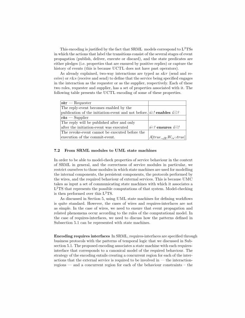
This encoding is justified by the fact that SRML models correspond to L2TSsin which the actions that label the transitions consist of the several stages of eventpropagation (publish, deliver, execute or discard), and the state predicates areeither pledges (i.e. properties that are ensured by positive replies) or capture thehistory of events (this is because UCTL does not have past operators).
As already explained, two-way interactions are typed as s&r (send and re-ceive) or r&s (receive and send) to define that the service being specified engagesin the interaction as the requester or as the supplier, respectively. Each of thesetwo roles, requester and supplier, has a set of properties associated with it. Thefollowing table presents the UCTL encoding of some of these properties.
s&r — RequesterThe reply-event becomes enabled by thepublication of the initiation-event and not before. i ! enables i� ?r&s — SupplierThe reply will be published after and onlyafter the initiation-event was executed i ? ensures i� !The revoke-event cannot be executed before theexecution of the commit-event. A[true¬i>?WiX?true]
7.2 From SRML modules to UML state machines
In order to be able to model-check properties of service behaviour in the contextof SRML in general, and the correctness of service modules in particular, werestrict ourselves to those modules in which state machines are used for modellingthe internal components, the persistent components, the protocols performed bythe wires, and the required behaviour of external services. This is because UMCtakes as input a set of communicating state machines with which it associates aL2TS that represents the possible computations of that system. Model-checkingis then performed over this L2TS.
As discussed in Section 5, using UML state machines for defining workflowsis quite standard. However, the cases of wires and requires-interfaces are notas simple. In the case of wires, we need to ensure that event propagation andrelated phenomena occur according to the rules of the computational model. Inthe case of requires-interfaces, we need to discuss how the patterns defined inSubsection 5.1 can be represented with state machines.
Encoding requires interfaces In SRML, requires-interfaces are specified throughbusiness protocols with the patterns of temporal logic that we discussed in Sub-section 5.1. The proposed encoding associates a state machine with each requires-interface that corresponds to a canonical model of the required behaviour. Thestrategy of the encoding entails creating a concurrent region for each of the inter-actions that the external service is required to be involved in — the interaction-regions — and a concurrent region for each of the behaviour constraints – the
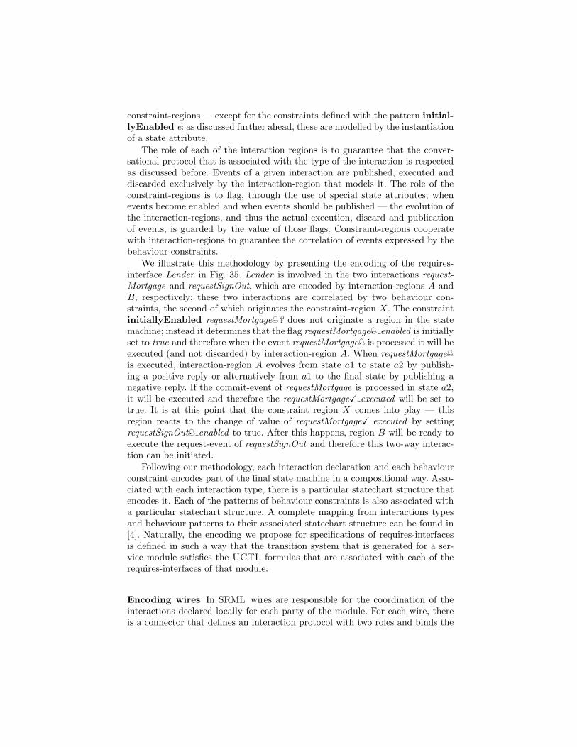
constraint-regions — except for the constraints defined with the pattern initial-lyEnabled e: as discussed further ahead, these are modelled by the instantiationof a state attribute.
The role of each of the interaction regions is to guarantee that the conver-sational protocol that is associated with the type of the interaction is respectedas discussed before. Events of a given interaction are published, executed anddiscarded exclusively by the interaction-region that models it. The role of theconstraint-regions is to flag, through the use of special state attributes, whenevents become enabled and when events should be published — the evolution ofthe interaction-regions, and thus the actual execution, discard and publicationof events, is guarded by the value of those flags. Constraint-regions cooperatewith interaction-regions to guarantee the correlation of events expressed by thebehaviour constraints.
We illustrate this methodology by presenting the encoding of the requires-interface Lender in Fig. 35. Lender is involved in the two interactions request-Mortgage and requestSignOut, which are encoded by interaction-regions A andB, respectively; these two interactions are correlated by two behaviour con-straints, the second of which originates the constraint-region X. The constraintinitiallyEnabled requestMortgage ? does not originate a region in the statemachine; instead it determines that the flag requestMortgage enabled is initiallyset to true and therefore when the event requestMortgage is processed it will beexecuted (and not discarded) by interaction-region A. When requestMortgage
is executed, interaction-region A evolves from state a1 to state a2 by publish-ing a positive reply or alternatively from a1 to the final state by publishing anegative reply. If the commit-event of requestMortgage is processed in state a2,it will be executed and therefore the requestMortgageX executed will be set totrue. It is at this point that the constraint region X comes into play — thisregion reacts to the change of value of requestMortgageX executed by settingrequestSignOut enabled to true. After this happens, region B will be ready toexecute the request-event of requestSignOut and therefore this two-way interac-tion can be initiated.
Following our methodology, each interaction declaration and each behaviourconstraint encodes part of the final state machine in a compositional way. Asso-ciated with each interaction type, there is a particular statechart structure thatencodes it. Each of the patterns of behaviour constraints is also associated witha particular statechart structure. A complete mapping from interactions typesand behaviour patterns to their associated statechart structure can be found in[4]. Naturally, the encoding we propose for specifications of requires-interfacesis defined in such a way that the transition system that is generated for a ser-vice module satisfies the UCTL formulas that are associated with each of therequires-interfaces of that module.
Encoding wires In SRML wires are responsible for the coordination of theinteractions declared locally for each party of the module. For each wire, thereis a connector that defines an interaction protocol with two roles and binds the
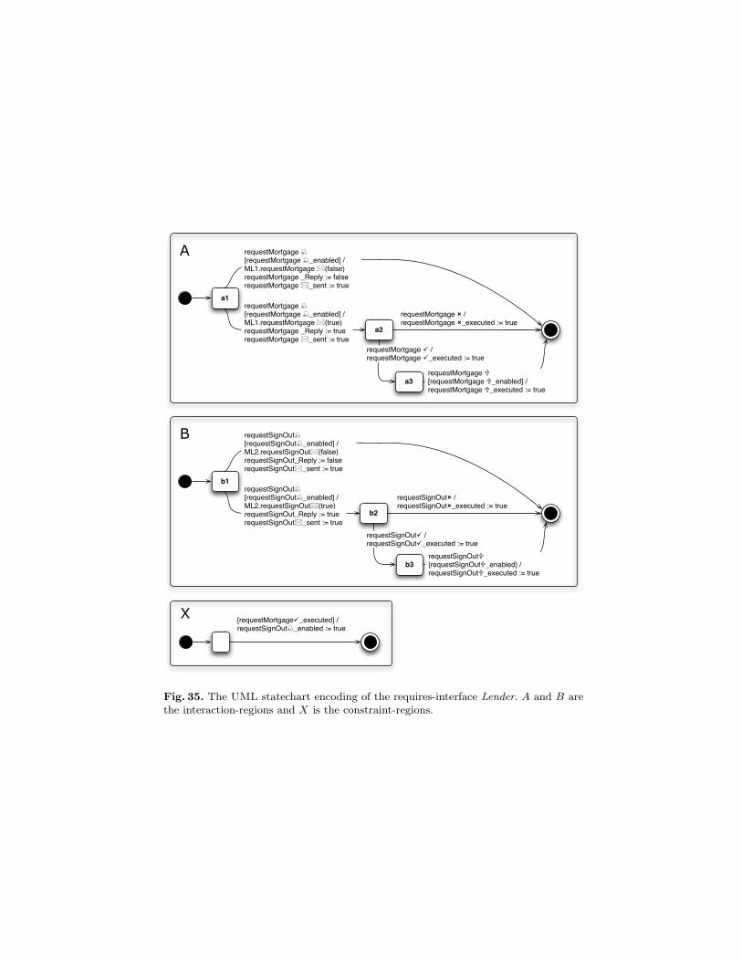
[requestMortgage_executed] /requestSignOut_enabled := true
X
b1
b2
requestSignOut /requestSignOut_executed := true
b3
requestSignOut /requestSignOut_executed := true
B requestSignOut[requestSignOut_enabled] /ML2.requestSignOut(false)requestSignOut_Reply := falserequestSignOut_sent := true
requestSignOut[requestSignOut_enabled] / ML2.requestSignOut(true)requestSignOut_Reply := truerequestSignOut_sent := true
requestSignOut[requestSignOut_enabled] /requestSignOut_executed := true
a1
a2
requestMortgage /requestMortgage _executed := true
a3
requestMortgage /requestMortgage _executed := true
A requestMortgage [requestMortgage _enabled] /ML1.requestMortgage (false)requestMortgage _Reply := falserequestMortgage _sent := true
requestMortgage [requestMortgage _enabled] / ML1.requestMortgage (true)requestMortgage _Reply := truerequestMortgage _sent := true
requestMortgage [requestMortgage _enabled] /requestMortgage _executed := true
Fig. 35. The UML statechart encoding of the requires-interface Lender. A and B arethe interaction-regions and X is the constraint-regions.
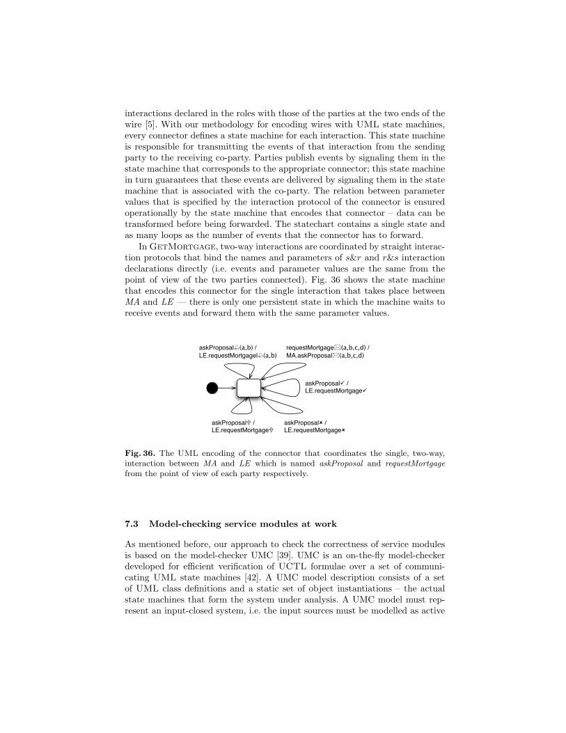
interactions declared in the roles with those of the parties at the two ends of thewire [5]. With our methodology for encoding wires with UML state machines,every connector defines a state machine for each interaction. This state machineis responsible for transmitting the events of that interaction from the sendingparty to the receiving co-party. Parties publish events by signaling them in thestate machine that corresponds to the appropriate connector; this state machinein turn guarantees that these events are delivered by signaling them in the statemachine that is associated with the co-party. The relation between parametervalues that is specified by the interaction protocol of the connector is ensuredoperationally by the state machine that encodes that connector – data can betransformed before being forwarded. The statechart contains a single state andas many loops as the number of events that the connector has to forward.
In GetMortgage, two-way interactions are coordinated by straight interac-tion protocols that bind the names and parameters of s&r and r&s interactiondeclarations directly (i.e. events and parameter values are the same from thepoint of view of the two parties connected). Fig. 36 shows the state machinethat encodes this connector for the single interaction that takes place betweenMA and LE — there is only one persistent state in which the machine waits toreceive events and forward them with the same parameter values.
askProposal(a,b) / LE.requestMortgagel(a,b)
askProposal / LE.requestMortgage
askProposal / LE.requestMortgage
askProposal / LE.requestMortgage
requestMortgage(a,b,c,d) / MA.askProposal(a,b,c,d)
Fig. 36. The UML encoding of the connector that coordinates the single, two-way,interaction between MA and LE which is named askProposal and requestMortgagefrom the point of view of each party respectively.
7.3 Model-checking service modules at work
As mentioned before, our approach to check the correctness of service modulesis based on the model-checker UMC [39]. UMC is an on-the-fly model-checkerdeveloped for efficient verification of UCTL formulae over a set of communi-cating UML state machines [42]. A UMC model description consists of a setof UML class definitions and a static set of object instantiations – the actualstate machines that form the system under analysis. A UMC model must rep-resent an input-closed system, i.e. the input sources must be modelled as active
objects interacting with the rest of the system. Each state machine has a poolthat buffers the set of signals that have been received from other machines untilthey are processed by that machine. According to its class definition, each statemachine has at any given time a value for each of its attributes and a set ofcurrently active sub states as specified by the statechart diagram of the class.
In order to illustrate our model-checking approach we will discuss how tomodel-check the module GetMortgage. First, we have encoded each of itsexternal-required interfaces and each of its connectors using the methodologydescribed in the previous section. Adding the two components that orchestratethe system, we ended up with a set of fourteen communicating UML statemachines. Because every input source of a UMC model must also be modelledvia an active object, we had to define a machine that initiates the interactionsadvertised in the provides-interface Customer, thus modelling a generic clientof the service. Using this system as input to the UMC model-checker, we wereable to verify that the doubly labelled transition system that is generated doessatisfy the properties associated with the provides-interface Customer, shownin Fig. 16. As discussed before, these consists of the properties associated withthe types of the declared interactions and those that derive from the patterns ofbehaviour.
8 Analysing timing properties of complex services
In this Section, we show how SRML can be extended in order to model thedelays involved in the business process through which a service is provided andhow time-related properties of service-oriented models can be analysed over suchmodels. For instance, we have in mind the ability to certify that the mortgage-brokerage service satisfies properties of the form “In at least 80% of the cases, areply to a request for a mortgage proposal will be sent within 7 seconds”. Prop-erties of this kind are extremely important in a number of application domainsand are usually part of the service level agreements (SLAs) that are negotiatedbetween clients and providers. This approach draws from the work reportedin [53].
8.1 Timing issues in SRML models
Given two events e1 and e2, we denote by Delay(e1, e2) the time that sepa-rates their occurrences, e.g. Delay(getProposal , getProposal� ) in the exam-ple above. Because we wish to adopt the PEPA analysis tools [51,19], we assumethat such delays follow an exponential distribution of the form FDelay(e1,e2)(t) =1−e−rt. In practical applications, it is rarely the case that it is possible to obtaina complete response-time distribution of all services in the problem under study.It is far more likely that one will only know the average response time. In thissetting, it is indeed correct to capture the inherent stochasticity in the systemthrough a exponential distribution. The exponential distribution requires only asingle parameter, the average response time. Other distributions would require
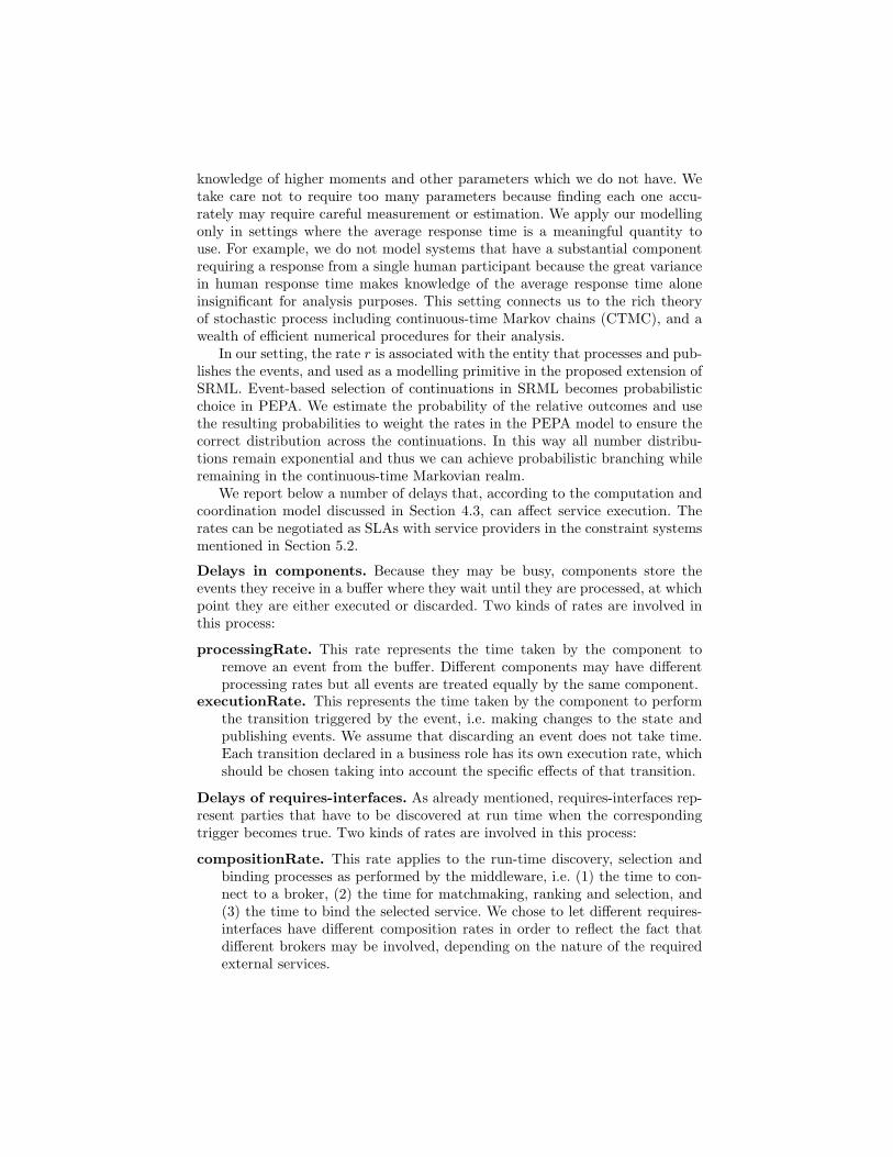
knowledge of higher moments and other parameters which we do not have. Wetake care not to require too many parameters because finding each one accu-rately may require careful measurement or estimation. We apply our modellingonly in settings where the average response time is a meaningful quantity touse. For example, we do not model systems that have a substantial componentrequiring a response from a single human participant because the great variancein human response time makes knowledge of the average response time aloneinsignificant for analysis purposes. This setting connects us to the rich theoryof stochastic process including continuous-time Markov chains (CTMC), and awealth of efficient numerical procedures for their analysis.
In our setting, the rate r is associated with the entity that processes and pub-lishes the events, and used as a modelling primitive in the proposed extension ofSRML. Event-based selection of continuations in SRML becomes probabilisticchoice in PEPA. We estimate the probability of the relative outcomes and usethe resulting probabilities to weight the rates in the PEPA model to ensure thecorrect distribution across the continuations. In this way all number distribu-tions remain exponential and thus we can achieve probabilistic branching whileremaining in the continuous-time Markovian realm.
We report below a number of delays that, according to the computation andcoordination model discussed in Section 4.3, can affect service execution. Therates can be negotiated as SLAs with service providers in the constraint systemsmentioned in Section 5.2.
Delays in components. Because they may be busy, components store theevents they receive in a buffer where they wait until they are processed, at whichpoint they are either executed or discarded. Two kinds of rates are involved inthis process:
processingRate. This rate represents the time taken by the component toremove an event from the buffer. Different components may have differentprocessing rates but all events are treated equally by the same component.
executionRate. This represents the time taken by the component to performthe transition triggered by the event, i.e. making changes to the state andpublishing events. We assume that discarding an event does not take time.Each transition declared in a business role has its own execution rate, whichshould be chosen taking into account the specific effects of that transition.
Delays of requires-interfaces. As already mentioned, requires-interfaces rep-resent parties that have to be discovered at run time when the correspondingtrigger becomes true. Two kinds of rates are involved in this process:
compositionRate. This rate applies to the run-time discovery, selection andbinding processes as performed by the middleware, i.e. (1) the time to con-nect to a broker, (2) the time for matchmaking, ranking and selection, and(3) the time to bind the selected service. We chose to let different requires-interfaces have different composition rates in order to reflect the fact thatdifferent brokers may be involved, depending on the nature of the requiredexternal services.
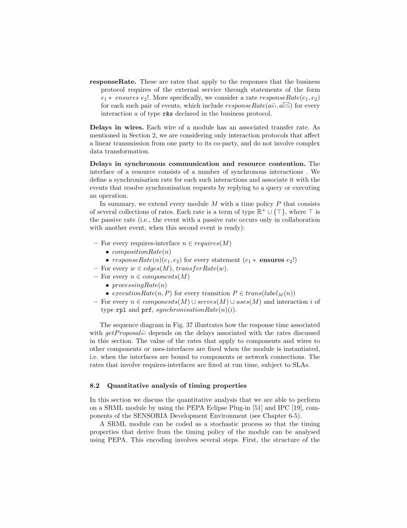
responseRate. These are rates that apply to the responses that the businessprotocol requires of the external service through statements of the forme1 ∗ ensures e2!. More specifically, we consider a rate responseRate(e1, e2)for each such pair of events, which include responseRate(a , a� ) for everyinteraction a of type r&s declared in the business protocol.
Delays in wires. Each wire of a module has an associated transfer rate. Asmentioned in Section 2, we are considering only interaction protocols that affecta linear transmission from one party to its co-party, and do not involve complexdata transformation.
Delays in synchronous communication and resource contention. Theinterface of a resource consists of a number of synchronous interactions . Wedefine a synchronisation rate for each such interactions and associate it with theevents that resolve synchronisation requests by replying to a query or executingan operation.
In summary, we extend every module M with a time policy P that consistsof several collections of rates. Each rate is a term of type R+ ∪ {>}, where > isthe passive rate (i.e., the event with a passive rate occurs only in collaborationwith another event, when this second event is ready):
– For every requires-interface n ∈ requires(M)• compositionRate(n)• responseRate(n)(e1, e2) for every statement (e1 ∗ ensures e2!)
– For every w ∈ edges(M), transferRate(w).– For every n ∈ components(M)• processingRate(n)• executionRate(n, P ) for every transition P ∈ trans(labelM (n))
– For every n ∈ components(M) ∪ serves(M) ∪ uses(M) and interaction i oftype rpl and prf, synchronisationRate(n)(i).
The sequence diagram in Fig. 37 illustrates how the response time associatedwith getProposal depends on the delays associated with the rates discussedin this section. The value of the rates that apply to components and wires toother components or uses-interfaces are fixed when the module is instantiated,i.e. when the interfaces are bound to components or network connections. Therates that involve requires-interfaces are fixed at run time, subject to SLAs.
8.2 Quantitative analysis of timing properties
In this section we discuss the quantitative analysis that we are able to performon a SRML module by using the PEPA Eclipse Plug-in [51] and IPC [19], com-ponents of the SENSORIA Development Environment (see Chapter 6-5).
A SRML module can be coded as a stochastic process so that the timingproperties that derive from the timing policy of the module can be analysedusing PEPA. This encoding involves several steps. First, the structure of the
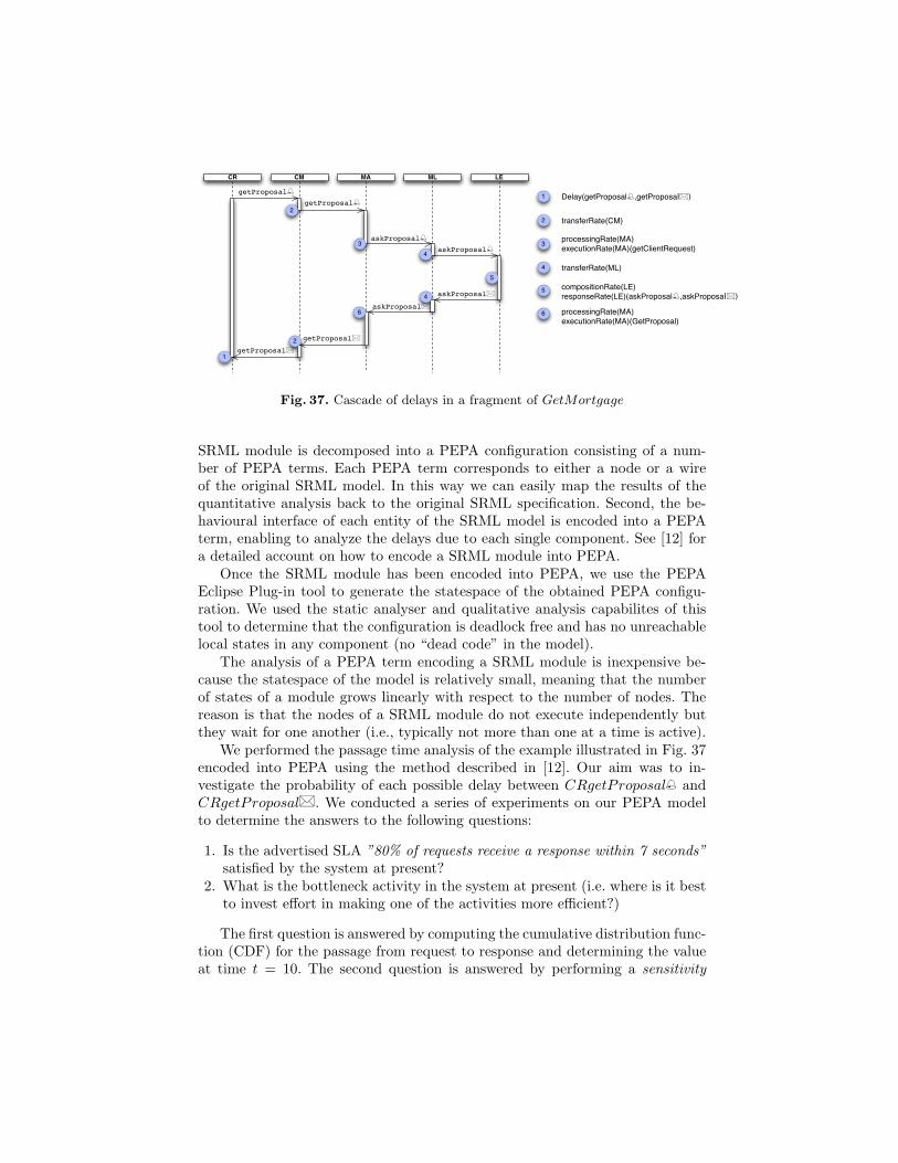
CMCR MA ML LE
getProposal
getProposal
askProposal
askProposal
askProposal
askProposal
getProposal
getProposal
34
5
4
6
Delay(getProposal,getProposal)
transferRate(CM)
processingRate(MA)executionRate(MA)(getClientRequest)
processingRate(MA)executionRate(MA)(GetProposal)
transferRate(ML)
compositionRate(LE)responseRate(LE)(askProposal,askProposal)
1
2
2
1
2
3
4
5
6
Fig. 37. Cascade of delays in a fragment of GetMortgage
SRML module is decomposed into a PEPA configuration consisting of a num-ber of PEPA terms. Each PEPA term corresponds to either a node or a wireof the original SRML model. In this way we can easily map the results of thequantitative analysis back to the original SRML specification. Second, the be-havioural interface of each entity of the SRML model is encoded into a PEPAterm, enabling to analyze the delays due to each single component. See [12] fora detailed account on how to encode a SRML module into PEPA.
Once the SRML module has been encoded into PEPA, we use the PEPAEclipse Plug-in tool to generate the statespace of the obtained PEPA configu-ration. We used the static analyser and qualitative analysis capabilites of thistool to determine that the configuration is deadlock free and has no unreachablelocal states in any component (no “dead code” in the model).
The analysis of a PEPA term encoding a SRML module is inexpensive be-cause the statespace of the model is relatively small, meaning that the numberof states of a module grows linearly with respect to the number of nodes. Thereason is that the nodes of a SRML module do not execute independently butthey wait for one another (i.e., typically not more than one at a time is active).
We performed the passage time analysis of the example illustrated in Fig. 37encoded into PEPA using the method described in [12]. Our aim was to in-vestigate the probability of each possible delay between CRgetProposal andCRgetProposal� . We conducted a series of experiments on our PEPA modelto determine the answers to the following questions:
1. Is the advertised SLA ”80% of requests receive a response within 7 seconds”satisfied by the system at present?
2. What is the bottleneck activity in the system at present (i.e. where is it bestto invest effort in making one of the activities more efficient?)
The first question is answered by computing the cumulative distribution func-tion (CDF) for the passage from request to response and determining the valueat time t = 10. The second question is answered by performing a sensitivity
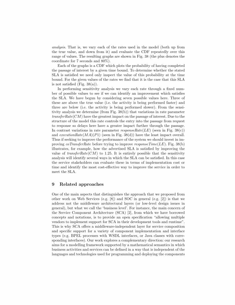
analysis. That is, we vary each of the rates used in the model (both up fromthe true value, and down from it) and evaluate the CDF repeatedly over thisrange of values. The resulting graphs are shown in Fig. 38 (the plus denotes thecoordinate for 7 seconds and 80%).
Each of the graphs is a CDF which plots the probability of having completedthe passage of interest by a given time bound. To determine whether the statedSLA is satisfied we need only inspect the value of this probability at the timebound. For the given values of the rates we find that it is the case that this SLAis not satisfied (Fig. 38(a)).
In performing sensitivity analysis we vary each rate through a fixed num-ber of possible values to see if we can identify an improvement which satisfiesthe SLA. We have begun by considering seven possible values here. Three ofthese are above the true value (i.e. the activity is being performed faster) andthree are below (i.e. the activity is being performed slower). From the sensi-tivity analysis we determine (from Fig. 38(b)) that variations in rate parametertransferRate(CM) have the greatest impact on the passage of interest. Due to thestructure of the model this rate controls the entry into the passage from requestto response so delays here have a greater impact further through the passage.In contrast variations in rate parameter responseRate(LE) (seen in Fig. 38(c))and executionRate(MA)(P1) (seen in Fig. 38(d)) have the least impact overall.Thus if seeking to improve the performance of the system we should invest in im-proving coTransferRate before trying to improve responseTime(LE). Fig. 38(b)illustrates, for example, how the advertised SLA is satisfied by improving thevalue of transferRate(CM) to 1.25. It is entirely possible that the sensitivityanalysis will identify several ways in which the SLA can be satisfied. In this casethe service stakeholders can evaluate these in terms of implementation cost ortime and identify the most cost-effective way to improve the service in order tomeet the SLA.
9 Related approaches
One of the main aspects that distinguishes the approach that we proposed fromother work on Web Services (e.g. [8]) and SOC in general (e.g. [2]) is that weaddress not the middleware architectural layers (or low-level design issues ingeneral), but what we call the ‘business level’. For instance, the main concern ofthe Service Component Architecture (SCA) [2], from which we have borrowedconcepts and notations, is to provide an open specification “allowing multiplevendors to implement support for SCA in their development tools and runtime”.This is why SCA offers a middleware-independent layer for service compositionand specific support for a variety of component implementation and interfacetypes (e.g. BPEL processes with WSDL interfaces, or Java classes with corre-sponding interfaces). Our work explores a complementary direction: our researchaims for a modelling framework supported by a mathematical semantics in whichbusiness activities and services can be defined in a way that is independent of thelanguages and technologies used for programming and deploying the components
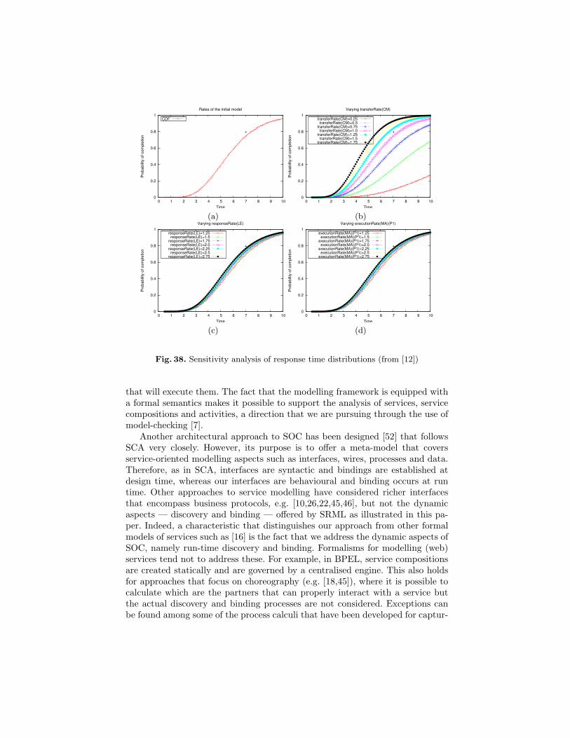
0
0.2
0.4
0.6
0.8
1
0 1 2 3 4 5 6 7 8 9 10
Pro
ba
bili
ty o
f co
mp
letio
n
Time
Rates of the initial model
+
CDF
0
0.2
0.4
0.6
0.8
1
0 1 2 3 4 5 6 7 8 9 10
Pro
ba
bili
ty o
f co
mp
letio
n
Time
Varying transferRate(CM)
+
transferRate(CM)=0.25transferRate(CM)=0.5
transferRate(CM)=0.75transferRate(CM)=1.0
transferRate(CM)=1.25transferRate(CM)=1.5
transferRate(CM)=1.75
(a) (b)
0
0.2
0.4
0.6
0.8
1
0 1 2 3 4 5 6 7 8 9 10
Pro
ba
bili
ty o
f co
mp
letio
n
Time
Varying responseRate(LE)
+
responseRate(LE)=1.25responseRate(LE)=1.5
responseRate(LE)=1.75responseRate(LE)=2.0
responseRate(LE)=2.25responseRate(LE)=2.5
responseRate(LE)=2.75
0
0.2
0.4
0.6
0.8
1
0 1 2 3 4 5 6 7 8 9 10
Pro
ba
bili
ty o
f co
mp
letio
n
Time
Varying executionRate(MA)(P1)
+
executionRate(MA)(P1)=1.25executionRate(MA)(P1)=1.5
executionRate(MA)(P1)=1.75executionRate(MA)(P1)=2.0
executionRate(MA)(P1)=2.25executionRate(MA)(P1)=2.5
executionRate(MA)(P1)=2.75
(c) (d)
Fig. 38. Sensitivity analysis of response time distributions (from [12])
that will execute them. The fact that the modelling framework is equipped witha formal semantics makes it possible to support the analysis of services, servicecompositions and activities, a direction that we are pursuing through the use ofmodel-checking [7].
Another architectural approach to SOC has been designed [52] that followsSCA very closely. However, its purpose is to offer a meta-model that coversservice-oriented modelling aspects such as interfaces, wires, processes and data.Therefore, as in SCA, interfaces are syntactic and bindings are established atdesign time, whereas our interfaces are behavioural and binding occurs at runtime. Other approaches to service modelling have considered richer interfacesthat encompass business protocols, e.g. [10,26,22,45,46], but not the dynamicaspects — discovery and binding — offered by SRML as illustrated in this pa-per. Indeed, a characteristic that distinguishes our approach from other formalmodels of services such as [16] is the fact that we address the dynamic aspects ofSOC, namely run-time discovery and binding. Formalisms for modelling (web)services tend not to address these. For example, in BPEL, service compositionsare created statically and are governed by a centralised engine. This also holdsfor approaches that focus on choreography (e.g. [18,45]), where it is possible tocalculate which are the partners that can properly interact with a service butthe actual discovery and binding processes are not considered. Exceptions canbe found among some of the process calculi that have been developed for captur-
ing semantic foundations of SOC (e.g. [28,17,37]). However, such process calculitend not to address dynamic reconfiguration separately from computation, i.e.the process of discovery and binding is handled as part of the computation per-formed by a service. As far as we know, SRML is the first service-modellinglanguage to separate these two concerns.
Indeed, in our opinion, what makes SOC different from other paradigms isthe fact that it concerns run-time, not design-time complexity. This is also theview exposed in [23] — a very clear account of what distinguishes SOC fromCBD (Component Based Development). Whereas in CBD component selectionis either performed at design time or programmed over a fixed universe of com-ponents, SOC provides a means of obtaining functionalities by orchestrating in-teractions among components that are procured at run time according to given(functional) types and service level constraints.
Another area related to the work that we have presented concerns the non-functional aspects of services, namely the policies and constraints for servicelevel agreement that have to be taken into account in the composition of ser-vices. Most of the research developed in this area has been devoted to languagesfor modelling specific kinds of policies (over specific non-functional features) andof selection algorithms, e.g. SCA Policy [2] among several others [40,41,49,48,27].These languages have been primarily designed to be part of the technology avail-able for implementing and executing services. As such, they are tailored to thetechnological infrastructure that is currently enabling web services and are notbest placed for being used at high-levels of business modelling.
10 Concluding remarks
In this chapter, we presented an overview of the formal approach for mod-elling service-oriented application that we developed within Sensoriatowards amethodological and mathematical characterisation of the service-oriented com-puting paradigm [3]. The approach is built around a prototype language calledSRML — the Sensoria Modelling Reference Language — and offers an en-gineering environment that includes abstraction mappings from workflow lan-guages (such as BPEL [14]) and policy languages (such as StPowla [13]), model-checking techniques that support qualitative analysis, and stochastic analysistechniques for timing properties. SRML is supported by an Eclipse-based editor(available from www.cs.le.ac.uk/srml) that is part of the Sensoria DevelopmentEnvironment (SDE). A mathematical semantics is available for all aspects of theapproach as partially illustrated in the paper (see [4,6,29,32,30,33] for a morecomprehensive account).
This methodology has been tested in a number of other domains, includingtelco [7], travel [6], automotive [15] and procurement [31] scenarios. Tutorialshave been given at CONCUR’08, SEFM’08, SFM’09 and DISCOTEC’09. Moreextended tutorials were given at the Technical University of Valencia (Spain) andthe Summer School on Web Engineering held in 2007 in La Plata, Argentina.
SRML is also being taught at the University of Leicester to postgraduate stu-dents in Computer Science.
Acknowledgments
We would like to thank our colleagues in the Sensoria project for many usefuldiscussions on the topics covered in this paper. Stefania Gnesi and Franco Maz-zanti (CNR-ISTI) contributed directly to the work presented in Section 7, andStephen Gilmore (Edinburgh), Monika Solanki (Leicester) and Vishnu Vankay-ala (Leicester) to Section 8. Artur Boronat and Yi Hong (Leicester) contributeddirectly to the development of the SRML Editor. We are also indebted to ColinGilmore from Box Tree Mortgage Solutions (Leicester) for taking us through themortgage-brockerage case study.
References
1. Global computing initiative. http://cordis.europa.eu/ist/fet/gc.htm.2. The open service oriented architecture collaboration. Whitepapers and specifica-
tions available from www.osoa.org (see also oasis-opencsa.org/sca).3. Sensoria consortium, 2007. White paper available from http://www.sensoria-
ist.eu/files/whitePaper.pdf.4. J. Abreu. Modelling Business Conversations in Service Component Architectures.
PhD thesis, University of Leicester, 2009.5. J. Abreu, L. Bocchi, J. L. Fiadeiro, and A. Lopes. Specifying and composing inter-
action protocols for service-oriented system modelling. In J. Derrick and J. Vain,editors, Formal Methods for Networked and Distributed Systems, FORTE’07, vol-ume 4574 of LNCS, pages 358–373, 2007.
6. J. Abreu and J. Fiadeiro. A coordination model for service-oriented interactions.In D. Lea and G. Zavattaro, editors, Coordination Languages and Models, volume5052 of LNCS, pages 1–16, 2008.
7. J. Abreu, F. Mazzanti, J. Fiadeiro, and S. Gnesi. A model-checking approach forservice component architectures. In D. Lee, A. Lopes, and A. Poetzsch-Heffter, ed-itors, Formal Techniques for Distributed Systems, FMOODS/FORTE ’09, volume5522 of LNCS, pages 212–217, 2009.
8. G. Alonso, F. Casati, H. Kuno, and V. Machiraju. Web Services. Springer, 2004.9. M. Beek, A. Fantechi, S. Gnesi, and F. Mazzanti. An action/state-based model-
checking approach for the analysis of communication protocols for Service-OrientedApplications. In FMICS’07, LNCS. Springer-Verlag, Berlin, 2007.
10. B. Benatallah, F. Casati, and F. Toumani. Web services conversation modeling:A cornerstone for e-business automation. IEEE Internet Computing, 8(1):46–54,2004.
11. S. Bistarelli, U. Montanari, and F. Rossi. Semiring-based constraint satisfactionand optimization. Journal of the ACM, 44(2):201–236, 1997.
12. L. Bocchi, J. Fiadeiro, S. Gilmore, J. Abreu, M. Solanki, and V. Vankay-ala. Analysing time-related properties of service-oriented systems, 2010.Submitted. Available from http://www.cs.le.ac.uk/people/jfiadeiro/Papers/
SRML-T.pdf.

13. L. Bocchi, S. Gorton, and S. Reiff-Marganiec. Engineering service-oriented appli-cations: From stpowla processes to srml models. In J. Fiadeiro and P. Inverardi,editors, Fundamental Aspects of Software Engineering, volume 4961 of LNCS, pages163–178, 2008.
14. L. Bocchi, Y. Hong, A. Lopes, and J. Fiadeiro. From bpel to srml: a formaltransformational approach. In M. Dumas and R. Heckel, editors, Web Servicesand Formal Methods, volume 4937 of LNCS, pages 92–107, 2007.
15. L. Bocchi, J. L.Fiadeiro, and A. Lopes. Service-oriented modelling of automotivesystems. In COMPSAC, pages 1059–1064. IEEE Computer Society, 2008.
16. M. Broy, I. Kruger, and M. Meisinger. A formal model of services. ACM TOSEM,16(1):1–40, 2007.
17. M. Buscemi and U. Montanari. Cc-pi: A constraint-based language for specifyingservice level agreements. In R. De Nicola, editor, ESOP 2007, volume 4421 ofLNCS, pages 18–32, 2007.
18. M. Carbone, K. Honda, and N. Yoshida. Structured communication-centred pro-gramming for web services. In R. De Nicola, editor, ESOP 2007, volume 4421 ofLNCS, pages 2–17, 2007.
19. A. Clark. The ipclib PEPA Library. In Mor Harchol-Balter, Marta Kwiatkowska,and Miklos Telek, editors, Proceedings of the 4th International Conference on theQuantitative Evaluation of SysTems (QEST), pages 55–56. IEEE, September 2007.
20. R. De Nicola and F. W. Vaandrager. Action versus state based logics for transitionsystems. In Semantics of Systems of Concurrent Processes, pages 407–419, 1990.
21. Rocco De Nicola and Frits W. Vaandrager. Three logics for branching bisimulation.J. ACM, 42(2):458–487, 1995.
22. R. M. Dijkman and M. Dumas. Service-oriented design: a multi-viewpoint ap-proach. International Journal of Cooperative Information Systems, 13(4):337–368,2004.
23. A. Elfatatry. Dealing with change: components versus services. Communicationsof the ACM, 50(8):35–39, 2007.
24. E.M. Clarke, E.A. Emerson and A.P. Sistla. Automatic Verification of Finite StateConcurrent Systems using Temporal Logic Specifications. ACM Transactions onProgramming Languages and Systems, 8(2):244–263, 1986.
25. G. Coulson et al. A generic component model for building systems software. ACMTOCS, 26(1):1–42, 2008.
26. L. Bordeaux et al. When are two web services compatible? In Technologies forE-Services, volume 3324 of LNCS, pages 15–28, 2005.
27. L. Zeng et al. Qos-aware middleware for web services composition. IEEE Trans-actions on Software Engineering, 30(5):311–327, 2004.
28. M. Boreale et al. Scc: a service centered calculus. In M. Bravetti, M. Nunez, andG. Zavattaro, editors, Web Services and Formal Methods, volume 4184 of LNCS,pages 38–57, 2006.
29. J. L. Fiadeiro, A. Lopes, and J. Abreu. A formal model for service-oriented inter-actions, 2010. Available from www.cs.le.ac.uk/srml.
30. J. L. Fiadeiro, A. Lopes, and L. Bocchi. An abstract semantics of service discoveryand binding. Formal Aspects of Computing. To appear.
31. J. L. Fiadeiro, A. Lopes, and L. Bocchi. A formal approach to service-orientedarchitecture. In M. Nunez M. Bravetti and G. Zavattaro, editors, Web Servicesand Formal Methods, volume 4184 of LNCS, pages 193–213, 2006.
32. J. L. Fiadeiro, A. Lopes, and L. Bocchi. Algebraic semantics of service componentmodules. In J. L. Fiadeiro and P. Y. Schobbens, editors, Algebraic DevelopmentTechniques, volume 4409 of LNCS, pages 37–55, 2007.

33. J. L. Fiadeiro and V. Schmitt. Structured co-spans: an algebra of interactionprotocols. In T. Mossakowski, U. Montanari, and M. Haveraaen, editors, Algebraand Coalgebra in Computer Science, volume 4624 of LNCS, pages 194–209, 2007.
34. I. Foster and C. Kesselman, editors. The Grid 2: Blueprint for a New ComputingInfrastructure. Morgan Kaufmann, 2004.
35. Q. Gu and P. Lago. A stakeholder-driven service life-cycle model for soa. InIW-SOSWE’07, pages 1–7, 2007.
36. J. Hillston. A Compositional Approach to Performance Modelling. 1996.37. A. Lapadula, R. Pugliese, and F. Tiezzi. A calculus for orchestration of web
services. volume 4421 of LNCS, pages 33–47, 2007.38. P. Mayer, N. Koch, and A. Schroder. A model-driven approach to service orches-
tration. In Proceedings of IEEE International Conference on Services Computing(SCC 2008), 2008.
39. F. Mazzanti. UMC User Guide v3.3. Technical Report 2006-TR-33, Istitutodi Scienza e Tecnologie dell’Informazione “A. Faedo”, CNR. Available fromhttp://fmt.isti.cnr.it/WEBPAPER/UMC-UG33.pdf, 2006.
40. N. Mukhi, P. Plebani, I. Silva-Lepe, and T. Mikalsen. Supporting policy-drivenbehaviours in web services: experiences and issues. In Proceedings ICSOC’04, pages322–328, 2004.
41. A. Mukhija, A. Dingwall-Smith, and D. Rosenblum. Qos-aware service compositionin dino. In ECOWS 2007, pages 3–12. ACM Press, 2007.
42. Object Management Group. Unified Modeling Language. http://www.uml.org/.43. C. Peltz. Web services orchestration and choreography. IEEE Computer,
36(10):46–52, 2003.44. J. Rao and X. Su. A survey of automated web service composition methods.
In J. Cardoso and A. Sheth, editors, Semantic Web Services and Web ProcessComposition, volume 3387 of LNCS, pages 43–54, 2004.
45. W. Reisig. Modeling and analysis techniques for web services and business pro-cesses. In FMOODS 2005, volume 3535 of LNCS, pages 243–258, 2005.
46. W. Reisig. Towards a theory of services. In UNISCON 2008, pages 271–281, 2008.47. M. Shaw and D. Garlan. Software Architecture: Perspectives on an Emerging
Discipline. 1996.48. K-J. Lin T. Yu. A broker-based framework for qos-aware web service composition.
In Proc. of the Intl. Conf. on e-Technology, e-Commerce and e-Service, pages 22–29. IEEE Computer Society, 2005.
49. OASIS WSBPEL TC. Web services business process execution language, 2007.Version 2.0. Technical report, OASIS.
50. M. ter Beek, A. Fantechi, S. Gnesi, and F. Mazzanti. An action/state-based modelchecking approach for the analysis of communication protocols for service-orientedapplications. In S. Leue and P. Merino, editors, Formal Methods for IndustrialCritical Systems, volume 4916 of LNCS, pages 133–148.
51. M. Tribastone. The PEPA Plug-in Project. In Quantitative Evaluation of SysTems,pages 53–54. IEEE, 2007.
52. W. van der Aalst, M. Beisiegel, K. van Hee, and D. Konig. An soa-based ar-chitecture framework. Journal of Business Process Integration and Management,2(2):91–101, 2007.
53. V. Vankayala. Business process modelling using SRML (Advanced System Design- Project Dissertation), 2008.
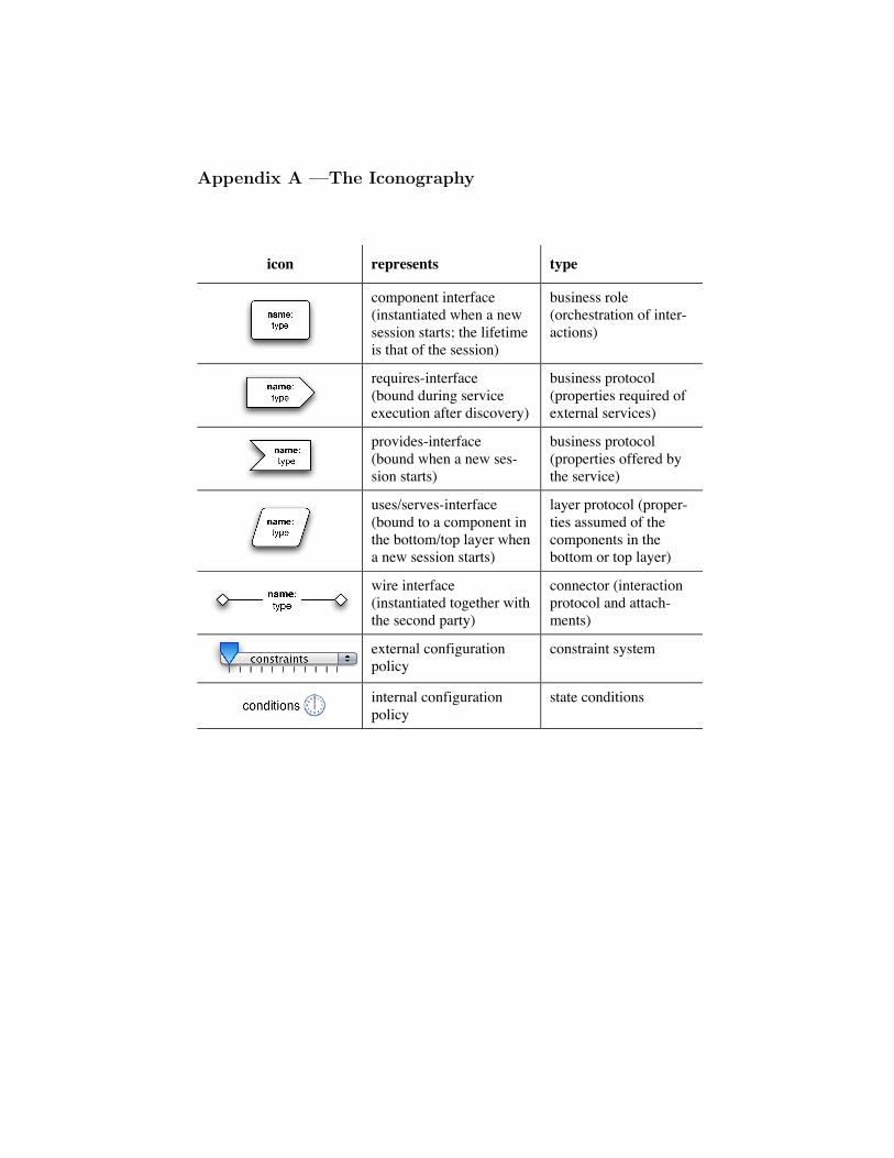
Appendix A —The Iconography
– 46 –
Appendix A – The Iconography
icon represents type sections
component interface (instantiated when a new session starts; the lifetime is that of the session)
business role (orchestration of inter-actions)
requires-interface (bound during service execution after discovery)
business protocol (properties required of external services)
provides-interface (bound when a new ses-sion starts)
business protocol (properties offered by the service)
uses/serves-interface (bound to a component in the bottom/top layer when a new session starts)
layer protocol (proper-ties assumed of the components in the bottom or top layer)
wire interface (instantiated together with the second party)
connector (interaction protocol and attach-ments)
external configuration policy
constraint system
internal configuration policy
state conditions
Related Documents