FAZEL mf 1 f ( * The Sensitive Quadrant Electrometer ' it Physics ,.:^-:;:Wv:^;::;:^^^ "v. * A.M. -. im^^g: 19 15 S - xrmv. fyv Iv ''I'iv vl^V • -y^'''"' jl/JjT.n-O'IS . ' (.lA.R^r i /,!';.'!, ;,,",'.'\''''.v, L

Welcome message from author
This document is posted to help you gain knowledge. Please leave a comment to let me know what you think about it! Share it to your friends and learn new things together.
Transcript

FAZEL mf1
f(
*
The Sensitive Quadrant Electrometer '
it
Physics ,.:^-:;:Wv:^;::;:^^^
"v.
*
A.M. -. im^^g:
19 15
S -
xrmv. fyv Iv ''I'iv vl^V• -y^'''"'
jl/JjT.n-O'IS .
'
(.lA.R^r i i
/,!';.'!, ;,,",'.'\''''.v, L

THE UNIVERSITY
OF ILLINOIS
LIBRARY


Digitized by the Internet Archive
in 2013
http://archive.org/details/sensitivequadranOOfaze
THE SENSITIVE QUADRANT ELECTROMETER
BY
CHARLES STEVER FAZEL
A. B. Fairmount College, 1914
THESIS
Submitted in Partial Fulfillment of the Requirements for the
Degree of
MASTER OF ARTS
IN PHYSICS
IN
THE GRADUATE SCHOOL
OF THE
UNIVERSITY OF ILLINOIS
1915


UNIVERSITY OF ILLINOIS
THE GRADUATE SCHOOL
May 3 J 1905
1 HEREBY RECOMMEND THAT THE THESIS PREPARED UNDER MY SUPERVISION BY
CHARLES STEVER FAZEL
ENTITLED THE SENSITIVE QUADRANT. ELECTROLiETER
BE ACCEPTED AS FULFILLING THIS PART OF THE REQUIREMENTS FOR THE
DEGREE OF MASTER OF ARTS
XT?'._____ ^.V
Recommendation concurred in:
Committee
on
Final Examination
In Charge of Major Work
Head of Department

UlUC
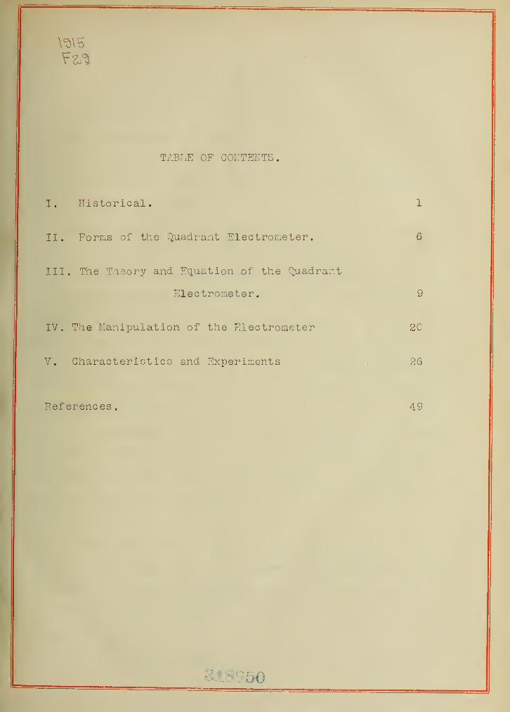
TABLE OF CONTENTS.
I. Historical. 1
II. Forras of the ^'^uadr-ant Electrometer. 6
III. The Theorir and Equation of the Q,uadrant
Electrometer. 9
IV. The Manipulation of the Electrometer 20
V. GharacteriGtics and Experiments , 26
References. 49
50


1.
I. Historical.
In February of trie year 1857 Lord Kelvin published in the
Accademia Pontificia dei imovi Lincei a description of his
quadrant electrometer. This was the first announcEont of the
invention of the instrument which was to become invaluable in
many branches of research.
Essentially, the electrometer as Lord Kelvin invented it
consisted of a short cylinder mounted upon suitable insulation
and cut into four quadrants. Within these quadrants was hung
a light needle which was "dumib-bell shaped". The radially
opposite quadrants were connected and raised to the potential
v/hich it was desired to measure while the other pair were
either grounded or attached to the other terminal of the source
of potential difference. The needle was charged to a potential
different from that of the quadrants by means of some other
source of potential, in what is called the hetrostatic method.
The needle potential which was used in the origional Kelvin
instrument -.vas very high, at times amounting to thousands of
volts, in fact very much higher than that used in the later
forms
.
On the other hand it was found possible to use the electro-
meter by connecting one of the quadrants and the needle to one
terminal of a potential difference and the other quadrant to
the other terminal. This method was called the ideostatic
method
,
While the Kelvin form described above may sound quite

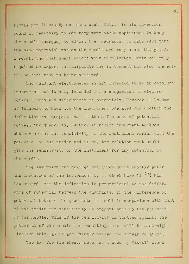
simple yet It ;vas by ne means such. Kelvin in his invention
found it necessary to add very many other appliances to keep
the needle charged, to adjust the quadrants, to mal^e sure that
the same potential was on the needle and many other things. As
a result the instrument became very complicated. This not only
required an expert to manipulate the instrument but also prevent-
ed the best results being attained.
The iuadrant electromieter is not intended to be an absolute
instrument but is only intended for a comparison of electro-
motive forces and differences of potentials. However it became
of interest to know how the instrument operated and v/hether the
deflection was proportional to the difference of potential
between the quadrants. Further it became imiportant to know
v/hether or not the sensitivity of the instrument varied with the
potential of the needle and if so, the relation that would
give the sensitivity of the instrumiont for any potential of
the needle.
The law which was desired was given quite shortly after
the invention of the instrument by J. Clerk I:axv/ell ^'^l His
law stated that the deflection is proportional to the differ-
ence of potential between the quadrants. If the difference of
potential between the quadrants is smxall in comparison with that
of the needle the sensitivity is proportional to the potential
of the needle. Thus if the sensitivity is plotted against the
potential of the needle the resulting curve will be a straight
line and this law is accordingly called the linear relation.
The la.v for the electrometer as stated by Maxwell stood

without question for a nunber of years. This v/as due no doubt,
both to the prestige of the man and the fact that instrui:;ents
had as yet not been developed to that grade of sensitivity
which would make it possible to detect the variation from the
law of Maxwell.
However in 1885, Dr. John Hopkinson published a paper
in which he showed that in his instruiiiont the law was not obeyed.
This, he attributed to tne fact that as he used bifilar suspen-
sions t ie apparent force of gravity v/ould be decreased ofc in-
creased in case the needle was not in tie exact vertical center
of tne quadraiits . This W8.s quite likely tne case in his instru-
ment, yet the same falling off from the line;;-r relation is
found in the single fiber suspensions in use today. This only
goes to show that the apparent change of gravity did not
entirely account for the deviation from the law of Maxwell,
(4)In 1891 Ivlessers Aryton, Perry, and Sumpner published
a paper cbn the same question in which they showed that they
could get tneir instruments to follow any one of three laws.
First the law of I^axv/ell, second the law which Hopkinson found
and finally they could adjust their instrument so that the
sensitivity would not increase or decrease with a change in
tie needle potential. They were inclined to attribute tie
fact of the three laws to the same cause as E.opkinson as they
used the same kind of instrument. They improved tne instrument
somiev/hat by the introduction of certain devices which were
designed to make it follow tne Ilaxwell law. The result was a
further complication in the design of tne instrument.


There was no furt ler advance of note until the invention
(5)of the form of Er. Dolezalek. His form is not ling more than
a return to the origional idea of Lord rlelvin. He reasoned that
witri a conducting suspension he could easily keep t le needle at
the desired potential without the use of the Leyden jar and all
the accompanying appliances. Further he was able to get rid of
the turning friction of the wire in the sulfuric acid which had
been used for ciarging the needle in the Kelvin form. The susp-
ension used was eitaer phosphor bronze or -luartz made conducting.
In addition he decreased the size of the quadrants and made the
needle much lighter by constructing it of silver-ed paper.
This was a great advance for it at the same time made the
instrument much more sensitive and far easier to work with t lan
any previous form and also decreased the electrostatic capacity.
The Dolezalek form is the one in use exclusively at the present
time. This form caused tae old .question of the lav/ of the inst-
rument to rise up with renewed vigor. In order to answer this
question Mr. G. ??, Walker published in 19C3 his paper on that
question which has in a certain sense completed the discussion
of the instrument from a mathematical standpoint, JIuch h'.)wever
is to be learned as to the physical interpretation of the laws
( 7
)
In 191G .r, R. Seattle developed the "control idea" for
the explanation of tae action of the quadrant electrometer. This
forms quite an interesting basis for the discussion of other
forms of electrometers and also for a comparison of t-ieir action
with that of t;ie quadrant.
One of t;ie most important and yet neglected features of
the quadrant electrometer is the variation of the capacity with


5.
with the deflection. This was noticed by Sir J. J, Thomson
in 1898 and he derived an expression whereby he could remove it
from consideration in the problem on which he was working. It
is not at the present time completely solved but it is known
quite well that such a variation exists. The reason for lack
of knowledge along tiis line lies in tne fact taat tliere is no
method sufiiciently sensitive for the measurement of tiie capacity.

6.
II. Forms of t-ie Quadrant Electrometer.
The first modification of the quadrant electrometer "/as
made by Lord Kelvin when he invented the Multicellular Volt-
meter. This instrument is built on the principle of the ideo-
static elec tromxeter . It has the advantage that there is no
current flowing and thus can be used in places where it is
impossible to use either an electromagnetic or hot wire instru-
ment. For example this form is used in the determination of
the potential necessary to cause a spark to pass thru a spark
gap. In addition as the deflection is proportional to the
square of the difference of potential it can be used in the
measurement of alternating current voltages.
Another quite r:-;:portant m^odif ication has been made which
surpassed the original Kelvin form in sensitivity. This is
the formi in which the quadrants are cylindrical and the needle
instead of lying in the horizontal plane lies in the vertical.
( 9
)
The first of this form -was made by Edelmann in 1879. There
are three types of this formi all having in coimuon the cylindric-
al shaped quadrants. The type instruments are those of Boys,
Paschen and Kleiner. Each of these forms have a different kind
of needle.
The instrument exhibited by Boys ^-^^^ in 1891 consisted of
two strips- of dissimilar metals bent in a U shape and fastened
together at the bottom of the U. From this point they were sus-
pended by means of a quartz fiber. In this manner it was possible
to remove the difficulty of charging the needle when a quartz
suspension was used, as the contact of the dissimilar metals


7.
furnished the source of potential. Prof. Boys used as his quad-
rants a test tube lined with four strips of tinfoil.
The instrument of Pas chen^ ^ differs from the above in
the shape of the needle, Ke used simply a flat sheet of light
copper foil in a vertical plane. This was suspended by means of
a platinum wire. The quadrants were of cylindrical shape and
were mounted on amber being com.posed of much heavier material
than Boys used,
(12)The other form is that of Kleiner in which the needle
is a single U shaped strip of metal foil. However the strip is
quite wide and is bent in a cylindrical form so that the top
view of it resembles the needle of the quadrant form of Ivelvin.
flere tne suspension is of platinum and the quadrants are made of
metal mounted on amber. In tnis form there is introduced, in
order to make the field m^ore symmietrical andther set of quadrants
on the interior of those already spoken of. Between the two
sets of quadrants is placed the needle. This formi of instrument
has reached the highest recorded sensitivity of any electrometer.
-6The value of the sensitivity reached was 10 volts per mm,
deflection at a distance of one mieter from the instrument. It
posseses the additional advantage of having a very small capacity,
a very desirable thing in a sensitive elec tromieter . T'his capacity
is about 15 cm. or one half that of the other quadrant types.
Another type of the electrometer with a high sensitivity(13:
IS that made by Hoffmann. This is in reality of the Hankel
form, consisting of a cylindrical metal box similar to that
used in the Kelvin form but cut into t./o parts. Within this bcbx
along the bisecting line is hutig the needle which is in this

case a very small blade in liie shape of the letter L. This mst-
ru.:.ent has the advantage of having the small capacity of 4.8 cm.
The inventor furt;ier claims that he has been able to obtain a
- 4sensitivity of IC volts per mm, and from his data he could
have gone farther but there v;as nothing to be gained in so doing
in the pa.rtiGular problem on- .vhich he was working.
( 14
)
Blondlot and Curie invented another sensitive form
of electrometer which is called the binant. In this form the
box is the same as that described in the Hoffman formi but the
needle consists of a circular disk cut in two equal parts which
are insulated from each other and charged to equal and opposite
potentials from a battery. The bisecting line of the needle is
at right angles to the bisecting line of the cylind'rical box
for the zero position. This' form, is quite sensitive (10 x 5)
but has the great disadvantage of a relatively large capacity.
In this formi the capacity is about tv/ice tiiat of the largest
quadrant form. It might be possible in this instrument to reduce
the dimensions to about those of the Kleiner electrometer and
thus make its capacity much smaller than it is in the present
form.
These constitute the most promising forms of tlie electro-
meter today. The object in view in all of these is to reduce the
capacity to a miinimium and at the same tim^e increase the sensitiv-
ity as much as possible. The secondary object is to increase the
ease and rapidity of manipulation. However it seems that with an
increase in the sensitivity the difficulties of m^anipulat ion
must inevitably increase.


9.
III. Tlie Theory and Equation of the '.^^uadrant Eleotrometer
.
As mentioned previously the first theory and equation for
the quadrant electrometer v/as given by J. Clerk Maxwell. This
is not only of historic interest but also has furnished the
basis of all of the later 7/ork that has been done alon£ this
line. The Maxwell equation is used in all of the more elementary
texts today, due to its simplicity and to the fact tnat it holds
for very large ranges of potential.
The method of discussiori used by Maxwell was as follows.
Ye designate the potential of the two quadrants as A and B, that
of the needle as G, and let a, b, and c, be the respective
capacities. Further we suppose that the needle is turned thru an
angle 9 and that the coefficient of induction of A with respect
to G is q, of A with respect to B is r, and that of B with
respect to G is p. Then fromi the theory of three conductors we
know that the value of the energy of such a system 'just indicated
will be equal to,
W * 1 A^a + IB^b + 1 G^c +pBG+qAG+rAB2 2 2
Further the value of the momiOnt of the force which tends
to increase 9 is the above expression differentiated with
respect to 9. As the potentials are constants, this i:.eans the
capacities are 'the only termS in the expression which can change
and therefore they will be differentiated.
dW - A^da + B^db + C^dc +BGd£+AGdq+ABdr =k9d9 2 d9 2 d9 2 d9 d9 d9 d©
The next question is to find the value of tiese differential
coefficients. The following is the method which Maxwell used to

10.
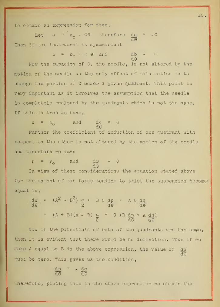
to obtain an expression for them.
Let a = a - therefore da = -'^
° deThen if the instrui::ent is symmetrical
b = bQ + ^. e and ^b = ^de
Now the capacity of G, the needle, is not altered by the
motion of the needle as the only effect of this iriotion is to
change the portion of G under a given quadrant. This point is
very impoctant as it involves the assumption that the needle
is completely enclosed by the quadrants which is not the case.
If this is true we hsve,
c = Cq and dc =
deFurther the coefficient of induction of one quadrant with
respect to the other is not altered by the motion of the needle
and therefore we have
r = r and dr =
deIn view of these considerations the equation stated above
for the moment of the force tending to twist the suspension becomes
equal to
,
dW = (A^-B^)a,+ BCdp_ + AGdqde 2 de de
= (A + B) (A - b; a + G (B d£ + A dq)2 de de
Nov; if the potentials of both of the quadrants are the saijae,
then it is evident that there would be no deflection. Thus if we
make A equal to B in the above expression, the value of dTde
must be zero, "^ais gives us the condition,
dp = - dqde de
Therefore, placing this in the above expression we obtain the


11.
following expression,
dW = (A - 3) Ra + B) a + G dqlL 2 deJ
If we now raise the potently.1 of the needle and both of the
quadrants by an amount p, the force tending to turn the needle
remains the same. If we do this the above eiuation becomes,
d2 = (A - B) r(A + B) a + C dq + ,Q ( a + dq)ld© L 2 de de
If this is co:.:pared with the equation above we see that the
condition for them both to be true is,
dq = - n:
de
As we know that both of the above equations are true therefore
the condition derived from them must also be true and the law
for the electrometer becomes if we sunstitute this condition in
the first equation,
ke = djY = a (A - B)(G - A + B )
de 2
From this we see that the sensitivity, if the potential of
either of the quadrants is small, will var^/ as a linear function
of the potential of the needle. This is often called the linear
relation.
In case the instrument is used hetrostatically , usually
B is earthed. Thus B = . Further A is so small in
comparison with G that it may be neglected wit lOut sensible
error. This gives the equation of the instrument used in this
manner as
,
e = K A G
In the ideostatic method we have G equal to either of the
potentials, of the quadrants, taking it e ]ual to A, the relation


12.
becomes,
e = K (A - B)^2
The experiments of Hopkinson and those of Aryton, Perry,
and. Sumpner and others showed that the equation for the electro-
meter's action could not be obtained by the simple assumptions
of Ilaxwell. A number of men have attempted the solution in
accordance with the experimental facts. Prominent among the new-
er discussions of trie law of the electrometer is that of G. W.
Walker in the Philosophical Magazine for 1903. He follows the
method of Maxwell but considers the conditions v/hich arise due
to the presence of the air gap. His method is as follows.
As before vie designate the potentials by A, B, and C,
the capacities by a, b, and c, and the coefficients of induction
t'y P, and r. Then we have as in Maxwell's development the
equations for the energy of the sj^'stem and the force which tends
to turn the needle.
W = 1 a A^+ 1 b B^+ 1 c pBG + qAG + rAB (l)
2 2 2
ke = A^da + B^db +C^dc + BGd£+AGdq'+ABdr (2)2 d© 2d© 2 d©' de d© d©
Now it is assuFied that the value of a can be expressed as
the sum of an infinite power series of the deflection.
a = + X^a^ (3)
Then as we assume a perfectly symmetrical electrometer, the
value of b must be the sane function of -© or
b = + (-1)^ e"" (4)
Again v;e assume that the value of q may be expressed by
another power series and thus

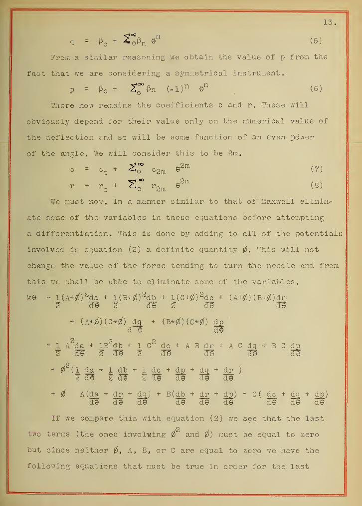
13.
Froiii a siiiiilar reasoning we obtain the value of p from the
fact that we are considering a symn.etrical instru.:.ent
.
p - Po + ^l^n (-1)^ (6)
There now remains the coelficients c and r. These will
obviously depend for their value only on the numerical value of
the deflection and so will be some function of an even power
of the angle. V/e v/ill consider this to be 2m.
c = Cq + ©2m
- = -o ^ ^o"" -2m
We must no'w, in a manner similar to that of Maxwell elimin-
ate some of the variables in these equations before att en.ptlng
a differentiation. This is done by adding to all of the potentials
involved in equation (2) a definite quantity 0, This will not
cheinge the value of the force tending to turn the needle and from
this we shall be abie to eliminate some of the variables,
k© = l(A+jZl)2da + l{B+0)^dh + l(G+0)2dc + (A+jZ^) (B+JZS}dr
2 d© 2 d© 2 d© d©
+ (A+0)(G + 2l) dq + (B+IZI) (C+jZJ) dpd © d©
= 1 A^da + IB^db + lc2dc + ABdr + AGdq + BGd£2 d© 2 d© 2 d© d© d© d©
+ 0^(1 da + 1 db + 1 dc + dp + dq + dr )
2d© 2d© 2 1© d© d© d©
+ jZl A(da + dr + dq) + B(db + dr + d£) + G ( dc + dq + d£)d© d© d© d© d© d© d© d© d©
If we coz-pare this with equation (2) we see that the last
two terms (the ones involving ^ and 0) must be equal to zero
but since neither ^, A, B, or G are equal to zero we have the
following equations that must be true in order for the last

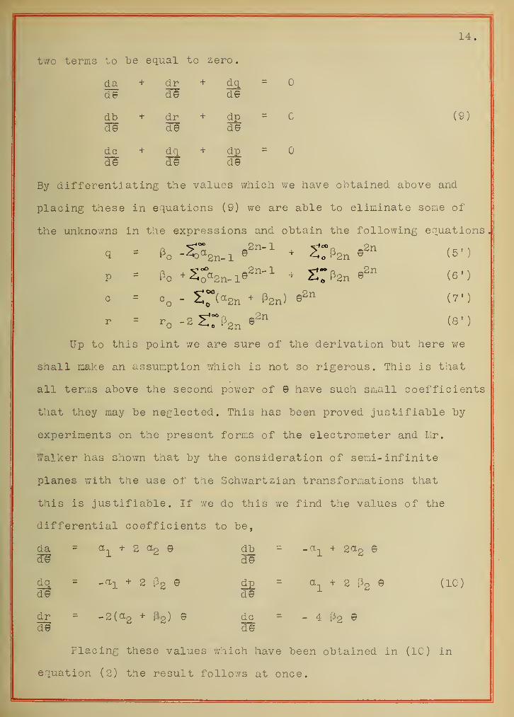
14.
two terms to be equal to zero.
da + dr + dq =
d© de d©
db + dr + dp = (9)dT© d© d©
dc + dq + dp =
d© d© d©
By differentiating the values which we have obtained above and
placing these in equations (9) we are able to eliminate some of
the unknowns in the expressions and obtain the following equations.
p = Po •^So^Sn-l©^"'^ + Srpgn (6')
o = o„ - 2:~{a2„ + (32„) 92" (7')
r = -2 Z^r^'gn (8')
Up to this point we are sure of the derivation but here we
shall make an assumption v/hich is not so rigerous. This is that
all terms above the second power of © have such small coefficients
that they miay be neglected. This has been proved justifiable by
experiments on the present forms of the electrometer and Hr.
Walker has shown that by the consideration of semi- infinite
planes with the use of the Schwartzian transformations that
this is justifiable. If we do this v;e find the values of the
differential coefficients to be,
da = a-j^ + 2 ccg © db = -a-|_ + socg ©3^ d©
dq = -a-L + 2 Pg © dp = a + 2 f3o © (10)d© d© ^
dr = -2(0.2 + Hg) © dc = - 4 P2 ®d© d©
Placing these values which have been obtained in (10) in
equation (2) the result follows at once.

15.
ke = a-,(A - D)(C - A+B)+ 9 ( a^ik-B)'^ - 2 P2 (C-B) (G-A) )
If we solve the expression for 9 we get,
© = ^1 ( A - B ) (G ^- A + B ) (11)k + 2 P2rG-B) (G-A) -ttgCA-B) 2 2
But as a usual thing the difference of potential between
tne quadrants is very sniall and further either potential is neg-
ligable in comparison with that of tae needle and thus the above
becouies
,
e = cr (A - B)^G (12)k + 2 ^2 ^
The theory thus given is apparently purely matheniatical and
does not explain the cause of the variation froc the linear
relation. However there are a few important deductions which
Hr. Walker draws from the theory which can be summarized as
follows
.
First, if there were no air gaps c would not vary with 9
as the quadrants v/ould then entirely enclose the needle. Thus
there could be no Voiriation of the capacity of the needle.
.Second. The capacity of the needle (c) is a. function of
the number of Faraday tubes which SLuape fromi the quadrants. Thus
we obtain two critical values of 9 v/hich will give us information
with regard to the value of c. These angles are and 7r/2
.
Third. From a study of the width of the needle in connection
with these critical values of c we are able to arrive at a certain
critical value of the number of degrees in the needle which
will cause the instrument to follow the linear relation. Thus
P2 can be made larger than zero, less than zero and equal to
zero. As a matter of fact there are electrometers which have each

16.
of these characteristics. They ;vill manifest themselves in
the sensitivity/- curves as indicated below.
2 Fig. 3
P2
Ordinary Quadrant Maxwell'
s
leiner
Electrometer
.
Electrometer
.
Electrometer.
In general the discussion thus far has led us to believe
that the sensitivity curve of an electrometer depends on both
the shape of the needle and tne size of the air gap together
with tie general dimensions of the instrument.
Dr. Seattle has given an explanation of the action of the
instrument which he has based on the idea of "control". Here
he postulates a controling couple acting on the needle either
opposing or aiding its deflection due to an electrostatic force.
The chief value of his method lies in the fact that it is appli-
cable to other forms of Electrometers than the q.uadrant. Further
it gives results consistent with the experimental data.
In this theory there are two couples 'A'hich act upon the
electrometer needle, f'he first is the controling couple v/hich
is tae total couple acting on the needle from all causes when it
is raised to the potential in question and the quadrants are all
grounded, ""he second is the deflecting couple. This couple acts
on the needle by reason of the fact that the quadrants are raised

17.
from zero to some definite potential difference.
The departure from the linear law is explained by the fact
that the controling couple is not single as one might think but
is the resultant of two couples working in tie same or in opposite
directions. It is evident that if the needle is at the potential
G and the qucidrants are earthec and v;e deflect the needle thru
the angle 9 there v/ill be certain forces which will tend to cause
its return to the zero position. One of these will be the couple
due to the torsion of the fiber and will be equal to K2 This
is termed the mechanical control. Then we will assume that there
is another couple y/hich is called the electrostatic control. If
this exists it will be proportional to the angle thru which the
needle is moved and if it is due to t le attraction of the needle
for its electrical image on the quadrants or is due to tae change
of this attraction with the deflection, it ;vill also be proportion
al to the square of C. As there mdv be an electrometer in which
this does not ©xist we will place a proportionality'" factor K2 i^i
the expression and in such a case this factor will beoom^e equal
to zero and the equation will still hold. That is in this special
case the controling couple will consist only of the mechanical
control
,
The deflecting couple v/ill be proportional to the product
of the needle potential amid the difference of potential between
the two pairs of quadrants. This is the ordinary lav/ of electro-
static attraction. Row the needle will deflect until these two
couples just balance each otner. If we equate the expressions
for the two couples we should h^.ve the law of the electromieter
.
^2® 1 ^^3 ® ^ ^''1 G (A - B)


18.
In tills equation v/e must place both tiie plus and minus si£ns
as we do not know .vhether or not the electrostatic control aids
or opposes the mechanical. Solving the above equation for 9
tnere results, \
© = Ki C ( A - B )
Kg f K3—C§
This, it is evident, is the same equation which we obtained
by the other methods. By a consideration of the instrument it
is possible, in general, to determine whether or not the sign
v/ill be positive. In case it is plus the instruiiient is said to
have a plus control,
(15)Emil Gohnstaedt has supported the view that the sensitiv-
ity of the electrometer depends alone on the size of the needle.
He bases his views on a series of experiments which he tried with
needles of different sizes. This seems to be rather an extreme
position as it is apparent that we cannot m^ake the air gap axiir
value tha.t v;e wish without changing the action of the instrument.
In general, the discussion of the electrometer taeory brings
out tae following points;
First. Except in very rare caese and what one might consider
the case of the ideal instrument, the law of Maxwell does not
exactly hold. However this does not prevent its being used as an
approximate formula for long ranges and as an exact formula for
short ranges. The actual meaning of the words long and short
must be determined for the special electrometer under consider-
ation .
Second. The cause for the variation of the equation fromi
the straight line cannot be definitely determined. It is ijiost


19.
liiely due to tnc sum of a number of causes rather than to any
single one. Among these causes are, the presence of the air gap,
size of the needle, symmetrical arraingment of the instrument,
electrical distribution, size and especially the proportion of
the quadrants, and others of which we have no knowledge.
Third. The correct formula for the electrometer under
ordinary working conditions is,
^ " K-i G (A - B )
^2 1 K3 ^
In which the K's are constants for the particular instrument v/ith
the particular adjustment and G is the needle potential while
A and B are the potentials of the quadrants. This formula has
been found to hold by every experimenter with a sensitive
instrument.


20.
IV. The Kanipulation of the Electrometer,
In the question of the manipulation of the quadrant
electrometer there are three things which v/e must take into
consideration. These are, first, the insulation of the instru.-.ent
and other pieces of apparatus which are to be used, second the
shielding of the apparatus from outside electrostatic disturbances,
and third the adjustment of the electrometer.
The insulation of the instrum-ent is usually well provided
for in its construction (that is in the Dolezalek form) . This
is done by mounting all of the connections and the quadrants on
either amber of sulfur. This, under ordinary circumstances provid-
es for the insulation of the instrument itself. However in damp
weather even this insulation is insufficient. As the apparatus
is usually at a temperature slightly lower than that of the
surrounding medium, it has a thin film of water condensed on
its surface. The only remedy for this is to either warm up the
room to a temperature above that of the outside to such an extent
that the humidity falls or to enclose the electrometer and such
other parts of the apparatus as is necessary in a vesjel with
some drying agent. Another method is to blow air which has been
passed thru a drying agent over the apparatus.
For the connections outside of the electrometer proper it
is always best to have themi up in the air and not touching
anything, if possible. Hov/ever v/hen this cannot be avoided, the
insulation usually used is paraffin. This is not a very good
insulator in many respects. It allows the dust to accumulate on
its surface and thus eventually becomes a conductor under the

21.
best circumatances . In addition to this it is a very poor dialect-
ric in the matter of absorption and when it once gets a charge it
it almost irapossible to remove. Further if it is desirable to
have the insulator keep its shape, it is almost impossible to
use paraffin as even at ordinary temperatures if it is not in
flat ceikes it will slov/ly take that form.
The question of insulation in electrostatics is one of
the most important questions involved. It is alto(;;ether different
from the case of electricity in motion. The insulation required
is almost unbelievable and the leakage that will take place even
under the best conditions makes good results very hard to obtain.
The question of the shielding of the electrometer from
stray electrostatic effects is another important question but
due to the fact that it can be almost completely removed it
only has to be mentioned with the method for its removal. Each
electrometer is protected in a.n excelent cianner from these dist-
urbances by the case in which it is enclosed. This case is grounded
and thus the quadrants are well protected from these disturiaances
.
This is not sufficient as the effects would cor.e in contact with
the terminals of the instrumxent and by these be directly trans-
mitted to the quadrants. This trouble is avoided by enclosing
all of the apparatus which is used inside of a large box covered
with a 7/ire screen and grounded. By the principle of electrostatic
shielding this almost completely prevents the entrance of any
electrostatic disturbances which would materially afect the
electrometer.
This screen is very remarkable in its shielding power. One
is able to electrify a rubber rod by rubbing it with cat's fur


22 .
and then discharge it directly against the screen in the form of
sparks and the electrometer will not be affected in t'le least.
However if the charged rod is brought in frr)nt of the small
opening which is left for the purposes of observation with tne
telescope, the deflection of the electrometer is very large even
tho no sparks are discharged.
What we mean by the adjustment of the instrument and when
the instrument is balanced is a very easy thing to tell from the
theory but how to tell a balanced instrument in practice is a very
difficult thing. From^ the theory of the electrometer, that is the
ideal instrument, we v/ould ssl^ that the electromieter would be
balanced if v/hen taere was a certain potential on the needle, it
would lie in the line of sym-.^etry and further when there was no
potential on the needle (tne quadrants at all times are supposed
to be grounded) the electrometer needle is still situated on this
line of symmetry. This perfectly defines the theoretical condition
of balance but in the instrument we must make a further definit-
ion.
There are, in general, three distinct steps which if they
are followed in the order given will insure what is called a
balance. In the first place, there m^ust be no deflection when
the potential in Question is placed on the needle. That is it miust
remain on the same line vv'hether or not there is a charge on it.
This first condition must be exactly obtained before further
work is attempted. This part of the balance is usually obtained
by leveling the instrument by means of the leveling screws at
its base. But before any adjustment is attempted the instrument
should be leveled and placed in the most symmietrical position


23.
possible by means of the eye. This step aids greatly in the
adjustment of the instrument.
If we suppose that the first condition for the balance is
fulfilled the next step is to make sure that the line to which
we have adjusted is the true line of symmetry. This, in general,
is not the case and we must change our zero line until it coincides
v/ith the line of symmetry. This is done by jblacing a certain
potential on one of the quadrants and keeping the other grounded
and taking the deflection. Then place the same potential on the
other quadrant keeping the first grounded and observe the deflect-
ion. The result should be that in both cases we get the ssune
deflection. If this is not the case, the torsion head of the
instrument must be rotated until this is true. This condition
should be attained as closely as possible but it is hardly ever
possible to fulfill it as well as is desired due to the fact that
the instruments are not supplied with a tangent screw on the
torsion head as they should be.
After the second condition has been fulfilled it is well
to go back and find out t;hether or not the first one is also.
The third condition is sometimes already obtained by the first
two but at other times it will take a rotation of the instrument,
a raising or lowering of the needle in tne case or something
else to obtain it. This condition is to place one pair of
quadrants on ppen circuit while the other pair is grounded and
then raise the needle to the desired potential, if this gives no
deflection then the instrument is balanced, if not it must be
so adjusted that there is no deflection in this case.


24.
It might seem that this is a very tedious process and
certainly it is but even yet the electrometer is not in balance.
However this is usually tahen as a balance and for most purposes
this will be sufficient.
It will be seen in the study of t :e contact difference of
potential that the two quadrants are at all times at a different
potential. This can only be studied when both of the quadrants
are grounded and the needle raised to the required voltage. Thus
we at once suspect that tnis would play an important part in the
question of the balance of the instrument.
If after we obtained the balance as indicated above we should
eitner increase or decrease the potential of the needle we would
find that the balance no longer existed. Further if we should
keep the same numerical value of the needle potential but reverse
the sign we v/ould find that tne balance was destroyed by an
amount equal to the deflection at the sensitivity of the
electrometer for twice the contact difference of potential. Thus
we see that the balance of the electrometer by these conditions
trys to eliminate the contact difference of potential and thus
the balance is only good for a certain value of the needle_
potential
,
The absolute balance of the electrometer as described for
the ideal instrument v/hich would be good for all needle potentials
is impossible due to the presence of the contact difference of
potential. The result of this is that the needle never lies in
the line of symmetry of the quadrants and therefore at very high
potentials the angle betv/een the line of the apparent zero and
the line of symmetry v/ould be expected to become very large.
I

25.
However Prof. A. Anderson in a careful study of trie variation
of the angle between the line of syrmrietry and the apparent zero
of the instrument has proved that the variation takes place in
such a manner that at the point of maximum sensitivity the needle
moves of its ov;n accord into the line of symmetry making this
(16)angle zero.
There are a few things which might be pointed out in
connection with the electrometer. In the first place it is
(17)possible as sho?/n by Schultze to make an instrument which
will follow the law of Taxwell at least up to very high potentials
by an adjustment of the number of degrees which are contained
in the needle. He also gives curves showing the effect of differ-
ent sized needles on the particular electrometer in which he was
interested
.
By means of the period of the needle we can tell whether,
for most electrometers , the needle is subject to a positive or
negative control. This is due to Dr. Beattie, If the period of
the instrument increases as we place higher potentials on the
needle we have a negative control. In the same manner if there
is a positive control the period will decrease with higher
potentials. As we might reasonably expect if the controling
couple (electrostatic is alv/ays refered to here) is zero as
in the case of the ideal electrometer then there will be no
change of the period with either an increase or decrease of
the needle potential.
I

26.
V, Characteristics and Experiments.
There are four quantities which might be called the
characteristics of the electrometer. These are the sensitivity,
the contact difference of potential, the variation of the
capacity wit'n the deflection and the capa.city itself. 'I'he first
and third of these are intimately connected. In fact it is the
variation of the capacity with the angle of deflection that
determines t.ie sensitivity. From the experimental side of the
question all four are of great importance and if there is to be
any accurate measurments , they must all be considered or by some
method eliminated from the problem.
The sensitivity of the electrometer is defined as the
fraction of a volt necessary to cause a deflection of one miu.
on a scale placed at a distance of one meter from the electrometer.
'^his question has been discussed to a certain extent in the preced-
ing paragraphs but its great importamae will allow a more
detailed discussion.
The sensitivity depends on almiost everything about the
electrometer but the main factor is the torsional constant of
the suspension. In addition to this it will depend on the
construction of the electrometer, the quadra.its, their capacity,
the variation of the capacity with tiie angle of deflection and
we may even think of it depending on the square of the needle
potential from the previous discussion of the equation of the
instrument as well as being directly proportional to the first
power i>f this potential. However if all of the other details of
the construction are normal the great factor is the torsional


27.
constant of the suspension.
Tnus for the sake of sensitivity it is very desirable that
a Tiuartz suspension be used. Cn the other hand, if '.ve do use
such a suspension, as it is insulating, we experience great
difficulty in charging the needle and keeping it charged. This
(10)has been remedied in part by Bestelmeyer and others by
covering the quartz suspension with some metalic covering which
will conduct electricity to the needle. However the best conduct-
ing suspensions are made of phosphor bronze which is naturally
conducting and has very good elastic properties. The quartz
fibers can also be made conducting by covering them v/ith some
hydroscopic solution and made conducting in this manner they
must be kept damp which is very undesirable as in order to
avoid leakage one must have the atmosphere as dry a.s possible.
The value of the instrument is not 7/holly dependant on
the sensitivity and for this reason the mere expression of the
sensitivity of tne instrumient does not give an idea of its
actual value. The other tv/o determiining factors in the instrument
are first the manipulation and in this connection the definite-
ness of the results. That is if we have an instrument which is
very sensitive and yet the deflections are not dependable we had
just as well for riost purposes reduce its sensitivity until the
results can be depended upon. Second, in a large measure the
ease of mianipulation influences the results. In many cases it is
necessary to have an instrument in which the readings can be
taken in rapid succession and in these cases it i.^ almiost imposs-
ible to use an Instrumient of high sensitivity, Furtner in a large
number of cases the meaning of the sensitivity of the instrument


28.
must be evaluated with its capacity in mind. This is especially
true in the case of radio-active work. If we have an instrunient
of high sensitivity in order for it to be of value it must have
a small capacity that is not more than ICO cm.
Of the other characteristics of the electror-ieter in majiy
respects tne most important are the capacity and the variation
of the capacity ?/ith respect to the angle of deflection, We
know from the theory of the instrument that the capacity must
change with the deflection but to measure that change is almost
impossible
.
There have been given a number of methods for the measurment
of the capacity of the electrometer. The method of sharing charge,
^^^^Norman Campbell's metiind ,^ ^ and the method of continuous
charge and discharge ^^"^^ are the chief of t.iese. However all
of these are quite inaccurate and unsatisfactory so that a study
of the var-iation of the capacity is almost impossible by any of
the above methods.
In 1909 Pulgar and 7/ulf ' devised a method for the measure-
ment of the capacity of t ie electrometer by mea.ns of using a
string electrometer of the v7ulf type. This method was so success-
ful that they found that they could extend their method to the
measurement of the variation of the capacity with the deflection
and further found the average variation for a number of readings
which they took to be .C19 cm, per 1*^.
They concluded that the idea of the capacity of the electro-
meter was one which was subject to a number of interpretations.
So after defining it they developed a general theory of tne inst-
rument on the principles of dynamics.


29.
Not only is the knowledge of the capacity and the variation
of the capacity important from the standpoint of the sensitivity
and the equation of the instrument but its great impcrtance lies
in the use of tie instrument in radio-activity and photo- electric
studies where it is necessary to know the capacity in order to
determine the quantity of electricity and the current.
There are certain phenomena which justify us in t'ninking
that even in case bot:i pairs of quadrants are grounded in the
ordinary electrometer yet there exists a difference of potential
between the quadrants. This was first discovered and discussed
(23)by Plallwachs in 1886 and has been observed again and again
since then. It is explained by the fact that the pieces of metal
which compose the two madrants are not treated in exactly the
same manner in their manufacture and thus there is a certain
difference betv/een them (explained by Campbell as a difference
of the concentration of the electrons within them) . Thus in a
sense ^ve have two different metals near each other. This gives
somet.iing similar to the Volta effect and tnus the difference
of potential is indicated by the electrometer.
Let it be assumed that when both of the quadrants are ground-
ed there exists a small potential difference jzl. Further let us
suppose that when there is no potential on the neodle its zero
position is determined. Now if we place a known potential on the
needle there will be a deflection due to the potential difference
i between the quadrants. This expression as we keep both of the
quadrants grounded is given for the deflection,
% = .LlA^K4 + G'^


30.
From this expression we should be able to calculate the value
of This is not tne case as v/111 be shown later. In the first
place there is another effect which would to a certain extent
mask this effect. It is the shift of the zero toward the position
of sjrniiTietry which is discussed in Anderson's work. Then the :uore
inpoEtant reason is that v/hen we define the condition of balance
for the electr )meter we state that no such notion shall occur.
Thus if we have balanced our instru...ent it is impossible that
such a state occur,
/e shall suppose that there is such a deflection and in
a case in which there is none then the above deflection will become
equal to zero. Now change the value of G to a -G. That is simply
reverse the term.inals of the battery and we v/ill have a different
deflection,
% = - Ki, G
K4 + G^
If we subtract these two expressions we have,
®o - ®; = 2 Ki c o
From this expression we can easily find the value of ^. This
also has the advantage of being free from the error m.entioned
above due to the motion ofthe needle toward the position of
symmetry as can be shown by taking this into the equation. In
most cases tne value of has been found to be of the order of
one one hundredth of a volt.
The following graphs will show the value of the contact
difference of potential and that it is constant for any one
instrument. There are a number of interesting facts evident from


the graphs which will be discussed in connection with them.
Thruout the following experiments the instru. .ents used
were those manufactured by 'Y. G. Pye and Go. These ins tru^.^ents
are listed as "P. L. 3659 " of which series G.and D. v/ere used.
The dimensions of tae instru. .ents were as follows;
External Q,uadrant Diaixieter
External Quadrant Height
I^ength of Suspension
(Phosphor bronze)
Length of Needle
'.Veight of Needle including
mirror etc
Angle included by Keedle
ThiG'mess of metal composing
the quadrants
5.53 cm.
1.08 cm.
7.9C cm.
4. CO cm.
.230 gr.
70°
(Approx.
)
(Approx .
)
.16 cm (Approx.)


32
Graph I
.
This illustrates the action of the niodern quadrant electro-
meter. Here is sho'vn the relation betv/een the deflection for one
standard Weston cell against the potential of the needle. It is
&t once evident that the instrument follows the law of Maxwell
at least as far as the investigation has been carried.
From this graph we can conclude that the linear relation
holds in the modern Dolezalek electrometer up at least to a
needle potential of ISO volts.


34.
The Sens iuivitj^ Curve of t:ie Electrometer.
T e 1 X . -Eef 1
.
9 ^ v> r" Q
4 1^ Q Q Q 24 19 81 . «J
, 617 c w 23 90 1. 10 1 70
TO O K 22 . 50 2 70 « c^
i r .A '7 21 . 70 3 30
•7 p T• v> i. . "Jl 21 .05 3 95 A P,
r L ,'±<J 19 45 5 . 55 P> r
«^ V ,%o "7 op. 19 .30 5 . 70 .
"^/t "7O^r . / iJ . 18 ,00 7.00
"A /I nn pp 16 . 2d 8 75 0.0/
l~. IP 15 20 9 .80
4 / . ^ 00 . ±0 11 1 RX J. . ± 10 85 11 PIP
"7 P 1 'sP. 1 1 50 1 1 opX X . bU
Do . U 1 AP 1? 48 10 OAX;i . cO
1 A OP 11 5
'
1 3 45 1 r? po
DO./ 1 R PP Xw » ^ V-/ T 4 40X # ± W 1 1 7P
/ . D /IP on 1 R PPID . bU 9 80 X # <o W 1 R PRX D . U D
79 A •±1.0 1 C- R±U . D 9 or 1 r 00 1 1^ PiOXU , Uii
"7^ 1 Q Ok10 . .iD 8.50 16.50 1 "7 "7
79.3 44.35 19.35 8 .2D 16.75 13 . 05
83.7 45.30 20.30 7,00 18.00 19.15
88.0 46.80 21.30 0.30 18 .70 20.25
92.3 48.20 23.20 5.90 19.10 21.15
96.70 49.2b 24.30 5.00 20.00 22.15

c
ICl.C
ICS ^8
107.
G
111.5
116.3
123. C
13C.1
138.3
14© .
154. G
162 .2
+ Defl.
47 . 9C
48.95
50.00
53.10
54.1
55. 3C
56.50
58.59
60.60
63 . 00
G5. 40
68.10
9
22.90
2 o « Q 5
25.00
28.10
29.1
30.30
31.50
33.59
55,60
33.00
39.60
43.10
- Defl.
1.8t?
.80
-1.00
-1.00
+ .70
- .05
-1.50
-2.50
-4.00
-5.60
-7.05
-7.55
e
23,15
24.20
25.05
26.00
24.30
25.05
26.50
2^.50
29.00
30.60
32.05
32 .55
Aver. 9
24.07
25.02
27.05
26.70
27.65
28.00
30.54
32.30
34.30
35.83
37.82
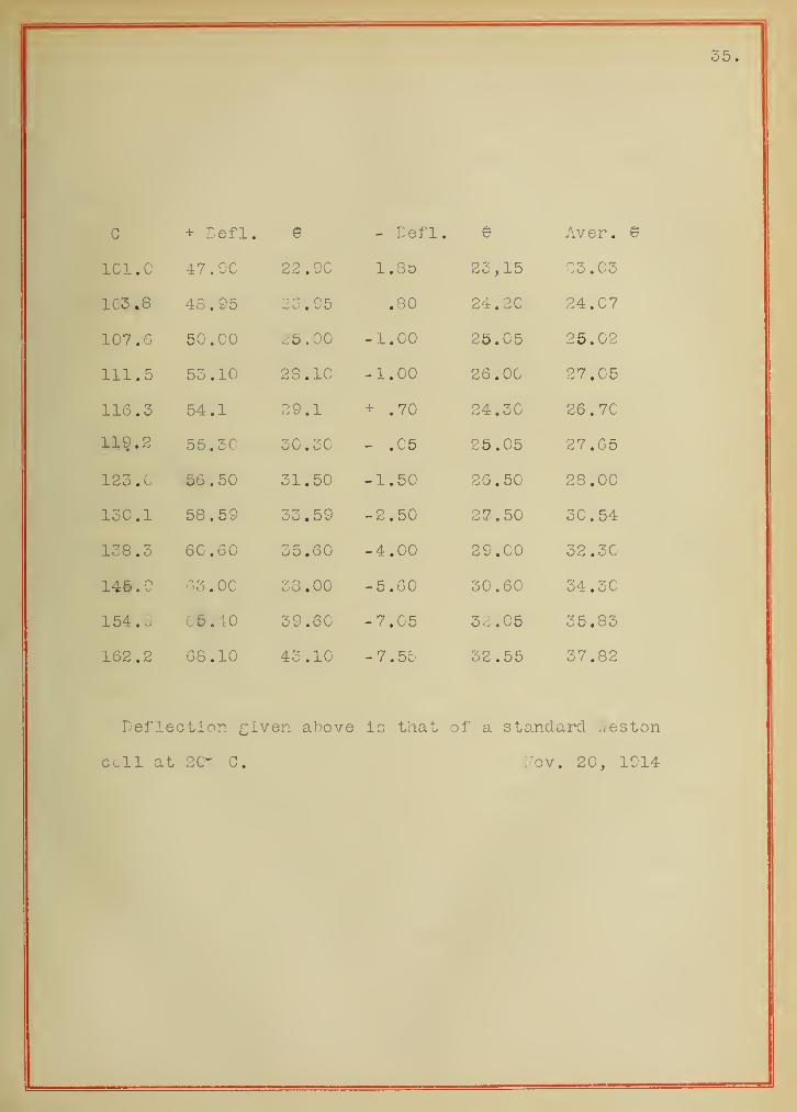
Deflection given above is that of a standard. Weston
cell at 20'- C. Nov. 20, 1914

36
,
Graph 2.
In this investigation the needle potential has been in-
creased to almost twice that heretofore studied. This has
given the further result that the law of Maxwell can be taken
as correct up to at least 270 volts. It may seeiii that these
curves show a tendency to curve upward a snail amount but the
variation from the straight line is so small that it is as
fa2? as we can judge from these curves not present. All of the
variations from the straight line in these curves are within
the experimental error.
The second feature of this investigation is shov/n in the
curve representing the contact difference of potential. The
quantity 'which is plotted is in reality twice the actual value
of the deflection for the contact difference of potential.
It 7/ill be seen that this is al^o a straight line. When
the actual value of the contact difference of potential isf
figured as is shown on the data sheet it is found to be a constant
no matter what the potential of the needle may be.
The quantity plotted as deflection is tiat obtained for
.05 volts. The defl-ection plotted is the average of four read-
ings two taken to the left and two to the right. Two of the^e
are obtained y/ith a certain polarity of the needle by reversing
the standard cell and the other two are obtained in a similar
manner with the polarity of the needle reversed.


COo o o o
(X!
o
Leflection in mra.


38.
Deflection for .05 v.
With
Contact Difference of Potential
Value
c + G -G Average ^0 In mm. In Volts
12 3 .60 3.35 3.47 15.89 15.74 1.50 .0106
25 7.00 7.40 7 . 20 16.00 15.73 2.70 .0084
37 10.50 10 .15 10.32 16.20 15.70 5.00 .0093
49 13.75 13.65 13.70 16.35 15.75 6.00 .0109
62 17.2'5 16.80 17. Og 16.60 15.85 7.50 .0110
75 20.75 20.45 20.60 16.85 15.95 9.00 .0107
86 24.00 23.50 23.75 17.10 16.10 10.00 .0105
93 27.50 27.25 27.37 17.43 16.25 11.80 .0107
lie 32.65 30.40 31.52 17.73 16.41 13.20 .0105
118 33.10 32.50 32.80 17.99 16.52 14.70 .0112
133 37.60 37.10 37.35 18 . 40 16.80 16.00 .0107
146 42.50 41 .50 42.00 18.85 17.05 18.00 .0107
161 19,30 17.27 20 .30 .0105
186 54.85 53.50 54.17 19.95 17.60 23.50 .0108
232 70.00 68.85 69.42 20 .60 17.55 30 .50 .0109
248 75.25 72.75 74.00 20 .60 17.35 32.5 .0109
Volts imn. mm. mm. cm. cm. mm. volts
.
Average value of the contact potential difference
is found to be by the above data ,01052
Feb. 2, 1915.

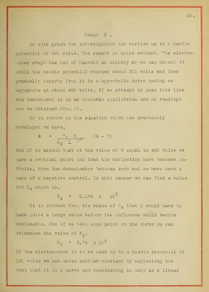
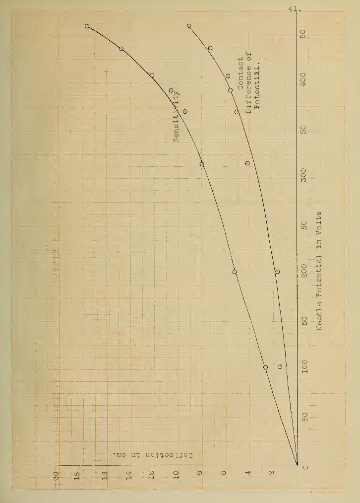
Graph 3 ,
In tliis graph the investigation was carried up to a needle
potential of 460 volts. The result is quite evident. The electro-
:.:eter obeys the lav/ of Maxwell as closely as we can detect it
until the needle potential reaches about 300 volts and then
gradually departs from it to a hyperbolic curve having an
asymptote at about 480 volts. If we attempt to pass this line
the instrument is in an unstable eciuilibrium and no readings
can be obtained froi^i it.
If we return to the equation v/hich was previously
developed T/e have,
© = ^^-1 G (A - B)
Nov/ if we assume t lat at the value of S equal to 480 volts we
have a critical point and that the deflection here becomes in-
finite, then the denominator becomes zero and we have here a
case of a negative control. In this manner we can find a value
for which is,
= 2.184 X 10^
It is evident from the value of K4 that G would have to
have quite a large value before its influence would become
noticeable. Wow if we take some point on the curve we can
determine the value of .
KjL = 9.74 X 10^
If the electrometer is to be used up to a needle potential of
150 -colts we can write another constant by neglecting the
fact that it is a curve and considering it only as a linear


function. In t'.iis case we would have,
e = .422 G (A - B)
This value of 9 will be in LTim. on a scale at a distance
of one meter from the instrument.


42.
Deflection of .05 v. Contact Difference of Potential
With ValueC +G -C Average 9q In mni. In volts
1C5 27. 5C 27.25 27.37 27.50 26.00 15.00 .0137
205 52.40 52.75 52.65 50.00 28.17 17.30 .0075
315 80.35 80.00 80.17 33.75 29.50 42.50 .0132
370 95.50 91.00 95.75 32.10 27.00 51.00 .0132
392 105.50 108.00 106.75 29.40 23.80 56.00 .0131
415 122.00 125.00 123.50 25.30 19.50 58.00 .0115
437 148.50 147.50 148.00 19.60 12.30 73.00 .0125
461 177.50 177.50 17.15 8 .00 91.50 .0126
The average value of the contact difference of
potential as obtained from the above data is .6122 volts.
Feb. 6, 1915.


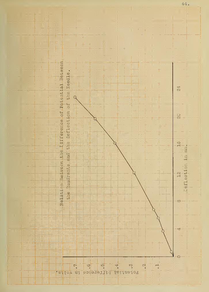
Graph 4 .
This shows the calibration curve of trie electrometer.
In this curve the instru;:.ent with a certain potential on the
needle has certain differences of potential placed ac ross the
quadrants and then according to t!ie theory if x^e plot the
differences of potential against the deflections we should get
a straight line.
The explanation of the reason for not obtaining a straight
(24)line as shown in the graph has been given by Geiger, . The
reason which he gives is that the instrument is not perfectly
balanced. This must be somewhere near the correct reason as it
cannot be explained as due to the terms that were neglected in
the development of the lormrala as even if we consider these
they will riot account for any appreciable part of this
variation
.

44


45
CO
CO
CD
in
St
CO
to
oo
•
to
Oito
oo
Oto: Cv!
c -01
oo
lO oLO
lOo


The Calibration of the Electrometer.
Fraction 8 d V k
C.Ol 25.75 .0.75 .014203 .001893
U . Ob O Q '7(^CO . / ,\j 1 i-Ul rim oi A
0.08 30.65 5.65 .11361 .002010
0.10 31.85 6.86 .14202 .002070
0.20 37.11 12.11 .28404 .002345
0.30 41.35 16.35 .42606 .002605
0.40 44.90 19.90 .56808 .002854
0.50 48.05 23.05 .71010 .003080
cm. cm. volts volts/mra.
Standard Clark Cell used in the calibration at a temper-
ature of 25" C, having therefore a voltage of 1.4202 volts. This
was calculated by the formula of JM.ger and Kahle (Reichsans talt )
.
Distance from mirror to scale was 2030 mm.
G 'was equal to 61.5 volts
The formula which gives the E. M. F, of a Clark cell at
a certain temperature as given by JS.ger and Kahle is;
e = 1.4328 - O.C0119(t-lo° ) -0.000007 (t - IS^' )^


47.
The facts that are known viitn regard to the quadrant form
of the electrometer may be summarized under five heads.
First. It is definitely knov/n that the equation for the
electrometer which will be applicable in all cases is,
9 = Kl G ^ (A - B)
K2 1 K3 g2
In some cases tne value of K3 will bo zero and we have the case
which Maxwell discussed. In others it v/ill take the negative
sign and we consider i t as having a negative control. In this
case it is usually possible to get the greatest sensitivity.
Finally it may take the positive sign, thus having a positive
control. If this is the case after reaching a maximum sensitivity
at a v/ell defined voltage of the needle its sensitivity will
fall off gradually.
Second. The reason for the departure from the linear
relation between the sensitivity and the needle potential is
not clearly understood. However it has been possible to make
instru::.ents , by experiment, which will follow the linear law
up to quite high potentials. The method of doing this has been
to construct an electrometer with as small air gaps as possible
and then to make needles v/ith different lengths and having an
included angle of a varying number of degrees and study their
action until the critical length and angle v/ere found for that
dimension of infltrument.
Third. The methods for the measurment of the capacity of
the electrometer are very unsatisfactory. The variation of the
capacity with the deflection has been measured by the aid of a
77ulf string electrometer by Pulgar and 'iVulf.


48.
Fourth. There is present in the electroiiieter a contact
difference of potential. This has been found by all experimenters
on this question to be of the order of one one hundredth of a
volt. It seems odu that in all electrometers it should have
so nearly the same value V7hen the instruments must have been
made under widely different conditions and of very different
materials
.
Fifth. It is impossible to obtain a perfect balance of
the electrometer due to the presence of the contact difference
of potential. In the balance usually obtained this factor is
eliminated but due to this attampted elimination the balance
is only good for the definite needle potential for which it
was obtained.

49
R E F S E E II C E 3 .
Lord Kelvin
(a) Papers on Electrostatics and Magnetism. Sir W. Thomson
XX Electrometers and Electrostatic Measurraent Pages 264
(b) British Association Reports on Electrical Standards.
Pages 219 - 324
These references contain Lord Kelvin's ov/n description
of his instrument together with a brief discussion of
other forms invented up to that time.
J. Clerk I^axwell, Electricity and Magnetism Vol. I.
Chapter XIII Electrostatic Instru.-ients Pages 317 - 53
This is a most excellent development of the theoret-
ical side of the question and has been follov/ed by almost
all of the later developments of the theory, in method
at least
.
Lr. John Hopkinson The Quadrant Electrom.eter
.
Phil. Mag. (5) 19, 291, 1885
This paper describes the action of the electrometer
v/ith a bifilar suspension and arrives at a formula which
is m.ore nearly correct for this form than the linear
relation
.
Aryton, Perry, and Sumpner The "iuadrant Electrometer.
Phil. Trans. 182, 519, 1891
This is a very interesting article which discusses a


5C .
a further development of t.ie bifilar suspension and
strives to nialve an instrument which v/ill follow the
law of Maxwell.
(5) Dr. F. Dolezalek The '^^uadrant ^lectroneter
.
(a) Zelt. Elektrotrcn. 1896 pages 471 - 472
(b) Ann. der Phys. 26, 312, 19C8.
These contain descriptions of the form of the electrometer
of which Dolezalek together with Nernst was the inventor.
(6) G. 7/. '.Valker The Theory of the Quadrant Electrometer.
Phil. Mag. Vol. 222 (6) 19C3 pages 238 - 25C
This contains the development of the theory of the
electrometer and also a certain amount of discussion on
its characteristics.
(7) Dr. R, Beattie The Quadrant Electrometer.
(a) Electrician 65 729 1910
(b) Electrician 69 233 1912
This contains not only some experimental 7/ork but also
the developmient of the control idea. lie also develops the
control idea for the capacity of an electrometer in
series with a capacity as in the case of radio active
measurmenibs
.
(8) Sir J. J. Thomson On the Charge of Electricity Carried
by the Ions Produced by Rttntgen Rays.
Phil. Mag. 239 23 330 1898


In order to do the work under consideration the
author found that it wa.s necessary to have a better
knowledge of the capacity of the electrometer. In this
paper the theory is developed for the capacity and also
a method of measurment is given.
(9) L:'. T. Edelmann
Carl's RepertoriuiL 15 46 1879
This contains a description of the Edelmann modification
of the original form of the quadrant electrometer.
(IC) Prof. Boys Note on Recent Forms of the Electrometer.
Electrician 27 266 1891.
This is nothing but a short note in which the Boys'
forms of the quadrant electrometer are as briefly
described as possible but ther-e is no other description
available.
(11) F. Paschen Ein klelnes empfIndllches Elektrometer _
Phys. Zeit. 7 492 1906
This contains a description of the small form of the
quadrant electrometer v/ith vertical quadrants which has
reached a high sensitivity. In this will be found the
dimensions and actual construction of the instrument,
(12) C. Ilililly Ueber ein Elektrometer von hoher Empfindlichkei t
.
Phys. Zeit. 12 237 1913


52.
This is a description of the manipulation and
construction of an electrometer of the Kleiner form.
This has reached tne highest recorded sensitivity. Here
will also be found the dimensions of the instrument,
(13) G. Hoffmann Ueber ein hochempf indlicher Elektrometer tLSv,
Phys. Zeit. 13 481 1912
A discussion of the author's Hankel form v/ith a
short blade for a needle and its application in the
study of the ionizing power of the cl particles from
radium.
(14) The Binant form of electromxeter
,
(a) R. Blondlot et P. Curie 3ur un electrometre
Astatique
.
Gomptes Rendus 107 864 1888
(b) Oevres de P. Gurie publiees par les soins de la
Societe Francaise de Pli^isique 586See reference (32)
(15) Emil Gohnstaedt Ueber die Empf indlichkei t des ^^uadrant-
Elektrometers
.
Phys. Zeit. 7 380
This is a short note giving the autior's views on
the theory of the instrument and a little experimental
data.
(16) Prof. A. Anderson The Behavior of the Quadrant Electro-
meter.


53.
Phil. Mag. 239 (6) 380 1912
This takes up the theory from the same stand-
point as 7/alker in fact it assumes a faiuiliarity with
Mr. V/alker's article. This contains a furtner study
of the characteristics of the instrument.
(17) H. Schultze Elektrometrische Untersuchungen
Zeit. ftir Ins tru;-.entenkunde 26 147 1906
This contains an excellent description and dis-
cussion of the influence of the number of degrees in
the needle on the action of the electrometer.
(18) Bestelmeyer
Zeit f-lir Instk. 25 339 1905
This is a discussion of a method for me.king
quartz fibers conducting.
(19) 'ii7atson A Text Book of Practical Physics
(a) Electrometers page 569 at seq,
(b) iuartz Fibers page 547 et seq.
This book contains both an excellent discussion of
the manufacture and manipulation of quartz fibers and
a short discussion of tie quadrant electrometer.


54.
(2C) Norman Campbell Note on the l^easurment of Capacity.
Phil. Mag. 237 42 1911
In this article the author gives a method for the
measurment of the capacity of either the electrometer
itself or of the electroii tatic system consisting of the
electrometer and a capacity such as an ionizing
vessel
.
(21) R. K. McClung The Conduction of Electricity Thru Gases.
Pages 9 - 35 .
This contains an excellent discussion of the man-
ipulation of the quadrant electrometer. This with the
book by Makower and Geiger and the text of 7/atson are
almost the only books which attempt to give anything of
the manipulation of the instrument.
(22) J. del Pulgar and Th. Wulf. Algem.eine Theorie Elektrostat-
ischer Messinstrumente mit besonderer Berticksichtigung
des Quadrantelektrometer
.
Ann. d. Phys . (4) 3C 697 - 718
This contains a development of ..'hat the authors
consider the most general theory of the instrument. It
also contains a study of the variation of the capacity
with the deflection by means of the V/ulf string
electrometer
.


55.
(23) V/. Hallwachs Elektrometrische Untersuohungen
Ann. Phys. u. Ghemie 29 1-47 1886
This is a very £ood. article and is the first
mention of tne evaluation of the contact difference of
potential. It also contains other interesting data.
(24) Ilalvower and Ceiger Practical I.Ieasurnients in Radio-Activi ty
.
Pages 3 - 6
.
Tnis contains in addition to an excelent treatise on
the manipulation of the instrunent a very snort and
yet complete review of t le control idea developed by
Seattle
.
(25) H. 3choll Die Justierung des C>uadrantelektronieters
,
Phys Zeit. 9 915 19C8
T/iis is a discussion of txie instrument more from the
experimental side, hov/ever there is a certain a;uount of tne
th.eory necessarily included.
(26) E. Crlich. Die algemeine Theorie des ^uadrantelektrometers
.
Zeit. fiir Instrumentenkunde 23 97 19C3
This is an attempt to obtain a solution for the
equation of any electrometer that may be devised.
(27) F. Harms.
Aim. d. Phys. 10 816 1903
A discussion of the capacity of the electrometer and
the change of the capacity with the deflection of the needl(


56 .
The follov/ing books contain the usual development of the theory
in better than the ordinary way.
(28) 3. G. Starling. Electricity and Magnetism 157 - 162
(29) J. H. oceans. I'athematical Theory of Electricity and
Magnetism. Electrometers 105 et seq.
(3C) Henderson. Practical Electricity and Magnetism V.I 209.
(31/ F. Dolezalek Ueber ein hochempfindliches Zeigerelektromete]
Zeit. Flir Instrumentenkunde 26 292 1906
A discussion of a development of the quadrant type
into a pointer electroiiieter
,
(32) F. Dolezalek
Ann. d. Phys . 23 312 19C6
See reference (14)
This and the references given under (14) are a
discussion of tie binant form of the electrometer.
The first two parts of (14) are the same the second
being a reprint in the collected v/orks of P. Curie.


Related Documents