1 THE SCIENCE OF MIXING AND IMPROVING WATER QUALITY IN WATER STORAGE TANKS Michael J. Duer, P.E. Chief Engineer, Tideflex Technologies., 600 North Bell Ave., Carnegie, PA 15106. (412) 279-0044 phone, (412) 279-5410 fax, E-mail: [email protected] ABSTRACT Water storage tanks and reservoirs are a critical component of distribution systems, yet they can pose a significant challenge for water utilities as they often have a negative impact on water quality. Water quality problems can develop due to low turnover and/or inadequate mixing resulting in short-circuiting. While the benefits of maximizing tank turnover to minimize water age are generally understood, it is only recently that extensive research on mixing characteristics of storage tanks has been undertaken that has provided insight on what causes water quality problems and expertise in designing inlet/outlet pipe configurations, or mixing systems, to achieve complete mixing and maintain water quality. This paper discusses the science of mixing applicable to all styles of storage tanks including circular and rectangular reservoirs, standpipes, and elevated tanks. Mixing characteristics of storage tanks are quite complex due to the closed geometry of the tank, the effect of inlet flow momentum, and the effect of buoyancy differences caused by temperature differentials. Computational Fluid Dynamics (CFD) and Physical Scale Models are utilized to illustrate the effect of various inlet configurations, inlet momentum, and temperature differentials on the mixing processes within storage tanks. The modeling results demonstrate how water quality problems develop, and how they can be corrected with a properly designed piping/mixing system. KEYWORDS Mixing, Short-Circuiting, Stratification, Buoyant Jet, DBPs, Water Quality, Water Age INTRODUCTION Recently adopted and proposed water quality regulations, such as the Stage 2 Disinfection Byproducts Rule (DBP), have caused many utilities to further scrutinize their distribution systems to identify and correct problematic components of the system. Distribution storage facilities are a strong focus of attention since they generally have a negative impact on the system with regard to water quality. Distribution reservoirs are required for flow equalization, to sustain pressure, to hold several days of storage for redundancy, and provide fire and emergency storage. In order to achieve these goals, reservoirs need to have adequate storage volume based on worst-case hydraulic scenarios and also must be designed to supply the system allowing for future community growth. Some of these design goals are contrasted by what is generally required to maintain safe drinking water. Common problems in storage tanks and reservoirs are the loss of disinfectant residual, bacteria regrowth, spikes in DBPs, and nitrification (chloramines), resulting from hydraulic short-circuiting,

Welcome message from author
This document is posted to help you gain knowledge. Please leave a comment to let me know what you think about it! Share it to your friends and learn new things together.
Transcript

1
THE SCIENCE OF MIXING AND IMPROVING WATER QUALITY IN WATER STORAGE TANKS
Michael J. Duer, P.E.
Chief Engineer, Tideflex Technologies., 600 North Bell Ave., Carnegie, PA 15106. (412) 279-0044 phone, (412) 279-5410 fax, E-mail: [email protected]
ABSTRACT
Water storage tanks and reservoirs are a critical component of distribution systems, yet they can pose a significant challenge for water utilities as they often have a negative impact on water quality. Water quality problems can develop due to low turnover and/or inadequate mixing resulting in short-circuiting. While the benefits of maximizing tank turnover to minimize water age are generally understood, it is only recently that extensive research on mixing characteristics of storage tanks has been undertaken that has provided insight on what causes water quality problems and expertise in designing inlet/outlet pipe configurations, or mixing systems, to achieve complete mixing and maintain water quality. This paper discusses the science of mixing applicable to all styles of storage tanks including circular and rectangular reservoirs, standpipes, and elevated tanks. Mixing characteristics of storage tanks are quite complex due to the closed geometry of the tank, the effect of inlet flow momentum, and the effect of buoyancy differences caused by temperature differentials. Computational Fluid Dynamics (CFD) and Physical Scale Models are utilized to illustrate the effect of various inlet configurations, inlet momentum, and temperature differentials on the mixing processes within storage tanks. The modeling results demonstrate how water quality problems develop, and how they can be corrected with a properly designed piping/mixing system. KEYWORDS Mixing, Short-Circuiting, Stratification, Buoyant Jet, DBPs, Water Quality, Water Age INTRODUCTION Recently adopted and proposed water quality regulations, such as the Stage 2 Disinfection Byproducts Rule (DBP), have caused many utilities to further scrutinize their distribution systems to identify and correct problematic components of the system. Distribution storage facilities are a strong focus of attention since they generally have a negative impact on the system with regard to water quality. Distribution reservoirs are required for flow equalization, to sustain pressure, to hold several days of storage for redundancy, and provide fire and emergency storage. In order to achieve these goals, reservoirs need to have adequate storage volume based on worst-case hydraulic scenarios and also must be designed to supply the system allowing for future community growth. Some of these design goals are contrasted by what is generally required to maintain safe drinking water. Common problems in storage tanks and reservoirs are the loss of disinfectant residual, bacteria regrowth, spikes in DBPs, and nitrification (chloramines), resulting from hydraulic short-circuiting,

2
poor mixing and circulation, poor turnover, and excessive detention time. Many of these water quality problems can be specifically attributed to the location and orientation of the inlet and outlet piping. In order to minimize water age, tanks must be turned over whereby water volume is exchanged to and from the tank by fluctuating tank levels. The required amount of turnover varies depending on the system but a fairly common turnover goal is 3-5 days, or 20-33% daily fluctuation. However, tanks can have a significant localized increase in water age when they short-circuit and are not completely mixed, even if they are fluctuated 20-33%. Often times, the increased water age and all associated water quality problems are specifically attributed to the inlet and outlet pipe(s). Very little research had been done in the past on mixing characteristics of distribution system water storage tanks and reservoirs and therefore many attempts at water quality improvements with inlet and outlet pipe modifications were “shots in the dark” and often unsuccessful. Recently, an extensive amount of research has been conducted and knowledge has been gained on design methods that ensure complete mixing and to maintain water quality. These design practices have been in widespread use in the last ten years and have been validated by field sampling and monitoring. There are three primary design goals to preserve storage tank water quality: 1) Design the piping or mixing system to separate the inlet and outlet to eliminate short-circuiting, 2) Design the mixing system to achieve complete mixing during fill cycles and 3) Fluctuate tank levels to exchange water volume, or turnover the tank, to minimize water age. The first two are the responsibility of the mixing system designer but they are hydraulically linked with the third. So, the designer must not only understand circulation patterns and mixing characteristics, but must also know how to design based on the tank turnover. TYPES OF STORAGE TANKS Figures 1 and 2 show the common styles of distribution system storage tanks. They are circular reservoirs, rectangular reservoirs, standpipes, and elevated tanks. Elevated tanks have numerous styles and shapes but generally can be categorized into dry riser and wet risers. While many would
consider standpipes the most prone to water quality decay due to their depth, all storage tanks can have water quality issues based on their volume, source water quality and temperature, ambient
Figure 1 – Circular Reservoir, Rectangular Reservoir, Standpipe

3
temperatures, the amount of volumetric turnover, and the configuration of inlet and outlet pipes. The discussion in the remainder of the paper applies to all configurations of storage tanks.
SHORT-CIRCUITING The simplistic description of short-circuiting is the last water that entered the tank is the first water drawn from the tank (last in, first out), see Figure 3. Water quality problems develop for two reasons; 1) the entire tank volume is not completely mixed and 2) the oldest water cannot be drawn from the tank due to the location of the outlet pipe. Short-circuiting is often not problematic over one or several days, but it is the consecutive daily fill and draw cycles with persistent short-circuiting that result in a localized increase in water age and water quality problems develop such as loss of residual, bacterial regrowth, spikes in DBPs, elevated HPC’s, nitrification and variance in dissolved oxygen and pH. In some cases, short-circuiting can be mitigated by separating inlet and outlet pipes, but a solid understanding of the mixing and circulation patterns within the tank are required in order to know where to locate the outlet pipe(s). It is often incorrect to assume the best place for the outlet pipe is as far apart from the inlet pipe as possible. For example, Figure 5 is a CFD model of a circular reservoir with a horizontal inlet pipe through the shell/wall of the tank, discharging horizontally toward the center of the tank. Conventional wisdom would say to locate the outlet pipe on the opposite side of the tank, diametrically opposed to the inlet pipe, to get them as far apart as possible. However, new water would reach this location shortly after the fill cycles starts. There are actually two areas in the tank that mix last – the dark blue zones on each side of the centerline of the tank, in the center of the semi-circular circulation patterns. These areas can get mixed provided the fill cycles are long enough, but if they are not, the proper outlet design would be to locate an outlet pipe in each of those two locations, not a single outlet pipe on the opposite side of the tank from the inlet
Figure 2 – (Elevated Tanks) Sphere, Hydropillar, Composite, Multileg (Wet Riser)
Figure 3 – Short-Circuiting

4
Figure 5 – CFD Model of Circular Reservoir Showing Velocity Magnitude and Vectors
pipe. What complicates matters is that, once there are temperature differences between the inlet water and tank water, the circulation patterns can be completely different and the dead zones are often in different locations. Much of the recent focus, even from regulatory agencies, has been to separate inlet and outlet pipes, which is a very good design goal. However, the focus needs to be on making sure the tank is completely mixed. A completely mixed tank cannot short-circuit and there will not be a localized increased in water age from incomplete mixing and short-circuiting. The location of the outlet pipe(s) is still important, but designing the piping/mixing system to achieve complete mixing is the primary focus. MIXING Mixing in a water tank is a function of momentum of the inlet flow during the fill cycles. Momentum is the product of flow and velocity. The turbulent jet of the inlet flow creates a velocity discontinuity with the water already in the tank. This creates turbulence and rapid mixing as the jet(s) move away from the port(s). See Figure 4 of a three-dimensional Laser-Induced Fluorescence (3DLIF) image of a submerged jet (Roberts, 2002). Due to conservation of momentum from the enclosed water volume, circulation patterns develop through the entire tank volume. The circulation patterns are three-dimensional and quite complex. Figure 5 is a CFD model showing velocity magnitude contours and vectors of a circular reservoir with a horizontal inlet. The circulation patterns persist after the fill cycle has ended, often for many hours. During the fill cycle, new water is dispersed through the entire water volume via the circulation patterns provided: 1) the fill cycle is long enough and 2) temperature differences between inlet water and tank water do not produce
circulation patterns that inhibit mixing. Scale model experiments on various styles of storage tanks were conducted that yielded a theoretical mixing time equation, Equation 1 (Rossman and Grayman, 1999 and Roberts, et al., 2006). The degree of mixing is defined by the ratio of the standard deviation of the tracer concentrations to their mean value. This ratio, the coefficient of variation (COV), should go to zero as the tank becomes fully mixed. Full mixing, m, is defined as the time for the COV to fall to 0.05 (5%) or 0.10 (10%) depending on which experiments are referenced. The empirical equation for mixing time, m, is shown in Equation 1:
Figure 4 – 3DLIF Image of Jet Mixing

5
Equation 1 where K’ is an experimental constant 10.2 for a single inlet with no temperature difference between inlet and tank water, V is the volume of the tank equal to 24 D H where D is the tank
diameter, and H is the water depth. M is the momentum flux of the inflowing jet equal to ujQ where uj is the inflow velocity and 24 jQ D u is the inflow rate.
Designers can calculate how long the fill cycle needs to be to achieve complete mixing. In addition, the amount of drawdown can be calculated that will allow sufficient fill time on subsequent fill cycles to achieve complete mixing. This is what links the mixing system design with the operation/fluctuation of the tank. Achieving complete mixing yields a homogenous solution throughout the tank water volume and this eliminates any thermal, chemical, and microbiological stratification, thereby preserving water quality. However, the above analysis is only one step in a proper design. The effect of potential temperature differences between inlet water and tank water needs to be addressed. EFFECT OF TEMPERATURE DIFFERENCES ON MIXING Extensive modeling has also been conducted to study the effect of different temperature inlet water and tank water on mixing. When inlet and tank water temperatures differ, buoyant jets are formed and the circulation patterns can be significantly altered. This effect can be observed year round, but is mostly problematic in summer when inlet water is colder. Colder inlet water is denser, heavier, and therefore is negatively buoyant - it sinks. Figure 6 shows a CFD model of the fill cycle of a standpipe with the inlet pipe through the floor (Duer, 2003). The inlet water is colder and the jet does not have enough momentum to overcome the negative buoyancy so the jet stalls, reverses direction, and falls back to the floor. There is no mixing above the height where the jet stalls and
2 / 3
1/ 2m
VK
M
2 Minutes 30 Minutes 60 Minutes
Figure 6 – CFD Model of Standpipe with Colder Inlet Water

6
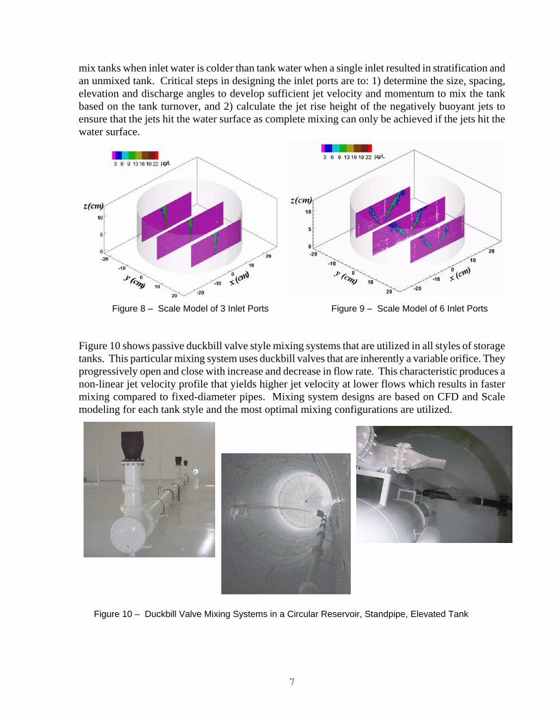
stratification develops. In this case, that is about 40% of the water depth. The water in the bottom 40% has good water quality because it is well-mixed. However, the top 60% of the water volume is not mixed. This is how stratification develops in tanks. With each consecutive fill and draw cycle, the localized water age in the top part of the tank continually increases and water quality problems develop such as loss of residual, nitrification (chloramines), THM spikes, and bacteria regrowth. Note that sampling outside the tank will never indicate there is a water quality problem until, for example, there is a large drawdown, a fire, or a line-break. Even fall turnover, where colder ambient temperatures cool the water in the top of the tank, has also been the cause of poor water quality in the distribution system as the cooling water in the top of the tank falls to the bottom and is drawn out into the distribution system. Note that Equation 1 does not have any limits or variables that account for the effects of different water temperatures. Caution needs to be exercised as this equation will return a fill time required to mix the tank but the tank may not mix depending on the momentum of the inflow, the temperature differential, and the inlet pipe configuration. Stratification can develop in all styles of storage tanks, not just standpipes. Figure 7 shows scale modeling results of a circular reservoir with a bottom inlet filling the tank with colder water (Roberts, et al., 2006). In this case, the jet reaches the surface but falls to the floor as the inlet water is still negatively buoyant. Once the jet hits the floor, all vertical momentum is lost and stratification develops. Note that the outlet pipe, regardless of it’s location along the bottom of the tank, would not prevent stratification from developing in this tank. Therefore, emphasis needs to be placed on designing the piping/mixing system to achieve complete mixing, not just a simple inlet and outlet separation. MULTIPLE INLET JETS The effect of multiple inlet ports on mixing was studied in various tank geometries (Roberts, et al., 2006). Figures 8 and 9 show scale models of tanks with multiple inlet ports. Experiments showed that distributing the inlet thru multiple inlet ports results in significantly faster mixing, up to 50% faster compared to a single inlet pipe. It is analogous to large public swimming pools that have inlet ports spaced 10-20 feet around the perimeter of the pool. The design intent of using multiple inlet ports in pools is for the rapid dispersion of re-chlorinated water, and to eliminate dead zones. In addition to faster mixing, experiments also showed that multiple ports were able to completely
Figure 7 – Scale Model of Circular Reservoir with Colder Inlet Water
7
mix tanks when inlet water is colder than tank water when a single inlet resulted in stratification and an unmixed tank. Critical steps in designing the inlet ports are to: 1) determine the size, spacing, elevation and discharge angles to develop sufficient jet velocity and momentum to mix the tank based on the tank turnover, and 2) calculate the jet rise height of the negatively buoyant jets to ensure that the jets hit the water surface as complete mixing can only be achieved if the jets hit the water surface.
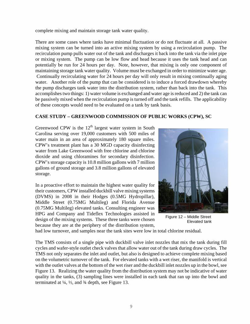
Figure 10 shows passive duckbill valve style mixing systems that are utilized in all styles of storage tanks. This particular mixing system uses duckbill valves that are inherently a variable orifice. They progressively open and close with increase and decrease in flow rate. This characteristic produces a non-linear jet velocity profile that yields higher jet velocity at lower flows which results in faster mixing compared to fixed-diameter pipes. Mixing system designs are based on CFD and Scale modeling for each tank style and the most optimal mixing configurations are utilized.
Figure 8 – Scale Model of 3 Inlet Ports Figure 9 – Scale Model of 6 Inlet Ports
Figure 10 – Duckbill Valve Mixing Systems in a Circular Reservoir, Standpipe, Elevated Tank

8
TANK-SPECIFIC DESIGN Given the many different tank styles and geometries, the inlet/outlet piping or mixing system must be specifically modeled and designed for each tank style. A common design for a circular reservoir, for example, is almost always not a good design for a standpipe. Figure 11 shows CFD and Scale Models of mixing systems for rectangular reservoirs, standpipes, and elevated tanks. The same design process holds for every tank style which is to determine the size, spacing, elevation and discharge angles to develop sufficient velocity to mix the tank based on the tank turnover and to calculate the jet rise height of the negatively buoyant jets to ensure that the jets hit the water surface as complete mixing can only be achieved if the jets hit the water surface.
ACTIVE MIXING As discussed above, properly designed passive mixing systems have been extensively CFD and Scale modeled and utilized for at least ten years and have been proven effective through owner-conducted field sampling to achieve complete mixing, eliminate stratification, and maintain water quality. Storage tanks are designed to exchange water volume (fluctuate levels) and need to exchange water volume to minimize water age. There is already an energy source in distribution systems which is differential pressure when tanks refill. Pumps, and even gravity-driven systems, are designed to get the tanks to high water level, overflow level, plus freeboard. The combination of this inherent energy source and a properly designed passive mixing system has proven to achieve
Figure 11 – CFD and Scale Models for Rectangular Reservoirs, Elevated Tanks and Standpipes
9
Figure 12 – Middle Street Elevated tank
complete mixing and maintain storage tank water quality. There are some cases where tanks have minimal fluctuation or do not fluctuate at all. A passive mixing system can be turned into an active mixing system by using a recirculation pump. The recirculation pump pulls water out of the tank and discharges it back into the tank via the inlet pipe or mixing system. The pump can be low flow and head because it uses the tank head and can potentially be run for 24 hours per day. Note, however, that mixing is only one component of maintaining storage tank water quality. Volume must be exchanged in order to minimize water age. Continually recirculating water for 24 hours per day will only result in mixing continually aging water. Another role of the pump that can be considered is to induce a forced drawdown whereby the pump discharges tank water into the distribution system, rather than back into the tank. This accomplishes two things: 1) water volume is exchanged and water age is reduced and 2) the tank can be passively mixed when the recirculation pump is turned off and the tank refills. The applicability of these concepts would need to be evaluated on a tank by tank basis. CASE STUDY – GREENWOOD COMMISSION OF PUBLIC WORKS (CPW), SC Greenwood CPW is the 12th largest water system in South Carolina serving over 19,000 customers with 500 miles of water main in an area of approximately 180 square miles. CPW’s treatment plant has a 30 MGD capacity disinfecting water from Lake Greenwood with free chlorine and chlorine dioxide and using chloramines for secondary disinfection. CPW’s storage capacity is 10.8 million gallons with 7 million gallons of ground storage and 3.8 million gallons of elevated storage. In a proactive effort to maintain the highest water quality for their customers, CPW installed duckbill valve mixing systems (DVMS) in 2008 in their Hodges (0.5MG Hydropillar), Middle Street (0.75MG Multileg) and Florida Avenue (0.75MG Multileg) elevated tanks. Consulting engineer was HPG and Company and Tideflex Technologies assisted in design of the mixing systems. These three tanks were chosen because they are at the periphery of the distribution system, had low turnover, and samples near the tank sites were low in total chlorine residual. The TMS consists of a single pipe with duckbill valve inlet nozzles that mix the tank during fill cycles and wafer-style outlet check valves that allow water out of the tank during draw cycles. The TMS not only separates the inlet and outlet, but also is designed to achieve complete mixing based on the volumetric turnover of the tank. For elevated tanks with a wet riser, the manifold is vertical with the outlet valves at the bottom of the wet riser and the duckbill inlet nozzles up in the bowl, see Figure 13. Realizing the water quality from the distribution system may not be indicative of water quality in the tanks, (3) sampling lines were installed in each tank that ran up into the bowl and terminated at ¼, ½, and ¾ depth, see Figure 13.

10
Figure 13 – Duckbill Valve Mixing System for Wet Riser Elevated Tanks
Duckbill Valve Inlet Nozzles
Outlet Check Valves

11
CPW collects samples from 3 different depths within each tank once per month on average. CPW targets total residual to be in the 2-3 mg/L range. Figure 14 shows the monthly temperature, total chlorine residual, and pH data for the Florida Street 0.75MG elevated tank from 2009 and 2010. The data shows consistent water quality at the 3 sampling locations throughout the year which confirms complete mixing and consistent water quality within the tank. The Hodges and Middle Street tanks exhibit similar results. CPW reports that, not only is water quality consistent within the tanks, but residuals out in the distribution system near the tanks have improved and the pH is more stable.
Figure 14 – (2009 and 2010) Temperature, Total Chlorine Residual and pH Sampling Data from 0.75MG Elevated Tank Sampling Lines

12
DISCUSSION AND CONCLUSION As a result of extensive CFD and Physical Scale modeling and field monitoring studies in recent years, great insight was gained in identifying the causes of poor mixing, stratification, and the associated water quality problems that develop in water storage tanks. After all, an in-depth understanding of what causes the problems was needed in order to conceptualize, model, and evaluate proposed methods to correct them. Mixing characteristics of storage tanks are now well understood as a result of the modeling and monitoring. The design principles and tools are now available that allow for the proper design of inlet/outlet configurations and mixing systems that achieve complete mixing maintain storage tank water quality. ACKNOWLEDGEMENTS The author would like to acknowledge and thank Mr. David Tuck, Mr. Charles Dunn and the staff at Greenwood CPW for their contributions of photographs, sampling data, and discussions on the CPW treatment plant, distribution system, and water quality. REFERENCES Duer, M.J., (2003). “Use of CFD to Analyze the Effects of Buoyant Inlet Jets on Mixing in
Standpipes.” Proc. 2003 AWWA Annual Conference. Anaheim, CA.
Grayman, W. M., Rossman, L. A., Arnold, C., Deininger, R. A., Smith, C., Smith, J. F., and Schnipke, R. (1999). "Water Quality Modeling of Distribution System Storage Facilities.” AWWA Research Foundation, Denver, CO.
Rossman, L. A., and Grayman, W. M. (1999). "Scale-model studies of mixing in drinking water storage tanks." Journal of Environmental Engineering, ASCE, 125(8), 755-761.
Roberts, P. J. W., Tian, X., and Sotiropoulos, F., and Duer, M. (2006). “Physical Modeling of Mixing in Water Storage Tanks Final Report,” School of Civil Engineering, Georgia Institute of Technology, Prepared for AWWA Research Foundation.
Related Documents