Welcome message from author
This document is posted to help you gain knowledge. Please leave a comment to let me know what you think about it! Share it to your friends and learn new things together.
Transcript


How To Use This Catalog
RSVP Tooling, Inc. • Toll Free 888-289-7787 • Direct 815-725-3310 • Fax 815-725-3391 • Email [email protected] • www.rsvptooling.com
Clickable & Touch Links Within each page we have included a wide range of linksthat can be click when viewed on a computer or touchedon a smart device (phones and pads).
The side tabs to the left when click will return you to thesection index.
On the master index and section indexes the line items alsocontain links to the indicated pages.
Tangential Index ........................................................70Attachments ...............................................................71Thread Rolls & Setting Gauges................................72 Design of Rolls ...........................................................73RT10 - RT20 - RT30 Overview & Components74 - 75 Tangential Charts ...............................................76 - 77
Click this icon to follow and like RSVP Toolingon FaceBook. Get the most up-to-date informa-tion on products, training, videos and productsfor your smart devices.
Click this icon to follow our short RSVP tweets.Quick tips and helpful links to increase yourthreading quality and productivity.
Click this icon to expand your network of professional contacts.
Click this icon to visit our video channel. When this icon is next to a product you can directly link to a demonstration video.
Click this icon to quickly access our extensive knowledge base within the RSVP Tooling website.
Click this icon to return to the main index of this catalog.
Click this icon to return to the section index for that product or page.
Icon Links
Welcome To The RSVP Tooling Interactive CatalogDownloading this catalog to a smart device
This catalog can be viewedon smart devices such asphones and pads. Most freePDF viewers will allow youto flip from page to page.
However, if you would liketo take advantage of thebuilt in interactive featuresyou will need to downloadan app.
We have reviewed many apps and have found that ezPDFReader seems to work the best on both the Apple andDroid product lines. It is available in two forms - one forthe pads and one for the phones.
Start by going to your apps downloadcenter on your device. Search for “ezPDFReader” and look for the above icon.Purchase the app that matches your device.Download and activate the app.
Follow the instructions to download a file to the app. Select “URL Download” and enter the following -“http://www.rsvptooling.com/RSVPcatalog.pdf”. Oncethe catalog is loaded you can start using the interactive features.
RSVP Tooling, Inc. • Toll Free 888-289-7787 • Direct 815-725-3310 • Fax 815-725-3391 • Email [email protected] • www.rsvptooling.com
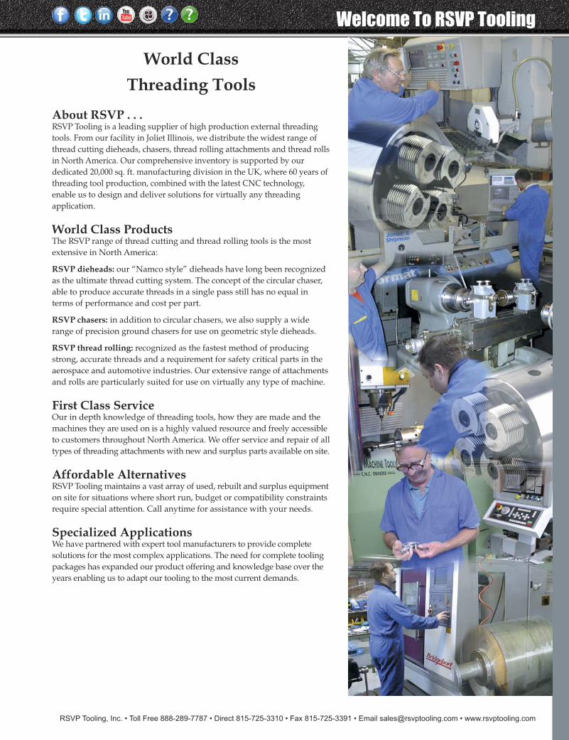
World ClassThreading Tools
About RSVP . . .RSVP Tooling is a leading supplier of high production external threadingtools. From our facility in Joliet Illinois, we distribute the widest range ofthread cutting dieheads, chasers, thread rolling attachments and thread rollsin North America. Our comprehensive inventory is supported by ourdedicated 20,000 sq. ft. manufacturing division in the UK, where 60 years ofthreading tool production, combined with the latest CNC technology,enable us to design and deliver solutions for virtually any threadingapplication.
World Class ProductsThe RSVP range of thread cutting and thread rolling tools is the mostextensive in North America:
RSVP dieheads: our “Namco style” dieheads have long been recognizedas the ultimate thread cutting system. The concept of the circular chaser,able to produce accurate threads in a single pass still has no equal interms of performance and cost per part.
RSVP chasers: in addition to circular chasers, we also supply a widerange of precision ground chasers for use on geometric style dieheads.
RSVP thread rolling: recognized as the fastest method of producingstrong, accurate threads and a requirement for safety critical parts in theaerospace and automotive industries. Our extensive range of attachmentsand rolls are particularly suited for use on virtually any type of machine.
First Class ServiceOur in depth knowledge of threading tools, how they are made and themachines they are used on is a highly valued resource and freely accessibleto customers throughout North America. We offer service and repair of alltypes of threading attachments with new and surplus parts available on site.
Affordable AlternativesRSVP Tooling maintains a vast array of used, rebuilt and surplus equipmenton site for situations where short run, budget or compatibility constraintsrequire special attention. Call anytime for assistance with your needs.
Specialized ApplicationsWe have partnered with expert tool manufacturers to provide completesolutions for the most complex applications. The need for complete toolingpackages has expanded our product offering and knowledge base over theyears enabling us to adapt our tooling to the most current demands.
Welcome To RSVP Tooling
Catalog Index
RSVP Tooling, Inc. • Toll Free 888-289-7787 • Direct 815-725-3310 • Fax 815-725-3391 • Email [email protected] • www.rsvptooling.com
2
AxialFor producing long threads, or threads without run-out restriction,RSVP axial rolling heads are the ideal selection. Axial heads feed onfrom the end of the part and require one revolution of the spindle foreach pitch of thread to be produced. Controlled forward axial motion,either by cam or CNC feed, are recommended although manuallyoperated lathes can also give excellent results. RSVP axial headsare self opening and require an external closing mechanism to resetthem. Right hand rolling heads are required for rolling right handthreads and the spindle direction must also be right hand. Lefthand threads require corresponding heads and spindle rotation.
Circular Chaser Index . . . . . . . . . . . . . . . . . . . . . . . . .4Circular Chasers Advantages . . . . . . . . . . . . . . . . . .5DR - Overview & Components . . . . . . . . . . . . . . . .6DRF - Overview & Components . . . . . . . . . . . . . . .7DRD - Overview & Components . . . . . . . . . . . . . . .8DS - Overview & Components . . . . . . . . . . . . . . . . .9DSF - Overview & Components . . . . . . . . . . . . . . .10DBS - Overview & Components . . . . . . . . . . . . . . .11DRSA - Overview & Components . . . . . . . . . . . . .12DRSA-Biltz - Overview & Components . . . . . . . . .13DRFSA - Overview & Components . . . . . . . . . . . .14Custom Circular Chaser Heads . . . . . . . . . . . . . . .15Special Circular Chaser Services . . . . . . . . . . . . . .15Oversized Circular Chaser Heads . . . . . . . . . . . . .15Stock Modular Shanks . . . . . . . . . . . . . . . . . . .16 - 18DR61 Chaser Screws Component Parts . . . . . . . . .19 Serrated Bushing Chart DR63 . . . . . . . . . . . . . . . . .19 Grinding Accessories . . . . . . . . . . . . . . . . . . . . . . . .20Circular Chasers & Blocks Charts . . . . . . . . . .21 - 22How To Order Circular Chasers . . . . . . . . . . . . . . .22
Geometric Chaser Index ...........................................23D-Style - Overview & Components.................23 - 24DJ - Overview & Components ................................25SAMN - Overview & Components ........................26SAMAN - Overview & Components......................27Geometric Chaser Specs & Terms ...................28 - 29How To Order Geometric Chasers .........................29
Axial Thread Rolling Index / How To Order ........30RSVP Thread Rolling System Advantages..............31Thread Rolling Introduction ....................................32Applications ................................................................33A0 - Overview & Components ................................34A001 - Overview & Components ............................35A01 - Overview & Components ..............................36A1 - Overview & Components ................................37A12 - Overview & Components ...............................38A2 - Overview & Components .................................39 A23 - Overview & Components ..............................40A233400 - Overview & Components .......................41 A3 - Overview & Components .................................42 A34 - Overview & Components ..............................43 A4 - Overview & Components ................................44 A45 - Overview & Components ..............................45 A5 - Overview & Components ................................46 A56 - Overview & Components ..............................47Operation..............................................................48 - 50Problem Solving .........................................................51Lead Angles..........................................................52 - 54Recommended Blank Diameters .......................55 - 57Rolling Speeds ............................................................58
Circular Chaser System The Circular Chaser shape allows for the chaser to beground through a full 270 degrees, which makes the circularstyle chaser by far, the system with the longest tool life overall other threading systems. The circular shape of the cutterpermits only enough rubbing action immediately behind thecutting edge to ensure proper lead control. This eliminatesexcessive rubbing and assures smoother threads and longerchaser life. In addition, the chasers body mass and externalmounting provides a faster dissipation of heat away fromthe work, frees chips for faster cutting speeds and allows theability to cut up close to the shoulder of a part. RSVP Tooling’sexclusive modular shank dieheads provide the ability tochoose the specific shank adapter suitable for your machineor for use in multiple machines. The shank adapter optionalso minimizes cost associated with shank replacement dueto common wear and use.
Geometric Geometric or insert style chaser heads provide an affordable alternative to other systems when short run jobs and intermittentuse are necessary. RSVP Tooling offers several variations tochoose from that can be tailored to virtually any application.Standard stationary “self-opening” as well as solid adjustableand acorn die replacement models are offered for use in almostany type of machine. Any of the options available can also bemade specific to your requirements.
RSVP Tooling, Inc. • Toll Free 888-289-7787 • Direct 815-725-3310 • Fax 815-725-3391 • Email [email protected] • www.rsvptooling.com
3
Zeus Knurling & Marking ToolsRSVP Tooling is the exclusive North American distributor forZeus Knurling and Marking tools. German engineering and precision manufacturing qualify these tools as the best high precision option available. Our partnership affords unbeatabledesign support to meet any requirement.
For further information please ask for our knurling or markingspecific catalogs or go to www.hommel-keller.com to view themost current information available.
Catalog Index
Tangential Thread Rolling Index..............................66Attachments ................................................................67Thread Rolls & Setting Gauges.................................68 Design of Rolls ............................................................69RT10 - Overview & Components .............................70RT20 - Overview & Components .............................71RT30 - Overview & Components .............................72 Tangential Thread Roll Charts ..................................73 Custome Tangential Thread Rolls ............................74
RS Spline Rolling Head.............................................75
Zeus Cut Knurling Tools ..........................................76Zeus Form Knurling Tools .......................................77Zeus Marking Tools ..................................................78
Specialty ToolsRSVP Tooling has partnered with precision tool holdingmanufacturers to provide complete set up solutions to adaptour tooling to any application.
Please contact us with your needs and we can use our manyresources to provide an economic and custom engineeredsolution for you.
Baublies Precision Roller and Diamond Burnishing tools .......................................79Specialty Toolholders ................................................80
Radial Thread Rolling Index ...................................59Radial Thread Rolling Operation ...........................60RE-8 - Overview & Components.............................61RE-10 - Overview & Components...........................62RE-13 - Overview & Components...........................63RE-16 - Overview & Components...........................64RE-23 - Overview & Components...........................65
RadialRSVP Radial rolling heads offer an ideal solution for producingvery short threads with tight runout, rolling close to a shoulderor into an undercut. Due to the 3-roll action of the radial system,the component is well supported during the rolling process,even when threading the ends of long shafts. Since the rollingaction is completed within one revolution of the rolls, cycletimes are extremely short and in most cases, under 0.5 seconds.Radial rolling heads are automatically reset after each threadingpass, but are normally actuated by means of the external triplever on stationary heads, or an internal push rod on rotatingheads.
TangentialThis system is used mainly on bar lathes for rolling short threadsclose to the shoulder or behind the shoulder. The tangentialattachment is fitted to the machine cross slide and undercontrolled feed, forces the rolls tangentially over the rotatingpart up to its center line. Unlike axial heads, tangential rollingheads do not have the ability to traverse along the part to producea thread. Therefore thread length is limited to the maximumthread roll width for the head used. Tangential attachments canroll both right and left hand threads with spindle rotation ineither direction. Only the roll design is changed.
SplineWe offer job specific synchronized spline rolling heads to suitnearly any application.
The 3 roll design is offered in two styles engineered to meet yourspecification. A spring loaded retractable style for shorter partsand an external three roll synchronized design for longer partsare available.
Our Spline Rolling heads are the industry standard for accuraterepeatability and reliable performance for virtually any size partand particularly useful for large run jobs.
Circular Chasers
RSVP Tooling, Inc. • Toll Free 888-289-7787 • Direct 815-725-3310 • Fax 815-725-3391 • Email [email protected] • www.rsvptooling.com
4
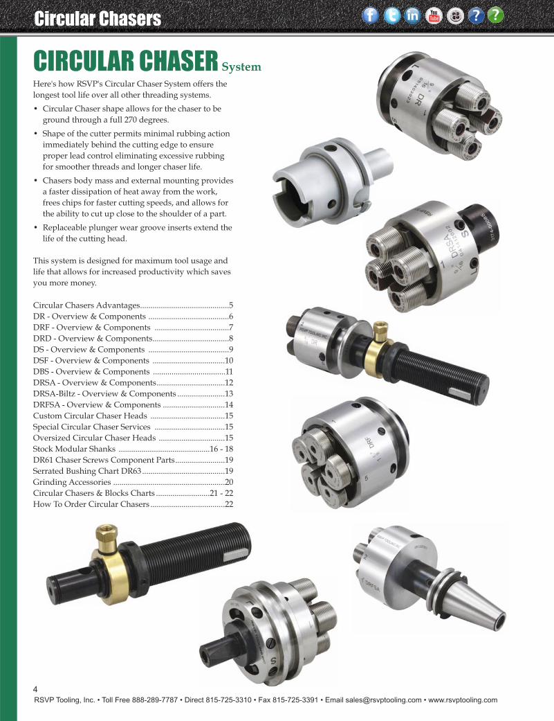
Here's how RSVP's Circular Chaser System offers thelongest tool life over all other threading systems.
• Circular Chaser shape allows for the chaser to beground through a full 270 degrees.
• Shape of the cutter permits minimal rubbing actionimmediately behind the cutting edge to ensureproper lead control eliminating excessive rubbingfor smoother threads and longer chaser life.
• Chasers body mass and external mounting providesa faster dissipation of heat away from the work,frees chips for faster cutting speeds, and allows forthe ability to cut up close to the shoulder of a part.
• Replaceable plunger wear groove inserts extend thelife of the cutting head.
This system is designed for maximum tool usage andlife that allows for increased productivity which savesyou more money.
CIRCULAR CHASER System
Circular Chasers Advantages...........................................5DR - Overview & Components .......................................6DRF - Overview & Components ....................................7DRD - Overview & Components.....................................8DS - Overview & Components .......................................9DSF - Overview & Components ...................................10DBS - Overview & Components ...................................11DRSA - Overview & Components.................................12DRSA-Biltz - Overview & Components .......................13DRFSA - Overview & Components ..............................14Custom Circular Chaser Heads ....................................15Special Circular Chaser Services ..................................15Oversized Circular Chaser Heads ................................15Stock Modular Shanks ............................................16 - 18DR61 Chaser Screws Component Parts........................19 Serrated Bushing Chart DR63........................................19 Grinding Accessories ......................................................20Circular Chasers & Blocks Charts ..........................21 - 22How To Order Circular Chasers ....................................22
RSVP Tooling, Inc. • Toll Free 888-289-7787 • Direct 815-725-3310 • Fax 815-725-3391 • Email [email protected] • www.rsvptooling.com
5
Circular Chasers
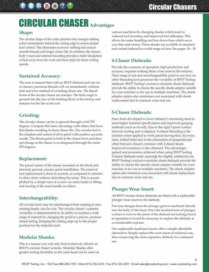
Shape:The circular shape of the cutter permits only enough rubbingaction immediately behind the cutting edge to ensure properlead control. This eliminates excessive rubbing and assuressmooth threads and longer chaser life. In addition, the chasersbody’s mass and external mounting provides a faster dissipationof heat away from the work and frees chips for faster cuttingspeeds.
Sustained Accuracy:The user is assured that with an RSVP diehead and one setof chasers, precision threads will cut immediately withouttrial and error method of switching chaser sets. The threadforms of the circular chaser are annular. The helix angle isground into the face of the holding block at the factory andremains for the life of the tool.
Grinding:The circular chaser can be re-ground through a full 270degrees. Compare this basic advantage with others that havethin blades resulting in short chaser life. The circular tool isthe simplest and easiest of all to grind with positive accurateresults. The throat grind is built in the chaser form and doesnot change as the chaser is re-sharpened through the entire270 degrees.
Replacement:The preset nature of the chaser mounted on the block andprecisely ground, assures quick installation. The removaland replacement is done in seconds, as compared to minutesin other styles without disturbing the setup. This is accom-plished by a simple turn of a screw on some heads or liftingand turning of the reset handle on others.
Interchangeability:All circular tools may be interchanged from rotating to non-rotating heads, size for size. The circular chaser’s extremeversatility is demonstrated by its ability to machine a widerange of material by changing the grind to a precise, predeter-mined setting, bringing the cutting edge up to the properposition for the material used.
Modular Shanks:This is a feature you will only find exclusively offered onRSVP's circular chaser systems. Modular Shanks offergreater tooling flexibility as the same head can be used on
various machines by changing shanks which leads toreduced tool inventory and improved tool utilization. Thisallows for easier handling and less down time which savesyou time and money. These shanks are available in standardand coolant induced in a wide range of sizes. See pages: 16 - 18
4-Chaser Dieheads:Provide the economy of operation, high production andaccuracy required making them a true asset to the industry.Their range of size and interchangeability point to one fact; noother threading tool possesses the versatility of RSVP Toolingdieheads. RSVP Tooling’s exclusive modular shank dieheadsprovide the ability to choose the specific shank adapter suitablefor your machine or for use in multiple machines. The shankadapter option also minimizes cost associated with shankreplacement due to common wear and use.
5-Chaser Dieheads:Have been developed to cover industry’s increasing need tomeet higher material specifications and improved gaugingmethods (such as tri-roll). Due to the rigid 5-point contactbetween tooling and workpiece, 5-chaser threading is thesolution when applied to work pieces having flats, keyways,slots, drilled holes due to the elimination of perpendicularoffset between chasers common with 4 chaser heads.Improved roundness is also obtained. The advantagesgained and economics achieved when using RSVP tooling5-chaser dieheads easily outweigh the slightly additional cost.RSVP Tooling’s exclusive modular shank dieheads provide theability to choose the specific shank adapter suitable for yourmachine or for use in multiple machines. The shank adapteroption also minimizes cost associated with shank replacementdue to common wear and use.
Plunger Wear Insert:All RSVP circular chaser dieheads are fitted with a replaceableplunger wear insert in the diebody.
Previous designs have the plunger groove machined directlyinto the body of the head. Once the localized area of plungercontact is worn to the point of the diehead not locking closedin operation it would be necessary to replace the diebody ata considerable expense.
Our replaceable hardened inserts offer a simple affordablealternative. Simply replace the worn insert at minimal cost,thus conserving the more expensive diebody for continueduse.
CIRCULAR CHASER Advantages
6
Circular Chasers
RSVP Tooling, Inc. • Toll Free 888-289-7787 • Direct 815-725-3310 • Fax 815-725-3391 • Email [email protected] • www.rsvptooling.com
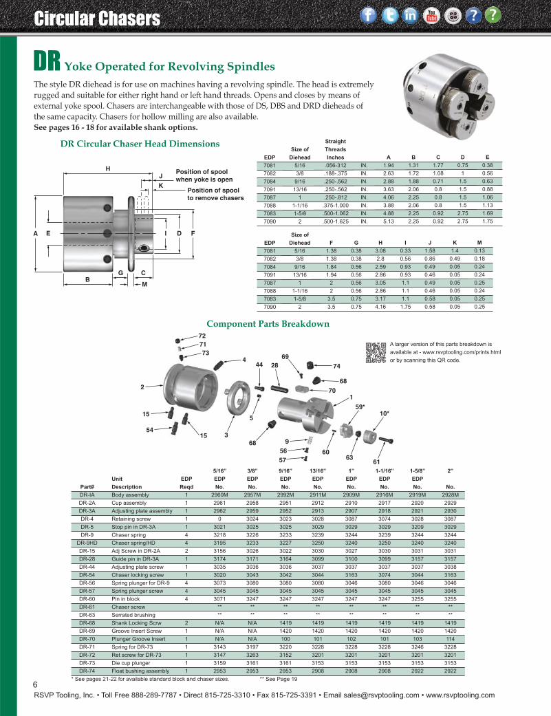
DR Yoke Operated for Revolving SpindlesThe style DR diehead is for use on machines having a revolving spindle. The head is extremelyrugged and suitable for either right hand or left hand threads. Opens and closes by means of external yoke spool. Chasers are interchangeable with those of DS, DBS and DRD dieheads ofthe same capacity. Chasers for hollow milling are also available.See pages 16 - 18 for available shank options.
72
71
734
2
59*
63
10*
61
3
5
44 28
70
68
6056
915
15
54
69
74
68
1
57
EA I D F
B
H
K
JPosition of spool
when yoke is open
Position of spool
to remove chasers
G C
M
A larger version of this parts breakdown is
available at - www.rsvptooling.com/prints.html
or by scanning this QR code.
5/16” 3/8” 9/16” 13/16” 1” 1-1/16” 1-5/8” 2”
Unit EDP EDP EDP EDP EDP EDP EDP EDP
Part# Description Reqd No. No. No. No. No. No. No. No.
DR-IA Body assembly 1 2960M 2957M 2992M 2911M 2909M 2916M 2919M 2928M
DR-2A Cup assembly 1 2961 2958 2951 2912 2910 2917 2920 2929
DR-3A Adjusting plate assembly 1 2962 2959 2952 2913 2907 2918 2921 2930
DR-4 Retaining screw 1 0 3024 3023 3028 3087 3074 3028 3087
DR-5 Stop pin in DR-3A 1 3021 3025 3025 3029 3029 3029 3209 3029
DR-9 Chaser spring 4 3218 3226 3233 3239 3244 3239 3244 3244
DR-9HD Chaser spring/HD 4 3195 3233 3227 3250 3240 3250 3240 3240
DR-15 Adj Screw in DR-2A 2 3156 3026 3022 3030 3027 3030 3031 3031
DR-28 Guide pin in DR-3A 1 3174 3171 3164 3099 3100 3099 3157 3157
DR-44 Adjusting plate screw 1 3035 3036 3036 3037 3037 3037 3037 3038
DR-54 Chaser locking screw 1 3020 3043 3042 3044 3163 3074 3044 3163
DR-56 Spring plunger for DR-9 4 3073 3080 3080 3080 3046 3080 3046 3046
DR-57 Spring plunger screw 4 3045 3045 3045 3045 3045 3045 3045 3045
DR-60 Pin in block 4 3071 3247 3247 3247 3247 3247 3255 3255
DR-61 Chaser screw ** ** ** ** ** ** ** **
DR-63 Serrated brushing ** ** ** ** ** ** ** **
DR-68 Shank Locking Scrw 2 N/A N/A 1419 1419 1419 1419 1419 1419
DR-69 Groove Insert Screw 1 N/A N/A 1420 1420 1420 1420 1420 1420
DR-70 Plunger Groove Insert 1 N/A N/A 100 101 102 101 103 114
DR-71 Spring for DR-73 1 3143 3197 3220 3228 3228 3228 3246 3228
DR-72 Ret screw for DR-73 1 3147 3263 3152 3201 3201 3201 3201 3201
DR-73 Die cup plunger 1 3159 3161 3161 3153 3153 3153 3153 3153
DR-74 Float bushing assembly 1 2953 2953 2953 2908 2908 2908 2922 2922
* See pages 21-22 for available standard block and chaser sizes. ** See Page 19
DR Circular Chaser Head Dimensions Straight
Size of Threads
EDP Diehead Inches A B C D E
7081 5/16 .056-312 IN. 1.94 1.31 1.77 0.75 0.38
7082 3/8 .188-.375 IN. 2.63 1.72 1.08 1 0.56
7084 9/16 .250-.562 IN. 2.88 1.88 0.71 1.5 0.63
7091 13/16 .250-.562 IN. 3.63 2.06 0.8 1.5 0.88
7087 1 .250-.812 IN. 4.06 2.25 0.8 1.5 1.06
7088 1-1/16 .375-1.000 IN. 3.88 2.06 0.8 1.5 1.13
7083 1-5/8 .500-1.062 IN. 4.88 2.25 0.92 2.75 1.69
7090 2 .500-1.625 IN. 5.13 2.25 0.92 2.75 1.75
Size of
EDP Diehead F G H I J K M
7081 5/16 1.38 0.38 3.08 0.33 1.58 1.4 0.13
7082 3/8 1.38 0.38 2.8 0.56 0.86 0.49 0.18
7084 9/16 1.84 0.56 2.59 0.93 0.49 0.05 0.24
7091 13/16 1.94 0.56 2.86 0.93 0.46 0.05 0.24
7087 1 2 0.56 3.05 1.1 0.49 0.05 0.25
7088 1-1/16 2 0.56 2.86 1.1 0.46 0.05 0.24
7083 1-5/8 3.5 0.75 3.17 1.1 0.58 0.05 0.25
7090 2 3.5 0.75 4.16 1.75 0.58 0.05 0.25
Component Parts Breakdown
7
RSVP Tooling, Inc. • Toll Free 888-289-7787 • Direct 815-725-3310 • Fax 815-725-3391 • Email [email protected] • www.rsvptooling.com
Circular Chasers
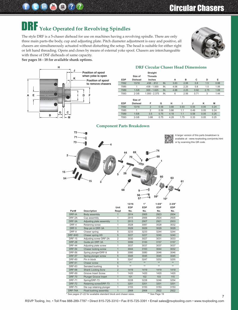
DRF Yoke Operated for Revolving SpindlesThe style DRF is a 5-chaser diehead for use on machines having a revolving spindle. There are onlythree main parts-the body, cup and adjusting plate. Pitch diameter adjustment is easy and positive, allchasers are simultaneously actuated without disturbing the setup. The head is suitable for either rightor left hand threading. Opens and closes by means of external yoke spool. Chasers are interchangeablewith those of DSF dieheads of same capacity.See pages 16 - 18 for available shank options.
5 28
68
3
59*10*
60 63
61
1
746944
6870
473
71
72
2
15
5415
9
5657
EA I D F
B
H
K
JPosition of spool
when yoke is open
Position of spool
to remove chasers
G C
M
A larger version of this parts breakdown is
available at - www.rsvptooling.com/prints.html
or by scanning this QR code.
13/16 1” 1-5/8” 2-3/8”
Unit EDP EDP EDP EDP
Part# Description Reqd No. No. No. No.
DRF-IA Body assembly 1 2914 2905 2923 2934
DRF-2A Cup assembly 1 2915 2906 2924 2935
DRF-3A Adjusting plate assembly 1 2913 2907 2921 2933
DRF-4 Retaining screw 1 3028 3087 3028 3032
DRF-5 Stop pin in DRF-3A 1 3029 3029 3029 3029
DRF-9 Chaser spring 5 3233 3233 3244 3244
DRF-9HD Chaser spring HD 5 3227 3227 3240 3240
DRF-15 Adjusting screw DRF-2A 2 3030 3027 3031 3033
DRF-28 Guide pin DRF-3A 1 3099 3100 3157 3157
DRF-44 Adjusting plate screw 1 3037 3037 3037 3037
DRF-54 Chaser locking screw 1 3044 3163 3044 3032
DRF-56 Spring plunger/DRF-9 5 3080 3080 3046 3046
DRF-57 Spring plunger screw 5 3045 3045 3045 3045
DRF-60 Pin in block 5 3247 3247 3252 3255
DRF-61 Chaser screw 5 ** ** ** **
DRF-63 Serrated bushing 5 ** ** ** **
DRF-68 Shank Locking Scrw 2 1419 1419 1419 1419
DRF-69 Groove Insert Screw 1 1420 1420 1420 1420
DRF-70 Plunger Groove Insert 1 101 102 103 115
DRF-71 Spring/DRF-73 1 3228 3228 3246 3254
DRF-72 Retaining screw/DRF-73 1 3201 3201 3201 3201
DRF-73 Die cup retaining plunger 1 3153 3153 3153 3153
DRF-74A Float bushing assembly 1 2908 2908 2922 2922
* See pages 21-22 for available standard block and chaser sizes. ** See Page 19
Component Parts Breakdown
Straight
Size of Threads
EDP Diehead Inches A B C D E
7092 13/16 .438 - .812 IN. 3.63 2.06 0.8 1.5 0.88
7085 1 .438 - 1.000 IN. 4.06 2.25 0.8 1.5 1.06
7089 1-5/8 .500 - 1.625 IN. 4.88 2.25 0.92 2.75 1.69
7093 2-3/8 1.000 - 2.375 IN. 6 2.56 0.71 3 1.44
Size of
EDP Diehead F G H I J K M
7092 13/16 2 0.56 3.66 0.93 0.55 0.05 0.24
7085 1 2 0.56 3.86 1.1 0.49 0.05 0.24
7089 1-5/8 3.5 0.75 4.18 1.1 0.58 0.05 0.25
7093 2-3/8 3.88 0.75 4.28 1.75 0.33 0.05 0.25
DRF Circular Chaser Head Dimensions
8
Circular Chasers
RSVP Tooling, Inc. • Toll Free 888-289-7787 • Direct 815-725-3310 • Fax 815-725-3391 • Email [email protected] • www.rsvptooling.com
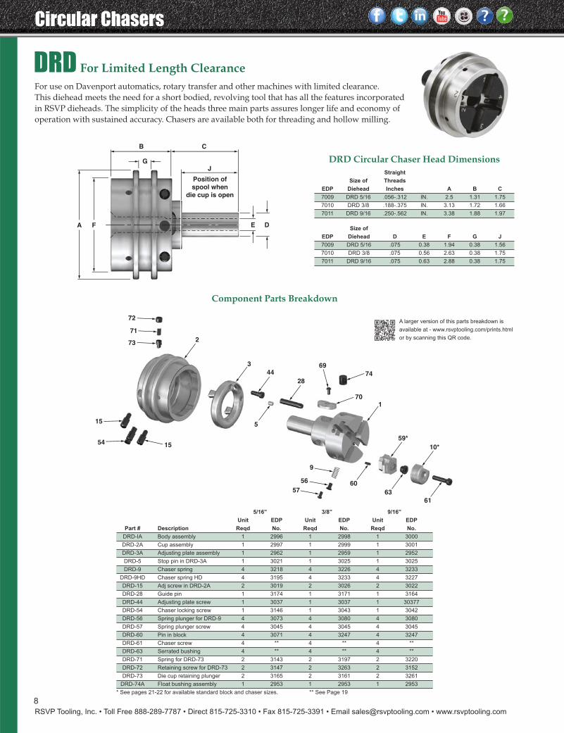
DRD For Limited Length ClearanceFor use on Davenport automatics, rotary transfer and other machines with limited clearance. This diehead meets the need for a short bodied, revolving tool that has all the features incorporatedin RSVP dieheads. The simplicity of the heads three main parts assures longer life and economy ofoperation with sustained accuracy. Chasers are available both for threading and hollow milling.
72
71
73
54
15
2
9
61
63
60
5
59*
10*
1
74
70
69
28
44
3
15
57
56
JG
A F E D
CB
Position of
spool when
die cup is open
A larger version of this parts breakdown is
available at - www.rsvptooling.com/prints.html
or by scanning this QR code.
5/16” 3/8” 9/16”
Unit EDP Unit EDP Unit EDP
Part # Description Reqd No. Reqd No. Reqd No.
DRD-IA Body assembly 1 2996 1 2998 1 3000
DRD-2A Cup assembly 1 2997 1 2999 1 3001
DRD-3A Adjusting plate assembly 1 2962 1 2959 1 2952
DRD-5 Stop pin in DRD-3A 1 3021 1 3025 1 3025
DRD-9 Chaser spring 4 3218 4 3226 4 3233
DRD-9HD Chaser spring HD 4 3195 4 3233 4 3227
DRD-15 Adj screw in DRD-2A 2 3019 2 3026 2 3022
DRD-28 Guide pin 1 3174 1 3171 1 3164
DRD-44 Adjusting plate screw 1 3037 1 3037 1 30377
DRD-54 Chaser locking screw 1 3146 1 3043 1 3042
DRD-56 Spring plunger for DRD-9 4 3073 4 3080 4 3080
DRD-57 Spring plunger screw 4 3045 4 3045 4 3045
DRD-60 Pin in block 4 3071 4 3247 4 3247
DRD-61 Chaser screw 4 ** 4 ** 4 **
DRD-63 Serrated bushing 4 ** 4 ** 4 **
DRD-71 Spring for DRD-73 2 3143 2 3197 2 3220
DRD-72 Retaining screw for DRD-73 2 3147 2 3263 2 3152
DRD-73 Die cup retaining plunger 2 3165 2 3161 2 3261
DRD-74A Float bushing assembly 1 2953 1 2953 1 2953
* See pages 21-22 for available standard block and chaser sizes. ** See Page 19
Component Parts Breakdown
DRD Circular Chaser Head DimensionsStraight
Size of Threads
EDP Diehead Inches A B C
7009 DRD 5/16 .056-.312 IN. 2.5 1.31 1.75
7010 DRD 3/8 .188-.375 IN. 3.13 1.72 1.66
7011 DRD 9/16 .250-.562 IN. 3.38 1.88 1.97
Size of
EDP Diehead D E F G J
7009 DRD 5/16 .075 0.38 1.94 0.38 1.56
7010 DRD 3/8 .075 0.56 2.63 0.38 1.75
7011 DRD 9/16 .075 0.63 2.88 0.38 1.75
9
RSVP Tooling, Inc. • Toll Free 888-289-7787 • Direct 815-725-3310 • Fax 815-725-3391 • Email [email protected] • www.rsvptooling.com
Circular Chasers
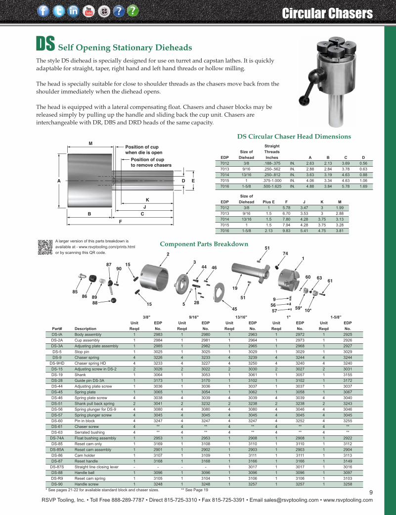
DS Self Opening Stationary DieheadsThe style DS diehead is specially designed for use on turret and capstan lathes. It is quickly adaptable for straight, taper, right hand and left hand threads or hollow milling.
The head is specially suitable for close to shoulder threads as the chasers move back from the shoulder immediately when the diehead opens.
The head is equipped with a lateral compensating float. Chasers and chaser blocks may be released simply by pulling up the handle and sliding back the cup unit. Chasers are interchangeable with DR, DBS and DRD heads of the same capacity.
19
51285
9
56
57
8586 89
9087
88 15
15
60
59*10*
174
51
45
46443
2
6361
A D E
K
M
F
B C
J
Position of cup
to remove chasers
Position of cup
when die is open
3/8" 9/16" 13/16" 1" 1-5/8”
Unit EDP Unit EDP Unit EDP Unit EDP Unit EDP
Part# Description Reqd No. Reqd No. Reqd No. Reqd No. Reqd No.
DS-IA Body assembly 1 2983 1 2980 1 2963 1 2972 1 2925
DS-2A Cup assembly 1 2984 1 2981 1 2964 1 2973 1 2926
DS-3A Adjusting plate assembly 1 2985 1 2982 1 2965 1 2968 1 2927
DS-5 Stop pin 1 3025 1 3025 1 3029 1 3029 1 3029
DS-9 Chaser spring 4 3226 4 3233 4 3239 4 3244 4 3244
DS-9HD Chaser spring HD 4 3233 4 3227 4 3250 4 3240 4 3240
DS-15 Adjusting screw in DS-2 2 3026 2 3022 2 3030 2 3027 2 3031
DS-19 Shank 1 3064 1 3053 1 3061 1 3057 1 3155
DS-28 Guide pin DS-3A 1 3173 1 3170 1 3102 1 3102 1 3172
DS-44 Adjusting plate screw 1 3036 1 3036 1 3037 1 3037 1 3037
DS-45 Spring plate 1 3065 1 3054 1 3062 1 3058 1 3067
DS-46 Spring plate screw 4 3038 4 3039 4 3039 4 3039 4 3040
DS-51 Shank pull back spring 2 3041 2 3232 2 3238 2 3238 2 3243
DS-56 Spring plunger for DS-9 4 3080 4 3080 4 3080 4 3046 4 3046
DS-57 Spring plunger screw 4 3045 4 3045 4 3045 4 3045 4 3045
DS-60 Pin in block 4 3247 4 3247 4 3247 4 3252 4 3255
DS-61 Chaser screw 4 ** 4 ** 4 ** 4 ** 4 **
DS-63 Serrated bushing 4 ** 4 ** 4 ** 4 ** 4 **
DS-74A Float bushing assembly 1 2953 1 2953 1 2908 1 2908 1 2922
DS-85 Reset cam only 1 3169 1 3108 1 3110 1 3110 1 3112
DS-85A Reset cam assembly 1 2901 1 2902 1 2903 1 2903 1 2904
DS-86 Cam holder 1 3107 1 3109 1 3111 1 3111 1 3113
DS-87 Reset handle 1 3168 1 3168 1 3166 1 3166 1 3149
DS-87S Straight line closing lever - - - - 1 3017 1 3017 1 3016
DS-88 Handle ball 1 3096 1 3096 1 3096 1 3096 1 3097
DS-R9 Reset cam spring 1 3105 1 3104 1 3106 1 3106 1 3103
DS-90 Handle screw 1 3248 1 3248 1 3257 1 3257 1 3258
* See pages 21-22 for available standard block and chaser sizes. ** See Page 19
Component Parts Breakdown
Straight
Size of Threads
EDP Diehead Inches A B C D
7012 3/8 .188-.375 IN. 2.63 2.13 3.69 0.56
7013 9/16 .250-.562 IN. 2.88 2.84 3.78 0.63
7014 13/16 .250-.812 IN. 3.63 3.19 4.63 0.88
7015 1 .375-1.000 IN. 4.06 3.34 4.63 1.06
7016 1-5/8 .500-1.625 IN. 4.88 3.84 5.78 1.69
Size of
EDP Diehead Plus E F J K M
7012 3/8 1 5.78 3.47 3 1.99
7013 9/16 1.5 6.70 3.53 3 2.88
7014 13/16 1.5 7.80 4.28 3.75 3.13
7015 1 1.5 7.94 4.28 3.75 3.28
7016 1-5/8 2.13 9.83 5.41 4.75 3.81
DS Circular Chaser Head Dimensions
A larger version of this parts breakdown is
available at - www.rsvptooling.com/prints.html
or by scanning this QR code.
10
Circular Chasers
RSVP Tooling, Inc. • Toll Free 888-289-7787 • Direct 815-725-3310 • Fax 815-725-3391 • Email [email protected] • www.rsvptooling.com
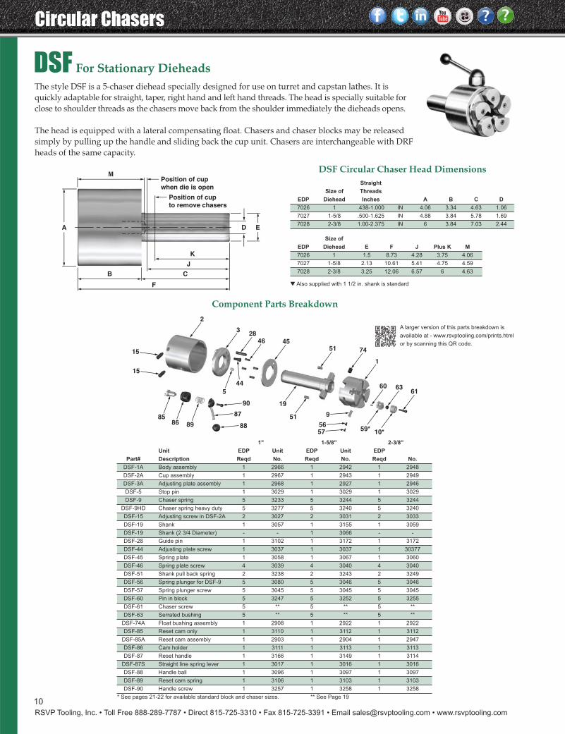
DSF For Stationary DieheadsThe style DSF is a 5-chaser diehead specially designed for use on turret and capstan lathes. It isquickly adaptable for straight, taper, right hand and left hand threads. The head is specially suitable forclose to shoulder threads as the chasers move back from the shoulder immediately the dieheads opens.
The head is equipped with a lateral compensating float. Chasers and chaser blocks may be releasedsimply by pulling up the handle and sliding back the cup unit. Chasers are interchangeable with DRFheads of the same capacity.
19
51 9
5657
15
15
858986
88
87
90
60
59*10*
1
74
28
514546
44
5
3
2
6361
A D E
K
M
F
B C
J
Position of cup
to remove chasers
Position of cup
when die is open
A larger version of this parts breakdown is
available at - www.rsvptooling.com/prints.html
or by scanning this QR code.
1" 1-5/8" 2-3/8"
Unit EDP Unit EDP Unit EDP
Part# Description Reqd No. Reqd No. Reqd No.
DSF-1A Body assembly 1 2966 1 2942 1 2948
DSF-2A Cup assembly 1 2967 1 2943 1 2949
DSF-3A Adjusting plate assembly 1 2968 1 2927 1 2946
DSF-5 Stop pin 1 3029 1 3029 1 3029
DSF-9 Chaser spring 5 3233 5 3244 5 3244
DSF-9HD Chaser spring heavy duty 5 3277 5 3240 5 3240
DSF-15 Adjusting screw in DSF-2A 2 3027 2 3031 2 3033
DSF-19 Shank 1 3057 1 3155 1 3059
DSF-19 Shank (2 3/4 Diameter) - - 1 3066 - -
DSF-28 Guide pin 1 3102 1 3172 1 3172
DSF-44 Adjusting plate screw 1 3037 1 3037 1 30377
DSF-45 Spring plate 1 3058 1 3067 1 3060
DSF-46 Spring plate screw 4 3039 4 3040 4 3040
DSF-51 Shank pull back spring 2 3238 2 3243 2 3249
DSF-56 Spring plunger for DSF-9 5 3080 5 3046 5 3046
DSF-57 Spring plunger screw 5 3045 5 3045 5 3045
DSF-60 Pin in block 5 3247 5 3252 5 3255
DSF-61 Chaser screw 5 ** 5 ** 5 **
DSF-63 Serrated bushing 5 ** 5 ** 5 **
DSF-74A Float bushing assembly 1 2908 1 2922 1 2922
DSF-85 Reset cam only 1 3110 1 3112 1 3112
DSF-85A Reset cam assembly 1 2903 1 2904 1 2947
DSF-86 Cam holder 1 3111 1 3113 1 3113
DSF-87 Reset handle 1 3166 1 3149 1 3114
DSF-87S Straight line spring lever 1 3017 1 3016 1 3016
DSF-88 Handle ball 1 3096 1 3097 1 3097
DSF-89 Reset cam spring 1 3106 1 3103 1 3103
DSF-90 Handle screw 1 3257 1 3258 1 3258
* See pages 21-22 for available standard block and chaser sizes. ** See Page 19
Component Parts Breakdown
Straight
Size of Threads
EDP Diehead Inches A B C D
7026 1 .438-1.000 IN 4.06 3.34 4.63 1.06
7027 1-5/8 .500-1.625 IN 4.88 3.84 5.78 1.69
7028 2-3/8 1.00-2.375 IN 6 3.84 7.03 2.44
Size of
EDP Diehead E F J Plus K M
7026 1 1.5 8.73 4.28 3.75 4.06
7027 1-5/8 2.13 10.61 5.41 4.75 4.59
7028 2-3/8 3.25 12.06 6.57 6 4.63
DSF Circular Chaser Head Dimensions
▼ Also supplied with 1 1/2 in. shank is standard
11
RSVP Tooling, Inc. • Toll Free 888-289-7787 • Direct 815-725-3310 • Fax 815-725-3391 • Email [email protected] • www.rsvptooling.com
Circular Chasers
AU
R
H
GB C
SE
KPosition of cam to
remove chasers
P
T
D F
N
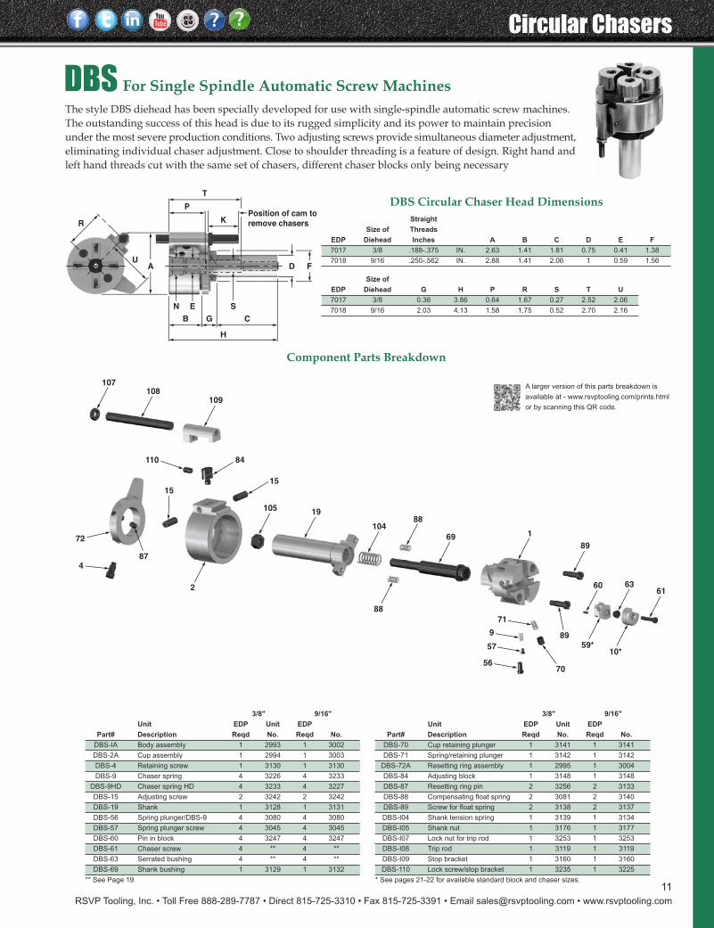
DBS For Single Spindle Automatic Screw MachinesThe style DBS diehead has been specially developed for use with single-spindle automatic screw machines.The outstanding success of this head is due to its rugged simplicity and its power to maintain precisionunder the most severe production conditions. Two adjusting screws provide simultaneous diameter adjustment,eliminating individual chaser adjustment. Close to shoulder threading is a feature of design. Right hand andleft hand threads cut with the same set of chasers, different chaser blocks only being necessary
60 63
59*
5670
89
61
89
169
88104
19105
15
84110
15
109108
107
57
9
71
10*
88
2
4
72
87
A larger version of this parts breakdown is
available at - www.rsvptooling.com/prints.html
or by scanning this QR code.
3/8" 9/16"
Unit EDP Unit EDP
Part# Description Reqd No. Reqd No.
DBS-IA Body assembly 1 2993 1 3002
DBS-2A Cup assembly 1 2994 1 3003
DBS-4 Retaining screw 1 3130 1 3130
DBS-9 Chaser spring 4 3226 4 3233
DBS-9HD Chaser spring HD 4 3233 4 3227
DBS-15 Adjusting screw 2 3242 2 3242
DBS-19 Shank 1 3128 1 3131
DBS-56 Spring plunger/DBS-9 4 3080 4 3080
DBS-57 Spring plunger screw 4 3045 4 3045
DBS-60 Pin in block 4 3247 4 3247
DBS-61 Chaser screw 4 ** 4 **
DBS-63 Serrated bushing 4 ** 4 **
DBS-69 Shank bushing 1 3129 1 3132
** See Page 19
3/8" 9/16"
Unit EDP Unit EDP
Part# Description Reqd No. Reqd No.
DBS-70 Cup retaining plunger 1 3141 1 3141
DBS-71 Spring/retaining plunger 1 3142 1 3142
DBS-72A Resetting ring assembly 1 2995 1 3004
DBS-84 Adjusting block 1 3148 1 3148
DBS-87 Resetting ring pin 2 3256 2 3133
DBS-88 Compensating float spring 2 3081 2 3140
DBS-89 Screw for float spring 2 3138 2 3137
DBS-I04 Shank tension spring 1 3139 1 3134
DBS-I05 Shank nut 1 3176 1 3177
DBS-I07 Lock nut for trip rod 1 3253 1 3253
DBS-I08 Trip rod 1 3119 1 3119
DBS-I09 Stop bracket 1 3160 1 3160
DBS-110 Lock screw/stop bracket 1 3235 1 3225
* See pages 21-22 for available standard block and chaser sizes.
Component Parts Breakdown
Straight
Size of Threads
EDP Diehead Inches A B C D E F
7017 3/8 .188-.375 IN. 2.63 1.41 1.81 0.75 0.41 1.38
7018 9/16 .250-.562 IN. 2.88 1.41 2.06 1 0.59 1.56
Size of
EDP Diehead G H P R S T U
7017 3/8 0.38 3.86 0.64 1.67 0.27 2.52 2.06
7018 9/16 2.03 4.13 1.58 1.75 0.52 2.70 2.16
DBS Circular Chaser Head Dimensions
12
Circular Chasers
RSVP Tooling, Inc. • Toll Free 888-289-7787 • Direct 815-725-3310 • Fax 815-725-3391 • Email [email protected] • www.rsvptooling.com
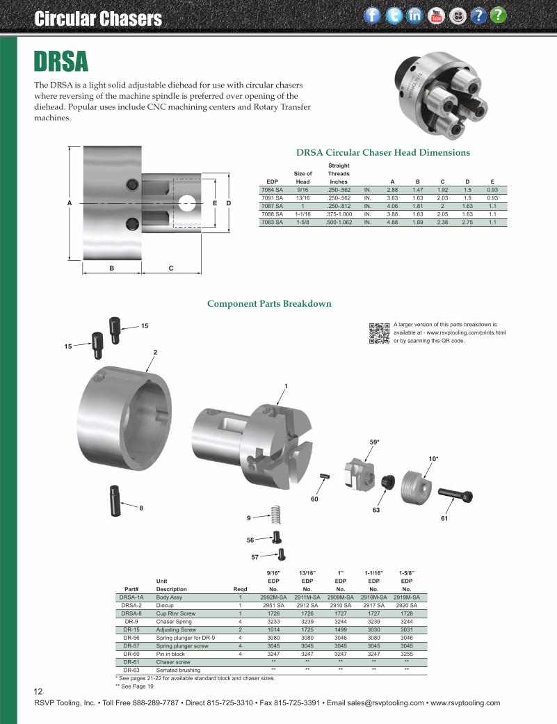
DRSAThe DRSA is a light solid adjustable diehead for use with circular chaserswhere reversing of the machine spindle is preferred over opening of thediehead. Popular uses include CNC machining centers and Rotary Transfermachines.
1
60
63
61
59*
10*
2
56
9
57
8
15
15
A E D
B C
A larger version of this parts breakdown is
available at - www.rsvptooling.com/prints.html
or by scanning this QR code.
9/16" 13/16” 1” 1-1/16” 1-5/8”
Unit EDP EDP EDP EDP EDP
Part# Description Reqd No. No. No. No. No.
DRSA-1A Body Assy 1 2992M-SA 2911M-SA 2909M-SA 2916M-SA 2919M-SA
DRSA-2 Diecup 1 2951 SA 2912 SA 2910 SA 2917 SA 2920 SA
DRSA-8 Cup Rtnr Screw 1 1726 1726 1727 1727 1728
DR-9 Chaser Spring 4 3233 3239 3244 3239 3244
DR-15 Adjusting Screw 2 1014 1725 1499 3030 3031
DR-56 Spring plunger for DR-9 4 3080 3080 3046 3080 3046
DR-57 Spring plunger screw 4 3045 3045 3045 3045 3045
DR-60 Pin in block 4 3247 3247 3247 3247 3255
DR-61 Chaser screw ** ** ** ** **
DR-63 Serrated brushing ** ** ** ** **
* See pages 21-22 for available standard block and chaser sizes.
** See Page 19
Component Parts Breakdown
Straight
Size of Threads
EDP Head Inches A B C D E
7084 SA 9/16 .250-.562 IN. 2.88 1.47 1.92 1.5 0.93
7091 SA 13/16 .250-.562 IN. 3.63 1.63 2.03 1.5 0.93
7087 SA 1 .250-.812 IN. 4.06 1.81 2 1.63 1.1
7088 SA 1-1/16 .375-1.000 IN. 3.88 1.63 2.05 1.63 1.1
7083 SA 1-5/8 .500-1.062 IN. 4.88 1.89 2.38 2.75 1.1
DRSA Circular Chaser Head Dimensions
13
RSVP Tooling, Inc. • Toll Free 888-289-7787 • Direct 815-725-3310 • Fax 815-725-3391 • Email [email protected] • www.rsvptooling.com
Circular Chasers
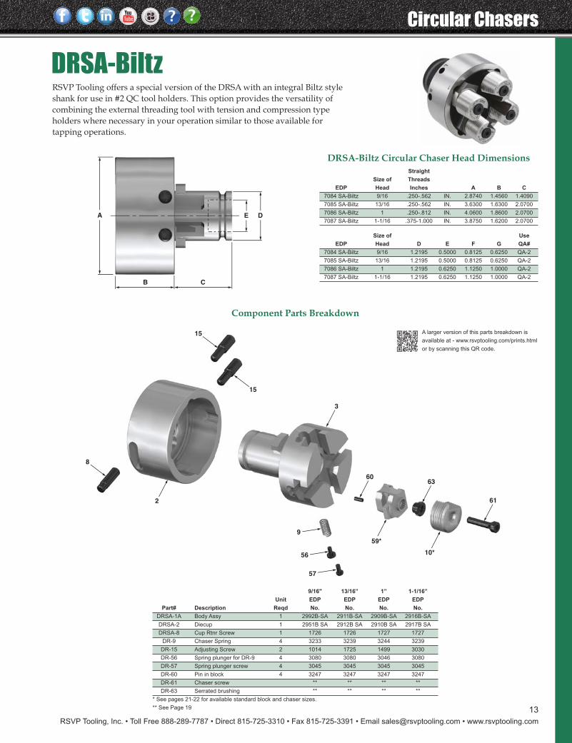
DRSA-BiltzRSVP Tooling offers a special version of the DRSA with an integral Biltz styleshank for use in #2 QC tool holders. This option provides the versatility ofcombining the external threading tool with tension and compression typeholders where necessary in your operation similar to those available fortapping operations.
10*
6063
61
59*
3
9
56
57
2
15
8
15
A E D
B C
A larger version of this parts breakdown is
available at - www.rsvptooling.com/prints.html
or by scanning this QR code.
9/16" 13/16” 1” 1-1/16”
Unit EDP EDP EDP EDP
Part# Description Reqd No. No. No. No.
DRSA-1A Body Assy 1 2992B-SA 2911B-SA 2909B-SA 2916B-SA
DRSA-2 Diecup 1 2951B SA 2912B SA 2910B SA 2917B SA
DRSA-8 Cup Rtnr Screw 1 1726 1726 1727 1727
DR-9 Chaser Spring 4 3233 3239 3244 3239
DR-15 Adjusting Screw 2 1014 1725 1499 3030
DR-56 Spring plunger for DR-9 4 3080 3080 3046 3080
DR-57 Spring plunger screw 4 3045 3045 3045 3045
DR-60 Pin in block 4 3247 3247 3247 3247
DR-61 Chaser screw ** ** ** **
DR-63 Serrated brushing ** ** ** **
* See pages 21-22 for available standard block and chaser sizes.
** See Page 19
Component Parts Breakdown
DRSA-Biltz Circular Chaser Head DimensionsStraight
Size of Threads
EDP Head Inches A B C
7084 SA-Biltz 9/16 .250-.562 IN. 2.8740 1.4560 1.4090
7085 SA-Biltz 13/16 .250-.562 IN. 3.6300 1.6300 2.0700
7086 SA-Biltz 1 .250-.812 IN. 4.0600 1.8600 2.0700
7087 SA-Biltz 1-1/16 .375-1.000 IN. 3.8750 1.6200 2.0700
Size of Use
EDP Head D E F G QA#
7084 SA-Biltz 9/16 1.2195 0.5000 0.8125 0.6250 QA-2
7085 SA-Biltz 13/16 1.2195 0.5000 0.8125 0.6250 QA-2
7086 SA-Biltz 1 1.2195 0.6250 1.1250 1.0000 QA-2
7087 SA-Biltz 1-1/16 1.2195 0.6250 1.1250 1.0000 QA-2
Circular Chasers
RSVP Tooling, Inc. • Toll Free 888-289-7787 • Direct 815-725-3310 • Fax 815-725-3391 • Email [email protected] • www.rsvptooling.com
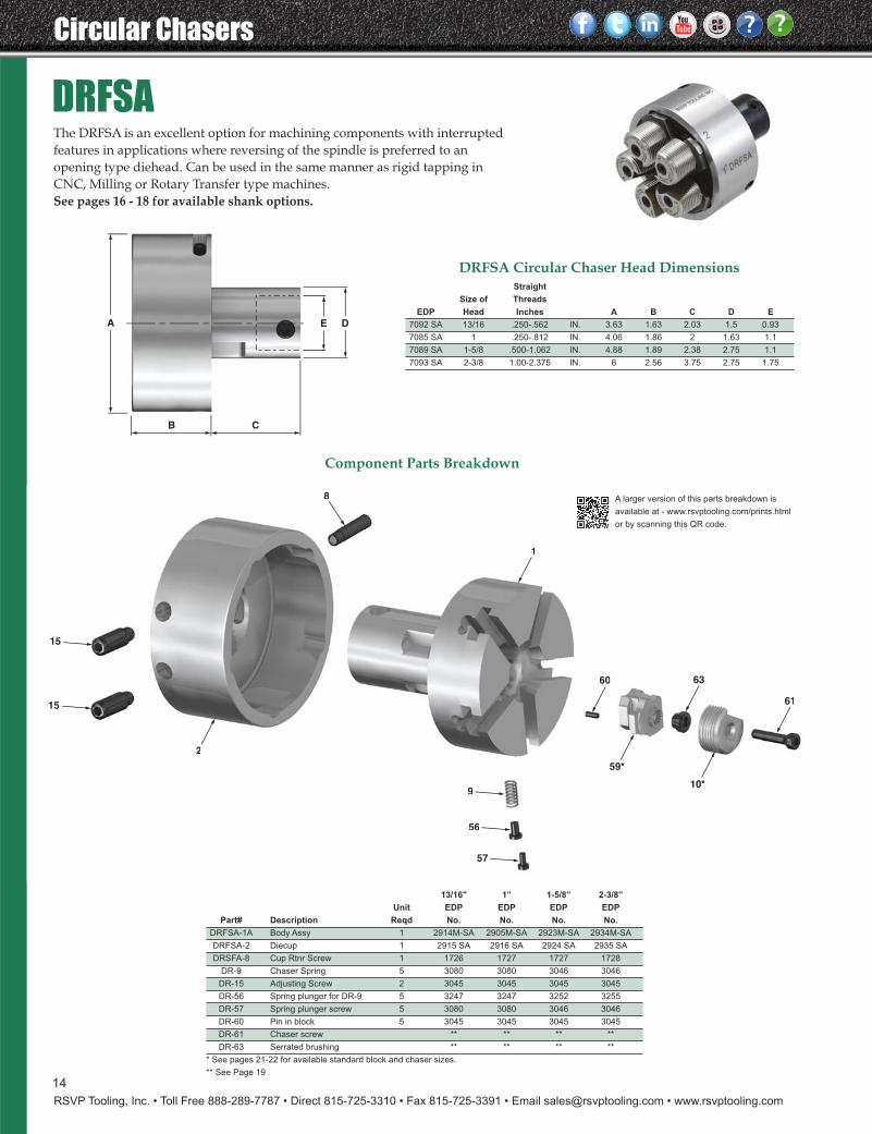
DRFSAThe DRFSA is an excellent option for machining components with interruptedfeatures in applications where reversing of the spindle is preferred to anopening type diehead. Can be used in the same manner as rigid tapping inCNC, Milling or Rotary Transfer type machines.See pages 16 - 18 for available shank options.
2
8
1
59*
61
6360
10*
15
15
56
9
57
2
8
1
59*
61
6360
10*
56
9
57
A E D
B C
14
A larger version of this parts breakdown is
available at - www.rsvptooling.com/prints.html
or by scanning this QR code.
13/16" 1” 1-5/8” 2-3/8”
Unit EDP EDP EDP EDP
Part# Description Reqd No. No. No. No.
DRFSA-1A Body Assy 1 2914M-SA 2905M-SA 2923M-SA 2934M-SA
DRFSA-2 Diecup 1 2915 SA 2916 SA 2924 SA 2935 SA
DRSFA-8 Cup Rtnr Screw 1 1726 1727 1727 1728
DR-9 Chaser Spring 5 3080 3080 3046 3046
DR-15 Adjusting Screw 2 3045 3045 3045 3045
DR-56 Spring plunger for DR-9 5 3247 3247 3252 3255
DR-57 Spring plunger screw 5 3080 3080 3046 3046
DR-60 Pin in block 5 3045 3045 3045 3045
DR-61 Chaser screw ** ** ** **
DR-63 Serrated brushing ** ** ** **
* See pages 21-22 for available standard block and chaser sizes.
** See Page 19
Component Parts Breakdown
Straight
Size of Threads
EDP Head Inches A B C D E
7092 SA 13/16 .250-.562 IN. 3.63 1.63 2.03 1.5 0.93
7085 SA 1 .250-.812 IN. 4.06 1.86 2 1.63 1.1
7089 SA 1-5/8 .500-1.062 IN. 4.88 1.89 2.38 2.75 1.1
7093 SA 2-3/8 1.00-2.375 IN. 6 2.56 3.75 2.75 1.75
DRFSA Circular Chaser Head Dimensions
RSVP Tooling, Inc. • Toll Free 888-289-7787 • Direct 815-725-3310 • Fax 815-725-3391 • Email [email protected] • www.rsvptooling.com
Circular Chasers
15
CUSTOM Circular Chaser Heads
SPECIAL SERVICES Price Upon RequestNYLOX Screws - Replace conventional screws with NYLOXscrews to prevent dieheads from prematurely opening.
Black Oxide Diehead Bodies - Increase tool life, combatoxidation from setting in during machine's idle time.
Keeper Key Slots - Prevent tool pull out; let us modify yourdiehead shanks.
Single Replacement Circular Chasers and Blocks - Theremay come a time when you need just one chaser or block tocomplete a set. Let us know, we can complete that set andhave it running again.
Special Diehead Shanks - The shanks can be manufacturedto any configuration to suit your needs.
Premium Grade Materials - S-390 and ASP23 grade materialswill increase your cutting and chaser tool life at a fraction ofthe cost.
Refurbish and Repair Dieheads - All repairs done by ourfactory trained personnel. If the repair estimate is too costly,or beyond repair, you may trade in your old diehead for acredit on the purchase of a new diehead.
Complete Diehead refurbishment options availableincluding regrind of cup cam and shank / die body reworkwhen specific conditions are present.
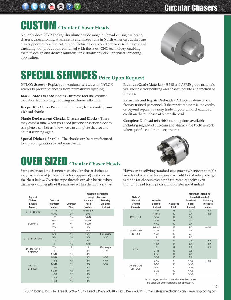
Standard threading diameters of circular chaser dieheadsmay be increased (subject to factory approval) as shown inthe chart below. Oversize pipe threads can also be cut whendiameters and length of threads are within the limits shown.
Not only does RSVP Tooling distribute a wide range of thread cutting die heads,chasers, thread rolling attachments and thread rolls in North America but they arealso supported by a dedicated manufacturing division. They have 60 plus years ofthreading tool production, combined with the latest CNC technology, enablingthem to design and deliver solutions for virtually any circular chaser threading application.
However, specifying standard equipment whenever possibleavoids delay and extra expense. An additional set-up chargeis made for chasers over standard rated capacity eventhough thread form, pitch and diameter are standard
OVER SIZED Circular Chaser Heads
Maximum Threading
Style of Length (Oversize)
Diehead Oversize Standard Reboring
& Rated Diameter Coarsest Head Die Body
Capacity (inches) Pitch (inches) (inches)
DR-DRD-5/1611/32 18 Full length
15/32 20 9/16
1/2 13 3-7/16
9/16 18 2-5/16
DBS-9/16 3/4 16 1-5/16
7/8 18 3/4
1 18 9/16
5/8 11 15/16 Full length
DR-DRD-DS-9/163/4 16 3/4 1-1/8
7/8 18 3/4
1 18 9/16
DR-DS-13/167/8 9 1 Full length
DRF-DSF1 14 3/4 1-1/4
1-3/16 16 3/4
1-1/16 12 3/4 4-3/8
1-1/8 12 3/4 1-1/4
DR-DS-11-3/16 12 3/4 1-1/4
DRF-DSF1-1/4 12 3/4
1-5/16 12 3/4
1-3/8 12 3/4
1-1/2 16 3/4
1-5/8 16 3/4
Maximum Threading
Style of Length (Oversize)
Diehead Oversize Standard Reboring
& Rated Diameter Coarsest Head Die Body
Capacity (inches) Pitch (inches) (inches)
1-1/8 12 3/4 1-1/2
1-3/16 12 3/4 1-1/2
DR-1-1/16 1-1/4 12 3/4
1-3/8 12 3/4
1-1/2 16 3/4
1-11/16 12 7/8 4-3/8
DR-DS-1-5/8 1-3/4 12 7/8
DRF-DSF 1-7/8 12 7/8
2 12 7/8
1-3/4 12 7/8 4-3/8
1-7/8 12 7/8 1-1/2
DR-22 12 7/8 1-1/2
2-1/8 12 7/8
2-1/4 12 7/8
2-3/8 16 7/8
2-1/2 8 1-1/8 5-1/2
DR-DS-2-3/82-5/8 10 1-1/8
DRF-DSF2-3/4 10 1-1/8
2-7/8 10 1-1/8
3 10 1-1/8
Note: Larger oversize thread diameter than those
indicated will be consIdered upon application.
Circular Chasers
RSVP Tooling, Inc. • Toll Free 888-289-7787 • Direct 815-725-3310 • Fax 815-725-3391 • Email [email protected] • www.rsvptooling.com
16
STRAIGHT
MODULAR AUTO
STRAIGHT COOLANT
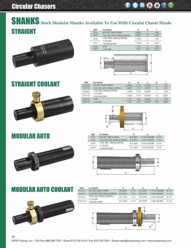
SHANKS Stock Modular Shanks Available To Use With Circular Chaser Heads
A
L
D
A
CL
D
B
A
L
D
MODULAR AUTO COOLANT
A
CL
D
B
EDP For Model A D L
0110 9/16 DR, DRD & DRSA 0.9251 1 1.82
0111 13/16 DR, DRF, DRSA & DRFSA 0.9251 1.5 2.921
0120 1 DR, DRD, DRSA & DRFSA 1.1023 1 1.821-1/16 DR
0117 1-5/8 DR & DRF 1.1023 1.5 2.921
0125 2 DR 1.75 2 1.82
0127 2-3/8 DRF 1.75 2.75 2.921
EDP For Model A B C D L
0110-CI 9/16 DR, DRD & DRSA 0.9251 1.713 0.0787 1 1.82
0111-CI 13/16 DR, DRF, DRSA & DRFSA 0.9251 1.713 0.0787 1.5 2.92
0120-CI 1 DR, DRF, DRSA & DRFSA 1.1023 1.713 0.0787 1 1.821-1/16 DR
0117-CI 1-5/8 DR & DRF 1.1023 1.713 0.0787 1.5 2.921
0125-CI 2 DR 1.75 1.87 0.0787 2 1.82
0127-CI 2-3/8 DRF 1.75 1.87 0.0787 2.75 2.921
EDP For Model A B C D L
0121-CI 9/16 DR, DRD & DRSA Ø 0.9251 1.713 Ø 0.0787 1-1/16-12ACME 6.114
0104-CI 13/16 DR, DRF, DRSA & DRFSA Ø 0.9251 1.713 Ø 0.0787 1-3/8-12ACME 7.114
0116-CI 1 DR, DRF, DRSA & DRFSA Ø 1.1023 1.713 Ø 0.0787 1-1/16-12ACME 6.114
0104-A-CI1-1/16 DR
Ø 1.1023 1.713 Ø 0.0787 1-3/8-12ACME 7.114 1-5/8 DR & DRF
EDP For Model A D L
0121 9/16 DR, DRD & DRSA Ø 0.9251 1-1/16-12ACME 6.114
0104 13/16 DR, DRF, DRSA & DRFSA Ø 0.9251 1-3/8-12ACME 7.114
0116 1 DR, DRF, DRSA & DRFSA Ø 1.1023 1-1/16-12ACME 6.114
0104-A1-1/16 DR
Ø 1.1023 1-3/8-12ACME 7.114 1-5/8 DR & DRF
RSVP Tooling, Inc. • Toll Free 888-289-7787 • Direct 815-725-3310 • Fax 815-725-3391 • Email [email protected] • www.rsvptooling.com
Circular Chasers
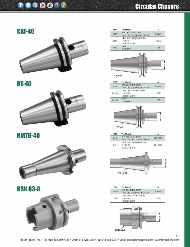
17
BT-40
HSK 63-A
NMTB-40
A
NMTB-40
A
HSK 63-A
CAT-40
A
CAT-40
A
BT-40
EDP For Model A
9/16 DR, DRD & DRSA0109
13/16 DR, DRF, DRSA & DRFSA0.9251
1 DR, DRF, DRSA & DRFSA
0109-A 1-1/16 DR 1.1023
1-5/8 DR & DRF
2 DR0109-B
2-3/8 DRF1.75
EDP For Model A
9/16 DR, DRD & DRSA0108
13/16 DR, DRF, DRSA & DRFSA0.9251
1 DR, DRF, DRSA & DRFSA
0126 1-1/16 DR 1.1023
1-5/8 DR & DRF
2 DR0140
2-3/8 DRF1.75
EDP For Model A
9/16 DR, DRD & DRSA0107
13/16 DR, DRF, DRSA & DRFSA0.9251
1 DR, DRF, DRSA & DRFSA
0138 1-1/16 DR 1.1023
1-5/8 DR & DRF
EDP For Model A
0143 9/16 DR, DRD & DRSA
Ø 0.925113/16 DR, DRF, DRSA & DRFSA
1 DR, DRF, DRSA & DRFSA
0131 1-1/16 DR Ø 1.1023
1-5/8 DR & DRF
Circular Chasers
RSVP Tooling, Inc. • Toll Free 888-289-7787 • Direct 815-725-3310 • Fax 815-725-3391 • Email [email protected] • www.rsvptooling.com
18
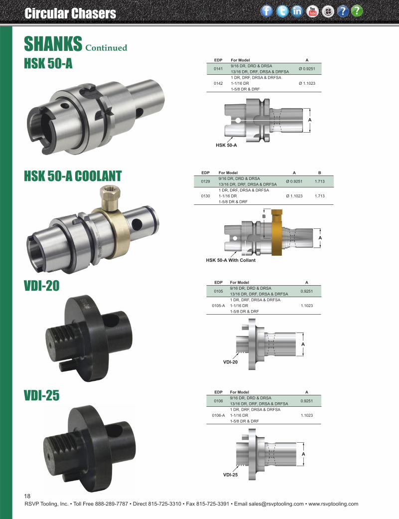
HSK 50-A
VDI-20
HSK 50-A COOLANT
SHANKS Continued
A
HSK 50-A
A
B
HSK 50-A With Collant
A
VDI-20
EDP For Model A
9/16 DR, DRD & DRSA0105
13/16 DR, DRF, DRSA & DRFSA0.9251
1 DR, DRF, DRSA & DRFSA
0105-A 1-1/16 DR 1.1023
1-5/8 DR & DRF
VDI-25
A
VDI-25
EDP For Model A
9/16 DR, DRD & DRSA0106
13/16 DR, DRF, DRSA & DRFSA0.9251
1 DR, DRF, DRSA & DRFSA
0106-A 1-1/16 DR 1.1023
1-5/8 DR & DRF
EDP For Model A B
0129 9/16 DR, DRD & DRSA
Ø 0.9251 1.71313/16 DR, DRF, DRSA & DRFSA
1 DR, DRF, DRSA & DRFSA
0130 1-1/16 DR Ø 1.1023 1.713
1-5/8 DR & DRF
EDP For Model A
0141 9/16 DR, DRD & DRSA
Ø 0.925113/16 DR, DRF, DRSA & DRFSA
1 DR, DRF, DRSA & DRFSA
0142 1-1/16 DR Ø 1.1023
1-5/8 DR & DRF
RSVP Tooling, Inc. • Toll Free 888-289-7787 • Direct 815-725-3310 • Fax 815-725-3391 • Email [email protected] • www.rsvptooling.com
Circular Chasers
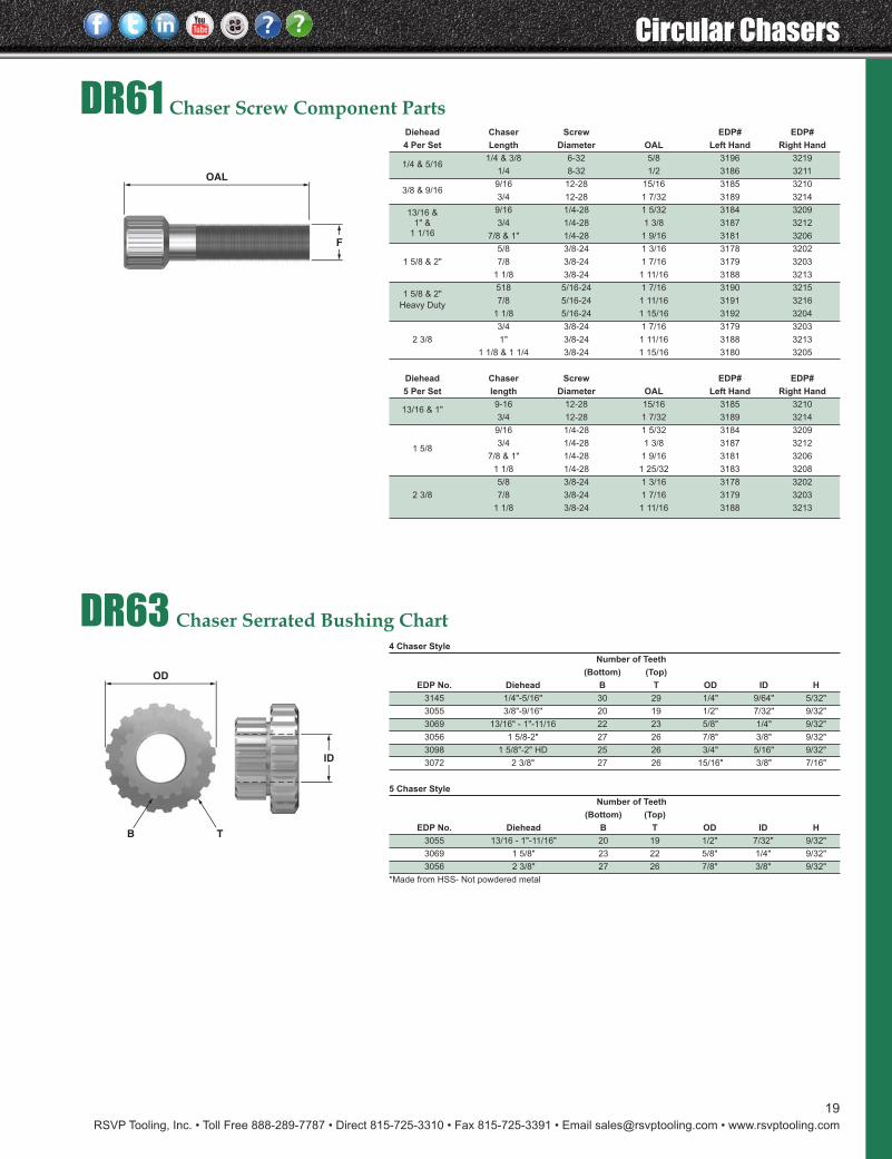
19
DR61 Chaser Screw Component Parts
DR63 Chaser Serrated Bushing Chart
Diehead Chaser Screw EDP# EDP#
4 Per Set Length Diameter OAL Left Hand Right Hand
1/4 & 5/161/4 & 3/8 6-32 5/8 3196 3219
1/4 8-32 1/2 3186 3211
3/8 & 9/169/16 12-28 15/16 3185 3210
3/4 12-28 1 7/32 3189 3214
13/16 & 9/16 1/4-28 1 5/32 3184 3209
1" & 3/4 1/4-28 1 3/8 3187 3212 1 1/16 7/8 & 1" 1/4-28 1 9/16 3181 3206
5/8 3/8-24 1 3/16 3178 3202
1 5/8 & 2" 7/8 3/8-24 1 7/16 3179 3203
1 1/8 3/8-24 1 11/16 3188 3213
1 5/8 & 2"518 5/16-24 1 7/16 3190 3215
Heavy Duty7/8 5/16-24 1 11/16 3191 3216
1 1/8 5/16-24 1 15/16 3192 3204
3/4 3/8-24 1 7/16 3179 3203
2 3/8 1" 3/8-24 1 11/16 3188 3213
1 1/8 & 1 1/4 3/8-24 1 15/16 3180 3205
Diehead Chaser Screw EDP# EDP#
5 Per Set length Diameter OAL Left Hand Right Hand
13/16 & 1"9-16 12-28 15/16 3185 3210
3/4 12-28 1 7/32 3189 3214
9/16 1/4-28 1 5/32 3184 3209
1 5/83/4 1/4-28 1 3/8 3187 3212
7/8 & 1" 1/4-28 1 9/16 3181 3206
1 1/8 1/4-28 1 25/32 3183 3208
5/8 3/8-24 1 3/16 3178 3202
2 3/8 7/8 3/8-24 1 7/16 3179 3203
1 1/8 3/8-24 1 11/16 3188 3213
F
OAL
ID
OD
B T
4 Chaser Style
Number of Teeth
(Bottom) (Top)
EDP No. Diehead B T OD ID H
3145 1/4"-5/16" 30 29 1/4" 9/64" 5/32"
3055 3/8"-9/16" 20 19 1/2" 7/32" 9/32"
3069 13/16" - 1"-11/16 22 23 5/8" 1/4" 9/32"
3056 1 5/8-2" 27 26 7/8" 3/8" 9/32"
3098 1 5/8"-2" HD 25 26 3/4" 5/16" 9/32"
3072 2 3/8" 27 26 15/16" 3/8" 7/16"
5 Chaser Style
Number of Teeth
(Bottom) (Top)
EDP No. Diehead B T OD ID H
3055 13/16 - 1"-11/16" 20 19 1/2" 7/32" 9/32"
3069 1 5/8" 23 22 5/8" 1/4" 9/32"
3056 2 3/8" 27 26 7/8" 3/8" 9/32"
*Made from HSS- Not powdered metal
Circular Chasers
RSVP Tooling, Inc. • Toll Free 888-289-7787 • Direct 815-725-3310 • Fax 815-725-3391 • Email [email protected] • www.rsvptooling.com
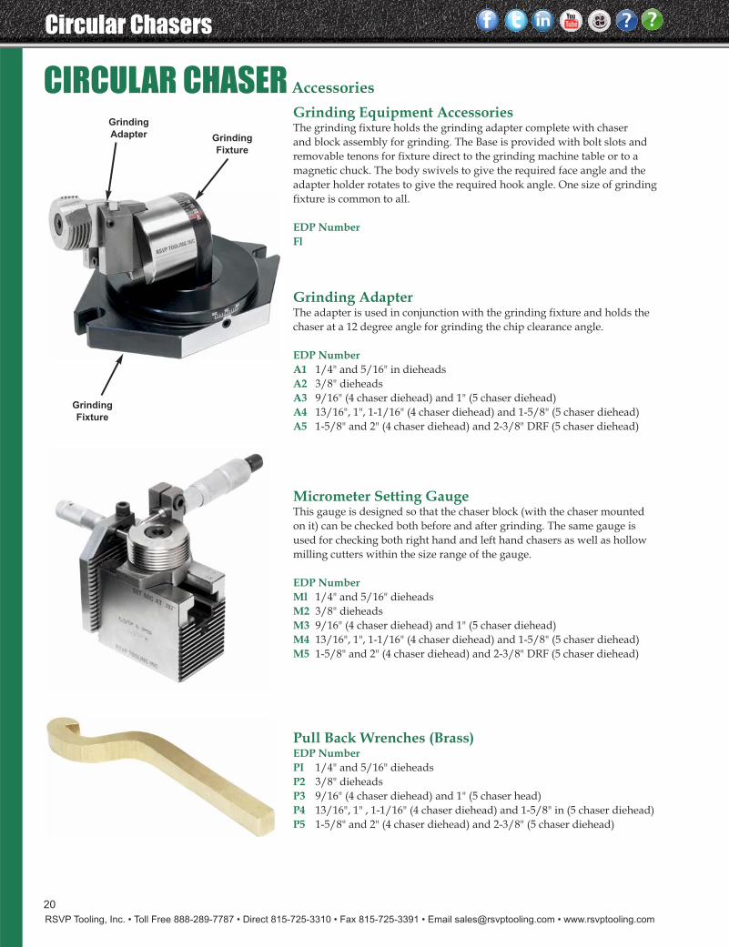
20
Grinding Equipment AccessoriesThe grinding fixture holds the grinding adapter complete with chaser and block assembly for grinding. The Base is provided with bolt slots and removable tenons for fixture direct to the grinding machine table or to a magnetic chuck. The body swivels to give the required face angle and theadapter holder rotates to give the required hook angle. One size of grindingfixture is common to all.
EDP Number Fl
Grinding AdapterThe adapter is used in conjunction with the grinding fixture and holds thechaser at a 12 degree angle for grinding the chip clearance angle.
EDP NumberA1 1/4" and 5/16" in dieheadsA2 3/8" dieheadsA3 9/16" (4 chaser diehead) and 1" (5 chaser diehead)A4 13/16", 1", 1-1/16" (4 chaser diehead) and 1-5/8" (5 chaser diehead) A5 1-5/8" and 2" (4 chaser diehead) and 2-3/8" DRF (5 chaser diehead)
Micrometer Setting GaugeThis gauge is designed so that the chaser block (with the chaser mounted on it) can be checked both before and after grinding. The same gauge is used for checking both right hand and left hand chasers as well as hollowmilling cutters within the size range of the gauge.
EDP NumberMl 1/4" and 5/16" dieheadsM2 3/8" dieheadsM3 9/16" (4 chaser diehead) and 1" (5 chaser diehead)M4 13/16", 1", 1-1/16" (4 chaser diehead) and 1-5/8" (5 chaser diehead) M5 1-5/8" and 2" (4 chaser diehead) and 2-3/8" DRF (5 chaser diehead)
Pull Back Wrenches (Brass)EDP NumberPI 1/4" and 5/16" dieheadsP2 3/8" dieheadsP3 9/16" (4 chaser diehead) and 1" (5 chaser head)P4 13/16", 1" , 1-1/16" (4 chaser diehead) and 1-5/8" in (5 chaser diehead) P5 1-5/8" and 2" (4 chaser diehead) and 2-3/8" (5 chaser diehead)
Grinding
Adapter
Grinding
Fixture
Grinding
Fixture
CIRCULAR CHASER Accessories

RSVP Tooling, Inc. • Toll Free 888-289-7787 • Direct 815-725-3310 • Fax 815-725-3391 • Email [email protected] • www.rsvptooling.com
Circular Chasers
21
CIRCULAR CHASERS & BLOCKS (Standard 4 Per Set)5/16" 4 Per Set Dieheads UN
Circular Chasers
25 45
Chamfer Chamfer Blocks
EDP# EDP# P.P.I./Form EDP#
4001 5001 2-56/UNC 6001
4002 5002 2-64/UNF 6002
4003 5003 3-48/UNC 6003
4004 5004 3-56/UNF 6004
4005 5005 4-40/UNC 6005
4006 5006 4.48/UNF 6006
4007 5007 5.40/UNC 6007
4008 5008 5.44/UNF 6008
4009 5009 6-32/UNC 6009
4010 5010 6-40/UNF 6010
4011 5011 8-32/UNC 6011
4012 5012 8-36/UNF 6012
4013 5013 10-24/UNC 6013
4014 5014 10-32/UNF 6014
4015 5015 12-24/UNC 6015
4016 5016 12-28/UNF 6016
4017 5017 1/4.20/UNC 6017
4018 5018 1/4-28/UNF 6018
4019 5019 5/16-18/UNC 6019
4020 5020 5/16-24/UNF 6020
Pipe
Circular Chasers
25 45
Chamfer Chamfer Blocks
EDP# EDP# Dia./Form EDP#
4021 5021 1/8 NPT/ANPT 6021
4022 5022 1/8 NPTF 6022
9/16" 4 Per Set Dieheads UN
Circular Chasers
25 45
Chamfer Chamfer Blocks
EDP# EDP# P.P.I./Form EDP#
4037 5037 1/4-20/UNC 6037
4038 5038 1/4-28/UNF 6038
4039 5039 5/16-18/UNC 6039
4040 5040 5/16-24/UNF 6040
4041 5041 3/8-16/UNC 6041
4042 5042 3/8-24/UNF 6042
4043 5043 7/16-14/UNC 6043
4044 5044 7/16-20/UNF 6044
4045 5045 1/2-13/UNC 6045
4046 5046 1/2-20/UNF 6046
4047 5047 9/16-12/UNC 6047
4048 5048 9/16-18/UNF 6048
Pipe
Circular Chasers
25 45
Chamfer Chamfer Blocks
EDP# EDP# Dia./Form EDP#
4049 5049 1/8-NPT/ANPT 6049
4050 5050 1/8-NPTF 6050
4051 5051 1/4-NPT/ANPT 6051
4052 5052 1/4-NPTF 6052
4053 5053 3/8-NPTF/ANPT 6053
4054 5054 3/8-NPTF 6054
4055 5055 1/2-NPT/ANPT 6055
4056 5056 1/2-NPTF 6056
3/8" 4 Per Set Dieheads UN
Circular Chasers
25 45
Chamfer Chamfer Blocks
EDP# EDP# P.P.I./Form EDP#
4023 5023 8-32/UNC 6023
4024 5024 8-36/UNF 6024
4025 5025 10-24/UNC 6025
4026 5026 10-32/UNF 6026
4027 5027 12-24/UNC 6027
4028 5028 12-28/UNF 6028
4029 5029 1/4-20/UNC 6029
4030 5030 1/4-28/UNF 6030
4031 5031 5/16-18/UNC 6031
4032 5032 5/16-24/UNF 6032
4033 5033 3/8-16/UNC 6033
4034 5034 3/8-24/UNF 6034
Pipe
Circular Chasers
25 45
Chamfer Chamfer Blocks
EDP# EDP# Dia./Form EDP#
4035 5035 1/8 NPT/ANPT 6035
4036 5036 1/8 NPTF 6036
13/16" 4 Per Set Dieheads UN
Circular Chasers
25 45
Chamfer Chamfer Blocks
EDP# EDP# P.P.I./Form EDP#
4057 5057 1/4-20/UNC 6057
4058 5058 1/4-28/UNF 6058
4059 5059 5/16-18/UNC 6059
4060 5060 5/16-24/UNF 6060
4061 5061 3/8-16/UNC 6061
4062 5062 3/8-24/UNF 6062
4063 5063 7/16-14/UNC 6063
4064 5064 7/16-20/UNF 6064
4065 5065 1/2-13/UNC 6065
4066 5066 1/2-20/UNF 6066
4067 5067 9/16-12/UNC 6067
4068 5068 9/16-18/UNF 6068
4069 5069 5/8-11/UNC 6069
4070 5070 5/8-18/UNF 6070
4071 5071 3/4-10/UNC 6071
4072 5072 3/4-16/UNF 6072
Pipe
Circular Chasers
25 45
Chamfer Chamfer Blocks
EDP# EDP# Dia./Form EDP#
4073 5073 1/8 NPT/ANPT 6073
4074 5074 1/8 NPTF 6074
4075 5075 1/4 NPT/ANPT 6075
4076 5076 1/4 NPTF 6076
4077 5077 3/8 NPT/ANPT 6077
4078 5078 3/8 NPTF 6078
4079 5079 1/2 NPT/ANPT 6079
4080 5080 1/2 NPTF 6080
1" 4 Per Set Dieheads UN
Circular Chasers
25 45
Chamfer Chamfer Blocks
EDP# EDP# P.P.I./Form EDP#
4081 5081 7/16-14/UNC 6081
4082 5082 7/16-20/UNF 6082
4083 5083 1/2-13/UNC 6083
4084 5084 1/2-20/UNF 6084
4085 5085 9/16-12/UNC 6085
4086 5086 9/16-18/UNF 6086
4087 5087 5/8-11/UNC 6087
4088 5088 5/8-18/UNF 6088
4089 5089 3/4-10/UNC 6089
4090 5090 3/4-16/UNF 6090
4091 5091 7/8-9/UNC 6091
4092 5092 7/8-14/UNF 6092
4093 5093 1-8/UNC 6093
4094 5094 1-12/UNF 6094
Pipe
Circular Chasers
25 45
Chamfer Chamfer Blocks
EDP# EDP# P.P.I./Form EDP#
4095 5095 1/8 NPT/ANPT 6095
4096 5096 1/8 NPTF 6096
4097 5097 1/4 NPT/ANPT 6097
4098 5098 1/4 NPTF 6098
4099 5099 3/8 NPT/ANPT 6099
4100 5100 3/8 NPTF 6100
4101 5101 1/2 NPT/ANPT 6101
4102 5102 1/2 NPTF 6102
4103 5103 3/4 NPT/ANPT 6103
4104 5104 3/4 NPTF 6104
1-5/8" 4 Per Set Dieheads UN
Circular Chasers
25 45
Chamfer Chamfer Blocks
EDP# EDP# P.P.I./Form EDP#
4149 5149 1/2-13/UNC 6149
4150 5150 1/2-20/UNF 6150
4151 5151 9/16-12/UNC 6151
4152 5152 9/16-18/UNF 6152
4153 5153 5/8-11/UNC 6153
4154 5154 5/8-18/UNF 6154
4155 5155 3/4-10/UNC 6155
4156 5156 3/4-16/UNF 6156
4157 5157 7/8-9/UNC 6157
4158 5158 7/8-14/UNF 6158
4159 5159 1-8/UNC 6159
4160 5160 1-12/UNF 6160
4161 5161 11/8-7/UNC 6161
4162 5162 11/8-12/UNF 6162
4163 5163 1 1/4-7/UNC 6163
4164 5164 1 1/4-12/UNF 6164
4165 5165 13/8-12/UNF 6165
4166 5166 11/2-12/UNF 6166
Pipe
Circular Chasers
25 45
Chamfer Chamfer Blocks
EDP# EDP# P.P.I./Form EDP#
4167 5167 1/4 NPT/ANPT 6167
4168 5168 1/4 NPTF 6168
4169 5169 3/8 NPT/ANPT 6169
4170 5170 3/8 NPTF 6170
4171 5171 1/2 NPT/ANPT 6171
4172 5172 1/2 NPTF 6172
4173 5173 3/4 NPT/ANPT 6173
4174 5174 3/4 NPTF 6174
4175 5175 I NPT/ANPT 6175
4176 5176 I NPTF 6176
4177 5177 1 1/4NPT/ANPT 6177
4178 5178 1 1/4NPTF 6178
11/16" 4 Per Set Dieheads UN
Circular Chasers
25 45
Chamfer Chamfer Blocks
EDP# EDP# P.P.I./Form EDP#
4127 5127 1/2-13/UNC 6127
4128 5128 1/2-20/UNF 6128
4129 5129 9/16-12/UNC 6129
4130 5130 9/16-18/UNF 6130
4131 5131 5/8-11/UNC 6131
4132 5132 5/8-18/UNF 6132
4133 5133 3/4-10/UNC 6133
4134 5134 3/4-16/UNF 6134
4135 5135 7/8-9/UNC 6135
4136 5136 7/8-14/UNF 6136
4137 5137 1-8/UNC 6137
4138 5138 1-12/UNF 6138
Pipe
Circular Chasers
25 45
Chamfer Chamfer Blocks
EDP# EDP# P.P.I./Form EDP#
4139 5139 1/8 NPT/ANPT 6139
4140 5140 1/8 NPTF 6140
4141 5141 1/4 NPT/ANPT 6141
4142 5142 1/4 NPTF 6142
4143 5143 3/8 NPT/ANPT 6143
4144 5144 3/8 NPTF 6144
4145 5145 1/2 NPT/ANPT 6145
4146 5146 1/2 NPTF 6146
4147 5147 3/4 NPT/ANPT 6147
4148 5148 3/4 NPTF 6148
2" 4 Per Set Dieheads UN
Circular Chasers
25 45
Chamfer Chamfer Blocks
EDP# EDP# P.P.I./Form EDP#
4209 5209 3/4-10/UNC 6209
4210 5210 3/4-16/UNF 6210
4211 5211 7/8-9/UNC 6211
4212 5212 7/8-14/UNF 6212
4213 5213 1-8/UNC 6213
4214 5214 1-12/UNF 6214
4215 5215 1 1/8-7/UNC 6215
4216 5216 1 1/8-12/UNF 6216
4217 5217 1 1/4-7/UNC 6217
4218 5218 1 1/4-12/UNF 6218
4219 5219 1 3/8-12/UNF 6219
4220 5220 1 1/2-12/UNF 6220
Pipe
Circular Chasers
25 45
Chamfer Chamfer Blocks
EDP# EDP# P.P.I./Form EDP#
4221 5221 1/2 NPT/ANPT 6221
4222 5222 1/2 NPTF 6222
4223 5223 3/4 NPT/ANPT 6223
4224 5224 3/4 NPTF 6224
4225 5225 1 NPT/ANPT 6225
4226 5226 1" NPTF 6226
4227 5227 1 1/4 NPT/ANPT 6227
4228 5228 1 1/4 NPTF 6228
4229 5229 1 1/2 NPT/ANPT 6229
4230 5230 1 1/2 NPTF 6230
Circular Chasers
RSVP Tooling, Inc. • Toll Free 888-289-7787 • Direct 815-725-3310 • Fax 815-725-3391 • Email [email protected] • www.rsvptooling.com
22
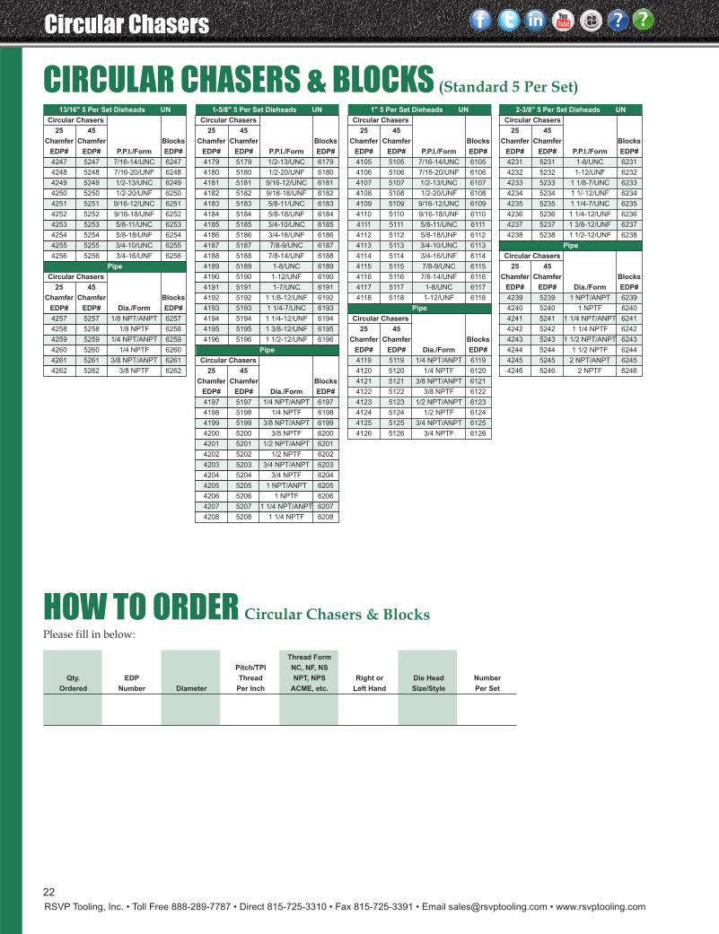
CIRCULAR CHASERS & BLOCKS (Standard 5 Per Set)1" 5 Per Set Dieheads UN
Circular Chasers
25 45
Chamfer Chamfer Blocks
EDP# EDP# P.P.I./Form EDP#
4105 5105 7/16-14/UNC 6105
4106 5106 7/16-20/UNF 6106
4107 5107 1/2-13/UNC 6107
4108 5108 1/2-20/UNF 6108
4109 5109 9/16-12/UNC 6109
4110 5110 9/16-18/UNF 6110
4111 5111 5/8-11/UNC 6111
4112 5112 5/8-18/UNF 6112
4113 5113 3/4-10/UNC 6113
4114 5114 3/4-16/UNF 6114
4115 5115 7/8-9/UNC 6115
4116 5116 7/8-14/UNF 6116
4117 5117 1-8/UNC 6117
4118 5118 1-12/UNF 6118
Pipe
Circular Chasers
25 45
Chamfer Chamfer Blocks
EDP# EDP# Dia./Form EDP#
4119 5119 1/4 NPT/ANPT 6119
4120 5120 1/4 NPTF 6120
4121 5121 3/8 NPT/ANPT 6121
4122 5122 3/8 NPTF 6122
4123 5123 1/2 NPT/ANPT 6123
4124 5124 1/2 NPTF 6124
4125 5125 3/4 NPT/ANPT 6125
4126 5126 3/4 NPTF 6126
2-3/8" 5 Per Set Dieheads UN
Circular Chasers
25 45
Chamfer Chamfer Blocks
EDP# EDP# P.P.I./Form EDP#
4231 5231 1-8/UNC 6231
4232 5232 1-12/UNF 6232
4233 5233 1 1/8-7/UNC 6233
4234 5234 1 1/-12/UNF 6234
4235 5235 1 1/4-7/UNC 6235
4236 5236 1 1/4-12/UNF 6236
4237 5237 1 3/8-12/UNF 6237
4238 5238 1 1/2-12/UNF 6238
Pipe
Circular Chasers
25 45
Chamfer Chamfer Blocks
EDP# EDP# Dia./Form EDP#
4239 5239 1 NPT/ANPT 6239
4240 5240 1 NPTF 6240
4241 5241 1 1/4 NPT/ANPT 6241
4242 5242 1 1/4 NPTF 6242
4243 5243 1 1/2 NPT/ANPT 6243
4244 5244 1 1/2 NPTF 6244
4245 5245 2 NPT/ANPT 6245
4246 5246 2 NPTF 6246
1-5/8" 5 Per Set Dieheads UN
Circular Chasers
25 45
Chamfer Chamfer Blocks
EDP# EDP# P.P.I./Form EDP#
4179 5179 1/2-13/UNC 6179
4180 5180 1/2-20/UNF 6180
4181 5181 9/16-12/UNC 6181
4182 5182 9/16-18/UNF 6182
4183 5183 5/8-11/UNC 6183
4184 5184 5/8-18/UNF 6184
4185 5185 3/4-10/UNC 6185
4186 5186 3/4-16/UNF 6186
4187 5187 7/8-9/UNC 6187
4188 5188 7/8-14/UNF 6188
4189 5189 1-8/UNC 6189
4190 5190 1-12/UNF 6190
4191 5191 1-7/UNC 6191
4192 5192 1 1/8-12/UNF 6192
4193 5193 1 1/4-7/UNC 6193
4194 5194 1 1/4-12/UNF 6194
4195 5195 1 3/8-12/UNF 6195
4196 5196 1 1/2-12/UNF 6196
Pipe
Circular Chasers
25 45
Chamfer Chamfer Blocks
EDP# EDP# Dia./Form EDP#
4197 5197 1/4 NPT/ANPT 6197
4198 5198 1/4 NPTF 6198
4199 5199 3/8 NPT/ANPT 6199
4200 5200 3/8 NPTF 6200
4201 5201 1/2 NPT/ANPT 6201
4202 5202 1/2 NPTF 6202
4203 5203 3/4 NPT/ANPT 6203
4204 5204 3/4 NPTF 6204
4205 5205 1 NPT/ANPT 6205
4206 5206 1 NPTF 6206
4207 5207 1 1/4 NPT/ANPT 6207
4208 5208 1 1/4 NPTF 6208
13/16" 5 Per Set Dieheads UN
Circular Chasers
25 45
Chamfer Chamfer Blocks
EDP# EDP# P.P.I./Form EDP#
4247 5247 7/16-14/UNC 6247
4248 5248 7/16-20/UNF 6248
4249 5249 1/2-13/UNC 6249
4250 5250 1/2-20/UNF 6250
4251 5251 9/16-12/UNC 6251
4252 5252 9/16-18/UNF 6252
4253 5253 5/8-11/UNC 6253
4254 5254 5/8-18/UNF 6254
4255 5255 3/4-10/UNC 6255
4256 5256 3/4-16/UNF 6256
Pipe
Circular Chasers
25 45
Chamfer Chamfer Blocks
EDP# EDP# Dia./Form EDP#
4257 5257 1/8 NPT/ANPT 6257
4258 5258 1/8 NPTF 6258
4259 5259 1/4 NPT/ANPT 6259
4260 5260 1/4 NPTF 6260
4261 5261 3/8 NPT/ANPT 6261
4262 5262 3/8 NPTF 6262
HOW TO ORDER Circular Chasers & Blocks
Thread Form
Pitch/TPI NC, NF, NS
Qty. EDP Thread NPT, NPS Right or Die Head Number
Ordered Number Diameter Per Inch ACME, etc. Left Hand Size/Style Per Set
Please fill in below:
RSVP Tooling, Inc. • Toll Free 888-289-7787 • Direct 815-725-3310 • Fax 815-725-3391 • Email [email protected] • www.rsvptooling.com
23
Geometeric Chasers
RSVP Tooling now offers a comprehensive selection of threadcutting diehead options to consider for virtually any job lotsize or application. We are proud to offer an economic solutionto suit any requirement.
D Style dieheads are commonly used in automatic or manualoperations, mounted in a fixed, stationary position in a turretor tool holder. Known as self opening type heads, they pullopen when feed is stopped and are reset to the closed positionby use of a reset lever actuated by hand or index of the machine.
DJ Style dieheads utilize the same chasers as D style heads and are made to withstand the same heavy duty applications.DJ heads are used where an opening type head is not mechanically supported or preferred. Referred to as solid adjustable type, DJ heads are suited to threading operationswhere reversing of the spindle is preferred such as in millingmachines or lead screw controlled applications. They can bemounted in a fixed or rotating position.
GEOMETRIC CHASER System
D-Style - Overview & Components ...................................23 - 24DJ - Overview & Components ..................................................25SAMN - Overview & Components ..........................................26SAMAN - Overview & Components ........................................27Geometric Chaser Specs & Terms .....................................28 - 29How To Order Geometric Chasers ...........................................29
Samn & Saman Style dieheads are a simple, durable design offering an attractive alternative to acorn type die chasers.Their one piece construction and ample thread size rangeoffer an economic solution for short run applications andthose with limited clearance. The SAMN style heads are abasic straight shank design whereas the SAMAN heads areofferd with threaded bodies to screw directly onto standard#1 through #4 acorn holders.
Note: As is the case with all RSVP Tooling Dieheads, we canmanufacture any head with customer specific requirementssuch as ground pilot bore, tap adapter fitting and virtuallyany shank configuration.
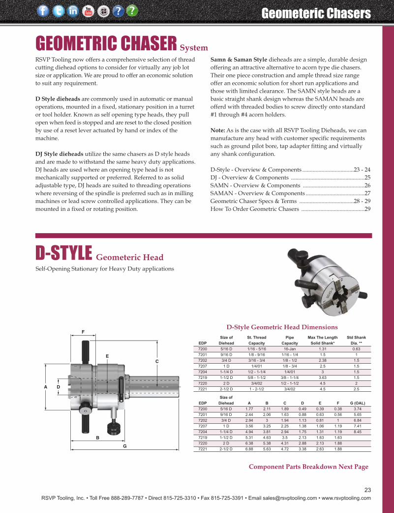
D-STYLE Geometeric HeadSelf-Opening Stationary for Heavy Duty applications
A
C
D
E
F
G
B
Size of St. Thread Pipe Max The Length Std Shank
EDP Diehead Capacity Capacity Solid Shank* Dia. **
7200 5/16 D 1/16 - 5/16 16-Jan 1.31 0.63
7201 9/16 D 1/8 - 9/16 1/16 - 1/4 1.5 1
7202 3/4 D 3/16 - 3/4 1/8 - 1/2 2.38 1.5
7207 1 D 1/4/01 1/8 - 3/4 2.5 1.5
7204 1-1/4 D 1/2 - 1-1/4 1/4/01 3 1.5
7219 1-1/2 D 5/8 - 1-1/2 3/8 - 1-1/4 3.63 1.5
7220 2 D 3/4/02 1/2 - 1-1/2 4.5 2
7221 2-1/2 D 1 - 2-1/2 3/4/02 4.5 2.5
Size of
EDP Diehead A B C D E F G (OAL)
7200 5/16 D 1.77 2.11 1.89 0.49 0.39 0.38 3.74
7201 9/16 D 2.44 2.06 1.63 0.88 0.63 0.56 5.65
7202 3/4 D 2.94 3 1.94 1.13 0.81 1 6.84
7207 1 D 3.56 3.25 2.25 1.38 1.06 1.19 7.41
7204 1-1/4 D 4.94 3.81 2.94 1.75 1.31 1.19 8.45
7219 1-1/2 D 5.31 4.63 3.5 2.13 1.63 1.63
7220 2 D 6.38 5.38 4.31 2.88 2.13 1.88
7221 2-1/2 D 6.88 5.63 4.72 3.38 2.63 1.88
D-Style Geometric Head Dimensions
Component Parts Breakdown Next Page
Geometeric Chasers
RSVP Tooling, Inc. • Toll Free 888-289-7787 • Direct 815-725-3310 • Fax 815-725-3391 • Email [email protected] • www.rsvptooling.com
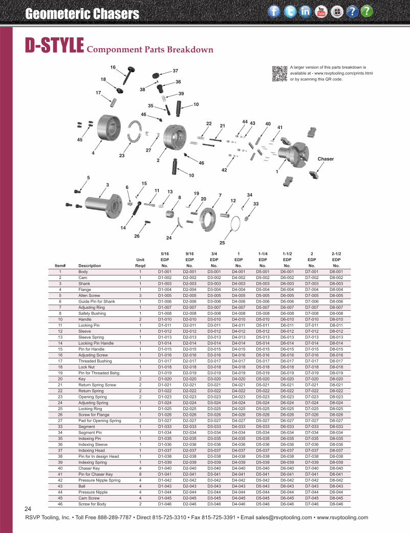
D-STYLE Componment Parts Breakdown
Chaser
41
34
3312
720
198
1311
156
3
5
40434421
22
10
46
38
35
16
18
17 39
36
37
142
46
10
2
2425
26
14
2723
4
45
24
A larger version of this parts breakdown is
available at - www.rsvptooling.com/prints.html
or by scanning this QR code.
5/16 9/16 3/4 1 1-1/4 1-1/2 2 2-1/2
Unit EDP EDP EDP EDP EDP EDP EDP EDP
Item# Description Reqd No. No. No. No. No. No. No. No.
1 Body 1 D1-001 D2-001 D3-001 D4-001 D5-001 D6-001 D7-001 D8-001
2 Cam 1 D1-002 D2-002 D3-002 D4-002 D5-002 D6-002 D7-002 D8-002
3 Shank 1 D1-003 D2-003 D3-003 D4-003 D5-003 D6-003 D7-003 D8-003
4 Flange 1 D1-004 D2-004 D3-004 D4-004 D5-004 D6-004 D7-004 D8-004
5 Allen Screw 3 D1-005 D2-005 D3-005 D4-005 D5-005 D6-005 D7-005 D8-005
6 Guide Pin for Shank 1 D1-006 D2-006 D3-006 D4-006 D5-006 D6-006 D7-006 D8-006
7 Adjusting Ring 1 D1-007 D2-007 D3-007 D4-007 D5-007 D6-007 D7-007 D8-007
8 Safety Bushing 1 D1-008 D2-008 D3-008 D4-008 D5-008 D6-008 D7-008 D8-008
10 Handle 2 D1-010 D2-010 D3-010 D4-010 D5-010 D6-010 D7-010 D8-010
11 Locking Pin 1 D1-011 D2-011 D3-011 D4-011 D5-011 D6-011 D7-011 D8-011
12 Sleeve 1 D1-012 D2-012 D3-012 D4-012 D5-012 D6-012 D7-012 D8-012
13 Sleeve Spring 1 D1-013 D2-013 D3-013 D4-013 D5-013 D6-013 D7-013 D8-013
14 Locking Pin Handle 1 D1-014 D2-014 D3-014 D4-014 D5-014 D6-014 D7-014 D8-014
15 Pin for Handle 1 D1-015 D2-015 D3-015 D4-015 D5-015 D6-015 D7-015 D8-015
16 Adjusting Screw 1 D1-016 D2-016 D3-016 D4-016 D5-016 D6-016 D7-016 D8-016
17 Threaded Bushing 1 D1-017 D2-017 D3-017 D4-017 D5-017 D6-017 D7-017 D8-017
18 Lock Nut 1 D1-018 D2-018 D3-018 D4-018 D5-018 D6-018 D7-018 D8-018
19 Pin for Threaded Bshg. 1 D1-019 D2-019 D3-019 D4-019 D5-019 D6-019 D7-019 D8-019
20 Key 2 D1-020 D2-020 D3-020 D4-020 D5-020 D6-020 D7-020 D8-020
21 Return Spring Screw 2 D1-021 D2-021 D3-021 D4-021 D5-021 D6-021 D7-021 D8-021
22 Return Spring 2 D1-022 D2-022 D3-022 D4-022 D5-022 D6-022 D7-022 D8-022
23 Opening Spring 2 D1-023 D2-023 D3-023 D4-023 D5-023 D6-023 D7-023 D8-023
24 Adjusting Spring 1 D1-024 D2-024 D3-024 D4-024 D5-024 D6-024 D7-024 D8-024
25 Locking Ring 1 D1-025 D2-025 D3-025 D4-025 D5-025 D6-025 D7-025 D8-025
26 Screw for Flange 1 D1-026 D2-026 D3-026 D4-026 D5-026 D6-026 D7-026 D8-026
27 Pad for Opening Spring 2 D1-027 D2-027 D3-027 D4-027 D5-027 D6-027 D7-027 D8-027
33 Segment 1 D1-033 D2-033 D3-033 D4-033 D5-033 D6-033 D7-033 D8-033
34 Segment Pin 1 D1-034 D2-034 D3-034 D4-034 D5-034 D6-034 D7-034 D8-034
35 Indexing Pin 1 D1-035 D2-035 D3-035 D4-035 D5-035 D6-035 D7-035 D8-035
36 Indexing Sleeve 1 D1-036 D2-036 D3-036 D4-036 D5-036 D6-036 D7-036 D8-036
37 Indexing Head 1 D1-037 D2-037 D3-037 D4-037 D5-037 D6-037 D7-037 D8-037
38 Pin for In design Head 1 D1-038 D2-038 D3-038 D4-038 D5-038 D6-038 D7-038 D8-038
39 Indexing Spring 1 D1-039 D2-039 D3-039 D4-039 D5-039 D6-039 D7-039 D8-039
40 Chaser Key 4 D1-040 D2-040 D3-040 D4-040 D5-040 D6-040 D7-040 D8-040
41 Pin for Chaser Key 8 D1-041 D2-041 D3-041 D4-041 D5-041 D6-041 D7-041 D8-041
42 Pressure Nipple Spring 4 D1-042 D2-042 D3-042 D4-042 D5-042 D6-042 D7-042 D8-042
43 Ball 4 D1-043 D2-043 D3-043 D4-043 D5-043 D6-043 D7-043 D8-043
44 Pressure Nipple 4 D1-044 D2-044 D3-044 D4-044 D5-044 D6-044 D7-044 D8-044
45 Cam Screw 4 D1-045 D2-045 D3-045 D4-045 D5-045 D6-045 D7-045 D8-045
46 Screw for Body 2 D1-046 D2-046 D3-046 D4-046 D5-046 D6-046 D7-046 D8-046
RSVP Tooling, Inc. • Toll Free 888-289-7787 • Direct 815-725-3310 • Fax 815-725-3391 • Email [email protected] • www.rsvptooling.com
Geometeric Chasers
25
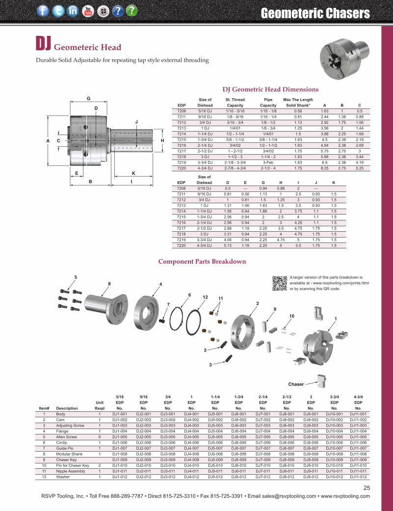
DJ Geometeric HeadDurable Solid Adjustable for repeating tap style external threading
8 4
12
3
3
Chaser
9
10
6
7
5
112
1
A C H
J
D
G
IB
E K
A larger version of this parts breakdown is
available at - www.rsvptooling.com/prints.html
or by scanning this QR code.
DJ Geometric Head DimensionsSize of St. Thread Pipe Max The Length
EDP Diehead Capacity Capacity Solid Shank* A B C
7208 5/16 DJ 1/16 - 5/16 1/16 - 1/8 0.56 1.63 1 0.5
7211 9/16 DJ 1/8 - 9/16 1/16 - 1/4 0.81 2.44 1.38 0.88
7212 3/4 DJ 3/16 - 3/4 1/8 - 1/2 1.13 2.92 1.75 1.06
7213 1 DJ 1/4/01 1/8 - 3/4 1.25 3.56 2 1.44
7214 1-1/4 DJ 1/2 - 1-1/4 1/4/01 1.5 3.88 2.25 1.69
7215 1-3/4 DJ 5/8 - 1-1/2 3/8 - 1-1/4 1.63 4.5 2.38 2.19
7216 2-1/4 DJ 3/4/02 1/2 - 1-1/2 1.63 4.94 2.38 2.69
7217 2-1/2 DJ 1 - 2-1/2 3/4/02 1.75 5.75 2.75 3
7218 3 DJ 1-1/2 - 3 1-1/4 - 2 1.63 5.88 2.38 3.44
7219 3-3/4 DJ 2-1/8 - 3-3/4 3-Feb 1.63 6.5 2.38 4.19
7220 4-3/4 DJ 2-7/8 - 4-3/4 2-1/2 - 4 1.75 8.25 2.75 5.25
Size of
EDP Diehead D E G H I J K
7208 5/16 DJ 0.5 — 0.94 0.88 2 —
7211 9/16 DJ 0.81 0.56 1.13 1 2.5 0.93 1.5
7212 3/4 DJ 1 0.81 1.5 1.25 3 0.93 1.5
7213 1 DJ 1.31 1.06 1.63 1.5 3.5 0.93 1.5
7214 1-1/4 DJ 1.56 0.94 1.88 2 3.75 1.1 1.5
7215 1-3/4 DJ 2.06 0.94 2 2.5 4 1.1 1.5
7216 2-1/4 DJ 2.56 0.94 2 3 4.25 1.1 1.5
7217 2-1/2 DJ 2.88 1.19 2.25 3.5 4.75 1.75 1.5
7218 3 DJ 3.31 0.94 2.25 4 4.75 1.75 1.5
7219 3-3/4 DJ 4.06 0.94 2.25 4.75 5 1.75 1.5
7220 4-3/4 DJ 5.13 1.19 2.25 5 5.5 1.75 1.5
Component Parts Breakdown
5/16 9/16 3/4 1 1-1/4 1-3/4 2-1/4 2-1/2 3 3-3/4 4-3/4
Unit EDP EDP EDP EDP EDP EDP EDP EDP EDP EDP EDP
Item# Description Reqd No. No. No. No. No. No. No. No. No. No. No.
1 Body 1 DJ1-001 DJ2-001 DJ3-001 DJ4-001 DJ5-001 DJ6-001 DJ7-001 DJ8-001 DJ9-001 DJ10-001 DJ11-001
2 Cam 1 DJ1-002 DJ2-002 DJ3-002 DJ4-002 DJ5-002 DJ6-002 DJ7-002 DJ8-002 DJ9-002 DJ10-002 DJ11-002
3 Adjusting Screw 1 DJ1-003 DJ2-003 DJ3-003 DJ4-003 DJ5-003 DJ6-003 DJ7-003 DJ8-003 DJ9-003 DJ10-003 DJ11-003
4 Flange 1 DJ1-004 DJ2-004 DJ3-004 DJ4-004 DJ5-004 DJ6-004 DJ7-004 DJ8-004 DJ9-004 DJ10-004 DJ11-004
5 Allen Screw 6 DJ1-005 DJ2-005 DJ3-005 DJ4-005 DJ5-005 DJ6-005 DJ7-005 DJ8-005 DJ9-005 DJ10-005 DJ11-005
6 Circlip 1 DJ1-006 DJ2-006 DJ3-006 DJ4-006 DJ5-006 DJ6-006 DJ7-006 DJ8-006 DJ9-006 DJ10-006 DJ11-006
7 Guide Pin 1 DJ1-007 DJ2-007 DJ3-007 DJ4-007 DJ5-007 DJ6-007 DJ7-007 DJ8-007 DJ9-007 DJ10-007 DJ11-007
8 Modular Shank 1 DJ1-008 DJ2-008 DJ3-008 DJ4-008 DJ5-008 DJ6-008 DJ7-008 DJ8-008 DJ9-008 DJ10-008 DJ11-008
9 Chaser Key DJ1-009 DJ2-009 DJ3-009 DJ4-009 DJ5-009 DJ6-009 DJ7-009 DJ8-009 DJ9-009 DJ10-009 DJ11-009
10 Pin for Chaser Key 2 DJ1-010 DJ2-010 DJ3-010 DJ4-010 DJ5-010 DJ6-010 DJ7-010 DJ8-010 DJ9-010 DJ10-010 DJ11-010
11 Nipple Assembly 1 DJ1-011 DJ2-011 DJ3-011 DJ4-011 DJ5-011 DJ6-011 DJ7-011 DJ8-011 DJ9-011 DJ10-011 DJ11-011
12 Washer 1 DJ1-012 DJ2-012 DJ3-012 DJ4-012 DJ5-012 DJ6-012 DJ7-012 DJ8-012 DJ9-012 DJ10-012 DJ11-012
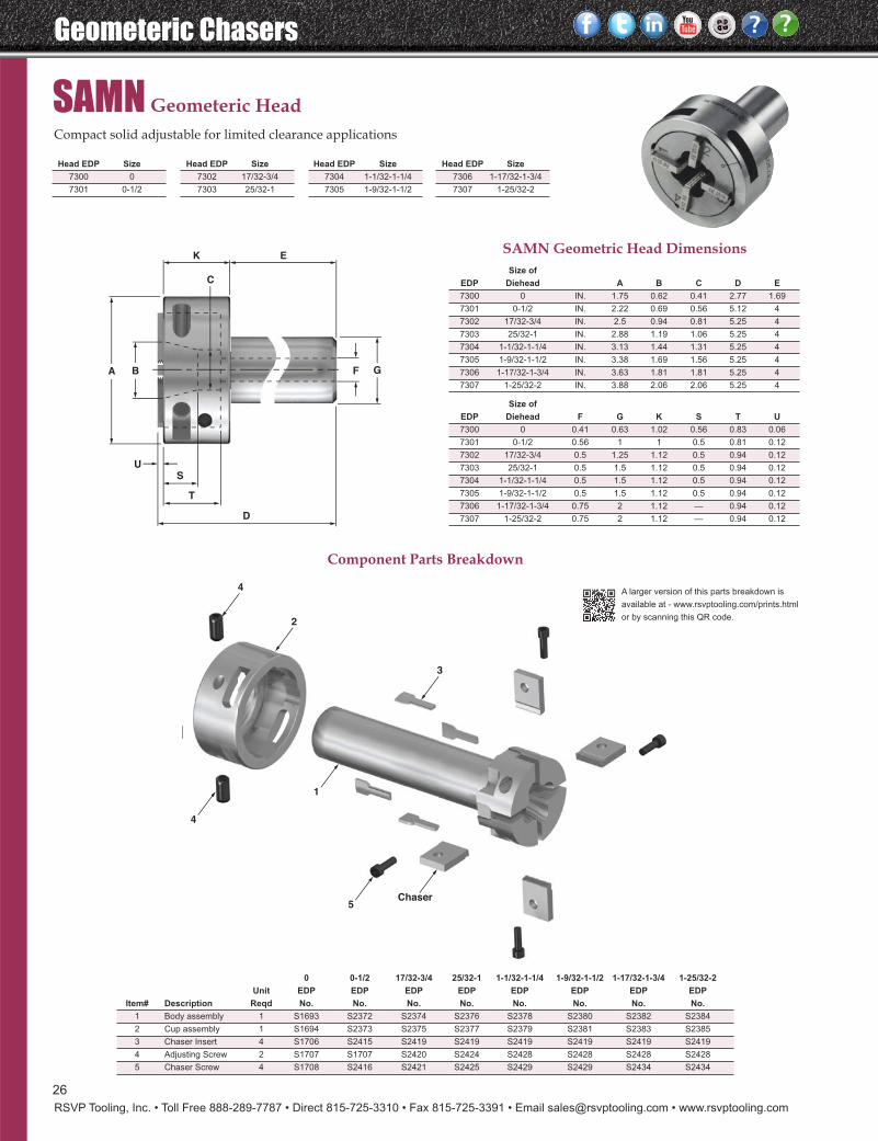
Geometeric Chasers
RSVP Tooling, Inc. • Toll Free 888-289-7787 • Direct 815-725-3310 • Fax 815-725-3391 • Email [email protected] • www.rsvptooling.com
26
SAMN Geometeric HeadCompact solid adjustable for limited clearance applications
3
2
4
4
5Chaser
1
A B F G
K
C
E
SU
T
D
A larger version of this parts breakdown is
available at - www.rsvptooling.com/prints.html
or by scanning this QR code.
SAMN Geometric Head DimensionsSize of
EDP Diehead A B C D E
7300 0 IN. 1.75 0.62 0.41 2.77 1.69
7301 0-1/2 IN. 2.22 0.69 0.56 5.12 4
7302 17/32-3/4 IN. 2.5 0.94 0.81 5.25 4
7303 25/32-1 IN. 2.88 1.19 1.06 5.25 4
7304 1-1/32-1-1/4 IN. 3.13 1.44 1.31 5.25 4
7305 1-9/32-1-1/2 IN. 3.38 1.69 1.56 5.25 4
7306 1-17/32-1-3/4 IN. 3.63 1.81 1.81 5.25 4
7307 1-25/32-2 IN. 3.88 2.06 2.06 5.25 4
Size of
EDP Diehead F G K S T U
7300 0 0.41 0.63 1.02 0.56 0.83 0.06
7301 0-1/2 0.56 1 1 0.5 0.81 0.12
7302 17/32-3/4 0.5 1.25 1.12 0.5 0.94 0.12
7303 25/32-1 0.5 1.5 1.12 0.5 0.94 0.12
7304 1-1/32-1-1/4 0.5 1.5 1.12 0.5 0.94 0.12
7305 1-9/32-1-1/2 0.5 1.5 1.12 0.5 0.94 0.12
7306 1-17/32-1-3/4 0.75 2 1.12 — 0.94 0.12
7307 1-25/32-2 0.75 2 1.12 — 0.94 0.12
Component Parts Breakdown
0 0-1/2 17/32-3/4 25/32-1 1-1/32-1-1/4 1-9/32-1-1/2 1-17/32-1-3/4 1-25/32-2
Unit EDP EDP EDP EDP EDP EDP EDP EDP
Item# Description Reqd No. No. No. No. No. No. No. No.
1 Body assembly 1 S1693 S2372 S2374 S2376 S2378 S2380 S2382 S2384
2 Cup assembly 1 S1694 S2373 S2375 S2377 S2379 S2381 S2383 S2385
3 Chaser Insert 4 S1706 S2415 S2419 S2419 S2419 S2419 S2419 S2419
4 Adjusting Screw 2 S1707 S1707 S2420 S2424 S2428 S2428 S2428 S2428
5 Chaser Screw 4 S1708 S2416 S2421 S2425 S2429 S2429 S2434 S2434
Head EDP Size
7300 0
7301 0-1/2
Head EDP Size
7302 17/32-3/4
7303 25/32-1
Head EDP Size
7304 1-1/32-1-1/4
7305 1-9/32-1-1/2
Head EDP Size
7306 1-17/32-1-3/4
7307 1-25/32-2
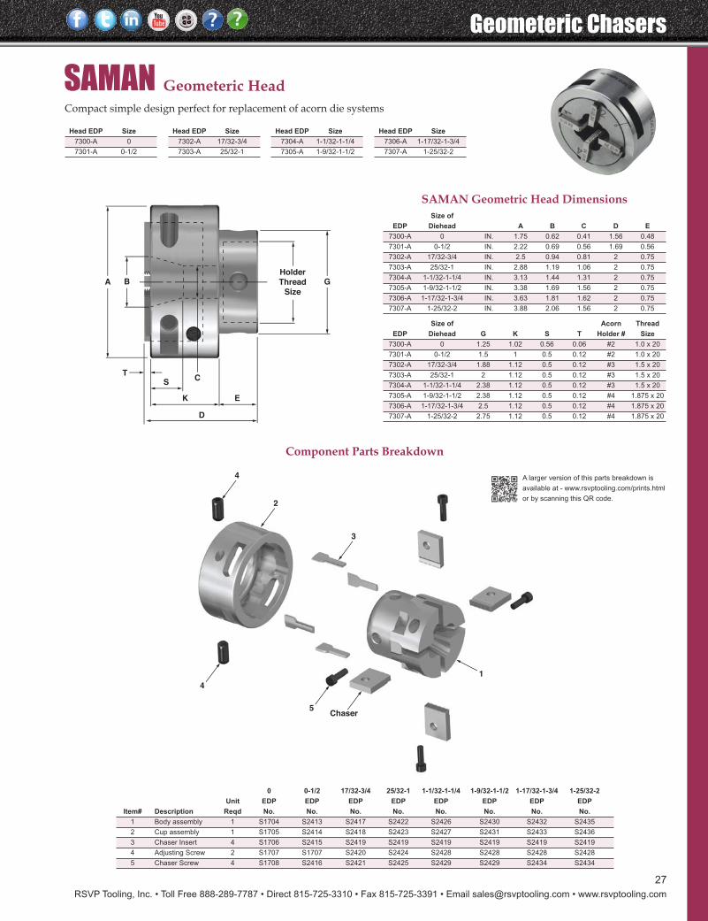
RSVP Tooling, Inc. • Toll Free 888-289-7787 • Direct 815-725-3310 • Fax 815-725-3391 • Email [email protected] • www.rsvptooling.com
Geometeric Chasers
27
SAMAN Geometeric HeadCompact simple design perfect for replacement of acorn die systems
3
2
4
4
5Chaser
1
A BHolder
Thread
Size
G
CS
T
K E
D
A larger version of this parts breakdown is
available at - www.rsvptooling.com/prints.html
or by scanning this QR code.
SAMAN Geometric Head DimensionsSize of
EDP Diehead A B C D E
7300-A 0 IN. 1.75 0.62 0.41 1.56 0.48
7301-A 0-1/2 IN. 2.22 0.69 0.56 1.69 0.56
7302-A 17/32-3/4 IN. 2.5 0.94 0.81 2 0.75
7303-A 25/32-1 IN. 2.88 1.19 1.06 2 0.75
7304-A 1-1/32-1-1/4 IN. 3.13 1.44 1.31 2 0.75
7305-A 1-9/32-1-1/2 IN. 3.38 1.69 1.56 2 0.75
7306-A 1-17/32-1-3/4 IN. 3.63 1.81 1.62 2 0.75
7307-A 1-25/32-2 IN. 3.88 2.06 1.56 2 0.75
Size of Acorn Thread
EDP Diehead G K S T Holder # Size
7300-A 0 1.25 1.02 0.56 0.06 #2 1.0 x 20
7301-A 0-1/2 1.5 1 0.5 0.12 #2 1.0 x 20
7302-A 17/32-3/4 1.88 1.12 0.5 0.12 #3 1.5 x 20
7303-A 25/32-1 2 1.12 0.5 0.12 #3 1.5 x 20
7304-A 1-1/32-1-1/4 2.38 1.12 0.5 0.12 #3 1.5 x 20
7305-A 1-9/32-1-1/2 2.38 1.12 0.5 0.12 #4 1.875 x 20
7306-A 1-17/32-1-3/4 2.5 1.12 0.5 0.12 #4 1.875 x 20
7307-A 1-25/32-2 2.75 1.12 0.5 0.12 #4 1.875 x 20
Component Parts Breakdown
Head EDP Size
7300-A 0
7301-A 0-1/2
Head EDP Size
7302-A 17/32-3/4
7303-A 25/32-1
Head EDP Size
7304-A 1-1/32-1-1/4
7305-A 1-9/32-1-1/2
Head EDP Size
7306-A 1-17/32-1-3/4
7307-A 1-25/32-2
0 0-1/2 17/32-3/4 25/32-1 1-1/32-1-1/4 1-9/32-1-1/2 1-17/32-1-3/4 1-25/32-2
Unit EDP EDP EDP EDP EDP EDP EDP EDP
Item# Description Reqd No. No. No. No. No. No. No. No.
1 Body assembly 1 S1704 S2413 S2417 S2422 S2426 S2430 S2432 S2435
2 Cup assembly 1 S1705 S2414 S2418 S2423 S2427 S2431 S2433 S2436
3 Chaser Insert 4 S1706 S2415 S2419 S2419 S2419 S2419 S2419 S2419
4 Adjusting Screw 2 S1707 S1707 S2420 S2424 S2428 S2428 S2428 S2428
5 Chaser Screw 4 S1708 S2416 S2421 S2425 S2429 S2429 S2434 S2434
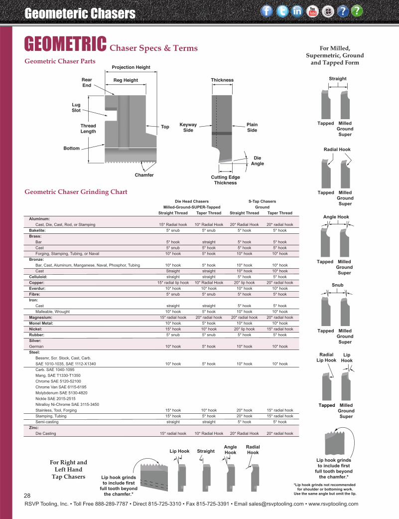
Geometeric Chasers
RSVP Tooling, Inc. • Toll Free 888-289-7787 • Direct 815-725-3310 • Fax 815-725-3391 • Email [email protected] • www.rsvptooling.com
28
GEOMETRIC Chaser Specs & Terms
*Lip hook grinds not recommended
for shoulder or bottoming work.
Use the same angle but omit the lip.
Lip hook grinds
to include first
full tooth beyond
the chamfer.*
Thickness
Die
Angle
Chamfer
Keyway
SideTopThread
Length
Lug
Slot
Rear
End
Bottom
Plain
Side
Cutting Edge
Thickness
Reg Height
Projection Height
Geometric Chaser Parts
Geometric Chaser Grinding Chart
Radial
Hook
Angle
HookStraightLip Hook
Lip hook grinds
to include first
full tooth beyond
the chamfer.*
For Right andLeft Hand
Tap Chasers
Die Head Chasers S-Tap Chasers
Milled-Ground-SUPER-Tapped Ground
Straight Thread Taper Thread Straight Thread Taper Thread
Aluminum:
Cast, Die, Cast, Rod, or Stamping 15* Radial hook 10* Radial Hook 20* Radial Hook 20* radial hook
Bakelite: 5* snub 5* snub 5* hook 5* hook
Brass:
Bar 5* hook straight 5* hook 5* hook
Cast 5* snub 5* hook 5* hook 5* hook
Forging, Stamping, Tubing, or Naval 10* hook 5* hook 10* hook 10* hook
Bronze:
Bar, Cast, Aluminum, Manganese, Naval, Phosphor, Tubing 10* hook 5* hook 10* hook 10* hook
Cast Straight straight 10* hook 10* hook
Celluloid: straight straight 5* hook 5* hook
Copper: 15* radial lip hook 10* Radial Hook 20* lip hook 20* radial hook
Everdur: 10* hook 10* hook 10* hook 10* hook
Fibre: 5* snub 5* snub 5* hook 5* hook
Iron:
Cast straight straight 5* hook 5* hook
Malleable, Wrought 10* hook 5* hook 10* hook 10* hook
Magnesium: 15* radial hook 20* radial hook 20* radial hook 20* radial hook
Monel Metal: 10* hook 5* hook 10* hook 10* hook
Nickel: 15* hook 10* hook 20* lip hook 15* radial hook
Rubber: 5* snub 5* snub 5* hook 5* hook
Silver:
German 10* hook 5* hook 10* hook 10* hook
Steel:
Bessmr, Scr. Stock, Cast, Carb.
SAE 1010-1035, SAE 1112-X1340 10* hook 5* hook 10* hook 10* hook
Carb. SAE 1040-1095
Mang. SAE T1330-T1350
Chrome SAE 5120-52100
Chrome Van SAE 6115-6195
Molybdenum SAE 5130-4820
Nickle SAE 2015-2515
Nitralloy Ni-Chrome SAE 3115-3450
Stainless, Tool, Forging 15* hook 10* hook 20* hook 15* radial hook
Stamping, Tubing 15* hook 5* hook 20* hook 15* radial hook
Semi-casting straight straight 5* hook 5* hook
Zinc:
Die Casting 15* radial hook 10* Radial Hook 20* Radial Hook 20* radial hook
Radial
Lip HookLip
Hook
Tapped Milled
Ground
Super
Snub
Tapped Milled
Ground
Super
Angle Hook
Tapped Milled
Ground
Super
Radial Hook
Tapped Milled
Ground
Super
Straight
Tapped Milled
Ground
Super
For Milled,Supermetric, Ground
and Tapped Form
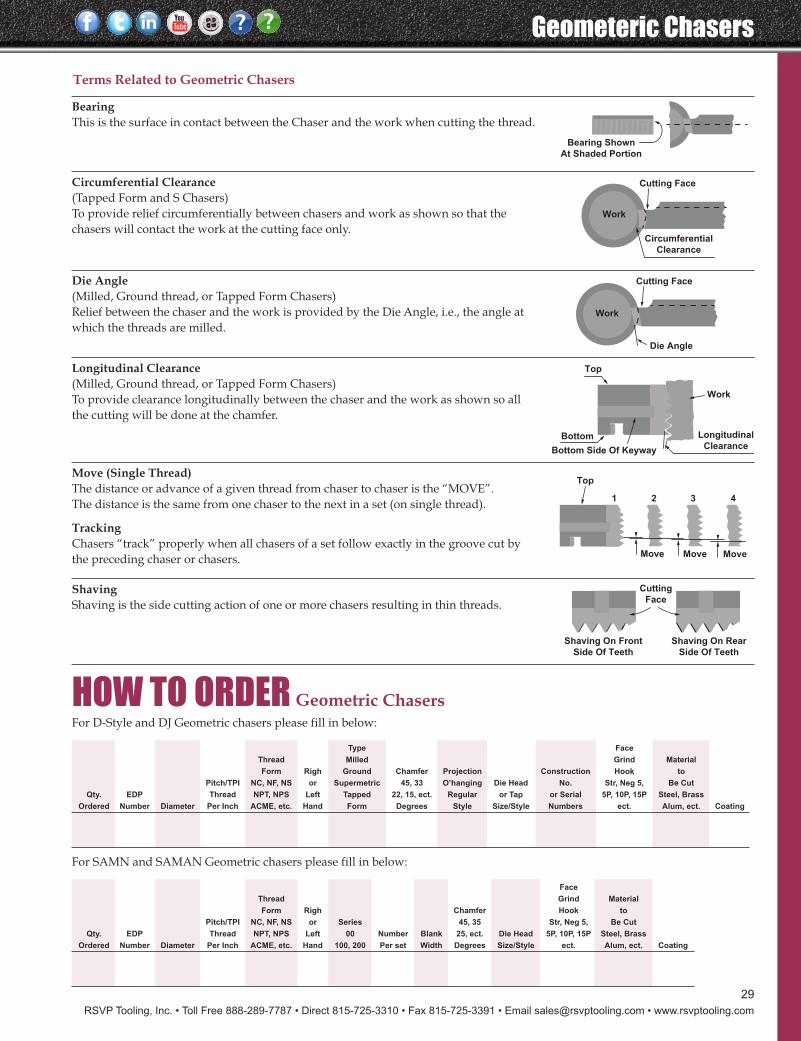
RSVP Tooling, Inc. • Toll Free 888-289-7787 • Direct 815-725-3310 • Fax 815-725-3391 • Email [email protected] • www.rsvptooling.com
29
Geometeric Chasers
Bearing Shown
At Shaded Portion
Cutting Face
Work
Circumferential
Clearance
Work
Cutting Face
Die Angle
Top
Bottom Longitudinal
ClearanceBottom Side Of Keyway
Work
Top
1 2 3 4
Move Move Move
Cutting
Face
Shaving On Front
Side Of Teeth
Shaving On Rear
Side Of Teeth
BearingThis is the surface in contact between the Chaser and the work when cutting the thread.
TrackingChasers “track” properly when all chasers of a set follow exactly in the groove cut bythe preceding chaser or chasers.
Circumferential Clearance(Tapped Form and S Chasers)To provide relief circumferentially between chasers and work as shown so that thechasers will contact the work at the cutting face only.
Die Angle(Milled, Ground thread, or Tapped Form Chasers)Relief between the chaser and the work is provided by the Die Angle, i.e., the angle atwhich the threads are milled.
Longitudinal Clearance(Milled, Ground thread, or Tapped Form Chasers)To provide clearance longitudinally between the chaser and the work as shown so allthe cutting will be done at the chamfer.
Move (Single Thread)The distance or advance of a given thread from chaser to chaser is the “MOVE”.The distance is the same from one chaser to the next in a set (on single thread).
ShavingShaving is the side cutting action of one or more chasers resulting in thin threads.
HOW TO ORDER Geometric Chasers
Type Face
Thread Milled Grind Material
Form Righ Ground Chamfer Projection Construction Hook to
Pitch/TPI NC, NF, NS or Supermetric 45, 33 O’hanging Die Head No. Str, Neg 5, Be Cut
Qty. EDP Thread NPT, NPS Left Tapped 22, 15, ect. Regular or Tap or Serial 5P, 10P, 15P Steel, Brass
Ordered Number Diameter Per Inch ACME, etc. Hand Form Degrees Style Size/Style Numbers ect. Alum, ect. Coating
For D-Style and DJ Geometric chasers please fill in below:
Face
Thread Grind Material
Form Righ Chamfer Hook to
Pitch/TPI NC, NF, NS or Series 45, 35 Str, Neg 5, Be Cut
Qty. EDP Thread NPT, NPS Left 00 Number Blank 25, ect. Die Head 5P, 10P, 15P Steel, Brass
Ordered Number Diameter Per Inch ACME, etc. Hand 100, 200 Per set Width Degrees Size/Style ect. Alum, ect. Coating
For SAMN and SAMAN Geometric chasers please fill in below:
Terms Related to Geometric Chasers
Axial Thread Rolling
RSVP Tooling, Inc. • Toll Free 888-289-7787 • Direct 815-725-3310 • Fax 815-725-3391 • Email [email protected] • www.rsvptooling.com
30
Selecting Thread RollsWhen ordering thread rolls it is important to specify as muchinformation as possible about the rolls and the application sothat the correct rolls may be promptly supplied. The minimumdetails required are as follows:
The full thread specification (e.g. 3/8 - 16 UNC, 7/16 - 20 UNF,1/2 - 14 NPSM, 1/4 - 19 BSP)
The thread rolling head for which the rolls are required (A1, A23, A01 Etc.)
The lead required on the rolls (1K standard short lead, 2Kstandard long lead, or other special lead)
Using the 7/16 - 14 UNC stud example, to be produced usingthe A2 head, the final order would read as follows:
Quantity Description 1 A2 THREAD ROLLING HEAD,
1" DIAMETER SHANK
2 SETS 7/16 - 14 UNC ROLLS WITH 2K LEAD, TO SUIT A2 HEAD
Should there be any doubt about the type of lead required onthe rolls, or the size of head to be used, please provide ourtechnical department with a component drawing so that wemay make our own recommendations. Test samples may beproduced with customer's material on special request.
Selecting The Correct Thread Rolling HeadThere are two main factors that govern the choice of threadrolling head:
1. The thread size has to be within the standard capacity ofthe thread rolling head.
2. There must be sufficient clearance within the machine forthe head to operate.
On pages 34 to 47 the range of axial thread rolling heads isillustrated, showing the outline dimensions and standardthread sizes for each head. Left hand and rotating versions ofthese heads are available in all the standard sizes. Specialhigh-helix heads can also be supplied to accommodate Acmeand multi-start threads.
Example:In order to produce a 7/16 - 14 UNC stud, there is a choicebetween the A1, A2 and A3 heads. This choice may be limitedby the clearance on the machine so it is most important toknow the maximum diameter and projection available. If themaximum diameter that will clear when the machine turretindexes is 3.75", then the A3 head, at 4.60" diameter, is nolonger a viable option. The choice between the A1 or the A2should then be made with consideration given to any otherthreads that may need to be produced on the chosen head.If 7/16 UNC is the maximum thread size required then theA1, with a range of 1/4 UNC up to 7/16 UNC would be therecommended choice. However, if thread sizes above 7/16UNC are required then the A2, with a range of 5/16 UNCup to 5/8 UNC, should be selected. Having selected theappropriate thread rolling head, please specify the requiredshank diameter from the options available.
How To Order
For producing long threads, or threads without run-out restriction,then RSVP axial rolling heads are the ideal selection. Axialheads feed on from the end of the part and require onerevolution of the spindle for each pitch of thread to beproduced. Controlled forward axial motion, either by cam orCNC feed, are recommended although manually operatedlathes can also give excellent results. RSVP axial heads are selfopening and normally require an external closing action toreset them for the next pass. Right hand rolling heads arerequired for rolling right hand threads and the spindledirection must also be right hand. Left hand threads requirecorresponding heads and spindle rotation.
AXIAL Thread RollingRSVP Thread Rolling System Advantages ..............................31Thread Rolling Introduction .....................................................32Applications ................................................................................33A0 - Overview & Components .................................................34A001 - Overview & Components .............................................35A01 - Overview & Components ...............................................36A1 - Overview & Components .................................................37A12 - Overview & Components ................................................38A2 - Overview & Components ..................................................39 A23 - Overview & Components ...............................................40A233400 - Overview & Components ........................................41 A3 - Overview & Components ..................................................42 A34 - Overview & Components ...............................................43 A4 - Overview & Components .................................................44 A45 - Overview & Components ...............................................45 A5 - Overview & Components .................................................46 A56 - Overview & Components ...............................................47Operation...............................................................................48 - 50Problem Solving ..........................................................................51Lead Angles ..........................................................................52 - 54Recommended Blank Diameters........................................55 - 57Rolling Speeds .............................................................................58
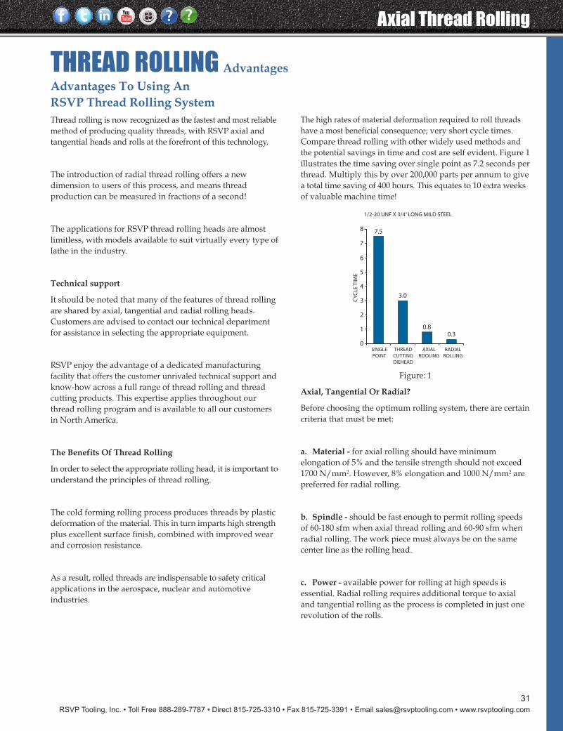
RSVP Tooling, Inc. • Toll Free 888-289-7787 • Direct 815-725-3310 • Fax 815-725-3391 • Email [email protected] • www.rsvptooling.com
31
Axial Thread Rolling
Advantages To Using An RSVP Thread Rolling SystemThread rolling is now recognized as the fastest and most reliablemethod of producing quality threads, with RSVP axial andtangential heads and rolls at the forefront of this technology.
The introduction of radial thread rolling offers a newdimension to users of this process, and means threadproduction can be measured in fractions of a second!
The applications for RSVP thread rolling heads are almostlimitless, with models available to suit virtually every type oflathe in the industry.
Technical support
It should be noted that many of the features of thread rollingare shared by axial, tangential and radial rolling heads.Customers are advised to contact our technical departmentfor assistance in selecting the appropriate equipment.
RSVP enjoy the advantage of a dedicated manufacturingfacility that offers the customer unrivaled technical support andknow-how across a full range of thread rolling and threadcutting products. This expertise applies throughout ourthread rolling program and is available to all our customersin North America.
The Benefits Of Thread Rolling
In order to select the appropriate rolling head, it is important tounderstand the principles of thread rolling.
The cold forming rolling process produces threads by plasticdeformation of the material. This in turn imparts high strengthplus excellent surface finish, combined with improved wearand corrosion resistance.
As a result, rolled threads are indispensable to safety criticalapplications in the aerospace, nuclear and automotiveindustries.
The high rates of material deformation required to roll threadshave a most beneficial consequence; very short cycle times.Compare thread rolling with other widely used methods andthe potential savings in time and cost are self evident. Figure 1illustrates the time saving over single point as 7.2 seconds perthread. Multiply this by over 200,000 parts per annum to givea total time saving of 400 hours. This equates to 10 extra weeksof valuable machine time!
Figure: 1
Axial, Tangential Or Radial?
Before choosing the optimum rolling system, there are certaincriteria that must be met:
a. Material - for axial rolling should have minimumelongation of 5% and the tensile strength should not exceed1700 N/mm2. However, 8% elongation and 1000 N/mm2 arepreferred for radial rolling.
b. Spindle - should be fast enough to permit rolling speedsof 60-180 sfm when axial thread rolling and 60-90 sfm whenradial rolling. The work piece must always be on the samecenter line as the rolling head.
c. Power - available power for rolling at high speeds isessential. Radial rolling requires additional torque to axialand tangential rolling as the process is completed in just onerevolution of the rolls.
THREAD ROLLING Advantages
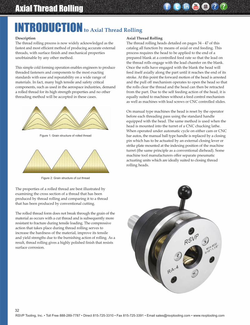
Axial Thread Rolling
RSVP Tooling, Inc. • Toll Free 888-289-7787 • Direct 815-725-3310 • Fax 815-725-3391 • Email [email protected] • www.rsvptooling.com
32
INTRODUCTION to Axial Thread RollingDescriptionThe thread rolling process is now widely acknowledged as thefastest and most efficient method of producing accurate externalthreads, with surface finish and mechanical propertiesunobtainable by any other method.
This simple cold forming operation enables engineers to producethreaded fasteners and components to the most exactingstandards with ease and repeatability on a wide range ofmaterials. In fact, many high tensile and safety criticalcomponents, such as used in the aerospace industries, demanda rolled thread for its high strength properties and no otherthreading method will be accepted in these cases.
Figure 1: Grain structure of rolled thread
Figure 2: Grain structure of cut thread
Axial Thread RollingThe thread rolling heads detailed on pages 34 - 47 of thiscatalog all function by means of axial or end feeding. Thisprocess requires the head to be applied to the end of aprepared blank at a controlled feed rate so that the lead onthe thread rolls engage with the lead chamfer on the blank.Once the rolls have engaged with the blank the head willfeed itself axially along the part until it reaches the end of itsstroke. At this point the forward motion of the head is arrestedand the pull off mechanism operates to open the head so thatthe rolls clear the thread and the head can then be retractedfrom the part. Due to the self feeding action of the head, it isequally suited to machines without a feed control mechanismas well as machines with lead screws or CNC controlled slides.
On manual type machines the head is reset by the operatorbefore each threading pass using the standard handleequipped with the head. The same method is used when thehead is mounted into the turret of a CNC chucking lathe.When operated under automatic cycle on either cam or CNCbar autos, the manual ball type handle is replaced by a closingpin which has to be actuated by an external closing lever orstrike plate mounted at the indexing position of the machineturret (the same principle as a conventional diehead). Somemachine tool manufacturers offer separate pneumaticactuating units which are ideally suited to closing threadrolling heads.
The properties of a rolled thread are best illustrated byexamining the cross section of a thread that has beenproduced by thread rolling and comparing it to a threadthat has been produced by conventional cutting.
The rolled thread form does not break through the grain of thematerial as occurs with a cut thread and is subsequently moreresistant to fracture during tensile loading. The compressiveaction that takes place during thread rolling serves toincrease the hardness of the material, improve its tensileand yield strengths due to the burnishing action of rolling. As aresult, thread rolling gives a highly polished finish that resistssurface corrosion.
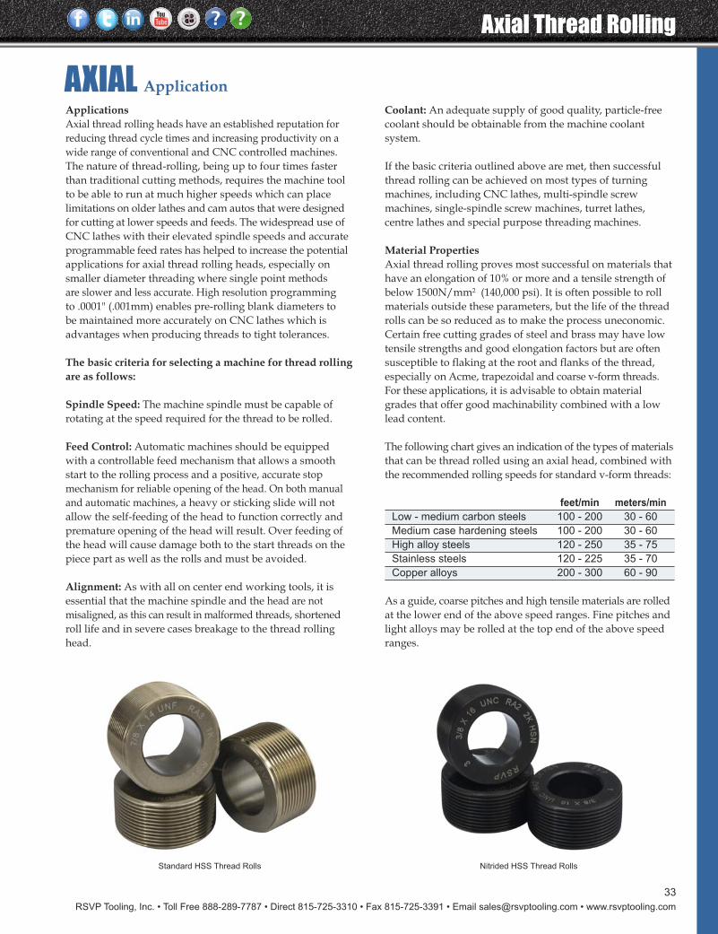
RSVP Tooling, Inc. • Toll Free 888-289-7787 • Direct 815-725-3310 • Fax 815-725-3391 • Email [email protected] • www.rsvptooling.com
Axial Thread Rolling
33
AXIAL ApplicationApplicationsAxial thread rolling heads have an established reputation forreducing thread cycle times and increasing productivity on awide range of conventional and CNC controlled machines.The nature of thread-rolling, being up to four times fasterthan traditional cutting methods, requires the machine toolto be able to run at much higher speeds which can placelimitations on older lathes and cam autos that were designedfor cutting at lower speeds and feeds. The widespread use ofCNC lathes with their elevated spindle speeds and accurateprogrammable feed rates has helped to increase the potentialapplications for axial thread rolling heads, especially onsmaller diameter threading where single point methodsare slower and less accurate. High resolution programmingto .0001" (.001mm) enables pre-rolling blank diameters tobe maintained more accurately on CNC lathes which isadvantages when producing threads to tight tolerances.
The basic criteria for selecting a machine for thread rollingare as follows:
Spindle Speed: The machine spindle must be capable ofrotating at the speed required for the thread to be rolled.
Feed Control: Automatic machines should be equippedwith a controllable feed mechanism that allows a smoothstart to the rolling process and a positive, accurate stopmechanism for reliable opening of the head. On both manualand automatic machines, a heavy or sticking slide will notallow the self-feeding of the head to function correctly andpremature opening of the head will result. Over feeding ofthe head will cause damage both to the start threads on thepiece part as well as the rolls and must be avoided.
Alignment: As with all on center end working tools, it isessential that the machine spindle and the head are not misaligned, as this can result in malformed threads, shortenedroll life and in severe cases breakage to the thread rollinghead.
Coolant: An adequate supply of good quality, particle-freecoolant should be obtainable from the machine coolant system.
If the basic criteria outlined above are met, then successfulthread rolling can be achieved on most types of turningmachines, including CNC lathes, multi-spindle screwmachines, single-spindle screw machines, turret lathes, centre lathes and special purpose threading machines.
Material PropertiesAxial thread rolling proves most successful on materials thathave an elongation of 10% or more and a tensile strength ofbelow 1500N/mm2 (140,000 psi). It is often possible to rollmaterials outside these parameters, but the life of the threadrolls can be so reduced as to make the process uneconomic.Certain free cutting grades of steel and brass may have lowtensile strengths and good elongation factors but are oftensusceptible to flaking at the root and flanks of the thread,especially on Acme, trapezoidal and coarse v-form threads.For these applications, it is advisable to obtain materialgrades that offer good machinability combined with a lowlead content.
The following chart gives an indication of the types of materialsthat can be thread rolled using an axial head, combined withthe recommended rolling speeds for standard v-form threads:
feet/min meters/min
Low - medium carbon steels 100 - 200 30 - 60
Medium case hardening steels 100 - 200 30 - 60
High alloy steels 120 - 250 35 - 75
Stainless steels 120 - 225 35 - 70
Copper alloys 200 - 300 60 - 90
As a guide, coarse pitches and high tensile materials are rolledat the lower end of the above speed ranges. Fine pitches andlight alloys may be rolled at the top end of the above speedranges.
Standard HSS Thread Rolls Nitrided HSS Thread Rolls
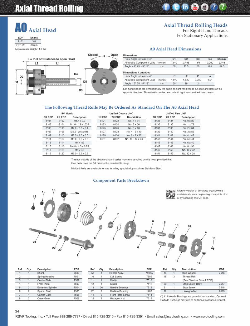
Axial Thread Rolling
RSVP Tooling, Inc. • Toll Free 888-289-7787 • Direct 815-725-3310 • Fax 815-725-3391 • Email [email protected] • www.rsvptooling.com
34
ISO Metric
1K EDP 2K EDP Description
8101 8102 M1.4 x 0.3
8103 8104 M1.6 - 1.8 x .035
8105 8106 M2.0 - 2.3 x 0.4
8107 8108 M2.2 - 2.6 x 045
8109 8110 M2.5 - 3.0 x 0.5
8111 8112 M3.0 - 3.5 x 0.6
8113 8114 M4 x .07
8115 8116 M4.0 - 4.5 x 0.75
8117 8118 M5 x 0.8
8119 8120 M5.0 - 5.5 x 0.9
Unified Coarse UNC
1K EDP 2K EDP Description
8121 8122 No. 1 x 64
8123 8124 No. 2 x 56
8125 8126 No. 3 x 48
8127 8128 No. 4 - 5 x 40
8129 8130 No. 6 - 8 x 32
8131 8132 No. 10 - 12 x 24
Unified Fine UNF
1K EDP 2K EDP Description
8133 8134 No. 0 x 80
8135 8136 No. 1 x 72
8137 8138 No. 2 x 64
8139 8140 No. 3 x 56
8141 8142 No. 4 x 48
8143 8144 No. 5 x 44
8145 8146 No. 6 x 40
8147 8148 No. 8 x 36
8149 8150 No. 10 x 32
8151 8152 No. 12 x 28
A0 Axial HeadAxial Thread Rolling Heads
For Right Hand ThreadsFor Stationary Applications
L1L2
P = Pull off Distance to open Head
D2D4
D3
D5
aClosed Open
D1
Dimensions
Helix Angle in Head = 4º D1 D2 D3 D4 D5 max
Allowable Component Lead inches 1.970 0.453 3/4 0.260 2.146
Angle = 2º 25' - 5º 12' mm 50 11.5 20 6.5 54.5
Dimensions Continued
Helix Angle in Head = 4º L1 L2 P a
Allowable Component Lead inches 1.970 1.520 0.080 50º
Angle = 2º 25' - 5º 12' mm 50 39 2
13
118
6
5
21
2220
1
24
18
13
14
18
6
3
5
7
810
12
9A16
15
15
14
Component Parts Breakdown
Ref Qty Description EDP
16 1 Ring Washer 7516
18 3 Thread Roll
(See Chart for Size & EDP)
20 1 Stop Screw Body 7517
21 1 Stop Screw 7518
22 1 Hexagon Nut 7519
Ref Qty Description EDP
1 1 Shank 7500
2 1 Spring Housing 7501
3 1 Center Plate 7502
4 1 Front Plate 7503
5 2 Eccentric Spindle 7504
6 2 Spacer Stud 7505
7 1 Center Gear 7506
8 2 Outer Gear 7507
Ref Qty Description EDP
9A 1 Handle Assy. 7508A
10 1 Coil Spring 7509
11 1 Circlip 7510
12 1 Circlip 7511
13 36 Needle Bearings 7512
13* 2 Carbide Bushing 1466
14 2 Front Plate Screw 7514
15 2 Hexagon Nut 7515(*) #13 Needle Bearings are provided as standard. Optional
Carbide Bushings provided at additional cost upon request.
EDP Shank
7101 3/4
7101-20 20mm
The Following Thread Rolls May Be Ordered As Standard On The A0 Axial Head
A0 Axial Head Dimensions
Left hand heads are dimensionally the same as right hand heads but open and close on the
opposite direction. Thread rolls can be used in both right hand and left hand heads.
Threads outside of the above standard series may also be rolled on this head provided that
their helix does not fall outside the permissible range.
Nitrided Rolls are available for use in rolling special alloys such as Stainless Steel.
A larger version of this parts breakdown is
available at - www.rsvptooling.com/prints.html
or by scanning this QR code.
Approximate Weight: 1.2 lbs
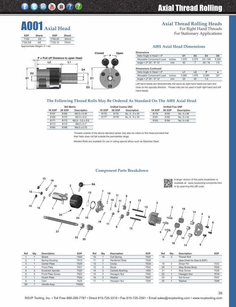
RSVP Tooling, Inc. • Toll Free 888-289-7787 • Direct 815-725-3310 • Fax 815-725-3391 • Email [email protected] • www.rsvptooling.com
Axial Thread Rolling
35
Ref Qty Description EDP
18 3 Thread Roll
(See Chart for Size & EDP)
19 3 Shear Pin 7533
20 1 Stop Screw Body 7535
21 1 Stop Screw 7536
22 1 Hexagon Nut 7519
24 2 Set Screw 7547
25 1 Washer 7548
Ref Qty Description EDP
1 1 Shank 7544
2 1 Spring Housing 7513
3 1 Center Plate 7520
4 1 Front Plate 7521
5 3 Eccentric Spindle 7522
6 3 Front Plate Screw 7523
7 1 Clutch Plate 7524
8 3 Cam 7525
9A 1 Handle Assy. 7546A
Ref Qty Description EDP
10 1 Coil Spring 7545
11 3 Hardened Slide 7528
12 1 Circlip 7529
13 3 Studs 7542
14 3 Carbide Bushing 1453
15 3 Hexagon Nut 7543
16 3 Washer 7537
17 1 Hexagon Nut 7549
A001 Axial HeadAxial Thread Rolling Heads
For Right Hand ThreadsFor Stationary Applications
2424 10
1911
813
5
5
18
18
14
14 6
1
21
2220
1615
15
16
1615
197
19
11
11
8
813
13
3
518
144
6
6
12
9A2
ISO Metric
1K EDP 2K EDP Description
8167 8168 M2.6 x 0.45
8169 8170 M3.0 x 0.5
8171 8172 M3.0 - 3.5 x 0.6
8173 8174 M4.0 x 0.7
8165 8166 M4.0 x 0.75
Unified Coarse UNC
1K EDP 2K EDP Description
8175 8176 No. 4 - 5 x 40
8177 8178 No. 6 - 8 x 32
Unified Fine UNF
1K EDP 2K EDP Description
8179 8180 No. 4 x 48
8181 8182 No. 5 x 44
8183 8184 No. 6 x 40
EDP Shank
7102 3/4
7102-5/8 5/8
EDP Shank
7102-20 20mm
7102-16 16mm
The Following Thread Rolls May Be Ordered As Standard On The A001 Axial Head
Dimensions
Helix Angle in Head = 4º D1 D2 D3 D4
Allowable Component Lead inches 1.575 0.275 3/4 / 5/8 0.295
Angle = 2º 25' - 5º 12' mm 40 7 20 / 16 7.5
Dimensions Continued
Helix Angle in Head = 4º L1 L2 P a
Allowable Component Lead inches 0.985 1.575 0.060 32º
Angle = 2º 25' - 5º 12' mm 25 40 1.5
A001 Axial Head Dimensions
Component Parts Breakdown
Left hand heads are dimensionally the same as right hand heads but open and
close on the opposite direction. Thread rolls can be used in both right hand and left
hand heads.
Threads outside of the above standard series may also be rolled on this head provided that
their helix does not fall outside the permissible range.
Nitrided Rolls are available for use in rolling special alloys such as Stainless Steel.
L1L2
P = Pull off Distance to open Head
D2
D4
D3
D1
aClosed Open
D1
A larger version of this parts breakdown is
available at - www.rsvptooling.com/prints.html
or by scanning this QR code.
Approximate Weight: 0.1 lbs
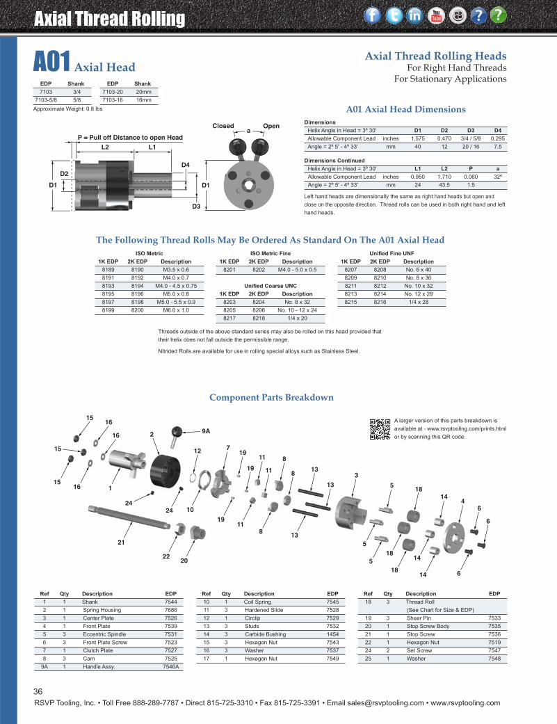
Axial Thread Rolling
RSVP Tooling, Inc. • Toll Free 888-289-7787 • Direct 815-725-3310 • Fax 815-725-3391 • Email [email protected] • www.rsvptooling.com
A01 Axial HeadAxial Thread Rolling Heads
For Right Hand ThreadsFor Stationary Applications
36
Component Parts Breakdown
2424 10
1911
813
5
5
18
18
14
14 6
1
21
2220
1615
15
16
1615
197
19
11
11
8
813
13
3
518
144
6
6
12
9A2
Ref Qty Description EDP
18 3 Thread Roll
(See Chart for Size & EDP)
19 3 Shear Pin 7533
20 1 Stop Screw Body 7535
21 1 Stop Screw 7536
22 1 Hexagon Nut 7519
24 2 Set Screw 7547
25 1 Washer 7548
Ref Qty Description EDP
1 1 Shank 7544
2 1 Spring Housing 7686
3 1 Center Plate 7526
4 1 Front Plate 7539
5 3 Eccentric Spindle 7531
6 3 Front Plate Screw 7523
7 1 Clutch Plate 7527
8 3 Cam 7525
9A 1 Handle Assy. 7546A
Ref Qty Description EDP
10 1 Coil Spring 7545
11 3 Hardened Slide 7528
12 1 Circlip 7529
13 3 Studs 7532
14 3 Carbide Bushing 1454
15 3 Hexagon Nut 7543
16 3 Washer 7537
17 1 Hexagon Nut 7549
ISO Metric
1K EDP 2K EDP Description
8189 8190 M3.5 x 0.6
8191 8192 M4.0 x 0.7
8193 8194 M4.0 - 4.5 x 0.75
8195 8196 M5.0 x 0.8
8197 8198 M5.0 - 5.5 x 0.9
8199 8200 M6.0 x 1.0
ISO Metric Fine
1K EDP 2K EDP Description
8201 8202 M4.0 - 5.0 x 0.5
Unified Coarse UNC
1K EDP 2K EDP Description
8203 8204 No. 8 x 32
8205 8206 No. 10 - 12 x 24
8217 8218 1/4 x 20
Unified Fine UNF
1K EDP 2K EDP Description
8207 8208 No. 6 x 40
8209 8210 No. 8 x 36
8211 8212 No. 10 x 32
8213 8214 No. 12 x 28
8215 8216 1/4 x 28
Dimensions
Helix Angle in Head = 3º 30' D1 D2 D3 D4
Allowable Component Lead inches 1.575 0.470 3/4 / 5/8 0.295
Angle = 2º 5' - 4º 33' mm 40 12 20 / 16 7.5
Dimensions Continued
Helix Angle in Head = 3º 30' L1 L2 P a
Allowable Component Lead inches 0.950 1.710 0.060 32º
Angle = 2º 5' - 4º 33' mm 24 43.5 1.5
EDP Shank
7103 3/4
7103-5/8 5/8
EDP Shank
7103-20 20mm
7103-16 16mm
The Following Thread Rolls May Be Ordered As Standard On The A01 Axial Head
A01 Axial Head Dimensions
Left hand heads are dimensionally the same as right hand heads but open and
close on the opposite direction. Thread rolls can be used in both right hand and left
hand heads.
Threads outside of the above standard series may also be rolled on this head provided that
their helix does not fall outside the permissible range.
Nitrided Rolls are available for use in rolling special alloys such as Stainless Steel.
L1L2
P = Pull off Distance to open Head
D2
D4
D3
D1
aClosed Open
D1
A larger version of this parts breakdown is
available at - www.rsvptooling.com/prints.html
or by scanning this QR code.
Approximate Weight: 0.8 lbs
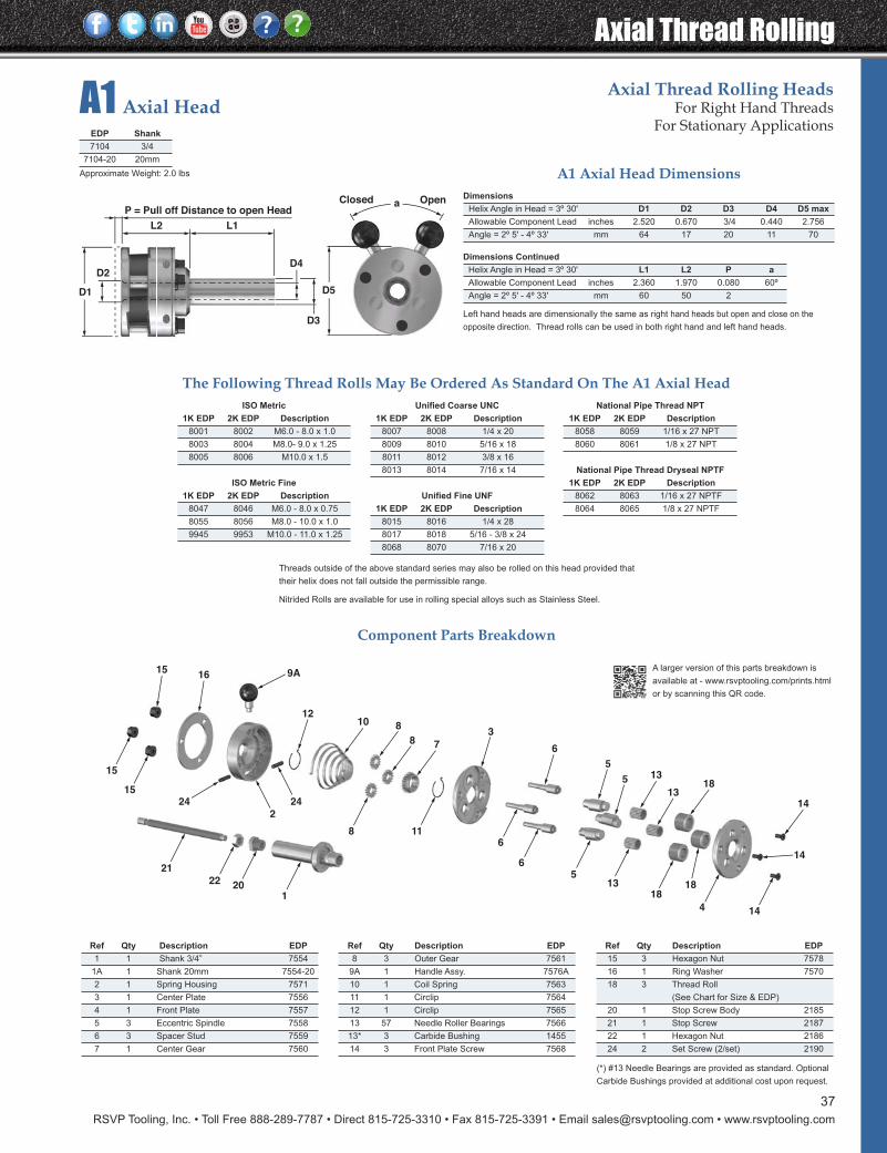
RSVP Tooling, Inc. • Toll Free 888-289-7787 • Direct 815-725-3310 • Fax 815-725-3391 • Email [email protected] • www.rsvptooling.com
Axial Thread Rolling
37
A1 Axial HeadAxial Thread Rolling Heads
For Right Hand ThreadsFor Stationary Applications
6
118
24 24
2
6
521
22 201
15
15
18
4
1818
13
14
13
135
6
3
5
78
81012
1615 9A
14
14
Dimensions
Helix Angle in Head = 3º 30' D1 D2 D3 D4 D5 max
Allowable Component Lead inches 2.520 0.670 3/4 0.440 2.756
Angle = 2º 5' - 4º 33' mm 64 17 20 11 70
Dimensions Continued
Helix Angle in Head = 3º 30' L1 L2 P a
Allowable Component Lead inches 2.360 1.970 0.080 60º
Angle = 2º 5' - 4º 33' mm 60 50 2
Component Parts Breakdown
Ref Qty Description EDP
15 3 Hexagon Nut 7578
16 1 Ring Washer 7570
18 3 Thread Roll
(See Chart for Size & EDP)
20 1 Stop Screw Body 2185
21 1 Stop Screw 2187
22 1 Hexagon Nut 2186
24 2 Set Screw (2/set) 2190
Ref Qty Description EDP
1 1 Shank 3/4” 7554
1A 1 Shank 20mm 7554-20
2 1 Spring Housing 7571
3 1 Center Plate 7556
4 1 Front Plate 7557
5 3 Eccentric Spindle 7558
6 3 Spacer Stud 7559
7 1 Center Gear 7560
Ref Qty Description EDP
8 3 Outer Gear 7561
9A 1 Handle Assy. 7576A
10 1 Coil Spring 7563
11 1 Circlip 7564
12 1 Circlip 7565
13 57 Needle Roller Bearings 7566
13* 3 Carbide Bushing 1455
14 3 Front Plate Screw 7568
(*) #13 Needle Bearings are provided as standard. Optional
Carbide Bushings provided at additional cost upon request.
EDP Shank
7104 3/4
7104-20 20mm
The Following Thread Rolls May Be Ordered As Standard On The A1 Axial Head
A1 Axial Head Dimensions
ISO Metric
1K EDP 2K EDP Description
8001 8002 M6.0 - 8.0 x 1.0
8003 8004 M8.0- 9.0 x 1.25
8005 8006 M10.0 x 1.5
ISO Metric Fine
1K EDP 2K EDP Description
8047 8046 M6.0 - 8.0 x 0.75
8055 8056 M8.0 - 10.0 x 1.0
9945 9953 M10.0 - 11.0 x 1.25
Unified Coarse UNC
1K EDP 2K EDP Description
8007 8008 1/4 x 20
8009 8010 5/16 x 18
8011 8012 3/8 x 16
8013 8014 7/16 x 14
Unified Fine UNF
1K EDP 2K EDP Description
8015 8016 1/4 x 28
8017 8018 5/16 - 3/8 x 24
8068 8070 7/16 x 20
National Pipe Thread NPT
1K EDP 2K EDP Description
8058 8059 1/16 x 27 NPT
8060 8061 1/8 x 27 NPT
National Pipe Thread Dryseal NPTF
1K EDP 2K EDP Description
8062 8063 1/16 x 27 NPTF
8064 8065 1/8 x 27 NPTF
Left hand heads are dimensionally the same as right hand heads but open and close on the
opposite direction. Thread rolls can be used in both right hand and left hand heads.
Threads outside of the above standard series may also be rolled on this head provided that
their helix does not fall outside the permissible range.
Nitrided Rolls are available for use in rolling special alloys such as Stainless Steel.
L1L2
P = Pull off Distance to open Head
D2D4
D3
D5
aClosed Open
D1
A larger version of this parts breakdown is
available at - www.rsvptooling.com/prints.html
or by scanning this QR code.
Approximate Weight: 2.0 lbs
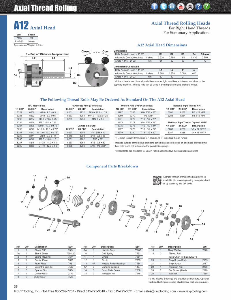
Axial Thread Rolling
RSVP Tooling, Inc. • Toll Free 888-289-7787 • Direct 815-725-3310 • Fax 815-725-3391 • Email [email protected] • www.rsvptooling.com
A12 Axial HeadAxial Thread Rolling Heads
For Right Hand ThreadsFor Stationary Applications
118
24 24
2
6
6
521
22 201
15
15
18
4
1818
1325
14
13
13
5
6
3
525
25
78
810
12
1615
9A
14
14
38
Dimensions
Helix Angle in Head = 1º 50' D1 D2 D3 D4 D5 max
Allowable Component Lead inches 2.520 0.790 3/4 0.430 2.756
Angle = 1º 5' - 2º 23' mm 64 20 20 11 70
Dimensions Continued
Helix Angle in Head = 1º 50' L1 L2 P a
Allowable Component Lead inches 2.360 1.970 0.080 60º
Angle = 1º 5' - 2º 23' mm 60 50 2
Component Parts Breakdown
Ref Qty Description EDP
16 1 Ring Washer 7570
18 3 Thread Roll
(See Chart for Size & EDP)
20 1 Stop Screw Body 2185
21 1 Stop Screw 2187
22 1 Hexagon Nut 2186
24 2 Set Screw (2/set) 2190
25 3 Washer 7585
Ref Qty Description EDP
1 1 Shank 3/4” 7554
1A 1 Shank 20mm 7554-20
2 1 Spring Housing 7571
3 1 Center Plate 7610
4 1 Front Plate 7581
5 3 Eccentric Spindle 7580
6 3 Spacer Stud 7654
7 1 Center Gear 2177
8 3 Outer Gear 7579
Ref Qty Description EDP
9A 1 Handle Assy. 7576A
10 1 Coil Spring 7563
11 1 Circlip 7564
12 1 Circlip 7565
13 57 Needle Roller Bearings 7584
13* 3 Carbide Bushing 1467
14 3 Front Plate Screw 7568
15 3 Hexagon Nut 7578
(*) #13 Needle Bearings are provided as standard. Optional
Carbide Bushings provided at additional cost upon request.
EDP Shank
7105 3/4
7105-20 20mm
The Following Thread Rolls May Be Ordered As Standard On The A12 Axial Head
A12 Axial Head Dimensions
ISO Metric Fine
1K EDP 2K EDP Description
8229 8230 M6.0 - 7.0 x 0.5
8231 8232 M7.0 - 8.0 x 0.5
8233 8234 M6.0 x 7.0 x 0.75
8235 8236 M8.0 - 9.0 x 0.75
8237 8238 M9.0 - 10.0 x 0.75
8239 8240 M10.0 - 11.0 x 0.75*
8241 8242 M11.0 - 12.0 x 0.75*
8243 8244 M8.0 - 9.0 x 1.0
8245 8246 M9.0 - 10.0 x 1.0
8247 8248 M10.0 - 11.0 x 1.0
8249 8250 M11.0 - 12.0 x 1.0
Unified Fine UNF (Continued)
1K EDP 2K EDP Description
8267 8268 3/8 - 7/16 x 28*
8269 8270 1/2 x 28*
8271 8272 7/16 - 1/2 x 26*
8273 8274 3/8 - 7/16 x 24*
8275 8276 7/16 - 1/2 x 24*
8277 8278 7/16 - 1/2 x 22*
8279 8280 7/16 - 1/2 x 20*
National Pipe Thread NPT
1K EDP 2K EDP Description
8281 8282 1/8 x 27 NPT
8283 8284 1/4 x 18 NPT
National Pipe Thread Dryseal NPTF
1K EDP 2K EDP Description
8285 8286 1/8 x 27 NPTF
8287 8288 1/4 x 18 NPTF
ISO Metric Fine (Continued)
1K EDP 2K EDP Description
8251 8252 M10 - 11.0 x 1.25
8253 8254 M11.0 - 12.0 x 1.25
8255 8256 M12.0 x 1.5
Unified Fine UNF
1K EDP 2K EDP Description
8257 8258 1/4 - 5/16 x 40
8259 8260 5/16 - 3/8 x 36
8261 8262 7/16 x 36*
8263 8264 5/16 - 3/8 x 32
8265 8266 7/16 - 1/2 x 32*
Left hand heads are dimensionally the same as right hand heads but open and close on the
opposite direction. Thread rolls can be used in both right hand and left hand heads.
(*) Limited to short threads up to 14mm (0.551”) including thread runout
Threads outside of the above standard series may also be rolled on this head provided that
their helix does not fall outside the permissible range.
Nitrided Rolls are available for use in rolling special alloys such as Stainless Steel.
L1L2
P = Pull off Distance to open Head
D2D4
D3
D5
aClosed Open
D1
A larger version of this parts breakdown is
available at - www.rsvptooling.com/prints.html
or by scanning this QR code.
Approximate Weight: 2.0 lbs
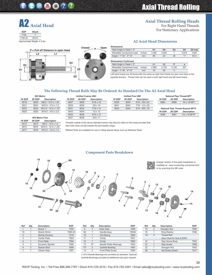
RSVP Tooling, Inc. • Toll Free 888-289-7787 • Direct 815-725-3310 • Fax 815-725-3391 • Email [email protected] • www.rsvptooling.com
Axial Thread Rolling
39
A2 Axial HeadAxial Thread Rolling Heads
For Right Hand ThreadsFor Stationary Applications
6
118
24 24
2
6
521
22 201
15
15
18
4
1818
13
14
13
135
6
3
5
78
81012
1615 9A
14
14
Dimensions
Helix Angle in Head = 3º D1 D2 D3 D4 D5 max
Allowable Component Lead inches 3.460 0.940 1 0.670 3.681
Angle = 1º 50' - 4º 15' mm 88 24 25 17 93.5
Dimensions Continued
Helix Angle in Head = 3º L1 L2 P a
Allowable Component Lead inches 2.990 2.720 0.120 60º
Angle = 1º 50' - 4º 15' mm 76 69 3
Component Parts Breakdown
Ref Qty Description EDP
15 3 Hexagon Nut 7606
16 1 Ring Washer 7596
18 3 Thread Roll
(See Chart for Size & EDP)
20 1 Stop Screw Body 7592
21 1 Stop Screw 7599
22 1 Hexagon Nut 7602
24 2 Set Screw (2/set) 7311
Ref Qty Description EDP
1 1 Shank 1” 7590
1A 1 Shank 25mm 7590-25
2 1 Spring Housing 7310
3 1 Center Plate 7593
4 1 Front Plate 7594
5 3 Eccentric Spindle 7595
6 3 Spacer Stud 7609
7 1 Center Gear 7597
Ref Qty Description EDP
8 3 Outer Gear 7598
9A 1 Handle Assy. 7604A
10 1 Coil Spring 7600
11 1 Circlip 7601
12 1 Circlip 7683
13 57 Needle Roller Bearings 7603
13* 3 Carbide Bushing 1461
14 3 Front Plate Screw 7605
(*) #13 Needle Bearings are provided as standard. Optional
Carbide Bushings provided at additional cost upon request.
EDP Shank
7106 1”
7106-25 25mm
The Following Thread Rolls May Be Ordered As Standard On The A2 Axial Head
A2 Axial Head Dimensions
ISO Metric
1K EDP 2K EDP Description
8019 8020 M8.0 - 10.0 x 1.25
8021 8022 M10.0 - 12.0 x 1.5
8023 8024 M12.0 - 14.0 x 1.75
8025 8026 M14.0 - 16.0 x 2.0
ISO Metric Fine
1K EDP 2K EDP Description
8073 8074 M8.0 - 10.0 x 1.0
8075 8076 M10.0 - 12.0 x 1.25
8077 8078 M12.0 - 14.0 x 1.5
Unified Fine UNF
1K EDP 2K EDP Description
8039 8040 5/16 - 3/8 x 24
8041 8042 7/16 - 1/2 x 20
8043 8044 9/16 - 5/8 x 18
National Pipe Thread NPT
1K EDP 2K EDP Description
8084 8085 1/4 x 18 NPT
National Pipe Thread Dryseal NPTF
1K EDP 2K EDP Description
8086 8087 1/4 x 18 NPTF
Unified Coarse UNC
1K EDP 2K EDP Description
8027 8028 5/16 x 18
8029 8030 3/8 x 16
8031 8032 7/16 x 14
8033 8034 1/2 x 13
8035 8036 9/16 x 12
8037 8038 5/8 x 11
Left hand heads are dimensionally the same as right hand heads but open and close on the
opposite direction. Thread rolls can be used in both right hand and left hand heads.
Threads outside of the above standard series may also be rolled on this head provided that
their helix does not fall outside the permissible range.
Nitrided Rolls are available for use in rolling special alloys such as Stainless Steel.
L1L2
P = Pull off Distance to open Head
D2D4
D3
D5
aClosed Open
D1
A larger version of this parts breakdown is
available at - www.rsvptooling.com/prints.html
or by scanning this QR code.
Approximate Weight: 4.2 lbs
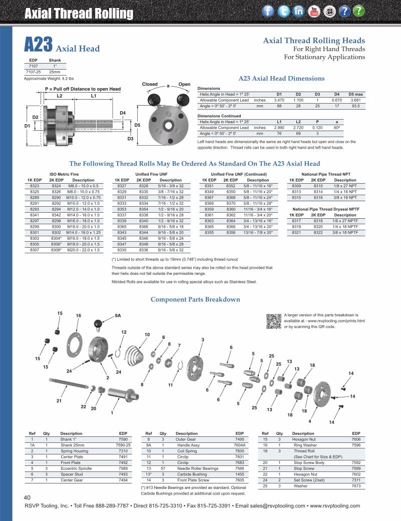
Axial Thread Rolling
RSVP Tooling, Inc. • Toll Free 888-289-7787 • Direct 815-725-3310 • Fax 815-725-3391 • Email [email protected] • www.rsvptooling.com
A23 Axial HeadAxial Thread Rolling Heads
For Right Hand ThreadsFor Stationary Applications
118
24 24
2
6
6
521
22 201
15
15
18
4
1818
1325
14
13
13
5
6
3
525
25
78
810
12
1615
9A
14
14
Dimensions
Helix Angle in Head = 1º 25' D1 D2 D3 D4 D5 max
Allowable Component Lead inches 3.470 1.100 1 0.670 3.681
Angle = 0º 50' - 2º 0' mm 88 28 25 17 93.5
Dimensions Continued
Helix Angle in Head = 1º 25' L1 L2 P a
Allowable Component Lead inches 2.990 2.720 0.120 60º
Angle = 0º 50' - 2º 0' mm 76 69 3
Component Parts Breakdown
Ref Qty Description EDP
15 3 Hexagon Nut 7606
16 1 Ring Washer 7596
18 3 Thread Roll
(See Chart for Size & EDP)
20 1 Stop Screw Body 7592
21 1 Stop Screw 7599
22 1 Hexagon Nut 7602
24 2 Set Screw (2/set) 7311
25 3 Washer 7673
Ref Qty Description EDP
1 1 Shank 1” 7590
1A 1 Shank 25mm 7590-25
2 1 Spring Housing 7310
3 1 Center Plate 7491
4 1 Front Plate 7492
5 3 Eccentric Spindle 7589
6 3 Spacer Stud 7493
7 1 Center Gear 7494
Ref Qty Description EDP
8 3 Outer Gear 7495
9A 1 Handle Assy. 7604A
10 1 Coil Spring 7600
11 1 Circlip 7601
12 1 Circlip 7683
13 57 Needle Roller Bearings 7566
13* 3 Carbide Bushing 1455
14 3 Front Plate Screw 7605
(*) #13 Needle Bearings are provided as standard. Optional
Carbide Bushings provided at additional cost upon request.
EDP Shank
7107 1”
7107-25 25mm
The Following Thread Rolls May Be Ordered As Standard On The A23 Axial Head
A23 Axial Head Dimensions
ISO Metric Fine
1K EDP 2K EDP Description
8323 8324 M8.0 - 10.0 x 0.5
8325 8326 M8.0 - 10.0 x 0.75
8289 8290 M10.0 - 12.0 x 0.75
8291 8292 M10.0 - 12.0 x 1.0
8293 8294 M12.0 - 14.0 x 1.0
8341 8342 M14.0 - 16.0 x 1.0
8297 8298 M16.0 - 18.0 x 1.0
8299 8300 M18.0 - 20.0 x 1.0
8301 8302 M14.0 - 16.0 x 1.25
8303 8304* M16.0 - 18.0 x 1.5
8305 8306* M18.0 - 20.0 x 1.5
8307 8308* M20.0 - 22.0 x 1.5
Unified Fine UNF (Continued)
1K EDP 2K EDP Description
8351 8352 5/8 - 11/16 x 16*
8349 8350 5/8 - 11/16 x 20*
8367 8368 5/8 - 11/16 x 24*
8369 8370 5/8 - 11/16 x 28*
8359 8360 11/16 - 3/4 x 16*
8361 8362 11/16 - 3/4 x 20*
8363 8364 3/4 - 13/16 x 16*
8365 8366 3/4 - 13/16 x 20*
8355 8356 13/16 - 7/8 x 20*
National Pipe Thread NPT
1K EDP 2K EDP Description
8309 8310 1/8 x 27 NPT
8313 8314 1/4 x 18 NPT
8315 8316 3/8 x 18 NPT
National Pipe Thread Dryseal NPTF
1K EDP 2K EDP Description
8317 8318 1/8 x 27 NPTF
8319 8320 1/4 x 18 NPTF
8321 8322 3/8 x 18 NPTF
Unified Fine UNF
1K EDP 2K EDP Description
8327 8328 5/16 - 3/8 x 32
8329 8330 3/8 - 7/16 x 32
8331 8332 7/16 - 1/2 x 28
8333 8334 7/16 - 1/2 x 32
8353 8354 1/2 - 9/16 x 20
8337 8338 1/2 - 9/16 x 28
8339 8340 1/2 - 9/16 x 32
8365 8366 9/16 - 5/8 x 18
8343 8344 9/16 - 5/8 x 20
8345 8346 9/16 - 5/8 x 24
8347 8348 9/16 - 5/8 x 28
8335 8336 9/16 - 5/8 x 32
Left hand heads are dimensionally the same as right hand heads but open and close on the
opposite direction. Thread rolls can be used in both right hand and left hand heads.
(*) Limited to short threads up to 19mm (0.748”) including thread runout
Threads outside of the above standard series may also be rolled on this head provided that
their helix does not fall outside the permissible range.
Nitrided Rolls are available for use in rolling special alloys such as Stainless Steel.
L1L2
P = Pull off Distance to open Head
D2D4
D3
D5
aClosed Open
D1
A larger version of this parts breakdown is
available at - www.rsvptooling.com/prints.html
or by scanning this QR code.
40
Approximate Weight: 4.2 lbs
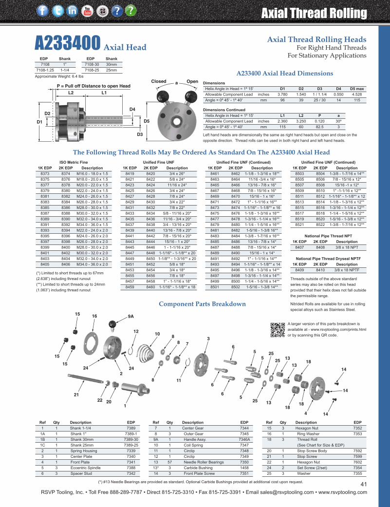
RSVP Tooling, Inc. • Toll Free 888-289-7787 • Direct 815-725-3310 • Fax 815-725-3391 • Email [email protected] • www.rsvptooling.com
Axial Thread Rolling
A233400 Axial HeadAxial Thread Rolling Heads
For Right Hand ThreadsFor Stationary Applications
118
24 242
6
6
521
22 201
15
15
18
4
1818
1325
14
13
13
56
3
525
25
78
810
12
16159A
14
14
Dimensions
Helix Angle in Head = 1º 15' D1 D2 D3 D4 D5 max
Allowable Component Lead inches 3.780 1.540 1 / 1.1/4 0.550 4.528
Angle = 0º 45' - 1º 40' mm 96 39 25 / 30 14 115
Dimensions Continued
Helix Angle in Head = 1º 15' L1 L2 P a
Allowable Component Lead inches 2.360 3.250 0.120 30º
Angle = 0º 45' - 1º 40' mm 115 60 82.5 3
Ref Qty Description EDP
15 3 Hexagon Nut 7352
16 1 Ring Washer 7353
18 3 Thread Roll
(See Chart for Size & EDP)
20 1 Stop Screw Body 7592
21 1 Stop Screw 7599
22 1 Hexagon Nut 7602
24 2 Set Screw (2/set) 7354
25 3 Washer 7355
Ref Qty Description EDP
1 1 Shank 1-1/4 7389
1A 1 Shank 1" 7389-1
1B 1 Shank 30mm 7389-30
1C 1 Shank 25mm 7389-25
2 1 Spring Housing 7339
3 1 Center Plate 7340
4 1 Front Plate 7341
5 3 Eccentric Spindle 7388
6 3 Spacer Stud 7342
Ref Qty Description EDP
7 1 Center Gear 7344
8 3 Outer Gear 7345
9A 1 Handle Assy. 7346A
10 1 Coil Spring 7347
11 1 Circlip 7348
12 1 Circlip 7349
13 57 Needle Roller Bearings 7350
13* 3 Carbide Bushing 1458
14 3 Front Plate Screw 7351
(*) #13 Needle Bearings are provided as standard. Optional Carbide Bushings provided at additional cost upon request.
The Following Thread Rolls May Be Ordered As Standard On The A233400 Axial Head
A233400 Axial Head Dimensions
ISO Metric Fine
1K EDP 2K EDP Description
8373 8374 M16.0 - 18.0 x 1.5
8375 8376 M18.0 - 20.0 x 1.5
8377 8378 M20.0 - 22.0 x 1.5
8379 8380 M22.0 - 24.0 x 1.5
8381 8382 M24.0 - 26.0 x 1.5
8383 8384 M26.0 - 28.0 x 1.5
8385 8386 M28.0 - 30.0 x 1.5
8387 8388 M30.0 - 32.0 x 1.5
8389 8390 M32.0 - 34.0 x 1.5
8391 8392 M34.0 - 36.0 x 1.5
8393 8394 M22.0 - 24.0 x 2.0
8395 8396 M24.0 - 26.0 x 2.0
8397 8398 M26.0 - 28.0 x 2.0
8399 8400 M28.0 - 30.0 x 2.0
8401 8402 M30.0 - 32.0 x 2.0
8403 8404 M32.0 - 34.0 x 2.0
8405 8406 M34.0 - 36.0 x 2.0
Unified Fine UNF (Continued)
1K EDP 2K EDP Description
8461 8462 1-1/8 - 1-3/16 x 18**
8463 8464 11/16 -3/4 x 16*
8465 8466 13/16 - 7/8 x 16*
8467 8468 7/8 - 15/16 x 16*
8469 8470 15/16 - 1 x 16*
8471 8472 1" - 1-1/16 x 16*"
8473 8474 1-1/16* - 1-1/8** x 16
8475 8476 1-1/8 - 1-3/16 x 16**
8477 8478 1-3/16 - 1-1/4 x 16**
8479 8480 1-1/4 - 1-5/16 x 16**
8481 8482 1-5/16 - 1-3/8 16**
8483 8484 1-3/8 - 1-7/16 x 16**
8485 8486 13/16 - 7/8 x 14*
8487 8488 7/8 - 15/16 x 14*
8489 8490 15/16 - 1 x 14*
8491 8492 1" - 1-1/16 x 14*"
8493 8494 1-1/16* - 1-1/8** x 14
8495 8496 1-1/8 - 1-3/16 x 14**
8497 8498 1-3/16 - 1-1/4 x 14**
8499 8500 1-1/4 - 1-5/16 x 14**
8501 8502 1-5/16 - 1-3/8 14**
Unified Fine UNF (Continued)
1K EDP 2K EDP Description
8503 8504 1-3/8 - 1-7/16 x 14**
8505 8506 7/8 - 15/16 x 12*
8507 8508 15/16 -1 x 12*
8509 8510 1" -1-1/16 x 12*"
8511 8512 1-1/16* - 1-1/8** x 12
8513 8514 1-1/8 - 1-3/16 x 12**
8515 8516 1-3/16 - 1-1/4 x 12**
8517 8518 1-1/4 - 1-5/16 x 12**
8519 8520 1-5/16 - 1-3/8 x 12**
8521 8522 1-3/8 - 1-7/16 x 12**
National Pipe Thread NPT
1K EDP 2K EDP Description
8407 8408 3/8 x 18 NPT
National Pipe Thread Dryseal NPTF
1K EDP 2K EDP Description
8409 8410 3/8 x 18 NPTF
Unified Fine UNF
1K EDP 2K EDP Description
8419 8420 3/4 x 26*
8421 8422 5/8 x 24*
8423 8424 11/16 x 24*
8425 8426 3/4 x 24*
8427 8428 7/8 x 24*
8429 8430 3/4 x 22*
8431 8432 7/8 x 22*
8433 8434 5/8 - 11/16 x 20*
8435 8436 11/16 - 3/4 x 20*
8437 8438 3/4 - 13/16 x 20*
8439 8440 13/16 - 7/8 x 20*
8441 8442 7/8 - 15/16 x 20*
8443 8444 15/16 - 1 x 20*
8445 8446 1 - 1-1/16 x 20*
8447 8448 1-1/16* - 1-1/8** x 20
8449 8450 1-1/8** - 1-3/16** x 20
8451 8452 5/8 x 18*
8453 8454 3/4 x 18*
8455 8456 7/8 x 18*
8457 8458 1” - 1-1/16 x 18*
8459 8460 1-1/16* - 1-1/8** x 18
Left hand heads are dimensionally the same as right hand heads but open and close on the
opposite direction. Thread rolls can be used in both right hand and left hand heads.
(*) Limited to short threads up to 67mm
(2.638”) including thread runout
(**) Limited to short threads up to 24mm
(1.063”) including thread runout
Component Parts Breakdown
Threads outside of the above standard
series may also be rolled on this head
provided that their helix does not fall outside
the permissible range.
Nitrided Rolls are available for use in rolling
special alloys such as Stainless Steel.
L1L2
P = Pull off Distance to open Head
D2D4
D3
D5
aClosed Open
D1
EDP Shank
7108 1”
7108-1.25 1-1/4
EDP Shank
7108-30 30mm
7108-25 25mm
A larger version of this parts breakdown is
available at - www.rsvptooling.com/prints.html
or by scanning this QR code.
41
Approximate Weight: 6.4 lbs
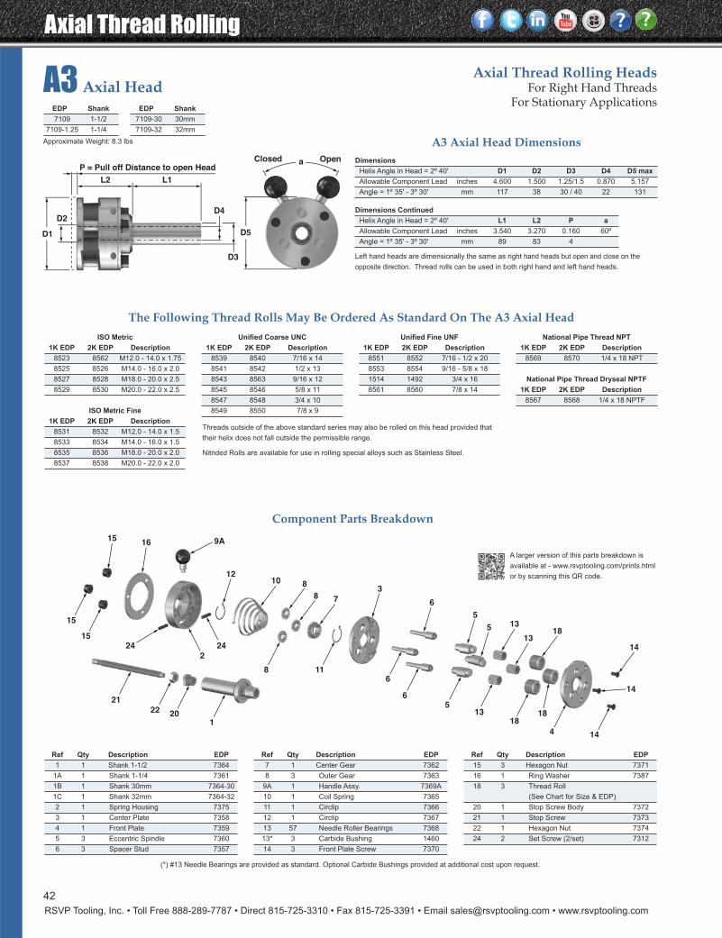
Axial Thread Rolling
RSVP Tooling, Inc. • Toll Free 888-289-7787 • Direct 815-725-3310 • Fax 815-725-3391 • Email [email protected] • www.rsvptooling.com
A3 Axial HeadAxial Thread Rolling Heads
For Right Hand ThreadsFor Stationary Applications
6
118
24 24
2
6
521
22 201
15
15
18
4
1818
13
14
13
135
6
3
5
78
81012
1615 9A
14
14
42
Dimensions
Helix Angle in Head = 2º 40' D1 D2 D3 D4 D5 max
Allowable Component Lead inches 4.600 1.500 1.25/1.5 0.870 5.157
Angle = 1º 35' - 3º 30' mm 117 38 30 / 40 22 131
Dimensions Continued
Helix Angle in Head = 2º 40' L1 L2 P a
Allowable Component Lead inches 3.540 3.270 0.160 60º
Angle = 1º 35' - 3º 30' mm 89 83 4
Component Parts Breakdown
Ref Qty Description EDP
15 3 Hexagon Nut 7371
16 1 Ring Washer 7387
18 3 Thread Roll
(See Chart for Size & EDP)
20 1 Stop Screw Body 7372
21 1 Stop Screw 7373
22 1 Hexagon Nut 7374
24 2 Set Screw (2/set) 7312
Ref Qty Description EDP
1 1 Shank 1-1/2 7364
1A 1 Shank 1-1/4 7361
1B 1 Shank 30mm 7364-30
1C 1 Shank 32mm 7364-32
2 1 Spring Housing 7375
3 1 Center Plate 7358
4 1 Front Plate 7359
5 3 Eccentric Spindle 7360
6 3 Spacer Stud 7357
Ref Qty Description EDP
7 1 Center Gear 7362
8 3 Outer Gear 7363
9A 1 Handle Assy. 7369A
10 1 Coil Spring 7365
11 1 Circlip 7366
12 1 Circlip 7367
13 57 Needle Roller Bearings 7368
13* 3 Carbide Bushing 1460
14 3 Front Plate Screw 7370
(*) #13 Needle Bearings are provided as standard. Optional Carbide Bushings provided at additional cost upon request.
The Following Thread Rolls May Be Ordered As Standard On The A3 Axial Head
A3 Axial Head Dimensions
ISO Metric
1K EDP 2K EDP Description
8523 8562 M12.0 - 14.0 x 1.75
8525 8526 M14.0 - 16.0 x 2.0
8527 8528 M18.0 - 20.0 x 2.5
8529 8530 M20.0 - 22.0 x 2.5
ISO Metric Fine
1K EDP 2K EDP Description
8531 8532 M12.0 - 14.0 x 1.5
8533 8534 M14.0 - 16.0 x 1.5
8535 8536 M18.0 - 20.0 x 2.0
8537 8538 M20.0 - 22.0 x 2.0
Unified Fine UNF
1K EDP 2K EDP Description
8551 8552 7/16 - 1/2 x 20
8553 8554 9/16 - 5/8 x 18
1514 1492 3/4 x 16
8561 8560 7/8 x 14
National Pipe Thread NPT
1K EDP 2K EDP Description
8569 8570 1/4 x 18 NPT
National Pipe Thread Dryseal NPTF
1K EDP 2K EDP Description
8567 8568 1/4 x 18 NPTF
Unified Coarse UNC
1K EDP 2K EDP Description
8539 8540 7/16 x 14
8541 8542 1/2 x 13
8543 8563 9/16 x 12
8545 8546 5/8 x 11
8547 8548 3/4 x 10
8549 8550 7/8 x 9
Left hand heads are dimensionally the same as right hand heads but open and close on the
opposite direction. Thread rolls can be used in both right hand and left hand heads.
Threads outside of the above standard series may also be rolled on this head provided that
their helix does not fall outside the permissible range.
Nitrided Rolls are available for use in rolling special alloys such as Stainless Steel.
L1L2
P = Pull off Distance to open Head
D2D4
D3
D5
aClosed Open
D1
EDP Shank
7109 1-1/2
7109-1.25 1-1/4
EDP Shank
7109-30 30mm
7109-32 32mm
A larger version of this parts breakdown is
available at - www.rsvptooling.com/prints.html
or by scanning this QR code.
Approximate Weight: 8.3 lbs
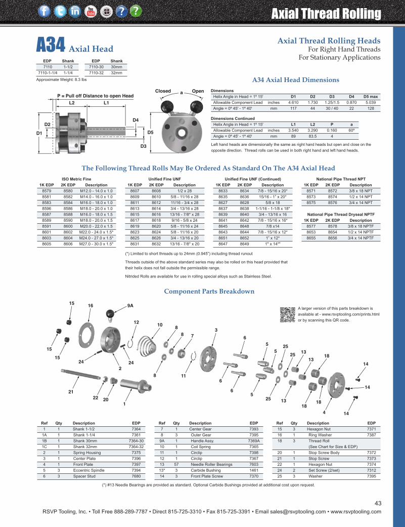
RSVP Tooling, Inc. • Toll Free 888-289-7787 • Direct 815-725-3310 • Fax 815-725-3391 • Email [email protected] • www.rsvptooling.com
Axial Thread Rolling
43
A34 Axial HeadAxial Thread Rolling Heads
For Right Hand ThreadsFor Stationary Applications
118
24 24
2
6
6
521
22 201
15
15
18
4
1818
1325
14
13
13
5
6
3
525
25
78
810
12
1615
9A
14
14
Dimensions
Helix Angle in Head = 1º 15' D1 D2 D3 D4 D5 max
Allowable Component Lead inches 4.610 1.730 1.25/1.5 0.870 5.039
Angle = 0º 45' - 1º 40' mm 117 44 30 / 40 22 128
Dimensions Continued
Helix Angle in Head = 1º 15' L1 L2 P a
Allowable Component Lead inches 3.540 3.290 0.160 60º
Angle = 0º 45' - 1º 40' mm 89 83.5 4
Component Parts Breakdown
The Following Thread Rolls May Be Ordered As Standard On The A34 Axial Head
A34 Axial Head Dimensions
Left hand heads are dimensionally the same as right hand heads but open and close on the
opposite direction. Thread rolls can be used in both right hand and left hand heads.
ISO Metric Fine
1K EDP 2K EDP Description
8579 8580 M12.0 - 14.0 x 1.0
8581 8582 M14.0 - 16.0 x 1.0
8583 8584 M16.0 - 18.0 x 1.0
8596 8586 M18.0 - 20.0 x 1.0
8587 8588 M16.0 - 18.0 x 1.5
8589 8590 M18.0 - 20.0 x 1.5
8591 8600 M20.0 - 22.0 x 1.5
8601 8602 M22.0 - 24.0 x 1.5*
8603 8604 M24.0 - 27.0 x 1.5*
8605 8606 M27.0 - 30.0 x 1.5*
Unified Fine UNF (Continued)
1K EDP 2K EDP Description
8633 8634 7/8 - 15/16 x 20*
8635 8636 15/16 - 1” x 20*
8627 8628 5/8 x 18
8637 8638 1-1/16 - 1-1/8 x 18*
8639 8640 3/4 - 13/16 x 16
8641 8642 7/8 - 15/16 x 16*
8645 8648 7/8 x14
8643 8644 7/8 - 15/16 x 12*
8651 8652 1” x 12*
8647 8649 1" x 14*"
National Pipe Thread NPT
1K EDP 2K EDP Description
8571 8572 3/8 x 18 NPT
8573 8574 1/2 x 14 NPT
8575 8576 3/4 x 14 NPT
National Pipe Thread Dryseal NPTF
1K EDP 2K EDP Description
8577 8578 3/8 x 18 NPTF
8653 8654 1/2 x 14 NPTF
8655 8656 3/4 x 14 NPTF
Unified Fine UNF
1K EDP 2K EDP Description
8607 8608 1/2 x 28
8609 8610 5/8 - 11/16 x 28
8611 8612 11/16 - 3/4 x 28
8613 8614 3/4 - 13/16 x 28
8615 8616 13/16 - 7/8* x 28
8617 8618 9/16 - 5/8 x 24
8619 8620 5/8 - 11/16 x 24
8623 8624 5/8 - 11/16 x 20
8625 8626 3/4 - 13/16 x 20
8631 8632 13/16 - 7/8* x 20
Ref Qty Description EDP
15 3 Hexagon Nut 7371
16 1 Ring Washer 7387
18 3 Thread Roll
(See Chart for Size & EDP)
20 1 Stop Screw Body 7372
21 1 Stop Screw 7373
22 1 Hexagon Nut 7374
24 2 Set Screw (2/set) 7312
25 3 Washer 7395
Ref Qty Description EDP
1 1 Shank 1-1/2 7364
1A 1 Shank 1-1/4 7361
1B 1 Shank 30mm 7364-30
1C 1 Shank 32mm 7364-32
2 1 Spring Housing 7375
3 1 Center Plate 7396
4 1 Front Plate 7397
5 3 Eccentric Spindle 7394
6 3 Spacer Stud 7680
Ref Qty Description EDP
7 1 Center Gear 7393
8 3 Outer Gear 7395
9A 1 Handle Assy. 7369A
10 1 Coil Spring 7365
11 1 Circlip 7398
12 1 Circlip 7367
13 57 Needle Roller Bearings 7603
13* 3 Carbide Bushing 1461
14 3 Front Plate Screw 7370
(*) #13 Needle Bearings are provided as standard. Optional Carbide Bushings provided at additional cost upon request.
(*) Limited to short threads up to 24mm (0.945”) including thread runout
Threads outside of the above standard series may also be rolled on this head provided that
their helix does not fall outside the permissible range.
Nitrided Rolls are available for use in rolling special alloys such as Stainless Steel.
L1L2
P = Pull off Distance to open Head
D2D4
D3
D5
aClosed Open
D1
EDP Shank
7110 1-1/2
7110-1-1/4 1-1/4
EDP Shank
7110-30 30mm
7110-32 32mm
A larger version of this parts breakdown is
available at - www.rsvptooling.com/prints.html
or by scanning this QR code.
Approximate Weight: 8.3 lbs
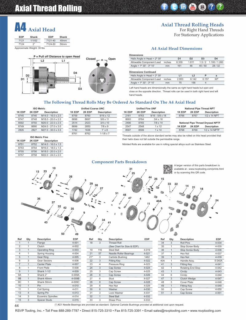
Ref Qty Description EDP
34 3 Roll Pins 4-034
35 1 Stop Screw Body 4-035
36 1 Stop Screw Body 4-036
37 1 Hex Nut 4-037
39 1 Hex Nut 4-039
40A 1 Handle Assy. 4-040A
41 3 Fitting Key 4-041
42 1 Rotating End Stop 4-042
43 1 Circlip 4-043
44 6 Circlip 4-044
47 3 Clutch Wedge 4-047
48 3 Cover Plate 4-048
49 1 Fitting Key 4-049
50 2 Cap Screw 4-050
51 3 Cap Screw 4-051
Ref Qty Description EDP
1 1 Flange 4-001
2 1 Clutch 4-002
3 1 Operating Ring 4-003
4 1 Spring Housing 4-004
5 1 Gear Ring 4-005
6 3 Gear Sectors 4-006
7 1 Center Plate 4-007
8 1 Front Plate 4-008
9 1 Shank 1-1/2 4-009
9A 1 Shank 2” 4-009A
9B 1 Shank 40mm 4-009B
9C 1 Shank 50mm 4-009C
10 1 Pin 4-010
11 1 Coil Spring 4-011
13 4 Spring Pin 4-013
14 3 Eccentric Spindles 4-014
15 3 Spacer Studs 4-015
Ref Qty Description EDP
18 3 Thread Roll
(See Chart for Size & EDP)
19 116 Steel Ball 4-019
21 57 Needle Roller Bearings 4-021
21* 3 Carbide Bushing 1462
22 3 Fitting Key 4-022
23 4 Pressure Ring 4-023
24 3 Cap Screw 4-024
25 3 Cap Screw 4-025
26 6 Cap Screw 4-026
27 6 Stud 4-027
28 8 Cap Screw 4-028
29 6 Hex Nut 4-029
30 6 Washer 4-030
31 3 Lock Washer 4-031
32 1 Steel Ball 4-032
33 3 Shear Pins 4-033
(*) #21 Needle Bearings are provided as standard. Optional Carbide Bushings provided at additional cost upon request.
Axial Thread Rolling
RSVP Tooling, Inc. • Toll Free 888-289-7787 • Direct 815-725-3310 • Fax 815-725-3391 • Email [email protected] • www.rsvptooling.com
44
A4 Axial HeadAxial Thread Rolling Heads
For Right Hand ThreadsFor Stationary Applications
8
24
1821
1422
1526
7
44
25
31
6
19
5
40A
33
11
44748
51
4134
1
9
354232
37
36
2730
29
3
282
102313
43
50 49
EDP Shank
7121 1/1/02
7124 2”
EDP Shank
7121-40 40mm
7124-50 50mm
Dimensions
Helix Angle in Head = 2º 30' D1 D2 D3 D4
Allowable Component Lead inches 6.339 1.811 1.5 / 2 1.100 / 1.260
Angle = 1º 30' - 3º 10' mm 161 46 40 / 50 28 / 32
Dimensions Continued
Helix Angle in Head = 2º 30' L1 L2 P a
Allowable Component Lead inches 2.953 6.142 0.157 30º
Angle = 1º 30' - 3º 10' mm 75 156 4
A4 Axial Head Dimensions
Left hand heads are dimensionally the same as right hand heads but open and
close on the opposite direction. Thread rolls can be used in both right hand and left
hand heads.
The Following Thread Rolls May Be Ordered As Standard On The A4 Axial HeadISO Metric
1K EDP 2K EDP Description
8745 8746 M14.0 - 16.0 x 2.0
8747 8748 M18.0 - 20.0 x 2.5
8592 8750 M20.0 - 22.0 x 2.5
8749 8690 M24.0 - 27.0 x 3.0
2826 2827 M27.0 - 30.0 x 3.5
ISO Metric Fine
1K EDP 2K EDP Description
8751 8752 M14.0 - 16.0 x 1.5
8753 8754 M16.0 - 18.0 x 1.5
8755 8756 M18.0 - 20.0 x 2.0
8757 8758 M22.0 - 24.0 x 2.0
Unified Fine UNF
1K EDP 2K EDP Description
2181 8763 9/16 - 5/8 x 18
8693 8764 3/4 x 16
2496 8765 7/8 x 14
2547 2548 1 x 12
8597 8599 1 x 14
National Pipe Thread NPT
1K EDP 2K EDP Description
8766 8767 1/2 x 14 NPT
National Pipe Thread Dryseal NPTF
1K EDP 2K EDP Description
8768 8769 1/2 x 14 NPTF
Unified Coarse UNC
1K EDP 2K EDP Description
8759 8760 9/16 x 12
8696 8697 5/8 x 11
2514 2523 3/4 x 10
8699 2850 7/8 x 9
1742 1638 1” x 8
8761 8762 1-1/8 x 7
Component Parts Breakdown
Threads outside of the above standard series may also be rolled on this head provided that
their helix does not fall outside the permissible range.
Nitrided Rolls are available for use in rolling special alloys such as Stainless Steel.
L1L2
P = Pull off Distance to open Head
D2D4
D3
aClosed Open
D1
A larger version of this parts breakdown is
available at - www.rsvptooling.com/prints.html
or by scanning this QR code.
Approximate Weight: 30 lbs
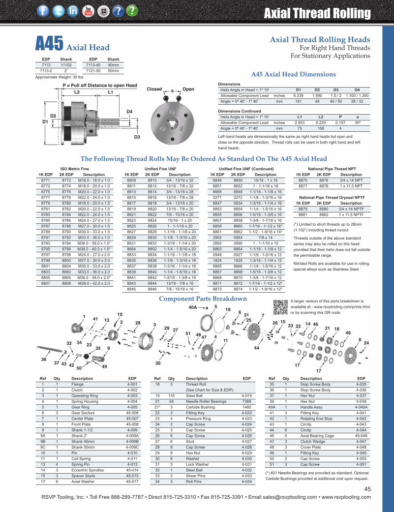
RSVP Tooling, Inc. • Toll Free 888-289-7787 • Direct 815-725-3310 • Fax 815-725-3391 • Email [email protected] • www.rsvptooling.com
Axial Thread Rolling
45
A45 Axial HeadAxial Thread Rolling Heads
For Right Hand ThreadsFor Stationary Applications
824
17
17
1846
4621
1422
1526
7
44
2531
619
540A
33
11447
4851
41
34
1
935
42
32
3736
27
30
293282
10
23
13
4350 49
Ref Qty Description EDP
35 1 Stop Screw Body 4-035
36 1 Stop Screw Body 4-036
37 1 Hex Nut 4-037
39 1 Hex Nut 4-039
40A 1 Handle Assy. 4-040A
41 3 Fitting Key 4-041
42 1 Rotating End Stop 4-042
43 1 Circlip 4-043
44 6 Circlip 4-044
46 6 Axial Bearing Cage 45-046
47 3 Clutch Wedge 4-047
48 3 Cover Plate 4-048
49 1 Fitting Key 4-049
50 2 Cap Screw 4-050
51 3 Cap Screw 4-051
Ref Qty Description EDP
1 1 Flange 4-001
2 1 Clutch 4-002
3 1 Operating Ring 4-003
4 1 Spring Housing 4-004
5 1 Gear Ring 4-005
6 3 Gear Sectors 45-006
7 1 Center Plate 45-007
8 1 Front Plate 45-008
9 1 Shank 1-1/2 4-009
9A 1 Shank 2” 4-009A
9B 1 Shank 40mm 4-009B
9C 1 Shank 50mm 4-009C
10 1 Pin 4-010
11 1 Coil Spring 4-011
13 4 Spring Pin 4-013
14 3 Eccentric Spindles 45-014
15 3 Spacer Studs 45-015
17 6 Axial Washer 45-017
Ref Qty Description EDP
18 3 Thread Roll
(See Chart for Size & EDP)
19 116 Steel Ball 4-019
21 54 Needle Roller Bearings 7368
21* 3 Carbide Bushing 1460
22 3 Fitting Key 4-022
23 4 Pressure Ring 4-023
24 3 Cap Screw 4-024
25 3 Cap Screw 4-025
26 6 Cap Screw 4-026
27 6 Stud 4-027
28 8 Cap Screw 4-028
29 6 Hex Nut 4-029
30 6 Washer 4-030
31 3 Lock Washer 4-031
32 1 Steel Ball 4-032
33 3 Shear Pins 4-033
34 3 Roll Pins 4-034
(*) #21 Needle Bearings are provided as standard. Optional
Carbide Bushings provided at additional cost upon request.
The Following Thread Rolls May Be Ordered As Standard On The A45 Axial HeadISO Metric Fine
1K EDP 2K EDP Description
8771 8772 M16.0 - 18.0 x 1.0
8773 8774 M18.0 - 20.0 x 1.0
8775 8776 M20.0 - 22.0 x 1.0
8777 8778 M22.0 - 24.0 x 1.0
8779 8780 M18.0 - 20.0 x 1.5
8781 8782 M20.0 - 22.0 x 1.5
8783 8784 M22.0 - 24.0 x 1.5
8785 8786 M24.0 - 27.0 x 1.5
8787 8788 M27.0 - 30.0 x 1.5
8789 8790 M30.0 - 33.0 x 1.5
8791 8792 M33.0 - 36.0 x 1.5
8793 8794 M36.0 - 39.0 x 1.5*
8795 8796 M38.0 - 40.0 x 1.5*
8797 8798 M24.0 - 27.0 x 2.0
8799 8800 M27.0 - 30.0 x 2.0
8801 8804 M30.0 - 33.0 x 2.0
8803 8660 M33.0 - 36.0 x 2.0
8805 8806 M36.0 - 39.0 x 2.0*
8807 8808 M39.0 - 42.0 x 2.0
Unified Fine UNF (Continued)
1K EDP 2K EDP Description
8849 8850 15/16 - 1 x 16
8851 8852 1 - 1-1/16 x 16
8665 8848 1-1/16 - 1-1/8 x 16
2271 2272 1-1/8 - 1-3/16 x 16
8847 0934 1-3/16 - 1-1/4 x 16
8853 8854 1-1/4 - 1-5/16 x 16
8855 8856 1-5/16 - 1-3/8 x 16
8857 8858 1-3/8 - 1-7/16 x 16
8859 8860 1-7/16 - 1-1/2 x 16*
8861 8862 1-1/2 - 1-9/16 x 16*
2902 0954 7/8 x 14
2892 2890 1 - 1-1/16 x 12
8863 8864 1-1/16 - 1-1/8 x 12
0948 0927 1-1/8 - 1-3/16 x 12
1824 1825 1-3/16 - 1-1/4 x 12
8865 8866 1-1/4 - 1-5/16 x 12
8867 8868 1-5/16 - 1-3/8 x 12
8869 8870 1-3/8 - 1-7/16 x 12
8871 8872 1-7/16 - 1-1/2 x 12*
8873 8874 1-1/2 - 1-9/16 x 12*
National Pipe Thread NPT
1K EDP 2K EDP Description
8875 8876 3/4 x 14 NPT
8877 8878 1 x 11.5 NPT
National Pipe Thread Dryseal NPTF
1K EDP 2K EDP Description
8879 8880 3/4 x 14 NPTF
8881 8882 1 x 11.5 NPTF
Unified Fine UNF
1K EDP 2K EDP Description
8809 8810 3/4 - 13/16 x 32
8811 8812 13/16 - 7/8 x 32
8813 8814 3/4 - 13/16 x 28
8815 8816 13/16 - 7/8 x 28
8817 8818 3/4 - 13/16 x 20
8819 8820 13/16 - 7/8 x 20
8821 8822 7/8 - 15/16 x 20
8823 8824 15/16 - 1 x 20
8825 8826 1 - 1-1/16 x 20
8827 8828 1-1/16 - 1-1/8 x 20
8829 8830 1-1/8 - 1-3/16 x 20
8831 8832 1-3/16 - 1-1/4 x 20
8664 8802 1-1/4 - 1-5/16 x 20
8833 8834 1-1/16 - 1-1/8 x 18
8835 8836 1-1/8 - 1-3/16 x 18
8837 8838 1-3/16 - 1-1/4 x 18
8839 8840 1-1/4 - 1-5/16 x 18
8841 8842 1-5/16 - 1-3/8 x 18
8843 8844 13/16 - 7/8 x 16
8845 8846 7/8 - 15/16 x 16
EDP Shank
7113 1/1/02
7113-2 2”
EDP Shank
7113-40 40mm
7121-50 50mm
Component Parts Breakdown
(*) Limited to short threads up to 28mm
(1.102”) including thread runout
Threads outside of the above standard
series may also be rolled on this head
provided that their helix does not fall outside
the permissible range.
Nitrided Rolls are available for use in rolling
special alloys such as Stainless Steel.
Dimensions
Helix Angle in Head = 1º 10' D1 D2 D3 D4
Allowable Component Lead inches 6.339 1.890 1.5 / 2 1.100 / 1.260
Angle = 0º 40' - 1º 40' mm 161 48 40 / 50 28 / 32
Dimensions Continued
Helix Angle in Head = 1º 10' L1 L2 P a
Allowable Component Lead inches 2.953 6.220 0.157 30º
Angle = 0º 40' - 1º 40' mm 75 158 4
A45 Axial Head Dimensions
Left hand heads are dimensionally the same as right hand heads but open and
close on the opposite direction. Thread rolls can be used in both right hand and left
hand heads.
L1L2
P = Pull off Distance to open Head
D2D4
D3
aClosed Open
D1
A larger version of this parts breakdown is
available at - www.rsvptooling.com/prints.html
or by scanning this QR code.
Approximate Weight: 30 lbs
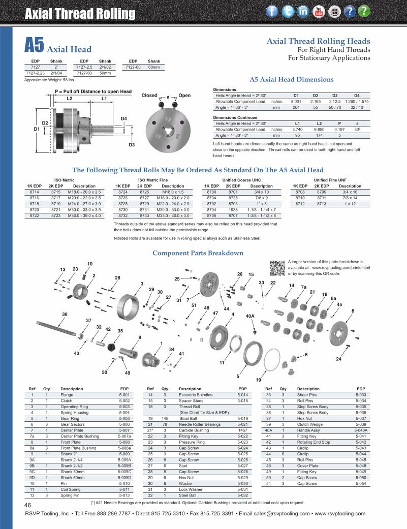
Axial Thread Rolling
RSVP Tooling, Inc. • Toll Free 888-289-7787 • Direct 815-725-3310 • Fax 815-725-3391 • Email [email protected] • www.rsvptooling.com
A5 Axial HeadAxial Thread Rolling Heads
For Right Hand ThreadsFor Stationary Applications
8
24
18
7a
8a
45
21
1422
1526
7
44
25
31
6
195
40A
33
11
44748
51
4134
1
9
354232
37
36
2730
29
3
282
102313
43
50 49
Ref Qty Description EDP
33 3 Shear Pins 5-033
34 3 Roll Pins 5-034
35 1 Stop Screw Body 5-035
36 1 Stop Screw Body 5-036
37 1 Hex Nut 5-037
39 3 Clutch Wedge 5-039
40A 1 Handle Assy. 5-040A
41 3 Fitting Key 5-041
42 1 Rotating End Stop 5-042
43 1 Circlip 5-043
44 6 Circlip 5-044
45 3 Roll Pins 5-045
48 3 Cover Plate 5-048
49 1 Fitting Key 5-049
50 2 Cap Screw 5-050
54 3 Cap Screw 5-054
Ref Qty Description EDP
1 1 Flange 5-001
2 1 Clutch 5-002
3 1 Operating Ring 5-003
4 1 Spring Housing 5-004
5 1 Gear Ring 5-005
6 3 Gear Sectors 5-006
7 1 Center Plate 5-007
7a 3 Center Plate Bushing 5-007a
8 1 Front Plate 5-008
8a 3 Front Plate Bushing 5-008a
9 1 Shank 2" 5-009
9A Shank 2-1/4 5-009A
9B 1 Shank 2-1/2 5-009B
9C 1 Shank 50mm 5-009C
9D 1 Shank 60mm 5-009D
10 1 Pin 5-010
11 1 Coil Spring 5-011
13 3 Spring Pin 5-013
Ref Qty Description EDP
14 3 Eccentric Spindles 5-014
15 3 Spacer Studs 5-015
18 3 Thread Roll
(See Chart for Size & EDP)
19 145 Steel Ball 5-019
21 78 Needle Roller Bearings 5-021
21* 3 Carbide Bushing 1457
22 3 Fitting Key 5-022
23 3 Pressure Ring 5-023
24 3 Cap Screw 5-024
25 3 Cap Screw 5-025
26 6 Cap Screw 5-026
27 6 Stud 5-027
28 8 Cap Screw 5-028
29 6 Hex Nut 5-029
30 6 Washer 5-030
31 3 Lock Washer 5-031
32 1 Steel Ball 5-032
Component Parts Breakdown
EDP Shank
7127 2”
7127-2.25 2/1/04
EDP Shank
7127-2.5 2/1/02
7127-50 50mm
Dimensions
Helix Angle in Head = 2º 30' D1 D2 D3 D4
Allowable Component Lead inches 8.031 2.165 2 / 2.5 1.260 / 1.575
Angle = 1º 30' - 3º mm 204 55 50 / 70 32 / 40
Dimensions Continued
Helix Angle in Head = 2º 30' L1 L2 P a
Allowable Component Lead inches 3.740 6.850 0.197 30º
Angle = 1º 30' - 3º mm 95 174 5
A5 Axial Head Dimensions
Left hand heads are dimensionally the same as right hand heads but open and
close on the opposite direction. Thread rolls can be used in both right hand and left
hand heads.
The Following Thread Rolls May Be Ordered As Standard On The A5 Axial HeadISO Metric
1K EDP 2K EDP Description
8714 8715 M18.0 - 20.0 x 2.5
8716 8717 M20.0 - 22.0 x 2.5
8718 8719 M24.0 - 27.0 x 3.0
8720 8721 M30.0 - 33.0 x 3.5
8722 8723 M36.0 - 39.0 x 4.0
Unified Coarse UNC
1K EDP 2K EDP Description
8700 8701 3/4 x 10
8734 8735 7/8 x 9
8702 8703 1” x 8
8704 1938 1-1/8 - 1-1/4 x 7
8706 8707 1-3/8 - 1-1/2 x 6
Unified Fine UNF
1K EDP 2K EDP Description
8708 8709 3/4 x 16
8710 8711 7/8 x 14
8712 8713 1 x 12
ISO Metric Fine
1K EDP 2K EDP Description
8724 8725 M18.0 x 1.5
8726 8727 M18.0 - 20.0 x 2.0
8728 8729 M22.0 - 24.0 x 2.0
8730 8731 M30.0 - 33.0 x 3.0
8732 8733 M33.0 - 36.0 x 3.0
Threads outside of the above standard series may also be rolled on this head provided that
their helix does not fall outside the permissible range.
Nitrided Rolls are available for use in rolling special alloys such as Stainless Steel.
EDP Shank
7127-60 60mm
L1L2
P = Pull off Distance to open Head
D2D4
D3
aClosed Open
D1
A larger version of this parts breakdown is
available at - www.rsvptooling.com/prints.html
or by scanning this QR code.
(*) #21 Needle Bearings are provided as standard. Optional Carbide Bushings provided at additional cost upon request.46
Approximate Weight: 58 lbs
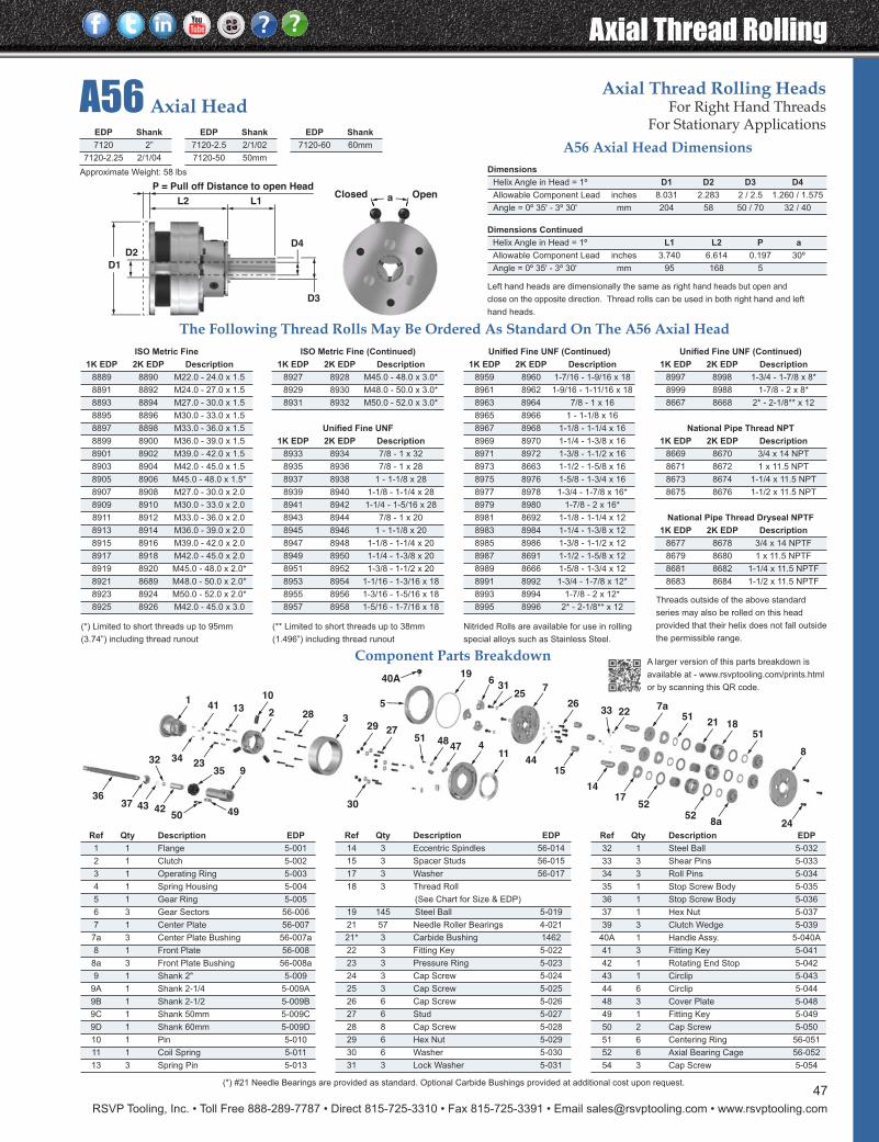
RSVP Tooling, Inc. • Toll Free 888-289-7787 • Direct 815-725-3310 • Fax 815-725-3391 • Email [email protected] • www.rsvptooling.com
Axial Thread Rolling
A56 Axial HeadAxial Thread Rolling Heads
For Right Hand ThreadsFor Stationary Applications
8
248a52
1851
21
14
22
15
26
7
44
2531
6
7a
5217
51
19
5
40A
33
11447
4851
41
34
1
935
42
32
3736
27
30
293282
10
23
13
4350 49
Ref Qty Description EDP
32 1 Steel Ball 5-032
33 3 Shear Pins 5-033
34 3 Roll Pins 5-034
35 1 Stop Screw Body 5-035
36 1 Stop Screw Body 5-036
37 1 Hex Nut 5-037
39 3 Clutch Wedge 5-039
40A 1 Handle Assy. 5-040A
41 3 Fitting Key 5-041
42 1 Rotating End Stop 5-042
43 1 Circlip 5-043
44 6 Circlip 5-044
48 3 Cover Plate 5-048
49 1 Fitting Key 5-049
50 2 Cap Screw 5-050
51 6 Centering Ring 56-051
52 6 Axial Bearing Cage 56-052
54 3 Cap Screw 5-054
Ref Qty Description EDP
1 1 Flange 5-001
2 1 Clutch 5-002
3 1 Operating Ring 5-003
4 1 Spring Housing 5-004
5 1 Gear Ring 5-005
6 3 Gear Sectors 56-006
7 1 Center Plate 56-007
7a 3 Center Plate Bushing 56-007a
8 1 Front Plate 56-008
8a 3 Front Plate Bushing 56-008a
9 1 Shank 2" 5-009
9A 1 Shank 2-1/4 5-009A
9B 1 Shank 2-1/2 5-009B
9C 1 Shank 50mm 5-009C
9D 1 Shank 60mm 5-009D
10 1 Pin 5-010
11 1 Coil Spring 5-011
13 3 Spring Pin 5-013
Ref Qty Description EDP
14 3 Eccentric Spindles 56-014
15 3 Spacer Studs 56-015
17 3 Washer 56-017
18 3 Thread Roll
(See Chart for Size & EDP)
19 145 Steel Ball 5-019
21 57 Needle Roller Bearings 4-021
21* 3 Carbide Bushing 1462
22 3 Fitting Key 5-022
23 3 Pressure Ring 5-023
24 3 Cap Screw 5-024
25 3 Cap Screw 5-025
26 6 Cap Screw 5-026
27 6 Stud 5-027
28 8 Cap Screw 5-028
29 6 Hex Nut 5-029
30 6 Washer 5-030
31 3 Lock Washer 5-031
(*) #21 Needle Bearings are provided as standard. Optional Carbide Bushings provided at additional cost upon request.
Component Parts Breakdown
Dimensions
Helix Angle in Head = 1º D1 D2 D3 D4
Allowable Component Lead inches 8.031 2.283 2 / 2.5 1.260 / 1.575
Angle = 0º 35' - 3º 30' mm 204 58 50 / 70 32 / 40
Dimensions Continued
Helix Angle in Head = 1º L1 L2 P a
Allowable Component Lead inches 3.740 6.614 0.197 30º
Angle = 0º 35' - 3º 30' mm 95 168 5
A56 Axial Head Dimensions
Left hand heads are dimensionally the same as right hand heads but open and
close on the opposite direction. Thread rolls can be used in both right hand and left
hand heads.
The Following Thread Rolls May Be Ordered As Standard On The A56 Axial HeadISO Metric Fine
1K EDP 2K EDP Description
8889 8890 M22.0 - 24.0 x 1.5
8891 8892 M24.0 - 27.0 x 1.5
8893 8894 M27.0 - 30.0 x 1.5
8895 8896 M30.0 - 33.0 x 1.5
8897 8898 M33.0 - 36.0 x 1.5
8899 8900 M36.0 - 39.0 x 1.5
8901 8902 M39.0 - 42.0 x 1.5
8903 8904 M42.0 - 45.0 x 1.5
8905 8906 M45.0 - 48.0 x 1.5*
8907 8908 M27.0 - 30.0 x 2.0
8909 8910 M30.0 - 33.0 x 2.0
8911 8912 M33.0 - 36.0 x 2.0
8913 8914 M36.0 - 39.0 x 2.0
8915 8916 M39.0 - 42.0 x 2.0
8917 8918 M42.0 - 45.0 x 2.0
8919 8920 M45.0 - 48.0 x 2.0*
8921 8689 M48.0 - 50.0 x 2.0*
8923 8924 M50.0 - 52.0 x 2.0*
8925 8926 M42.0 - 45.0 x 3.0
Unified Fine UNF (Continued)
1K EDP 2K EDP Description
8959 8960 1-7/16 - 1-9/16 x 18
8961 8962 1-9/16 - 1-11/16 x 18
8963 8964 7/8 - 1 x 16
8965 8966 1 - 1-1/8 x 16
8967 8968 1-1/8 - 1-1/4 x 16
8969 8970 1-1/4 - 1-3/8 x 16
8971 8972 1-3/8 - 1-1/2 x 16
8973 8663 1-1/2 - 1-5/8 x 16
8975 8976 1-5/8 - 1-3/4 x 16
8977 8978 1-3/4 - 1-7/8 x 16*
8979 8980 1-7/8 - 2 x 16*
8981 8692 1-1/8 - 1-1/4 x 12
8983 8984 1-1/4 - 1-3/8 x 12
8985 8986 1-3/8 - 1-1/2 x 12
8987 8691 1-1/2 - 1-5/8 x 12
8989 8666 1-5/8 - 1-3/4 x 12
8991 8992 1-3/4 - 1-7/8 x 12*
8993 8994 1-7/8 - 2 x 12*
8995 8996 2* - 2-1/8** x 12
Unified Fine UNF (Continued)
1K EDP 2K EDP Description
8997 8998 1-3/4 - 1-7/8 x 8*
8999 8988 1-7/8 - 2 x 8*
8667 8668 2* - 2-1/8** x 12
National Pipe Thread NPT
1K EDP 2K EDP Description
8669 8670 3/4 x 14 NPT
8671 8672 1 x 11.5 NPT
8673 8674 1-1/4 x 11.5 NPT
8675 8676 1-1/2 x 11.5 NPT
National Pipe Thread Dryseal NPTF
1K EDP 2K EDP Description
8677 8678 3/4 x 14 NPTF
8679 8680 1 x 11.5 NPTF
8681 8682 1-1/4 x 11.5 NPTF
8683 8684 1-1/2 x 11.5 NPTF
ISO Metric Fine (Continued)
1K EDP 2K EDP Description
8927 8928 M45.0 - 48.0 x 3.0*
8929 8930 M48.0 - 50.0 x 3.0*
8931 8932 M50.0 - 52.0 x 3.0*
Unified Fine UNF
1K EDP 2K EDP Description
8933 8934 7/8 - 1 x 32
8935 8936 7/8 - 1 x 28
8937 8938 1 - 1-1/8 x 28
8939 8940 1-1/8 - 1-1/4 x 28
8941 8942 1-1/4 - 1-5/16 x 28
8943 8944 7/8 - 1 x 20
8945 8946 1 - 1-1/8 x 20
8947 8948 1-1/8 - 1-1/4 x 20
8949 8950 1-1/4 - 1-3/8 x 20
8951 8952 1-3/8 - 1-1/2 x 20
8953 8954 1-1/16 - 1-3/16 x 18
8955 8956 1-3/16 - 1-5/16 x 18
8957 8958 1-5/16 - 1-7/16 x 18Threads outside of the above standard
series may also be rolled on this head
provided that their helix does not fall outside
the permissible range.
Nitrided Rolls are available for use in rolling
special alloys such as Stainless Steel.
(** Limited to short threads up to 38mm
(1.496”) including thread runout
(*) Limited to short threads up to 95mm
(3.74”) including thread runout
L1L2
P = Pull off Distance to open Head
D2D4
D3
aClosed Open
D1
EDP Shank
7120 2”
7120-2.25 2/1/04
EDP Shank
7120-2.5 2/1/02
7120-50 50mm
EDP Shank
7120-60 60mm
A larger version of this parts breakdown is
available at - www.rsvptooling.com/prints.html
or by scanning this QR code.
47
Approximate Weight: 58 lbs
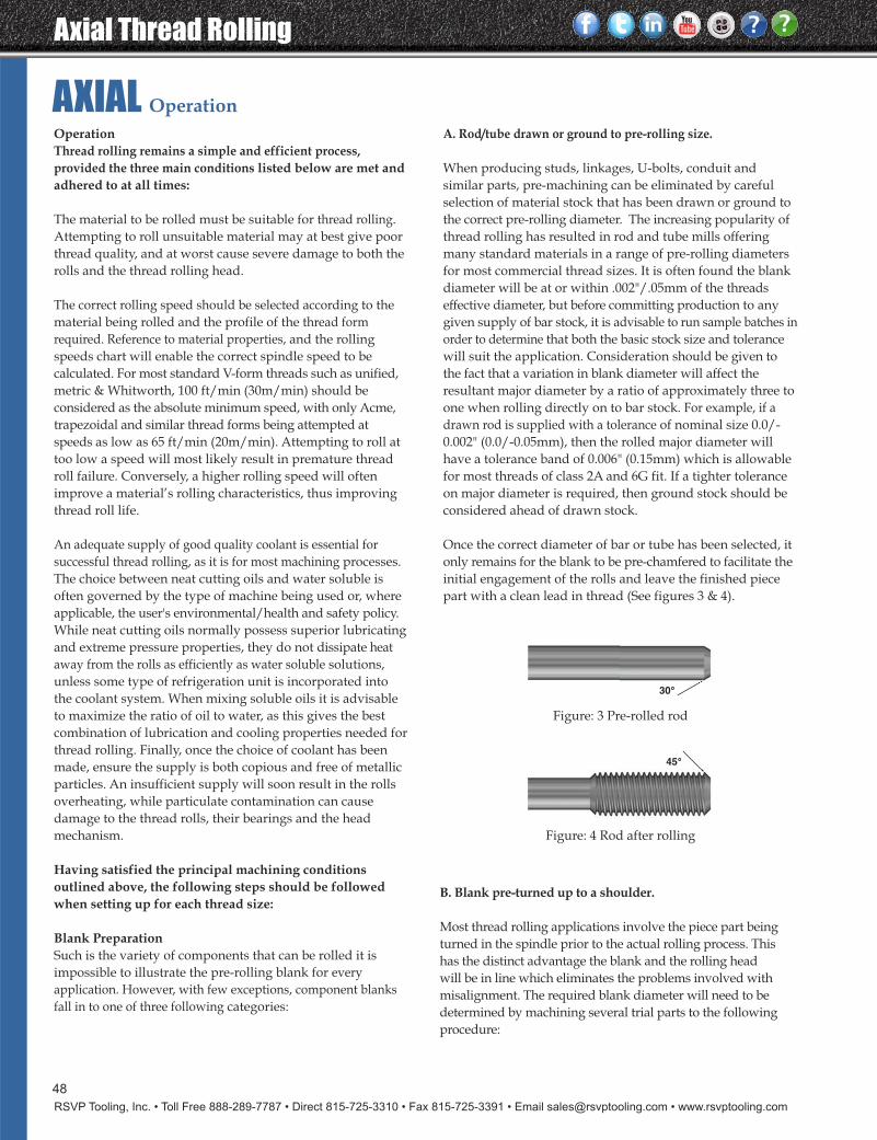
Axial Thread Rolling
RSVP Tooling, Inc. • Toll Free 888-289-7787 • Direct 815-725-3310 • Fax 815-725-3391 • Email [email protected] • www.rsvptooling.com
48
OperationThread rolling remains a simple and efficient process,provided the three main conditions listed below are met andadhered to at all times:
The material to be rolled must be suitable for thread rolling.Attempting to roll unsuitable material may at best give poorthread quality, and at worst cause severe damage to both therolls and the thread rolling head.
The correct rolling speed should be selected according to thematerial being rolled and the profile of the thread formrequired. Reference to material properties, and the rollingspeeds chart will enable the correct spindle speed to be calculated. For most standard V-form threads such as unified,metric & Whitworth, 100 ft/min (30m/min) should be considered as the absolute minimum speed, with only Acme,trapezoidal and similar thread forms being attempted atspeeds as low as 65 ft/min (20m/min). Attempting to roll attoo low a speed will most likely result in premature threadroll failure. Conversely, a higher rolling speed will often improve a material’s rolling characteristics, thus improvingthread roll life.
An adequate supply of good quality coolant is essential forsuccessful thread rolling, as it is for most machining processes.The choice between neat cutting oils and water soluble isoften governed by the type of machine being used or, whereapplicable, the user's environmental/health and safety policy.While neat cutting oils normally possess superior lubricatingand extreme pressure properties, they do not dissipate heataway from the rolls as efficiently as water soluble solutions,unless some type of refrigeration unit is incorporated intothe coolant system. When mixing soluble oils it is advisableto maximize the ratio of oil to water, as this gives the bestcombination of lubrication and cooling properties needed forthread rolling. Finally, once the choice of coolant has beenmade, ensure the supply is both copious and free of metallicparticles. An insufficient supply will soon result in the rollsoverheating, while particulate contamination can causedamage to the thread rolls, their bearings and the headmechanism.
Having satisfied the principal machining conditions outlined above, the following steps should be followedwhen setting up for each thread size:
Blank PreparationSuch is the variety of components that can be rolled it is impossible to illustrate the pre-rolling blank for everyapplication. However, with few exceptions, component blanksfall in to one of three following categories:
A. Rod/tube drawn or ground to pre-rolling size.
When producing studs, linkages, U-bolts, conduit and similar parts, pre-machining can be eliminated by carefulselection of material stock that has been drawn or ground tothe correct pre-rolling diameter. The increasing popularity ofthread rolling has resulted in rod and tube mills offeringmany standard materials in a range of pre-rolling diametersfor most commercial thread sizes. It is often found the blankdiameter will be at or within .002"/.05mm of the threadseffective diameter, but before committing production to anygiven supply of bar stock, it is advisable to run sample batches inorder to determine that both the basic stock size and tolerancewill suit the application. Consideration should be given tothe fact that a variation in blank diameter will affect theresultant major diameter by a ratio of approximately three toone when rolling directly on to bar stock. For example, if adrawn rod is supplied with a tolerance of nominal size 0.0/-0.002" (0.0/-0.05mm), then the rolled major diameter willhave a tolerance band of 0.006" (0.15mm) which is allowablefor most threads of class 2A and 6G fit. If a tighter toleranceon major diameter is required, then ground stock should beconsidered ahead of drawn stock.
Once the correct diameter of bar or tube has been selected, itonly remains for the blank to be pre-chamfered to facilitate theinitial engagement of the rolls and leave the finished piecepart with a clean lead in thread (See figures 3 & 4).
Figure: 3 Pre-rolled rod
Figure: 4 Rod after rolling
45°
AXIAL Operation
30°
B. Blank pre-turned up to a shoulder.
Most thread rolling applications involve the piece part beingturned in the spindle prior to the actual rolling process. Thishas the distinct advantage the blank and the rolling head will be in line which eliminates the problems involved withmisalignment. The required blank diameter will need to be determined by machining several trial parts to the followingprocedure:
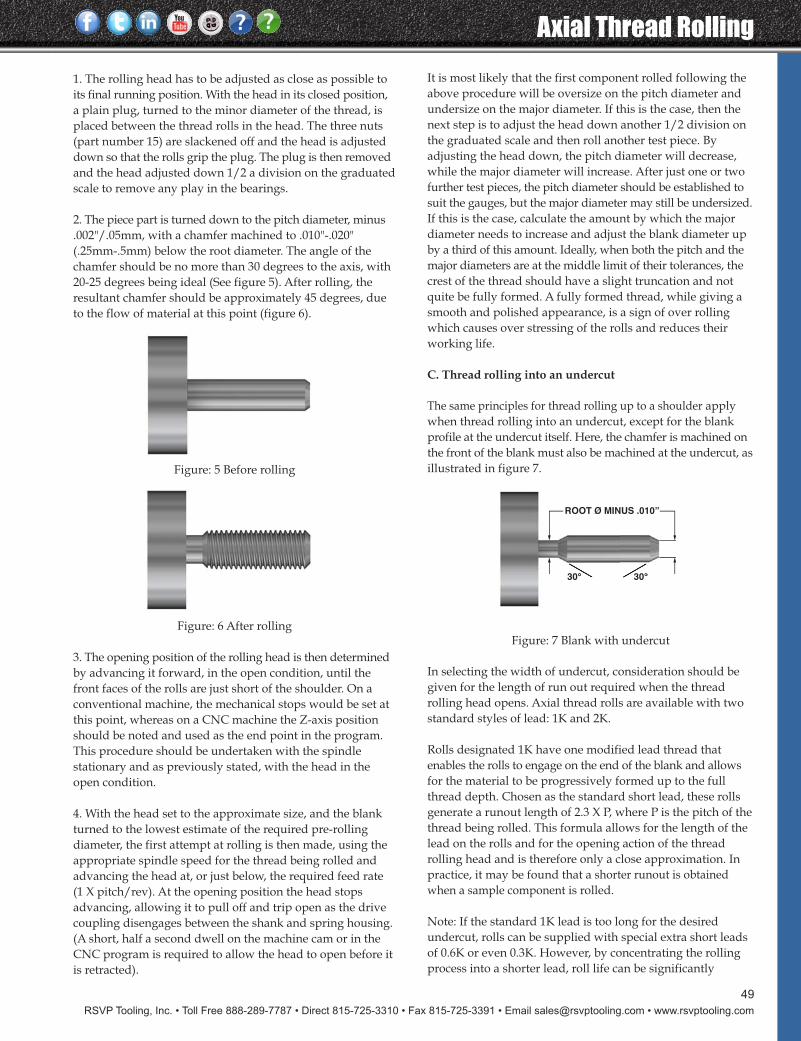
RSVP Tooling, Inc. • Toll Free 888-289-7787 • Direct 815-725-3310 • Fax 815-725-3391 • Email [email protected] • www.rsvptooling.com
Axial Thread Rolling
49
30° 30°30° 30°
ROOT Ø MINUS .010”
Figure: 7 Blank with undercut
1. The rolling head has to be adjusted as close as possible toits final running position. With the head in its closed position,a plain plug, turned to the minor diameter of the thread, isplaced between the thread rolls in the head. The three nuts(part number 15) are slackened off and the head is adjusteddown so that the rolls grip the plug. The plug is then removedand the head adjusted down 1/2 a division on the graduatedscale to remove any play in the bearings.
2. The piece part is turned down to the pitch diameter, minus.002"/.05mm, with a chamfer machined to .010"-.020"(.25mm-.5mm) below the root diameter. The angle of thechamfer should be no more than 30 degrees to the axis, with20-25 degrees being ideal (See figure 5). After rolling, theresultant chamfer should be approximately 45 degrees, dueto the flow of material at this point (figure 6).
Figure: 5 Before rolling
Figure: 6 After rolling
3. The opening position of the rolling head is then determinedby advancing it forward, in the open condition, until thefront faces of the rolls are just short of the shoulder. On aconventional machine, the mechanical stops would be set atthis point, whereas on a CNC machine the Z-axis positionshould be noted and used as the end point in the program.This procedure should be undertaken with the spindlestationary and as previously stated, with the head in theopen condition.
4. With the head set to the approximate size, and the blankturned to the lowest estimate of the required pre-rollingdiameter, the first attempt at rolling is then made, using theappropriate spindle speed for the thread being rolled andadvancing the head at, or just below, the required feed rate(1 X pitch/rev). At the opening position the head stopsadvancing, allowing it to pull off and trip open as the drivecoupling disengages between the shank and spring housing.(A short, half a second dwell on the machine cam or in theCNC program is required to allow the head to open before itis retracted).
It is most likely that the first component rolled following theabove procedure will be oversize on the pitch diameter andundersize on the major diameter. If this is the case, then thenext step is to adjust the head down another 1/2 division onthe graduated scale and then roll another test piece. By adjusting the head down, the pitch diameter will decrease,while the major diameter will increase. After just one or twofurther test pieces, the pitch diameter should be established tosuit the gauges, but the major diameter may still be undersized.If this is the case, calculate the amount by which the majordiameter needs to increase and adjust the blank diameter upby a third of this amount. Ideally, when both the pitch and themajor diameters are at the middle limit of their tolerances, thecrest of the thread should have a slight truncation and notquite be fully formed. A fully formed thread, while giving asmooth and polished appearance, is a sign of over rollingwhich causes over stressing of the rolls and reduces theirworking life.
C. Thread rolling into an undercut
The same principles for thread rolling up to a shoulder applywhen thread rolling into an undercut, except for the blankprofile at the undercut itself. Here, the chamfer is machined onthe front of the blank must also be machined at the undercut, asillustrated in figure 7.
In selecting the width of undercut, consideration should begiven for the length of run out required when the threadrolling head opens. Axial thread rolls are available with twostandard styles of lead: 1K and 2K.
Rolls designated 1K have one modified lead thread that enables the rolls to engage on the end of the blank and allowsfor the material to be progressively formed up to the fullthread depth. Chosen as the standard short lead, these rollsgenerate a runout length of 2.3 X P, where P is the pitch of thethread being rolled. This formula allows for the length of thelead on the rolls and for the opening action of the threadrolling head and is therefore only a close approximation. Inpractice, it may be found that a shorter runout is obtainedwhen a sample component is rolled.
Note: If the standard 1K lead is too long for the desired undercut, rolls can be supplied with special extra short leadsof 0.6K or even 0.3K. However, by concentrating the rollingprocess into a shorter lead, roll life can be significantly
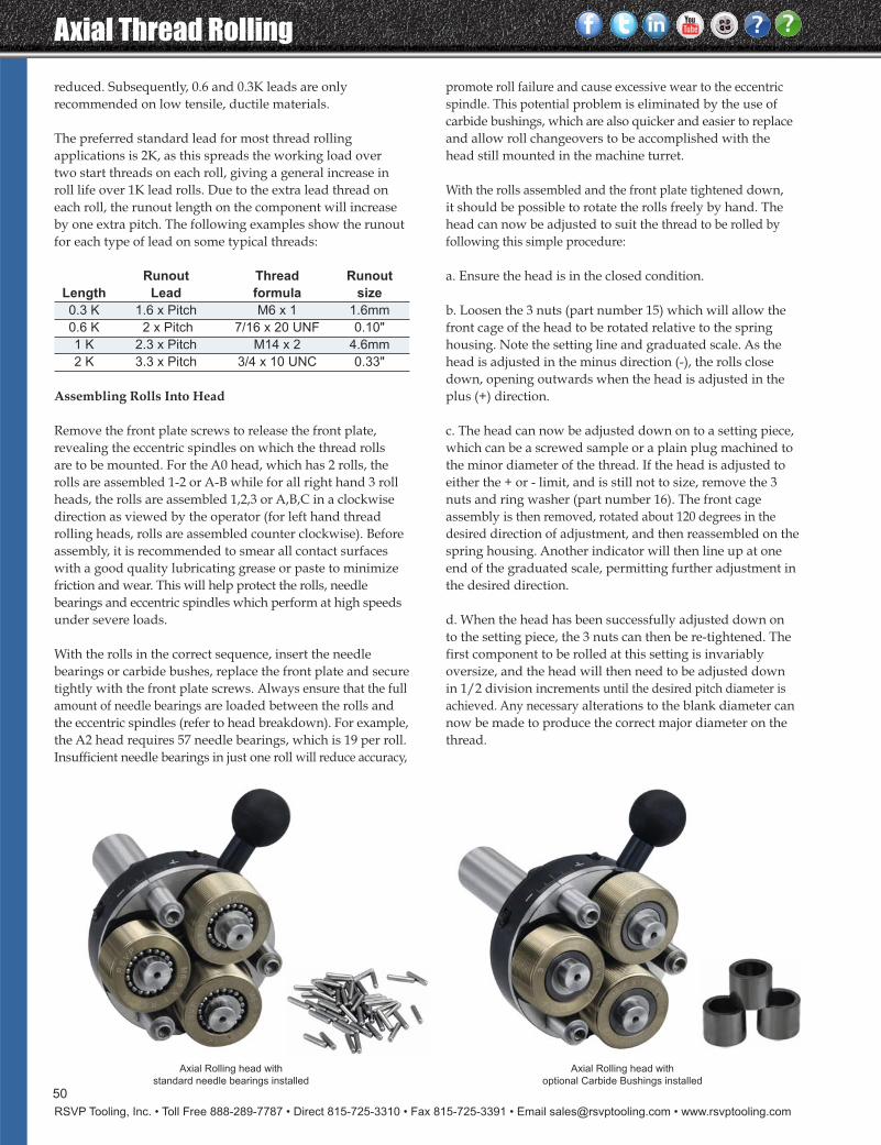
Axial Thread Rolling
RSVP Tooling, Inc. • Toll Free 888-289-7787 • Direct 815-725-3310 • Fax 815-725-3391 • Email [email protected] • www.rsvptooling.com
50
reduced. Subsequently, 0.6 and 0.3K leads are only recommended on low tensile, ductile materials.
The preferred standard lead for most thread rolling applications is 2K, as this spreads the working load overtwo start threads on each roll, giving a general increase inroll life over 1K lead rolls. Due to the extra lead thread oneach roll, the runout length on the component will increaseby one extra pitch. The following examples show the runoutfor each type of lead on some typical threads:
Runout Thread Runout
Length Lead formula size
0.3 K 1.6 x Pitch M6 x 1 1.6mm
0.6 K 2 x Pitch 7/16 x 20 UNF 0.10"
1 K 2.3 x Pitch M14 x 2 4.6mm
2 K 3.3 x Pitch 3/4 x 10 UNC 0.33"
Assembling Rolls Into Head
Remove the front plate screws to release the front plate,revealing the eccentric spindles on which the thread rollsare to be mounted. For the A0 head, which has 2 rolls, therolls are assembled 1-2 or A-B while for all right hand 3 rollheads, the rolls are assembled 1,2,3 or A,B,C in a clockwisedirection as viewed by the operator (for left hand threadrolling heads, rolls are assembled counter clockwise). Beforeassembly, it is recommended to smear all contact surfaceswith a good quality lubricating grease or paste to minimizefriction and wear. This will help protect the rolls, needle bearings and eccentric spindles which perform at high speedsunder severe loads.
With the rolls in the correct sequence, insert the needle bearings or carbide bushes, replace the front plate and securetightly with the front plate screws. Always ensure that the fullamount of needle bearings are loaded between the rolls andthe eccentric spindles (refer to head breakdown). For example,the A2 head requires 57 needle bearings, which is 19 per roll.Insufficient needle bearings in just one roll will reduce accuracy,
promote roll failure and cause excessive wear to the eccentricspindle. This potential problem is eliminated by the use ofcarbide bushings, which are also quicker and easier to replaceand allow roll changeovers to be accomplished with thehead still mounted in the machine turret.
With the rolls assembled and the front plate tightened down, it should be possible to rotate the rolls freely by hand. Thehead can now be adjusted to suit the thread to be rolled byfollowing this simple procedure:
a. Ensure the head is in the closed condition.
b. Loosen the 3 nuts (part number 15) which will allow thefront cage of the head to be rotated relative to the springhousing. Note the setting line and graduated scale. As thehead is adjusted in the minus direction (-), the rolls closedown, opening outwards when the head is adjusted in theplus (+) direction.
c. The head can now be adjusted down on to a setting piece,which can be a screwed sample or a plain plug machined tothe minor diameter of the thread. If the head is adjusted toeither the + or - limit, and is still not to size, remove the 3nuts and ring washer (part number 16). The front cageassembly is then removed, rotated about 120 degrees in thedesired direction of adjustment, and then reassembled on thespring housing. Another indicator will then line up at oneend of the graduated scale, permitting further adjustment inthe desired direction.
d. When the head has been successfully adjusted down onto the setting piece, the 3 nuts can then be re-tightened. Thefirst component to be rolled at this setting is invariablyoversize, and the head will then need to be adjusted downin 1/2 division increments until the desired pitch diameter isachieved. Any necessary alterations to the blank diameter cannow be made to produce the correct major diameter on thethread.
Axial Rolling head with
standard needle bearings installed
Axial Rolling head with
optional Carbide Bushings installed
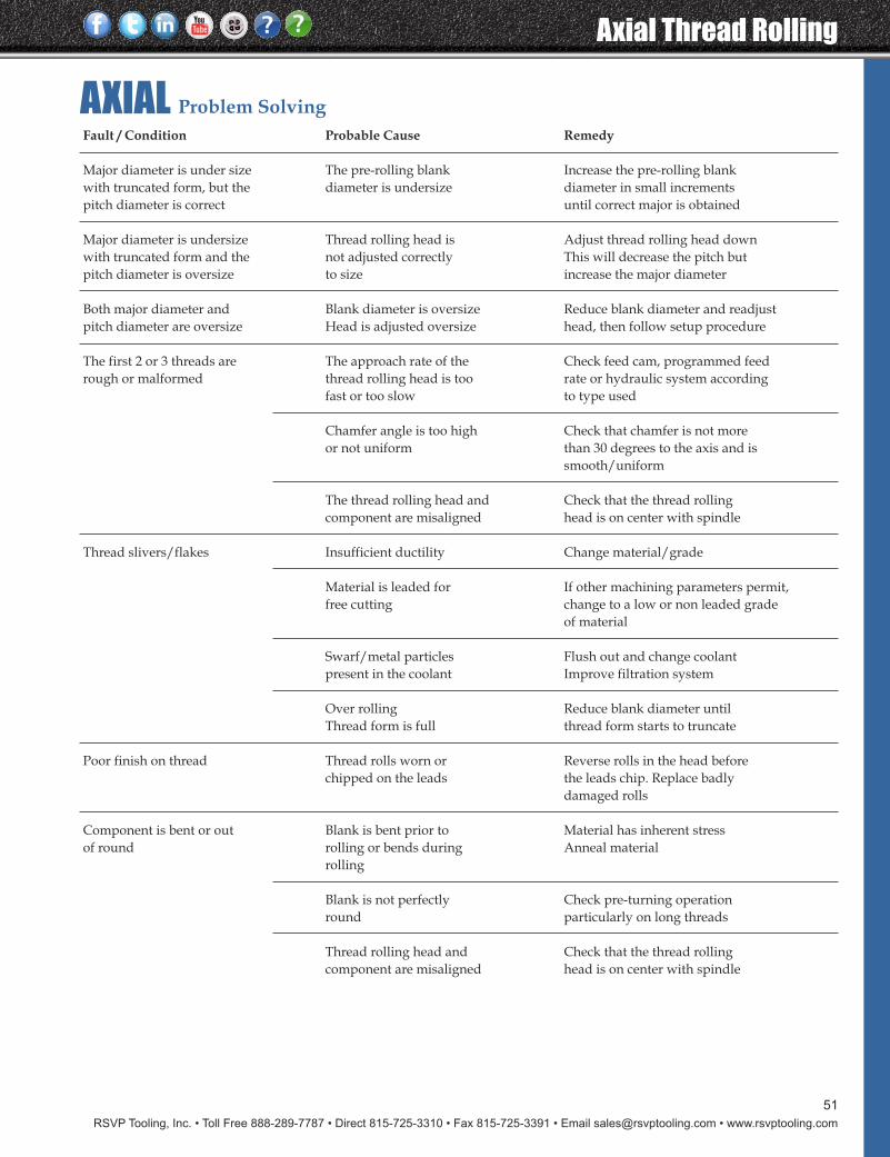
RSVP Tooling, Inc. • Toll Free 888-289-7787 • Direct 815-725-3310 • Fax 815-725-3391 • Email [email protected] • www.rsvptooling.com
Axial Thread Rolling
51
Fault / Condition Probable Cause Remedy
Major diameter is under size The pre-rolling blank Increase the pre-rolling blankwith truncated form, but the diameter is undersize diameter in small incrementspitch diameter is correct until correct major is obtained
Major diameter is undersize Thread rolling head is Adjust thread rolling head downwith truncated form and the not adjusted correctly This will decrease the pitch butpitch diameter is oversize to size increase the major diameter
Both major diameter and Blank diameter is oversize Reduce blank diameter and readjust pitch diameter are oversize Head is adjusted oversize head, then follow setup procedure
The first 2 or 3 threads are The approach rate of the Check feed cam, programmed feed rough or malformed thread rolling head is too rate or hydraulic system according
fast or too slow to type used
Chamfer angle is too high Check that chamfer is not more or not uniform than 30 degrees to the axis and is
smooth/uniform
The thread rolling head and Check that the thread rolling component are misaligned head is on center with spindle
Thread slivers/flakes Insufficient ductility Change material/grade
Material is leaded for If other machining parameters permit, free cutting change to a low or non leaded grade
of material
Swarf/metal particles Flush out and change coolantpresent in the coolant Improve filtration system
Over rolling Reduce blank diameter untilThread form is full thread form starts to truncate
Poor finish on thread Thread rolls worn or Reverse rolls in the head before chipped on the leads the leads chip. Replace badly
damaged rolls
Component is bent or out Blank is bent prior to Material has inherent stressof round rolling or bends during Anneal material
rolling
Blank is not perfectly Check pre-turning operationround particularly on long threads
Thread rolling head and Check that the thread rollingcomponent are misaligned head is on center with spindle
AXIAL Problem Solving
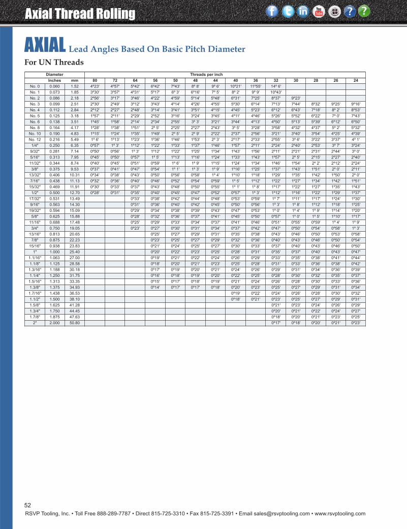
Axial Thread Rolling
RSVP Tooling, Inc. • Toll Free 888-289-7787 • Direct 815-725-3310 • Fax 815-725-3391 • Email [email protected] • www.rsvptooling.com
52
AXIAL Lead Angles Based On Basic Pitch Diameter
Diameter Threads per inch
Inches mm 80 72 64 56 50 48 44 40 36 32 30 28 26 24
No. 0 0.060 1.52 4º23' 4º57' 5º42' 6º42' 7º43' 8º 8' 9º 6' 10º21' 11º55' 14º 6'
No. 1 0.073 1.85 3º30' 3º57' 4º31' 5º17' 6º 3' 6º16' 7º 5' 8º 2' 9º 9' 10º43'
No. 2 0.086 2.18 2º56' 3º17' 3º46' 4º22' 4º59' 5º14' 5º48' 6º31' 7º25' 8º37' 9º23'
No. 3 0.099 2.51 2º30' 2º49' 3º12' 3º43' 4º14' 4º26' 4º55' 5º30' 6º14' 7º13' 7º44' 8º32' 9º25' 9º16'
No. 4 0.112 2.84 2º12' 2º27' 2º48' 3º14' 3º41' 3º51' 4º15' 4º45' 5º23' 6º12' 6º43' 7º18' 8º 2' 8º53'
No. 5 0.125 3.18 1º57' 2º11' 2º29' 2º52' 3º16' 3º24' 3º45' 4º11' 4º46' 5º26' 5º52' 6º22' 7º 0' 7º43'
No. 6 0.138 3.51 1º45' 1º58' 2º14' 2º34' 2º55' 3º 3' 3º21' 3º44' 4º13' 4º50' 5º13' 5º39' 6º12' 6º50'
No. 8 0.164 4.17 1º28' 1º38' 1º51' 2º 5' 2º25' 2º27' 2º43' 3º 5' 3º28' 3º58' 4º32' 4º37' 5º 2' 5º32'
No. 10 0.190 4.83 1º15' 1º24' 1º35' 1º49' 2º 5' 2º 9' 2º22' 2º37' 2º56' 3º21' 3º40' 3º54' 4º25' 4º39'
No. 12 0.216 5.49 1º 6' 1º13' 1º23' 1º36' 1º46' 1º53' 2º 3' 2º17' 2º33' 2º55' 3º 6' 3º22' 3º37' 4º 1'
1/4" 0.250 6.35 0º57' 1º 3' 1º12' 1º22' 1º33' 1º37' 1º46' 1º57' 2º11' 2º24' 2º40' 2º53' 3º 7' 3º24'
9/32" 0.281 7.14 0º50' 0º56' 1º 3' 1º12' 1º22' 1º25' 1º34' 1º43' 1º56' 2º11' 2º21' 2º31' 2º44' 3º 0'
5/16" 0.313 7.95 0º45' 0º50' 0º57' 1º 5' 1º13' 1º16' 1º24' 1º33' 1º43' 1º57' 2º 5' 2º15' 2º27' 2º40'
11/32" 0.344 8.74 0º40' 0º45' 0º51' 0º59' 1º 6' 1º 9' 1º15' 1º24' 1º34' 1º46' 1º54' 2º 2' 2º12' 2º24'
3/8" 0.375 9.53 0º37' 0º41' 0º47' 0º54' 1º 1' 1º 3' 1º 9' 1º16' 1º25' 1º37' 1º43' 1º51' 2º 0' 2º11'
13/32" 0.406 10.31 0º34' 0º38' 0º43' 0º50' 0º56' 0º58' 1º 4' 1º10' 1º18' 1º29' 1º35' 1º42' 1º50' 2º 0'
7/16" 0.438 11.13 0º32' 0º36' 0º40' 0º46' 0º52' 0º54' 0º59' 1º 5' 1º12' 1º22' 1º27' 1º34' 1º42' 1º51'
15/32" 0.469 11.91 0º30' 0º33' 0º37' 0º43' 0º48' 0º50' 0º55' 1º 1' 1º 8' 1º17' 1º22' 1º27' 1º35' 1º43'
1/2" 0.500 12.70 0º28' 0º31' 0º35' 0º40' 0º45' 0º47' 0º52' 0º57' 1º 3' 1º12' 1º16' 1º22' 1º29' 1º37'
17/32" 0.531 13.49 0º33' 0º38' 0º42' 0º44' 0º48' 0º53' 0º59' 1º 7' 1º11' 1º17' 1º24' 1º30'
9/16" 0.563 14.30 0º31' 0º36' 0º40' 0º42' 0º45' 0º50' 0º56' 1º 3' 1º 8' 1º12' 1º18' 1º25'
19/32" 0.594 15.09 0º29' 0º34' 0º38' 0º39' 0º43' 0º47' 0º53' 1º 0' 1º 4' 1º 9' 1º14' 1º20'
5/8" 0.625 15.88 0º28' 0º32' 0º36' 0º37' 0º41' 0º45' 0º50' 0º57' 1º 0' 1º 5' 1º10' 1º17'
11/16" 0.688 17.48 0º25' 0º29' 0º33' 0º34' 0º37' 0º41' 0º46' 0º51' 0º55' 0º59' 1º 4' 1º 9'
3/4" 0.750 19.05 0º23' 0º27' 0º30' 0º31' 0º34' 0º37' 0º42' 0º47' 0º50' 0º54' 0º58' 1º 3'
13/16" 0.813 20.65 0º25' 0º27' 0º29' 0º31' 0º35' 0º38' 0º43' 0º46' 0º50' 0º53' 0º58'
7/8" 0.875 22.23 0º23' 0º25' 0º27' 0º29' 0º32' 0º36' 0º40' 0º43' 0º46' 0º50' 0º54'
15/16" 0.938 23.83 0º21' 0º24' 0º25' 0º27' 0º30' 0º33' 0º37' 0º40' 0º43' 0º46' 0º50'
1" 1.000 25.40 0º20' 0º22' 0º23' 0º25' 0º28' 0º31' 0º35' 0º37' 0º40' 0º43' 0º47'
1.1/16" 1.063 27.00 0º19' 0º21' 0º22' 0º24' 0º26' 0º29' 0º33' 0º35' 0º38' 0º41' 0º44'
1.1/8" 1.125 28.58 0º18' 0º20' 0º21' 0º23' 0º25' 0º28' 0º31' 0º33' 0º36' 0º38' 0º42'
1.3/16" 1.188 30.18 0º17' 0º19' 0º20' 0º21' 0º24' 0º26' 0º29' 0º31' 0º34' 0º36' 0º39'
1.1/4" 1.250 31.75 0º16' 0º18' 0º19' 0º20' 0º22' 0º25' 0º28' 0º30' 0º32' 0º35' 0º37'
1.5/16" 1.313 33.35 0º15' 0º17' 0º18' 0º19' 0º21' 0º24' 0º26' 0º28' 0º30' 0º33' 0º36'
1.3/8" 1.375 34.93 0º14' 0º17' 0º17' 0º18' 0º20' 0º23' 0º25' 0º27' 0º29' 0º31' 0º34'
1.7/16" 1.438 36.53 0º19' 0º22' 0º24' 0º26' 0º28' 0º30' 0º32'
1.1/2" 1.500 38.10 0º18' 0º21' 0º23' 0º25' 0º27' 0º29' 0º31'
1.5/8" 1.625 41.28 0º21' 0º23' 0º24' 0º26' 0º29'
1.3/4" 1.750 44.45 0º20' 0º21' 0º22' 0º24' 0º27'
1.7/8" 1.875 47.63 0º18' 0º20' 0º21' 0º23' 0º25'
2" 2.000 50.80 0º17' 0º18' 0º20' 0º21' 0º23'
For UN Threads
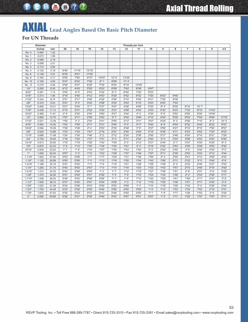
RSVP Tooling, Inc. • Toll Free 888-289-7787 • Direct 815-725-3310 • Fax 815-725-3391 • Email [email protected] • www.rsvptooling.com
Axial Thread Rolling
53
AXIAL Lead Angles Based On Basic Pitch Diameter
Diameter Threads per inch
Inches mm 20 18 16 14 13 12 11 10 9 8 7 6 5 4.5
No. 0 0.060 1.52
No. 1 0.073 1.85
No. 2 0.086 2.18
No. 3 0.099 2.51
No. 4 0.112 2.84
No. 5 0.125 3.18 9º46' 11º16' 13º18'
No. 6 0.138 3.51 8º35' 9º51' 11º30'
No. 8 0.164 4.17 6º55' 7º50' 9º10' 10º57' 12º 9' 13º36'
No. 10 0.190 4.83 5º47' 6º34' 7º36' 9º 1' 9º56' 11º 4'
No. 12 0.216 5.49 4º58' 5º37' 6º28' 7º39' 8º24' 9º19' 10º29'
1/4" 0.250 6.35 4º12' 4º43' 5º26' 6º23' 6º59' 7º43' 8º38' 9º47'
9/32" 0.281 7.14 3º40' 4º 9' 4º43' 5º32' 6º 3' 6º40' 7º26' 8º23'
5/16" 0.313 7.95 3º15' 3º40' 4º12' 4º53' 5º20' 5º52' 6º32' 7º20' 8º23' 9º46'
11/32" 0.344 8.74 2º51' 3º17' 3º46' 4º26' 4º46' 5º15' 5º49' 6º31' 7º26' 8º38'
3/8" 0.375 9.53 2º47' 3º 0' 3º24' 3º58' 4º20' 4º43' 5º15' 5º52' 6º40' 7º44'
13/32" 0.406 10.31 2º27' 2º44' 3º 7' 3º37' 3º47' 4º26' 4º46' 5º20' 6º 3' 6º59' 8º16' 10º 7'
7/16" 0.438 11.13 2º15' 2º31' 2º53' 3º20' 3º37' 3º58' 4º24' 4º53' 5º32' 6º23' 7º32' 9º10' 11º43'
15/32" 0.469 11.91 2º 5' 2º20' 2º40' 3º60' 3º21' 3º40' 4º 3' 4º30' 5º 6' 5º52' 6º55' 8º26' 10º40'
1/2" 0.500 12.70 1º57' 2º11' 2º29' 2º53' 3º 7' 3º24' 3º46' 4º12' 4º43' 5º26' 6º23' 7º44' 9º46' 11º16'
17/32" 0.531 13.49 1º50' 2º 3' 2º20' 2º41' 2º55' 3º12' 3º31' 3º57' 4º24' 5º 3' 5º56' 7º10' 9º 2' 10º 3'
9/16" 0.563 14.30 1º43' 1º55' 2º11' 2º31' 2º44' 3º 0' 3º17' 3º40' 4º 9' 4º44' 5º32' 6º40' 8º23' 9º37'
19/32" 0.594 15.09 1º38' 1º49' 2º 4' 2º23' 2º35' 2º49' 3º 6' 3º27' 3º59' 4º27' 5º12' 6º15' 7º50' 8º57'
5/8" 0.625 15.88 1º33' 1º43' 1º57' 2º15' 2º27' 2º40' 2º56' 3º15' 3º40' 4º11' 4º53' 5º52' 7º20' 8º23'
11/16" 0.688 17.48 1º24' 1º34' 1º46' 2º 2' 2º12' 2º24' 2º38' 2º56' 3º17' 3º46' 4º24' 5º14' 6º31' 7º26'
3/4" 0.750 19.05 1º16' 1º25' 1º37' 1º51' 2º 0' 2º11' 2º24' 2º40' 3º 0' 3º24' 3º58' 4º43' 5º52' 6º40'
13/16" 0.813 20.65 1º10' 1º18' 1º29' 1º42' 1º50' 2º 0' 2º12' 2º27' 2º44' 3º 7' 3º37' 4º20' 5º20' 6º 3'
7/8" 0.875 22.23 1º 5' 1º12' 1º22' 1º34' 1º42' 1º51' 2º 2' 2º15' 2º32' 2º53' 3º20' 3º28' 4º53' 5º32'
15/16" 0.938 23.83 1º 1' 1º 8' 1º16' 1º27' 1º35' 1º43' 1º54' 2º 5' 2º20' 2º40' 3º 6' 3º40' 4º30' 5º 6'
1" 1.000 25.40 0º57' 1º 3' 1º12' 1º22' 1º29' 1º37' 1º46' 1º57' 2º11' 2º29' 2º53' 3º24' 4º12' 4º44
1.1/16" 1.063 27.00 0º53' 0º59' 1º 7' 1º17' 1º24' 1º31' 1º39' 1º56' 2º 3' 2º20' 2º41' 3º12' 3º55' 4º24'
1.1/8" 1.125 28.58 0º50' 0º56' 1º 3' 1º13' 1º18' 1º25' 1º34' 1º43' 1º56' 2º11' 2º32' 3º 0' 3º40' 4º 8'
1.3/16" 1.188 30.18 0º47' 0º53' 1º 0' 1º 9' 1º14' 1º21' 1º28' 1º38' 1º49' 2º 4' 2º23' 2º49' 3º27' 3º53'
1.1/4" 1.250 31.75 0º45' 0º50' 0º57' 1º 5' 1º10' 1º16' 1º24' 1º33' 1º43' 1º57' 2º15' 2º40' 3º15' 3º40'
1.5/16" 1.313 33.35 0º43' 0º48' 0º54' 1º 2' 1º 7' 1º12' 1º19' 1º27' 1º38' 1º51' 2º 8' 2º31' 3º 6' 3º29'
1.3/8" 1.375 34.93 0º41' 0º45' 0º51' 0º59' 1º 4' 1º 9' 1º15' 1º24' 1º34' 1º46' 2º 2' 2º24' 2º56' 3º17'
1.7/16" 1.438 36.53 0º39' 0º43' 0º49' 0º56' 1º 1' 1º 6' 1º12' 1º20' 1º29' 1º41' 1º56' 2º17' 2º47' 3º 8'
1.1/2" 1.500 38.10 0º37' 0º42' 0º47' 0º54' 0º58' 1º 3' 1º 9' 1º16' 1º25' 1º36' 1º51' 2º11' 2º40' 3º 0'
1.5/8" 1.625 41.28 0º34' 0º38' 0º43' 0º50' 0º53' 0º58' 1º 4' 1º10' 1º18' 1º29' 1º42' 2º 0' 2º26' 2º44'
1.3/4" 1.750 44.45 0º32' 0º36' 0º40' 0º46' 0º50' 0º54' 0º59' 1º 5' 1º12' 1º22' 1º34' 1º52' 2º15' 2º31'
1.7/8" 1.875 47.63 0º30' 0º33' 0º37' 0º43' 0º46' 0º50' 0º55' 1º 1' 1º 8' 1º17' 1º28' 1º43' 2º 5' 2º20'
2" 2.000 50.80 0º28' 0º31' 0º35' 0º40' 0º43' 0º47' 0º51' 0º57' 1º 3' 1º11' 1º22' 1º37' 1º57' 2º11'
For UN Threads

Axial Thread Rolling
RSVP Tooling, Inc. • Toll Free 888-289-7787 • Direct 815-725-3310 • Fax 815-725-3391 • Email [email protected] • www.rsvptooling.com
54
Diameter Pitch
mm inches 0.30 0.35 0.40 0.45 0.50 0.60 0.70 0.75 0.80 1.00 1.25
1.4 0.055 4º 32' 5º 26' 6º 22' 7º 22'
1.6 0.063 3º 53' 4º 38' 5º 26' 6º 15' 7º 7'
1.8 0.071 3º 24' 4º 3' 4º 44' 5º 26' 6º 9'
2.0 0.079 3º 2' 3º 36' 4º 11' 4º 48' 5º 26' 6º 46'
2.2 0.087 2º 44' 3º 14' 3º 45' 4º 18' 4º 51' 6º 1' 7º 17'
2.5 0.098 2º 22' 2º 48' 3º 15' 3º 43' 4º 11' 5º 10' 6º 13' 6º 46' 7º 20'
3.0 0.118 1º 57' 2º 18' 2º 40' 3º 2' 3º 24' 4º 11' 5º 0' 5º 26' 5º 52'
3.5 0.138 1º 39' 1º 57' 2º 15' 2º 33' 2º 52' 3º 31' 4º 11' 4º 32' 4º 53' 6º 22'
4.0 0.157 1º 26' 1º 41' 1º 57' 2º 13' 2º 29' 3º 2' 3º 36' 3º 53' 4º 11' 5º 26' 7º 7'
4.5 0.177 1º 16' 1º 30' 1º 43' 1º 57' 2º 11' 2º 40' 3º 9' 3º 24' 3º 40' 4º 44' 6º 9'
5.0 0.197 1º 8' 1º 20' 1º 32' 1º 45' 1º 57' 2º 22' 2º 48' 3º 2' 3º 15' 4º 11' 5º 26'
6.0 0.236 0º 57' 1º 6' 1º 16' 1º 26' 1º 36' 1º 57' 2º 18' 2º 29' 2º 40' 3º 24' 4º 23'
6.3 0.248 0º 54' 1º 3' 1º 12' 1º 22' 1º 32' 1º 51' 2º 11' 2º 21' 2º 31' 3º 13' 4º 9'
8.0 0.315 0º 42' 0º 49' 0º 57' 1º 4' 1º 11' 1º 26' 1º 41' 1º 49' 1º 57' 2º 29' 3º10'
10.0 0.394 0º 33' 0º 39' 0º 45' 1º 51' 0º 57' 1º 8' 1º 20' 1º 26' 1º 32' 1º 57' 2º 29'
12.0 0.472 0º 28' 0º 33' 0º 37' 0º 42' 0º 47' 0º 57' 1º 6' 1º 11' 1º 16' 1º 36' 2º 2'
14.0 0.551 0º 24' 0º 28' 0º 32' 0º 36' 0º 40' 0º 48' 0º 57' 1º 1' 1º 5' 1º 22' 1º 44'
16.0 0.630 0º 21' 0º 24' 0º 28' 0º 31' 0º 35' 0º 42' 0º 49' 0º 53' 0º 57' 1º 11' 1º 30'
18.0 0.709 0º 22' 0º 25' 0º 28' 0º 31' 0º 37' 0º 44' 0º 47' 0º 50' 1º 3' 1º 20'
20.0 0.787 0º 22' 0º 25' 0º 28' 0º 33' 0º 39' 0º 42' 0º 45' 0º 57' 1º 11'
22.0 0.866 0º 20' 0º 23' 0º 25' 0º 30' 0º 36' 0º 38' 0º 41' 0º 51' 1º 5'
24.0 0.945 0º 21' 0º 23' 0º 28' 0º 33' 0º 35' 0º 37' 0º 47' 0º 59'
27.0 1.063 0º 21' 0º 25' 0º 29' 0º 31' 0º 33' 0º 42' 0º 52'
30.0 1.181 0º 22' 0º 26' 0º 28' 0º 30' 0º 37' 0º 47'
33.0 1.299 0º 20' 0º 24' 0º 25' 0º 27' 0º 34' 0º 42'
36.0 1.417 0º 22' 0º 23' 0º 25' 0º 31' 0º 39'
39.0 1.535 0º 20' 0º 21' 0º 23' 0º 29' 0º 36'
42.0 1.654 0º 20' 0º 21' 0º 26' 0º 33'
45.0 1.772 0º 20' 0º 25' 0º 31'
48.0 1.890 0º 23' 0º 29'
52.0 2.047 0º 21' 0º 27'
Diameter Pitch
mm inches 1.50 1.75 2.00 2.50 3.00 3.50 4.00 4.50 5.00 5.50 6.00
1.4 0.055
1.6 0.063
1.8 0.071
2.0 0.079
2.2 0.087
2.5 0.098
3.0 0.118
3.5 0.138
4.0 0.157
4.5 0.177
5.0 0.197 6º 46'
6.0 0.236 5º 26' 6º 32'
6.3 0.248 5º 7' 6º 9' 7º 15'
8.0 0.315 3º 53' 4º 38' 5º 26' 7º 7'
10.0 0.394 3º 2' 3º 36' 4º 11' 5º 26' 6º 46'
12.0 0.472 2º 29' 2º 56' 3º 24' 4º 23' 5º 26' 6º 32'
14.0 0.551 2º 6' 2º 29' 2º 52' 3º 41' 4º 32' 5º 26' 6º 22' 7º 22'
16.0 0.630 1º 49' 2º 9' 2º 29' 3º 10' 3º 53' 4º 38' 5º 26' 6º 15' 7º 7'
18.0 0.709 1º 36' 1º 54' 2º 11' 2º 47' 3º 24' 4º 3' 4º 44' 5º 26' 6º 9' 6º 55'
22.0 0.866 1º 18' 1º 32' 1º 46' 2º 14' 2º 44' 3º 14' 3º 45' 4º 18' 4º 51' 5º 26' 6º 1'
24.0 0.945 1º 11' 1º 24' 1º 36' 2º 2' 2º 29' 2º 56' 3º 24' 3º 53' 4º 23' 4º 54' 5º 26'
27.0 1.063 1º 3' 1º 14' 1º 25' 1º 48' 2º 11' 2º 35' 2º 59' 3º 24' 3º 50' 4º 16' 4º 44'
30.0 1.181 0º 57' 1º 6' 1º 16' 1º 36' 1º 57' 2º 18' 2º 40' 3º 2' 3º 24' 3º 47' 4º 11'
33.0 1.299 0º 51' 1º 0' 1º 9' 1º 27' 1º 46' 2º 5' 2º 24' 2º 44' 3º 4' 3º 24' 3º 45'
36.0 1.417 0º 47' 0º 55' 1º 3' 1º 20' 1º 36' 1º 54' 2º 11' 2º 29' 2º 47' 3º 5' 3º 24'
39.0 1.535 0º 43' 0º 51' 0º 58' 1º 13' 1º 29' 1º 44' 2º 0' 2º 16' 2º 33' 2º 50' 3º 7'
42.0 1.654 0º 40' 0º 47' 0º 54' 1º 8' 1º 22' 1º 36' 1º 51' 2º 6' 2º 21' 2º 37' 2º 52'
45.0 1.772 0º 37' 0º 44' 0º 50' 1º 3' 1º 16' 1º 30' 1º 43' 1º 57' 2º 11' 2º 25' 2º 40'
48.0 1.890 0º 35' 0º 41' 0º 47' 0º 59' 1º 11' 1º 24' 1º 36' 1º 49' 2º 2' 2º 15' 2º 29'
52.0 2.047 0º 32' 0º 38' 0º43' 0º 54' 1º 6' 1º 17' 1º 29' 1º 40' 1º 52'
AXIAL Lead Angles Based On Basic Pitch DiameterFor Metric Screw Threads M Profile
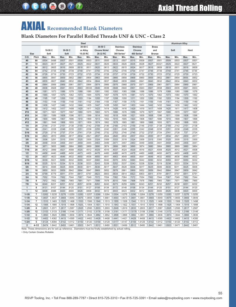
RSVP Tooling, Inc. • Toll Free 888-289-7787 • Direct 815-725-3310 • Fax 815-725-3391 • Email [email protected] • www.rsvptooling.com
Axial Thread Rolling
55
AXIAL Recommended Blank Diameters
Steel Aluminum Alloy
30-50 C 30-50 C Stainless Stainless Brass
10-50 C 30-50 C or Alloy Chrome Nickel Chrome Chrome and Soft Hard
Size Soft Soft 15-25 RC 26-32 RC 300 Series* 400 Series* Bronze
O.D. Pitch Max. Min. Max. Min. Max. Min. Max. Min. Max. Min. Max. Min. Max. Min. Max. Min. Max. Min.
#0 80 .0504 .0498 .0507 .0501 .0509 .0503 .0511 .0505 .0513 .0507 .0515 .0509 .0507 .0501 .0509 .0503 .0507 .0501
#1 72 .0623 .0617 .0627 .0621 .0629 .0622 .0631 .0625 .0633 .0626 .0635 .0628 .0627 .06321 .0629 .0622 .0627 0621
#1 64 .0612 .0605 .0616 .0609 .0618 .0611 .0620 .0613 .0622 .0615 .0624 .0617 .0616 .0609 .0618 .0611 .0616 .0609
#2 64 .0742 .0735 .0746 .0739 .0748 .0741 .0750 .0743 .0752 .0745 .0754 .0747 .0746 .0739 .0748 .0741 .0746 0739
#2 56 .0726 .0719 .0730 .0723 .0732 .0725 .0734 .0728 .0737 .0730 .0739 .0732 .0730 .0723 .0732 .0725 .0730 .0723
#3 56 .0855 .0847 .0859 .0852 .0861 .0854 .0863 .0856 .0866 .0858 .0868 .0860 .0859 .0852 .0861 .0854 .0859. .0852
#3 48 .0835 .0827 .0840 .0832 .0842 .0834 .0844 .0837 .0846 .0839 .0849 .0841 .0840 .0832 .0842 .0834 .0840 .0832
#4 48 .0964 .0956 .0969 .0961 .0971 .0964 .0974 .0966 .0976 .0968 .0979 .0971 .0969 .0961 .0971 .0964 .0969 .0961
#4 40 .0936 .0928 .0941 .0933 .0943 .09335 .0946 .0938 .0948 .0940 .0951 .0943 .0941 .0938 .0943 .0935 .0941 .0933
#5 44 .1081 .1073 .1086 .1078 .1088 .1080 .1091 .1082 .1093 .1085 .1096 .1088 .1086 .1078 .1088 .1080 .1086 .1078
#5 40 .1065 .1057 .1070 .1062 .1073 .1064 .1075 .1067 .1078 .1070 .1081 .1072 .1070 .1062 .1073 .1064 .1070 .1062
#6 40 .1195 .1187 .1200 .1192 .1203 .1194 .1205 .1197 .1208 .1200 .1211 .1202 .1200 .1192 .1203 .1194 .1200 .1192
#6 32 .1153 .1144 .1159 .1149 .1161 .1152' .1164 .1155 .1167 .1158 .1170 .1161 .1159 .1149 .1161 .1152 .1159 .1149
#8 36 .1436 .1427 .1442 .1432 .1444 .1435 .1447 .1438 .1450 .1441 .1453 .1444 .1442 .1432 .1444 .1435 .1442 .1432
#8 32 .1412 .1402 .1417 .1408 .1420 .1411 .1423 .1414 .1426 .1416 .1429 .1419 .1417 .1408 .1420 .1411 .1417 .1408
#10 32 .1671 .1661 .1677 .1667 .1680 .1670 .1683 .1673 .1686 .1676 .1689 .1679 .1677 .1667 .1680 .1670 .1677 .1667
#10 24 .1591 .1589 .1608 .1596 .1611 .1599 .1614 .1602 .1618 .1606 .1621 .1609 .1608 .1596 .1611 .1599 .1608 .1596
#12 28 .1900 .1889 .1907 .1896 .1910 .1899 .1913 .1902 .1916 .1905 .1920 .1908 .1907 .1896 .1910 .1899 .1907 .1896
#12 24 .1861 .1848 .1868 .1855 .1871 .1859 .1874 .1862 .1878 .1865 .1881 .1869 .1868 .1855 .1871 .1859 .1868 .1855
1/4 20 .2144 .2131 .2151 .2138 .2155 .2142 .2159 .2146 .2166 .2153 .2159 .2146 .2151 .2138 .2155 .2142 .2151 .2138
1/4 28 .2241 .2228 .2248 .2235 .2251 .2238 .2255 .2242 .2261 .2248 .2255 .2242 .2248 .2235 .2251 .2238 .2248 .2235
5/16 18 .2729 .2716 .2737 .2724 .2741 .2728 .2745 .2732 .2753 .2740 .2745 .2732 .2737 .2724 .2741 .2728 .737 .2724
5/16 24 .2823 .2810 .2830 .2817 .2834 .2821 .2837 .2824 .2845 .2832 .2837 .2824 .2830 .2817 .2834 .2821 .2830 .2817
3/8 16 .3306 .3291 .3315 .3300 .3320 .3305 .3324 .3309 .3333 .3318 .3324 .3309 .3315 .3300 .3320 .3305 .3315 .3300
3/8 24 .3448 .3434 .3455 .3441 .3459 .3445 .3463 .3449 .3471 .3457 .3463 .3449 .3455 .3441 .3459 .3445 .3455 .3441
7/16 14 .3871 .3855 .3880 .3864 .3885 .3869 .3890 .3874 .3899 .3883 .3890 .3874 .3880 .3864 .3885 .3869 .3880 .3864
7/16 20 .4012 .3999 .4021 .4008 .4025 .4012 .4029 .4016 .4037 .4024 .4029 .4016 .4021 .4008 .4025 .4012 .4021 .4008
1/2 13 .4458 .4440 .4468 .4450 .4473 .4455 .4478 .4460 .4488 .4470 .4478 .4460 .4468 .4450 .4473 .4455 .4468 .4450
1/2 20 .4637 .4623 .4646 .4632 .4650 .4636 .4655 .4641 .4663 .4649 .4655 .4641 .4646 .4632 .4650 .4636 .4646 .4632
9/16 12 .5039 .5021 .5050 .5032 .5055 .5037 .5060 .5042 .5070 .5052 .5060 .5042 .5050 .5032 .5055 .5037 .5050 .5032
9/16 18 .5225 .5210 .5234 .5219 .5238 .5223 .5243 .5228 .5252 .5237 .5243 .5228 .5234 .5219 .5238 .5223 .5234 .5219
5/8 11 .5614 .5595 .5625 .5606 .5630 .5611 .5636 .5617 .5647 .5628 .5636 .5617 .5625 .5606 .5630 5611 .5625 .5606
5/8 18 .5850 .5833 .5859 .5842 .5864 .5847 .5869 .5852 .5878 .5861 .5869 .5852 .5859 .5842 .5864 .5847 .5859 .5842
3/4 10 .6799 .6779 .6811 .6791 .6817 .6797 .6823 .6803 .6834 .6814 .6823 .6803 .6811 .6791 .6817 .6797 .6811 .6791
3/4 16 .7052 .7034 .7062 .7044 .7067 .7049 .7072 .7054 .7082 .7064 .7072 .7054 .7062 .7044 .7067 .7049 .7062 .7044
7/8 9 .7972 .7952 .7985 .7965 .7991 .7971 .7998 .7978 .8010 .7990 .7998 .7978 .7985 .7965 .7991 .7971 .7985 .7965
7/8 14 .8240 .8221 .8251 .8232 .8257 .8238 .8262 .8243 .8273 .8259 .8262 .8243 .8251 .8232 .8257 .8238 .8251 .8232
1 8 .9131 .9107 .9144 .9120 .9151 .9127 .9158 .9134 .9172 .9148 .9158 .9134 .9144 .9120 .9151 .9127 .9144 .9120
1 12 .9408 .9388 .9420 .9400 .9426 .9406 .9432 .9412 .9443 .9423 .9432 .9412 .9420 .9400 .9426 .9406 .9420 .9400
1-1/8 7 1.0262 1.0235 1.0276 1.0250 1.0283 1.0257 1.0290 1.0264 1.0304 1.0278 1.0290 1.0264 1.0276 1.0250 1.0283 1.0257 1.0276 1.0250
1-1/8 12 1.0657 1.0637 1.0669 1.0649 1.0675 1.0655 1.0681 1.0661 1.0693 1.0673 1.0681 1.0661 1.0669 1.0649 1.0675 1.0655 1.0669 1.0649
1-1/4 7 1.1510 1.1483 1.1525 1.1498 1.1533 1.1506 1.1540 1.1513 1.1555 1.1528 1.1540 1.1513 1.1525 1.1498 1.1533 1.1506 1.1525 1.1498
1-1/4 12 1.1906 1.1885 1.1919 1.1898 1.1925, 1.1904 1.1931 1.1910 1.1943 1.1922 1.1931 1.1910 1.1919 1.1898 1.1925 1.1904 1.1919 1.1898
1-3/8 6 1.2601 1.2571 1.2617 1.2587 1.2625 1.2595 1.2633 1.2603 1.2649 1.2619 1.2633 1.2603 1.2617 1.2587 1.2625 1.2595 1.2617 1.2587
1-3/8 12 1.3153 1.3133 1.3166 1.3146 1.3171 1.3152 1.3178 1.3158 1.3191 1.3171 1.13178 1.3158 1.3166 1.3146 1.3172 1.3152 1.3166 1.3146
1-1/2 6 1.3850 1.3820 1.3866 1.3836 1.3874 1.3844 1.3882 1.3852 1.3898 1.3868 1.3882 1.3851 1.3866 1.3836 1.3874 1.3844 1.3866 1.3836
1-1/2 12 1.4402 1.4382 1.4415 1.4395 1.4422 1.4402 1.4428 1.4408 1.4441 1.4421 1.4428 1.4408 1.4415 1.4395 1.4422 1.4402 1.4415 1.4395
1-3/4 5 1.6124 1.6094 1.6142 1.6112 1.6150 1.6120 1.6159 1.6129 1.6177 1.6147 1.6159 1.6129 1.6142 1.6112 1.6150 1.6120 1.6142 1.6112
2 4-1/2 1.8474 1.8442 1.8493 1.8461 1.8503 1.8471 1.8512 1.8480 1.8531 1.8499 1.8512 1.8480 1.8442 1.8461 1.8503 1.8471 1.8442 1.8461
Note: These dimensions are for set-up reference. Diameters must be finally established by actual rolling.
• Only Certain Grades Rollable
Blank Diameters For Parallel Rolled Threads UNF & UNC - Class 2
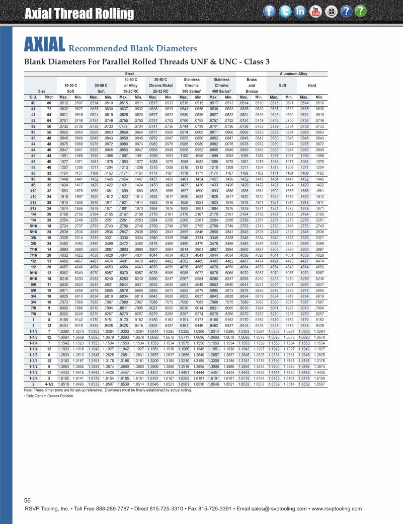
Axial Thread Rolling
RSVP Tooling, Inc. • Toll Free 888-289-7787 • Direct 815-725-3310 • Fax 815-725-3391 • Email [email protected] • www.rsvptooling.com
56
AXIAL Recommended Blank Diameters
Steel Aluminum Alloy
30-50 C 30-50 C Stainless Stainless Brass
10-50 C 30-50 C or Alloy Chrome Nickel Chrome Chrome and Soft Hard
Size Soft Soft 15-25 RC 26-32 RC 300 Series* 400 Series* Bronze
O.D. Pitch Max. Min. Max. Min. Max. Min. Max. Min. Max. Min. Max. Min. Max. Min. Max. Min. Max. Min.
#0 80 .0512 .0507 .0514 .0510 .0515 .0511 .0517 .0513 .0519 .0515 .0517 .0513 .0514 .0510 .0515 .0511 .0514 .0510
#1 72 .0632 .0627 .0635 .0630 .0637 .0632 .0638 .0633 .0641 .0636 .0638 .0633 .0635 .0630 .0637 .0632 .0635 .0630
#1 64 .0621 .0616 .0624 .0619 .0625 .0620 .0627 .0622 .0630 .0625 .0627 .0622 .0624 .0619 .0625 .0620 .0624 .0619
#2 64 .0751 .0746 .0754 .0749 .0755 .0750 .0757 .0752 .0760 .0755 .0757 .0752 .0754 .0749 .0755 .0750 .0754 .0749
#2 56 .0735 .0730 .0738 .0733 0739 .0734 .0741 .0736 .0744 .0739 .0741 .0736 .0738 .0733 .0739 .0734 .0738 .0733
#3 56 .0865 .0860 .0868 .0863 .0869 .0864 .0871 .0866 .0874 .0869 .0871 .0866 .0868 .0863 .0869 .0864 .0868 .0863
#3 48 .0845 .0840 .0848 .0843 .0850 .0845 .0852 .0847 .0855 .0850 .0852 .0847 .0848 .0843 .0850 .0845 .0848 .0843
#4 48 .0975 .0969 .0978 .0972 .0980 .0974 .0982 .0976 .0986 .0980 .0982 .0976 .0978 .0972 .0980 .0974 .0978 .0972
#4 40 .0947 .0941 .0950 .0945 .0953 .0947 .0955 .0949 .0958 .0952 .0955 .0949 .0950 .0945 .0953 .0947 .0950 .0945
#5 44 .1091 .1085 .1095 .1088 .1097 .1091 .1099 .1093 .1102 .1096 .1099 .1093 .1095 .1088 .1097 .1091 .1095 .1088
#5 40 .1077 .1071 .1081 .1075 .1083 .1077 .1085 .1079 .1088 .1082 .1085 .1079 .1081 .1075 .1083 .1077 .1081 .1075
#6 40 .1207 .1200 .1211 .1204 .1213 .1206 .1215 .1208 .1219 .1212 .1215 .1208 .1211 .1204 .1213 .1206 .1211 .1204
#6 32 .1164 .1157 .1169 .1162 .1171 .1164 .1174 .1167 .1178 .1171 .1174 .1167 .1169 .1162 .1171 .1164 .1169 .1162
#8 36 .1448 .1441 .1452 .1445 .1454 .1447 .1457 .1450 .1461 .1454 .1457 .1450 .1452 .1445 .1454 .1447 .1452 .1445
#8 32 .1424 .1417 .1429 .1422 .1431 .1424 .1433 .1426 .1437 .1430 .1433 .1426 .1429 .1422 .1431 .1424 .1429 .1422
#10 32 .1683 .1676 .1688 .1681 .1690 .1683 .1693 .1686 .1697 .1690 .1693 .1686 .1688 .1681 .1690 .1683 .1688 .1681
#10 24 .1615 .1607 .1620 .1612 .1622 .1614 .1625 .1617 .1630 .1622 .1625 .1617 .1620 .1612 .1622 .1614 .1620 .1612
#12 28 .1913 .1906 .1918 .1911 .1921 .1914 .1923 .1916 .1928 .1921 .1923 .1916 .1918 .1911 .1921 .1914 .1918 .1911
#12 24 .1874 .1866 .1879 .1871 .1881 .1873 .1884 .1876 .1889 .1881 .1884 .1876 .1879 .1871 .1881 .1873 .1879 .1871
1/4 20 .2159 .2150 .2164 .2155 .2167 .2158 .2170 .2161 .2176 .2167 .2170 .2161 .2164 .2155 .2167 .2158 .2164 .2155
1/4 28 .2254 .2246 .2259 .2251 .2261 .2253 .2264 .2256 .2269 .2261 .2264 .2256 .2259 .2251 .2261 .2253 .2259 .2251
5/16 18 .2724 .2737 .2753 .2743 .2756 .2746 .2759 .2749 .2765 .2755 .2759 .2749 .2753 .2743 .2756 .2746 .2753 .2743
5/16 24 .2839 .2830 .2845 .2836 .2847 .2838 .2850 .2841 .2855 .2846 .2850 .2841 .2845 .2836 .2847 .2838 .2845 .2836
3/8 16 .3326 .3314 .3333 .3321 .3336 .3324 .3340 .3328 .3346 .3334 .3340 .3328 .3346 .3334 .3340 .3328 .3333 .3321
3/8 24 .3463 .3453 .3469 .3459 .3472 .3462 .3475 .3465 .3480 .3470 .3475 .3465 .3469 .3459 .3472 .3462 .3469 .3459
7/16 14 .3893 .3880 .3900 .3887 .3903 .3890 .3907 .3894 .3914 .3901 .3907 .3894 .3900 .3887 .3903 .3890 .3900 .3887
7/16 20 .4032 .4022 .4038 .4028 .4041 .4031 .4044 .4034 .4051 .4041 .4044 .4034 .4038 .4028 .4041 .4031 .4038 .4028
1/2 13 .4480 .4467 .4487 .4474 .4491 .4478 .4495 .4482 .4502 .4489 .4495 .4482 .4487 .4474 .4491 .4478 .4487 .4474
1/2 20 .4657 .4646 .4664 .4653 .4654 .4643 .4670 .4659 .4676 .4665 .4670 .4659 .4664 .4653 .4654 .4643 .4664 .4653
9/16 12 .5062 .5049 .5070 .5057 .5070 .5057 .5078 .5065 .5085 .5072 .5078 .5065 .5070 .5057 .5070 .5057 .5070 .5057
9/16 18 .5246 .5233 .5253 .5240 .5253 .5240 .5260 .5247 .5267 .5254 .5260 .5247 .5253 .5240 .5253 .5240 .5253 .5240
5/8 11 .5636 .5623 .5644 .5631 .5644 .5631 .5653 .5640 .5661 .5648 .5653 .5640 .5644 .5631 .5644 .5631 .5644 .5631
5/8 18 .5871 .5858 .5878 .5865 .5878 .5865 .5885 .5872 .5892 .5879 .5885 .5872 .5878 .5865 .5878 .5865 .5878 .5865
3/4 10 .6825 .6810 .6834 .6819 .6834 .6819 .6843 .6828 .6852 .6837 .6843 .6828 .6834 .6819 .6834 .6819 .6834 .6819
3/4 16 .7073 .7060 .7080 .7067 .7080 .7067 .7088 .7075 .7096 .7083 .7088 .7075 .7080 .7067 .7080 .7067 .7087 .7067
7/8 9 .8002 .7986 .8010 .7994 .8011 .7995 .8021 .8005 .8030 .8014 .8021 .8005 .8010 .7994 .8011 .7995 .8010 .7994
7/8 14 .8262 .8249 .8270 .8257 .8270 .8257 .8279 .8266 .8287 .8274 .8279 .8266 .8270 .8257 .8270 .8257 .8270 .8257
1 8 .9160 .9142 .9170 .9151 .9170 .9152 .9180 .9162 .9191 .9173 .9180 .9162 .9170 .9152 .9170 .9152 .9170 .9152
1 12 .9434 .9419 .9443 .9428 .9428 .9415 .9452 .9437 .9461 .9446 .9452 .9437 .9443 .9428 .9428 .9415 .9443 .9428
1-1/8 7 1.0292 1.0273 1.0303 1.0284 1.0303 1.0284 1.0314 1.0295 1.0325 1.0306 1.0314 1.0295 1.0303 1.0284 1.0303 1.0284 1.0303 1.0284
1-1/8 12 1.0684 1.0669 1.0693 1.0678 1.0693 1.0678 1.0693 1.0678 1.0711 1.0696 1.0693 1.0678 1.0693 1.0678 1.0693 1.0678 1.0693 1.0678
1-1/4 7 1.1542 1.1523 1.1553 1.1534 1.1553 1.1534 1.1553 1.1534 1.1575 1.1556 1.1553 1.1534 1.1553 1.1539 1.1553 1.1534 1.1553 1.1534
1-1/4 12 1.1933 1.1918 1.1942 1.1927 1.1942 1.1927 1.1951 1.1936 1.1960 1.1945 1.1951 1.1936 1.1942 1.1927 1.1942 1.1927 1.1942 1.1927
1-3/8 6 1.2633 1.2613 1.2645 1.2625 1.2651 1.2631 1.2657 1.2637 1.2665 1.2649 1.2657 1.2637 1.2645 1.2625 1.2651 1.2631 1.2645 1.2625
1-3/8 12 1.3182 1.3167 1.3191 1.3176 1.3196 1.3181 1.3200 1.3185 1.3210 1.3195 1.3200 1.3185 1.3191 1.3176 1.3196 1.3161 1.3191 1.3176
1-1/2 6 1.3883 1.3862 1.3894 1.3874 1.3900 1.3880 1.3906 1.3886 1.3918 1.3898 1.3906 1.3886 1.3894 1.3874 1.3900 1.3880 1.3894 1.3874
1-1/2 12 1.4433 1.4416 1.4442 1.4425 1.4447 1.4430 1.4451 1.4434 1.4461 1.4444 1.4451 1.4434 1.4442 1.4425 1.4447 1.4430 1.4442 1.4435
1-3/4 5 1.6165 1.6141 1.6178 1.6154 1.6185 1.6161 1.6191 1.6167 1.6205 1.6181 1.6191 1.6167 1.6178 1.6154 1.6185 1.6161 1.6178 1.6159
2 4-1/2 1.8518 1.8493 1.8532 1.8507 1.8539 1.8514 1.8546 1.8521 1.8561 1.8536 1.8546 1.8521 1.8532 1.8507 1.8539 1.8514 1.8532 1.8507
Note: These dimensions are for set-up reference. Diameters must be finally established by actual rolling.
• Only Certain Grades Rollable
Blank Diameters For Parallel Rolled Threads UNF & UNC - Class 3
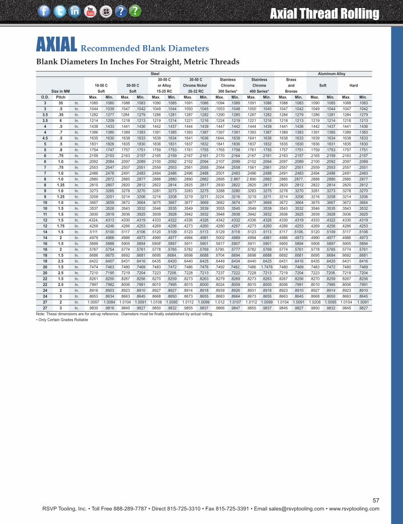
RSVP Tooling, Inc. • Toll Free 888-289-7787 • Direct 815-725-3310 • Fax 815-725-3391 • Email [email protected] • www.rsvptooling.com
Axial Thread Rolling
57
AXIAL Recommended Blank Diameters
Steel Aluminum Alloy
30-50 C 30-50 C Stainless Stainless Brass
10-50 C 30-50 C or Alloy Chrome Nickel.. Chrome Chrome and Soft Hard
Size in MM Soft Soft 15-25 RC 26-32 RC 300 Series* 400 Series* Bronze
O.D. Pitch Max. Min. Max. Min. Max. Min. Max. Min. Max. Min. Max. Min. Max. Min. Max. Min. Max. Min.
3 35 In. .1085 .1080 .1088 .1083 .1090 .1085 .1091 .1086 .1094 .1089 .1091 .1086 .1088 .1083 .1090 .1085 .1088 .1083
3 .5 In. .1044 .1039 .1047 .1042 .1049 .1044 .1050 .1045 .1053 .1048 .1050 .1045 .1047 .1042 .1049 .1044 .1047 .1042
3.5 .35 In. .1282 .1277 1284 .1279 .1286 .1281 .1287 .1282 .1290 .1285 .1287 .1282 .1284 .1279 .1286 .1281 .1284 .1279
3.5 6 In. .1214 .1209 .1218 .1213 .1219 .1214 .1221 .1216 .1224 .1219 .1221 .1216 .1218 .1213 .1219 .1214 .1218 .1213
4 .5 In. .1438 .1433 .1441 .1436 .1442 .1437 .1444 .1439 .1447 .1442 .1444 .1439 .1441 .1436 .1442 .1437 .1441 .1436
4 .7 In. .1386 .1380 .1389 .1383 .1391 .1385 .1393 .1387 .1397 .1391 .1393 .1387 .1389 .1383 .1391 .1385 .1389 .1383
4.5 .5 In. .1635 .1630 .1638 .1633 .1639 .1634 .1641 .1636 .1644, .1639 .1641 .1636 .1638 .1633 .1639 .1634 .1638 .1633
5 .5 In. .1831 .1826 .1835 .1830 .1836 .1831 .1837 .1832 .1841 .1836 .1837 .1832 .1835 .1830 .1836 .1831 .1835 .1830
5 .8 In. .1754 .1747 .1757 .1751 .1759 .1753 .1761 .1755 .1765 .1758 .1761 .1755 .1757 .1751 .1759 .1753 .1757 .1751
6 .75 In. .2159 .2153 .2163 .2157 .2165 .2159 .2167 .2161 .2170 .2164 .2167 .2161 .2163 .2157 .2165 .2159 .2163 .2157
6 1.0 In. .2092 .2084 .2097 .2089 .2100 .2092 .2102 .2094 .2107 .2099 .2102 .2094 .2097 .2089 .2100 .2092 .2097 .2089
7 .75 In. .2553 .2547 .2557 .2551 .2559 .2553 .2561 .2555 .2564 .2558 .1561 .2561 .2557 .2551 .2559 .2553 .2557 .2551
7 1.0 In. .2486 .2478 .2491 .2483 .2494 .2486 .2496 .2488 .2501 .2493 .2496 .2488 .2491 .2483 .2494 .2486 .2491 .2483
8 1.0 In. .2880 .2872 .2885 .2877 .2888 .2880 .2890 .2882 .2895 2.887 2.890 .2882 .2885 .2877. .2888 .2880 .2885 .2877
8 1.25 In. .2815 .2807 .2820 .2812 .2822 .2814 .2825 .2817 .2830 .2822 .2825 .2817 .2820 .2812 .2822 .2814 .2820 .2812
9 1.0 In. .3273 .3265 .3278 .3270 .3281 .3273 .3283 .3275 .3288 .3280 .3283 .3275 .3278 .3270 .3281 .3273 .3278 .3270
9 1.25 In. .3209 .3201 .3214 .3206 .3216 .3208 .3219 .3211 .3224. .3216 .3219 .3211 .3214 .3206 .3216 .3208 .3214 .3206
10 1.0 In. .3667 .3659 .3672 .3664 .3675 .3667 .3677 .3669 .3682 .3674 .3677 .3669 .3672 .3664 .3675 .3667 .3672 .3664
10 1.5 In. .3537 .3526 .3543 .3532 .3546 .3535 .3549 .3539 .3555 .3545 .3549 .3539 .3543 .3532 .3546 .3535 .3543 .3532
11 1.5 In. .3930 .3919 .3936 .3925 .3939 .3928 .3942 .3932 .3948 .3938 .3942 .3932 .3936 .3925 .3939 .3928 .3936 .3925
12 1.5 In. .4324, .4313 .4330 .4319 .4333 .4322 .4336 .4326 .4342 .4332 .4336 .4326 .4330 .4319 .4333 .4322 .4330 .4319
12 1.75 In. .4259 .4246 .4266 .4253 .4269 .4256 .4273 .4260 .4280 .4267 .4273 .4260 .4266 .4253 .4269 .4256 .4266 .4253
14 1.5 In. .5111 .5100 .5117 .5106 .5120 .5109 .5123 .5113 .5129 .5119 .5123 .5113 .5117 .5106. .5120 .5109 .5117 .5106
14 2 In. .4979 .4966 .4986 .4973 .4990 .4977 .4994 .4981 .5002 .4989 .4994 .4981 .4986 .4973 .4990 .4977 .4986 .4973
16 1.5 In. .5899 .5888 .5905 .5894 .5908' .5897 .5911 .5901 .5917 .5907 .5911 .5901 .5905 .5894 .5908 .5897 .5905 .5894
16 2 In. .5767 .5754 .5774 .5761 .5778 .5765 .5782 .5769 .5790. .5777 .5782 .5769 .5774 .5761 .5778 .5765 .5774 .5761
18 1.5 In. .6686 .6675 .6692 .6681 .6695 .6684. .6698 .6688 .6704 .6694 .6698 .6688 .6692 .6681 .6695 .6684 .6692 .6681
18 2.5 In. .6422 .6407 .6431 .6416 .6435 .6420 .6440 .6425 .6449 .6434 .6440 .6425 .6431 .6416 .6435 .6420 .6431 .6416
20 1.5 In. .7474 .7463 .7480 .7469 .7483 .7472 .7486 .7476 .7492 .7482, .7486 1.7476 .7480 .7469 .7483 .7472 .7480 .7469
20 2.5 In. .7210 .7195 .7219 .7204 .7223 .7208. .7228 .7213 .7237 .7222 .7228 .7213 .7219 .7204 .7223 .7208. .7219 .7204
22 1.5 In. .8261 .8250 .8267 .8256 .8270 .8259 .8273 .8263 .8279 .8269 .8273 .8263 .8267 .8256 .8270 .8259 .8267 .8256
22 2.5 In. .7997 .7982 .8006 .7991 .8010 .7995 .8015 .8000 .8024 .8009 .8015 .8000 .8006 .7991 .8010 .7995 .8006 .7991
24 2 In. .8916 .8903 .8923 .8910 .8927 .8927 .8914 .8918 .8939 .8926 .8931 .8918 .8923 .8910 .8927 .8914 .8923 .8910
24 3 In. .8653 .8634 .8663 .8645 .8668 .8650 .8673 .8655 .8683 .8664 .8673 .8655 .8663 .8645 .8668 .8650 .8663 .8645
27 2 In. 1.0097 1.0084 1.0104 1.0091 1.0108 1.0095 1.0112 1.0099 1.012 1.0107 1.0112 1.0099 1.0104 1.0091 1.0208 1.0095 1.0104 1.0091
27 3 In. .9835 .9816 .9845 .9827 .9850 .9832 .9855 .9837 .9866 .9847 .9855 .9837 .9845 .9827 .9850 .9832 .9845 .9827
Note: These dimensions are for set-up reference. Diameters must be finally established by actual rolling.
• Only Certain Grades Rollable
Blank Diameters In Inches For Straight, Metric Threads
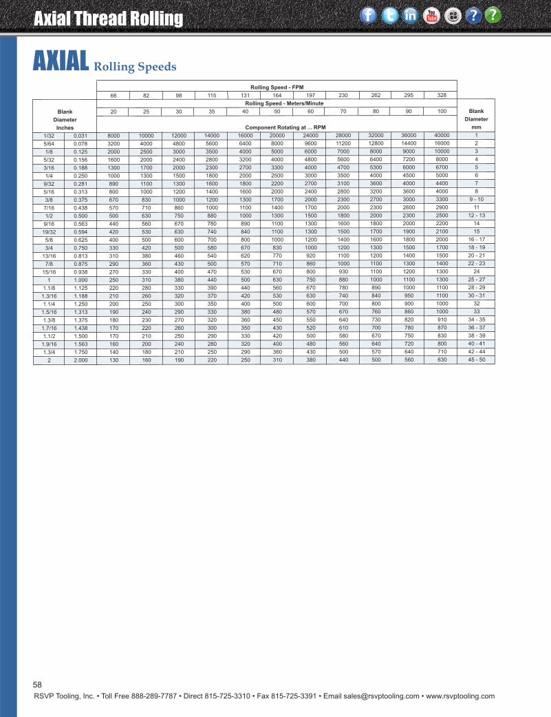
Axial Thread Rolling
RSVP Tooling, Inc. • Toll Free 888-289-7787 • Direct 815-725-3310 • Fax 815-725-3391 • Email [email protected] • www.rsvptooling.com
58
AXIAL Rolling SpeedsRolling Speed - FPM
66 82 98 115 131 164 197 230 262 295 328
Rolling Speed - Meters/Minute
Blank 20 25 30 35 40 50 60 70 80 90 100 Blank
Diameter Diameter
Inches Component Rotating at ... RPM mm
1/32 0.031 8000 10000 12000 14000 16000 20000 24000 28000 32000 36000 40000 1
5/64 0.078 3200 4000 4800 5600 6400 8000 9600 11200 12800 14400 16000 2
1/8 0.125 2000 2500 3000 3500 4000 5000 6000 7000 8000 9000 10000 3
5/32 0.156 1600 2000 2400 2800 3200 4000 4800 5600 6400 7200 8000 4
3/16 0.188 1300 1700 2000 2300 2700 3300 4000 4700 5300 6000 6700 5
1/4 0.250 1000 1300 1500 1800 2000 2500 3000 3500 4000 4500 5000 6
9/32 0.281 890 1100 1300 1600 1800 2200 2700 3100 3600 4000 4400 7
5/16 0.313 800 1000 1200 1400 1600 2000 2400 2800 3200 3600 4000 8
3/8 0.375 670 830 1000 1200 1300 1700 2000 2300 2700 3000 3300 9 - 10
7/16 0.438 570 710 860 1000 1100 1400 1700 2000 2300 2600 2900 11
1/2 0.500 500 630 750 880 1000 1300 1500 1800 2000 2300 2500 12 - 13
9/16 0.563 440 560 670 780 890 1100 1300 1600 1800 2000 2200 14
19/32 0.594 420 530 630 740 840 1100 1300 1500 1700 1900 2100 15
5/8 0.625 400 500 600 700 800 1000 1200 1400 1600 1800 2000 16 - 17
3/4 0.750 330 420 500 580 670 830 1000 1200 1300 1500 1700 18 - 19
13/16 0.813 310 380 460 540 620 770 920 1100 1200 1400 1500 20 - 21
7/8 0.875 290 360 430 500 570 710 860 1000 1100 1300 1400 22 - 23
15/16 0.938 270 330 400 470 530 670 800 930 1100 1200 1300 24
1 1.000 250 310 380 440 500 630 750 880 1000 1100 1300 25 - 27
1.1/8 1.125 220 280 330 390 440 560 670 780 890 1000 1100 28 - 29
1.3/16 1.188 210 260 320 370 420 530 630 740 840 950 1100 30 - 31
1.1/4 1.250 200 250 300 350 400 500 600 700 800 900 1000 32
1.5/16 1.313 190 240 290 330 380 480 570 670 760 860 1000 33
1.3/8 1.375 180 230 270 320 360 450 550 640 730 820 910 34 - 35
1.7/16 1.438 170 220 260 300 350 430 520 610 700 780 870 36 - 37
1.1/2 1.500 170 210 250 290 330 420 500 580 670 750 830 38 - 39
1.9/16 1.563 160 200 240 280 320 400 480 560 640 720 800 40 - 41
1.3/4 1.750 140 180 210 250 290 360 430 500 570 640 710 42 - 44
2 2.000 130 160 190 220 250 310 380 440 500 560 630 45 - 50
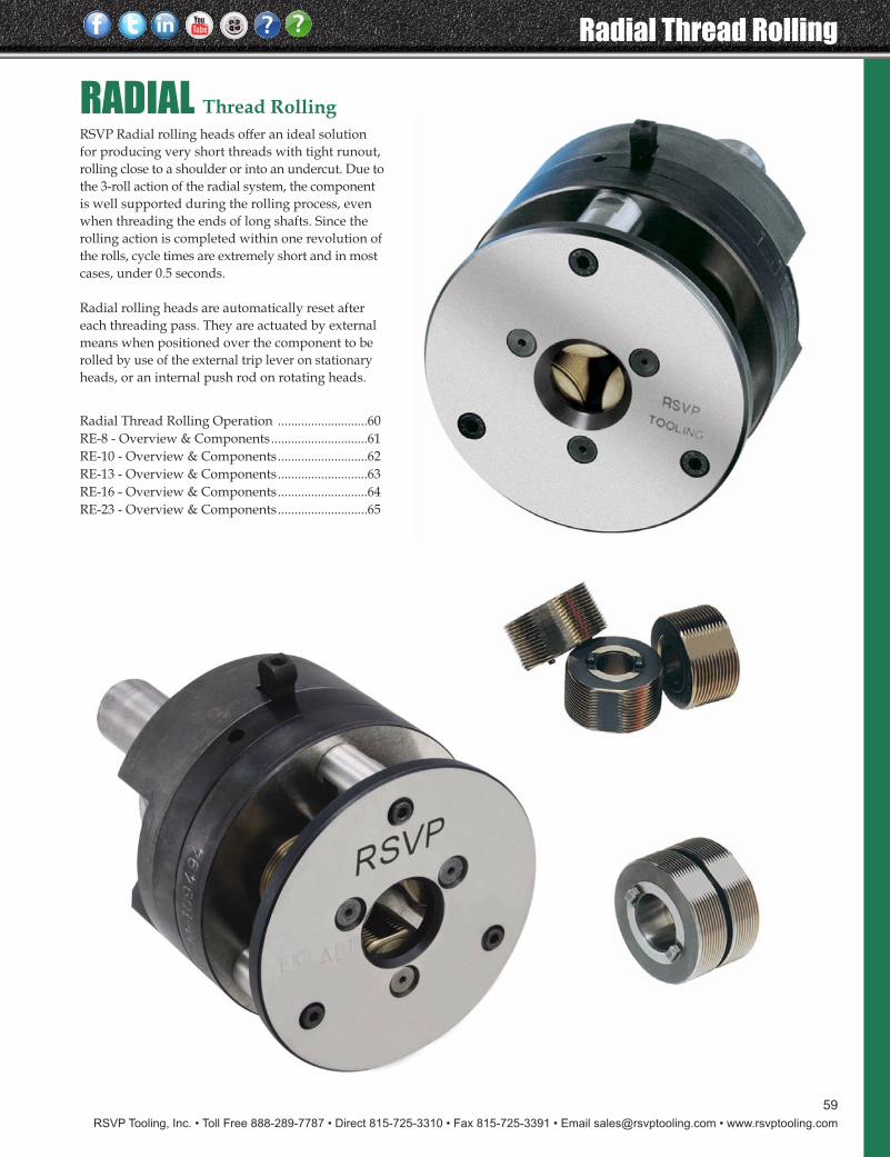
RSVP Tooling, Inc. • Toll Free 888-289-7787 • Direct 815-725-3310 • Fax 815-725-3391 • Email [email protected] • www.rsvptooling.com
59
Radial Thread Rolling
RSVP Radial rolling heads offer an ideal solutionfor producing very short threads with tight runout,rolling close to a shoulder or into an undercut. Due tothe 3-roll action of the radial system, the componentis well supported during the rolling process, evenwhen threading the ends of long shafts. Since therolling action is completed within one revolution ofthe rolls, cycle times are extremely short and in mostcases, under 0.5 seconds.
Radial rolling heads are automatically reset aftereach threading pass. They are actuated by externalmeans when positioned over the component to berolled by use of the external trip lever on stationaryheads, or an internal push rod on rotating heads.
RADIAL Thread Rolling
Radial Thread Rolling Operation ...........................60RE-8 - Overview & Components.............................61RE-10 - Overview & Components...........................62RE-13 - Overview & Components...........................63RE-16 - Overview & Components...........................64RE-23 - Overview & Components...........................65
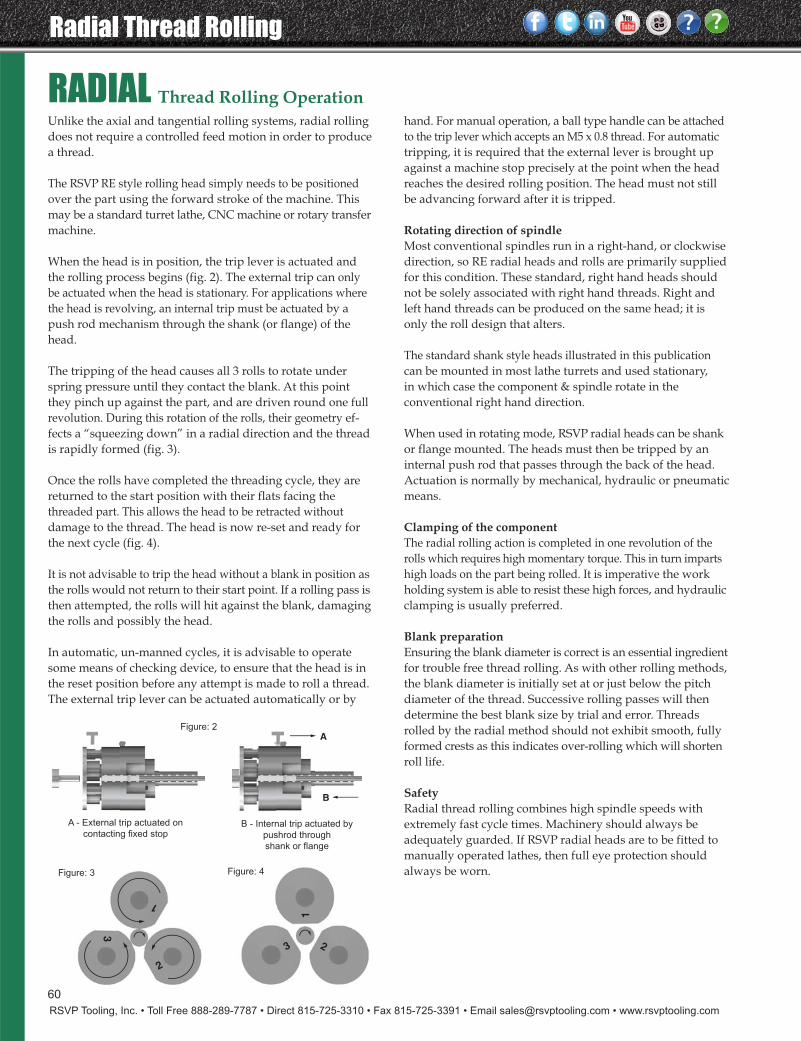
Radial Thread Rolling
RSVP Tooling, Inc. • Toll Free 888-289-7787 • Direct 815-725-3310 • Fax 815-725-3391 • Email [email protected] • www.rsvptooling.com
RADIAL Thread Rolling OperationUnlike the axial and tangential rolling systems, radial rollingdoes not require a controlled feed motion in order to producea thread.
The RSVP RE style rolling head simply needs to be positionedover the part using the forward stroke of the machine. Thismay be a standard turret lathe, CNC machine or rotary transfermachine.
When the head is in position, the trip lever is actuated andthe rolling process begins (fig. 2). The external trip can onlybe actuated when the head is stationary. For applications wherethe head is revolving, an internal trip must be actuated by apush rod mechanism through the shank (or flange) of thehead.
The tripping of the head causes all 3 rolls to rotate underspring pressure until they contact the blank. At this pointthey pinch up against the part, and are driven round one fullrevolution. During this rotation of the rolls, their geometry ef-fects a “squeezing down” in a radial direction and the threadis rapidly formed (fig. 3).
Once the rolls have completed the threading cycle, they arereturned to the start position with their flats facing thethreaded part. This allows the head to be retracted withoutdamage to the thread. The head is now re-set and ready forthe next cycle (fig. 4).
It is not advisable to trip the head without a blank in position asthe rolls would not return to their start point. If a rolling pass isthen attempted, the rolls will hit against the blank, damagingthe rolls and possibly the head.
In automatic, un-manned cycles, it is advisable to operatesome means of checking device, to ensure that the head is inthe reset position before any attempt is made to roll a thread.The external trip lever can be actuated automatically or by
hand. For manual operation, a ball type handle can be attachedto the trip lever which accepts an M5 x 0.8 thread. For automatictripping, it is required that the external lever is brought upagainst a machine stop precisely at the point when the headreaches the desired rolling position. The head must not stillbe advancing forward after it is tripped.
Rotating direction of spindleMost conventional spindles run in a right-hand, or clockwisedirection, so RE radial heads and rolls are primarily suppliedfor this condition. These standard, right hand heads shouldnot be solely associated with right hand threads. Right andleft hand threads can be produced on the same head; it isonly the roll design that alters.
The standard shank style heads illustrated in this publicationcan be mounted in most lathe turrets and used stationary,in which case the component & spindle rotate in theconventional right hand direction.
When used in rotating mode, RSVP radial heads can be shankor flange mounted. The heads must then be tripped by aninternal push rod that passes through the back of the head.Actuation is normally by mechanical, hydraulic or pneumaticmeans.
Clamping of the componentThe radial rolling action is completed in one revolution of therolls which requires high momentary torque. This in turn impartshigh loads on the part being rolled. It is imperative the workholding system is able to resist these high forces, and hydraulicclamping is usually preferred.
Blank preparationEnsuring the blank diameter is correct is an essential ingredientfor trouble free thread rolling. As with other rolling methods,the blank diameter is initially set at or just below the pitchdiameter of the thread. Successive rolling passes will thendetermine the best blank size by trial and error. Threadsrolled by the radial method should not exhibit smooth, fullyformed crests as this indicates over-rolling which will shortenroll life.
SafetyRadial thread rolling combines high spindle speeds withextremely fast cycle times. Machinery should always beadequately guarded. If RSVP radial heads are to be fitted tomanually operated lathes, then full eye protection shouldalways be worn.
B - Internal trip actuated by
pushrod through
shank or flange
A - External trip actuated on
contacting fixed stop
B
A
1
2
3
1
23
Figure: 3
Figure: 2
Figure: 4
60
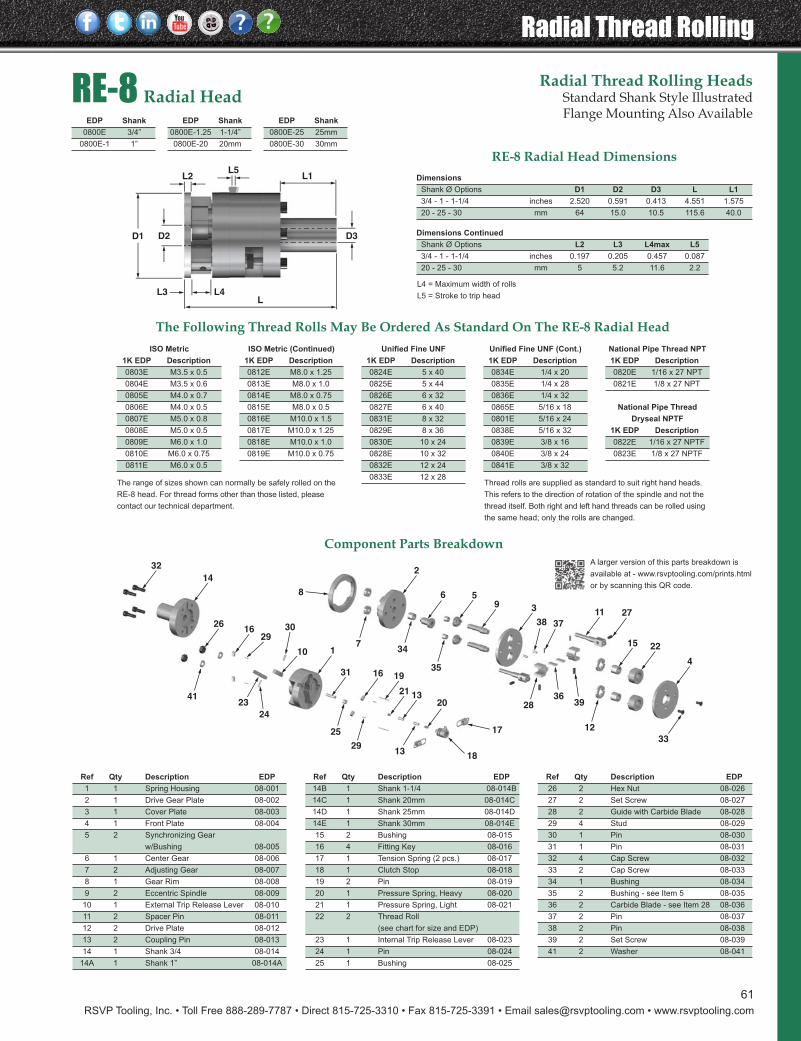
RSVP Tooling, Inc. • Toll Free 888-289-7787 • Direct 815-725-3310 • Fax 815-725-3391 • Email [email protected] • www.rsvptooling.com
61
Radial Thread Rolling
D1 D3D2
L1L5
LL4L3
L2
33
4
2215
2711395
2
6
7
32
14
2616
2930
110
31 16
21
19
2013
13
17
8
3738
2836
12
35
2341
34
25
29
24
18
39
RE-8 Radial HeadRadial Thread Rolling Heads
Standard Shank Style IllustratedFlange Mounting Also Available
Ref Qty Description EDP
26 2 Hex Nut 08-026
27 2 Set Screw 08-027
28 2 Guide with Carbide Blade 08-028
29 4 Stud 08-029
30 1 Pin 08-030
31 1 Pin 08-031
32 4 Cap Screw 08-032
33 2 Cap Screw 08-033
34 1 Bushing 08-034
35 2 Bushing - see Item 5 08-035
36 2 Carbide Blade - see Item 28 08-036
37 2 Pin 08-037
38 2 Pin 08-038
39 2 Set Screw 08-039
41 2 Washer 08-041
Ref Qty Description EDP
1 1 Spring Housing 08-001
2 1 Drive Gear Plate 08-002
3 1 Cover Plate 08-003
4 1 Front Plate 08-004
5 2 Synchronizing Gear
w/Bushing 08-005
6 1 Center Gear 08-006
7 2 Adjusting Gear 08-007
8 1 Gear Rim 08-008
9 2 Eccentric Spindle 08-009
10 1 External Trip Release Lever 08-010
11 2 Spacer Pin 08-011
12 2 Drive Plate 08-012
13 2 Coupling Pin 08-013
14 1 Shank 3/4 08-014
14A 1 Shank 1” 08-014A
Ref Qty Description EDP
14B 1 Shank 1-1/4 08-014B
14C 1 Shank 20mm 08-014C
14D 1 Shank 25mm 08-014D
14E 1 Shank 30mm 08-014E
15 2 Bushing 08-015
16 4 Fitting Key 08-016
17 1 Tension Spring (2 pcs.) 08-017
18 1 Clutch Stop 08-018
19 2 Pin 08-019
20 1 Pressure Spring, Heavy 08-020
21 1 Pressure Spring, Light 08-021
22 2 Thread Roll
(see chart for size and EDP)
23 1 Internal Trip Release Lever 08-023
24 1 Pin 08-024
25 1 Bushing 08-025
The Following Thread Rolls May Be Ordered As Standard On The RE-8 Radial HeadNational Pipe Thread NPT
1K EDP Description
0820E 1/16 x 27 NPT
0821E 1/8 x 27 NPT
National Pipe Thread
Dryseal NPTF
1K EDP Description
0822E 1/16 x 27 NPTF
0823E 1/8 x 27 NPTF
Unified Fine UNF (Cont.)
1K EDP Description
0834E 1/4 x 20
0835E 1/4 x 28
0836E 1/4 x 32
0865E 5/16 x 18
0801E 5/16 x 24
0838E 5/16 x 32
0839E 3/8 x 16
0840E 3/8 x 24
0841E 3/8 x 32
Unified Fine UNF
1K EDP Description
0824E 5 x 40
0825E 5 x 44
0826E 6 x 32
0827E 6 x 40
0831E 8 x 32
0829E 8 x 36
0830E 10 x 24
0828E 10 x 32
0832E 12 x 24
0833E 12 x 28
ISO Metric (Continued)
1K EDP Description
0812E M8.0 x 1.25
0813E M8.0 x 1.0
0814E M8.0 x 0.75
0815E M8.0 x 0.5
0816E M10.0 x 1.5
0817E M10.0 x 1.25
0818E M10.0 x 1.0
0819E M10.0 x 0.75
ISO Metric
1K EDP Description
0803E M3.5 x 0.5
0804E M3.5 x 0.6
0805E M4.0 x 0.7
0806E M4.0 x 0.5
0807E M5.0 x 0.8
0808E M5.0 x 0.5
0809E M6.0 x 1.0
0810E M6.0 x 0.75
0811E M6.0 x 0.5
EDP Shank
0800E 3/4”
0800E-1 1”
EDP Shank
0800E-1.25 1-1/4”
0800E-20 20mm
Component Parts Breakdown
Thread rolls are supplied as standard to suit right hand heads.
This refers to the direction of rotation of the spindle and not the
thread itself. Both right and left hand threads can be rolled using
the same head; only the rolls are changed.
The range of sizes shown can normally be safely rolled on the
RE-8 head. For thread forms other than those listed, please
contact our technical department.
RE-8 Radial Head DimensionsDimensions
Shank Ø Options D1 D2 D3 L L1
3/4 - 1 - 1-1/4 inches 2.520 0.591 0.413 4.551 1.575
20 - 25 - 30 mm 64 15.0 10.5 115.6 40.0
Dimensions Continued
Shank Ø Options L2 L3 L4max L5
3/4 - 1 - 1-1/4 inches 0.197 0.205 0.457 0.087
20 - 25 - 30 mm 5 5.2 11.6 2.2
L4 = Maximum width of rolls
L5 = Stroke to trip head
EDP Shank
0800E-25 25mm
0800E-30 30mm
A larger version of this parts breakdown is
available at - www.rsvptooling.com/prints.html
or by scanning this QR code.
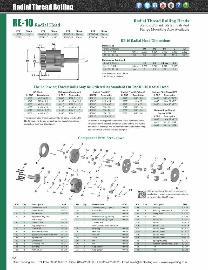
Radial Thread Rolling
RSVP Tooling, Inc. • Toll Free 888-289-7787 • Direct 815-725-3310 • Fax 815-725-3391 • Email [email protected] • www.rsvptooling.com
D1 D3D2
L1L5
LL4L3
L2
33
415
2212
116
3938
35 5
28 7 2
34
32
43
41
48
26
13
44 17
1816
10
3013
21
42
27
37
16
19
29
2925 20
8
Component Parts Breakdown
RE-10 Radial HeadRadial Thread Rolling Heads
Standard Shank Style IllustratedFlange Mounting Also Available
The Following Thread Rolls May Be Ordered As Standard On The RE-10 Radial Head
RE-10 Radial Head DimensionsDimensions
Shank Ø Options D1 D2 D3 L L1
3/4 - 1 - 1-1/4 inches 3.937 1.024 0.492 6.480 2.362
20 - 25 - 30 - 32 mm 100 26.0 12.5 164.6 60.0
Dimensions Continued
Shank Ø Options L2 L3 L4max L5
3/4 - 1 - 1-1/4 inches 0.236 0.244 0.772 0.138
20 - 25 - 30 - 32 mm 6 6.2 20 3.5
L4 = Maximum width of rolls
L5 = Stroke to trip head
Ref Qty Description EDP
34 1 Bushing 10-034
35 3 Bushing - see Item 5 10-035
37 3 Fitting Key 10-037
38 3 Pin 10-038
41 1 Shank 3/4 10-041
41A 1 Shank 1” 10-041A
41B 1 Shank 1-1/4 10-041B
41C 1 Shank 20mm 10-041C
41D 1 Shank 25mm 10-041D
41E 1 Shank 30mm 10-041E
41F 1 Shank 32mm 10-041F
42 1 Spring Housing 10-042
43 1 Internal Trip Release Lever 10-043
44 1 Pin 10-044
48 1 Pin 10-048
Ref Qty Description EDP
2 1 Drive Gear Plate 10-002
3 1 Cover Plate 10-003
4 1 Front Plate 10-004
5 3 Synchronizing Gear
w/Bushing 10-005
6 1 Center Gear 10-006
7 3 Adjusting Gear 10-007
8 1 Gear Rim 10-008
9 3 Eccentric Spindle 10-009
10 1 External Trip Release Lever 10-010
11 3 Spacer Pin 10-011
12 3 Drive Plate 10-012
13 2 Coupling Pin 10-013
15 3 Bushing 10-015
16 4 Fitting Key 10-016
Ref Qty Description EDP
17 1 Tension Spring (3 pcs.) 10-017
18 1 Clutch Stop 10-018
19 3 Pin 10-019
20 1 Pressure Spring, Heavy 10-020
21 1 Pressure Spring, Light 10-021
22 3 Thread Roll
(see chart for size and EDP)
25 1 Bushing 10-025
26 2 Hex Nut 10-026
27 2 Washer 10-027
28 2 Stud 10-028
29 4 Pin 10-029
30 1 Pin 10-030
32 6 Cap Screw 10-032
33 3 Cap Screw 10-033
National Pipe Thread NPT
1K EDP Description
1043E 1/16 x 27 NPT
1044E 1/8 x 27 NPT
1045E 1/4 x 18 NPT
National Pipe Thread
Dryseal NPTF
1K EDP Description
1046E 1/16 x 27 NPTF
1047E 1/8 x 27 NPTF
1048E 1/4 x 18 NPTF
Unified Fine UNF (Cont.)
1K EDP Description
1027E 7/16 x 28
1028E 1/2 x 20
1029E 1/2 x 28
1002E 9/16 x 18
1030E 9/16 x 20
1031E 9/16 x 24
Unified Fine UNF
1K EDP Description
1021E 5/16 x 20
1022E 5/16 x 24
1023E 5/16 x 32
1024E 3/8 x 16
1025E 3/8 x 24
1026E 3/8 x 32
1001E 7/16 x 20
ISO Metric (Continued)
1K EDP Description
1009E M12.0 x 1.0
1010E M12.0 x 1.25
1011E M12.0 x 1.5
1012E M14.0 x 1.25
1013E M14.0 x 1.5
1014E M14.0 x 1.0
ISO Metric
1K EDP Description
1003E M8.0 x 0.75
1004E M8.0 x 1.0
1005E M8.0 x 1.25
1006E M10.0 x 1.0
1007E M10.0 x 1.25
1008E M10.0 x 1.5
EDP Shank
1000E 3/4”
1000E-1 1”
EDP Shank
1000E-1.25 1-1/4”
1000E-1.5 1-1/2”
Thread rolls are supplied as standard to suit right hand heads.
This refers to the direction of rotation of the spindle and not the
thread itself. Both right and left hand threads can be rolled using
the same head; only the rolls are changed.
The range of sizes shown can normally be safely rolled on the
RE-10 head. For thread forms other than those listed, please
contact our technical department.
EDP Shank
1000E-20 20mm
1000E-25 25mm
EDP Shank
1000E-30 30mm
1000E-32 32mm
A larger version of this parts breakdown is
available at - www.rsvptooling.com/prints.html
or by scanning this QR code.
62
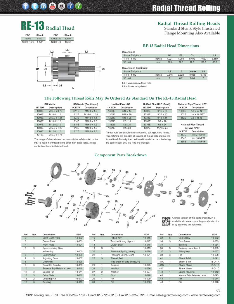
RSVP Tooling, Inc. • Toll Free 888-289-7787 • Direct 815-725-3310 • Fax 815-725-3391 • Email [email protected] • www.rsvptooling.com
Radial Thread RollingRadial Thread Rolling Heads
Standard Shank Style IllustratedFlange Mounting Also Available
RE-13 Radial Head DimensionsDimensions
Shank Ø Options D1 D2 D3 L L1
1-1/4 - 1-1/2 inches 4.921 1.260 0.492 7.622 3.150
30 - 40 mm 125 32.0 12.5 193.6 80.0
Dimensions Continued
Shank Ø Options L2 L3 L4max L5
1-1/4 - 1-1/2 inches 0.315 0.323 0.968 0.118
30 - 40 mm 8 8.2 24.6 3
L4 = Maximum width of rolls
L5 = Stroke to trip head
Component Parts Breakdown
RE-13 Radial Head
The Following Thread Rolls May Be Ordered As Standard On The RE-13 Radial Head
Ref Qty Description EDP
32 6 Cap Screw 10-032
33 3 Cap Screw 13-033
34 1 Bushing 13-034
35 3 Bushing - see Item 5 13-035
37 3 Fitting Key 13-037
38 3 Pin 13-038
41 1 Shank 1-1/2 13-041
41A 1 Shank 1-1/4 13-041A
41B 1 Shank 30mm 13-041B
41C 1 Shank 40mm 13-041C
42 1 Spring Housing 13-042
43 1 Internal Trip Release Lever 13-043
44 1 Pin 10-044
48 1 Pin 13-048
Ref Qty Description EDP
2 1 Drive Gear Plate 13-002
3 1 Cover Plate 13-003
4 1 Front Plate 13-004
5 3 Synchronizing Gear
w/Bushing 13-005
6 1 Center Gear 13-006
7 3 Adjusting Gear 13-007
8 1 Gear Rim 13-008
9 3 Eccentric Spindle 13-009
10 1 External Trip Release Lever 13-010
11 3 Spacer Pin 13-011
12 3 Drive Plate 13-012
13 2 Coupling Pin 10-013
15 3 Bushing 13-015
Ref Qty Description EDP
16 4 Fitting Key 10-016
17 1 Tension Spring (3 pcs.) 13-017
18 1 Clutch Stop 13-018
19 3 Pin 10-019
20 1 Pressure Spring, Heavy 13-020
21 1 Pressure Spring, Light 13-021
22 3 Thread Roll
(see chart for size and EDP)
25 1 Bushing 10-025
26 2 Hex Nut 10-026
27 2 Washer 13-027
28 2 Stud 13-028
29 4 Pin 10-029
30 1 Pin 10-030
National Pipe Thread NPT
1K EDP Description
1350E 1/8 x 27 NPT
1302E 1/4 x 18 NPT
1352E 3/8 x 18 NPT
National Pipe Thread
Dryseal NPTF
1K EDP Description
1353E 1/8 x 27 NPTF
1354E 1/4 x 18 NPTF
1355E 3/8 x 18 NPTF
Unified Fine UNF (Cont.)
1K EDP Description
1332E 9/16 x 18
1333E 9/16 x 20
1334E 9/16 x 24
1335E 5/8 x 18
1336E 5/8 x 24
1337E 11/16 x 24
Unified Fine UNF
1K EDP Description
1326E 7/16 x 14
1301E 7/16 x 20
1328E 7/16 x 28
1329E 1/2 x 13
1330E 1/2 x 20
1331E 1/2 x 28
ISO Metric (Continued)
1K EDP Description
1311E M14.0 x 1.0
1312E M14.0 x 1.25
1323E M14.0 x 1.5
1314E M16.0 x 1.0
1315E M16.0 x 1.5
1316E M18.0 x 1.0
1317E M18.0 x 1.5
ISO Metric
1K EDP Description
1303E M10.0 x 0.75
1304E M10.0 x 1.0
1305E M10.0 x 1.25
1306E M10.0 x 1.5
1307E M12.0 x 1.0
1308E M12.0 x 1.25
1309E M12.0 x 1.5
1310E M12.0 x 1.75
EDP Shank
1300E 1-1/2”
1300E-1.25 1-1/4”
EDP Shank
1300E-30 30mm
1300E-40 40mm
Thread rolls are supplied as standard to suit right hand heads.
This refers to the direction of rotation of the spindle and not the
thread itself. Both right and left hand threads can be rolled using
the same head; only the rolls are changed.
The range of sizes shown can normally be safely rolled on the
RE-13 head. For thread forms other than those listed, please
contact our technical department.
D1 D3D2
L1L5
LL4L3
L2
33
415
2212
116
3938
35 5
28 7 2
34
32
43
41
48
26
13
44 17
1816
10
3013
21
42
27
37
16
19
29
2925 20
8
A larger version of this parts breakdown is
available at - www.rsvptooling.com/prints.html
or by scanning this QR code.
63
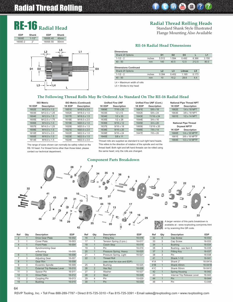
Radial Thread Rolling
RSVP Tooling, Inc. • Toll Free 888-289-7787 • Direct 815-725-3310 • Fax 815-725-3391 • Email [email protected] • www.rsvptooling.com
Radial Thread Rolling HeadsStandard Shank Style IllustratedFlange Mounting Also Available
RE-16 Radial Head DimensionsDimensions
Shank Ø Options D1 D2 D3 L L1
1-1/2 - 2 inches 5.512 1.594 0.492 8.366 3.150
40 - 50 mm 140 40.5 12.5 212.5 80.0
Dimensions Continued
Shank Ø Options L2 L3 L4max L5
1-1/2 - 2 inches 0.394 0.402 1.165 0.173
40 - 50 mm 10 10.2 29.6 4.4
L4 = Maximum width of rolls
L5 = Stroke to trip head
Component Parts Breakdown
RE-16 Radial Head
The Following Thread Rolls May Be Ordered As Standard On The RE-16 Radial Head
Ref Qty Description EDP
32 6 Cap Screw 16-032
33 3 Cap Screw 16-033
34 1 Bushing 16-034
35 3 Bushing - see Item 5 16-035
37 3 Fitting Key 16-037
38 3 Pin 16-038
41 1 Shank 1-1/2 16-041
41A 1 Shank 2” 16-041A
41B 1 Shank 40mm 16-041B
41C 1 Shank 50mm 16-041C
42 1 Spring Housing 16-042
43 1 Internal Trip Release Lever 16-043
44 1 Pin 16-044
48 1 Pin 13-048
Ref Qty Description EDP
2 1 Drive Gear Plate 16-002
3 1 Cover Plate 16-003
4 1 Front Plate 16-004
5 3 Synchronizing Gear
w/Bushing 16-005
6 1 Center Gear 16-006
7 3 Adjusting Gear 16-007
8 1 Gear Rim 16-008
9 3 Eccentric Spindle 16-009
10 1 External Trip Release Lever 16-010
11 3 Spacer Pin 16-011
12 3 Drive Plate 16-012
13 2 Coupling Pin 16-013
15 3 Bushing 16-015
Ref Qty Description EDP
16 4 Fitting Key 16-016
17 1 Tension Spring (3 pcs.) 16-017
18 1 Clutch Stop 16-018
19 3 Pin 16-019
20 1 Pressure Spring, Heavy 16-020
21 1 Pressure Spring, Light 16-021
22 3 Thread Roll
(see chart for size and EDP)
25 1 Bushing 16-025
26 2 Hex Nut 16-026
27 2 Washer 16-027
28 2 Stud 16-028
29 4 Pin 10-029
30 1 Pin 16-030
National Pipe Thread NPT
1K EDP Description
1662E 1/4 x 18 NPT
1663E 3/8 x 18 NPT
1601E 1/2 x 14 NPT
National Pipe Thread
Dryseal NPTF
1K EDP Description
1660E 1/4 x 18 NPTF
1661E 3/8 x 18 NPTF
1664E 1/2 x 14 NPTF
Unified Fine UNF (Cont.)
1K EDP Description
1641E 5/8 x 18
1642E 5/8 x 24
1643E 11/16 x 24
1644E 3/4 x 16
1645E 3/4 x 20
1665E 13/16 x 20
1646E 7/8 x 14
1647E 7/8 x 20
Unified Fine UNF
1K EDP Description
1669E 7/16 x 20
1633E 1/2 x13
1634E 1/2 x 20
1635E 1/2 x 28
1636E 9/16 x 12
1637E 9/16 x 18
1638E 9/16 x 20
1639E 9/16 x 24
1640E 5/8 x 11
ISO Metric (Continued)
1K EDP Description
1651E M16.0 x 2.0
1652E M18.0 x 1.0
1617E M18.0 x 1.5
1618E M18.0 x 2.0
1619E M20.0 x 1.0
1620E M20.0 x 1.5
1621E M20.0 x 2.0
1622E M22.0 x 1.0
1623E M22.0 x 1.5
1624E M22.0 x 2.0
ISO Metric
1K EDP Description
1602E M12.0 x 1.0
1603E M12.0 x 1.25
1604E M12.0 x 1.5
1605E M12.0 x 1.75
1606E M14.0 x 1.0
1607E M14.0 x 1.25
1608E M14.0 x 1.5
1610E M14.0 x 2.0
1650E M16.0 x 1.0
1614E M16.0 x 1.5
EDP Shank
1600E 1-1/2”
1600E-2 2”
EDP Shank
1600E-40 40mm
1600E-50 50mm
Thread rolls are supplied as standard to suit right hand heads.
This refers to the direction of rotation of the spindle and not the
thread itself. Both right and left hand threads can be rolled using
the same head; only the rolls are changed.
The range of sizes shown can normally be safely rolled on the
RE-16 head. For thread forms other than those listed, please
contact our technical department.
D1 D3D2
L1L5
LL4L3
L2
33
415
2212
116
3938
35 5
28 7 2
34
32
43
41
48
26
13
44 17
1816
10
3013
21
42
27
37
16
19
29
2925 20
8
A larger version of this parts breakdown is
available at - www.rsvptooling.com/prints.html
or by scanning this QR code.
64
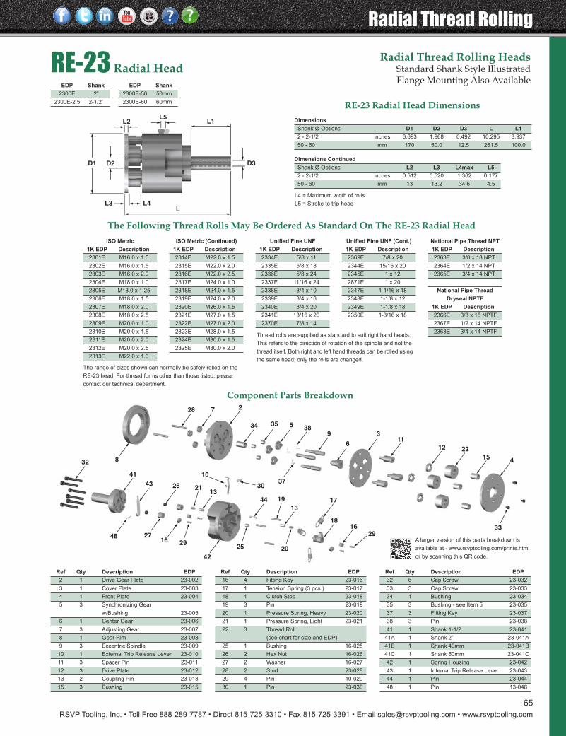
RSVP Tooling, Inc. • Toll Free 888-289-7787 • Direct 815-725-3310 • Fax 815-725-3391 • Email [email protected] • www.rsvptooling.com
Radial Thread Rolling
33
415
2212
116
3938
35 5
28 7 2
34
32
43
41
48
26
13
44 17
1816
10
3013
21
42
27
37
16
19
29
2925 20
8
Radial Thread Rolling HeadsStandard Shank Style IllustratedFlange Mounting Also Available
RE-23 Radial Head DimensionsDimensions
Shank Ø Options D1 D2 D3 L L1
2 - 2-1/2 inches 6.693 1.968 0.492 10.295 3.937
50 - 60 mm 170 50.0 12.5 261.5 100.0
Dimensions Continued
Shank Ø Options L2 L3 L4max L5
2 - 2-1/2 inches 0.512 0.520 1.362 0.177
50 - 60 mm 13 13.2 34.6 4.5
L4 = Maximum width of rolls
L5 = Stroke to trip head
Component Parts Breakdown
RE-23 Radial Head
The Following Thread Rolls May Be Ordered As Standard On The RE-23 Radial Head
Ref Qty Description EDP
32 6 Cap Screw 23-032
33 3 Cap Screw 23-033
34 1 Bushing 23-034
35 3 Bushing - see Item 5 23-035
37 3 Fitting Key 23-037
38 3 Pin 23-038
41 1 Shank 1-1/2 23-041
41A 1 Shank 2” 23-041A
41B 1 Shank 40mm 23-041B
41C 1 Shank 50mm 23-041C
42 1 Spring Housing 23-042
43 1 Internal Trip Release Lever 23-043
44 1 Pin 23-044
48 1 Pin 13-048
Ref Qty Description EDP
2 1 Drive Gear Plate 23-002
3 1 Cover Plate 23-003
4 1 Front Plate 23-004
5 3 Synchronizing Gear
w/Bushing 23-005
6 1 Center Gear 23-006
7 3 Adjusting Gear 23-007
8 1 Gear Rim 23-008
9 3 Eccentric Spindle 23-009
10 1 External Trip Release Lever 23-010
11 3 Spacer Pin 23-011
12 3 Drive Plate 23-012
13 2 Coupling Pin 23-013
15 3 Bushing 23-015
Ref Qty Description EDP
16 4 Fitting Key 23-016
17 1 Tension Spring (3 pcs.) 23-017
18 1 Clutch Stop 23-018
19 3 Pin 23-019
20 1 Pressure Spring, Heavy 23-020
21 1 Pressure Spring, Light 23-021
22 3 Thread Roll
(see chart for size and EDP)
25 1 Bushing 16-025
26 2 Hex Nut 16-026
27 2 Washer 16-027
28 2 Stud 23-028
29 4 Pin 10-029
30 1 Pin 23-030
National Pipe Thread NPT
1K EDP Description
2363E 3/8 x 18 NPT
2364E 1/2 x 14 NPT
2365E 3/4 x 14 NPT
National Pipe Thread
Dryseal NPTF
1K EDP Description
2366E 3/8 x 18 NPTF
2367E 1/2 x 14 NPTF
2368E 3/4 x 14 NPTF
Unified Fine UNF (Cont.)
1K EDP Description
2369E 7/8 x 20
2344E 15/16 x 20
2345E 1 x 12
2871E 1 x 20
2347E 1-1/16 x 18
2348E 1-1/8 x 12
2349E 1-1/8 x 18
2350E 1-3/16 x 18
Unified Fine UNF
1K EDP Description
2334E 5/8 x 11
2335E 5/8 x 18
2336E 5/8 x 24
2337E 11/16 x 24
2338E 3/4 x 10
2339E 3/4 x 16
2340E 3/4 x 20
2341E 13/16 x 20
2370E 7/8 x 14
ISO Metric (Continued)
1K EDP Description
2314E M22.0 x 1.5
2315E M22.0 x 2.0
2316E M22.0 x 2.5
2317E M24.0 x 1.0
2318E M24.0 x 1.5
2319E M24.0 x 2.0
2320E M26.0 x 1.5
2321E M27.0 x 1.5
2322E M27.0 x 2.0
2323E M28.0 x 1.5
2324E M30.0 x 1.5
2325E M30.0 x 2.0
ISO Metric
1K EDP Description
2301E M16.0 x 1.0
2302E M16.0 x 1.5
2303E M16.0 x 2.0
2304E M18.0 x 1.0
2305E M18.0 x 1.25
2306E M18.0 x 1.5
2307E M18.0 x 2.0
2308E M18.0 x 2.5
2309E M20.0 x 1.0
2310E M20.0 x 1.5
2311E M20.0 x 2.0
2312E M20.0 x 2.5
2313E M22.0 x 1.0
EDP Shank
2300E 2”
2300E-2.5 2-1/2”
EDP Shank
2300E-50 50mm
2300E-60 60mm
Thread rolls are supplied as standard to suit right hand heads.
This refers to the direction of rotation of the spindle and not the
thread itself. Both right and left hand threads can be rolled using
the same head; only the rolls are changed.
The range of sizes shown can normally be safely rolled on the
RE-23 head. For thread forms other than those listed, please
contact our technical department.
D1 D3D2
L1L5
LL4L3
L2
A larger version of this parts breakdown is
available at - www.rsvptooling.com/prints.html
or by scanning this QR code.
65

Tangential Thread Rolling
RSVP Tooling, Inc. • Toll Free 888-289-7787 • Direct 815-725-3310 • Fax 815-725-3391 • Email [email protected] • www.rsvptooling.com
TANGENTIAL Thread Rolling SystemOur RT Tangential system is interchangeable with the Fettestyle tangential thread rolling system. They will fit into yourexisting machine tool holders and take the same rolls you arecurrently using:
RT10 = T12 RT20 = T18 RT30 = T27
By using lathe type machine tools with automatic, power infeedas with controlled or hydraulic automatics, hydraulicallyoperated copy lathe, NC/CNC lathes, etc., it is now possibleto feed from the side of the part and obtain all of the advantagesof the rolling method. RSVP tangential type rolling attachmentsare especially suited to produce the following threads andprofiles:
• Thread rolled behind a shoulder
• Extremely short thread lengths
• Threads with a very short runout(approx. 1/2 - 1 x pitch)
• Tapered threads
• Straight knurls DIN 82
• Burnishing
• Forming
The component must rotate for this application. RSVP tangentialside rolling attachments are available in 3 sizes covering a widerange of diameters. It is recommended that the largest rollingattachment that can be adapted on the machine always beused, thereby offering the advantage that the entire workrange of the machine can be utilized. Longer threads,maximum component shoulder diameters, and a higherefficiency of the rolling attachment will be attained that way.
Attachments.................................................................................67Thread Rolls & Setting Gauges .................................................68 Design of Rolls ............................................................................69RT10 - Overview & Components..............................................70RT20 - Overview & Components..............................................71RT30 - Overview & Components..............................................72 Tangential Thread Roll Charts ..................................................73 Custome Tangential Thread Rolls ............................................74
66
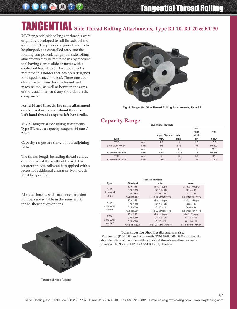
RSVP Tooling, Inc. • Toll Free 888-289-7787 • Direct 815-725-3310 • Fax 815-725-3391 • Email [email protected] • www.rsvptooling.com
67
Tangential Thread Rolling
TANGENTIAL Side Thread Rolling Attachments, Type RT 10, RT 20 & RT 30
Capacity RangeCylindrical Threads
max.
Pitch Roll
Major Diameter min. width
Type min. max. TPI max.1)
RT10 mm 1.6 14 1.5 15.5
up to work No. 66 inch 1/6 9/16 16 0.6102
RT20 mm 2 30 2 21.5
up to work No. 548 inch 5/64 1 3/16 12 0.8465
RT30 mm 2 42 2.5 31
up to work No. 467 inch 5/64 1 5/8 10 1.2205
RSVP tangential side rolling attachments wereoriginally developed to roll threads behinda shoulder. The process requires the rolls tobe plunged, at a controlled rate, into therotating component. Tangential side rollingattachments may be mounted in any machinetool having a cross slide or turret with acontrolled feed stroke. The attachment ismounted in a holder that has been designedfor a specific machine tool. There must beclearance between the attachment andmachine tool, as well as between the armsof the attachment and any shoulder on thecomponent.
For left-hand threads, the same attachmentcan be used as for right-hand threads.Left-hand threads require left-hand rolls.
RSVP - Tangential side rolling attachments,Type RT, have a capacity range to 64 mm /2.52".
Capacity ranges are shown in the adjoiningtable.
The thread length including thread runoutcan not exceed the width of the roll. Forshorter threads, rolls can be supplied with arecess for additional clearance. Roll widthmust be specified.
Fig. 1: Tangential Side Thread Rolling Attachments, Type RT
Also attachments with smaller constructionnumbers are suitable in the same workrange, there are exceptions.
Tapered Threads
Type Standard min. max.
DIN 158 M 6 x 1 taper M 14 x 1.5 taper
DIN 2999 G 1/16 - 28 G 1/4 - 19
DIN 3858 G 1/8 - 28 G 1/4 - 19
ANSIB1.20.1 1/16-27NPT(NPTF) 1/4-18NPT(NPTF)
DIN 158 M 6 x 1 taper M 30 x 1.5 taper
DIN 2999 G 1/16 - 28 G 3/4 - 14
DIN 3858 G 1/8 - 28 G 3/4 - 14
ANSIB1.20.1 1/16-27NPT(NPTF) 1/2-14NPT(NPTF)
DIN 158 M 6 x 1 taper M 42 x 2 taper
DIN 2999 G 1/16 - 28 G 1 1/4 - 11
DIN 3858 G 1/8 - 28 G 1 1/4 - 11
ANSI B 1.20.1 1/6 - 27 NPT (NPTF) 1 -11.5 NPT (NPTF)
RT10
Up to work
No 66
RT20
up to work
No 548
RT30
up to work
No. 467
Tolerances for Shoulder dia. and cam rise.With metric (DIN 458) and Whitworth (DIN 2999, DIN 3858) profiles theshoulder dia. and cam rise with cylindrical threads are dimensionallyidentical, NPT - and NPTF (ANSI B 1.20.1) threads.
Tangential Head Adapter
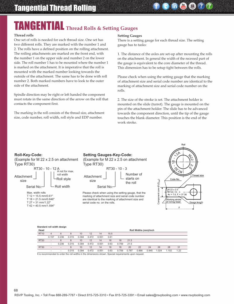
Tangential Thread Rolling
RSVP Tooling, Inc. • Toll Free 888-289-7787 • Direct 815-725-3310 • Fax 815-725-3391 • Email [email protected] • www.rsvptooling.com
TANGENTIAL Thread Rolls & Setting Gauges
Standard roll width design
Head Roll Widths (mm)/inch
RT10 4 6 8 10 12 14 15.5
0.157 0.236 0.315 0.394 0.472 0.551 0.61
RT20 - 6 8 10 12 14 16 18 21.5
- 0.236 0.315 0.394 0.472 0.551 0.63 0.709 21.5
RT30 - - 8 10 12 14 16 18 20 22 24 26 28 31
- - 0.315 0.394 0.472 0.551 0.63 0.709 0.787 0.866 0.945 1.024 1.102 1.22
It is recommended to order the roll widths in the dimensions shown. Special requirements upon request.
Thread rollsOne set of rolls is needed for each thread size. One set hastwo different rolls. They are marked with the number 1 and2. The rolls have a defined position on the rolling attachment.The roiling attachments are marked on the front end, withthe number 1 on the upper side and number 2 on the lowerside. The roll number 1 has to be mounted where the number 1is marked on the attachment. It is imperative that the roll ismounted with the marked number looking towards theoutside of the attachment. The same has to be done with rollnumber 2. Both marked numbers have to look to the outerside of the attachment.
Spindle direction may be right or left handed the componentmust rotate in the same direction of the arrow on the roll thatcontacts the component first.
The marking in the roll consists of the thread size, attachmentsize, code number, roll width, roll style and EDP number.
Setting GaugesThere is a setting gauge for each thread size. The settinggauge has to tasks:
1. The distance of the axles are set-up after mounting the rollson the attachment. In general the width of the recessed part ofthe gauge is equivalent to the core diameter of the thread.This dimension has to be setup tight between the rolls.
Please check when using the setting gauge that the markingof attachment size and serial code number are identical to themarking of attachment size and serial code number on therolls.
2. The size of the stroke is set. The attachment holder ismounted on the slide (turret). The gauge is mounted on thepin of the attachment holder. The slide has to be advancedtowards the component direction, until the tip of the gaugetouches the blank diameter. This position is the end of thework stroke.
Roll-Key-Code:(Example for M 22 x 2.5 on attachment
Type RT30)RT30 - 10 - 12 A
Max. width rolls
T 12 = 15.5 mm/0.61"
T 18 = 21.5 mm/0.846"
T 27 = 31 mm/1.22"
T 42 = 40.5 mm/1.594"
Attachment
size
Serial No.
Roll style
Roll width
Setting Gauges-Key-Code:(Example for M 22 x 2.5 on attachment
Type RT30)RT30 - 10 - 3
Please check when using the setting gauge, that the
marking of attachment size and serial code number
are identical to the marking of attachment size and
serial code no. on the rolls.
A not for max.
roll widthAttachment
size
Serial No.
Number of
starts on
the roll
68
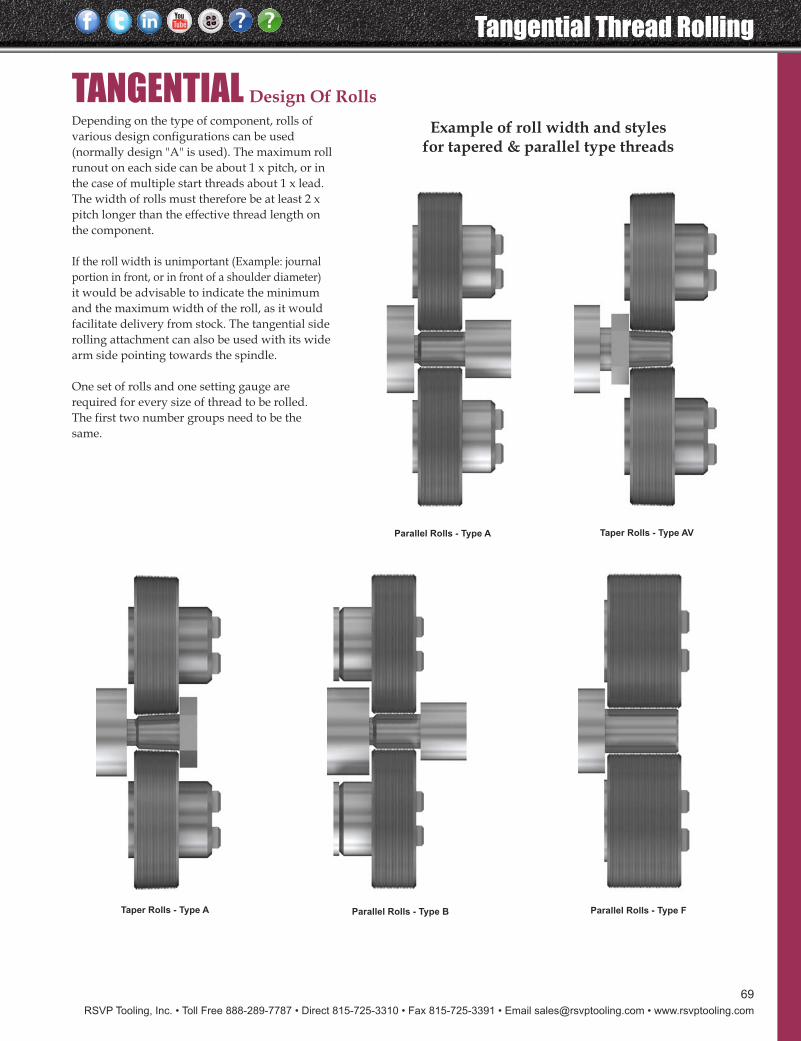
RSVP Tooling, Inc. • Toll Free 888-289-7787 • Direct 815-725-3310 • Fax 815-725-3391 • Email [email protected] • www.rsvptooling.com
69
Tangential Thread Rolling
TANGENTIAL Design Of RollsDepending on the type of component, rolls ofvarious design configurations can be used(normally design "A" is used). The maximum rollrunout on each side can be about 1 x pitch, or inthe case of multiple start threads about 1 x lead.The width of rolls must therefore be at least 2 xpitch longer than the effective thread length onthe component.
If the roll width is unimportant (Example: journalportion in front, or in front of a shoulder diameter)it would be advisable to indicate the minimumand the maximum width of the roll, as it wouldfacilitate delivery from stock. The tangential siderolling attachment can also be used with its widearm side pointing towards the spindle.
One set of rolls and one setting gauge arerequired for every size of thread to be rolled.The first two number groups need to be thesame.
Example of roll width and styles for tapered & parallel type threads
Parallel Rolls - Type B Parallel Rolls - Type FTaper Rolls - Type A
Taper Rolls - Type AVParallel Rolls - Type A
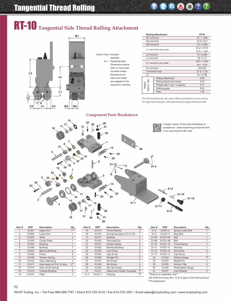
Tangential Thread Rolling
RSVP Tooling, Inc. • Toll Free 888-289-7787 • Direct 815-725-3310 • Fax 815-725-3391 • Email [email protected] • www.rsvptooling.com
RT-10 Tangential Side Thread Rolling Attachment
Dmax =max. shoulder
diameter
Av = Operating feed
Dimensions above
refer to cross slide
mounted holder.
Dimensions for
other tool holder
are adapted to the
respective machine.
W1
L3
L2
d
C2 C1 C2 W3 W2
L1
L4
31-4
4
36
20
20
331-1
31-11
31-3
336
3524
31-12
107
22
7
15
1717
18
813
3
21
2526
13
8
12
1611
2435
533
2210
17
17
2118 26
2020
25
30
41
28
9
2
14
31-2
31-10
31-13
14
1
30
41
28
15
Component Parts Breakdown
Item # EDP Description Qty
1 10-001 Upper Arm 1**
2 10-002 Lower Arm 1
3 10-003 Shaft 2
4 10-004 Center Shaft 1
5 10-005 Bushing 1
6 10-006 Bushing 1
7 10-007 Bearing Bushing 2
8 10-008 Pinion 2
9 10-009 Tension Spring 1
10 10-010 Gear w/Bushing 2
11 10-011 Gear (assy w/12 & 16 only) 0**
12 10-012 Gear w/Coil Spring 1
13 10-013 Carbide Bushing 2
14 10-014 Plate 2
Item # EDP Description Qty
15 10-015 Thrust Washer 2
16 10-016 Coil spring (assy w/11 & 12) 1
17 10-017 Bushing 4
20 10-020 Flat Head Scr. 4
21 10-021 Grease Nipple 2
22 10-022 Bearing Bushing 2
24 10-024 Cap Screw 2
25 10-025 Cap Screw 2
26 10-026 Straight Pin 2
27 10-027 Set Screw 1
28 10-028 Set Screw 2
30 10-030 Adj. Set Screw 2
31 10-031 Attachment Holder Complete 1t
31-1 10-031-1 Housing 1t
Item # EDP Description Qty
31-2 10-031-2 Spring Loded Bolt 1
31-3 10-031-3 Stop Bolt 1
31-4A 10-031-4A Bolt 1
31-4B 10-031-4B Bolt 1
31-10 10-031-10 Thrust Spring 1
31-11 10-031-11 Hex Nut 1
31-12 10-031-12 Set Screw 2
31-13 10-031-13 Cap Screw 1
32 10-032 Setting Gauge 1t
33 10-033 Slotted Pin 2
35 10-035 Schnorr Clip 2
36 10-036 Sheet Metal Gauge 1
41 10-041 Lock Washer 2
**Sold as an assembly only**
"(#1 & #2 Arm Assy) (#11,12 & 16 gear w/Coil Spring Assy)"t Per Application
Roiling Attachment RT10
W1 mm/inch 43 / 1 .693
W2 mm/inch 15.5 / 0.61
W3 mm/inch 7.2 / 0.283
L1 mm/ Inch min./max.23.2 / 0.913
27.6 / 1.087
L2 mm/inch 10 / 0.394
L3 mm/inch 80 / 3.15
C1 mm/inch min./max.26.5 / 1.043
40 / 1.575
C2 mm/inch 14/0.551
d mm/inch max. 31.5 / 1.24
L4 70 / 2.756
Rolling Attachment 0.65
Roiling Attachment Holder 0.75
Thread rolls (1 set = 2 pieces) 0.17
Setting gauge 0.05
Total 1.62
For left hand threads, the same rolling attachment can be used asfor right hand threads. Left hand threads require left hand rolls.
Weig
ht
Appro
x.
(kg)
A larger version of this parts breakdown is
available at - www.rsvptooling.com/prints.html
or by scanning this QR code.
70
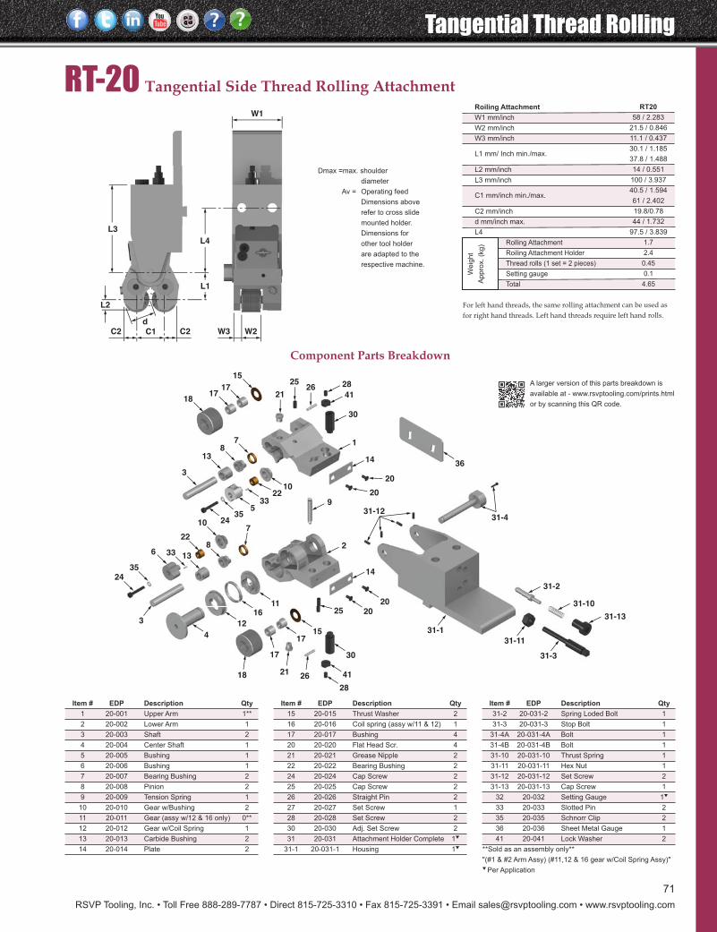
RSVP Tooling, Inc. • Toll Free 888-289-7787 • Direct 815-725-3310 • Fax 815-725-3391 • Email [email protected] • www.rsvptooling.com
71
Dmax =max. shoulder
diameter
Av = Operating feed
Dimensions above
refer to cross slide
mounted holder.
Dimensions for
other tool holder
are adapted to the
respective machine.
W1
L3
L2
d
C2 C1 C2 W3 W2
L1
L4
RT-20 Tangential Side Thread Rolling Attachment
31-4
4
36
20
20
331-1
31-11
31-3
336
3524
31-12
107
22
7
15
1717
18
813
3
21
2526
13
8
12
1611
2435
533
2210
17
17
2118 26
2020
25
30
41
28
9
2
14
31-2
31-10
31-13
14
1
30
41
28
15
Roiling Attachment RT20
W1 mm/inch 58 / 2.283
W2 mm/inch 21.5 / 0.846
W3 mm/inch 11.1 / 0.437
L1 mm/ Inch min./max.30.1 / 1.185
37.8 / 1.488
L2 mm/inch 14 / 0.551
L3 mm/inch 100 / 3.937
C1 mm/inch min./max.40.5 / 1.594
61 / 2.402
C2 mm/inch 19.8/0.78
d mm/inch max. 44 / 1.732
L4 97.5 / 3.839
Rolling Attachment 1.7
Roiling Attachment Holder 2.4
Thread rolls (1 set = 2 pieces) 0.45
Setting gauge 0.1
Total 4.65
For left hand threads, the same rolling attachment can be used asfor right hand threads. Left hand threads require left hand rolls.
Weig
ht
Appro
x.
(kg)
Component Parts Breakdown
Item # EDP Description Qty
1 20-001 Upper Arm 1**
2 20-002 Lower Arm 1
3 20-003 Shaft 2
4 20-004 Center Shaft 1
5 20-005 Bushing 1
6 20-006 Bushing 1
7 20-007 Bearing Bushing 2
8 20-008 Pinion 2
9 20-009 Tension Spring 1
10 20-010 Gear w/Bushing 2
11 20-011 Gear (assy w/12 & 16 only) 0**
12 20-012 Gear w/Coil Spring 1
13 20-013 Carbide Bushing 2
14 20-014 Plate 2
Item # EDP Description Qty
15 20-015 Thrust Washer 2
16 20-016 Coil spring (assy w/11 & 12) 1
17 20-017 Bushing 4
20 20-020 Flat Head Scr. 4
21 20-021 Grease Nipple 2
22 20-022 Bearing Bushing 2
24 20-024 Cap Screw 2
25 20-025 Cap Screw 2
26 20-026 Straight Pin 2
27 20-027 Set Screw 1
28 20-028 Set Screw 2
30 20-030 Adj. Set Screw 2
31 20-031 Attachment Holder Complete 1t
31-1 20-031-1 Housing 1t
Item # EDP Description Qty
31-2 20-031-2 Spring Loded Bolt 1
31-3 20-031-3 Stop Bolt 1
31-4A 20-031-4A Bolt 1
31-4B 20-031-4B Bolt 1
31-10 20-031-10 Thrust Spring 1
31-11 20-031-11 Hex Nut 1
31-12 20-031-12 Set Screw 2
31-13 20-031-13 Cap Screw 1
32 20-032 Setting Gauge 1t
33 20-033 Slotted Pin 2
35 20-035 Schnorr Clip 2
36 20-036 Sheet Metal Gauge 1
41 20-041 Lock Washer 2
**Sold as an assembly only**
"(#1 & #2 Arm Assy) (#11,12 & 16 gear w/Coil Spring Assy)"t Per Application
A larger version of this parts breakdown is
available at - www.rsvptooling.com/prints.html
or by scanning this QR code.
Tangential Thread Rolling
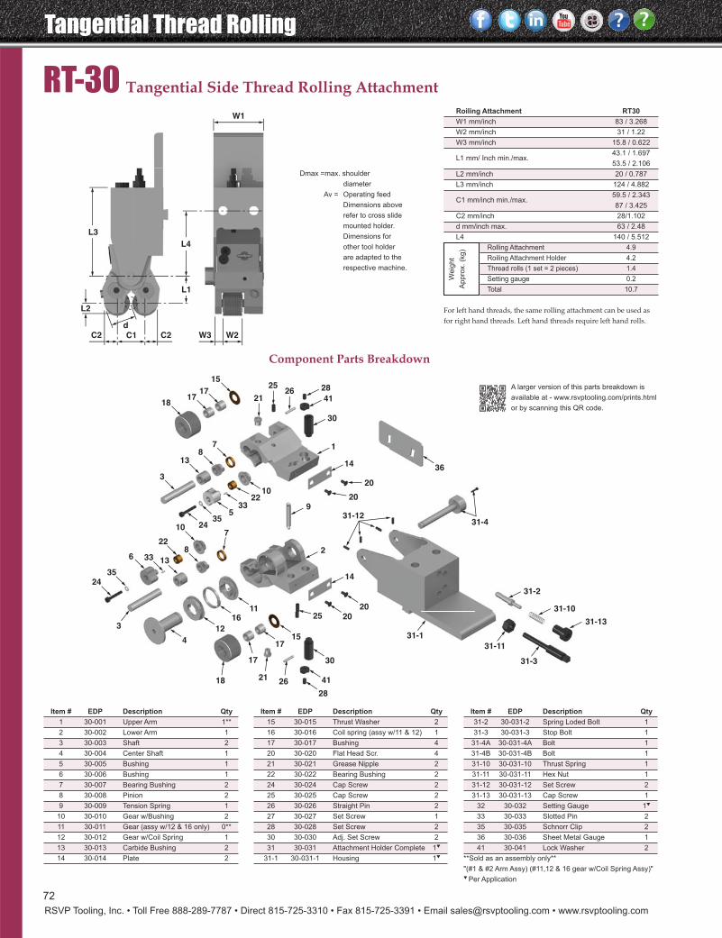
Tangential Thread Rolling
RSVP Tooling, Inc. • Toll Free 888-289-7787 • Direct 815-725-3310 • Fax 815-725-3391 • Email [email protected] • www.rsvptooling.com
RT-30 Tangential Side Thread Rolling Attachment
31-4
4
36
20
20
331-1
31-11
31-3
336
3524
31-12
107
22
7
15
1717
18
813
3
21
2526
13
8
12
1611
2435
533
2210
17
17
2118 26
2020
25
30
41
28
9
2
14
31-2
31-10
31-13
14
1
30
41
28
15
Component Parts Breakdown
Item # EDP Description Qty
1 30-001 Upper Arm 1**
2 30-002 Lower Arm 1
3 30-003 Shaft 2
4 30-004 Center Shaft 1
5 30-005 Bushing 1
6 30-006 Bushing 1
7 30-007 Bearing Bushing 2
8 30-008 Pinion 2
9 30-009 Tension Spring 1
10 30-010 Gear w/Bushing 2
11 30-011 Gear (assy w/12 & 16 only) 0**
12 30-012 Gear w/Coil Spring 1
13 30-013 Carbide Bushing 2
14 30-014 Plate 2
Item # EDP Description Qty
15 30-015 Thrust Washer 2
16 30-016 Coil spring (assy w/11 & 12) 1
17 30-017 Bushing 4
20 30-020 Flat Head Scr. 4
21 30-021 Grease Nipple 2
22 30-022 Bearing Bushing 2
24 30-024 Cap Screw 2
25 30-025 Cap Screw 2
26 30-026 Straight Pin 2
27 30-027 Set Screw 1
28 30-028 Set Screw 2
30 30-030 Adj. Set Screw 2
31 30-031 Attachment Holder Complete 1t
31-1 30-031-1 Housing 1t
Item # EDP Description Qty
31-2 30-031-2 Spring Loded Bolt 1
31-3 30-031-3 Stop Bolt 1
31-4A 30-031-4A Bolt 1
31-4B 30-031-4B Bolt 1
31-10 30-031-10 Thrust Spring 1
31-11 30-031-11 Hex Nut 1
31-12 30-031-12 Set Screw 2
31-13 30-031-13 Cap Screw 1
32 30-032 Setting Gauge 1t
33 30-033 Slotted Pin 2
35 30-035 Schnorr Clip 2
36 30-036 Sheet Metal Gauge 1
41 30-041 Lock Washer 2
**Sold as an assembly only**
"(#1 & #2 Arm Assy) (#11,12 & 16 gear w/Coil Spring Assy)"t Per Application
Roiling Attachment RT30
W1 mm/inch 83 / 3.268
W2 mm/inch 31 / 1.22
W3 mm/inch 15.8 / 0.622
L1 mm/ Inch min./max.43.1 / 1.697
53.5 / 2.106
L2 mm/inch 20 / 0.787
L3 mm/inch 124 / 4.882
C1 mm/inch min./max.59.5 / 2.343
87 / 3.425
C2 mm/inch 28/1.102
d mm/inch max. 63 / 2.48
L4 140 / 5.512
Rolling Attachment 4.9
Roiling Attachment Holder 4.2
Thread rolls (1 set = 2 pieces) 1.4
Setting gauge 0.2
Total 10.7
For left hand threads, the same rolling attachment can be used asfor right hand threads. Left hand threads require left hand rolls.
Weig
ht
Appro
x.
(kg)
Dmax =max. shoulder
diameter
Av = Operating feed
Dimensions above
refer to cross slide
mounted holder.
Dimensions for
other tool holder
are adapted to the
respective machine.
W1
L3
L2
d
C2 C1 C2 W3 W2
L1
L4
A larger version of this parts breakdown is
available at - www.rsvptooling.com/prints.html
or by scanning this QR code.
72
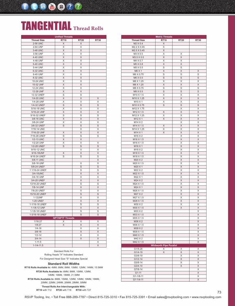
Tangential Thread Rolling
RSVP Tooling, Inc. • Toll Free 888-289-7787 • Direct 815-725-3310 • Fax 815-725-3391 • Email [email protected] • www.rsvptooling.com
73
TANGENTIAL Thread RollsUnified Threads
Thread Size RT10 RT20 RT30
2-56 UNC X X
2-64 UNF X X
3-48 UNC X X
3-56 UNF X X
4-40 UNC X X
4-48 UNF X X
5-40 UNC X X
5-44 UNF X X
6-32 UNC X X
6-40 UNF X X
8-32 UNC X X
10-24 UNC X X
10-32 UNF X X
12-24 UNC X X
12-28 UNF X X
12-32 UNEF S S
1/4-20 UNC X X X
1/4-28 UNF X X X
1/4-32 UNEF S S S
5/16-18 UNC X X X
5/16-24 UNF X X X
5/16-32 UNEF S S S
3/8-16 UNC X X X
3/8-24 UNF X X X
3/8-32 UNEF S S S
7/16-14 UNC X X
7/16-20 UNF X X X
7/16-28 UNEF S S S
1/2-13 UNC X X
1/2-20 UNF X X X
1/2-28 UNEF S S S
9/16-12 UNC X X
9/16-18UNF X X X
9/16-24 UNEF S S S
5/8-11 UNC X
5/8-18 UNF X X
5/8-24 UNEF S S
1 1/16-24 UNEF S S
3/4-10UNC X X
3/4-16 UNF X X
3/4-20 UNEF X X
13/16-20 UNEF S S
7/8-14 UNF X X
7/8-20 UNEF X X
15/16-20 UNEF S S
1-12UNF X X
1-20 UNEF X X
1-1/16-18 UNEF S S
1-1/8-12 UNF X X
1-1/8-18 UNEF S S
1-3/16-18 UNEF S S
NPT/NPTF Threads
1/16-27 X X X
1/8-27 X X X
1/4-18 X X
3/8-18 X X
1/2-14 X X
3/4-14 X X
1-11.5 X
1-1/4-11.5 X
Standard Rolls For
Rolling Heads "X" Indicates Standard
For Designed Head Size "S" Indicates Special
Standard Roll WidthsRT10 Rolls Available In: 4MM, 6MM, 8MM, 10MM, 12MM, 14MM, 15.5MM
RT20 Rolls Available In: 6MM, 8MM, 10MM, 12MM,
14MM, 16MM, 18MM, 21.5MM
RT30 Rolls Available In: 8MM, 10MM, 12MM, 14MM, 16MM, 18MM,
20MM, 22MM, 24MM, 26MM, 28MM, 30MM
Thread Rolls Are Interchangeable With:
RT10 with T12 RT20 with T18 RT30 with T27
Metric Threads
Thread Size RT10 RT20 RT30
M2 X 0.4 X
M2.2 X 0.45 X
M2.5 X 0.45 X
M3 X 0.5 X X
M3.5 X 0.5 X X
M4 X 0.7 X X
M5 X 0.8 X X
M5 X 0.5 S S
M6 X 1 X X X
M6 X 0.75 S S S
M6 X 0.5 S S S
M8 X 1.25 X X X
M8 X 1.25 X X X
M8 X 0.75 S S S
M8 X 0.5 S S S
M10 X 1.5 X X X
M10 X 1.25 X X X
M10 X 1 X X X
M10 X 0.75 S S S
M12 X 1.75 X X
M12 X 1.5 X X X
M12 X 1.25 X X X
M12 X 1 X X X
M14 X 2 X X
M14 X 1.5 X X X
M14 X 1.25 X X X
M14 X 1 X X X
M16 X 2 X X
M16 X 1.5 X X
M16 X 1.5 X X
M16 X 1 X X
M18 X 2 X X
M18 X 1.5 X X
M18 X 1.5 X X
M20 X 2 X X
M20 X 1.5 X X
M20 X 1 X X
M22 X 2 X X
M22 X 1.5 X X
M22 X 1 X X
M24 X 2 X X
M24 X 1.5 X X
M24 X 1 X X
M26 X 1.5 X X
M27 X 2 X X
M27 X 1.5 X X
M28 X 1.5 X X
M30 X 2 X X
M30 X 1.5 X X
M33 X 2 X
M33 X 1.5 X
M35 X 1.5 X
M36 X 2 X
M36 X 1.5 X
M39 X 2 X
M39 X 1.5 X
M40 X 1.5 X
M42 X 2 X
M42 X 1.5 X
Whitworth Pipe Parallel
G1/8-28 X X X
G1/4-19 X X X
G3/8-19 X X
G1/2-14 X X
G5/8-14 X X
G3/4-14 X X
G7/8-14 X
G1-11 X
G1-1/8-11 X
G1-1/4-11 X
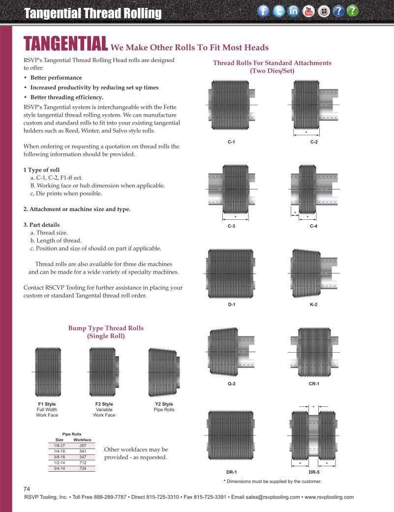
Tangential Thread Rolling
RSVP Tooling, Inc. • Toll Free 888-289-7787 • Direct 815-725-3310 • Fax 815-725-3391 • Email [email protected] • www.rsvptooling.com
We Make Other Rolls To Fit Most Heads
*
* *
***
*
C-1 C-2
C-3 C-4
D-1 K-2
Q-2
F1 StyleFull Width
Work Face
F2 StyleVariable
Work Face
Y2 Style
Pipe Rolls
CR-1
DR-1 DR-5
TANGENTIALRSVP's Tangential Thread Rolling Head rolls are designed to offer:
• Better performance• Increased productivity by reducing set up times• Better threading efficiency.RSVP's Tangential system is interchangeable with the Fettestyle tangential thread rolling system. We can manufacturecustom and standard rolls to fit into your existing tangentialholders such as Reed, Winter, and Salvo style rolls.
When ordering or requesting a quotation on thread rolls thefollowing information should be provided.
1 Type of rolla. C-1, C-2, F1-ff ect.B. Working face or hub dimension when applicable.c, Die prints when possible.
2. Attachment or machine size and type.
3. Part detailsa. Thread size.b. Length of thread.c. Position and size of should on part if applicable.
Thread rolls are also available for three die machinesand can be made for a wide variety of specialty machines.
Contact RSCVP Tooling for further assistance in placing yourcustom or standard Tangental thread roll order.
Thread Rolls For Standard Attachments(Two Dies/Set)
Bump Type Thread Rolls(Single Roll)
* Dimensions must be supplied by the customer.
Pipe Rolls
Size Workface
1/8-27 .357
1/4-18 .541
3/8-18 .547
1/2-14 .712
3/4-14 .724
Other workfaces may beprovided - as requested.
74
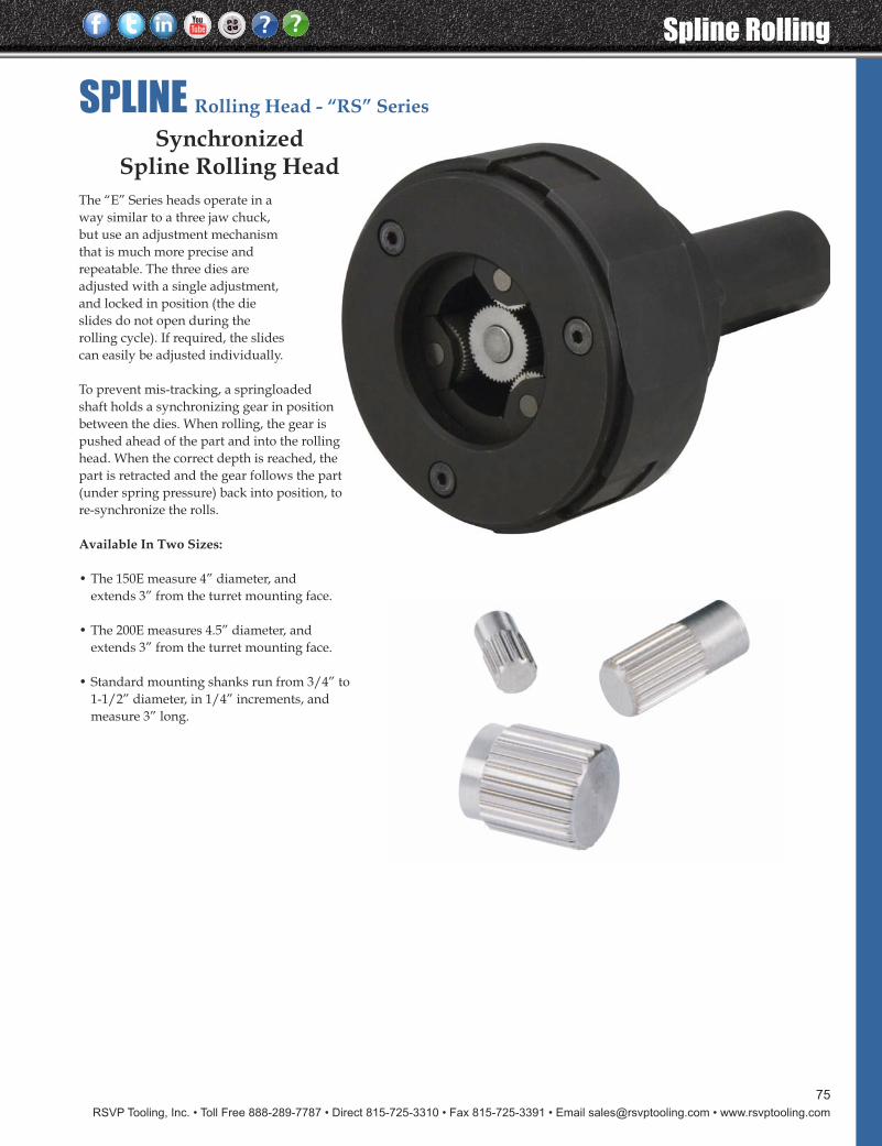
RSVP Tooling, Inc. • Toll Free 888-289-7787 • Direct 815-725-3310 • Fax 815-725-3391 • Email [email protected] • www.rsvptooling.com
75
The “E” Series heads operate in a way similar to a three jaw chuck, but use an adjustment mechanism that is much more precise and repeatable. The three dies are adjusted with a single adjustment, and locked in position (the die slides do not open during the rolling cycle). If required, the slides can easily be adjusted individually.
To prevent mis-tracking, a springloaded shaft holds a synchronizing gear in position between the dies. When rolling, the gear is pushed ahead of the part and into the rolling head. When the correct depth is reached, the part is retracted and the gear follows the part(under spring pressure) back into position, to re-synchronize the rolls.
Available In Two Sizes:
• The 150E measure 4” diameter, andextends 3” from the turret mounting face.
• The 200E measures 4.5” diameter, andextends 3” from the turret mounting face.
• Standard mounting shanks run from 3/4” to1-1/2” diameter, in 1/4” increments, andmeasure 3” long.
SynchronizedSpline Rolling Head
SPLINE Rolling Head - “RS” Series
Spline Rolling
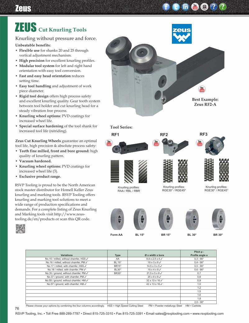
Zeus
RSVP Tooling, Inc. • Toll Free 888-289-7787 • Direct 815-725-3310 • Fax 815-725-3391 • Email [email protected] • www.rsvptooling.com
Best Example: Zeus RF2-A
Knurling profiles:
RAA / RBL / RBR
RF1 RF2 RF3
Knurling profiles:
RGE30° / RGE45°
Knurling profiles:
RGE30° / RGE45°
Knurling without pressure and force.Unbeatable benefits:• Flexible use for shanks 20 and 25 through
vertical adjustment mechanism.• High precision for excellent knurling profiles.• Modular tool system for left and right hand
orientation with easy tool conversion.• Fast and easy head orientation reduces
setting time.• Easy tool handling and adjustment of work
piece diameter.• Rigid tool design offers high process safety
and excellent knurling quality. Gear tooth systembetween tool holder and cut knurling head for asteady vibration free process.
• Knurling wheel options: PVD coatings forincreased wheel life.
• Special surface hardening of the tool shank for increased tool life (nitriding).
Zeus Cut Knurling Wheels guarantee an optimaltool life, high precision & absolute process safety:• Teeth fine milled, front and bore ground: high
quality of knurling pattern.• Vacuum hardened.• Knurling wheel options: PVD coatings for
increased wheel life (3).• Exclusive product range.
Pitch p -
Variations Type Ø x width x bore Profile angle a
No.15 / milled, without chamfer, HSS ✓ AA 8,9 x 2,5 x 4 ✓ 0,3 - 90°
No.16 / milled, without chamfer, PM ✓ BL 15° 10 x 3 x 6 ✓ 0,4 - 90°
No.17 / milled, with chamfer, HSS ✓ BR15° 14,5 x 3 x 5 ✓ 0,5 - 90°
No.18 / milled, with chamfer, PM ✓ BL30° 15 x 4 x 8 ✓ 0,6 - 90°
No.35 / ground, without chamfer, PM ✓ BR30° 21,5 x 5 x 8 ✓ 0,7
No.37 / ground, with chamfer, PM ✓ 25 x 6 x 8 ✓ 0,8
No.55 / ground, without chamfer, HM ✓ 32 x 13 x 16 ✓ 0,9
No.57 / ground, with chamfer, HM ✓ 42 x 13 x 16 ✓ 1,0
1,2
1,5
1,6
1,8
2,0 - 90°
Please choose your options by combining the four columns accordingly. HSS = High Speed Cutting Steel PM = Powder metallurgy Steel HM = Carbide
Form AA BL 15° BR 15° BL 30° BR 30°
Tool Series:
ZEUS Cut Knurling Tools
RSVP Tooling is proud to be the North Americanstock master distributor for Homell Keller Zeusknurling and marking tools. RSVP Tooling offersknurling and marking tool solutions to meet a wide range of production specifications and demands. For a complete listing of Zeus Knurling and Marking tools visit http://www.zeus-tooling.de/en/products or scan this QR code.
76
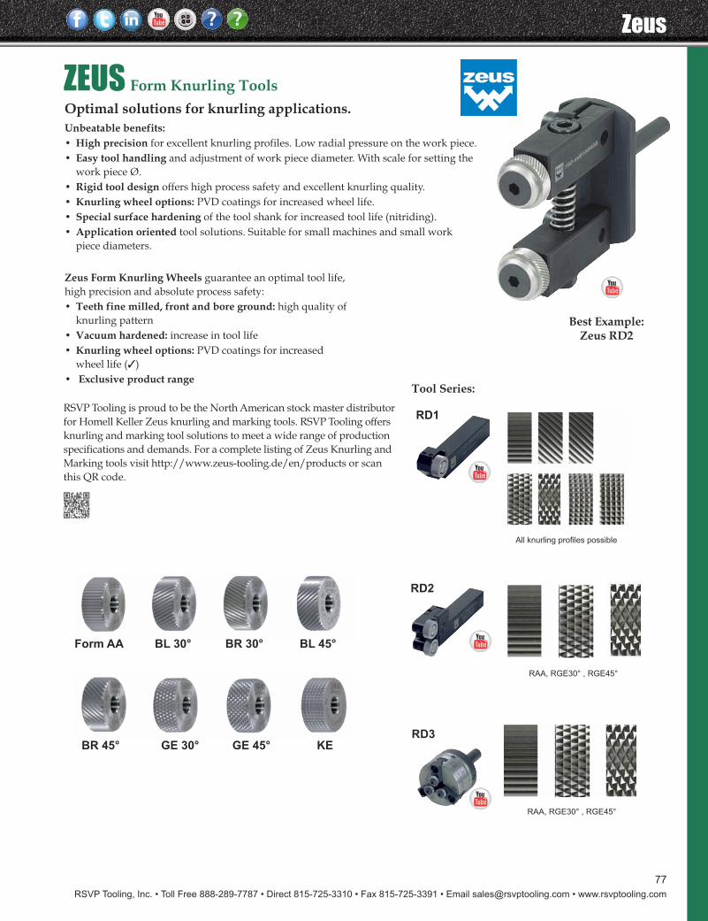
RSVP Tooling, Inc. • Toll Free 888-289-7787 • Direct 815-725-3310 • Fax 815-725-3391 • Email [email protected] • www.rsvptooling.com
77
Zeus
ZEUS Form Knurling ToolsOptimal solutions for knurling applications.Unbeatable benefits:• High precision for excellent knurling profiles. Low radial pressure on the work piece.• Easy tool handling and adjustment of work piece diameter. With scale for setting the
work piece Ø.• Rigid tool design offers high process safety and excellent knurling quality.• Knurling wheel options: PVD coatings for increased wheel life.• Special surface hardening of the tool shank for increased tool life (nitriding).• Application oriented tool solutions. Suitable for small machines and small work
piece diameters.
Tool Series:
All knurling profiles possible
RD1
RD2
RD3
RAA, RGE30° , RGE45°
RAA, RGE30° , RGE45°
Best Example: Zeus RD2
Zeus Form Knurling Wheels guarantee an optimal tool life, high precision and absolute process safety:• Teeth fine milled, front and bore ground: high quality of
knurling pattern• Vacuum hardened: increase in tool life• Knurling wheel options: PVD coatings for increased
wheel life (3)• Exclusive product range
Form AA BL 30° BR 30° BL 45°
BR 45° GE 30° GE 45° KE
RSVP Tooling is proud to be the North American stock master distributorfor Homell Keller Zeus knurling and marking tools. RSVP Tooling offersknurling and marking tool solutions to meet a wide range of productionspecifications and demands. For a complete listing of Zeus Knurling andMarking tools visit http://www.zeus-tooling.de/en/products or scanthis QR code.
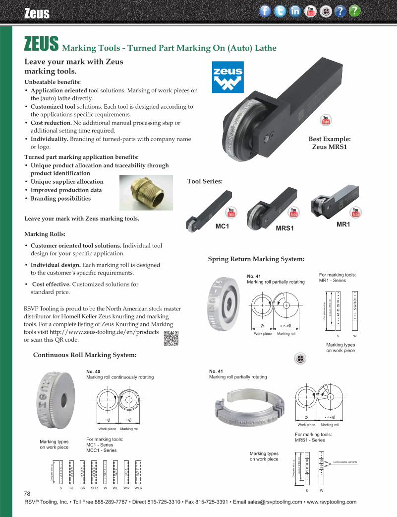
Zeus
RSVP Tooling, Inc. • Toll Free 888-289-7787 • Direct 815-725-3310 • Fax 815-725-3391 • Email [email protected] • www.rsvptooling.com
ZEUS Marking Tools - Turned Part Marking On (Auto) LatheLeave your mark with Zeus marking tools.Unbeatable benefits:• Application oriented tool solutions. Marking of work pieces on
the (auto) lathe directly.• Customized tool solutions. Each tool is designed according to
the applications specific requirements.• Cost reduction. No additional manual processing step or
additional setting time required.• Individuality. Branding of turned-parts with company name or logo.
Turned part marking application benefits:• Unique product allocation and traceability through
product identification• Unique supplier allocation• Improved production data• Branding possibilities
Tool Series:
MC1 MR1MRS1
Best Example: Zeus MRS1
Leave your mark with Zeus marking tools.
Marking Rolls:
• Customer oriented tool solutions. Individual tooldesign for your specific application.
• Individual design. Each marking roll is designedto the customer's specific requirements.
• Cost effective. Customized solutions forstandard price.
Continuous Roll Marking System:
No. 40Marking roll continuously rotating
For marking tools:
MC1 - Series
MCC1 - Series
For marking tools:
MR1 - Series
For marking tools:
MRS1 - SeriesMarking types
on work piece
Marking types
on work piece
Marking types
on work piece
No. 41Marking roll partially rotating
No. 41
Marking roll partially rotating
Spring Return Marking System:
RSVP Tooling is proud to be the North American stock master distributor for Homell Keller Zeus knurling and markingtools. For a complete listing of Zeus Knurling and Markingtools visit http://www.zeus-tooling.de/en/productsor scan this QR code.
78

RSVP Tooling, Inc. • Toll Free 888-289-7787 • Direct 815-725-3310 • Fax 815-725-3391 • Email [email protected] • www.rsvptooling.com
79
Specialty Tools
BAUBLIES Precision Burnishing ToolsRSVP Tooling is proud to be the North Americansource for Baublies precision roller an diamondburnishing tools.
We offer a complete range of sizes and styles to suitany application regardless of how large or small.
Please contact us with your application and we willbe happy to provide a complete comprehensivesolution for you.
Complete product catalogs and video representationsare available at www.rsvptooling.com and followour link to Baublies Burnishing Tools.
Or contact our office directly and we will be able toassist you.
RSVP Tooling
Home Page
Baublies Burnishing Tools
Home Page
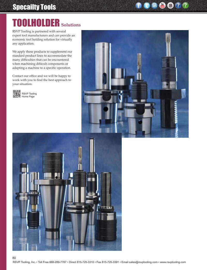
Specailty Tools
RSVP Tooling, Inc. • Toll Free 888-289-7787 • Direct 815-725-3310 • Fax 815-725-3391 • Email [email protected] • www.rsvptooling.com
80
TOOLHOLDER SolutionsRSVP Tooling is partnered with severalexpert tool manufacturers and can provide aneconomic tool holding solution for virtuallyany application.
We apply these products to supplement ourstandard product lines to accommodate themany difficulties that can be encounteredwhen machining difiicult components oradapting a machine to a specific operation.
Contact our office and we will be happy towork with you to find the best approach toyour situation.
RSVP Tooling
Home Page

RSVP Tooling, Inc.Toll Free: 888-289-7787
Direct: 815-725-3310
Fax: 815-725-3391
Email: [email protected]
www.rsvptooling.comContact
Information
Website
Link
Related Documents