Guide to “The Risø TL/OSL Reader” DTU Nutech, Denmark August 2015

Welcome message from author
This document is posted to help you gain knowledge. Please leave a comment to let me know what you think about it! Share it to your friends and learn new things together.
Transcript
Guide to
“The Risø TL/OSL Reader”
DTU Nutech, DenmarkAugust 2015
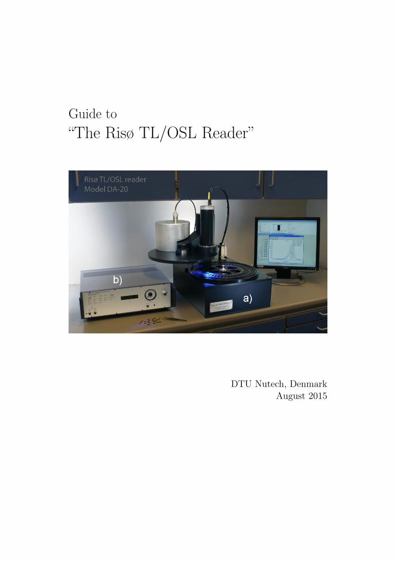
Precautions!• Do not remove the signal cable before removing the HV cable from
the PMT! Removing the signal cable while HV is connected maydamage the amplifier inside the PMT. When the lid is open the HVis switched off automatically.
• Do not heat samples on aluminum discs higher than 500 ◦C! If thealuminum disc is heated above 500 ◦C it will be in risk of melting,and the heating element may be damaged. In the Sequence Editora maximum temperature can be set to prevent higher temperatures.
• Do not block the rear vacuum outlet when not using the quartzwindow! If the quartz window is not used e.g. for single grain, thevacuum outlet must not be connected or blocked in order to be ableto let out the excessive air in the chamber when closing the lid.
• Maximum sample height is 2 mm! If the sample is too high thecarousel may be jammed.
• Make sure the heater element is down, before closing the lid! Ifthe heater element is up, remove the carousel, and then close thelid. Connect with control program, and send lx command to theheater in the services tab. On later versions of Controller there isan audible alarm when the lid is closing while the heater lift is up.
• Acid fumes will seriously damage the reader! Severe corrosion andfailure in instrumentation will occur from contaminated laboratoryatmospheres or measurement of inadequately washed samples. It isvery important to avoid any possibility of acid-fume contaminationof the reader:
1. Make sure that the atmosphere in the room containing thereader is not connected to the air circulation in a chemistrypreparation room (e.g. through an air-conditioning circuit ora door).
2. Make sure that all acid-treated samples are thoroughly washedbefore loading into the reader. If in doubt, check the pH is >6.
Contents
List of Figures iv
1 Overview 1
2 The Risø TL/OSL Reader 52.1 Sample carousel . . . . . . . . . . . . . . . . . . . . . . . . . . 52.2 Light detection system . . . . . . . . . . . . . . . . . . . . . . 6
2.2.1 Photomultiplier tube . . . . . . . . . . . . . . . . . . . 62.2.2 Detection filters . . . . . . . . . . . . . . . . . . . . . . 7
2.3 Luminescence stimulation system . . . . . . . . . . . . . . . . 102.3.1 Heating system . . . . . . . . . . . . . . . . . . . . . . 102.3.2 Optical stimulation system . . . . . . . . . . . . . . . . 112.3.3 Calibration LED . . . . . . . . . . . . . . . . . . . . . 16
2.4 Irradiation sources . . . . . . . . . . . . . . . . . . . . . . . . 182.4.1 Beta irradiation . . . . . . . . . . . . . . . . . . . . . . 192.4.2 External dose rates . . . . . . . . . . . . . . . . . . . . 212.4.3 Alpha irradiation . . . . . . . . . . . . . . . . . . . . . 212.4.4 X-ray irradiation . . . . . . . . . . . . . . . . . . . . . 22
3 Installation of the Risø TL/OSL reader 233.1 Components . . . . . . . . . . . . . . . . . . . . . . . . . . . . 233.2 Installing the hardware . . . . . . . . . . . . . . . . . . . . . . 25
3.2.1 Unpacking . . . . . . . . . . . . . . . . . . . . . . . . . 253.2.2 Nitrogen connections . . . . . . . . . . . . . . . . . . . 263.2.3 Attaching the flow meter . . . . . . . . . . . . . . . . . 293.2.4 Mounting the PMT . . . . . . . . . . . . . . . . . . . . 293.2.5 Connecting to the Controller . . . . . . . . . . . . . . . 313.2.6 Connecting the N2/air supply to the beta irradiator
(not yet loaded) . . . . . . . . . . . . . . . . . . . . . . 333.3 Installing the Risø software package . . . . . . . . . . . . . . . 333.4 Testing . . . . . . . . . . . . . . . . . . . . . . . . . . . . . . . 36
CONTENTS iii
3.4.1 Resetting the sample carrousel . . . . . . . . . . . . . . 373.4.2 Checking the lift . . . . . . . . . . . . . . . . . . . . . 373.4.3 Checking the Blue LEDs . . . . . . . . . . . . . . . . . 383.4.4 Adjusting the N2 flow rate . . . . . . . . . . . . . . . . 383.4.5 Checking the beta irradiator . . . . . . . . . . . . . . . 383.4.6 Checking the alpha irradiator . . . . . . . . . . . . . . 383.4.7 Measure PMT counts . . . . . . . . . . . . . . . . . . . 38
3.5 Loading the beta source . . . . . . . . . . . . . . . . . . . . . 39
4 Changing detection filters 494.1 Mounting detection filters . . . . . . . . . . . . . . . . . . . . 494.2 Removing the PMT . . . . . . . . . . . . . . . . . . . . . . . . 494.3 Replacing the filter basket . . . . . . . . . . . . . . . . . . . . 514.4 Disabling the blue LEDs . . . . . . . . . . . . . . . . . . . . . 514.5 Reconnecting the PMT . . . . . . . . . . . . . . . . . . . . . . 514.6 Check for light leaks . . . . . . . . . . . . . . . . . . . . . . . 51
5 Optimising the Signal-to-Noise ratio 53
6 Dead time correction 58
7 Frequently answered questions 607.1 Power requirements . . . . . . . . . . . . . . . . . . . . . . . . 607.2 User PC requirements . . . . . . . . . . . . . . . . . . . . . . 607.3 Laboratory recommendations . . . . . . . . . . . . . . . . . . 617.4 Changing filters . . . . . . . . . . . . . . . . . . . . . . . . . . 627.5 Nitrogen requirements . . . . . . . . . . . . . . . . . . . . . . 637.6 Vacuum . . . . . . . . . . . . . . . . . . . . . . . . . . . . . . 637.7 Operation . . . . . . . . . . . . . . . . . . . . . . . . . . . . . 647.8 Maintenance and comments . . . . . . . . . . . . . . . . . . . 64
References 66

List of Figures
1.1 Schematic drawing of the Risø TL/OSL reader . . . . . . . . . 21.2 Schematic overview of the Risø system . . . . . . . . . . . . . 31.3 Picture of the Controller . . . . . . . . . . . . . . . . . . . . . 4
2.1 Discs, cups and sample carrousel . . . . . . . . . . . . . . . . 62.2 Quantum efficiency of 9235QB PMT . . . . . . . . . . . . . . 72.3 Emission spectra of sedimentary quartz and K feldspars . . . . 82.4 Detection filters . . . . . . . . . . . . . . . . . . . . . . . . . . 92.5 Detection filters and emissions . . . . . . . . . . . . . . . . . . 92.6 Picture of the heating element . . . . . . . . . . . . . . . . . . 102.7 Precision of the heater element . . . . . . . . . . . . . . . . . 112.8 Stimulation modes . . . . . . . . . . . . . . . . . . . . . . . . 122.9 Schematic diagram of the stimulation unit . . . . . . . . . . . 132.10 Picture of the OSL stimulation head . . . . . . . . . . . . . . 142.11 Blue LED emission spectrum and filter transmissions . . . . . 152.12 Calibration LED . . . . . . . . . . . . . . . . . . . . . . . . . 172.13 TL flange . . . . . . . . . . . . . . . . . . . . . . . . . . . . . 182.14 Pictures of the irradiators . . . . . . . . . . . . . . . . . . . . 192.15 Cross section of the beta irradiator . . . . . . . . . . . . . . . 20
3.1 Components . . . . . . . . . . . . . . . . . . . . . . . . . . . . 243.2 Unpacking the shipment . . . . . . . . . . . . . . . . . . . . . 263.3 N2 tubing . . . . . . . . . . . . . . . . . . . . . . . . . . . . . 273.4 Two separate compressed input sources . . . . . . . . . . . . . 283.5 Reduction Valve . . . . . . . . . . . . . . . . . . . . . . . . . . 303.6 PMT mounting . . . . . . . . . . . . . . . . . . . . . . . . . . 313.7 Connecting to the Controller . . . . . . . . . . . . . . . . . . . 323.8 Example of the Risø PM-Tube Testsheet . . . . . . . . . . . . 333.9 Connecting the N2/air supply to the beta irradiator . . . . . . 343.10 Software installation USB 1 . . . . . . . . . . . . . . . . . . . 353.11 Software installation USB 2 . . . . . . . . . . . . . . . . . . . 36
LIST OF FIGURES v
3.12 Testing the system using CONTROL . . . . . . . . . . . . . . 373.13 Removing the air tube . . . . . . . . . . . . . . . . . . . . . . 403.14 Removing Pb shielding . . . . . . . . . . . . . . . . . . . . . . 413.15 Removing the irradiator . . . . . . . . . . . . . . . . . . . . . 413.16 Preparing for loading/unloading . . . . . . . . . . . . . . . . . 423.17 Items in the irradiator . . . . . . . . . . . . . . . . . . . . . . 433.18 Removing the circlip . . . . . . . . . . . . . . . . . . . . . . . 433.19 Removing items in the irradiator . . . . . . . . . . . . . . . . 443.20 Inserting the source I . . . . . . . . . . . . . . . . . . . . . . . 453.21 Inserting the source II . . . . . . . . . . . . . . . . . . . . . . 463.22 Reinsert spacers . . . . . . . . . . . . . . . . . . . . . . . . . . 473.23 Mounting the circlip . . . . . . . . . . . . . . . . . . . . . . . 48
4.1 Mounting detection filters . . . . . . . . . . . . . . . . . . . . 50
5.1 Adjusting the HV of the PMT . . . . . . . . . . . . . . . . . . 545.2 Using CONTROL to determine optimal S/N . . . . . . . . . . 555.3 S/N ratio of the PMT . . . . . . . . . . . . . . . . . . . . . . 57
6.1 Dead time correction 1 . . . . . . . . . . . . . . . . . . . . . . 596.2 Dead time correction 2 . . . . . . . . . . . . . . . . . . . . . . 59
7.1 Disabling the LEDs . . . . . . . . . . . . . . . . . . . . . . . . 61
1
Overview
Essential components of the Risø TL/OSL reader (model TL/OSL-DA-20)are:
1) light detection system
2) luminescence stimulation system (thermal and optical )
3) irradiation source
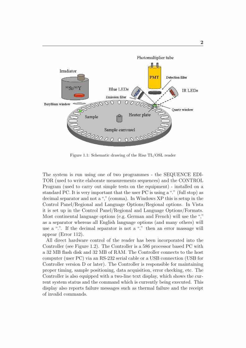
The light detection system comprises of a photomultiplier tube (PMT) incombination with suitable detection filters (see section 2.2). The lumines-cence stimulation system comprises of a heating element and an optical stim-ulation unit. Theses two facilities can be used separately or in combination(see section 2.3). In situ irradiation is achieved using either a beta source,an alpha source or an X-ray generator (see section 2.4).The Risø TL/OSL measurement system enables measurement of both ther-moluminescence and optically stimulated luminescence. The system allowsup to 48 samples to be individually heated to any temperature between roomtemperature and 700◦C, to be individually irradiated (using alpha, beta orX-ray radiation) and to be optically stimulated by various light sources insitu. The measurements are carried out in a vacuum chamber. The emittedluminescence is measured by a light detection system comprised of a pho-tomultiplier tube and suitable detection filters. A schematic drawing of thesystem is shown in Figure 1.1.
The Risø TL/OSL reader consists of two separate units:
a) The Reader (hardware; a) picture title page)
b) The Controller (Control of hardware, PMT preamplifier etc.; b) picturetitle page)
2
Figure 1.1: Schematic drawing of the Risø TL/OSL reader
The system is run using one of two programmes - the SEQUENCE EDI-TOR (used to write elaborate measurements sequences) and the CONTROLProgram (used to carry out simple tests on the equipment) - installed on astandard PC. It is very important that the user PC is using a“.” (full stop) asdecimal separator and not a“,” (comma). In Windows XP this is setup in theControl Panel/Regional and Language Options/Regional options. In Vistait is set up in the Control Panel/Regional and Language Options/Formats.Most continental language options (e.g. German and French) will use the “,”as a separator whereas all English language options (and many others) willuse a “.”. If the decimal separator is not a “.” then an error massage willappear (Error 112).
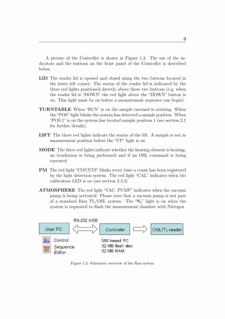
All direct hardware control of the reader has been incorporated into theController (see Figure 1.2). The Controller is a 586 processor based PC witha 32 MB flash disk and 32 MB of RAM. The Controller connects to the hostcomputer (user PC) via an RS-232 serial cable or a USB connection (USB forController version D or later). The Controller is responsible for maintainingproper timing, sample positioning, data acquisition, error checking, etc. TheController is also equipped with a two-line text display, which shows the cur-rent system status and the command which is currently being executed. Thisdisplay also reports failure messages such as thermal failure and the receiptof invalid commands.
3
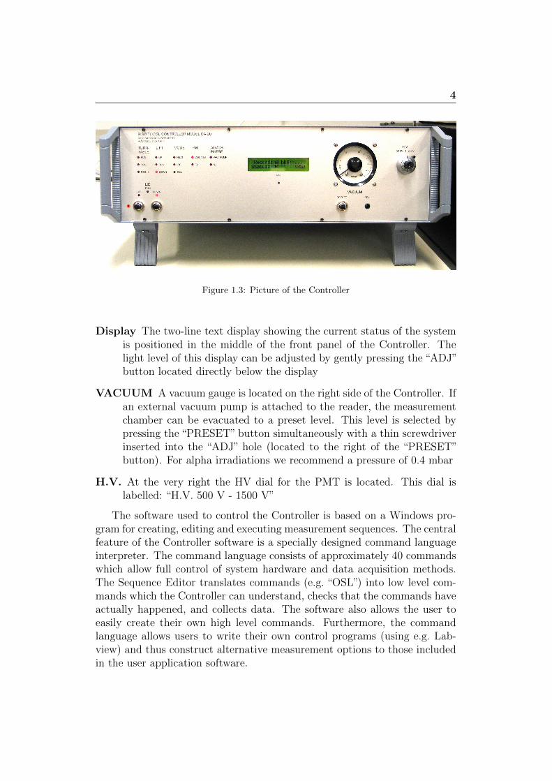
A picture of the Controller is shown in Figure 1.3. The use of the in-dicators and the buttons on the front panel of the Controller is describedbelow.
LID The reader lid is opened and closed using the two buttons located inthe lower left corner. The status of the reader lid is indicated by thethree red lights positioned directly above these two buttons (e.g. whenthe reader lid is “DOWN” the red light above the “DOWN” button ison. This light must be on before a measurement sequence can begin)
TURNTABLE When “RUN” is on the sample carousel is rotating. Whenthe“POS”light blinks the system has detected a sample position. When“POS.1” is on the system has located sample position 1 (see section 2.1for further details)
LIFT The three red lights indicate the status of the lift. A sample is not inmeasurement position before the “UP” light is on
MODE The three red lights indicate whether the heating element is heating,an irradiation is being performed and if an OSL command is beingexecuted
PM The red light “COUNTS” blinks every time a count has been registeredby the light detection system. The red light “CAL” indicates when thecalibration LED is on (see section 2.3.3)
ATMOSPHERE The red light “VAC. PUMP” indicates when the vacuumpump is being activated. Please note that a vacuum pump is not partof a standard Risø TL/OSL system. The “N2” light is on when thesystem is requested to flush the measurement chamber with Nitrogen
Figure 1.2: Schematic overview of the Risø system
4
Figure 1.3: Picture of the Controller
Display The two-line text display showing the current status of the systemis positioned in the middle of the front panel of the Controller. Thelight level of this display can be adjusted by gently pressing the “ADJ”button located directly below the display
VACUUM A vacuum gauge is located on the right side of the Controller. Ifan external vacuum pump is attached to the reader, the measurementchamber can be evacuated to a preset level. This level is selected bypressing the “PRESET” button simultaneously with a thin screwdriverinserted into the “ADJ” hole (located to the right of the “PRESET”button). For alpha irradiations we recommend a pressure of 0.4 mbar
H.V. At the very right the HV dial for the PMT is located. This dial islabelled: “H.V. 500 V - 1500 V”
The software used to control the Controller is based on a Windows pro-gram for creating, editing and executing measurement sequences. The centralfeature of the Controller software is a specially designed command languageinterpreter. The command language consists of approximately 40 commandswhich allow full control of system hardware and data acquisition methods.The Sequence Editor translates commands (e.g. “OSL”) into low level com-mands which the Controller can understand, checks that the commands haveactually happened, and collects data. The software also allows the user toeasily create their own high level commands. Furthermore, the commandlanguage allows users to write their own control programs (using e.g. Lab-view) and thus construct alternative measurement options to those includedin the user application software.
2
The Risø TL/OSL Reader
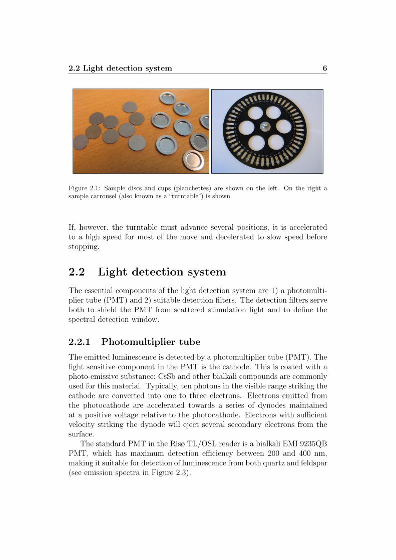
Samples are either mounted on 9.7 mm diameter stainless steel discs usingsilicone oil as an adhesive or poured (as loose grains) into sample cups (seeFigure 2.1). Samples are loaded onto an exchangeable sample carousel thatcan accommodate up to 48 samples. The sample carousel is placed in thesample chamber which can be programmed to be evacuated or have a nitro-gen atmosphere maintained by a nitrogen flow.
The sample is lifted through slots in the sample carousel into the mea-surement position by a lift, which also functions as heating element. In themeasurement position the sample can be stimulated thermally and/or opti-cally. Thermal stimulation is obtained by linearly increasing the temperatureof the heating element and optical stimulation is provided by different lightsources focused onto the sample position. The emitted luminescence is mea-sured by the light detection system.
2.1 Sample carousel
The sample carousel rests on a motor driven turntable, which enables rota-tion of the sample carousel. Rotation is computer controlled and positionholes drilled though the carousel in close proximity to the sample positionsenable the system to keep track of the position of the carousel using opto-electronics. An infrared light emitting diode (LED) is positioned underneaththe turntable, which is switched on during rotation. The measurement is ini-tiated by moving a given sample to the measurement position located directlyunderneath the light detection system. The sample carrousel rotates at twodifferent speeds (two-speed turntable) to reduce processing time. If a sampleis moved to the next position then the turntable turns at the normal speed.
2.2 Light detection system 6
Figure 2.1: Sample discs and cups (planchettes) are shown on the left. On the right asample carrousel (also known as a “turntable”) is shown.
If, however, the turntable must advance several positions, it is acceleratedto a high speed for most of the move and decelerated to slow speed beforestopping.
2.2 Light detection system
The essential components of the light detection system are 1) a photomulti-plier tube (PMT) and 2) suitable detection filters. The detection filters serveboth to shield the PMT from scattered stimulation light and to define thespectral detection window.
2.2.1 Photomultiplier tube
The emitted luminescence is detected by a photomultiplier tube (PMT). Thelight sensitive component in the PMT is the cathode. This is coated with aphoto-emissive substance; CsSb and other bialkali compounds are commonlyused for this material. Typically, ten photons in the visible range striking thecathode are converted into one to three electrons. Electrons emitted fromthe photocathode are accelerated towards a series of dynodes maintainedat a positive voltage relative to the photocathode. Electrons with sufficientvelocity striking the dynode will eject several secondary electrons from thesurface.
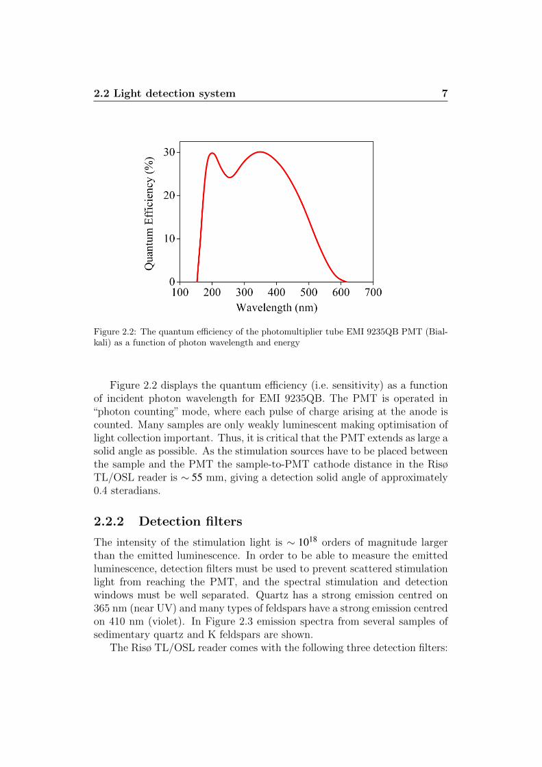
The standard PMT in the Risø TL/OSL reader is a bialkali EMI 9235QBPMT, which has maximum detection efficiency between 200 and 400 nm,making it suitable for detection of luminescence from both quartz and feldspar(see emission spectra in Figure 2.3).
2.2 Light detection system 7
Figure 2.2: The quantum efficiency of the photomultiplier tube EMI 9235QB PMT (Bial-kali) as a function of photon wavelength and energy
Figure 2.2 displays the quantum efficiency (i.e. sensitivity) as a functionof incident photon wavelength for EMI 9235QB. The PMT is operated in“photon counting” mode, where each pulse of charge arising at the anode iscounted. Many samples are only weakly luminescent making optimisation oflight collection important. Thus, it is critical that the PMT extends as large asolid angle as possible. As the stimulation sources have to be placed betweenthe sample and the PMT the sample-to-PMT cathode distance in the RisøTL/OSL reader is ∼ 55 mm, giving a detection solid angle of approximately0.4 steradians.
2.2.2 Detection filters
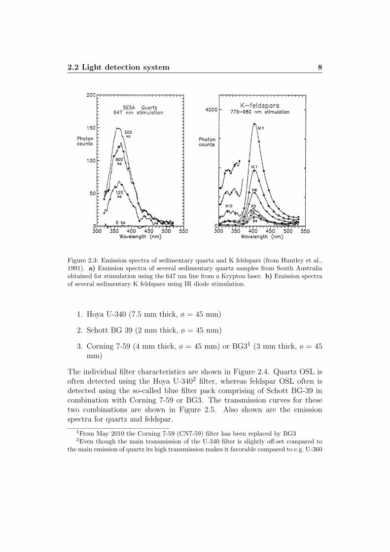
The intensity of the stimulation light is ∼ 1018 orders of magnitude largerthan the emitted luminescence. In order to be able to measure the emittedluminescence, detection filters must be used to prevent scattered stimulationlight from reaching the PMT, and the spectral stimulation and detectionwindows must be well separated. Quartz has a strong emission centred on365 nm (near UV) and many types of feldspars have a strong emission centredon 410 nm (violet). In Figure 2.3 emission spectra from several samples ofsedimentary quartz and K feldspars are shown.
The Risø TL/OSL reader comes with the following three detection filters:
2.2 Light detection system 8
Figure 2.3: Emission spectra of sedimentary quartz and K feldspars (from Huntley et al.,1991). a) Emission spectra of several sedimentary quartz samples from South Australiaobtained for stimulation using the 647 nm line from a Krypton laser. b) Emission spectraof several sedimentary K feldspars using IR diode stimulation.
1. Hoya U-340 (7.5 mm thick, ø = 45 mm)
2. Schott BG 39 (2 mm thick, ø = 45 mm)
3. Corning 7-59 (4 mm thick, ø = 45 mm) or BG31 (3 mm thick, ø = 45mm)
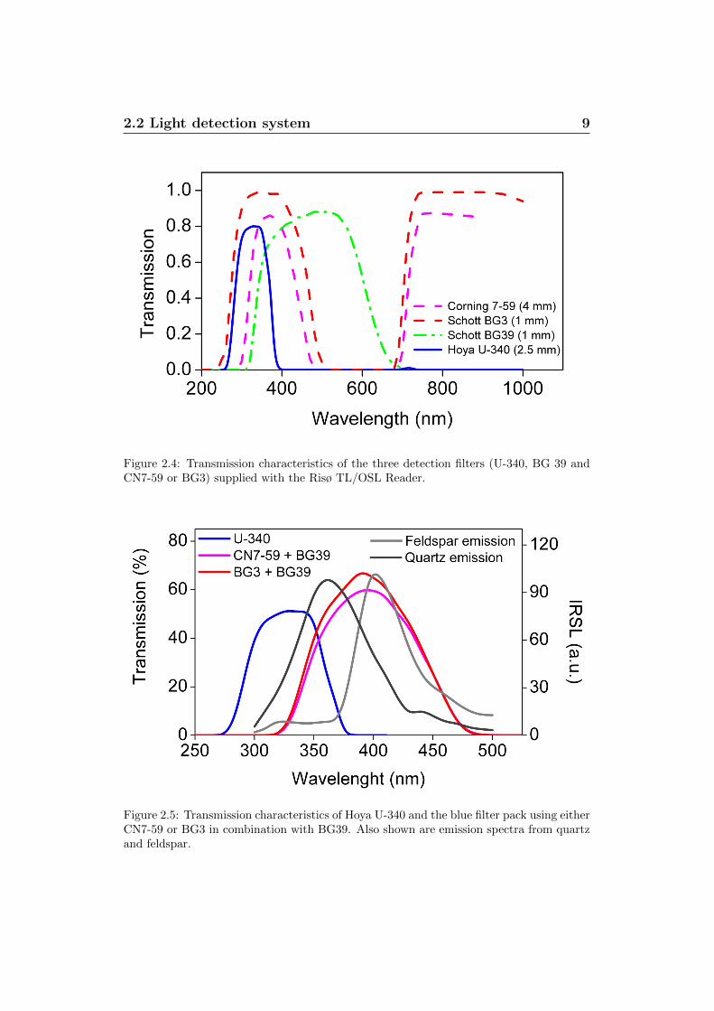
The individual filter characteristics are shown in Figure 2.4. Quartz OSL isoften detected using the Hoya U-3402 filter, whereas feldspar OSL often isdetected using the so-called blue filter pack comprising of Schott BG-39 incombination with Corning 7-59 or BG3. The transmission curves for thesetwo combinations are shown in Figure 2.5. Also shown are the emissionspectra for quartz and feldspar.
1From May 2010 the Corning 7-59 (CN7-59) filter has been replaced by BG32Even though the main transmission of the U-340 filter is slightly off-set compared to
the main emission of quartz its high transmission makes it favorable compared to e.g. U-360
2.2 Light detection system 9
Figure 2.4: Transmission characteristics of the three detection filters (U-340, BG 39 andCN7-59 or BG3) supplied with the Risø TL/OSL Reader.
Figure 2.5: Transmission characteristics of Hoya U-340 and the blue filter pack using eitherCN7-59 or BG3 in combination with BG39. Also shown are emission spectra from quartzand feldspar.
2.3 Luminescence stimulation system 10
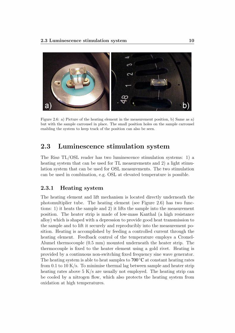
Figure 2.6: a) Picture of the heating element in the measurement position, b) Same as a)but with the sample carrousel in place. The small position holes on the sample carrouselenabling the system to keep track of the position can also be seen.
2.3 Luminescence stimulation system
The Risø TL/OSL reader has two luminescence stimulation systems: 1) aheating system that can be used for TL measurements and 2) a light stimu-lation system that can be used for OSL measurements. The two stimulationcan be used in combination, e.g. OSL at elevated temperature is possible.
2.3.1 Heating system
The heating element and lift mechanism is located directly underneath thephotomultiplier tube. The heating element (see Figure 2.6) has two func-tions: 1) it heats the sample and 2) it lifts the sample into the measurementposition. The heater strip is made of low-mass Kanthal (a high resistancealloy) which is shaped with a depression to provide good heat transmission tothe sample and to lift it securely and reproducibly into the measurement po-sition. Heating is accomplished by feeding a controlled current through theheating element. Feedback control of the temperature employs a Cromel-Alumel thermocouple (0.5 mm) mounted underneath the heater strip. Thethermocouple is fixed to the heater element using a gold rivet. Heating isprovided by a continuous non-switching fixed frequency sine wave generator.The heating system is able to heat samples to 700◦C at constant heating ratesfrom 0.1 to 10 K/s. To minimise thermal lag between sample and heater stripheating rates above 5 K/s are usually not employed. The heating strip canbe cooled by a nitrogen flow, which also protects the heating system fromoxidation at high temperatures.
2.3 Luminescence stimulation system 11
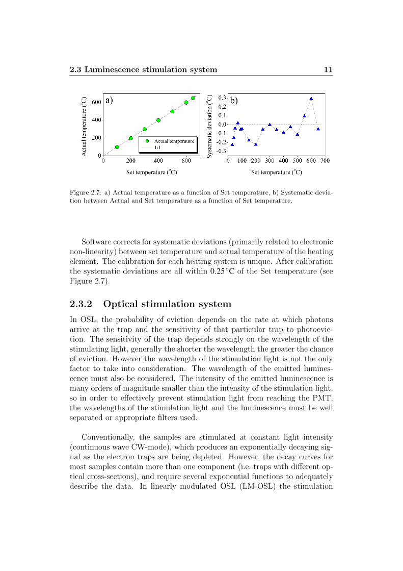
Figure 2.7: a) Actual temperature as a function of Set temperature, b) Systematic devia-tion between Actual and Set temperature as a function of Set temperature.
Software corrects for systematic deviations (primarily related to electronicnon-linearity) between set temperature and actual temperature of the heatingelement. The calibration for each heating system is unique. After calibrationthe systematic deviations are all within 0.25◦C of the Set temperature (seeFigure 2.7).
2.3.2 Optical stimulation system
In OSL, the probability of eviction depends on the rate at which photonsarrive at the trap and the sensitivity of that particular trap to photoevic-tion. The sensitivity of the trap depends strongly on the wavelength of thestimulating light, generally the shorter the wavelength the greater the chanceof eviction. However the wavelength of the stimulation light is not the onlyfactor to take into consideration. The wavelength of the emitted lumines-cence must also be considered. The intensity of the emitted luminescence ismany orders of magnitude smaller than the intensity of the stimulation light,so in order to effectively prevent stimulation light from reaching the PMT,the wavelengths of the stimulation light and the luminescence must be wellseparated or appropriate filters used.
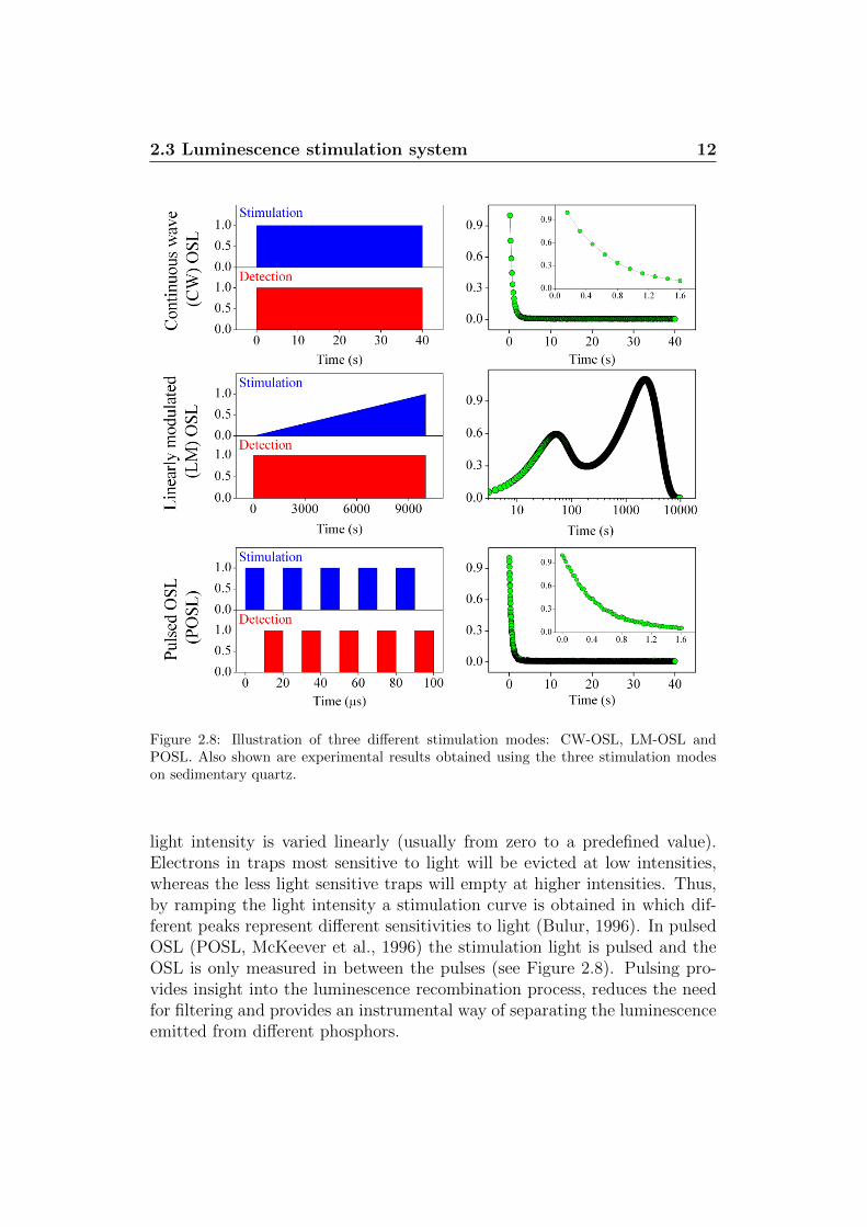
Conventionally, the samples are stimulated at constant light intensity(continuous wave CW-mode), which produces an exponentially decaying sig-nal as the electron traps are being depleted. However, the decay curves formost samples contain more than one component (i.e. traps with different op-tical cross-sections), and require several exponential functions to adequatelydescribe the data. In linearly modulated OSL (LM-OSL) the stimulation
2.3 Luminescence stimulation system 12
Figure 2.8: Illustration of three different stimulation modes: CW-OSL, LM-OSL andPOSL. Also shown are experimental results obtained using the three stimulation modeson sedimentary quartz.
light intensity is varied linearly (usually from zero to a predefined value).Electrons in traps most sensitive to light will be evicted at low intensities,whereas the less light sensitive traps will empty at higher intensities. Thus,by ramping the light intensity a stimulation curve is obtained in which dif-ferent peaks represent different sensitivities to light (Bulur, 1996). In pulsedOSL (POSL, McKeever et al., 1996) the stimulation light is pulsed and theOSL is only measured in between the pulses (see Figure 2.8). Pulsing pro-vides insight into the luminescence recombination process, reduces the needfor filtering and provides an instrumental way of separating the luminescenceemitted from different phosphors.
2.3 Luminescence stimulation system 13
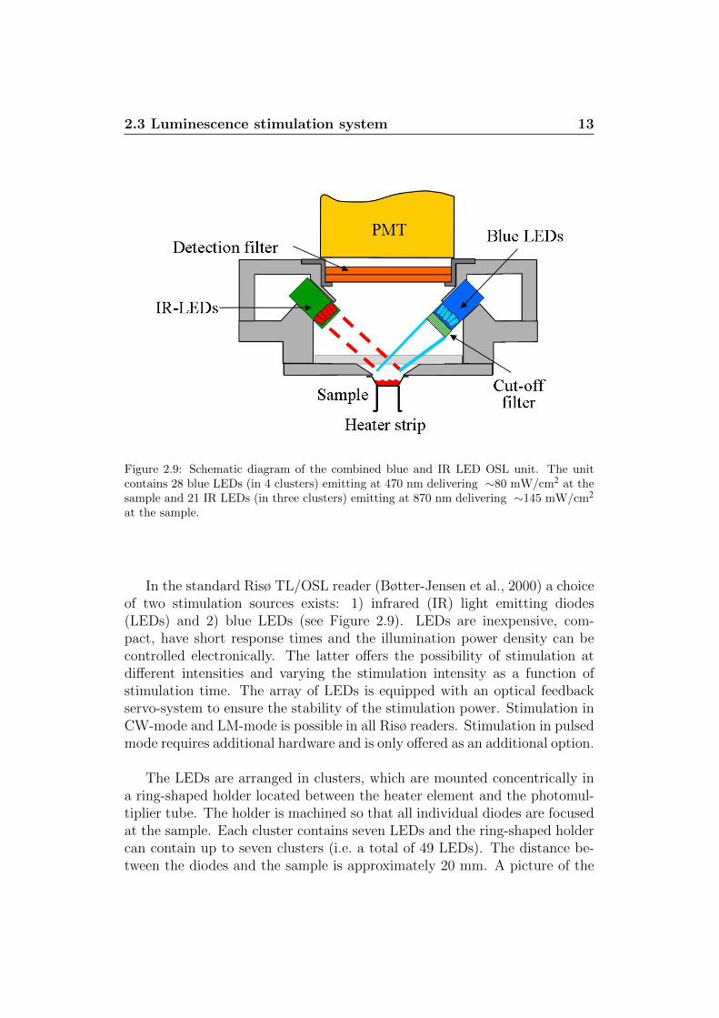
Figure 2.9: Schematic diagram of the combined blue and IR LED OSL unit. The unitcontains 28 blue LEDs (in 4 clusters) emitting at 470 nm delivering ∼80 mW/cm2 at thesample and 21 IR LEDs (in three clusters) emitting at 870 nm delivering ∼145 mW/cm2
at the sample.
In the standard Risø TL/OSL reader (Bøtter-Jensen et al., 2000) a choiceof two stimulation sources exists: 1) infrared (IR) light emitting diodes(LEDs) and 2) blue LEDs (see Figure 2.9). LEDs are inexpensive, com-pact, have short response times and the illumination power density can becontrolled electronically. The latter offers the possibility of stimulation atdifferent intensities and varying the stimulation intensity as a function ofstimulation time. The array of LEDs is equipped with an optical feedbackservo-system to ensure the stability of the stimulation power. Stimulation inCW-mode and LM-mode is possible in all Risø readers. Stimulation in pulsedmode requires additional hardware and is only offered as an additional option.
The LEDs are arranged in clusters, which are mounted concentrically ina ring-shaped holder located between the heater element and the photomul-tiplier tube. The holder is machined so that all individual diodes are focusedat the sample. Each cluster contains seven LEDs and the ring-shaped holdercan contain up to seven clusters (i.e. a total of 49 LEDs). The distance be-tween the diodes and the sample is approximately 20 mm. A picture of the
2.3 Luminescence stimulation system 14
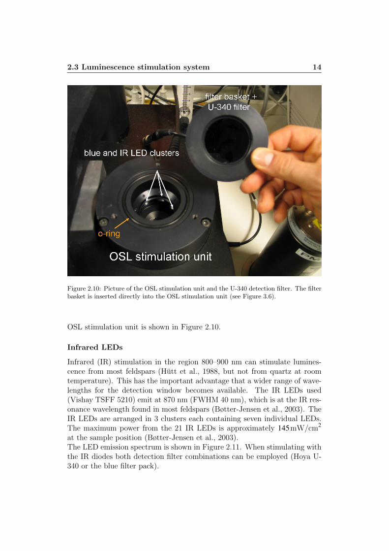
Figure 2.10: Picture of the OSL stimulation unit and the U-340 detection filter. The filterbasket is inserted directly into the OSL stimulation unit (see Figure 3.6).
OSL stimulation unit is shown in Figure 2.10.
Infrared LEDs
Infrared (IR) stimulation in the region 800–900 nm can stimulate lumines-cence from most feldspars (Hutt et al., 1988, but not from quartz at roomtemperature). This has the important advantage that a wider range of wave-lengths for the detection window becomes available. The IR LEDs used(Vishay TSFF 5210) emit at 870 nm (FWHM 40 nm), which is at the IR res-onance wavelength found in most feldspars (Bøtter-Jensen et al., 2003). TheIR LEDs are arranged in 3 clusters each containing seven individual LEDs.The maximum power from the 21 IR LEDs is approximately 145mW/cm2
at the sample position (Bøtter-Jensen et al., 2003).The LED emission spectrum is shown in Figure 2.11. When stimulating withthe IR diodes both detection filter combinations can be employed (Hoya U-340 or the blue filter pack).
2.3 Luminescence stimulation system 15
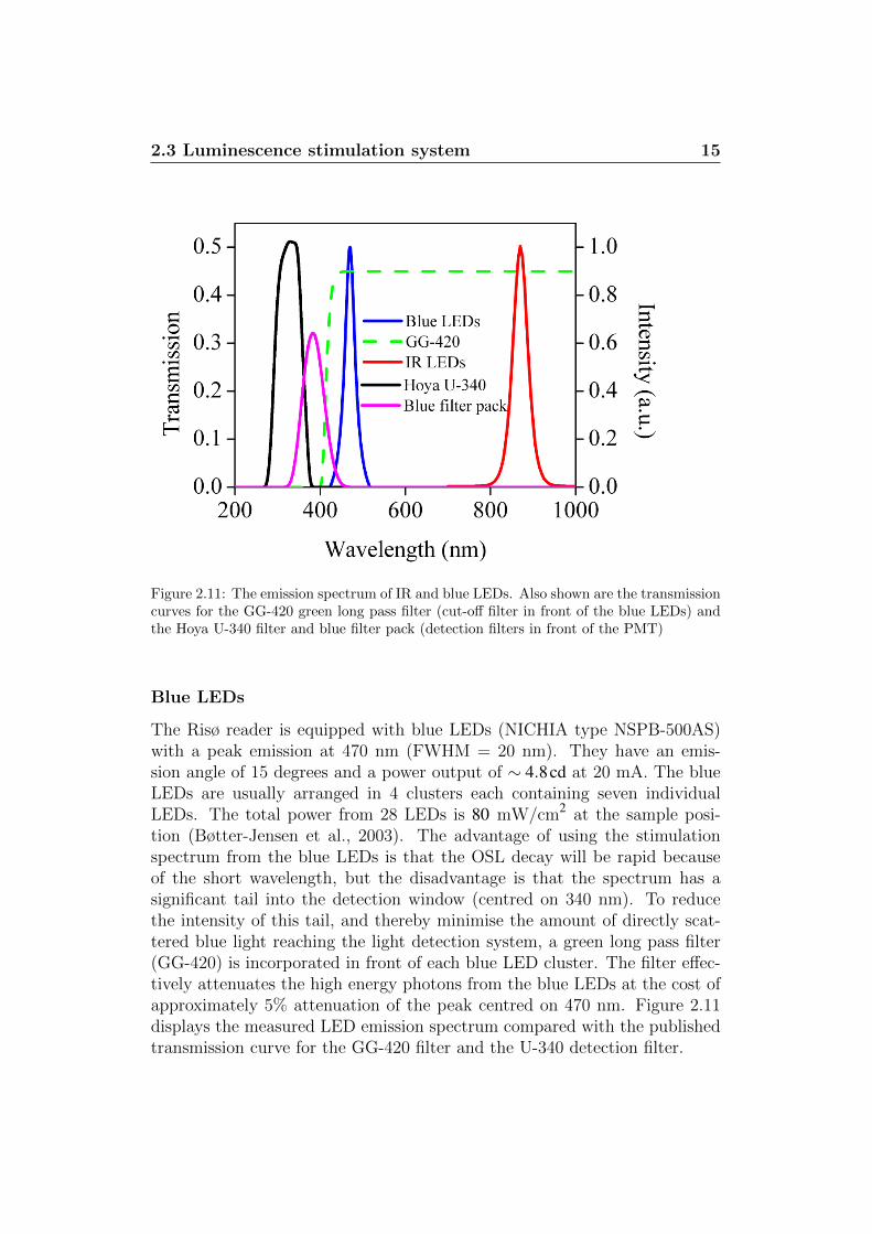
Figure 2.11: The emission spectrum of IR and blue LEDs. Also shown are the transmissioncurves for the GG-420 green long pass filter (cut-off filter in front of the blue LEDs) andthe Hoya U-340 filter and blue filter pack (detection filters in front of the PMT)
Blue LEDs
The Risø reader is equipped with blue LEDs (NICHIA type NSPB-500AS)with a peak emission at 470 nm (FWHM = 20 nm). They have an emis-sion angle of 15 degrees and a power output of ∼ 4.8cd at 20 mA. The blueLEDs are usually arranged in 4 clusters each containing seven individualLEDs. The total power from 28 LEDs is 80 mW/cm2 at the sample posi-tion (Bøtter-Jensen et al., 2003). The advantage of using the stimulationspectrum from the blue LEDs is that the OSL decay will be rapid becauseof the short wavelength, but the disadvantage is that the spectrum has asignificant tail into the detection window (centred on 340 nm). To reducethe intensity of this tail, and thereby minimise the amount of directly scat-tered blue light reaching the light detection system, a green long pass filter(GG-420) is incorporated in front of each blue LED cluster. The filter effec-tively attenuates the high energy photons from the blue LEDs at the cost ofapproximately 5% attenuation of the peak centred on 470 nm. Figure 2.11displays the measured LED emission spectrum compared with the publishedtransmission curve for the GG-420 filter and the U-340 detection filter.
2.3 Luminescence stimulation system 16
When stimulating with the blue LEDs only the U-340 detection filter can beused. SWITCHING ON THE BLUE LED’S WITH THE BLUE FILTERPACK IN PLACE WILL SERIOUSLY DAMAGE THE PMT.
Cross-talk
On a 48-sample carousel the distance between the centres of adjacent samplepositions is 17 mm. The consequence of this close spacing is that opticalstimulation of one sample may affect adjacent samples. This phenomenonis referred to as optical cross-talk (or cross-bleaching). In the following theoptical cross-talk is expressed as a percentage of the equivalent stimulationtime on the adjacent sample. Bray et al. (2002) measured the optical cross-talk using an array of blue LEDs delivering 18mW/cm2 to the sample andestimated it to be 0.014%. Bøtter-Jensen et al. (2000) measured the opticalcross-talk on a similar instrument to be 0.006% using an array of blue LEDsdelivering 28mW/cm2 to the sample. Although this cross-talk can be sig-nificant in highly sensitive samples, the effects can usually be disregarded ifcare is taken with the measurement sequence design.
2.3.3 Calibration LED
A weak reference light source (known as the blue “calibration LED”) is incor-porated in the reader and is used for routine check of the detection system. Asingle blue (470 nm) LED is mounted into a temperature stabilised (±0.5◦C)aluminium housing to provide a stable light output. A thin fibre guides theemitted LED light to the top of the heater unit where it points through ahole in the bottom part of either the TL flange or the OSL stimulation unit3.The reference light (barely visible to the naked eye) thus passes through theinterface quartz glass and the detection filter pack before reaching the cath-ode of the photomultiplier tube. The reference LED source serves two majorpurposes:
1. checking that the correct detection filter is placed in front of the PMtube before starting a sequence
2. long term stability control of the detection system where blue trans-mission filters are used (e.g. in TL mode)
When using blue light stimulation a U-340 detection filter is normally used.The U-340 does not pass blue light. If the U-340 filter is not inserted andthe powerful blue stimulation light by accident is switched on, this will cause
3This hole must always be oriented towards the middle of the measurement chamber.
2.3 Luminescence stimulation system 17
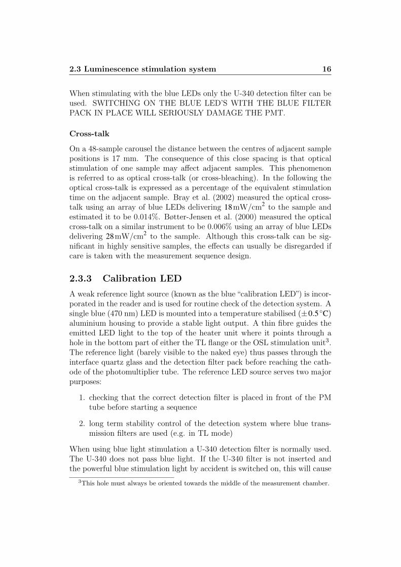
Figure 2.12: A weak blue LED is positioned on the main reader circuit board (in themetal cube). A light guide (black cable) transmits the light from this LED to the top ofthe heater unit. The purpose of this weak blue LED is to provide a check on the filtercombination in place and to provide a check on the sensitivity of the light detection systemwhen blue detection filters are used.
severe damage of the PM tube because of heavy illumination. Before begin-ning any measurement sequence the SEQUENCE EDITOR automaticallychecks that an appropriate detection filter is in place before the sequencecan actually start. First the normal PM dark counts are measured with thereference LED switched off and immediately after a measurement is madewith the reference LED switched on. If the second measurement increasesmore than 10% over the first measurement and the sequence contains bluelight stimulation (using the blue LED command) the sequence is not allowedto begin automatically and a warning will appear on screen. However, thissafety precaution will only be effective when the bottom flange (e.g. the TLflange or the OSL stimulation unit) is oriented correctly. It is possible tomount it with an off-set of 180◦C which would prevent the reference lightfrom reaching the PM tube regardless of the detection filter in place. Thus,it is recommended that whenever a blue light transmitting detection filtercombination is used then the blue LEDs are manually disabled. This can bedone using the switch at the back of the Controller (see Figure 7.1 page 61).
In TL mode it is common to use blue detection filters. Here the blue refer-ence LED source can be used for long term testing of the day-to-day stabilityof the PM tube or whether the detection filters or the interface quartz filter
2.4 Irradiation sources 18
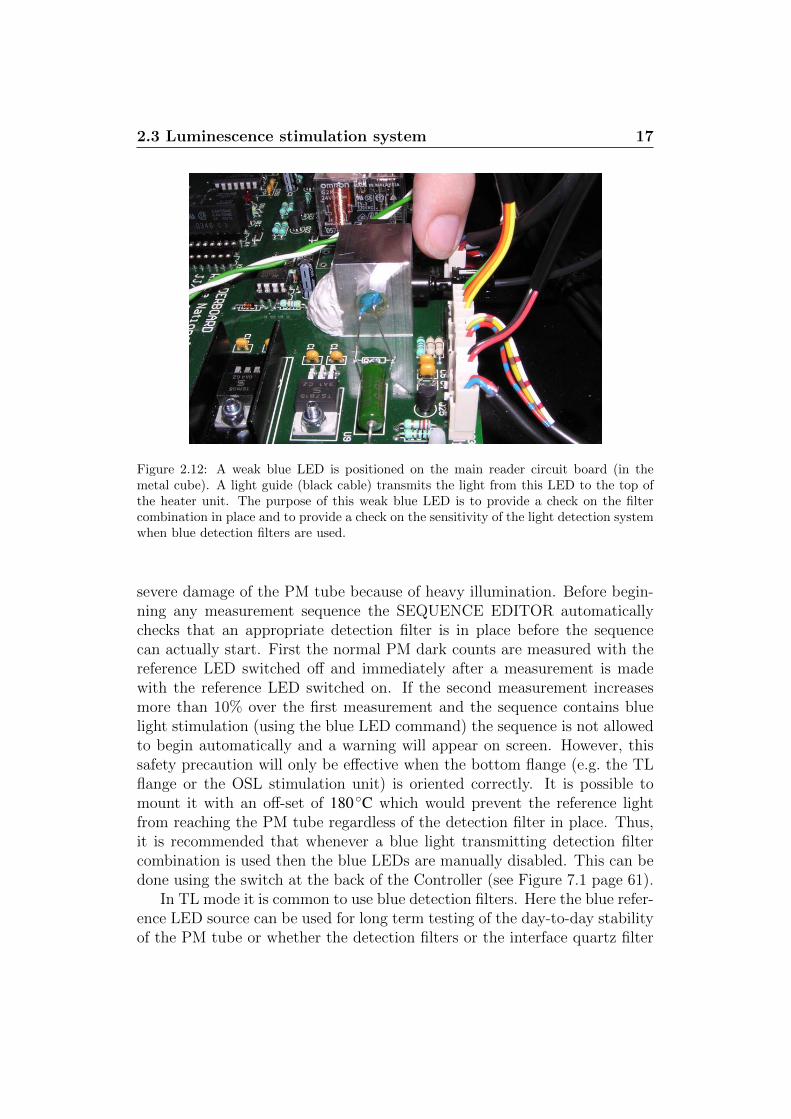
Figure 2.13: Picture of the TL flange. A hole has been drilled in the bottom of both theTL and OSL flanges. This hole allows the passage of a weak blue light flux (from the bluecalibration LED). The flange must be positioned in such a way that it is pointing towardsthe middle of the measurement chamber. a) Seen from above b) seen from below
have been contaminated (e.g. from silicone or moisture evaporated from thesamples during heating).
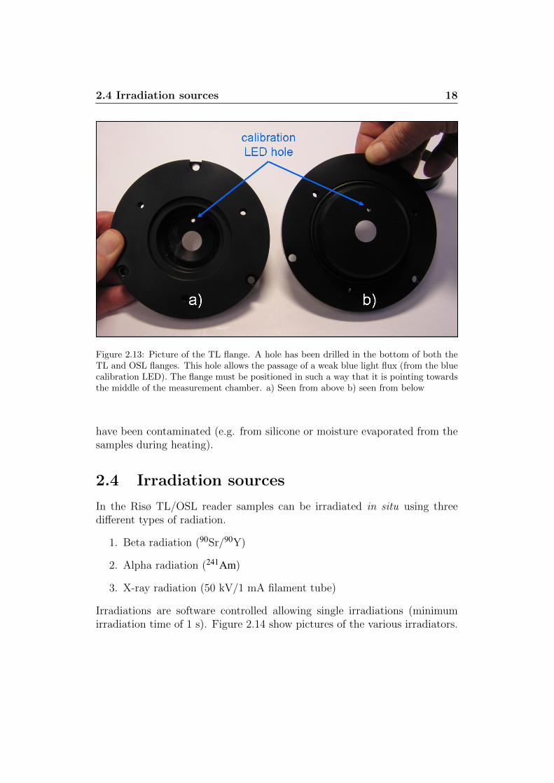
2.4 Irradiation sources
In the Risø TL/OSL reader samples can be irradiated in situ using threedifferent types of radiation.
1. Beta radiation (90Sr/90Y)
2. Alpha radiation (241Am)
3. X-ray radiation (50 kV/1 mA filament tube)
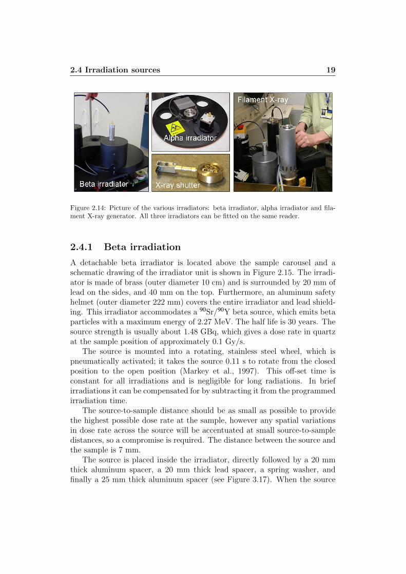
Irradiations are software controlled allowing single irradiations (minimumirradiation time of 1 s). Figure 2.14 show pictures of the various irradiators.
2.4 Irradiation sources 19
Figure 2.14: Picture of the various irradiators: beta irradiator, alpha irradiator and fila-ment X-ray generator. All three irradiators can be fitted on the same reader.
2.4.1 Beta irradiation
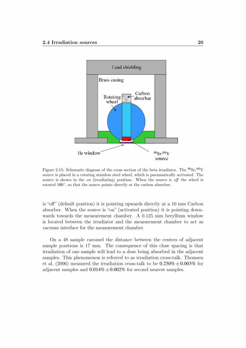
A detachable beta irradiator is located above the sample carousel and aschematic drawing of the irradiator unit is shown in Figure 2.15. The irradi-ator is made of brass (outer diameter 10 cm) and is surrounded by 20 mm oflead on the sides, and 40 mm on the top. Furthermore, an aluminum safetyhelmet (outer diameter 222 mm) covers the entire irradiator and lead shield-ing. This irradiator accommodates a 90Sr/90Y beta source, which emits betaparticles with a maximum energy of 2.27 MeV. The half life is 30 years. Thesource strength is usually about 1.48 GBq, which gives a dose rate in quartzat the sample position of approximately 0.1 Gy/s.
The source is mounted into a rotating, stainless steel wheel, which ispneumatically activated; it takes the source 0.11 s to rotate from the closedposition to the open position (Markey et al., 1997). This off-set time isconstant for all irradiations and is negligible for long radiations. In briefirradiations it can be compensated for by subtracting it from the programmedirradiation time.
The source-to-sample distance should be as small as possible to providethe highest possible dose rate at the sample, however any spatial variationsin dose rate across the source will be accentuated at small source-to-sampledistances, so a compromise is required. The distance between the source andthe sample is 7 mm.
The source is placed inside the irradiator, directly followed by a 20 mmthick aluminum spacer, a 20 mm thick lead spacer, a spring washer, andfinally a 25 mm thick aluminum spacer (see Figure 3.17). When the source
2.4 Irradiation sources 20
Figure 2.15: Schematic diagram of the cross section of the beta irradiator. The 90Sr/90Ysource is placed in a rotating stainless steel wheel, which is pneumatically activated. Thesource is shown in the on (irradiating) position. When the source is off the wheel isrotated 180 ◦, so that the source points directly at the carbon absorber.
is “off” (default position) it is pointing upwards directly at a 10 mm Carbonabsorber. When the source is “on” (activated position) it is pointing down-wards towards the measurement chamber. A 0.125 mm beryllium windowis located between the irradiator and the measurement chamber to act asvacuum interface for the measurement chamber.
On a 48 sample carousel the distance between the centres of adjacentsample positions is 17 mm. The consequence of this close spacing is thatirradiation of one sample will lead to a dose being absorbed in the adjacentsamples. This phenomenon is referred to as irradiation cross-talk. Thomsenet al. (2006) measured the irradiation cross-talk to be 0.250%± 0.003% foradjacent samples and 0.014%±0.002% for second nearest samples.
2.4 Irradiation sources 21
2.4.2 External dose rates
External dose rate originates entirely from bremsstrahlung due to interactionwith beta particles in surrounding materials. All dose rates reported belowwere measured using an Automess Scintomate 6134A, which is a calibratedplastic scintillation detector, specifically intended for measuring dose ratesfrom photons down to 40 keV. The measurements were carried out in a roomwith a background dose rate of ∼ 0.15µSv/hr.
• When the source is not activated the dose rate at a distance of 1 mfrom the front surface of the Risø reader is < 0.4µSv/hr. When thesource is activated the dose rate is < 0.5µSv/hr.
• The dose rate directly on the surface of the irradiator is < 5µSv/hrboth when the source is activated and not activated.
• The maximum dose rate directly on the side of the reader (the sideclosest to the irradiator) increases from 5µSv/h to < 100µSv/h whenthe source is open. It is not possible to be situated close to this sideof the reader (the 100µSv/h drops to 17µSv/h even 10 cm away fromthe surface), but nevertheless this dose rate can readily be reducedto << 1µSv/h by placing one cm of lead shielding right under theirradiator along this side of the reader. However, we do not regard itas necessary to shield either the front or the other sides of the reader.We also recommend that the reader is positioned in such a way thatthe space underneath it is inaccessible (the dose rate underneath awooden table with a thickness of 25 mm is < 3µSv/h when the sourceis inactivated and < 40µSv/h when the source is activated).
The lid is both electronically and mechanically inter-locked so it cannotbe opened while the source is energized. If the lid is forced open software andhardware interlocks will de-energize the irradiator and returning the sourceto its default safe position. An external indicator positioned next to theirradiator glows red when the source is activated and green when the sourceis de-energized.
2.4.3 Alpha irradiation
The alpha irradiator normally accommodates a 10.7 MBq (290 mCi) 241Amfoil source, which is a mixed alpha/gamma emitter. The dominating alphaenergy is 5.49 MeV (85.1%) and the dominating gamma energy is 59 keV.The source is mounted behind a pneumatically controlled shutter. The alphairradiator option is integrated with the system lid and a sealed shaft allows
2.4 Irradiation sources 22
operation of the irradiator under vacuum. The dose rate in quartz at thesample position is approximately 45 mGy/s.
2.4.4 X-ray irradiation
The X-ray irradiator is a filament type X-ray: Varian VF-50J X-ray tube(50 kV, 1 mA, 50 W) with tungsten target and a 4-50 kV DC Spellmanhigh voltage power supply (Andersen et al., 2003). The tube is mounted ona 35 mm long brass collimator (internal diameter 10 mm) with a 50µm Alend window at the exit. A 7 mm thick mechanical shutter made of stainlesssteel is positioned within the length of the collimator to prevent the samplefrom being irradiated until the X-ray output has stabilized. At the end of anirradiation the shutter is closed before the X-ray is switched off. It takes theshutter 62 ms to open and 145 ms to close. Thus, the actual irradiation timeis about 80 ms longer than the programmed time. The distance from theface of the X-ray tube to the sample is 35.5 mm, and the average dose rateat 50 kV and 1 mA (maximum power) to quartz grains mounted on stainlesssteel discs is approximately 2 Gy/s.
Spooner and Allsop (2000) examined the spatial variation of dose-ratefrom a 90Sr/90Y beta source and found that the dose rate could vary by15% across a 10 mm sample area for a source/sample distance of 15 mm.Others have reported higher spatial dose rate variations for their sources(Ballarini et al., 2006). The spatial variation of dose-rate for the filamentX-ray is less than 1%. For the filament X-ray the irradiation cross-talk is0.0012%±0.0001% for the adjacent samples and less than 10−4% for secondnearest samples.
There is an excellent linearity between tube current (as set by the user)and dose rate. It has a dynamic dose rate range between 10 mGy/s and2 Gy/s at 50 kV and 2-30 mGy/s at 10 kV) when mounted on a standardOSL/TL reader. The short-term stability is better than about 0.2% (An-dersen et al., 2003). The X-ray irradiator incorporates an enhanced securitycontrol and fail-safe system to meet the individual “regulations for operation”as issued by the different local governments of different countries

3
Installation of the RisøTL/OSL reader
This section details how to install the Risø TL/OSL reader.
3.1 Components
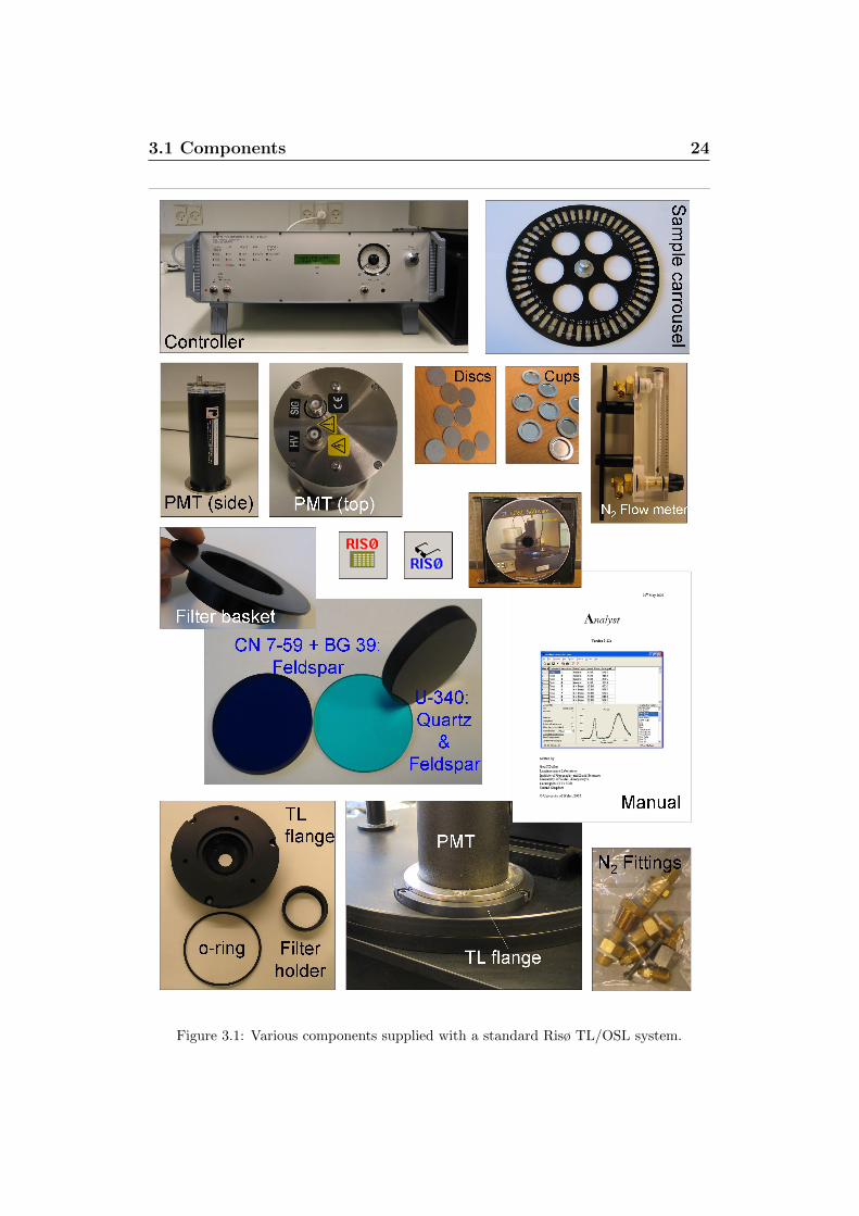
Below is a list of the components supplied with a standard Risø TL/OSLsystem (see also Figure 3.1).
1. The Reader (40 cm × 55 cm × 55 cm)
2. The Controller (50 cm × 55 cm × 20 cm)
3. PM tube
4. Nitrogen tubing
5. Nitrogen fittings
6. Flow meter
7. Tools for loading the source
8. Manuals (e.g. Analyst, Sequence Editor)
9. Risø software (CD). Includes programmes required for running the sys-tem, analysis software, electronic versions of all manuals, short moviesshowing how to load the beta source, how to connect the Nitrogensupply etc.
10. Two sample carrousels
3.1 Components 24
Figure 3.1: Various components supplied with a standard Risø TL/OSL system.

3.2 Installing the hardware 25
• A 48 position sample carrousel for cups (planchettes)
• A 48 position sample carrousel for discs
11. 100 stainless steel cups (to be used with the sample carrousel labelled“CUPS”)
12. 100 stainless steel discs (to be used with the sample carrousel labelled“DISCS”)
13. Filter basket with 7.5 mm Hoya U-340 filter (already placed in the OSLstimulation unit when the system is received by the end-user)
14. Filters: Corning 7-59 (4 mm) or BG3 (3 mm) and Schott BG-39 (2mm)
15. Extra filter basket
16. Flange for TL measurements including a special filter basket to beused with the TL flange. If no OSL measurements are to be madeit is advantageous to remove the OSL stimulation unit and replace itwith this TL flange because of the improved detection geometry (thePMT is situated closer to the sample when the OSL stimulation unitis replaced by the TL flange)
17. OSL test cable. This test cable can be used to monitor the currentthrough the OSL stimulation unit (see Figure 7.1)
18. Circlip pliers. These pliers are only used when the beta source has tobe loaded/unloaded (see section 3.5)
3.2 Installing the hardware
3.2.1 Unpacking
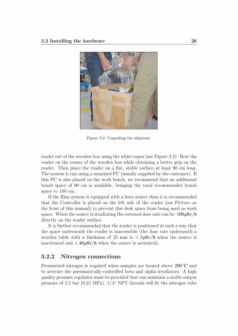
The Risø TL/OSL reader is shipped in a durable wooden box (59cm×66cm×80cm). Please, keep this box in case you need to move the reader to a differentlocation or have it sent back to Risø for repair.The beta irradiator is surrounded by lead shielding which again is surroundedby an aluminium safety helmet (outer diameter 222 mm). The lead shieldingweighs about 20 kg, so before lifting the reader out of the box it is advisableto remove this shielding. The aluminium helmet is held in place by twoscrews.The reader it self weighs 80-90 kg so it is advisable that two persons lift the
3.2 Installing the hardware 26
Figure 3.2: Unpacking the shipment.
reader out of the wooden box using the white ropes (see Figure 3.2). Rest thereader on the corner of the wooden box while obtaining a better grip on thereader. Then place the reader on a flat, stable surface at least 90 cm long.The system is run using a standard PC (usually supplied by the customer). Ifthis PC is also placed on the work bench, we recommend that an additionalbench space of 90 cm is available, bringing the total recommended benchspace to 180 cm.
If the Risø system is equipped with a beta source then it is recommendedthat the Controller is placed on the left side of the reader (see Picture onthe front of this manual) to prevent this desk space from being used as workspace. When the source is irradiating the external dose rate can be 100µSv/hdirectly on the reader surface.
It is further recommended that the reader is positioned in such a way thatthe space underneath the reader is inaccessible (the dose rate underneath awooden table with a thickness of 25 mm is < 3µSv/h when the source isinactivated and < 40µSv/h when the source is activated).
3.2.2 Nitrogen connections
Pressurized nitrogen is required when samples are heated above 200◦C andto activate the pneumatically-controlled beta and alpha irradiators. A highquality pressure regulator must be provided that can maintain a stable outputpressure of 2.5 bar (0.25 MPa). 1/4” NPT threads will fit the nitrogen tube
3.2 Installing the hardware 27
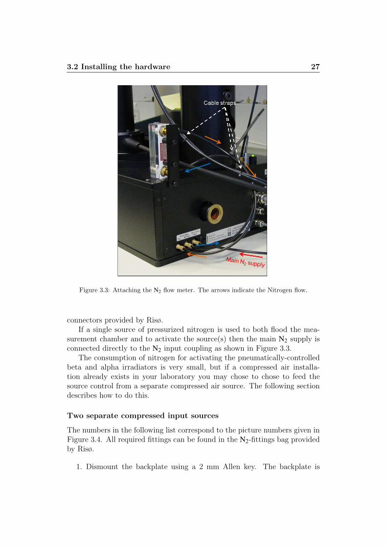
Figure 3.3: Attaching the N2 flow meter. The arrows indicate the Nitrogen flow.
connectors provided by Risø.If a single source of pressurized nitrogen is used to both flood the mea-
surement chamber and to activate the source(s) then the main N2 supply isconnected directly to the N2 input coupling as shown in Figure 3.3.
The consumption of nitrogen for activating the pneumatically-controlledbeta and alpha irradiators is very small, but if a compressed air installa-tion already exists in your laboratory you may chose to chose to feed thesource control from a separate compressed air source. The following sectiondescribes how to do this.
Two separate compressed input sources
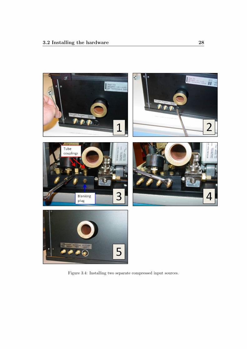
The numbers in the following list correspond to the picture numbers given inFigure 3.4. All required fittings can be found in the N2-fittings bag providedby Risø.
1. Dismount the backplate using a 2 mm Allen key. The backplate is
3.2 Installing the hardware 28
Figure 3.4: Installing two separate compressed input sources.
3.2 Installing the hardware 29
being held in place by 5 screws.
2. Remove the cap.
3. Dismount the two tube couplings on the top and the blanking plug onthe side.
4. Mount two blanking plugs on the top and a tube coupling on the sideof the manifold using a 7 mm key.Remount the backplate.
5. Connect the compressed air to the N2 input (the third tube couplingfrom the left).Connect the tube from the N2 main supply to the just mounted tubecoupling (the fourth tube coupling from the left).Mount the enclosed label over the old label.
3.2.3 Attaching the flow meter
The flow meter and its position on the reader is shown in Figure 3.3. Attachthe N2 tubes as shown. The arrows indicate the Nitrogen flow. Also shownis advantageous places to position cable straps. Using cable straps in thisway reduces the risk of getting the Nitrogen tubes caught between the lidand the reader while opening and closing the lid.
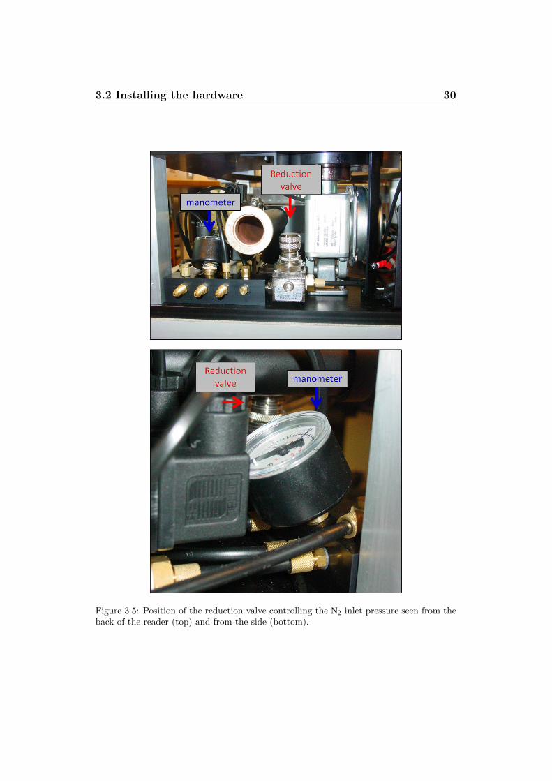
The 2.5 bar N2 input pressure is reduced to 0.8 bar to reduce the riskof discs being blown off the heater element when the measurement chamberis flooded with N2. However, if a different flow pressure is required it canbe adjusted manually using the reduction valve located on the pressured airmanifold (see Figure 3.5). The inlet pressure can be read off the manometerlocated next to the reduction valve. To gain access to this reduction valveeither remove the backplate as shown in Figure 3.4 or simply remove thecover.
3.2.4 Mounting the PMT
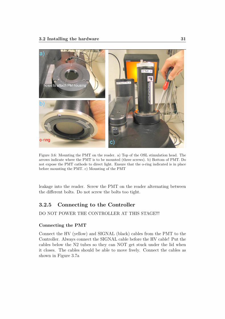
The PMT is mounted directly on top of the OSL stimulation unit (see Figure3.6c). The PMT is a very sensitive device that ought to be handled with greatcare. Please avoid exposing the photocathode to direct light (even whenthe PMT is not powered). Remember to insert the detection filter beforemounting the PMT. Ensure that the o-ring below the filter basket is in placebefore inserting the filter basket (see Figure 2.10). Ensure that the o-ringlocated underneath the PMT is in place. This is important to prevent light
3.2 Installing the hardware 30
Figure 3.5: Position of the reduction valve controlling the N2 inlet pressure seen from theback of the reader (top) and from the side (bottom).
3.2 Installing the hardware 31
Figure 3.6: Mounting the PMT on the reader. a) Top of the OSL stimulation head. Thearrows indicate where the PMT is to be mounted (three screws). b) Bottom of PMT. Donot expose the PMT cathode to direct light. Ensure that the o-ring indicated is in placebefore mounting the PMT. c) Mounting of the PMT
leakage into the reader. Screw the PMT on the reader alternating betweenthe different bolts. Do not screw the bolts too tight.
3.2.5 Connecting to the Controller
DO NOT POWER THE CONTROLLER AT THIS STAGE!!!
Connecting the PMT
Connect the HV (yellow) and SIGNAL (black) cables from the PMT to theController. Always connect the SIGNAL cable before the HV cable! Put thecables below the N2 tubes so they can NOT get stuck under the lid whenit closes. The cables should be able to move freely. Connect the cables asshown in Figure 3.7a
3.2 Installing the hardware 32
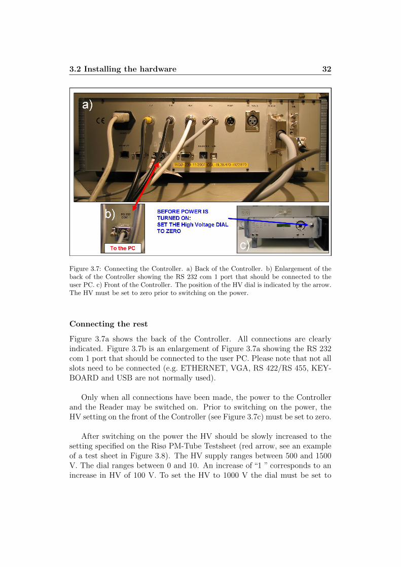
Figure 3.7: Connecting the Controller. a) Back of the Controller. b) Enlargement of theback of the Controller showing the RS 232 com 1 port that should be connected to theuser PC. c) Front of the Controller. The position of the HV dial is indicated by the arrow.The HV must be set to zero prior to switching on the power.
Connecting the rest
Figure 3.7a shows the back of the Controller. All connections are clearlyindicated. Figure 3.7b is an enlargement of Figure 3.7a showing the RS 232com 1 port that should be connected to the user PC. Please note that not allslots need to be connected (e.g. ETHERNET, VGA, RS 422/RS 455, KEY-BOARD and USB are not normally used).
Only when all connections have been made, the power to the Controllerand the Reader may be switched on. Prior to switching on the power, theHV setting on the front of the Controller (see Figure 3.7c) must be set to zero.
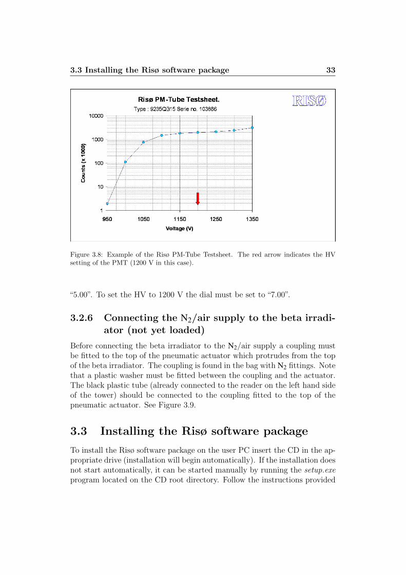
After switching on the power the HV should be slowly increased to thesetting specified on the Risø PM-Tube Testsheet (red arrow, see an exampleof a test sheet in Figure 3.8). The HV supply ranges between 500 and 1500V. The dial ranges between 0 and 10. An increase of “1 ” corresponds to anincrease in HV of 100 V. To set the HV to 1000 V the dial must be set to
3.3 Installing the Risø software package 33
Figure 3.8: Example of the Risø PM-Tube Testsheet. The red arrow indicates the HVsetting of the PMT (1200 V in this case).
“5.00”. To set the HV to 1200 V the dial must be set to “7.00”.
3.2.6 Connecting the N2/air supply to the beta irradi-ator (not yet loaded)
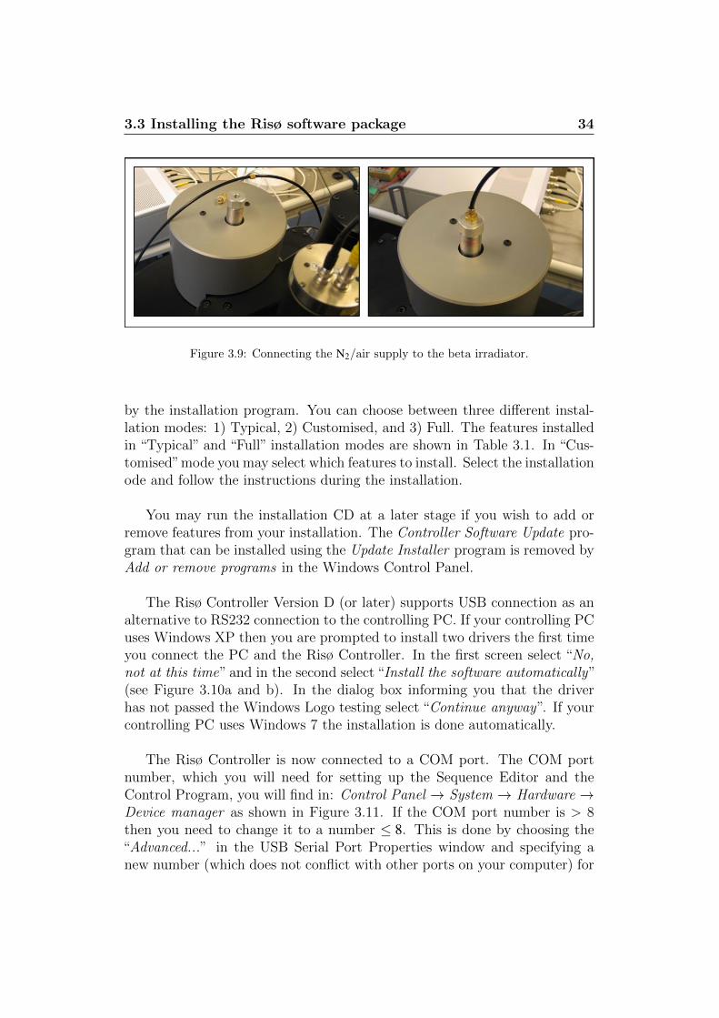
Before connecting the beta irradiator to the N2/air supply a coupling mustbe fitted to the top of the pneumatic actuator which protrudes from the topof the beta irradiator. The coupling is found in the bag with N2 fittings. Notethat a plastic washer must be fitted between the coupling and the actuator.The black plastic tube (already connected to the reader on the left hand sideof the tower) should be connected to the coupling fitted to the top of thepneumatic actuator. See Figure 3.9.
3.3 Installing the Risø software package
To install the Risø software package on the user PC insert the CD in the ap-propriate drive (installation will begin automatically). If the installation doesnot start automatically, it can be started manually by running the setup.exeprogram located on the CD root directory. Follow the instructions provided
3.3 Installing the Risø software package 34
Figure 3.9: Connecting the N2/air supply to the beta irradiator.
by the installation program. You can choose between three different instal-lation modes: 1) Typical, 2) Customised, and 3) Full. The features installedin “Typical” and “Full” installation modes are shown in Table 3.1. In “Cus-tomised”mode you may select which features to install. Select the installationode and follow the instructions during the installation.
You may run the installation CD at a later stage if you wish to add orremove features from your installation. The Controller Software Update pro-gram that can be installed using the Update Installer program is removed byAdd or remove programs in the Windows Control Panel.
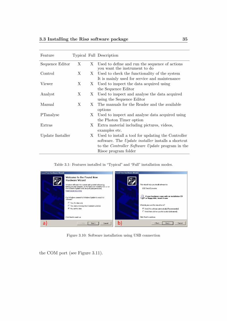
The Risø Controller Version D (or later) supports USB connection as analternative to RS232 connection to the controlling PC. If your controlling PCuses Windows XP then you are prompted to install two drivers the first timeyou connect the PC and the Risø Controller. In the first screen select “No,not at this time” and in the second select “Install the software automatically”(see Figure 3.10a and b). In the dialog box informing you that the driverhas not passed the Windows Logo testing select “Continue anyway”. If yourcontrolling PC uses Windows 7 the installation is done automatically.
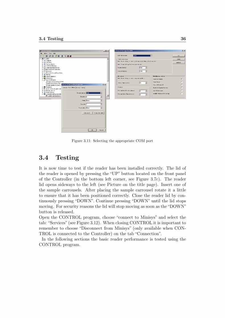
The Risø Controller is now connected to a COM port. The COM portnumber, which you will need for setting up the Sequence Editor and theControl Program, you will find in: Control Panel → System → Hardware →Device manager as shown in Figure 3.11. If the COM port number is > 8then you need to change it to a number ≤ 8. This is done by choosing the“Advanced...” in the USB Serial Port Properties window and specifying anew number (which does not conflict with other ports on your computer) for
3.3 Installing the Risø software package 35
Feature Typical Full Description
Sequence Editor X X Used to define and run the sequence of actionsyou want the instrument to do
Control X X Used to check the functionality of the systemIt is mainly used for service and maintenance
Viewer X X Used to inspect the data acquired usingthe Sequence Editor
Analyst X X Used to inspect and analyse the data acquiredusing the Sequence Editor
Manual X X The manuals for the Reader and the availableoptions
PTanalyse X Used to inspect and analyse data acquired usingthe Photon Timer option
Extras X Extra material including pictures, videos,examples etc.
Update Installer X Used to install a tool for updating the Controllersoftware. The Update installer installs a shortcutto the Controller Software Update program in theRisoe program folder
Table 3.1: Features installed in “Typical” and “Full” installation modes.
Figure 3.10: Software installation using USB connection
the COM port (see Figure 3.11).
3.4 Testing 36
Figure 3.11: Selecting the appropriate COM port
3.4 Testing
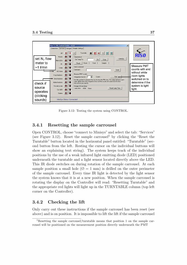
It is now time to test if the reader has been installed correctly. The lid ofthe reader is opened by pressing the “UP” button located on the front panelof the Controller (in the bottom left corner, see Figure 3.7c). The readerlid opens sideways to the left (see Picture on the title page). Insert one ofthe sample carrousels. After placing the sample carrousel rotate it a littleto ensure that it has been positioned correctly. Close the reader lid by con-tinuously pressing “DOWN”. Continue pressing “DOWN” until the lid stopsmoving. For security reasons the lid will stop moving as soon as the“DOWN”button is released.Open the CONTROL program, choose “connect to Minisys” and select thetab: “Services”(see Figure 3.12). When closing CONTROL it is important toremember to choose “Disconnect from Minisys” (only available when CON-TROL is connected to the Controller) on the tab “Connection”.
In the following sections the basic reader performance is tested using theCONTROL program.
3.4 Testing 37
Figure 3.12: Testing the system using CONTROL.
3.4.1 Resetting the sample carrousel
Open CONTROL, choose “connect to Minisys” and select the tab: “Services”(see Figure 3.12). Reset the sample carrousel1 by clicking the “Reset theTurntable” button located in the horizontal panel entitled: “Turntable” (sec-ond button from the left. Resting the cursor on the individual buttons willshow an explaining text string). The system keeps track of the individualpositions by the use of a weak infrared light emitting diode (LED) positionedunderneath the turntable and a light sensor located directly above the LED.This IR diode switches on during rotation of the sample carrousel. At eachsample position a small hole (Ø = 1 mm) is drilled on the outer perimeterof the sample carrousel. Every time IR light is detected by the light sensorthe system knows that it is at a new position. When the sample carrousel isrotating the display on the Controller will read: “Resetting Turntable” andthe appropriate red lights will light up in the TURNTABLE column (top leftcorner on the Controller).
3.4.2 Checking the lift
Only carry out these instructions if the sample carrousel has been reset (seeabove) and is on position. It is impossible to lift the lift if the sample carrousel
1Resetting the sample carrousel/turntable means that position 1 on the sample car-rousel will be positioned on the measurement position directly underneath the PMT
3.4 Testing 38
is not on position.Raise the lift by clicking the “Lift up” button (arrow up, vertical columnson the left of the screen). Monitor the lights on the front of the Controller.The “LIFT RUN” light is on during movement and the “LIFT UP” light ison when movement stops. Lower the lift by clicking the “Lift down” button(arrow down, vertical columns on the left of the screen). Monitor the lightson the front of the Controller. The “LIFT RUN” light is on during movementand the “LIFT DOWN” light is on when movement stops.
3.4.3 Checking the Blue LEDs
To check that the blue LEDs can be switched on, press the “Blue LEDs”button and open the lid. The light from the blue LEDs should be clearlyvisible by eye. Close the lid again and switch off the Blue LEDs.
3.4.4 Adjusting the N2 flow rate
To adjust the N2 flow rate, switch on the N2 flow (“N2 valve”) and adjustthe flow on the flow meter (see Figure 3.3) to 1 l/min using the black knob.Switch off the N2 flow.
3.4.5 Checking the beta irradiator
To check if the beta irradiator is operational click the“beta irradiator”button.A clicking sound should be clearly audible (the sound of the pneumaticallyactivated rotating stainless steel wheel).
3.4.6 Checking the alpha irradiator
To check if the alpha irradiator is operational click the “alpha irradiator”button. A clicking sound should be clearly audible (the sound of the pneu-matically activated shutter).
3.4.7 Measure PMT counts
This section is used to measure the counts detected by the PMT. On the leftthe time interval being integrated can be changed (default 1 s). Measure-ment is started by clicking “Start”. Whenever the PMT has been taken offthe reader (e.g. because of filter changing) the user ought to check if any lightleaks have been introduced into the system. This can be done by measuringthe PMT counts with and without the white room lights switched on. If

3.5 Loading the beta source 39
the counts increase when the room lights are switched on it means that alight leak has been introduced into the system - probably because an o-ringhas been forgotten or the PMT is not mounted properly. It is normal thatthe dark count will be slightly elevated immediately after mounting the PMT.
Close CONTROL by choosing “Disconnect from Minisys” (only availablewhen CONTROL is connected to the Controller) on the tab “Connection”.
3.5 Loading the beta source
This section describes the procedure of loading/unloading the 90Sr/90Y sourcein the Risø beta irradiator. Please read the instructions carefully and watchthe video showing how to load the source (C:\Risoe\Movies\Cable connec-tion.mpg) before attempting to unload/load the source.
Before beginning the procedure of unloading/loading the beta source,make sure that
a) an empty desk space of 60× 60 cm is available to handle the irradiatorduring unloading/loading
b) the following tools are kept within reach:
• Two hexagonal keys (Allen keys), 4 mm and 5 mm
• The circlip pliers (delivered with the Risø reader)
• The source handling rod (delivered with the source)
• 10 mm perspex/plexiglass plate and a vice to hold it. This plateis to be used as protection when the source is exposed
You should now be ready to begin the procedure of loading/unloading thebeta source. The source will be exposed in item 8 and 9.
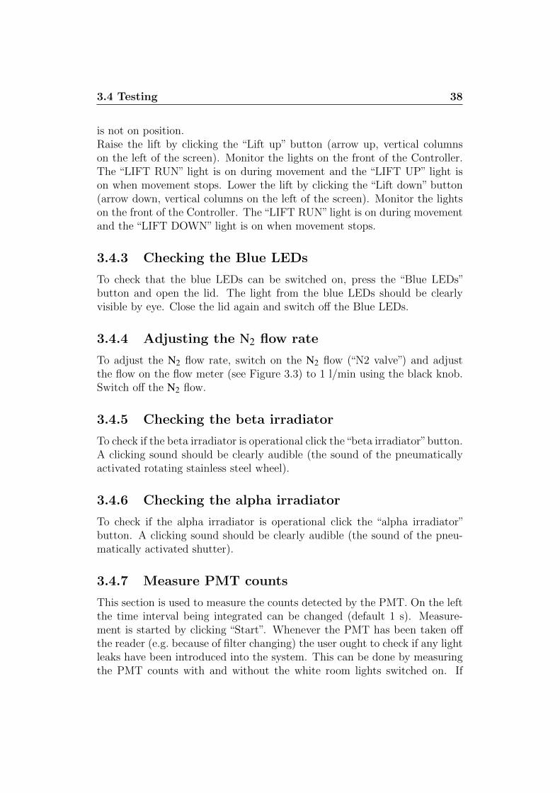
1. Remove the plastic air tube (Figure 3.13). If the irradiator module isfitted with an aluminium helmet (new models) remove it. Then removethe lid of the lead shielding
3.5 Loading the beta source 40
Figure 3.13: Removing the air tube.
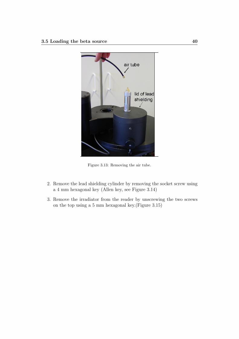
2. Remove the lead shielding cylinder by removing the socket screw usinga 4 mm hexagonal key (Allen key, see Figure 3.14)
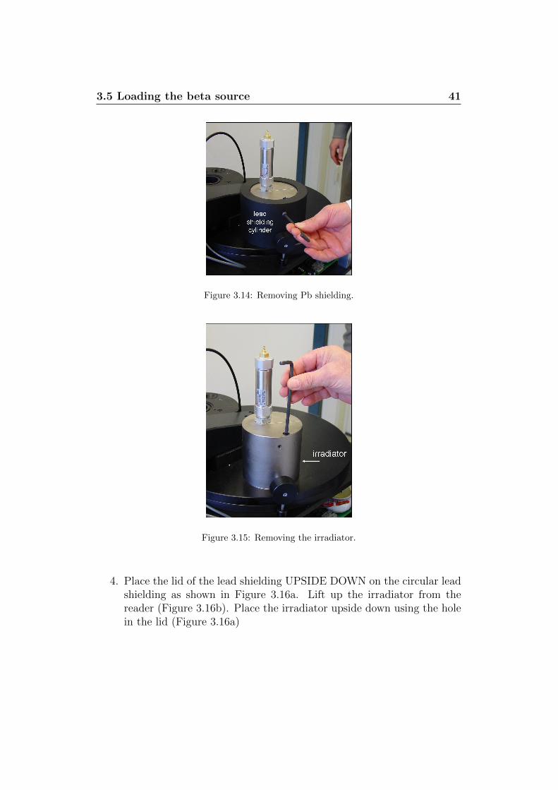
3. Remove the irradiator from the reader by unscrewing the two screwson the top using a 5 mm hexagonal key.(Figure 3.15)
3.5 Loading the beta source 41
Figure 3.14: Removing Pb shielding.
Figure 3.15: Removing the irradiator.
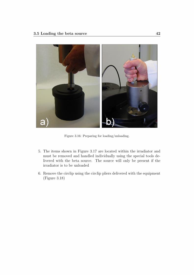
4. Place the lid of the lead shielding UPSIDE DOWN on the circular leadshielding as shown in Figure 3.16a. Lift up the irradiator from thereader (Figure 3.16b). Place the irradiator upside down using the holein the lid (Figure 3.16a)
3.5 Loading the beta source 42
Figure 3.16: Preparing for loading/unloading.
5. The items shown in Figure 3.17 are located within the irradiator andmust be removed and handled individually using the special tools de-livered with the beta source. The source will only be present if theirradiator is to be unloaded
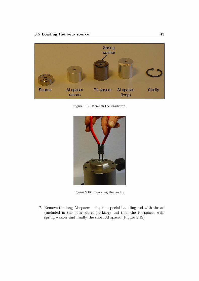
6. Remove the circlip using the circlip pliers delivered with the equipment(Figure 3.18)
3.5 Loading the beta source 43
Figure 3.17: Items in the irradiator.
Figure 3.18: Removing the circlip.
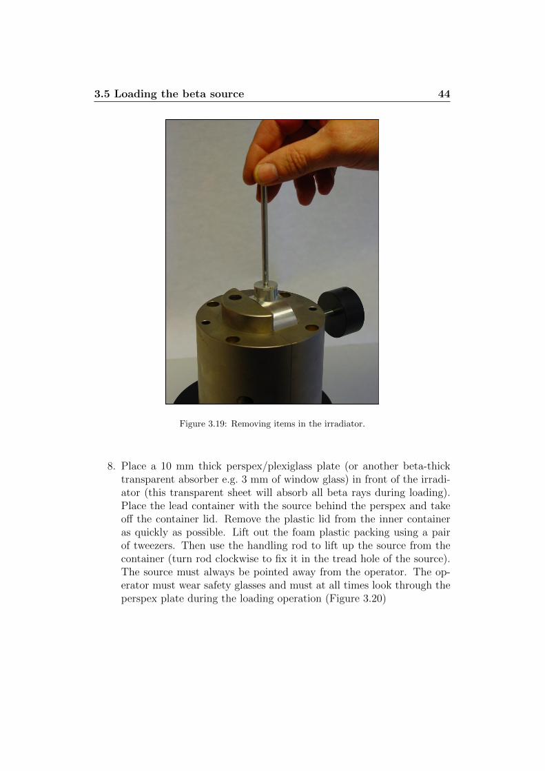
7. Remove the long Al spacer using the special handling rod with thread(included in the beta source packing) and then the Pb spacer withspring washer and finally the short Al spacer (Figure 3.19)
3.5 Loading the beta source 44
Figure 3.19: Removing items in the irradiator.
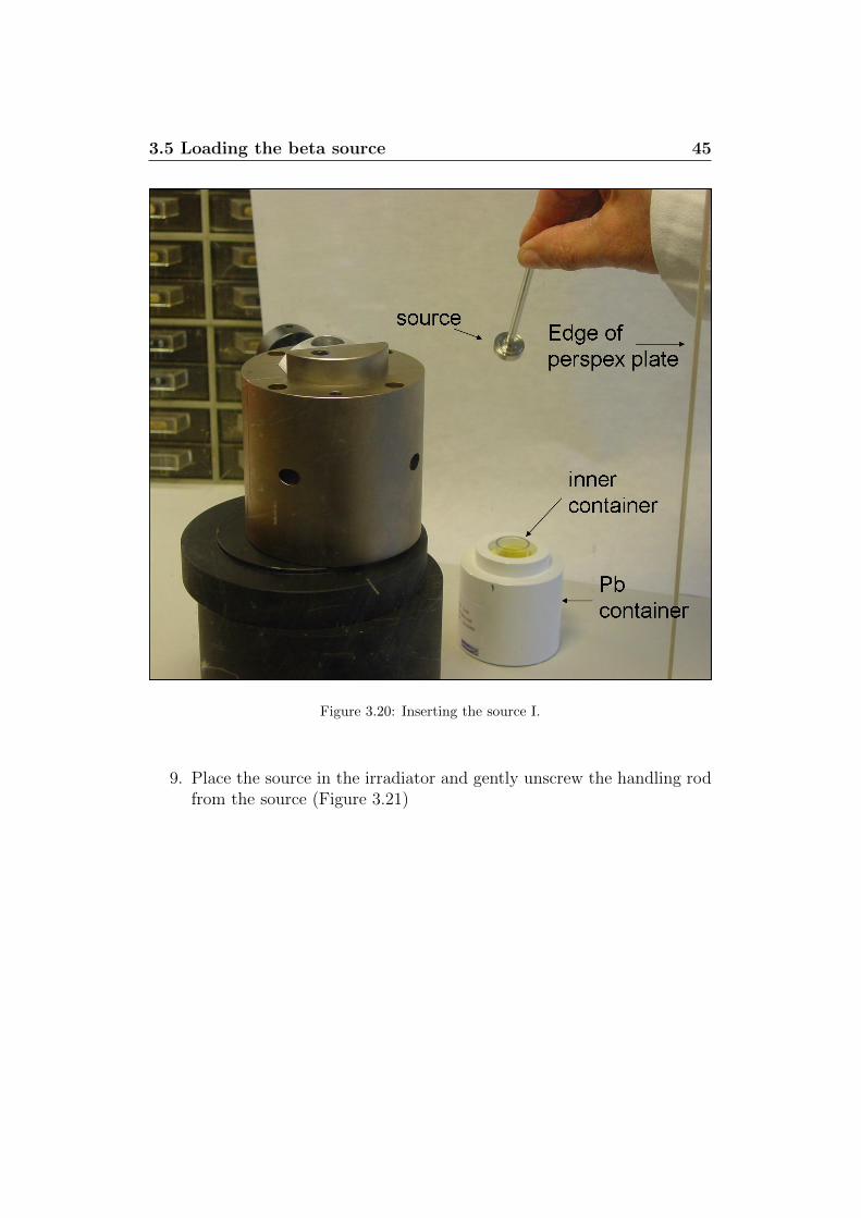
8. Place a 10 mm thick perspex/plexiglass plate (or another beta-thicktransparent absorber e.g. 3 mm of window glass) in front of the irradi-ator (this transparent sheet will absorb all beta rays during loading).Place the lead container with the source behind the perspex and takeoff the container lid. Remove the plastic lid from the inner containeras quickly as possible. Lift out the foam plastic packing using a pairof tweezers. Then use the handling rod to lift up the source from thecontainer (turn rod clockwise to fix it in the tread hole of the source).The source must always be pointed away from the operator. The op-erator must wear safety glasses and must at all times look through theperspex plate during the loading operation (Figure 3.20)
3.5 Loading the beta source 45
Figure 3.20: Inserting the source I.
9. Place the source in the irradiator and gently unscrew the handling rodfrom the source (Figure 3.21)
3.5 Loading the beta source 46
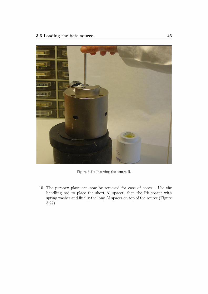
Figure 3.21: Inserting the source II.
10. The perspex plate can now be removed for ease of access. Use thehandling rod to place the short Al spacer, then the Pb spacer withspring washer and finally the long Al spacer on top of the source (Figure3.22)
3.5 Loading the beta source 47
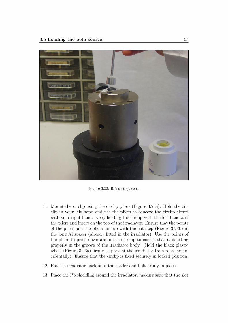
Figure 3.22: Reinsert spacers.
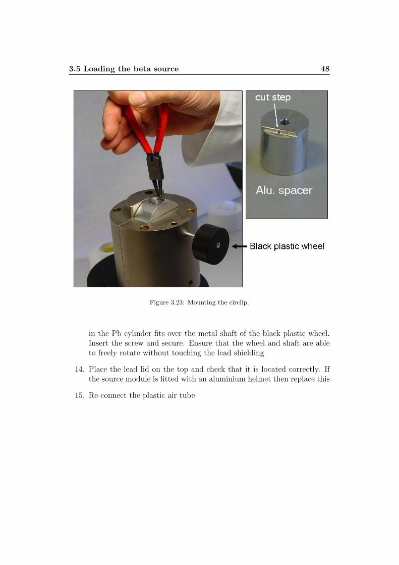
11. Mount the circlip using the circlip pliers (Figure 3.23a). Hold the cir-clip in your left hand and use the pliers to squeeze the circlip closedwith your right hand. Keep holding the circlip with the left hand andthe pliers and insert on the top of the irradiator. Ensure that the pointsof the pliers and the pliers line up with the cut step (Figure 3.23b) inthe long Al spacer (already fitted in the irradiator). Use the points ofthe pliers to press down around the circlip to ensure that it is fittingproperly in the groove of the irradiator body. (Hold the black plasticwheel (Figure 3.23a) firmly to prevent the irradiator from rotating ac-cidentally). Ensure that the circlip is fixed securely in locked position.
12. Put the irradiator back onto the reader and bolt firmly in place
13. Place the Pb shielding around the irradiator, making sure that the slot
3.5 Loading the beta source 48
Figure 3.23: Mounting the circlip.
in the Pb cylinder fits over the metal shaft of the black plastic wheel.Insert the screw and secure. Ensure that the wheel and shaft are ableto freely rotate without touching the lead shielding
14. Place the lead lid on the top and check that it is located correctly. Ifthe source module is fitted with an aluminium helmet then replace this
15. Re-connect the plastic air tube
4
Changing detection filters
The U-340 detection filter is mounted in a filter basket and placed in theOSL stimulation unit when the system is shipped from Risø. The followingsection describes how the detection filters are replaced. The procedure canbe divided into six steps:
1. Mount the detection filter in the extra filter basket
2. Remove the PMT
3. Replace the previously inserted filter basket with the new one
4. Disable the Blue LEDs
5. Mount the PMT
6. Check for light leaks
4.1 Mounting detection filters
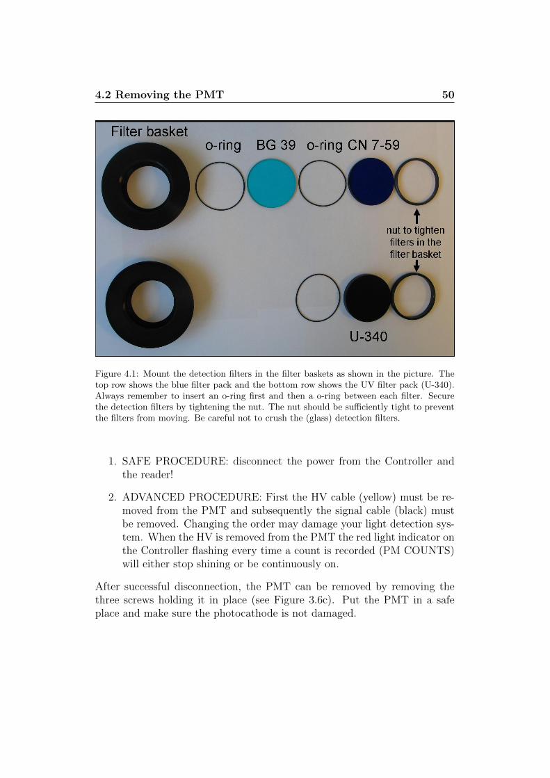
Figure 4.1 shows how the detection filters should be mounted in the filterbasket. Use the nut to secure the filters in the filter basket. The detectionfilters are made of glass so care should be taken when tightening the nut -tightening the nut too much may result in cracks in the filters. Rememberto inset o-rings at each interface.
4.2 Removing the PMT
Never expose the photocathode of the PMT directly to white light. Alwaysuse subdued light when removing/mounting the PMT. There are two waysin which one can disconnect the PMT:
4.2 Removing the PMT 50
Figure 4.1: Mount the detection filters in the filter baskets as shown in the picture. Thetop row shows the blue filter pack and the bottom row shows the UV filter pack (U-340).Always remember to insert an o-ring first and then a o-ring between each filter. Securethe detection filters by tightening the nut. The nut should be sufficiently tight to preventthe filters from moving. Be careful not to crush the (glass) detection filters.
1. SAFE PROCEDURE: disconnect the power from the Controller andthe reader!
2. ADVANCED PROCEDURE: First the HV cable (yellow) must be re-moved from the PMT and subsequently the signal cable (black) mustbe removed. Changing the order may damage your light detection sys-tem. When the HV is removed from the PMT the red light indicator onthe Controller flashing every time a count is recorded (PM COUNTS)will either stop shining or be continuously on.
After successful disconnection, the PMT can be removed by removing thethree screws holding it in place (see Figure 3.6c). Put the PMT in a safeplace and make sure the photocathode is not damaged.
4.3 Replacing the filter basket 51
4.3 Replacing the filter basket
Remove the the previously inserted filter basket from the OSL stimulationunit. Please ensure that the o-ring between the filter basket and the OSLstimulation unit is in place before inserting the new filter basket. If thiso-ring is missing a light leak has been introduced into the system.
4.4 Disabling the blue LEDs
If the blue filter pack is positioned in the OSL stimulation unit the blue LEDsshould be disabled manually to reduce the risk of shining blue stimulationlight directly into the PMT and thereby damaging it. The blue LEDs aredisabled using the switch on the back of the Controller (see Figure 7.1). Theblue LEDs should be enable once the U-340 detection filter is reinserted intothe stimulation unit.
4.5 Reconnecting the PMT
Before remounting the PMT ensure that the o-ring located in the bottomof the PMT is in place (see Figure 3.6b). The PMT is remounted usingthe three screws. Do not tighten them excessively since it may damage thethreads in the OSL stimulation unit.Reconnect the PMT by fist connecting the SIGNAL cable (black) and thenthe HV cable (Yellow). If the cables are connected in the reverse order thePMT preamps may be damaged. If the SAFE PROCEDURE was adaptedthen remember to reconnect the power to the Controller and the Reader.
4.6 Check for light leaks
After reconnection of the PMT it is advisable to ensure that no light leakshave been introduced into the system. This can be done by using the testprogram CONTROL.
1. Open CONTROL and press “connect to Minisys”
2. Choose the tab “Services”
3. Switch off the white room light (if it is not already off)
4. Click “Start” in the “Measure PMT counts” panel (see Figure 3.12) andnote down the “Counts:”.

4.6 Check for light leaks 52
5. Switch on the white room light and note down the “Counts:”. If thenumber of detected counts is higher when the room light is on comparedto when it is off, a light leak has been introduced. This light leak mustbe eliminated before it is advisable to use the reader.
6. Click “Stop” to stop measuring the PMT counts
7. Click“disconnect from Minisys”on the“Connection”tab in CONTROL

5
Optimising the Signal-to-Noiseratio
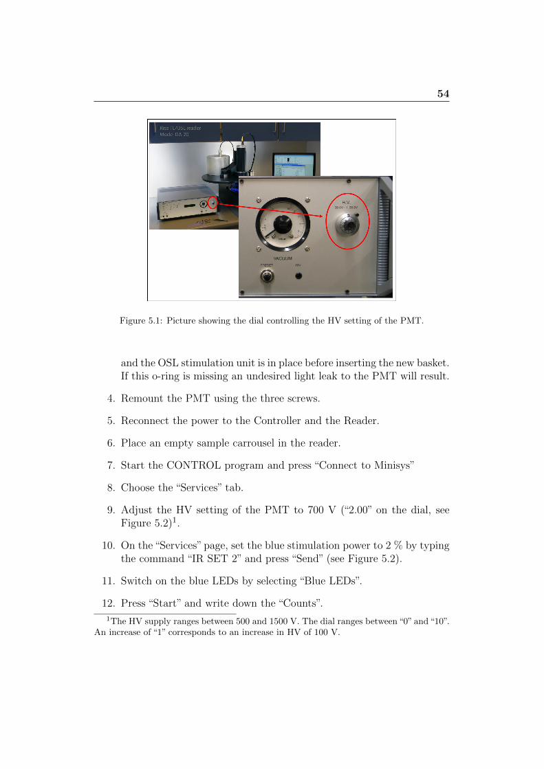
The sensitivity of the PMT can be adjusted by changing the HV setting ofthe PMT. The HV of the PMT is adjusted on the dial located to the righton the front panel of the Controller (see Figure 5.1). Each PMT has its owncharacteristics and Risø provides a “PM-Tube Testsheet” (see Figure 3.8) foreach individual PMT, in which the recommended HV setting for the PMTis indicated. However, this setting may not be optimal with respect to thesignal-to-noise (S/N) ratio. The following section describes a procedure foroptimising the S/N ratio by adjusting the HV setting. Optimising the S/Nratio is particularly important when working with weak signals comparableto the PMT dark count.
In order to optimise the S/N ratio properly the PMT must have beenmounted and connected for at least one week to ensure that is has reacheda stable condition. During the optimisation process we make use of the lightfrom the blue LEDs. To reduce the amount of light reaching the PMT it isvery important to use the neutral density filter (Schott NG9 - OD 7.5) whichis provided with the reader. If this filter is not in place the PMT may bedamaged.
1. Disconnect the power to the Controller and the Reader.
2. In subdued light remove the three screws on the bottom flange of thePMT (see Figure 3.6).
3. Replace the existing filter basket with that containing the 5 mm SchottNG9 neutral density filter (originally delivered mounted in a separatefilter basket). Please ensure that the o-ring between the filter basket
54
Figure 5.1: Picture showing the dial controlling the HV setting of the PMT.
and the OSL stimulation unit is in place before inserting the new basket.If this o-ring is missing an undesired light leak to the PMT will result.
4. Remount the PMT using the three screws.
5. Reconnect the power to the Controller and the Reader.
6. Place an empty sample carrousel in the reader.
7. Start the CONTROL program and press “Connect to Minisys”
8. Choose the “Services” tab.
9. Adjust the HV setting of the PMT to 700 V (“2.00” on the dial, seeFigure 5.2)1.
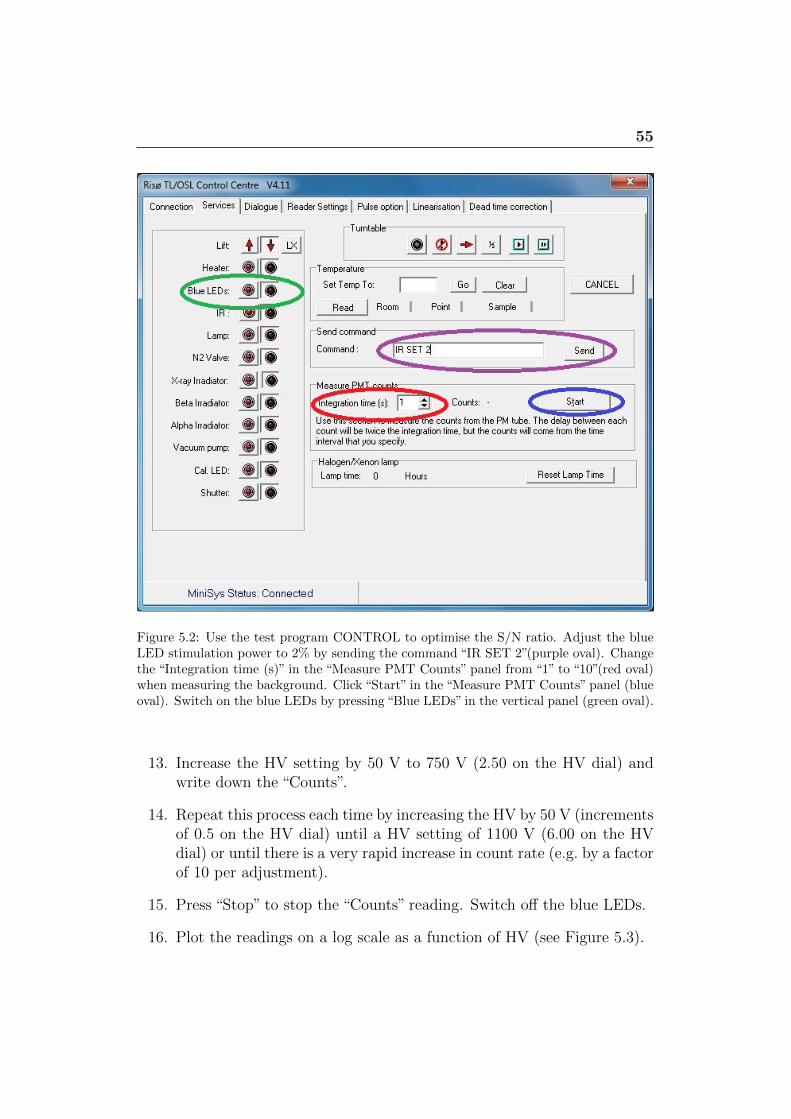
10. On the “Services” page, set the blue stimulation power to 2 % by typingthe command “IR SET 2” and press “Send” (see Figure 5.2).
11. Switch on the blue LEDs by selecting “Blue LEDs”.
12. Press “Start” and write down the “Counts”.
1The HV supply ranges between 500 and 1500 V. The dial ranges between “0” and “10”.An increase of “1” corresponds to an increase in HV of 100 V.
55
Figure 5.2: Use the test program CONTROL to optimise the S/N ratio. Adjust the blueLED stimulation power to 2% by sending the command “IR SET 2”(purple oval). Changethe “Integration time (s)” in the “Measure PMT Counts” panel from “1” to “10”(red oval)when measuring the background. Click “Start” in the “Measure PMT Counts” panel (blueoval). Switch on the blue LEDs by pressing “Blue LEDs” in the vertical panel (green oval).
13. Increase the HV setting by 50 V to 750 V (2.50 on the HV dial) andwrite down the “Counts”.
14. Repeat this process each time by increasing the HV by 50 V (incrementsof 0.5 on the HV dial) until a HV setting of 1100 V (6.00 on the HVdial) or until there is a very rapid increase in count rate (e.g. by a factorof 10 per adjustment).
15. Press “Stop” to stop the “Counts” reading. Switch off the blue LEDs.
16. Plot the readings on a log scale as a function of HV (see Figure 5.3).

56
17. Change the “Integration time (s)” in the “Measure PMT Counts” panelfrom“1”to“10”2 (see Figure 5.2). You will now measure the dark count(N) as a function of HV.
18. Turn the HV back to 700 V (2.00 on the HV dial) and repeat themeasurements in steps of 50 V as before but with the blue LEDs turnedoff.
19. Calculate the S/N ratio at each HV setting to determine the optimalHV setting. The optimal setting is where the S/N ratio is large andthe signal (S) is within the “plateau” region. In the example shown in5.3, the setting lies between 800 and 900 V.
20. Select the “Connection” tab and disconnect. Close the CONTROLprogram.
21. Adjust the HV setting of the PMT to this chosen setting.
You may use the Excel template“PMT-XXXXX.xltx”in the Extra\Instructionsfolder on your hard drive or on your installation disc to plot Signal, Back-ground and S/N ratio as shown in Figure 5.3.
2The longer this time is selected to be the more accurate the count will be, but theoptimisation process will also take longer.
57
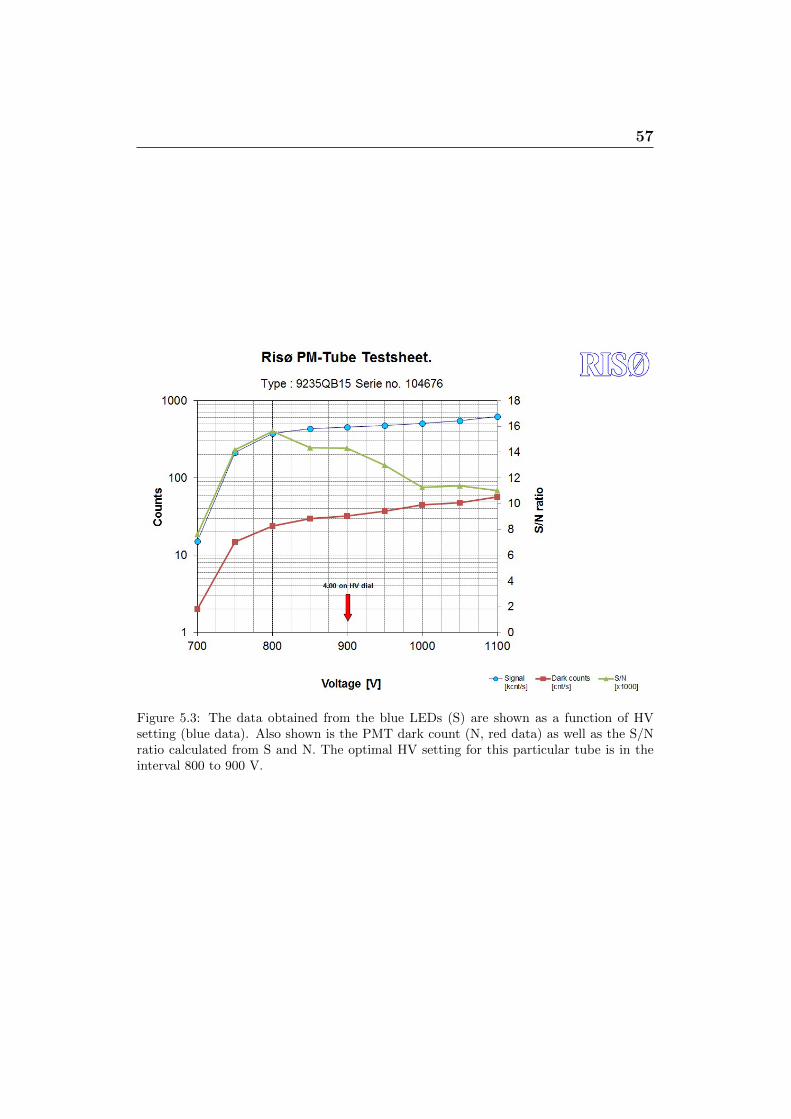
Figure 5.3: The data obtained from the blue LEDs (S) are shown as a function of HVsetting (blue data). Also shown is the PMT dark count (N, red data) as well as the S/Nratio calculated from S and N. The optimal HV setting for this particular tube is in theinterval 800 to 900 V.
6
Dead time correction
When the PMT detects a photon it gives rise to a current pulse which has aduration of approximately 20 to 30 ns. In this time interval the PMT is notable to detect additional photons. As a result of this “dead time” the PMTcounting system becomes significantly non-linear at high count rates. Foran uncorrected system we would not recommend accepting data with countrates > 5 Mcps. However, it is possible to correct for this dead time lossby enabling the “Dead time correction” in “System options” in the SequenceEditor program. This enables the system to be used up to a count rate ofabout 40 Mcps.
The actual dead time relevant to a particular system should be measuredusing the CONTROL program as described below.
1. Insert the neutral density filter (5 mm Schott NG9-OD 7.5) as a detec-tion filter (see section 4 or 5).
2. Place a sample carrousel in the Reader with an empty disc/cup inposition 1.
3. Open the CONTROL program, connect to Minisys, and press “Start”in the “Dead time correction” window.
The blue stimulation LEDs are then automatically switched on and thecount rate as a function of LED power is measured. When the power reaches100 % or the count rate exceeds 15 Mcps the program stops and the deadtime is calculated.
The dead time can be saved and stored, so it can be used automaticallyby the Sequence Editor. This is done by pressing “Save to System Setup”in the bottom right corner of the “Dead time correction” window. The deadtime correction value can also be entered manually in the “Systems Options”in the Sequence Editor.
59
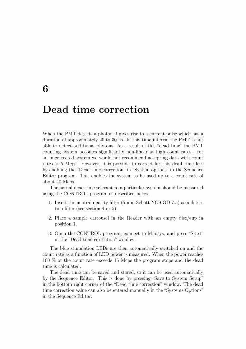
Figure 6.1: Light detected by the PMT in the dead time correction routine. The power ofthe blue LEDs is ramped from 0 to 100 % or until the count rate exceeds 15 Mcps. Theneutral density filter NG9 is used as detection filter.
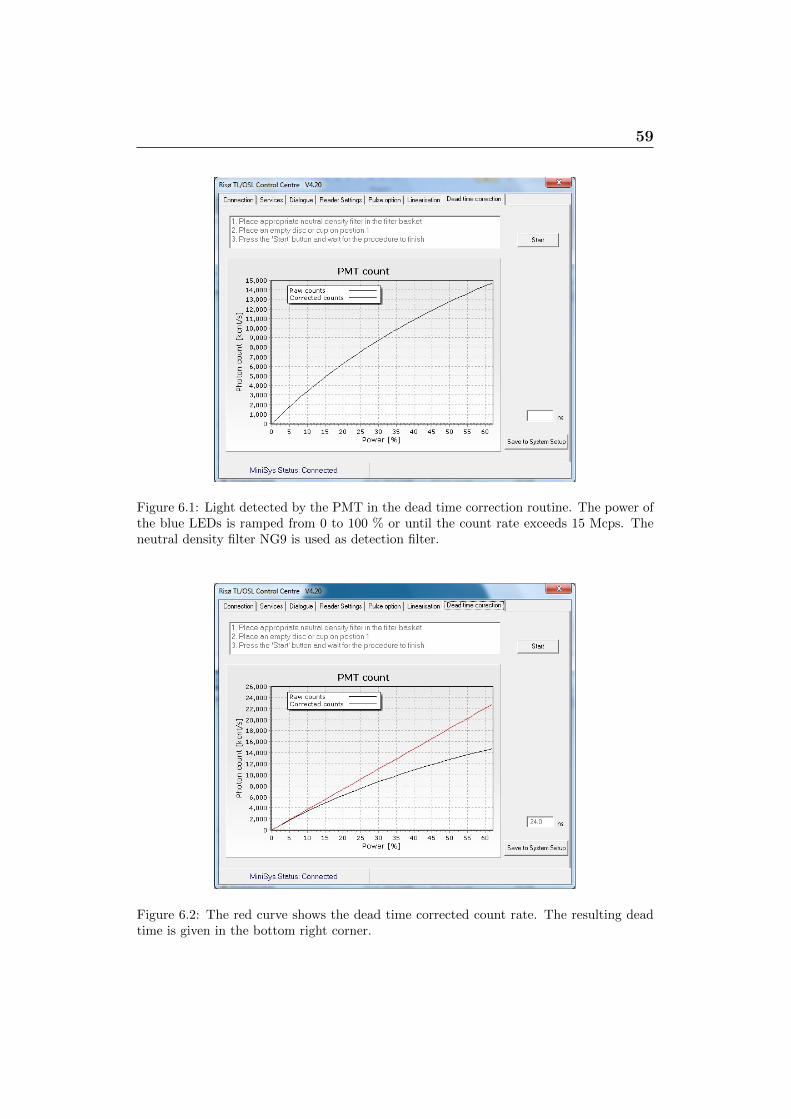
Figure 6.2: The red curve shows the dead time corrected count rate. The resulting deadtime is given in the bottom right corner.

7
Frequently answered questions
In this section you will find a list of questions that we frequently answer.
7.1 Power requirements
1. Do I need to switch off the power to the reader? It is OK to leave theequipment ON all the time. Only turn it off if you will not be using itfor a few weeks.
2. What is the power consumption of the reader? The peak power con-sumption is about 120 W. If power failure is known to occur the use ofa battery driven 500 W UPS (uninterruptible power supply) is recom-mended, to ensure a reliable supply of power.
7.2 User PC requirements
3. What is the recommended PC configuration? We recommend a Pen-tium 4 (or better) with Windows XP or Vista installed. The PC musthave a 9-pin RS-232 serial connector to be able to connect to the Con-troller.
4. Is there a regional setting that I must choose? It is very important thatthe user PC is using a “.” (full stop) as decimal separator and not a “,”(comma). In Windows XP this is setup in the Control Panel/Regionaland Language Options/Regional options. In Vista it is setup in theControl Panel/Regional and Language Options/Formats. Most conti-nental language options (e.g. German and French) will use the “,” as a
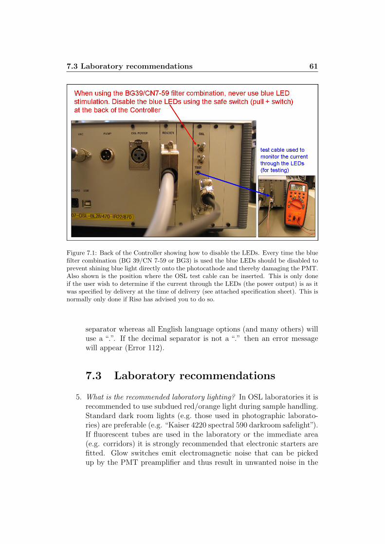
7.3 Laboratory recommendations 61
Figure 7.1: Back of the Controller showing how to disable the LEDs. Every time the bluefilter combination (BG 39/CN 7-59 or BG3) is used the blue LEDs should be disabled toprevent shining blue light directly onto the photocathode and thereby damaging the PMT.Also shown is the position where the OSL test cable can be inserted. This is only doneif the user wish to determine if the current through the LEDs (the power output) is as itwas specified by delivery at the time of delivery (see attached specification sheet). This isnormally only done if Risø has advised you to do so.
separator whereas all English language options (and many others) willuse a “.”. If the decimal separator is not a “.” then an error messagewill appear (Error 112).
7.3 Laboratory recommendations
5. What is the recommended laboratory lighting? In OSL laboratories it isrecommended to use subdued red/orange light during sample handling.Standard dark room lights (e.g. those used in photographic laborato-ries) are preferable (e.g. “Kaiser 4220 spectral 590 darkroom safelight”).If fluorescent tubes are used in the laboratory or the immediate area(e.g. corridors) it is strongly recommended that electronic starters arefitted. Glow switches emit electromagnetic noise that can be pickedup by the PMT preamplifier and thus result in unwanted noise in the
7.4 Changing filters 62
measurements.The Risø TL/OSL reader is light tight enabling the use of normal whitelight during measurement. It is recommended that the light switch forwhite light is placed high on the wall to avoid the risk of switching onwhite light while samples are being prepared.
6. What is the recommended laboratory climate? The PMT is sensitiveto temperature and humidity. The laboratory temperature should notexceed 30◦C and the humidity should be below 80%.
7. Is it a good idea to combine the OSL laboratory with the chemistry lab-oratory? No! In fact air flow between the chemical sample preparationroom and the reader room should be avoided. Over time acid fumeswill damage the electronic components inside the reader.
7.4 Changing filters
8. How do I change filters? : To change filters the PMT must be removedfrom the OSL stimulation unit.
• The signal cable (black) must always be connected when connect-ing or disconnecting the HV cable (yellow), i.e.:
a) Disconnect: HV cable first
b) Reconnect: signal cable first
If in doubt then switch off the power to the entire system
• Make sure the thick o-ring below the filter basket and the thinnero-ring in the bottom flange of the photomultiplier tube are in place
• No white light when the photomultiplier tube is removed from theOSL stimulation unit
9. Which stimulation light sources can I use with which filter combination?ONLY use IR stimulation with the BG 39/CN 7-59 or BG3 (blue) filtercombination. NEVER use blue LEDs since this could severely damagethe photomultiplier tube. You can switch off the blue LEDs with theswitch at the back of the Control Box (see Figure 7.1):
a) Using U-340 filter: IR and blue switch can be on
b) Using blue filter pack: blue switch must be off
7.5 Nitrogen requirements 63
7.5 Nitrogen requirements
10. Why do I need Nitrogen? Pressurized nitrogen is required when samplesare heated above 200◦C and to activate the pneumatically-controlledbeta and alpha irradiators. A high quality pressure regulator must beprovided that can maintain a stable output pressure of 2.5 bar (0.25MPa). 1/4” NPT threads will fit the nitrogen tube connectors providedby Risø.For the control of the irradiator(s) we suggest the use of a separatecompressed air source. This can either be piped compressed air (ifsuch an installation already exists in your laboratory) or a separatebottle of nitrogen (or air) equipped with a pressure regulator (output:2.5 bar). The extra nitrogen bottle is recommended as this is a “clean”source and is convenient as the nitrogen consumption for the controlof the irradiators is extremely low (a normal 40 l bottle should last formore than one year).
11. What is the required pressure on the N2 bottle? Gas pressure on theoutput dial on the N2 bottle should be below 2.5 bar (0.25 MPa)
12. What is the recommended Nitrogen flow rate? Typical N2 flow rate isabout 1 liter/min. The flow rate is adjusted on the flow meter locatedon the reader (to the right). The Nitrogen must be switched on in orderto adjust the flow rate. Only use N2 when you heat above 200◦C.
7.6 Vacuum
13. Is the system vacuum tight? Yes, it is.
14. How do I evacuate the measurement chamber? A vacuum pump mustbe connected to the reader (at the back). The vacuum pump musthave a KF NW 25 connection and a maximum power consumption of500 W (e.g. the Leybold Trivac D8B, 220V, RED. NW25-16KF fromGranzow A/S (www.granzow.dk)). It is also desirable to fit an oil mistfilter to avoid air pollution in the laboratory.
15. When do I need vacuum? If the Risø TL/OSL reader is equipped withan alpha source the measurement chamber should be evacuated beforealpha irradiation is undertaken. Evacuating the chamber to about 0.1bar is usually sufficient.
7.7 Operation 64
7.7 Operation
16. How do I open the reader? The reader is opened and closed usingthe two buttons located in the left corner on the front panel of theController. Pressing “UP” will make the reader lid open up to the left(see picture on the title page). Pressing “DOWN” will make the readerlid close. Do not release the button until the reader lid stops moving.If the button is released before the lid is fully closed the lid movementwill stop automatically for security reasons.
17. Any advice with respect to placing the discs/cups on the sample car-rousel? Please ensure that you place the discs on the DISCS samplecarrousel and the cups on the CUPS sample carrousel. Before placingthe discs/cups wipe the bottoms clean of grains to optimise the thermalcontact between sample and heating element.
18. Any advice with respect to placing the sample carrousel in the reader?When you insert the sample carrousel in the measurement chamber(especially in the dark) always rotate it a little afterwards to make surethat the lift/heater is in its down position before lowering the lid.
19. When I close the lid the is a loud noise from the Controller. Why?Controllers delivered after 1.1.2015 will have an audible alarm that willsound, if the heater lift is up when you try to close the lid. This is tomake you aware of the potential risk of damaging the heater element ifthe sample carousel is in the reader while closing the lid. To close thelid when the heater lift is up, remove the sample carousel first. To resetthe heater lift, use the control program or switch off the Controller, andthen on again.
7.8 Maintenance and comments
20. How do I clean the reader? We recommend that you clean the heaterplate every time you change sample carrousels by wiping any grains offusing tissue paper or a soft brush. Once per month we recommend that
a) The position holes (Ø = 1 mm) in the sample carrousel (see Figure2.6b) are cleaned with a paper clip. If grains accidentally getsstuck in the position holes the system will be unable to keep trackof the sample position.

7.8 Maintenance and comments 65
b) The space where the lift mechanism is located is cleaned with asmall vacuum cleaner
c) The quartz window (located between the measurement chamber andthe OSL stimulation unit) is cleaned with tissue paper dipped inalcohol. This interface may become dirty as a direct result of usingsilicon oil to mount sample grains onto the sample discs.
d) The outer rim of the bottom of the lid is cleaned using a little alcohol(Do NOT clean the rubber seal below the lid on the reader body).
e) The sample carrousels are washed with water and soap to preventcontamination with sample material.
References
Andersen, C. E., Bøtter-Jensen, L., and Murray, A. S. (2003). A mini X− raygenerator as an alternative to a 90Sr/90Y beta source in luminescence dat-ing. Radiation Measurements, 37:557–561.
Ballarini, M., Wintle, A. G., and Wallinga, J. (2006). Spatial variation ofdose rate from beta sources as measured using single grains. Ancient TL,24 No.1:1–8.
Bray, H. E., Bailey, R. M., and Stokes, S. (2002). Quantification of cross-irradiation and cross-illumination using a Risø TL/OSL DA-15 reader. Ra-diation Measurements, 35:275–280.
Bøtter-Jensen, L., Andersen, C. E., Duller, G. A. T., and Murray, A. S.(2003). Developments in radiation, stimulation and observation facilitiesin luminescence measurements. Radiation Measurements, 37:535–541.
Bøtter-Jensen, L., Bulur, E., Duller, G. A. T., and Murray, A. S. (2000).Advances in luminescence instrument systems. Radiation Measurements,32:523–528.
Bulur, E. (1996). An alternative technique for optically stimulated lumines-cence (OSL) experiment. Radiation Measurements, 26:701–709.
Hutt, G., Jaek, I., and Tchonka, J. (1988). Optical dating: K− feldsparsoptical response stimulation spectra. Quaternary Science Reviews, 7:381–385.
Huntley, D. J., Godfrey-Smith, D. I., and Haskell, E. H. (1991). Light-induced emission spectra from some quartz and feldspars. Nuclear Tracksand Radiation Measurements, 18:127–131.
Markey, B. G., Bøtter-Jensen, L., and Duller, G. A. T. (1997). A new flexi-ble system for measuring thermally and optically stimulated luminescence.Radiation Measurements, 27:83–89.
REFERENCES 67
McKeever, S. W. S., Markey, B. G., and Akselrod, M. S. (1996). Pulsedoptically stimulated luminescence dosimetry using α−Al2O3:C. RadiationProtection Dosimetry, 65:267–272.
Spooner, N. A. and Allsop, A. (2000). The spatial variation of dose ratefrom 90Sr/90Y beta sources for use in luminescence dating. RadiationMeasurements, 32:49–56.
Thomsen, K. J., Bøtter-Jensen, L., Denby, P. M., and Murray, A. S. (2006).Luminescence response to irradiation using mini X− ray generators. Nu-clear Instruments and Methods in Physics Research Section B, 252:267–275.
Related Documents