Ensuring reservoir safety into the future. Thomas Telford, London 2008 The Repair of Llyn Morwinion Dam SIMON R HICKMAN (Atkins Ltd) ANDY K HUGHES (Atkins Ltd) L STUART DAVIES (Dwr Cymru) SYNOPSIS. In 2000, observed settlement of the crest of Llyn Morwinion over its outlet conduit, and sediment within this conduit associated with seepage into it, led to concern that the dam was suffering from internal erosion of the core. Initially, a remedial procedure of constructing a concrete plug in the conduit under the core was proposed but, following another inspection, it was recommended that the cause of the settlement be further investigated, the dam made good and seepage minimized. This paper describes the further investigation and recommended remedial works. INTRODUCTION Llyn Morwinion reservoir is retained behind a 4m high embankment dam constructed in 1879, although the water is only raised approximately 2.4 m above the lowest natural ground level, the stream level at the toe of the embankment. The report of a Section 10 inspection of the reservoir on 18 March 2004 noted “significant leakage of sediment-bearing water into the culvert in the vicinity of the puddle clay core”. This was first noted in August 2000, as was a depression in the crest within the core zone. A recommendation was made to fill the conduit with concrete but, following a request for Dr Hughes to carry out a further inspection, it was concluded that an alternative solution might be identified that would not restrict future entry to the conduit and, thus, access for future inspection and repair to the existing outlet pipes of cast iron and uPVC materials under the direction of a Qualified Engineer. It was recommended that further investigation be carried out and measures taken to repair the embankment where depression had occurred, and identify where leaks into the conduit are occurring and seal these under the direction of a Qualified Civil Engineer.

Welcome message from author
This document is posted to help you gain knowledge. Please leave a comment to let me know what you think about it! Share it to your friends and learn new things together.
Transcript
Ensuring reservoir safety into the future. Thomas Telford, London 2008
The Repair of Llyn Morwinion Dam
SIMON R HICKMAN (Atkins Ltd)
ANDY K HUGHES (Atkins Ltd)
L STUART DAVIES (Dwr Cymru)
SYNOPSIS. In 2000, observed settlement of the crest of Llyn Morwinion
over its outlet conduit, and sediment within this conduit associated with
seepage into it, led to concern that the dam was suffering from internal
erosion of the core. Initially, a remedial procedure of constructing a
concrete plug in the conduit under the core was proposed but, following
another inspection, it was recommended that the cause of the settlement be
further investigated, the dam made good and seepage minimized. This
paper describes the further investigation and recommended remedial works.
INTRODUCTION
Llyn Morwinion reservoir is retained behind a 4m high embankment dam
constructed in 1879, although the water is only raised approximately 2.4 m
above the lowest natural ground level, the stream level at the toe of the
embankment.
The report of a Section 10 inspection of the reservoir on 18 March 2004
noted “significant leakage of sediment-bearing water into the culvert in the
vicinity of the puddle clay core”. This was first noted in August 2000, as
was a depression in the crest within the core zone.
A recommendation was made to fill the conduit with concrete but, following
a request for Dr Hughes to carry out a further inspection, it was concluded
that an alternative solution might be identified that would not restrict future
entry to the conduit and, thus, access for future inspection and repair to the
existing outlet pipes of cast iron and uPVC materials under the direction of a
Qualified Engineer.
It was recommended that further investigation be carried out and measures
taken to repair the embankment where depression had occurred, and identify
where leaks into the conduit are occurring and seal these under the direction
of a Qualified Civil Engineer.

ENSURING RESERVOIR SAFETY
The results of this investigation resulted in the identification of the hard
horizon as shown on Figure 1.
Figure 1 – Longitudinal section identifying hard horizon & conduit
This paper describes the investigation of this leakage and its proposed
remediation to ensure that the embankment is made safe.
EMBANKMENT DETAILS & HISTORY OF WORKS
The earliest information of the dam appears to be a drawing prepared in
1977 by Ward Ashcroft and Parkman in 1977 entitled, “General
arrangement and section through the dam”, but there are no records of the
geology of the dam site or the reservoir basin or indeed any other drawings
identifying features at the dam.
This drawing identifies an embankment with a 3m wide crest with central
1.8m puddle clay core contained within vertical dry-stone walls. These are
supported by a “hearting” at 1 in 3.25 upstream and 1 in 2 downstream
slopes surfaced by dry stone pitching. The outlet capacity was increased
when the original 300m diameter cast iron outlet pipe from an upstream
tower was duplicated in 1983 by a 300mm uPVC pipe passing through the
original approximately 1.8m D shaped conduit. The original outlet has since
been altered to be a dedicated draw-down outlet.
A draw-down facility is provided by both these pipes although the upstream
inlet pipework has been moved upstream within the reservoir basin,
increasing the available draw-down by over 400,000 m3.
The reservoir has a capacity of some 510,000m3 and a surface area of
113,000m2, and is a very important source of water for treatment and
onward transmission to the Ffestiniog area.

HICKMAN, HUGHES & DAVIES
FAILURE FEATURES
The observation in 2000 of sediment in the conduit and settlement of the
crest lead to the concern that Llyn Morwinion might be in danger of failure
by internal erosion.
Monitoring of seepage the quantity and quality of water into the conduit was
initiated, as was deposition into the conduit.
The flow into the conduit has been measured since 2001 and the Figure 2
below demonstrates that the flow rate mirrors the changes in reservoir water
level with a rate of approximately 0.32 l/s at TWL. This rate has not
increased although there are variable higher rates recorded, up to 0.65 l/s in
January of 2004 and 2005 which might indicate that surface rainfall into the
downstream shoulder influences the flows.
Figure 2 – Leakage into the Outlet Conduit from 2001
A preliminary investigation was carried out with boreholes drilled and
piezometers placed in locations indicated in Figure 3.

ENSURING RESERVOIR SAFETY
Figure 3 – Plan of Llyn Morwinion - Location of boreholes and piezometers
placed in 2001
Figure 4 – Schematic log of borehole BH1 in the depression on the crest
A figurative log of the borehole drilled into the depression is given in Figure
4. Worryingly, this identified voids up to a metre below crest level and wet
HICKMAN, HUGHES & DAVIES
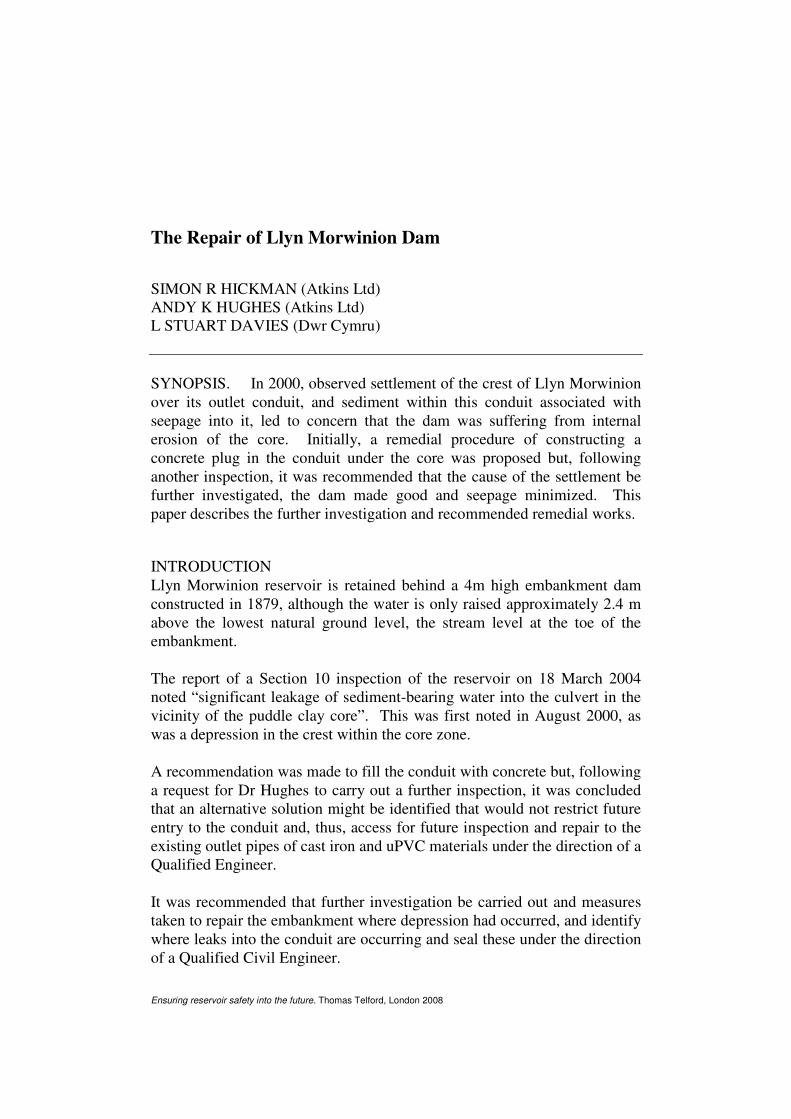
blue puddle clay above the crown to the conduit. The piezometers again
mirrored the water level in the reservoir with a rapid response to changes in
water level. At the same time survey pegs were installed in the locations
shown in Figure 5.
Figure 5 – Location of survey pins placed in the crest in 2001
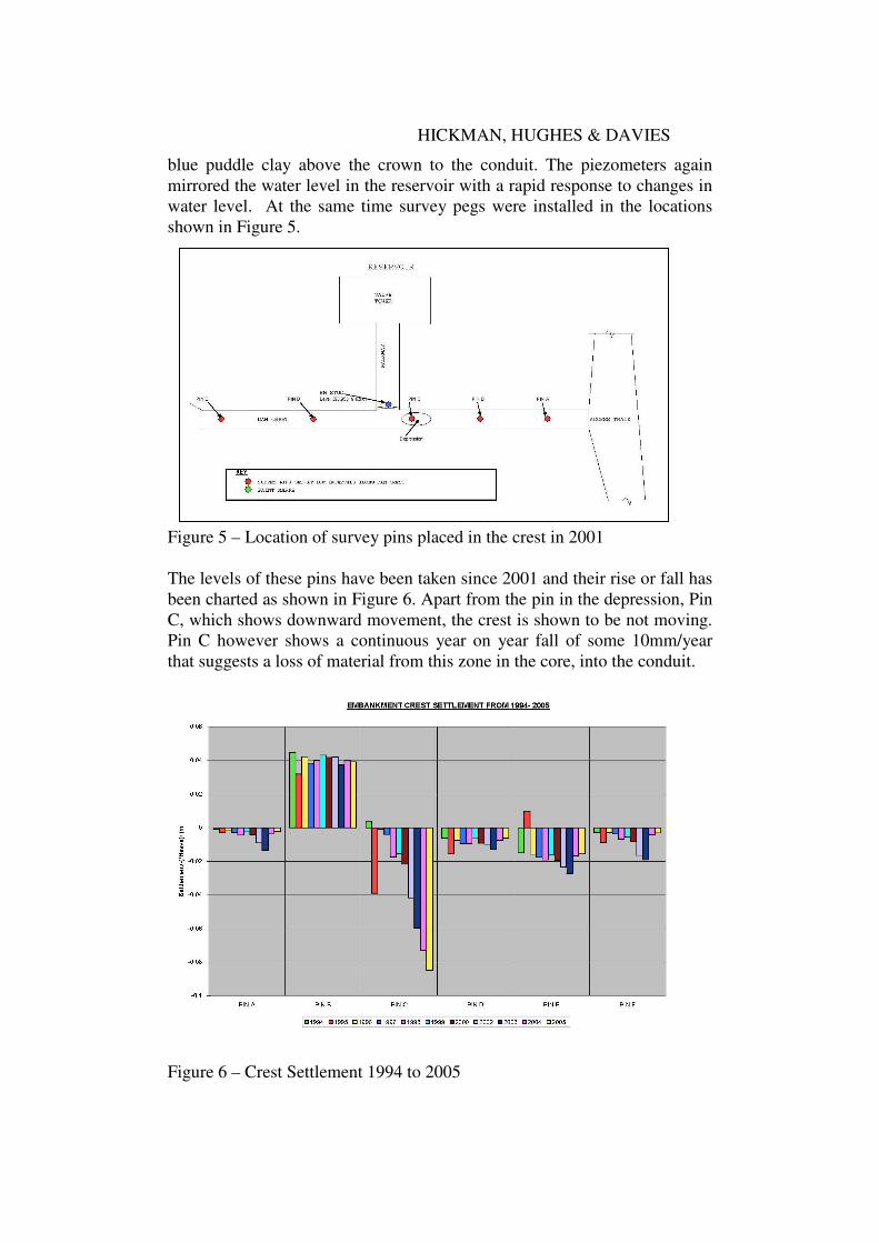
The levels of these pins have been taken since 2001 and their rise or fall has
been charted as shown in Figure 6. Apart from the pin in the depression, Pin
C, which shows downward movement, the crest is shown to be not moving.
Pin C however shows a continuous year on year fall of some 10mm/year
that suggests a loss of material from this zone in the core, into the conduit.
Figure 6 – Crest Settlement 1994 to 2005
ENSURING RESERVOIR SAFETY
Having identified a potential failure mode of internal erosion the Inspecting
Engineer made a recommendation to fill the conduit with concrete. The
Undertaker was concerned that this recommendation might not be the best
solution to the problem and requested advice from Atkins.
Following an inspection, it was recommended that the conduit should not be
filled with concrete, that further ground investigation be carried out to
identify the route of the leak into the conduit, that this leak be sealed and the
embankment be repaired, leaving the conduit open so that the pipes and
valves could be maintained. It was considered important to identify the
source of the leak and minimise it, rather than probably diverting it
elsewhere.
GROUND INVESTIGATION
The results from the earlier ground investigations highlighted the voids and
“changed” materials above the outlet conduit shown in Figure 4, but further
information was required.
A Ground Investigation (GI) contract was designed to provide information
on
• the condition of the core above the conduit to identify whether the
sediment carried into the conduit originates from the core
• the depth of the embankment to the foundation
• the material and permeability of the foundation
as well as confirming the properties of the existing core material.
A GI contract under the ICE General Conditions of Contract Measurement
Version 7th
edition and Specification for ground investigation by Site
Investigations Steering Group, 1993 was let with Structural Soils Limited in
March 2007. Draft information was provided in April 2007 and a final data
report in November 2007.
The location of the proposed boreholes and exploratory pit are shown on
Figure 7.

HICKMAN, HUGHES & DAVIES
Legend
= Location
of Boreholes
= Trial Pit
Figure 7 – Plan of Embankment identifying the Location of Boreholes and
Trial Pit of the Second Phase Inspection
RESULTS OF GROUND INVESTIGATION
Preliminary logs were provided from which the laboratory testing was
defined. The GI found the following:
• the puddle core “ …. becomes locally fissured from 2.0m depth” with
refusal at 4.7m
• the foundation material is strong narrowly foliated fine to coarse schist
with slaty cleavage from refusal to over 11m.
• the trial pit identified a large flat rock covering the conduit with in situ
foundation material higher than anticipated.

ENSURING RESERVOIR SAFETY
A log of the trial pit excavated on the downstream section of the conduit
below the embankment is given in Figure 8. Whilst the internal condition of
the conduit is in good condition, the information from the trial pit
introduced uncertainty into the composition and condition of material above
the soffit of the conduit as well as that on the sides of the conduit appears to
be constructed into an excavated trench in the rock foundation. (The rock
profile is shown in Figure 1).
Figure 8 – Log of Trial Pit Downstream of the Embankment
The properties of the clay core from the results of laboratory testing are
given in Tables 1 to 3.
Table 1 – Typical Moisture Content and Plasticity Index
Borehole
No.
MC % LL % PL % PI % <425µm %
BH 2 23 40 22 18 99
BH 5 14 to 21 44 22 22 98
Table 2 – BH2: Soil Properties
Dia. Passing Fraction Percentage
0.02 87 Gravel 3
0.006 63 Sand 2
0.002 31 Silt 64
Clay 31

HICKMAN, HUGHES & DAVIES
The strength of the clay core is shown to be satisfactory with the following
results from triaxial testing.
Table 3 – BH2: Triaxial Compression Tests
Effective Cohesion (kPa) 5
Angle of Shear Resistance (degs) 27.5
The foundation material is described as a grey schist with a Rock UCS =
68MPa and a Point Load Index (IS(50)) of 4 samples ranging from 0.2 to 5.86
(MN/m2)S(50)
REMEDIAL WORKS
The findings of the ground investigation confirmed the loss of material from
the puddle clay core and identified the foundation of the embankment to be
stable.
However, the condition of the soffit to the conduit and the interface between
the conduit and the excavated trench in which the conduit was constructed
remain unknown. So a function of the remedial works became a procedure
for providing this information and the objectives of remedial works were
therefore defined to be:
• the replacement of fissured clay material in the puddle core and
making good any settlement of the core
• identification of the condition of the soffit of the outlet conduit under
the puddle core
• consolidation and reduction of permeability of
� the soffit of the conduit below the core, and
� the zone between the conduit and the excavated
trench, extending into the in-situ foundation if
fractured .
The TWL is 392.3m AOD with the crest level varying from 393.93 m AOD
to 393.98 m AOD, i.e. a freeboard of 1.6m. Elevation of the hard horizon
immediately left of conduit (looking downstream) was found to be 390.87 m
AOD and right of conduit as 390.53 m AOD. The invert of the conduit is
388.8 AOD, which demonstrates that the conduit is constructed into a trench
in the foundation rock. There are not records identifying how the conduit
was sealed in this trench.
The depth of core to the conduit soffit was identified to be approximately
3.3m and, with the TWL at 392.3 m AOD, the hydraulic head is 1.8m.
The evidence of sediment in the conduit and settlement of the core above
the conduit indicates flow into the conduit is carrying material from the
core, i.e. through the conduit soffit. However, inflow is from the side of the
conduit, which suggests the flow path is through the soffit into the one of
ENSURING RESERVOIR SAFETY
construction between the conduit and the sides of the trench in foundation
rock.
The puddle clay core requires remediation and its removal would make
available the soffit to the conduit for inspection. The soffit would be
inspected, and where possible, the zone above the sides of the conduit
within the trench. It will be essential to seal this zone to restrict migration of
soil particle through the soffit. Where necessary, dental concrete will be
placed to provide an impervious foundation to the core when replaced. A
simple grouting programme was designed to consolidate openings and seal
larger interstices in the conduit soffit and sides.
As with most grouting, a flexible design is necessary with the quantity of
pumped grout for a particular hole and zone limited to an acceptable
maximum. The proximate conduit, because it is masonry, provides a readily
available observation face but it restricts the grout pressure.
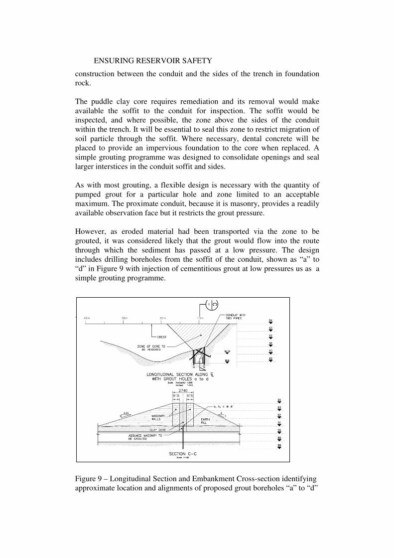
However, as eroded material had been transported via the zone to be
grouted, it was considered likely that the grout would flow into the route
through which the sediment has passed at a low pressure. The design
includes drilling boreholes from the soffit of the conduit, shown as “a” to
“d” in Figure 9 with injection of cementitious grout at low pressures us as a
simple grouting programme.
. .
Figure 9 – Longitudinal Section and Embankment Cross-section identifying
approximate location and alignments of proposed grout boreholes “a” to “d”
HICKMAN, HUGHES & DAVIES
The sequence of grouting and pressures will be determined from water
testing. This is expected to require any necessary dental work to the soffit of
the conduit to be completed prior to water tests and grouting. An alternative
procedure would be to drill the grout holes and backfill the core around
placed steel pipes placed into these grout holes. The benefit of the latter
would be to provide a head against which to grout but close inspection
would be lost.
The remedial works to the core include placing a geofabric between the core
and the vertical masonry wall to reduce any possibility of migration of clay
particles through the wall. The geofabric has been specified to retain
>10µm, the nominal size of clay flocs behind an equivalent D10 of 105 µm.
Clay removed from the core will be inspected and, where acceptable, re-
compacted in the core. Deficiencies in quantities will be made up with
imported clay of similar properties.
At the time of writing this paper in spring 2008, negotiations are ongoing
with prospective contractors to carry out the work that is expected to be
carried out during summer of 2008.
ACKNOWLEDGMENT
The authors acknowledge the supporting data provided by Dwr Cymru and
their permission to publish this paper.
REFERENCES
Structural Soils Ltd (2007). Factual Report on Ground Investigations of
Llyn Morwynion.
Related Documents


