RP386 THE RELATION OF TORQUE TO TENSION FOR THREAD-LOCKING DEVICES By H. L. Whittemore, G. W. Nusbaum, and E. 0. Seaquist ABSTRACT This investigation was made to determine, under static loads, the torsional resistance to unscrewing of nuts, with and without locking devices^ and the relationships these torques bear to the stresses in the bolt. The torque required to produce a given stress in the bolt was also determined for each device. Twenty-four manufacturers of thread-locking devices accepted the invitation to submit samples of their device for test and agreed to publication of the results. A total of 41 devices were tested, including such devices as standard nuts, jam nuts, and slotted nuts with cotter pins. Only about one-quarter of these devices showed any appreciable difference in the static torque-tension relation from that of the American National coarse-thread standard nut. CONTENTS Page I. Introduction 945 II. Scope of the investigation 947 III. Specimens 948 1. Devices 948 2. Bolts 957 3. Ordinary nuts 959 4. Vickers numbers 959 IV. Testing equipment 960 1 . Torque- tension machine 960 2. Tuckerman optical strain gage 961 V. Preparation of specimens 962 VI. Measuring specimens 962 1. General 962 2. Clearances between threads of nut and bolt 963 3. Obliquity of face of nuts 963 VII. Method of test 964 1. Torque tension ,. 964 2. Deflection of spring washers 967 VIII. Results 967 IX. Discussion 969 1. General 969 2. Persy's theory 970 3. Clearance and obliquity of bearing face of nut 971 4. Devices 971 X. Conclusions ._ 1015 I. INTRODUCTION Screw threads are widely used to fasten parts of machines and structures. Where the parts are not subject to impact and vibration, a screw thread holds securely. However, where they are subject to impact, as in a railroad- track joint, or vibration, as in an automobile engine, ordinary nuts and bolts become loose and must be tightened frequently to prevent failure. For this reason devices are used to 945

Welcome message from author
This document is posted to help you gain knowledge. Please leave a comment to let me know what you think about it! Share it to your friends and learn new things together.
Transcript
RP386
THE RELATION OF TORQUE TO TENSION FORTHREAD-LOCKING DEVICES
By H. L. Whittemore, G. W. Nusbaum, and E. 0. Seaquist
ABSTRACT
This investigation was made to determine, under static loads, the torsionalresistance to unscrewing of nuts, with and without locking devices^ and therelationships these torques bear to the stresses in the bolt. The torque requiredto produce a given stress in the bolt was also determined for each device.
Twenty-four manufacturers of thread-locking devices accepted the invitationto submit samples of their device for test and agreed to publication of the results.
A total of 41 devices were tested, including such devices as standard nuts,jam nuts, and slotted nuts with cotter pins. Only about one-quarter of thesedevices showed any appreciable difference in the static torque-tension relationfrom that of the American National coarse-thread standard nut.
CONTENTSPage
I. Introduction 945II. Scope of the investigation 947
III. Specimens 9481. Devices 9482. Bolts 9573. Ordinary nuts 9594. Vickers numbers 959
IV. Testing equipment 9601
.
Torque-tension machine 9602. Tuckerman optical strain gage 961
V. Preparation of specimens 962VI. Measuring specimens 962
1. General 9622. Clearances between threads of nut and bolt 9633. Obliquity of face of nuts 963
VII. Method of test 9641. Torque tension ,. 9642. Deflection of spring washers 967
VIII. Results 967IX. Discussion 969
1. General 9692. Persy's theory 9703. Clearance and obliquity of bearing face of nut 9714. Devices 971
X. Conclusions ._ 1015
I. INTRODUCTION
Screw threads are widely used to fasten parts of machines andstructures. Where the parts are not subject to impact and vibration,
a screw thread holds securely. However, where they are subject to
impact, as in a railroad-track joint, or vibration, as in an automobileengine, ordinary nuts and bolts become loose and must be tightenedfrequently to prevent failure. For this reason devices are used to
945
946 Bureau of Standards Journal of Research [Vol. 7
lock the screw threads. Thousands of patents have been issued
for devices of this kind, and there are many now on the market.The importance of this problem to the industries and the people
of this country led the Bureau of Standards to undertake an investi-
gation of methods of locking screw threads, to determine, if possible,
the properties of different locking devices under conditions simulating
those found in service.
A search through the technical literature gave very little informa-tion. In fact, no article bearing specifically on the problem of lock-
ing screw threads was found. No complete experimental investiga-
tion of the standard theory, developed by Persy * for the effect of
friction on the torque-tension relationship of ordinary nuts, was found,
although a few authors 2~9 have determined serewing-on torques for
a number of regular nuts.
A few tests of thread-locking devices have been made by commercialorganizations and the results used by them. A study of the reports
of tests of this kind which were available showed none that could beused as a basis for generally valid conclusions, because in no case wasan attempt made to measure the forces acting on the locking deviceduring the test, or to evaluate the significace of the other variables
which have an effect on the results. For example, if one lockingdevice is used in an air hammer, then replaced by another device, thefact that one of the devices loosened and the other did not would notprove the superiority of the one which did not loosen unless the forces
which acted on each device had been measured and found to be thesame. An assumption that the forces were the same on both devices
may lead to serious errors. The measurement of forces exerted upona machine part subjected to impact and vibration is one of the mostdifficult problems in mechanical testing, and one for which, in manycases, methods and apparatus have not been developed.A program for the investigation was therefore outlined, planned to
analyze the forces acting on screw threads which tend to unscrew themand to study the behavior of different thread-locking devices subjectedto the action of these forces under measured conditions. All knownmanufacturers of devices for preventing the unlocking of screwthreads; that is, for preventing the rotation of the nut on a bolt—wereinvited to cooperate in this investigation by submitting samples of
their devices.
Other things being equal, a locking device requiring a high torqueto unscrew it would be expected to prove more satisfactory in servicethan one requiring a low torque. A part of this program, therefore,
consisted of a study of the torque required to screw on and screw off
each locking device under static conditions. Because the conditions
1 J. V. Poncelet, Frottement des vis et des ecroux, Crelle's Journal, vol. 2, pp. 293-300, 1827. See alsoF. Grashof, Maschinenlehre (Voss, Leipzig, 1883), vol. 2, pp 265-276.
* H. Camerer, Beitrage zur Schraubenberechnung, Zeits. des V. D. I., vol. 44, pp. 1063-65, Aug. 11, 1900.» Carl Stimson, Test of Track Bolts and Wrenches, Proceedings of the American Railway Association,
vol. 17, pp 265-280, 1916.
* Oberhuber and Abele, Bolts for Use in Power Plant Construction, Mechanical Engineering, vol. 48,
pp. 500-504, May, 1926.
» George S. Case, Stresses on Bolts—Nut Dimensions—Wrench Design, Mechanical Engineering, vol.48, pp. 919-925, September, 1926.
• W. Kohler, Anzugspannungen und deren bedeutung bei der arbeit der schraube, Bergmann Mitteil-ungen, vol. 4, pp. 223-229, November-December, 1926.
1 Resistance et pose des vis et des boulons; proportions des ecroux et des cles. Pratique des IndustriesMecaniques, vol. 12, pp. 105-109, June, 1930.
• K. Schimz, Eine neue statische schraubenpriifmaschine, Maschinenbau, vol. 9, pp. 573-575, Sept. 4,1930.
» Albert Kingsburg, Experiments on the Friction of Screws, Trans. Am. Soc. Mechanical Engineers,yol. 17, pp. 96-116; 1896.
m l
sbaum,e
seaquist] Torque and Tension in Thread-Locking Devices 947
in these tests were more readily controlled and measured, this partof the program has been completed first.
The development of apparatus for determining the behavior of thesedevices under other measured conditions, particularly conditions moreclosely simulating those which occur in service, has made considerableprogress, and additional reports will be published when data havebeen obtained which warrant publication.
This report is, then, the first of the reports on this investigation of
devices for locking screw threads. It gives a drawing and description
of each of the locking devices submitted by the cooperating manu-facturers; a description of the apparatus and methods used for deter-
mining the relation between the screwing-on and screwing-off torqueson the nut and the tensile stress in the bolt. The results of the tests
are given in a series of curves, and some general conclusions have beendrawn. A fuller coordination of the experimental results and theorywill be attempted when the investigation has progressed further.
II. SCOPE OF THE INVESTIGATION
Forty-one devices were included in the investigation and are
described in detail under III, Specimens. Twenty-four manufac-turers submitted 33 locking devices from commercial stock. Someof these devices were ordinary 10 nuts which had been modified, andone was an ordinary bolt which had been modified; that is, they hadfeatures not found in ordinary nuts and bolts. These will hereafter
be referred to as "modified" nuts and "modified" bolts. Of these 33locking devices 16 were modified nuts, one was a modified bolt, andtwo had a special thread for both bolt and nut. Fourteen were separatedevices to be used with ordinary nuts, of which 10 were spring or lockwashers. With all of these separate devices U. S. standard regular
nuts were used.
In addition to the locking devices submitted by the manufacturers,the test program included the following ordinary devices: AmericanNational coarse-thread regular nut, American National fine-thread
regular nut, each of these nuts with jam nuts, and American Nationalfine-thread castellated nut with cotter pin. American Nationalcoarse-thread slotted or castellated nuts with cotter pins would havebeen included in the program if they could have been obtained com-mercially.
Because the older U. S. standard nuts are still extensively usedthere were also included tests on U. S. standard regular nuts, U. S.
standard regular nuts with jam nuts, and U. S. standard slotted nutswith cotter pins.
As it was considered desirable to make all of the tests on devicesof the same nominal size, all bolts had a nominal diameter of three-
fourths inch. This size was considered representative of the screwthreads widely used in engineering work. For the same reason, all
bolts had the American National right-hand coarse thread exceptthose used with American National fine-thread nuts and with the twodevices having a special thread.
The dimensions of the American National thread (coarse and fine)
nuts and bolts are given in the Report of the National Screw Thread
if American National and U. S. standard nuts will hereafter be referred to as "ordinary nuts" and Ameri-can National bolts as "ordinary bolts."
948 Bureau of Standards Journal of Research [Von
Commission, Bureau of Standards Miscellaneous Publication No. 89,
and those of the U. S. standard thread in the Report of the Special
Committee on a Uniform System of Screw Threads, Journal of theFranklin Institute, volume 49, pages 53-57, 1865 (adopted March 16,
1865, 1. c, p. 280).
The %-inch American National coarse thread has 10 threads perinch. The regular nut is % inch thick and 1 )i inches across flats of
the hexagon. The jam nut is J{6 inch thick. The American Na-tional fine thread has 16 threads per inch. The regular nut andthe jam nut are the same sizes as the coarse-thread nuts.
The U. S. standard thread, like the American National coarse
thread, has 10 threads per inch, but the regular nut is larger, being %inch thick and l){ inches across the flats of the hexagon. The U. S.
standard does not prescribe the dimensions of jam nuts. The jamnut was, therefore, made 7
/w inch thick, the same as for the AmericanNational nut. The differences between the American National coarse
thread and the U. S. standard thread are so small that a U. S. standardnut may be used on an American National coarse-thread bolt.
III. SPECIMENS1. DEVICES
To each device a symbol was assigned, viz: I, II, III, etc., for non-proprietary devices; A, B, C, etc., and AA, BB, CC, etc., for proprie-
tary devices; of these the devices designated by double letters werespring washers.A description (and for the devices designated by letters a drawing
to scale) of each device follows. Unless otherwise noted in the descrip-
tion, the device was made of steel.
Device I was an American National coarse-thread regular nut.Device II was a U. S. standard regular nut.Device III was an American National fine-thread regular nut.Device IV was an American National coarse-thread regular nut and
a jam nut.
Device V was a U. S. standard regular nut and a jam nut.Device VI was an American National fine-thread regular nut and a
jam nut.
Device VII was a U. S. standard slotted nut and a cotter pin,
% inch in diameter. The slots in the nut were %& inch wide and }{
inch deep.
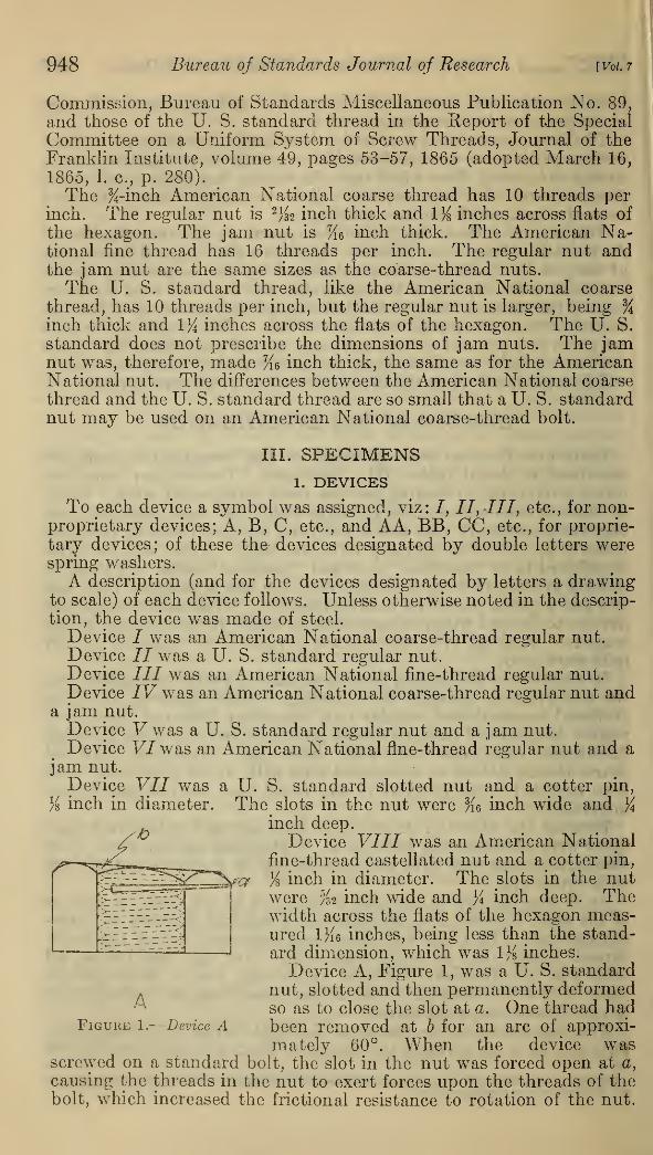
/ Device VIII was an American National|ia""^~~^~"' "^ -^_ fine-thread castellated nut and a cotter pin,
r>~ -^^^^Vcy K inch in diameter. The slots in the nutl^T^zzy^T' were %2 inch wide and }i inch deep. The5rr5f-Vr^J width across the flats of the hexagon meas-i::::^ ured 1}{6 inches, being less than the stand-• * fV
*' ard dimension, which was 1% inches.
Device A, Figure 1, was a U. S. standard
A nut, slotted and then permanently deformedA so as to close the slot at a. One thread had
Figure 1.
—
Device A been removed at 6 for an arc of approxi-
mately 60°. When the device wasscrewed on a standard bolt, the slot in the nut was forced open at a,
causing the threads in the nut to exert forces upon the threads of thebolt, which increased the frictional resistance to rotation of the nut.
WhittemoreNusbaum, Seaquist,J Torque and Tension in Thread-Locking Devices 949
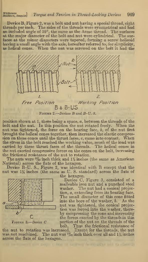
Device B, Figure 2, was a bolt and nut having a special thread, eightthreads per inch. The sides of the threads were symmetrical and hadan included angle of 29°, the same as the Acme thread. The surfacesat the major diameter of the bolt and nut were cylindrical. The sur-
faces at the minor diameters were tapered, forming a screw helicoid
having a small angle with the axis, hereafter referred to, for simplicity,
as helical cones. When the nut was screwed on the bolt it had the
Nut
Bolt-
/. ZFree Position Working Position
B& B-USFigure 2.
—
Devices B and B-U. S.
position shown at 1, there being a space, a, between the threads of thebolt and the nut. In this position the nut rotated freely. When thenut was tightened, the force on the bearing face, b, of the nut first
brought the helical cones together, then increased the elastic compres-sion on these cones until the thrust faces, c, came into contact. Whenthe stress in the bolt reached the working value, much of the load wascarried by these thrust faces of the threads. The helical cones in
the nut exerted compressive forces on the cones on the bolt, increasing
the frictional resistance of the nut to rotation.
The nuts were % inch thick and 1% inches (the same as AmericanNational) across the flats of the hexagon.Device B-U. S., Figure 2, was identical with B except that the
nut was 1% inches (the same as U. S. standard) across the flats of
the hexagon.Device C, Figure 3, consisted of a
malleable iron nut and a punched steel
washer. The nut had a conical projec-
tion, a, extending from its bearing face.
The small diameter of this cone fitted
into the bore of the washer, b. As the
nut was tightened, the conical projec-
tion was forced into the washer, there-
by compressing the cone and increasing
the forces exerted by the threads in this
portion of the nut on the threads of thebolt. Thus the frictional resistance of
the nut to rotation was increased. Except for the threads, the nutwas not machined. The nut was 2%2 inch thick over all and 1}{ inchesacross the flats of the hexagon.
Figure 3.
—
Device C
950 Bureau of Standards Journal of Research [Vol. 7
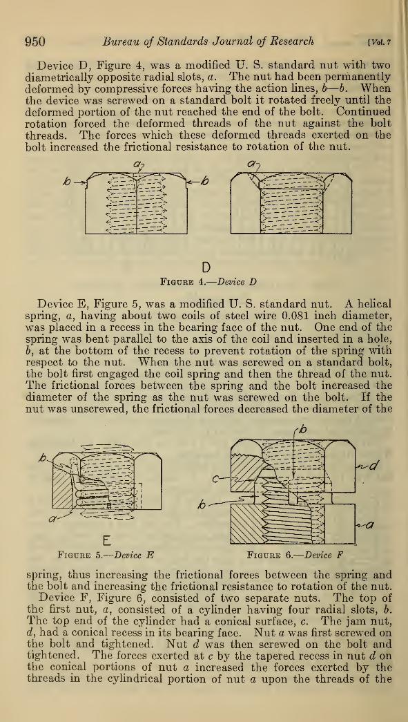
Device D, Figure 4, was a modified U. S. standard nut with twodiametrically opposite radial slots, a. The nut had been permanentlydeformed by compressive forces having the action lines, b—b. Whenthe device was screwed on a standard bolt it rotated freely until the
deformed portion of the nut reached the end of the bolt. Continuedrotation forced the deformed threads of the nut against the bolt
threads. The forces which these deformed threads exerted on the
bolt increased the frictional resistance to rotation of the nut.
DFigure 4.
—
Device D
Device E, Figure 5, was a modified U. S. standard nut. A helical
spring, a, having about two coils of steel wire 0.081 inch diameter,was placed in a recess in the bearing face of the nut. One end of thespring was bent parallel to the axis of the coil and inserted in a hole,
b, at the bottom of the recess to prevent rotation of the spring withrespect to the nut. When the nut was screwed on a standard bolt,
the bolt first engaged the coil spring and then the thread of the nut.
The frictional forces between the spring and the bolt increased thediameter of the spring as the nut was screwed on the bolt. If thenut was unscrewed, the frictional forces decreased the diameter of the
<*2^-L
a
Figure 5.
—
Device E Figure 6.
—
Device F
spring, thus increasing the frictional forces between the spring andthe bolt and increasing the frictional resistance to rotation of the nut.Device F, Figure 6, consisted of two separate nuts. The top of
the first nut, a, consisted of a cylinder having four radial slots, b.
The top end of the cylinder had a conical surface, c. The jam nut,d, had a conical recess in its bearing face. Nut a was first screwed onthe bolt and tightened. Nut d was then screwed on the bolt andtightened. The forces exerted at c by the tapered recess in nut d onthe conical portions of nut a increased the forces exerted by thethreads in the cylindrical portion of nut a upon the threads of the

WhUtemoreNusbaum, Seaquist.] Torque and Tension in Thread-Locking Devices 951
bolt and increased the frictional resistance to rotation of the nuts.
Both nuts were 1% inches across the flats of the hexagons. Thethickness of the first nut was % inch over all and that of the jamnut 5
/i inch. The recess in the jam nut was %6 inch deep. The total
thickness of threaded portions of the two nuts was l}i inches.
Device G, Figure 7, was a modified U. S. standard nut. The tophad a hole, a, in which a pin, b, was a tight fit. The portion of thepin which projected from the top of the nut was bent toward the axis
of the nut until it was parallel to the top. When the nut was screwedon a bolt, the projecting end of the pin was deflected by the threadson the bolt. When the nut was unscrewed, the pin acted as a pawl,increasing the resistance to rotation of the nut.
HFigure 7.
—
Device G Figure 8.
—
Device H
Device H, Figure 8, was a nut with an annular groove, a, in a recess
in the top. The wall of the recess had a radial slot, b. A wirespring, c, was sprung into the groove, a. One end of the spring wasbent radially outward and was restrained by the slot, b, and the otherend was bent inward to engage the bolt thread. When the nut wasscrewed on the bolt, the inner end of the spring was deflected outwardby the threads of the bolt. When the nut was unscrewed, the spring
acted as a pawl, increasing the resistance to rotation of the nut.
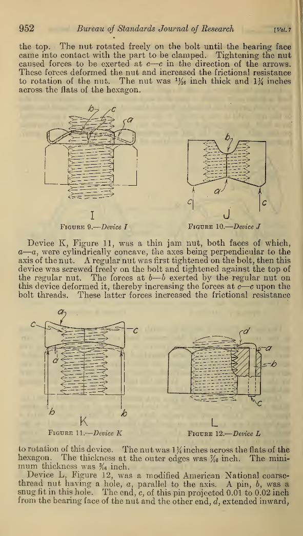
Device I, Figure 9, was a jam nut made from sheet steel 0.043 in.
thick having a conical portion, a, the inner edge of which was a single
thread, b. There were six radial slots, c, in the inner edge. After aregular nut was tightened on the bolt this device was screwed on thebolt and tightened against the top of the regular nut. The forces,
exerted by the threads of the bolt on the thread of this device, deflected
the segments of the thread inward against the roots of the bolt threads,
increasing the frictional resistance to rotation of the nut. Thedistance across the flats of the hexagon was 1%2 inch.
Device J, Figure 10, was a special nut having a shallow V-shapedgroove, a, extending diametrically across the bearing face. A deeperand narrower groove, b, parallel to a, extended diametrically across
952 Bureau of Standards Journal of Research [Vol. i
the top. The nut rotated freely on the bolt until the bearing facecame into contact with the part to be clamped. Tightening the nutcaused forces to be exerted at c—c in the direction of the arrows.These forces deformed the nut and increased the frictional resistance
to rotation of the nut. The nut was % inch thick and 1% inchesacross the flats of the hexagon.
Figure 9.
—
Device I Figure 10.
—
Device J
Device K, Figure 11, was a thin jam nut, both faces of which,a—a, were cylindrically concave, the axes being perpendicular to theaxis of the nut. A regular nut was first tightened on the bolt, then this
device was screwed freely on the bolt and tightened against the top of
the regular nut. The forces at b—b exerted by the regular nut onthis device deformed it, thereby increasing the forces at c—c upon thebolt threads. These latter forces increased the frictional resistance
Figure 11.
—
Device KL
Figure 12.
—
Device L
to rotation of this device. The nut was 1 }{ inches across the flats of thehexagon. The thickness at the outer edges was %6 inch. The mini-mum thickness was Ke inch.
Device L, Figure 12, was a modified American National coarse-thread nut having a hole, a, parallel to the axis. A pin, b, was asnug fit in this hole. The end, c, of this pin projected 0.01 to 0.02 inchfrom the bearing face of the nut and the other end, d, extended inward,
WhitiemoreNusbaum, Seaquist}ist] Torque and Tension in Thread-Locking Devices 953
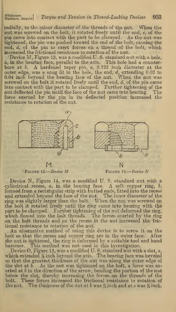
radially, to the minor diameter of the threads of the nut. When thenut was screwed on the bolt, it rotated freely until the end, c, of thepin came into contact with the part to be clamped. As the nut wastightened, the pin was pushed toward the end of the bolt, causing theend, d, of the pin to exert forces on a thread of the bolt, whichincreased the frictional resistance to rotation of the nut.
"Device M, Figure 13, was a modified U. S. standard nut with a hole,
a, in the bearing face, parallel to the axis. This hole had a counter-bore at b. A hardened taper pin, c, 0.122 inch diameter at theouter edge, was a snug fit in the hole, the end, d, extending 0.03 to
0.04 inch beyond the bearing face of the nut. When the nut wasscrewed on the bolt it rotated freely until the end, d , of the pin cameinto contact with the part to be clamped. Further tightening of thenut deflected the pin until the face of the nut came into bearing. Theforce exerted by the pin in its deflected position increased theresistance to rotation of the nut.
M NFigure 13.
—
Device M Figure 14.
—
Device N
Device N, Figure 14, was a modified U. S. standard nut with a
cylindrical recess, a, in the bearing face. A soft copper ring, b,
formed from a rectangular strip with butted ends, fitted into the recess
and extended beyond the face of the nut. The inner diameter of thering was slightly larger than the bolt. When the nut was screwed onthe bolt it rotated freely until the ring came into bearing with the
part to be clamped. Further tightening of the nut deformed the ring,
which flowed into the bolt threads. The forces exerted by the ring
on the bolt threads and on the recess in the nut increased the fric-
tional resistance to rotation of the nut.
An alternative method of using this device is to screw it on thebolt so that the recess and copper ring are in the outer face. Afterthe nut is tightened, the ring is deformed by a suitable tool and handhammer. This method was not used in this investigation.
Device O, Figure 15, was a modified U. S. standard nut with a slot, a,
which extended % inch beyond the axis. The bearing face was beveledso that the greatest thickness of the nut was along the outer edge of
the slot at 6. As the nut was tightened on the bolt, a force was ex-
erted at b in the direction of the arrow, bending the portion of the nutbelow the slot, thereby increasing the forces on the threads of thebolt.. These forces increased the frictional resistance to rotation of
the nut. The thickness of the nut at b was % inch and at c was % inch.

954 Bureau of Standards Journal of Research [Vol. 7
Device P, Figure 16, was a modified U. S. standard nut with twoparallel slots, a—a, one in each of two opposite sides of the hexagon,extending to the minor diameter of the threads. There was a shallowV-shaped groove diametrically across the bearing face in such a posi-
tion that the thickest portions, b—6, of the nut were along the openedges of the slots. When the nut was tightened on the bolt, forces
were exerted at b—b in the direction of the arrows which deformedthe nut and increased the forces which the threads in the nut exerted
oFigure 15.
—
Device Figure 16.
—
Device P
on the bolt, increasing the frictional resistance to rotation of the nut.
The nut was % inch thick at b and % inch midway between the slots.
Device Q, Figure 17, was a modified U. S. standard nut. It hadan annular recess, a, in the top. There were three equally spacedslots, 6, in the wall of the recess, which were tangential to the threads.
A key, c, was provided, having the cross section of a truncated equi-lateral triangle whose height was 0.117 inch and whose width of basewas 0.131 inch. After the nut was screwed on the bolt and tightened,
the key was placed in oneof the slots and driven be-
tween the wall of the recess
and the bolt threads, thusbending the key around the
bolt threads. The forces
exerted by the key uponthe nut and upon the
threads of the bolt in-
creased the frictional re-
sistance to rotation of the
nut.Device R, Figure 18, was
a modified U. S. standardnut. It had a recess, a, in
the bearing face. A slot,
b, tangential to the threads,extended from one of the sides of the nut through the wall of the re-
cess. A single coil helical spring, c, was provided, having the cross
section of a truncated equilateral triangle, whose height was 0.098inch and width of base was 0.11 inch. One end of this spring ex-
tended radially outward. The spring was screwed on the bolt for
one thread. The nut was then placed over the spring and the nutand spring were then rotated together. An axial force had to be
Device Q

WhittemoreNusbaum, Seaquist] Torque and Tension in Thread-Locking Devices 955
applied to the nut until it engaged the bolt threads, after which thenut and spring acted as a unit. As the nut was screwed on the bolt,
the frictional forces between the spring and the bolt caused the diam-eter of the coil of the spring to increase. When the direction of rota-
tion of the nut was reversed, the diameter of the coil of the spring wasdecreased,increasing theforces between the ,£spring and the bolt, \
which increased the fric- > —vt
tional resistance to rota-
tion of the nut.
Device S, Figure 19,
was a conical soft steel
washer having s e r r a-
tions, a,in theinner edge.
A regular nut was first
tightened on the bolt
and this device placedover the bolt with theserrations in contactwith the top of the nut.
A jam nut was screwedon the bolt and tight-
ened until the device was flattened, causing the serrations to engage
the threads on the bolt. The jam nut was then removed. The forces
exerted by the serrations upon the threads of the bolt caused fric-
tional resistance to rotation of the device. The thickness of the
washer was 0.083 inch.
An alternative method of applying this device is to flatten the
device, using a suitable piece of tubing, by blows of a hand hammer.This method was not used in this investigation.
RFigure 18.
—
Device R
Figure 19.
—
Device ST
Figure 20.
—
Device T
Device T, Figure 20, consisted of a special nut and a helical steel
spring washer. The nut had a conical seat, a, in the bearing face anda cylindrical portion, 6, extending from the bottom of the conical
seat outward beyond the face of the nut. This cylindrical portionhad two diametral slots, c, perpendicular to each other. The outsideof the spring washer, d, was conical and the inside was cylindrical.
The washer was placed in the recess, then the nut was screwed freely
79688—31 13
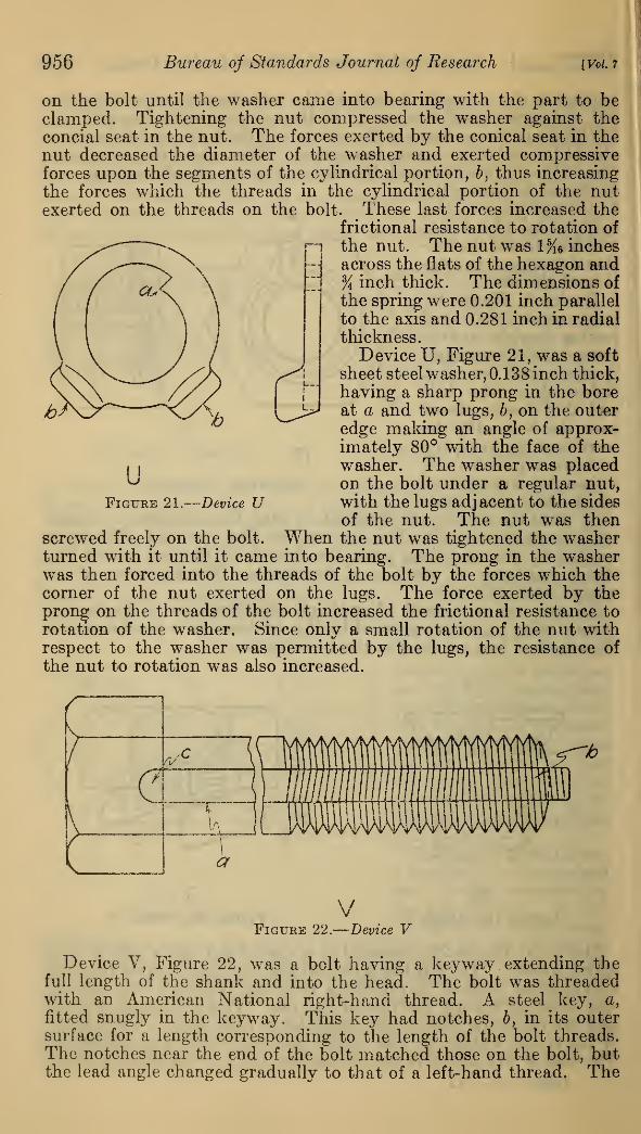
956 Bureau of Standards Journal of Research [VoL 7
on the bolt until the washer came into bearing with the part to beclamped. Tightening the nut compressed the washer against theconcial seat in the nut. The forces exerted by the conical seat in thenut decreased the diameter of the washer and exerted compressiveforces upon the segments of the cylindrical portion, b, thus increasing
the forces which the threads in the cylindrical portion of the nutexerted on the threads on the bolt. These last forces increased the
frictional resistance to rotation of»—] the nut. The nut was 1%6 inches
across the flats of the hexagon and% inch thick. The dimensions of
the spring were 0.201 inch parallel
to the axis and 0.281 inch in radial
thickness.
Device U, Figure 21, was a soft
^i sheet steel washer, 0.138 inch thick,
having a sharp prong in the boreat a and two lugs, b, on the outeredge making an angle of approx-imately 80° with the face of thewasher. The washer was placedon the bolt under a regular nut,with the lugs adjacent to the sides
of the nut. The nut was thenscrewed freely on the bolt. When the nut was tightened the washerturned with it until it came into bearing. The prong in the washerwas then forced into the threads of the bolt by the forces which thecorner of the nut exerted on the lugs. The force exerted by theprong on the threads of the bolt increased the frictional resistance to
rotation of the washer. Since only a small rotation of the nut withrespect to the washer was permitted by the lugs, the resistance of
the nut to rotation was also increased.
uFigure 21.
—
Device U
VFigure 22.
—
Device V
Device V, Figure 22, was a bolt having a keyway extending thefull length of the shank and into the head. The bolt was threadedwith an American National right-hand thread. A steel key, a,
fitted snugly in the keyway. This key had notches, b, in its outersurface for a length corresponding to the length of the bolt threads.The notches near the end of the bolt matched those on the bolt, butthe lead angle changed gradually to that of a left-hand thread. The
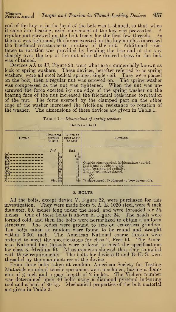
WhittemoreNusbaum, Seaquist] Torque and Tension in Thread-Locking Devices 957
end of the key, c, in the head of the bolt was L-shaped, so that, whenit came into bearing, axial movement of the key was prevented. Aregular nut screwed on the bolt freely for the first few threads. Asthe nut was tightened, the forces exerted on the key notches increasedthe frictional resistance to rotation of the nut. Additional resis-
tance to rotation was provided by bending the free end of the keysharply over the top of the nut after the desired stress in the boltwas obtained.
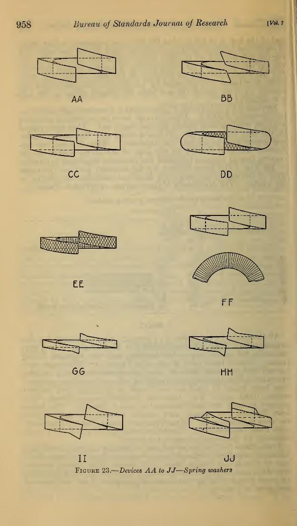
Devices AA to JJ, Figure 23, were what are commercially known aslock or spring washers. These devices, herafter referred to as springwashers, were all steel helical springs, single coil. They were placedon the bolt, then a regular nut was screwed on. The spring washerwas compressed as the nut was tightened. When the nut was un-screwed the force exerted by one edge of the spring washer on thebearing face of the nut increased the frictional resistance to rotationof the nut. The force exerted by the clamped part on the otheredge of the washer increased the frictional resistance to rotation of
the washer. The dimensions of these devices are given in Table 1.
Table 1.
—
Dimensions of spring washers
Devices AA to JJ
DeviceThicknessparallelto axis
Width atright angle
to axisRemarks
AAInch
H
HMeMeVn
Me^2
Me, %%
Inch
H
%%HHUH%Me
BBCCDD_. Outside edge rounded, inside surface knurled.EE Inside and outside knurled.FF Both faces knurled radially.GQ Ends of coil wedge-shaped.HH Do.II_... Do.JJ Wedge-shaped rib adjacent to bore on one side.
2. BOLTS
All the bolts, except device V, Figure 22, were purchased for this
investigation. They were made from S. A. E. 1020 steel, were % inchdiameter, 8.0 inches long under the head, and were threaded for 2%inches. One of these bolts is shown in Figure 24. The heads wereformed cold, and then the bolts were normalized to obtain a uniformstructure. The bodies were ground to size on centerless grinders.
Ten bolts taken at random were found to be round and straight
within 0.001 inch. The American National coarse threads wereordered to meet the specifications for class 2, Free fit. The Amer-ican National fine threads were ordered to meet the specifications
for class 3, Medium fit. Measurements showed that they compliedwith these requirements. The bolts for devices B and B-U. S. werethreaded by the manufacturer of the device.
From three bolts taken at random, American Society for TestingMaterials standard tensile specimens were machined, having a diam-eter of % inch and a gage length of 2 inches. The Vickers numberwas determined upon 40 bolts using a diamond pyramid indentingtool and a load of 30 kg. Mechanical properties of the bolt material
are given in Table 2.
958 Bureau oj Standards Journal of Research [Vol. 7
AA B5
CC DD
ZL
FF
GG HH
II JJFigure 23.
—
Devices AA to JJ—Spring washers

B. S. Journal of Research, RP386
Figure 24.
—
Fixture for measuring the clearance between the threads on the
bolt and the threads in the nut

bwb!S,e
seaquisA Torque and Tension in Thread-Locking Devices 959
Table 2.
—
Mechanical properties of bolt material
Specimen
Limit of proportionality, lb. per sq. in.J
Yield point, lb. per sq. in.* _ _.
Ultimate strength, lb. per sq. inYoung's modulus of elasticity, lb. per sq. inElongation in 2 inches per cent-.Reduction in area doVickers number 8
51, 50060, 00071, 000
28, 700, 00027
04.7
43, 10054, 80066, 800
28, 500, 00027
64.3
51, 50059, 20073, 200
29, 500, 00027.557.3
Average
48, 70058, 00070, 400
28,900,00027.262.1167
1 Determined as the stress at which the stress-strain curve deviated from a straight line by 0.00001 inchper inch.
2 Determined by drop of beam.3 Maximum, 191; minimum, 146.
3. ORDINARY NUTS
The regular nuts were American National coarse thread, AmericanNational fine thread, and U. S. standard. They were all (exceptthose used with device V, which were furnished by the manufac-turer) made from S. A. E. 1112 cold-rolled hexagon steel and wereclassed commercially as " semifinished" nuts. The slotted andcastellated nuts were purchased from commercial stock. All of theother nuts were supplied by the manufacturer of the device.
4. VICKERS NUMBERS
The Vickers number of each locking device is shown in Table3, the value given representing the mean of nine indentations, usinga diamond pyramid (three indentations on each of three specimens).The load used (10, 30, or 50 kg) was chosen to give an impressionwhich could be easily measured. The regular nuts showed little
variation, the maximum deviation from the mean being 4.2 percent. The modified nuts were somewhat less uniform, showingdeviations from the mean as great as 13 per cent. The springwashers showed deviations as high as 12 per cent. Variations of
these magnitudes are to be expected in good commercial practice.
There was no indication that these variations had any effect uponthe torque tension relationships of any of the devices.
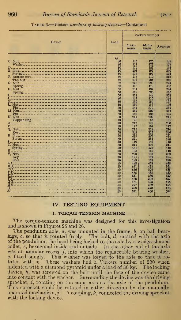
Table 3.
—
Vickers numbers of locking devices
Load
Vickers number
DeviceMaxi-mum
Mini-mum Average
I. American National coarse-thread regular nutkg
505050
5050
5050
503030303030
222208214
222208
214228
229174138191145191
205200209
205200
209217
222161132146129146
213II. U. S. standard regular nut 203
III. American National fine-thread regular nut 212IV. American National coarse-thread regular nut and a jam
nut .. 213V. U. S. standard regular nut and a jam nut 203VI. American National fine-thread regular nut and a jam
nut 212VII. U. S. standard slotted nut and a cotter pin 221VIII. American National fine-thread castellated nut and a
cotter pin 225A 167B, Nuty 135
Bolt 167B-U. S„ Nut .... 137
Bolt 167
960 Bureau of Standards Journal of Research
Table 3.
—
Vickers numbers of locking devices—Continued
[Vol. 7
Device
C, NutWasher
DE, Nut
SpringF, Bottom nut.
Top nutQ, Nut
SpringH, Nut
Spring
KL, Nut
PinM,Nut
PinN, Nut
Copper ringOPQ, Nut
KeyR, Nut
SpringST, Nut
SpringUV, Nut
KeyBolt
AABBCCDDEEFFGOHHII
JJ
Load
Vickers number
Maxi-mum
Mini-mum Average
kg30 145 125 13230 131 127 12930 176 157 16430 203 197 20050 516 497 50350 213 210 21250 213 204 21050 225 223 22450 492 479 48650 211 197 20450 679 536 65650 371 348 35830 147 116 13430 165 150 15730 160 157 15950 541 616 53150 212 209 21150 450 423 43550 214 209 21110 91 66 8130 212 192 20030 177 164 172
50 215 213 21450 328 325 32650 215 207 21150 571 254 46630 149 146 14850 214 207 21150 455 422 44230 166 115 14850 223 186 20930 195 169 18430 189 163 18050 488 458 46850 541 479 50460 546 526 53350 458 438 45050 541 536 53950 466 396 43750 454 423 44650 497 402 45850 488 470 47850 531 466 509
IV. TESTING EQUIPMENT
1. TORQUE-TENSION MACHINE
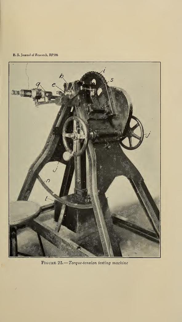
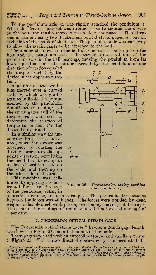
The torque-tension machine was designed for this investigationand is shown in Figures 25 and 26.
The pendulum axle, a, was mounted in the frame, b, on ball bear-ings, c, so that it rotated freely. The bolt, d, rotated with the axleof the pendulum, the head being locked to the axle by a wedge-shapedcollet, e, hexagonal inside and outside. In the other end of the axlewas an annular recess, /, into which the replaceable bearing washer,
g, fitted snugly. This washer was keyed to the axle so that it ro-
tated with it. These washers had a Vickers number of 200 whenindented with a diamond pyramid under a load of 30 kg. The lockingdevice, h, was screwed on the bolt until the face of the device cameinto contact with the washer. Surrounding the device was the drivingsprocket, i, rotating on the same axis as the axle of the pendulum.This sprocket could be rotated in either direction by the manuallyoperated mechanism,,;. A coupling, k, connected the driving sprocketwith the locking device.
B. S. Journal of Research, RP386
Figure 25.
—
Torque-tension testing machine
B. S. Journal of Research, RP386
Figure 27.
—
Tuckerman optical strain gages
mSm,e
seaquist\ Torque and Tension in Thread-Locking Devices 961
To the pendulum axle, a, was rigidly attached the pendulum, I.
When the driving sprocket was rotated so as to tighten the device
on the bolt, the tensile stress in the bolt, d, increased. This stress
was measured, using two Tuckerman optical strain gages, m, one oneach side of the shank of the bolt. The pendulum axle was cut awayto allow the strain gages to be attached to the bolt.
Tightening the device on the bolt also increased the torque on the
bolt and the pendulum axle. The torque caused rotation of the
pendulum axle in the ball bearings, moving the pendulum from its
lowest position until the torque exerted by the pendulum in onedirection of rotation equaledthe torque exerted by the C hdevice in the opposite direc-
tion.
A pointer on the pendu-lum moved over a curvedscale, n, which was gradu-ated to indicate the torqueexerted by the pendulum.Simultaneous readings of
the strain gages and of thetorque scale were used to
determine the relation of
torque to tension for thedevice being tested.
In a similar way the un-crewing torque was meas-ured, when the device wasloosened, by rotating thedriving sprocket in the op-posite direction, permittingthe pendulum to swing to
its lowest position, zero onthe scale, and then up onthe other side of the scale.
This machine was cali-
brated by applying two hor-
izontal forces to the axle
of the pendulum, acting in
Figure 26.
—
Torque-tension testing machine,schematic drawing
opposite directions, to form a couple. The perpendicular distancebetween the forces was 40 inches. The forces were applied by deadweight to flexible steel bands passing over pulleys having ball bearings.The error in the readings of the machine did not exceed one-half of
1 per cent.
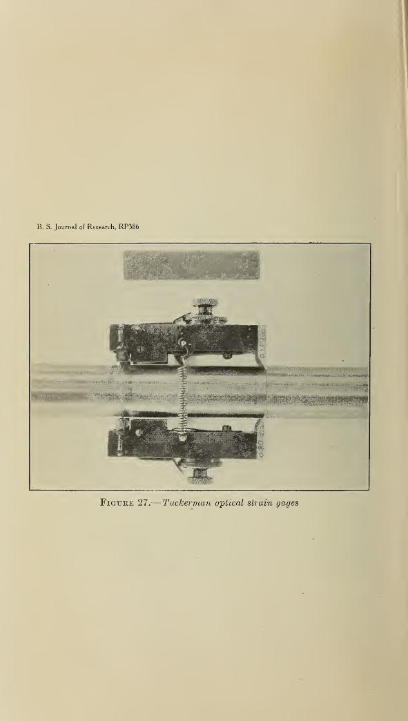
2. TUCKERMAN OPTICAL STRAIN GAGE
The Tuckerman optical strain gages, 11 having a 2-inch gage length,are shown in Figure 27, mounted on one of the bolts.
These gages are used with an autocollimator, q, and auxiliary prism,s, Figure 25. This autocollimated observing system permitted the
11 A description of the Tuckerman optical strain gage and autocollimated observing system will be foundin the Proceedings of the American Society for Testing Materials, vol. 23, 1923, Pt. II, technical papers,pp. 602-610; in Engineering, London, vol. 116, 1923, pp. 222-223; and in Paper No. 335, World EngineeringCongress, Tokyo, Japan, pp. 33-36, Precision Machines and Instruments for the Measurement of Length,by George K. Burgess.

962 Bureau of Standards Journal of Research [Vol. 7
strainm the bolt to be measured within one-millionth of an inch per
inch, corresponding to a stress in the body of the bolt of 29 lb. per
sq. in. The two strain gages and autocollimator were calibrated
with an interferometer.
As direct observation of the seating of the knife-edges and lozenges
of the strain gages in the grooves in the bolt was prevented by the
pendulum axle and the frame of the machine, a laryngoscope was usedto observe these contact points when the strain gages were put into
place. This instrument consisted of a periscope and a small electric
light adjacent to the reflecting prism of the periscope for illuminating
the field of vision.
V. PREPARATION OF SPECIMENS
To provide seats for the strain gages two grooves, 2 inches apart,were rolled in the shank of the bolt by means of the fixture shown in
Figure 28.
The upper section, a, of the fixture was hinged, allowing it to beswung back so that the bolt could be placed in the fixture. A spacingcollar, b, was placed on the bolt»to locate the grooves with respect to
the head of the bolt. As the bolt, supported on the rollers, c—c,
was manually rotated, force was gradually applied to the groovingrollers by screwing down the loading knob, d. Stops, e—e, controlledthe depth of the grooves by limiting the travel of the upper section.
The included angle of the groove nearest to the head of the bolt,
in which the knife edge rested, was 60°. The included angle of theother groove was 120°, so as to permit the lozenge of the strain gageto rotate slightly without touching the sides of the grooves.
VI. MEASURING SPECIMENS
1. GENERAL
Although variations in the dimensions of the threads, either on thebolt or in the nut, would be expected to affect to some extent thetorque-tension relationship, no method of measuring the errors inlead or of the thread contour was found which could be used on all
the devices.
The methods which are used for ordinary threads could not be usedfor the nuts and bolts having deformed threads; therefore the deviceshaving ordinary threads were not measured by the usual methods.Moreover, such measurements would have been tedious and ex-pensive.
As it was believed that differences in the dimensions of the threadssufficiently great to affect the torque-tension relationships would beindicated by measuring the diametral clearance between the nutand the bolt when assembled and the obliquity of the bearing face ofthe nut, these measurements were made on all ordinary nuts and onall the other devices on which it was practicable. These values wereused to determine whether the ordinary bolts and nuts complied withthe purchase specifications.
Each bolt and device was examined visually. None of the devicessubmitted by the manufacturers showed any defects. A few of theordinary nuts did not have full threads and were therefore discarded.

B. S. Journal of Research. RP386
Figure 28.
—
Fixture for grooving bolts
B. S. Journa of Research, RP386
Figtjke 29.
—
Fixture for measuring the obliquity of the face of the nut

WhittemoreNusbaum, Seaquistl Torque and Tension in Thread-Locking Devices 963
2. CLEARANCE BETWEEN THREADS OF NUT AND BOLT
The clearance between the threads in the nut and those on the boltwas measured by the fixture shown in Figure 24. The bolt wassecured in the fixture by the clamping plate, a, and thumbscrew, b.
The spindle of the dial micrometer rested on a corner of the nut di-
rectly over the axis of the bolt. A small upward force was appliedto the nut by the fingers while the nut was rotated back and forththrough a small angle, and the maximum reading recorded. Thisoperation was repeated with a small downward force applied to thenut. The difference between these two readings was taken as thediametral clearance between the nut and bolt. The results aregiven in Table 4.
Table 4.
—
Diametral clearance between threads of nut and bolt
DeviceMaxi-mum
Mini-mum Average
I. American National coarse-thread regular nutII. U. S. standard regular nutHI. American National fine-thread regular nutIV. American National coarse-thread regular nut and a jam nutV. U. S. standard regular nut and a jam nut
VI. American National fine-thread regular nut and a jam nutVII. U. S. standard slotted nut and a cotter pinVIII. American National fine-thread castellated nut and a cotter pin.AB.„.B-U.
D, deformed nut.E„__FGH._I
Inch0.0082.0079.0016.0082.0079.0016.0079.0016.0091
'
.0018!
.0010!
.0066 I
Inch0.0058.0060.0010.0058.0060.0010.0060.0010.0033.0008.0000.0038
JKL, pin prevented measurement.MNOPQ -
B,
STU
.0088
.0098
.0088,0101
,0062,0074,0100
.0030
.0050,0040.0059,0040,00360039
V, deformed threadAA to JJ, spring washers.
.0100
.0149
.0086
.0081
.0051
.0081,0080,00590072
,0079
.0048
.0027
.0033
.0017
.0016
.0049
.0024,0018,0000
0060
Inch0.0073.0069.0014.0073.0069.0014.0069.0014.0070.0012.0006.0050
.0068
.0074
.0057
.0076,0051,0055,0049
.0071
.0066
.0055
.0060
.0036
.0068,0051.0040,0027
0069
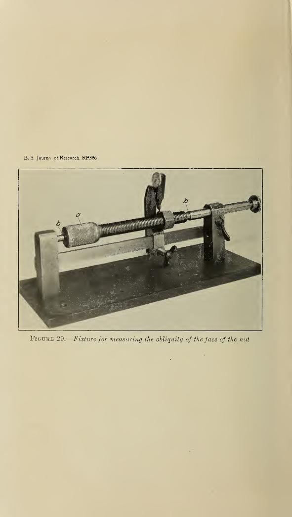
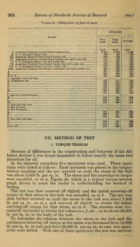
3. OBLIQUITY OF FACE OF NUT
The obliquity of the bearing faces of the nuts was measured, using
the fixture shown in Figure 29. Nuts having deformed threads andthose having certain locking features which interfered with the bolt
threads could not be measured, as they could not be screwed on the
mandrel.The mandrel was mounted between the centers, b—b, and the dial
micrometer adjusted to bring the spindle into contact with the bearingface of the nut, % inch from center. The mandrel was then rotated,
and the maximum and minimum readings of the dial recorded. Thedifference between these readings was taken as a measure of the
obliquity of the bearing face. If the difference was zero, the bearing
face was perpendicular to the axis of the nut. The values for eachdevice are given in Table 5.
964 Bureau of Standards Journav of Research
Table 5.
—
Obliquities of face of nuts
[VoL 7
Obliquities
DeviceMaxi-mum
Mini-mum Average
I American National coarse-thread regular nut..Inch0.014.010.030.016.012.009.010.009.015.006.007
Inch0.003.003.003.002.001.001.002.000.008.000.002
Inch0.009
II U. S. standard regular nut .0062i7 American National fine-thread regular nut .010IV. American National coarse-thread regular nut and a jam nutV. TJ. S. standard regular nut and a jam nut .
.009
.005VI. American National fine-thread regular nut and a jam nut .006
VII. TJ. S. standard slotted nut and a cotter pin .004VIII. American National fine-thread castellated nut and a cotter pinA — -
.005
.011
B — .003B-U. S - .005C, cast face; does not bearD, unfinished nut .028
.008
.005
.016
.030
.011
.011
.003
.002
.002
.004
.005
.020E .005F .003Q .007H .011I .007J, cast nut, face V shapedK .013
.029
.015
.001
.008
.009
.005L .017M .012N, face does not bear0, face beveledP, face V shapedQ .014
.006
.019
.002
.001
.004
.009B - .003S ._ .008T, face does not bearTJ. .010
.012
.010
.003
.005
.003
.006V. .008AAto JJ .006
VII. METHOD OF TEST
1. TORQUE-TENSION
Because of differences in the construction and behavior of the dif-
ferent devices it was found impossible to follow exactly the same test
procedure for all.
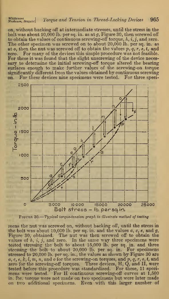
In the simplest procedure five specimens were used. Three speci-
mens were tested as follows : Each specimen was placed in the torque-tension machine and the nut screwed on until the stress in the boltwas about 5,000 lb. per sq. in. The stress and the screwing-on torquewere recorded, as at a, Figure 30, which is a typical torque-tensiongraph drawn to assist the reader in understanding the method of
testing.
The nut was then screwed off slightly and the initial screwing-offtorque at that stress in the bolt was recorded, as at 6. The nut wasthen further screwed on until the stress in the bolt was about 7,000lb. per sq. in., as at c, and screwed off slightly to obtain the initial
screwing-off torque for that stress, as at d. The stresses were suc-cessively increased to obtain the values at e,f, etc., up to about 20,000lb. per sq. in. in the body of the bolt.
To determine the relation between the stress in the bolt and thecontinuous screwing-off torque as the stress was decreased from 10,000lb. per sq. in. to zero and from 20,000 lb. per sq. in. to zero, two speci-mens were tested. With one of these specimens the nut was screwed
WhittemoTeNusbaum, Seaquist] Torque and Tension in Thread-Locking Devices 965
on, without backing off at intermediate stresses, until the stress in the
bolt was about 10,000 lb. per sq. in. as at g, Figure 30, then screwed off
to obtain the values of continuous screwing-off torque, h, i,j, and zero.
The other specimen was screwed on to about 20,000 lb. per sq. in. as
at o, then the nut was screwed off to obtain the values p, g, r, s, t, andzero. For many of the devices this simple procedure was not feasible.
For these it was found that the slight unscrewing of the device neces-
sary to determine the initial screwing-off torque altered the bearingsurfaces enough to make further values of the screwing-on torquesignificantly different from the values obtained by continuous screwingon. For these devices nine specimens were tested. For three speci-
2500
5 000 IOOOO 15000 20000 25000Bolt s+ress - lb. persqJn.
Figure 30.
—
Typical torque-tension graph to illustrate method of testing
mens the nut was screwed on, without backing off, until the stress in
the bolt was about 10,000 lb. per sq. in. and the values a, c, e, and g,
Figure 30, obtained. The nut was then screwed off to obtain the
values of h, i, j, and zero. In the same way three specimens weretested stressing the bolt to about 15,000 lb. per sq. in. and three
stressing the bolt to about 20,000 lb. per sq. in. For specimensstressed to 20,000 lb. per sq. in., the values as shown by Figure 30 are
a, c, e, k, I, m, n, and o for the screwing-on torques, and p } g, r, s, t, andzero for the screwing-off torques. Three devices, H, Q, and II, weretested before this procedure was standardized. For these, 11 speci-
mens were tested. For H continuous screwing-off curves at 1,500
in. lbs. torque were not made on two specimens^ but were later madeon two additional specimens. Even with this larger number of
966 Bureau of Standards Journal of Research [Vol. 7
specimens it was possible to determine the initial screwing-off torqueat only three different stresses. There seemed to be no need for
increasing this number further. For Q and II screwing-on and initial
screwing-off torques were measured on nine specimens. For the other
two, continuous screwing-off torques were determined.Where the locking device used two nuts, a further change in the test
procedure became necessary. Nine specimens were tested as before,
with the following modification. The first nut was screwed on, read-
ing the values of the screwing-on torque and stress as a, c, e, g, Figure
30, until the desired stress (10,000, 15,000, or 20,000 lb. per sq. in.)
was reached. The first nut was then held so that it did not turn on the
bolt and the jam nut screwed on with the required torque. In general,
this altered the tensile stress in the bolt, in some cases imperceptibly,
and in no case more than 2,000 lb. per sq. in. This altered stress wasrecorded as the stress corresponding to the initial screwing-off torque.
Where this change of stress was appreciable it is noted on the curvesby a bent arrow, as shown in Figure 30, connecting with the extrapoint p'.
The screwing-off torque was applied to the first nut only, and theinitial and continuous screwing-off torque read as before.
The ordinary jam nuts were screwed on with a torque equal to thetorque on the first (regular) nut, multiplied by the ratio of the thick-
ness of the two nuts. The special jam nuts of the proprietary devices
were applied as closely as possible, in conformity with the manufac-turers' instructions. The special jam nut of device F was appliedwith the same torque as the first nut.
Device I was screwed on hand-tight, then given a half turn with a
wrench; this did not noticeably increase the stress in the bolt. Thejam nut of device K was applied with a torque of 1,000 in. lb., as it
was found that this torque deformed the nut to the extent recom-mended by the manufacturer. The same modification ofprocedurewasnecessary for devices S and V since the carrying out of the lockingprocedure alters the stress in the bolt. For device Q the impact,caused by driving in the pin, displaced the strain gage so that thealteration of stress could not be directly determined. For the last
two specimens, which were screwed off to zero, the strain gages wereremoved while driving the pin, and then replaced, making possiblean indirect determination of the change.
In one case the stress increased 300 lb. per sq. in. and in the othercase decreased 2,000 lb. per sq. in. The initial screwing-off curvesare therefore plotted as if there had been no change in stress. Forall jam nuts (IV, V, VI, F, I, and K) and for devices Q and S, thescrewing-on torques recorded are the same as if no locking devicehad been used. The locking device affects only the screwing-offtorques.
In plotting all of these torque-tension curves large open circles
were used for screwing-on torques and large solid circles for theinitial screwing-off torques. For the continuous screwing-off torquessmall solid circles were used.A new bolt was used for each specimen, also a new regular nut,
if one was used with the device. The face of the bearing washer wasreground for each test, using a cylindrical grinder and a fine feed.The grinder marks were circular about the axis of the bolt, and thefaces were smooth, flat and parallel.

m l
Jba™m,e
seaquisi] Torque and Tension in Thread-Locking Devices 967
When the spring washers were tested, it was found that the con-tinuous screwing-off torque fluctuated considerably, caused probably,by the ends of the spring washers cutting into the bearing washerand into the nut, then releasing suddenly. This, however, did notprevent the use of the simplest test procedure except in the case ofdevice II.
For device II these fluctuations in the torque displaced the strain
gages making it impossible to obtain satisfactory readings of thestress in the bolt when the nut was unscrewed. Consequently, thesecond procedure with 11 specimens was used for this device.
Each locking device, bolt, and bearing washer was first thoroughlycleaned in carbon tetrachloride and then flushed with a good gradeof light mineral machine oil before it was placed in the torque-tensionmachine. The relation between the viscosity and temperature ofthe oil is shown in Figure 31.
The bolt was placed in the axle of the pendulum and the headwedged so that it rotated with the pendulum. The strain gageswere placed on the bolt and seated in the grooves. The device wasscrewed on the bolt and coupled to the driving sprocket. As thesprocket was rotated to screw the nut on the bolt the strain in thebolt increased.
To determine the stress in the bolt from the strain, the averagestrain was multiplied by the average Young's modulus of elasticity
28,900,000 lb. per sq. in.
2. DEFLECTION OF SPRING WASHERS
The relation between the compressive forces and the deflections
of the spring washers was determined in a universal testing machine.Three specimens of each locking device were taken at random. Eachspecimen was placed on a bolt between two hardened collars, and the
bolt was then loaded in tension. A dial micrometer was adjustedso that the spindle rested on the upper end of the bolt. Simul-taneous readings of load and deflection were recorded until the
spring washer was flat. Then the load was decreased and readings
of load and deflection recorded until the load was again zero. Eachspecimen was loaded repeatedly in this way until the behavior of the
specimen did not change appreciably, many of them being loadedfive or six times.
VIII. RESULTS
The results obtained in the torque-tension machine are showngraphically in Figures 32 to 72, inclusive. The number of specimenstested (5, 9, or 11) indicates the particular test procedure used. Thecoordinates of each point on these graphs are the averages of the stress
and torque values obtained on all specimens tested in the same way.The stresses are in all cases the averages of the tensile stresses in the
bodies of the bolts. To obtain the stress in the bolt at the root of
the American National coarse and U. S. standard thread or at the
pitch line of the thread, the stresses given must be multiplied by 1.46
and 1.20, respectively. The stresses shown for the American Na-tional fine thread, Figures 34, 37, and 39, must be multiplied by 1.12
and 1.06 to find the stresses at the root and at the pitch line of the
threads, respectively.
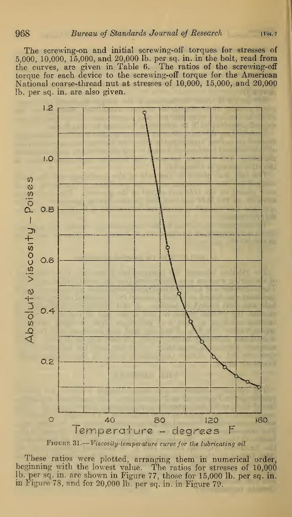
968 Bureau of Standards Journal oj Research [Vol. 7
The screwing-on and initial screwing-off torques for stresses of
5,000, 10,000, 15,000, and 20,000 lb. per sq. in. in the bolt, read fromthe curves, are given in Table 6. The ratios of the screwing-off
torque for each device to the screwing-off torque for the AmericanNational coarse-thread nut at stresses of 10,000, 15,000, and 20,000
lb. per sq. in. are also given.
1.2
1.0
(0
OCl 0.8
3 0.8
i °-4
<
0.2
\
\ ta
i ,I ,
i^\_
1
_5^
O 40 80 120 J60
Temperature - degrees FFigure 31.
—
Viscosity-temperature curve for the lubricating oil
These ratios were plotted, arranging them in numerical order,beginning with the lowest value. The ratios for stresses of 10,000lb. per sq. in. are shown in Figure 77, those for 15,000 lb. per sq. in.
in Figure 78, and for 20,000 lb. per sq. in. in Figure 79.
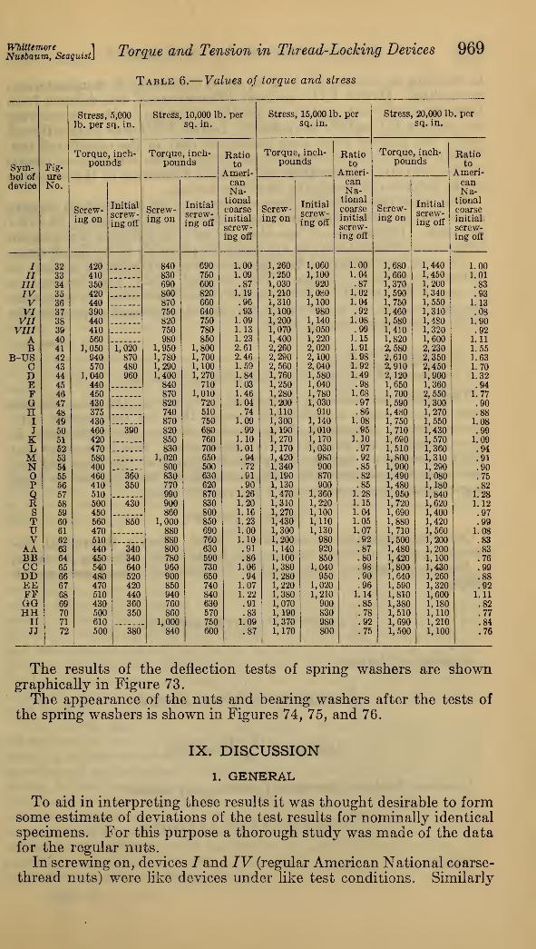
msbaum'seaquist] Torque and Tension in Thread-Locking Devices 969
Table 6.— Values of torque and stress
Stress, 5,000 Stress, 10,000 It». per Stress, 15,000 It . per Stress, 20,000 It . per
lb. per sq. in. sq. in. sq. in. sq. in.
Torque, inch- Torque , inch- Batio Torque, inch- Batio Torque, inch- Batio
Sym-bol of
device
Fig-pounds pounds to
Ameri-
pounds toAmeri-
pounds toAmeri-
ureNo. can
Na-canNa-
canNa-
Screw-ing on
Initial
screw-ing ofi
Screw-ing on
Initial
screw-ing on*
tionalcoarseinitial
screw-ing off
Screw-ing on
Initial
screw-ing ofi
tional
coarseinitial
screw-ing off
Screw-ing on
Initial
screw-ing off
tionalcoarseinitial
screw-ing off
I 32 420 840 690 1.00 1,260 1,060 1.00 1,680 1,440 1.00
II 33 410 830 750 1.09 1,250 1,100 1.04 1,660|
1,450 1.01
III 34 350 690 600 .87 1,030 920 .87 1,370 1,200 .83IV 35 420 800 820 1.19 1,210 1,080 1.02 1,590 1,340 .93V 36 440 870 660 .96 1, 310 1,100 1.04 1,750 1,550 1.13VI 37 390 750 640 .93 1,100 980 .92 1,460 1,310 .08VII 38 440 820 750 1.09 1,200 1,140 1.08 1,580 1,480 1.90VIII 39 410 750 780 1.13 1,070 1,050 .99 1,410 1, 320 .92A 40 560 980 850 1.23 1,400 1,220 1.15 1,820 1,600 1.11
B 41 1,050 1,020 1,950 1,800 2.61 2,260 2,020 1.91 2,580 2,230 1.55
B-US 42 940 870 1,780 1,700 2.46 2,290 2,100 1.98 2,610 2,350 1.63
C 43 570 480 1,290 1,100 1.59 2,560 2,040 1.92 2,910 2,450 1.70D 44 1,040 960 1,400 1,270 1.84 1,760 1,580 1.49 2,120 1,900 1.32E 45 440 840 710 1.03 1,250 1,040 .98 1,650 1,360 .94F 46 450 870 1,010 1.46 1,280 1,780 1.68 1,700 2,550 1.77G 47 430 820 720 1.04 1,200 1,030 .97 1,590 1, 300 .90H 48 375 740 510 .74 1,110 910 .86 1,480 1,270 .88I 49 430 870 750 1.09 1,300 1,140 1.08 1,750 1,550 1.08J 50 460 390 820 680 .99 1,190 1,010 .95 1,710 1,430 .99K 51 420 850 760 1.10 1,270 1,170 1.10 1,690 1,570 1.09L 62 470 830 700 1.01 1,170 1,030 .97 1,510 1,360 .94
M 53 580 1,020 650 .94 1,420 980 .92 1,800 1,310 .91
N 54 400 800 500 .72 1,340 900 .85 1,900 1,290 .9055 460 360 830 630 .91 1,190 870 .82 1,490 1,080 .75
P 56 410 350 770 620 .90 1,130 900 .85 1,480 1,180 .82
Q 57 510 990 870 1.26 1,470 1,360 1.28 1,950 1,840 1.28R 58 500 430 900 830 1.20 1,310 1,220 1.15 1,720 1,620 1.12S 59 450 860 800 1.16 1,270 1,100 1.04 1,690 1,400 .97T 60 560 850 1,000 850 1.23 1,430 1,110 1.05 1,880 1,420 .99U 61 470 880 690 1.00 1,300 1,130 1.07 1,710 1,560 1.08V 62 510 880 760 1.10 1,200 980 .92 1,500 1,200 .83AA 63 440 340 800 630 .91 1,140 920 .87 1,480 1,200 .83BB 64 450 340 780 590 .86 1,100 850 .80 1,420 1,100 .76CC 65 540 640 960 730 1.06 1,380 1,040 .98 1,800 1,430 .99DD 66 480 520 900 650 .94 1,280 950 .90 1,640 1,260 .88EE 67 470 420 850 740 1.07 1,220 1,020 .96 1,590 1,320 .92FF 68 510 440 940 840 1.22 1,380 1,210 1.14 1,810 1,600 1.11GG 69 430 360 760 630 .91 1,070 900 .85 1,380 1,180 .82HH 70 500 350 860 570 .83 1,190 830 .78 1,510 1,110 .77
II 71 610 1,000 750 1.09 1,370 980 .92 1,690 1,210 .84JJ 72 500 380 840 600 .87 1,170 800 .75 1,500 1,100 .76
The results of the deflection tests of spring washers are showngraphically in Figure 73.
The appearance of the nuts and bearing washers after the tests of
the spring washers is shown in Figures 74, 75, and 76.
IX. DISCUSSION
1. GENERAL
To aid in interpreting these results it was thought desirable to formsome estimate of deviations of the test results for nominally identical
specimens. For this purpose a thorough study was made of the datafor the regular nuts.
Inscrewing on, devices / and IV (regular American National coarse-thread nuts) were like devices under like test conditions. Similarly
970 Bureau oj Standards Journal of Research [Vot. 7
in screwing on, devices 77, V, I, K, and S (regular U. S. standard nuts)
were alike. Device V77 was from different stock, but differed fromthese nominally only in the slot for the cotter pin. Also, in screwingon, devices 777 and VI were alike. Device VIII was from different
stock, but differed from these nominally only in the castellated top.
Within each of these groups the deviation of the screwing-on torqueof the individual device from the mean is a measure of the variation
in the behavior of nominally identical devices.
The maximum deviation from the mean of the screwing-on torquesin any one of these groups for stresses above 10,000 lb. per sq. in. is 6.1
per cent. Differences of less than 6 per cent between screwing-ontorques for different devices are therefore probably of no significance.
No such large group of like specimens was available for a study of
initial serewing-off torques. The detailed study was confined to
devices 7, 77, and 777. Between individual specimens the maximumdeviations from the mean which were found, expressed as percentagesof the screwing-on torque, were:
Per cent
Screwing-on torque ; 6Initial screwing-off torque 6Difference between screwing-on and screwing-off torques 5
The differences between individual specimens of the other deviceswere in most cases considerably greater than for the regular nuts.Consequently, differences of less than 6 per cent, or even more, inthese quantities are probably of no significance. It is to be noted thatif the screwing-on and the screwing-off torques on the same nut andbolt were independent the differences should be expected to showlarger deviations, approaching 9 per cent in value.
2. PERSY'S THEORY
Omitting negligible second-order terms, Persy's theoretical dis-
cussion applied to %-inch regular nuts leads to the following relations:
American National coarse and U. S. standard thread screwing-ontorque
^= 0.442 B/' + 0.175/+ 0.00703
Screwing-off torque
|=0.442 #/' + 0.175/-0.00703
Difference^"^
=0.0141o
American National fine-thread screwing-on torque
T^ = 0.442 Rf' + 0.181 /+ 0.00439
Nmbaum,e
seaquist] Torque and Tension in Thread-Locking Devices 971
Screwing-off torque
1+0.442 Rf' + 0.181 /- 0.00439
Difference ^-^ = 0.00879
where T = serewing-on torque (in. lb.).
t = screwing-off torque (in. lb.).
S= stress in bolt (lb. per sq. in.).
R = effective bearing radius of nut on washer (in.).
/' = coefficient of friction of nut on washer./= coefficient of friction of nut threads on bolt threads.
In these expressions three quantities, R,f, and/, occur, which areknown to vary considerably with small changes in the bearing sur-
faces, such as smoothness of finish, lubrication, etc.
In view of the variations found in the experiments between nomi-nally identical devices, no close check of these formulae could beexpected. They can, however, serve in some cases to give a generalidea of the behavior of regular nuts and bolts.
3. CLEARANCES AND OBLIQUITY OF BEARING FACE OF NUT
Detailed studies were made of the individual test results fromregular nuts. The scatter diagrams plotted showed a wholly randomdistribution. Within the limits used in these tests, neither clearanceof nut on bolt nor obliquity of the bearing face of the nut measurablyaffected the torques.
4. DEVICES
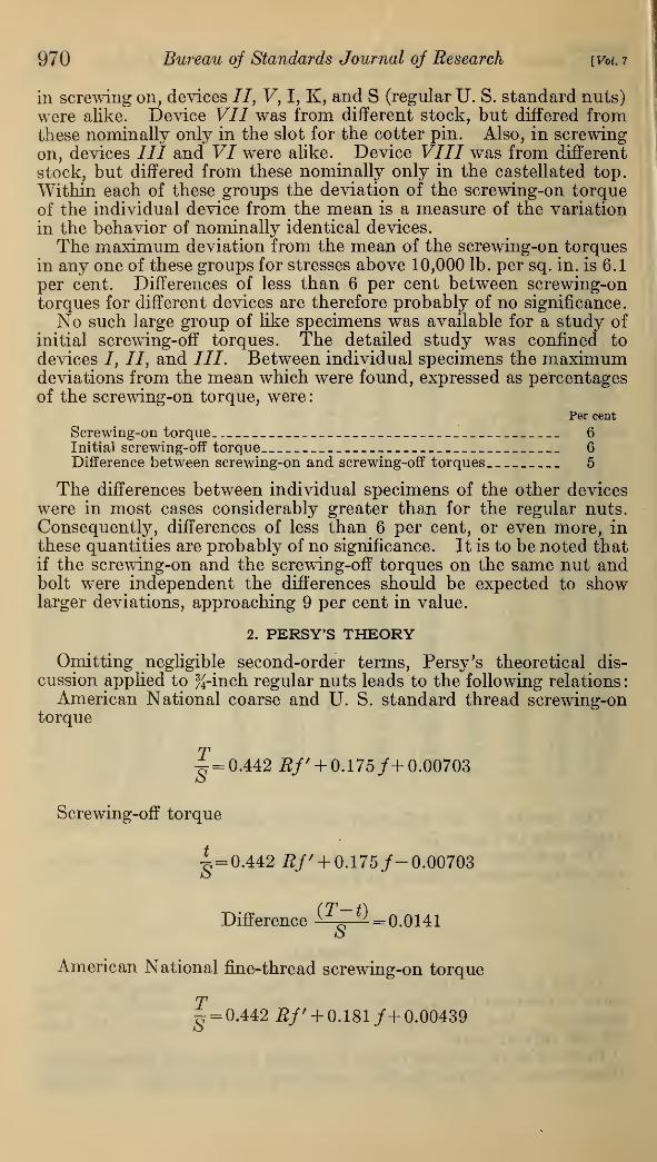
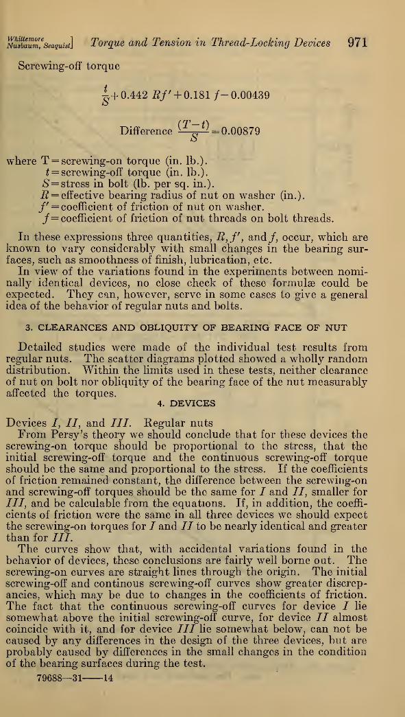
Devices /, //, and III. Regular nutsFrom Persy's theory we should conclude that for these devices the
screwing-on torque should be proportional to the stress, that theinitial screwing-off torque and the continuous screwing-off torqueshould be the same and proportional to the stress. If the coefficients
of friction remained constant, the difference between the screwing-onand screwing-off torques should be the same for / and II, smaller for
III, and be calculable from the equations. If, in addition, the coeffi-
cients of friction were the same in all three devices we should expectthe screwing-on torques for / and II to be nearly identical and greaterthan for III.The curves show that, with accidental variations found in the
behavior of devices, these conclusions are fairly well borne out. Thescrewing-on curves are straight lines through the origin. The initial
screwing-off and continous screwing-off curves show greater discrep-
ancies, which may be due to changes in the coefficients of friction.
The fact that the continuous screwing-off curves for device I lie
somewhat above the initial screwing-off curve, for device // almostcoincide with it, and for device III lie somewhat below, can not becaused, by any differences in the design of the three devices, but are
probably caused by differences in the small changes in the condition
of the bearing surfaces during the test.
79688—31 14
972 Bureau of Standards Journal of Research 1 Vol. 7
5000 10000 15 000 20 000 25000Bol+ stress - lb. per sq. in!
Figure 32.
—
Torque-tension curves for device I. American Nationalcoarse-thread regular nut. Five specimens were tested
pnnn
_ri >c gfij /'
1
•"V /"~N
3'
W^y£(2
inoo //' i
r•
'SOO'j&^
n
5000 10000 15 000 20000 25000bolt stress -!b. persq.in.
Figure 33.
—
Torque-tension curves for device II. U. S. standard regularnut. Five specimens were tested
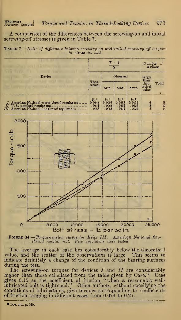
msbaum'seaquist] Torque and Tension in Thread-Locking Devices 973
A comparison of the differences between the screwing-on and initial
screwing-off stresses is given in Table 7.
Table 7.
—
Ratio of difference between screwing-on and initial screwing-off torques
to stress in bolt
T—tS
Number ofreadings
Device
Theo-retical
Observed Larger|
than i
Min. Max. Aver.
theo-retical
value
Total
I
7. American National coarse-thread regular nut77. TJ. S. standard regular nut
In*0. 0141.0141.0088
In.*
0.0094.0066.0053
In*0.0188.0152.0112
In*0. 0132.0098.0079
63
3
18
17
777. American National fine-thread regular nut 14
2000
i.
cI
0)
Or
1500
IO0O
500
'"bre
Igml
s*y
r •'S"
^HMSl=T
S
<^fr
^&&
^\in
O 5 000 I0OOO 15000 20000 25 000Bolt stress - lb. po,r sq.in.
Figure 34.—Torque-tension curves for device III. American National fine-
thread regular nut. Five specimens were tested
The average in each case lies considerably below the theoretical
value, and the scatter of the observations is large. This seems to
indicate definitely a change of the condition of the bearing surfacesduring the test.
The screwing-on torques for devices / and II are considerablyhigher than those calculated from the table given by Case. 12 Casegives 0.15 as the coefficient of friction "when a reasonably well-
lubricated bolt is tightened." Other authors, without specifying theconditions of lubrications, give torques corresponding to coefficients
of friction ranging in different cases from 0.074 to 0.21.
" Loc. cit., p. 920.
974 Bureau of Standards Journal of Research [Vol. 7
On the assumption that/=/'; that is, that the coefficient of friction
between nut and bolt is the same as between nut and washer, the
average value of/ was calculated by Persy's theory from the screwing-
on torques at 20,000 lbs. per sq. in. stress. The values were: Fordevice 7,/=0.20; for device II, f=0.19; and for device III, f=0.17.
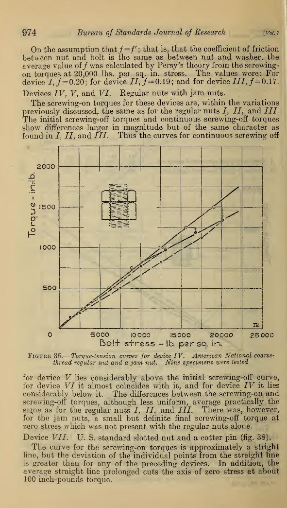
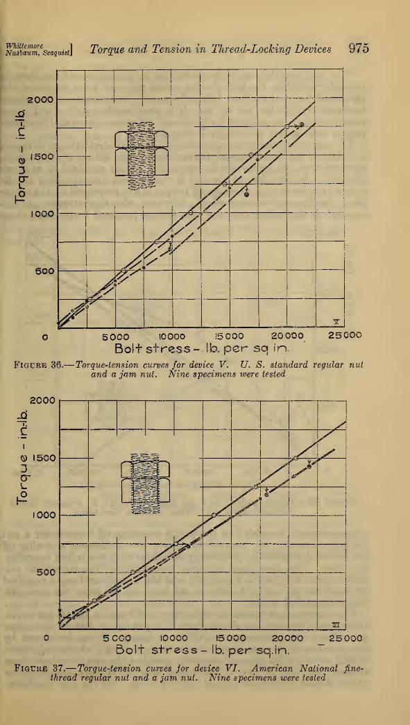
Devices IV, V, and VI. Regular nuts with jam nuts.
The screwing-on torques for these devices are, within the variations
previously discussed, the same as for the regular nuts /, II, and ///.
The initial screwing-off torques and continuous screwing-off torques
show differences larger in magnitude but of the same character as
found in /, II, and III. Thus the curves for continuous screwing off
5000 I0OOO 15000 20000 25 000E>ol+ stress -lb. psrsa. in.
Figure 35.
—
Torque-tension curves for device IV. American National coarse-
thread regular nut and a jam nut. Nine specimens were tested
for device V lies considerably above the initial screwing-off curve,
for device VI it almost coincides with it, and for device IV it lies
considerably below it. The differences between the screwing-on andscrewing-off torques, although less uniform, average practically the
same as for the regular nuts I, II, and ///. There was, however,for the jam nuts, a small but definite final screwing-off torque at
zero stress which was not present with the regular nuts alone.
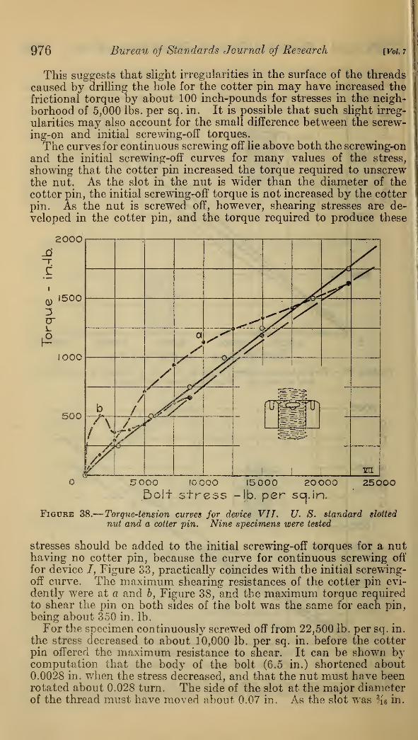
Device VII. U. S. standard slotted nut and a cotter pin (fig. 38).
The curve for the screwing-on torques is approximately a stright
line, but the deviation of the individual points from the straight line
is greater than for any of the preceding devices. In addition, theaverage straight line prolonged cuts the axis of zero stress at about100 inch-pounds torque.
WhittemoreNusbaum, Seaquist Torque and Tension in TJiread-Locking Devices 975
2000
i.
©3
1500
1000
500
-—
Y>J> j<~^§£^^" ">
/ s
'/
AsVA4A
($<*
/
j^<y/
y^\&S9
/ >
-z
5000 tOOOO 15 000 20 000 25000
Bolt stress- !b. per sq in.
Figure 36.— Torque-tension curves for device V. U. S. standard regular nutand a jam nut. Nine specimens were tested
2000
i.
CI
© 15003D"
1000
500
y.yy
r
fill %HSU & *
(yrj
y^
i
Y\%[
m5 COO I00C0 15 000 20000Bolt stress - lb. per sq.in.
25 000
Figure 37.
—
Torque-tension curves jor device VI. American National fine-
thread regular nut and a jam nut. Nine specimens were tested
976 Bureau of Standards Journal of Research [Vol. 7
This suggests that slight irregularities in the surface of the threads
caused by drilling the hole for the cotter pin may have increased the
friction al torque by about 100 inch-pounds for stresses in the neigh-
borhood of 5,000 lbs. per sq. in. It is possible that such slight irreg-
ularities may also account for the small difference between the screw-
ing-on and initial serewing-off torques.
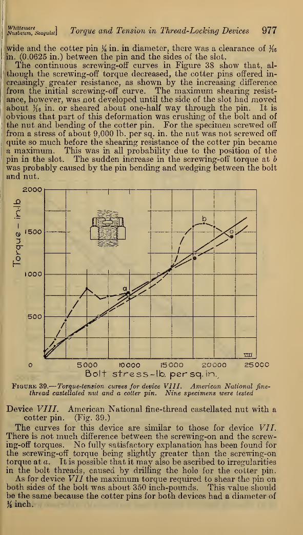
The curves for continuous screwing off lie above both the screwing-on
and the initial serewing-off curves for many values of the stress,
showing that the cotter pin increased the torque required to unscrewthe nut. As the slot in the nut is wider than the diameter of the
cotter pin, the initial screwing-off torque is not increased by the cotter
pin. As the nut is screwed off, however, shearing stresses are de-
veloped in the cotter pin, and the torque required to produce these
2000
0)1500
1000
500
5000 I0C00 15000 2OOO0bolt stress -lb. per scj.in.
25000
Figure 38.
—
Torque-tension curves for device VII. U. S. standard slotted
nut and a cotter pin. Nine specimens were tested
stresses should be added to the initial screwing-off torques for a nuthaving no cotter pin, because the curve for continuous screwing off
for device /, Figure 33, practically coincides with the initial screwing-off curve. The maximum shearing resistances of the cotter pin evi-
dently were at a and 6, Figure 38, and the maximum torque requiredto shear the pin on both sides of the bolt was the same for each pin,
being about 350 in. lb.
For the specimen continuously screwed off from 22,500 lb. per sq. in.
the stress decreased to about 10,000 lb. per sq. in. before the cotterpin offered the maximum resistance to shear. It can be shown bjT
computation that the body of the bolt (6.5 in.) shortened about0.0028 in. when the stress decreased, and that the nut must have beenrotated about 0.028 turn. The side of the slot at the major diameterof the thread must have moved about. 0.07 in. As the slot was %« in.
WhittemoreNu8baum, Seaguist Torque and Tension in Thread-Locking Devices 977
wide and the cotter pin % in. in diameter, there was a clearance of #6in. (0.0625 in.) between the pin and the sides of the slot.
The continuous screwing-off curves in Figure 38 show that, al-
though the screwing-off torque decreased, the cotter pins offered in-
creasingly greater resistance, as shown by the increasing difference
from the initial screwing-off curve. The maximum shearing resist-
ance, however, was not developed until the side of the slot had movedabout %e in. or sheared about one-half way through the pin. It is
obvious that part of this deformation was crushing of the bolt and of
the nut and bending of the cotter pin. For the specimen screwed off
from a stress of about 9,000 lb. per sq. in. the nut was not screwed off
quite so much before the shearing resistance of the cotter pin becamea maximum. This was in all probability due to the position of thepin in the slot. The sudden increase in the screwing-off torque at b
was probably caused by the pin bending and wedging between the bolt
and nut.
aooo
5000 I0OOO 15000 20000 25000Bolt stress-lb. per sq. in.,
Figure 39.
—
Torque-tension curves for device VIII. American National fine-thread castellated nut and a cotter pin. Nine specimens were tested
Device VIII. American National fine-thread castellated nut with acotter pin. (Fig. 39.)
The curves for this device are similar to those for device VII.There is not much difference between the screwing-on and the screw-ing-off torques. No fully satisfactory explanation has been found for
the screwing-off torque being slightly greater than the screwing-ontorque at a. It is possible that it may also be ascribed to irregularities
in the bolt threads, caused by drilling the hole for the cotter pin.
As iqr device VII the maximum torque required to shear the pin onboth sides of the bolt was about 350 inch-pounds. This value shouldbe the same because the cotter pins for both devices had a diameter of
}i inch.
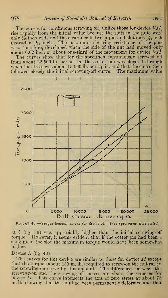
978 Bureau oj Standadrs Journal of Research [Vol. 7
The curves for continuous screwing off, unlike those for device VII,
rise rapidly from the initial value because the slots in the nuts wereonly %2 inch wide and the clearance between pin and slot only K 2 inch
instead of #e inch. The maximum shearing resistance of the pins
was, therefore, developed when the side of the nut had moved only
about 0.02 inch or about one-third of the movement for device VII.The curves show that for the specimen continuously screwed off
from about 22,500 lb. per sq. in. the cotter pin was sheared throughwhen the stress was about 15,000 lb. per sq. in. and that the curve then
followed closely the initial screwing-off curve. The maximum value
2500/*
2000
q) 15003cr
tooo
500
5000 10000 15 000 20 000 25000Boli stress - lb. per sq. in.
Figure 40.
—
Torque-tension curves for device A. Five specimens were tested
at b (fig. 39) was appreciably higher than the initial screwing-off
torque. However, it seems evident that if the cotter pin had been asnug fit in the slot the maximum torque would have been somewhathigher.
Device A (fig. 40).
The curves for this device are similar to those for device II exceptthat the torque (about 150 in. lb.) required to screw-on the nut raisedthe serewing-on curve by this amount. The differences between thescrewing-on and the screwing-off curves are about the same as fordevice //. This curve intersects the axis of zero stress at about 75in. lb. showing that the nut had been permanently deformed and that
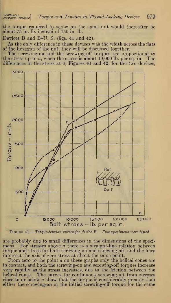
WhittemoreNusbaum, Seaquist Torque and Tension in Thread-Locking Devices 979
the torque required to screw on the same nut would thereafter beabout 75 in. lb. instead of 150 in. lb.
Devices B and B-U. S. (figs. 41 and 42).
As the only difference in these devices was the width across the flats
of the hexagon of the nut, they will be discussed together.
The screwing-on and the screwing-off torques are proportional to
the stress up to a, when the stress is about 10,000 lb. per sq. in. Thedifferences in the stress at a, Figures 41 and 42, for the two devices,
Figure 41.-
5 000 I0OOO 15000 20 000Bolt stress — lb. per sq. in.
Torque-tension curves for device B. Five specimens were tested
are probably due to small differences in the dimensions of the speci-
mens. For stresses above a there is a straight-line relation betweentorque and stress for both screwing on and screwing off, and the lines
intersect the axis of zero stress at about the same point.
From zero to the point a on these graphs only the helical cones are
in contact, and both the screwing-on and screwing-off torques increase
very rapidly as the stress increases, due to the friction between thehelical cones. The curves for continuous screwing off from stresses
close to or below a show that the torque is considerably greater thaneither the screwing-on or the initial screwing-off torque for the same
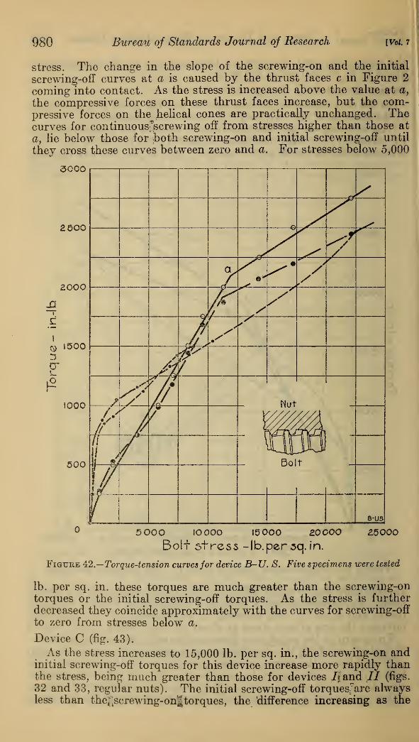
980 Bureau of Standards Journal of Research [Vol. 7
stress. The change in the slope of the serewing-on and the initial
serewing-off curves at a is caused by the thrust faces c in Figure 2
coming into contact. As the stress is increased above the value at a,
the compressive forces on these thrust faces increase, but the com-pressive forces on the helical cones are practically unchanged. Thecurves for continuous^screwing off from stresses higher than those at
a, lie below those for both screwing-on and initial screwing-off until
they cross these curves between zero and a. For stresses below 5,000
3000
5O0O IOOOO 15 000 20000 £5000
Bolt stress -Ib.persq. in.
Figure 42.—Torque-tension curves for device B-U. S. Five specimens were tested
lb. per sq. in. these torques are much greater than the screwing-ontorques or the initial screwing-off torques. As the stress is furtherdecreased they coincide approximately with the curves for screwing-off
to zero from stresses below a.
Device C (fig. 43).
As the stress increases to 15,000 lb. per sq. in., the screwing-on andinitial screwing-off torques for this device increase more rapidly thanthe stress, being much greater than those for devices It and // (figs.
32 and 33, regular nuts). The initial screwing-off torquesjare alwaysless than the^screwing-on|torques, the 'difference increasing as the
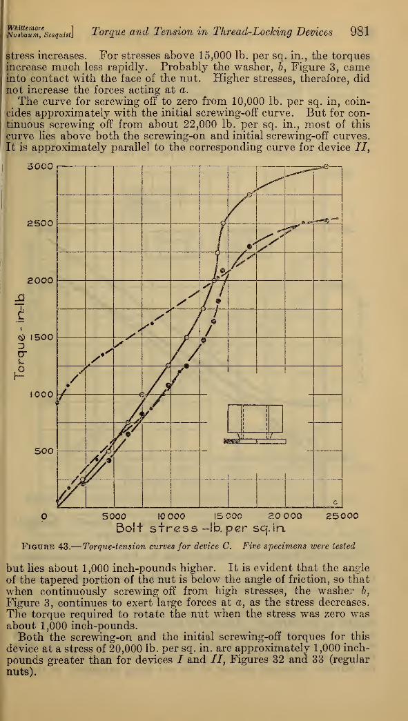
WhittemoreNusbaum, Seaquist.] Torque and Tension in Thread-Locking Devices 981
stress increases. For stresses above 15,000 lb. per sq. in., the torquesincrease much less rapidly. Probably the washer, 6, Figure 3, cameinto contact with the face of the nut. Higher stresses, therefore, didnot increase the forces acting at a.
The curve for screwing off to zero from 10,000 lb. per sq. in, coin-
cides approximately with the initial serewing-off curve. But for con-tinuous screwing off from about 22,000 lb. per sq. in., most of this
curve lies above both the serewing-on and initial serewing-off curves.
It is approximately parallel to the corresponding curve for device 77,
3000
2500
2000
«
<$ 1500
cr
£1000
500
O 5000 10 000 15 000 20 000 25000Bolt stress -lb. per scj.in.
Figure 43.
—
Torque-tension curves for device C. Five specimens were tested
but lies about 1,000 inch-pounds higher. It is evident that the angle
of the tapered portion of the nut is below the angle of friction, so that
when continuously screwing off from high stresses, the washer h,
Figure 3, continues to exert large forces at a, as the stress decreases.
The torque required to rotate the nut when the stress was zero wasabout 1,000 inch-pounds.Both the serewing-on and the initial serewing-off torques for this
device at a stress of 20,000 lb. per sq. in. are approximately 1,000 inch-
pounds greater than for devices J and 77", Figures 32 and 33 (regular
nuts).
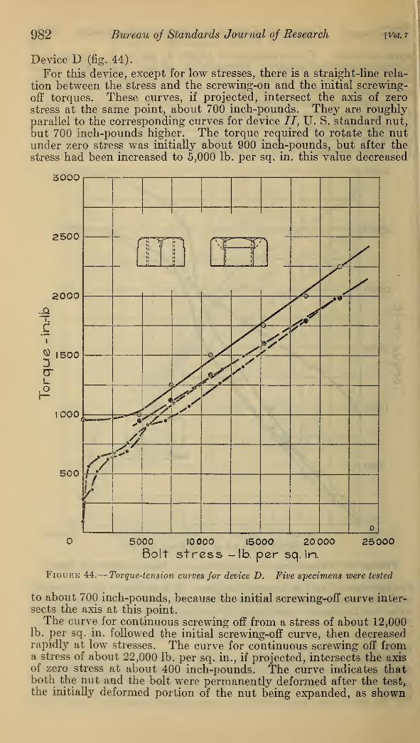
982 Bureau oj Standards Journal of Research [Vol. 7
Device D (fig. 44).
For this device, except for low stresses, there is a straight-line rela-
tion between the stress and the screwing-on and the initial screwing-
off torques. These curves, if projected, intersect the axis of zero
stress at the same point, about 700 inch-pounds. They are roughlyparallel to the corresponding curves for device II, U. S. standard nut,
but 700 inch-pounds higher. The torque required to rotate the nutunder zero stress was initially about 900 inch-pounds, but after the
stress had been increased to 5,000 lb. per sq. in. this value decreased
3000
O 5000 I000O 15000 20 000 25000Bolt stress -lb. per sq. in.
Figure 44.
—
Torque-tension curves for device D. Five specimens were tested
to about 700 inch-pounds, because the initial screwing-off curve inter-
sects the axis at this point.The curve for continuous screwing off from a stress of about 12,000
lb. per sq. in. followed the initial screwing-off curve, then decreasedrapidly at low stresses. The curve for continuous screwing off froma stress of about 22,000 lb. per sq. in., if projected, intersects the axisof zero stress at about 400 inch-pounds. The curve indicates thatboth the nut and the bolt were permanently deformed after the test,
the initially deformed portion of the nut being expanded, as shown

WhittemoreNusbaum, Seaquist] Torque and Tension in Thread-Locking Devices 983
by the lower intercept, and the bolt becoming somewhat tapered, as
shown by the rapid decrease of the torque near zero stress. This
interpretation was confirmed by supplementary measurements ob-
tained by screwing the device on and off an unstressed bolt.
3000
2500
2000
I.
C
® 1500
1000
500
fe]S"\
<r
•A <
K yy
if
ISAyy
s
y 'Vy 1
Ay r
AyE
5 000 10 000 15000 20000. 25000Bolt s+ress-!b. per sq. in.
Figure 45.
—
Torque-tension curves for device E. Nine specimens were tested
Device E (fig. 45).
The curves for this device are about the same as those for devices
I and II, Figures 32 and 33 (regular nuts). The screwing-on and the
initial screwing-off torques are approximately proportional to the
stress.
The end b of the spring, Figure 5, was deformed when the device
was unscrewed. It could not be used again.
Device F (fig. 46).
The screwing-on torques for this device, as should be expected,
were proportional to the stress and the values the same as for those
of devices I and 77, Figures 32 and 33 (regular nuts). The initial
screwing-off torques are considerably greater than the screwing-on
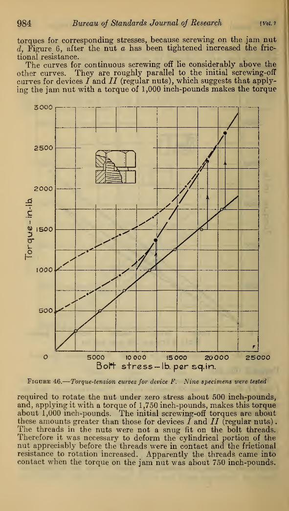
984 Bureau of Standards Journal of Research [Vol. i
torques for corresponding stresses, because screwing on the jam nut
d, Figure 6, after the nut a has been tightened increased the fric-
tional resistance.
The curves for continuous screwing off lie considerably above the
other curves. They are roughly parallel to the initial screwing-off
curves for devices / and II (regular nuts), which suggests that apply-
ing the jam nut with a torque of 1,000 inch-pounds makes the torque
3000
5000 10 000 15 000 20 000 25000Boh" stress — lb. per sq.in.
Figure 46.
—
Torque-tension curves for device F. Nine specimens were tested
required to rotate the nut under zero stress about 500 inch-pounds,and, applying it with a torque of 1,750 inch-pounds, makes this torqueabout 1,000 inch-pounds. The initial screwing-off torques are aboutthese amounts greater than those for devices i" and II (regular nuts)
.
The threads in the nuts were not a snug fit on the bolt threads.Therefore it was necessary to deform the cylindrical portion of thenut appreciably before the threads were in contact and the frictional
resistance to rotation increased. Apparently the threads came intocontact when the torque on the jam nut was about 750 inch-pounds.
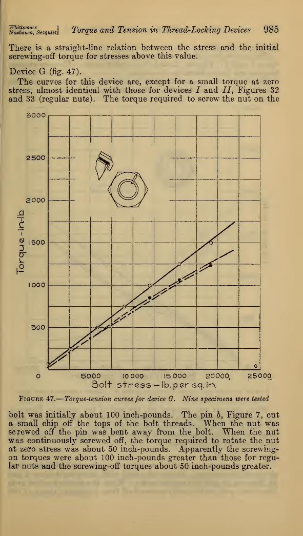
Whittemore 1
Nusbaum, Seaquistl Torque and Tension in Thread-Locking Devices 985
There is a straight-line relation between the stress and the initial
screwing-off torque for stresses above this value.
Device G (fig. 47).
The curves for this device are, except for a small torque at zero
stress, almost identical with those for devices / and II, Figures 32and 33 (regular nuts). The torque required to screw the nut on the
3000
O 5000 10 000 15 000 20000, 25000Bolt stress —lb. per scj. in.
Figure 47.
—
Torque-tension curves for device G. Nine specimens were tested
bolt was initially about 100 inch-pounds. The pin 6, Figure 7, cuta small chip off the tops of the bolt threads. When the nut wasscrewed off the pin was bent away from the bolt. When the nutwas continuously screwed off, the torque required to rotate the nutat zero stress was about 50 inch-pounds. Apparently the screwing-on torques were about 100 inch-pounds greater than those for regu-lar nuts and the screwing-off torques about 50 inch-pounds greater.
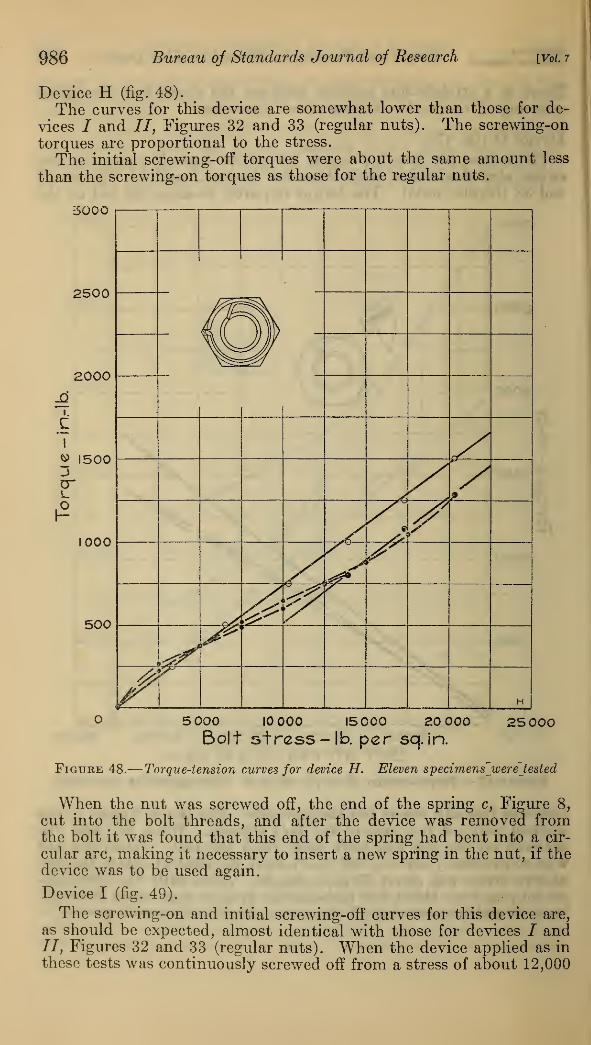
986 Bureau of Standards Journal oj Research [Vol. 7
Device H (fig. 48).
The curves for this device are somewhat lower than those for de-
vices i" and II, Figures 32 and 33 (regular nuts). The screwing-on
torques are proportional to the stress.
The initial screwing-off torques were about the same amount less
than the screwing-on torques as those for the regular nuts.
5000
2500
2000
I.
Ci
^ 15003cr
1000
500
5 000 10 000 15000 20 000
Bolt stress -lb. per sq. in.
25 000
Figure 48.
—
Torque-tension curves for device H. Eleven specimens"were' tested
When the nut was screwed off, the end of the spring c, Figure 8,
cut into the bolt threads, and after the device was removed fromthe bolt it was found that this end of the spring had bent into a cir-
cular arc, making it necessary to insert a new spring in the nut, if thedevice was to be used again.
Device I (fig. 49).
The screwing-on and initial screwing-off curves for this device are,
as should be expected, almost identical with those for devices / and//, Figures 32 and 33 (regular nuts). When the device applied as in
these tests was continuously screwed off from a stress of about 12,000
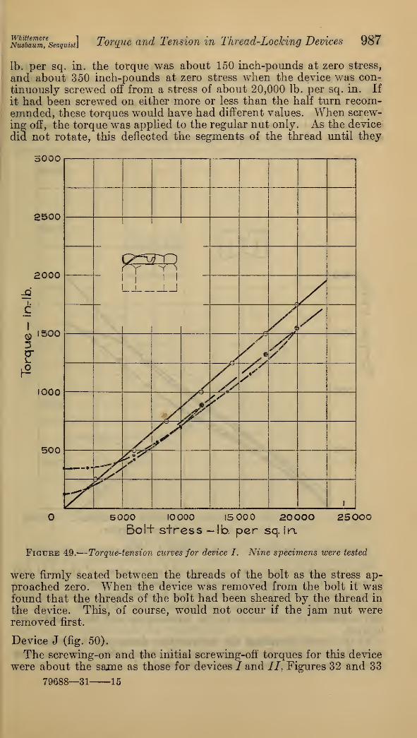
WhittemoreNusbaum, Seaquist Torque and Tension in Thread-Locking Devices 987
lb. per sq. in. the torque was about 150 inch-pounds at zero stress,
and about 350 inch-pounds at zero stress when the device was con-
tinuously screwed off from a stress of about 20,000 lb. per sq. in. If
it had been screwed on either more or less than the half turn recom-emnded, these torques would have had different values. When screw-
ing off, the torque was applied to the regular nut only. As the device
did not rotate, this deflected the segments of the thread until they
3000
2500
2000
i.
c
9 500
1000
500
ry ^ S
i
!_J LJ
S J.//€$f
^r
ydL&$r.
— —«P^
"/^i
5000 10000 15 00 200OOBol+ stress -lb. per sq. in.
25000
Figure 49.
—
Torque-tension curves for device I. Nine specimens were tested
were firmly seated between the threads of the bolt as the stress ap-
proached zero. When the device was removed from the bolt it wasfound that the threads of the bolt had been sheared by the thread in
the device. This, of course, would not occur if the jam nut wereremoved first.
Device J (fig. 50).
The screwing-on and the initial screwing-off torques for this devicewere about the same as those for devices / and II, Figures 32 and 33
79688—31 15
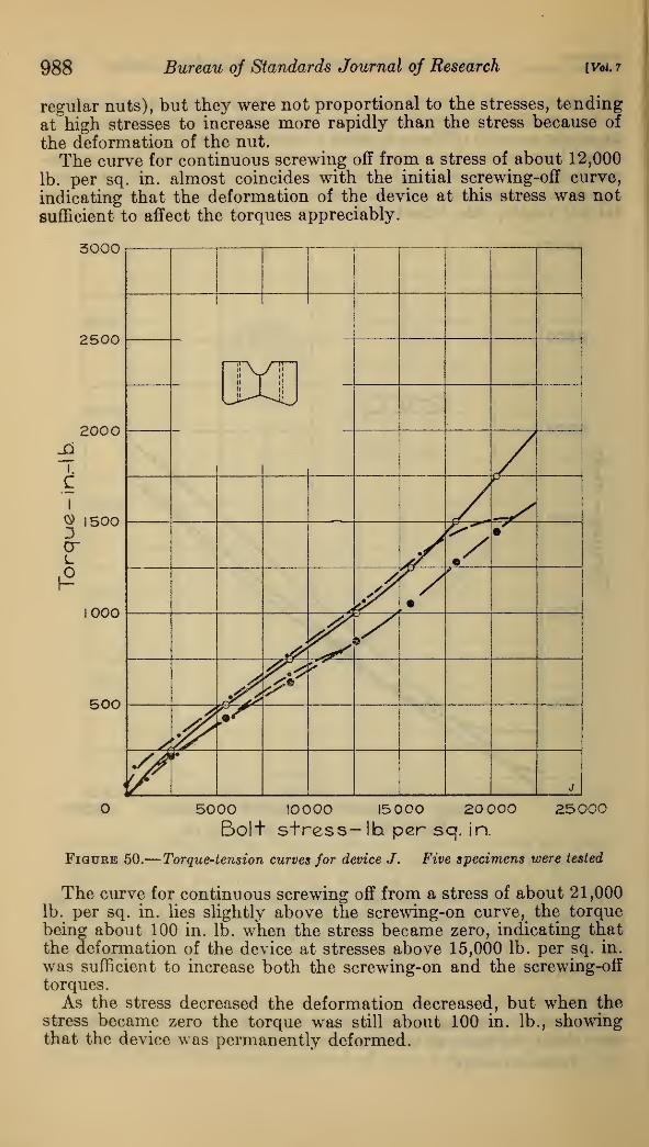
988 Bureau of Standards Journal of Research [Vol. 7
regular nuts), but they were not proportional to the stresses, tending
at high stresses to increase more rapidly than the stress because of
the deformation of the nut.
The curve for continuous screwing off from a stress of about 12,000
lb. per sq. in. almost coincides with the initial screwing-off curve,
indicating that the deformation of the device at this stress was not
sufficient to affect the torques appreciably.
3000
2500
200Oj3
i.
C
0) 15003cr
1000
500
1 1
I
t
"iPyT"
S*jf 7 •
•
f
V
?'
A?&j
5000 10000 15 000 20 000 25000Bolt stress- lh per sq. in.
Figure 50.
—
Torque-tension curves for device J. Five specimens were tested
The curve for continuous screwing off from a stress of about 21,000lb. per sq. in. lies slightly above the screwing-on curve, the torquebeing about 100 in. lb. when the stress became zero, indicating thatthe deformation of the device at stresses above 15,000 lb. per sq. in.
was sufficient to increase both the screwing-on and the screwing-off
torques.
As the stress decreased the deformation decreased, but when thestress became zero the torque was still about 100 in. lb., showingthat the device was permanently deformed.
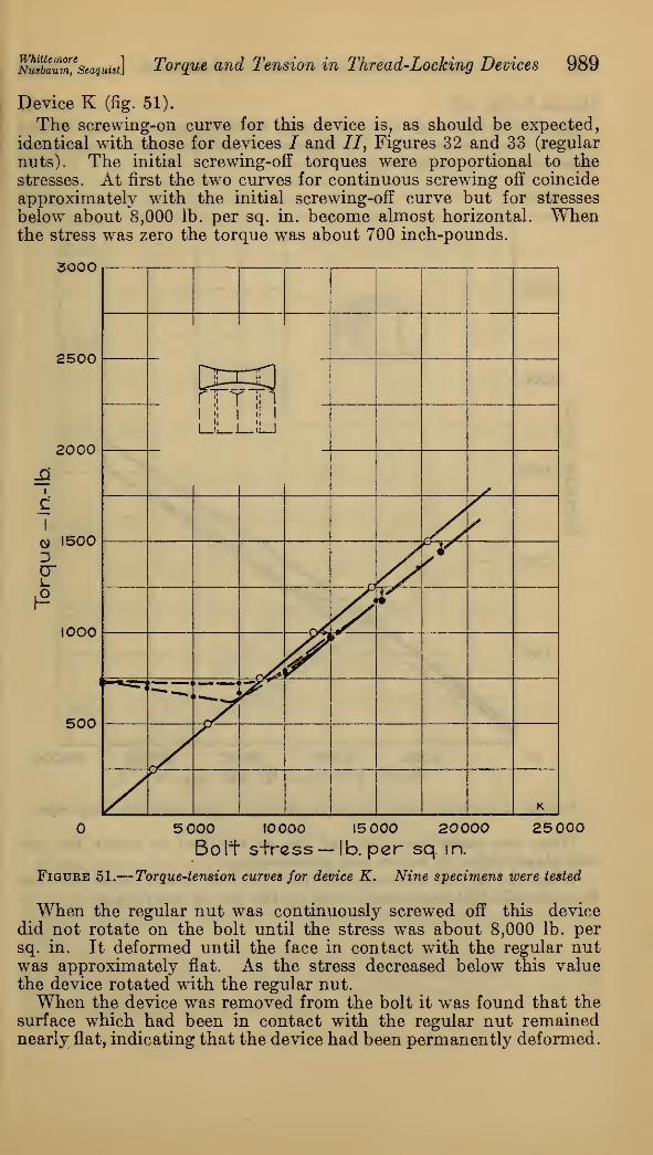
WhittemoreNusbaum, Seaquist] Torque and Tension in Thread-Locking Devices 989
Device K (fig. 51).
The screwing-on curve for this device is, as should be expected,
identical with those for devices / and //, Figures 32 and 33 (regular
nuts). The initial screwing-off torques were proportional to the
stresses. At first the two curves for continuous screwing off coincide
approximately with the initial screwing-off curve but for stresses
below about 8,000 lb. per sq. in. become almost horizontal. Whenthe stress was zero the torque was about 700 inch-pounds.
3000
2500
2000
i
9 15003cr
1000
500
*1rnHi
'
1L_iL_i_!i_J
d\Sf
//J*
ir
»(
"*"*<
i i
» ,<
K
5 000 10000 15 000 20000 25 000
Boll" s+rcss—-lb. per sq. in.
Figure 51.
—
Torque-tension curves for device K. Nine specimens were tested
When the regular nut was continuously screwed off this devicedid not rotate on the bolt until the stress was about 8,000 lb. persq. in. It deformed until the face in contact with the regular nutwas approximately flat. As the stress decreased below this valuethe device rotated with the regular nut.When the device was removed from the bolt it was found that the
surface which had been in contact with the regular nut remainednearly flat, indicating that the device had been permanently deformed.

990 Bureau of Standards Journal of Research [Vol. 7
Device L (fig. 52).
Except for the small torques at zero stress these curves are similar
to those for devices / and II, Figures 32 and 33 (regular nuts), butshow somewhat lower torques.
300Q
2500
2000
I.
£TG> 15003crL.
I
2
1000
500
fSS^/" *N1 1-
i
U
tr^ -X
^!>
i
>
£&*\
JJ&
jTr
L
O 5000 10 000 15000 20 000 25000Bolt stress -lb. per sq. in.
Figure 52.
—
Torque-tension curves for device L. Nine specimens were tested
When the stress was zero the torque required to rotate the nutwas about 50 in. lb. before and after testing.
When the device was removed from the bolt it was found that thebolt threads had been roughened by the pin in the device.

WhittemoTeNusbaum, Seaquist. Torque and Tension in Thread-Locking Devices 991
Device M (fig. 53).
At a stress of about 22,000 lb. per sq. in. the screwing-on torque
for this device was the same as those for devices I and II, Figures 32
and 33 (regular nuts), but for most stresses between this value andzero the screwing-on torque was about 150 inch-pounds greater.
The initial screwing-off torques at about 20,000 lb. per sq. in.
were about 100 inch-pounds lower than those for regular nuts, the
3000
2500
2000
JO».
cI
O 15003cr
1000
500
S N
Iy
y9
,s
f
tS-(0^
—7^'£'
>
M
5000 10000 15000 20000 25000Bolt stress -lb. per sq. in.
Figure 53.
—
Torque-tension curves for device M. Nine specimens were tested
torque being proportional to the stress. The continuous screwing-off
torques lie slightly above the initial screwing-off torque curve ex-
tended.When this device was removed from the bolt it was found that the
pin in the device had cut into the face of the bearing washer. Chipsfilled the space around the pin. It would be necessary to removethem before using the device again.

992 Bureau oj Standards Journal oj Research [Vol. ?
Device N (fig. 54).
The screwing-on torques for this device were almost the same as
those for devices J and //, Figures 32 and 33 (regular nuts), up to astress of about 13,000 lb. per sq. in. Above this value these torquesincreased more rapidly as the stress increases.
The initial screwing-ofT torques were about 150 inch-pounds less
than those for regular nuts, but the torques for continuous screwing
3COO
5000 10 000 15000 20 000 25000Boli. stress - lb. per sq.in.
Figure 54.
—
Torque-tension curves for device N. Nine specimens were tested
off were only slightly less. When continuously screwed off from astress of 20,000 lb. per sq. in. the torque at zero stress was about 100inch-pounds.When the device was removed from the bolt the ring usually re-
mained on the bolt. To remove it the ends of the strip forming thering were pried apart with a screw driver. A new copper ring wouldbe needed each time the device was used.

WhlttemoreNusbaum, Seaquist Torque and Tension in Thread-Locking Devices 993
Device O (fig. 55).
The screwing-on torques for this device are slightly greater thanthose for devices J and II, Figures 32 and 33 (regular nuts), up to
about 10,000 lb. per sq. in. For higher stresses they increase less
rapidly, until at 20,000 lb. per sq. in. stress they are lower than for
devices I and 77.
5000
2500
2000
c\
3crLo
500
000
500
5000. 10 000 15 000 20 000Bolt stress — ib. persq.in.
25OO0
Figure 55.
—
Torque-tension curves for device 0. Five specimens were tested
For high stresses the initial serewing-off torques are considerablyless than those for regular nuts.
In continuous screwing off there is still a torque at zero stress,
indicating that the device has been permanently deformed after it hasbeen stressed as high as 10,000 lb. per sq. in.
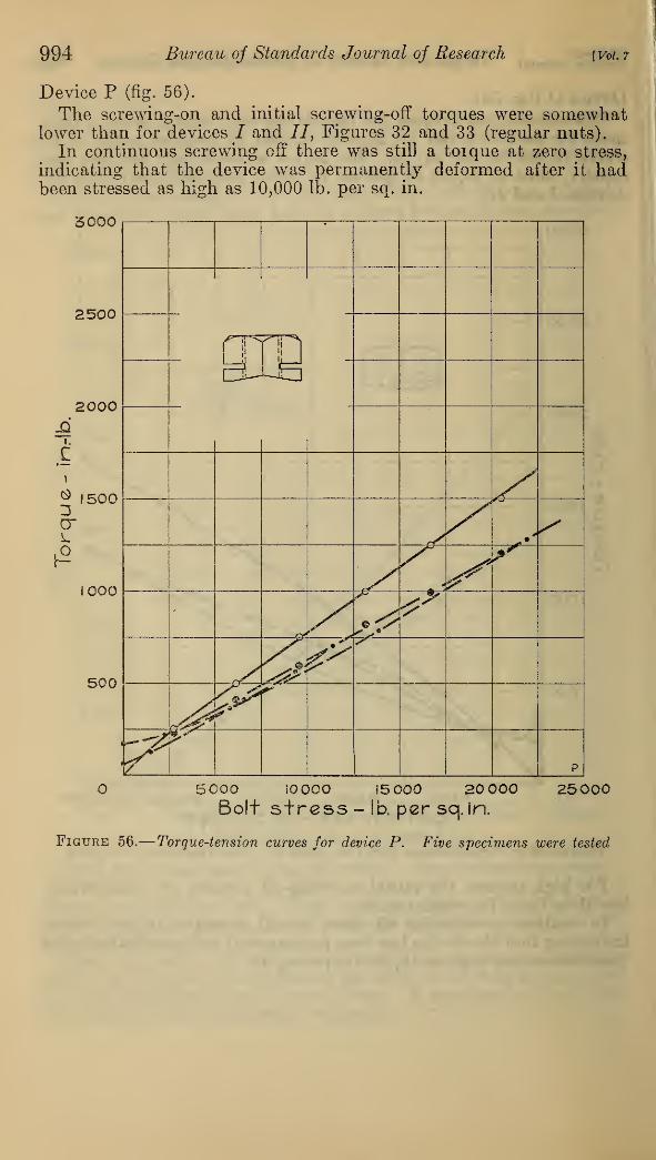
994 Bureau oj Standards Journal of Research [Vol. 7
Device P (fig. 56).
The screwing-on and initial screwing-off torques were somewhatlower than for devices / and //, Figures 32 and 33 (regular nuts).
In continuous screwing off there was still a toique at zero stress,
indicating that the device was permanently deformed after it hadbeen stressed as high as 10,000 lb. per sq. in.
5C00
O 5000 iOOOO !5 000 20 000 25000Bolt stress - lb. per sq. in.
Figure 56.
—
Torque-tension curves for device P. Five specimens were tested
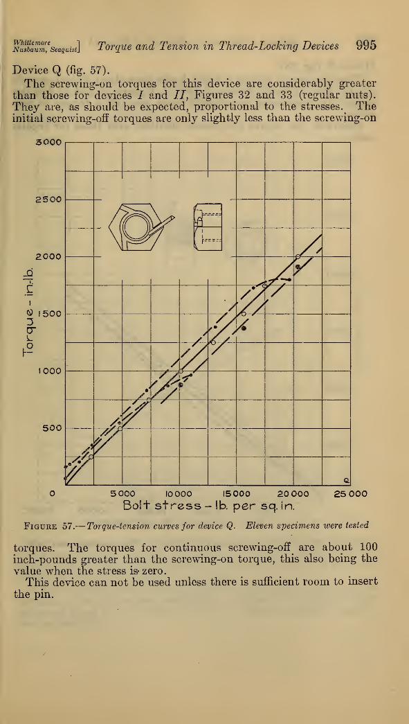
WhittemoreNusbaum, Seaquist] Torque and Tension in Thread-Locking Devices 995
Device Q (fig. 57).
The screwing-on torques for this device are considerably greater
than those for devices I and II, Figures32 and 33 (regular nuts).
They are, as should be expected, proportional to the stresses. ^ Theinitial screwing-off torques are only slightly less than the screwing-on
3000
O 5 000 10 000 15000 20 000 25 000Bolt stress - lb. per sq. in.
Figure 57.
—
Torque-tension curves for device Q. Eleven specimens were tested
torques. The torques for continuous screwing-off are about 100
inch-pounds greater than the screwing-on torque, this also being the
value when the stress is- zero.
This device can not be used unless there is sufficient room to insert
the pin.
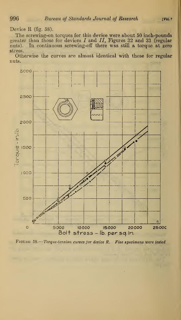
996 Bureau oj Standards Journal oj Research [Vol, 7
Device R (fig. 58).
The screwing-on torques for this device were about 50 inch-poundsgreater than those for devices / and II, Figures 32 and 33 (regular
nuts). In continuous screwing-off there was still a torque at zerostress.
Otherwise the curves are almost identical with those for regular
nuts.
5000
2500
200O
c
O 1500
crLO
000
500 -
5000 10000 15000 20000 2500CBolt stress - lb. per sq. in.
Figure 58.
—
Torque-tension curves Jor device R. Five specimens were tested
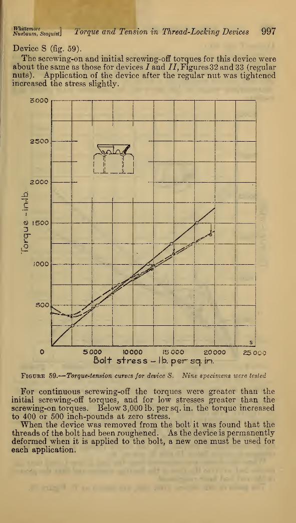
WhittemoreNuabaum, SeaquiBt} Torque and Tension in Thread-Locking Devices 997
Device S (fig. 59).
The screwing-on and initial screwing-off torques for this device wereabout the same as those for devices I and II, Figures 32 and 33 (regularnuts). Application of the device after the regular nut was tightenedincreased the stress slightly.
5000
2500
2000
I.
cI
O !500
cr
.o
1000
500
i
i
rri'1 ll !L_
•i
1
i >•
r^^i^r
! 1
i
r
^ i
|
i
i
s
5 000 10000 i5C00 20000Soit stress - lb. per sq. in.
£5 00«
Figure 59.
—
Torque-tension curves for device S. Nine specimens were tested
For continuous screwing-off the torques were greater than the
initial screwing-off torques, and for low stresses greater than the
screwing-on torques. Below 3,000 lb. per sq. in. the torque increased
to 400 or 500 inch-pounds at zero stress.
When the device was removed from the bolt it was found that the
threads of the bolt had been roughened. As the device is permanentlydeformed when it is applied to the bolt, a new one must be used for
each application.
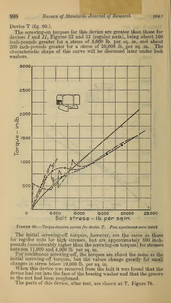
998 Bureau of Standards Journal of Research [Vol. 7
Device T (fig. 60.).
The screwing-on torques for this device are greater than those for
devices / and II, Figures 32 and 33 (regular nuts), being about 100
inch-pounds greater for a stress of 5,000 lb. per sq. in. and about200 inch-pounds greater for a stress of 20,000 lb. per sq. in. Thecharacteristic shape of this curve will be discussed later under lock
washers.
sooo
5 000 I00OO 15000 20000BoJf stress - lb. per sq.in.
25000
Figure 60.— Torque-tension curves for device T. Five specimens* were tested
The initial serewing-off torques, however, are the same as thosefor regular nuts for high stresses, but are approximately 800 inch-pounds (considerably higher than the screwing-on torques) for stressesbetween 11,000 and 4,000 lb. per sq. in.
For continuous screwing-off, the torques are about the same as theinitial screwing-off torques, but the values change greatly for smallchanges in stress below 10,000 lb. per sq. in.
When this device was removed from the bolt it was found that thedevice had cut into the face of the bearing washer and that the groovein the nut had been roughened.The parts of this device, after test, are shown at T, Figure 76.
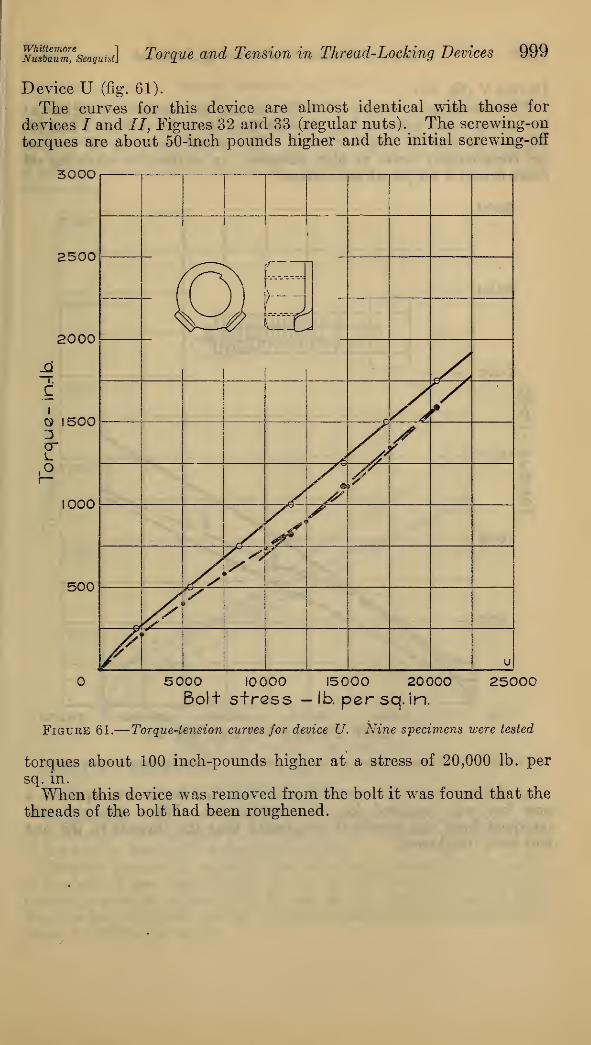
NSaum,e
seaguist] Torque and Tension in Thread-Locking Devices 999
Device U (fig. 61).
The curves for this device are almost identical with those for
devices I and 77, Figures 32 and 33 (regular nuts). The screwing-on
torques are about 50-inch pounds higher and the initial screwing-off
300O
5000 10000 15000 20000Bolt stress — lb. per sq. in.
2500C
Figure 61.
—
Torque-tension curves for device U. Nine specimens were tested
torques about 100 inch-pounds higher at a stress of 20,000 lb. per
sq. in.
When this device was removed from the bolt it was found that the
threads of the bolt had been roughened.
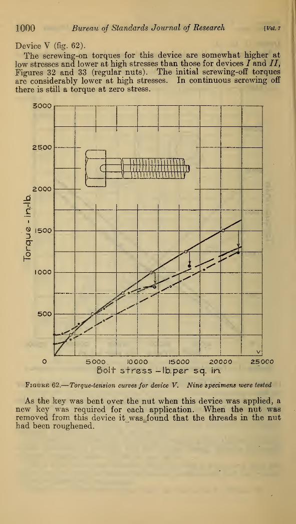
1000 Bureau of Standards Journal of Research [Vol. 7
Device V (fig. 62).
The screwing-on torques for this device are somewhat higher at
low stresses and lower at high stresses than those for devices I and 77,
Figures 32 and 33 (regular nuts). The initial screwing-off torques
are considerably lower at high stresses. In continuous screwing off
there is still a torque at zero stress.
3000
5000 10000 15000 20000 25000Bolt stress -lb. per sq. in.
Figure 62.
—
Torque-tension curves for device V. Nine specimens were tested
As the key was bent over the nut when this device was applied, a
new key was required for each application. When the nut wasremoved from this device itjw&sjound that the threads in the nuthad been roughened.

mltouZ'seaquist] Torque and Tension in Thread-Locking Devices 1001
Devices AA to JJ. Spring washers (figs. 63-72).
The screwing-on curves for the spring washers show a characteristic
difference from the curves for regular nuts (/, II, and III).
The screwing-on torques, instead of being proportional to the stress,
at first rise more rapidly, and in the majority of the cases approacha straight line which intersects the axis of zero stress at some point
above zero.
3000
2500
2000
I.
QI
cr
(2
500
1000
500
5 000 10000 15000 20000Bolt stress- lb. per sq. in.
25 000
Figure 63.
—
Torque-tension curves for device AA, spring washer. Five spec-
imens were tested
Comparison with the load-deflection curves, Figure 73, shows that
in most cases the straight portion of the curve begins approximatelyat the load at which the washer became flat.
Thus for device EE, which is flat at loads corresponding to a stress
in the bolt of less than 2,000 lb. per sq. in., the curve for screwing-on
torque is straight above 5,000 lb. per sq. in., while for device DD,which is flat at 6,000 lb. per sq. in. stress, the curve is not straight until
about 10,000 lb. per sq. in.
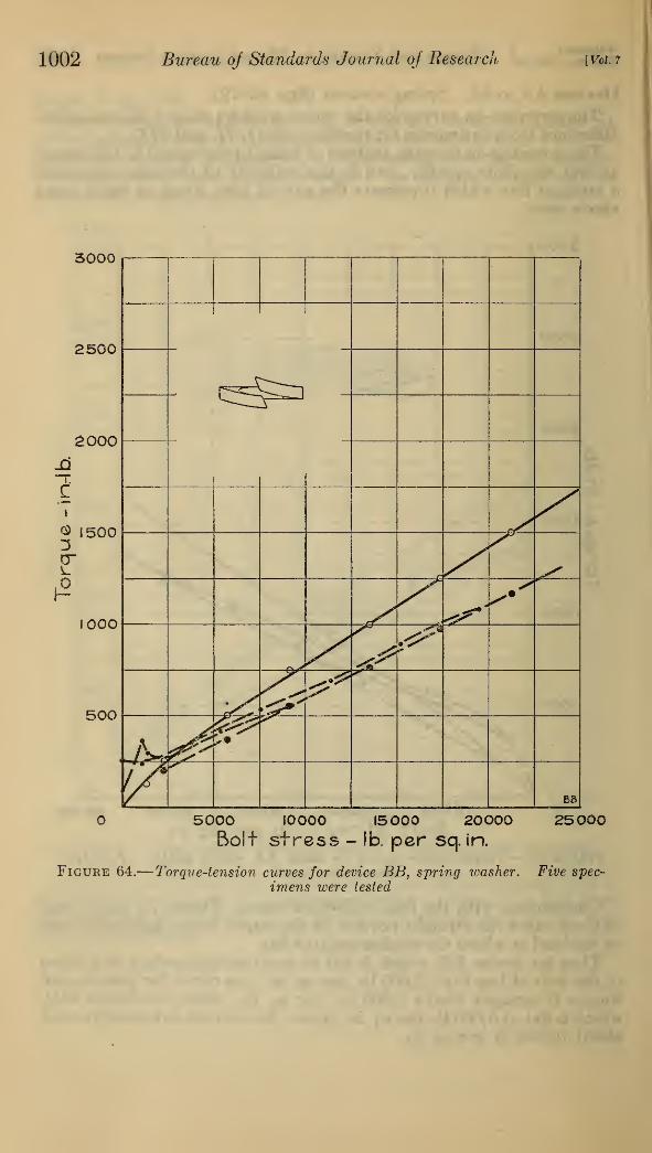
1002 Bureau of Standards Journal of Research [Vol. 7
3000
2500
2000
C
® 1500
£1000
500
1 1
L ^^
j X""
-^*-^
"*"
r/^-^^^•^ ^' s*
kv
X^
\y^
EB
5000 10000 15000 20000Bolt stress - lb. per sq. in.
25000
Figure 64.— Torque-tension curves for device BB, spring washer. Five spec-
imens were tested
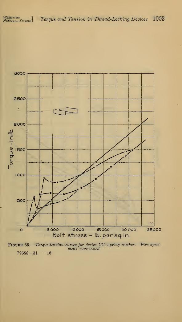
mfbauZ'seaquist] Torque and Tension in Thread-Locking Devices 1003
3000
2500
2000
® 1500
L
1000
500
£5&
5 000 iOOOO 15000 20 000
Bolt stress - lb. per sq. in.
25000
Figure 65.
—
Torque-tension curves for device CC, spring washer. Five speci-
mens were tested
79688—31 16
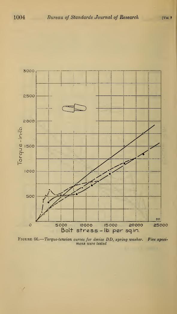
1004 Bureau of Standards Journal of Research [Vol.?
30C0
:500
2000
i.
C
® 1500Dcr
1000
500
!
SX X
•'&<^
:^>'>•
^
ffifls>
>•
/XDD
5000 10000 15000 20000Bolt stress - lb. per sq.in.
25000
Figure 66.
—
Torque-tension curves for device DD, spring washer. Five speci-
mens were tested

mlfaumfseaquist] Torque and Tension in Thread-Locking Devices 1005
300
2500
2000
i.
Ci
® 15003
r-
1000
500
5 000 10000 !5 COO 20 000 25000Bolt stress - !b. per sq. in.
Figure 67.
—
Torque-tension curves for device EE, spring washer. Five spec-imens were tested
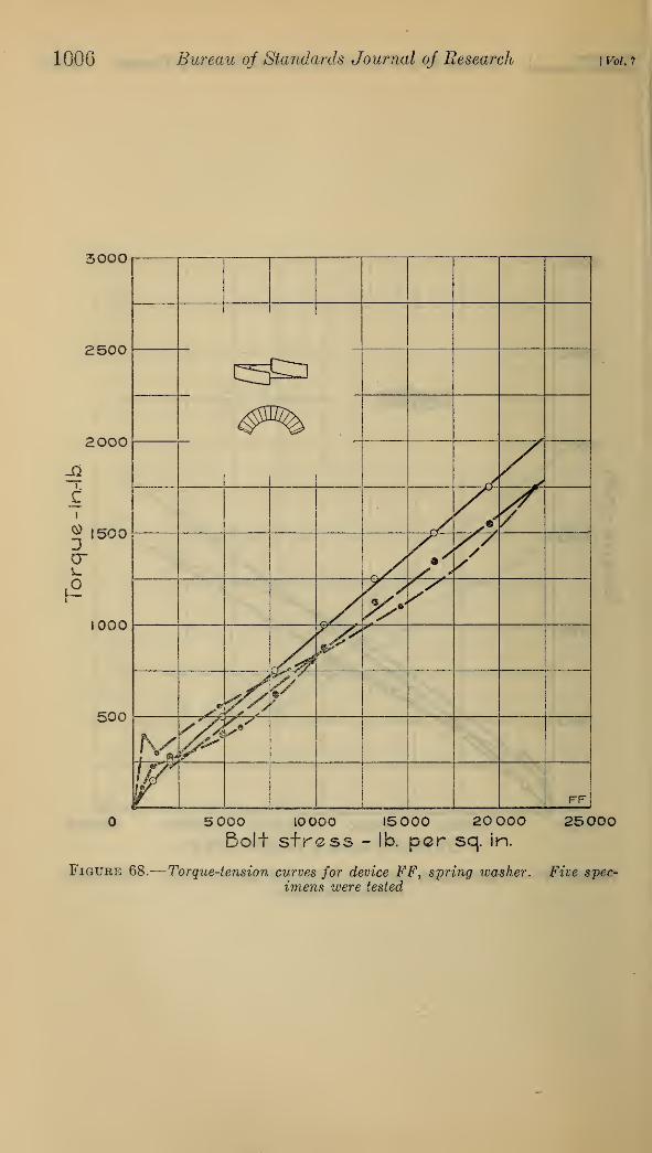
1006 Bureau of Standards Journal of Research \VoU7
3000
2500
2000
i,
c
® 1500
cr
1000
500
y'
.9/sy
z>A?,/'&
&
r$>& 1
rv:y
(r FF
5 000 10000 15 000 20 000 25000Bolt stress - lb. per sq. in.
Figure 68.— Torque-tension curves for device FF, spring washer. Five spec-
imens were tested
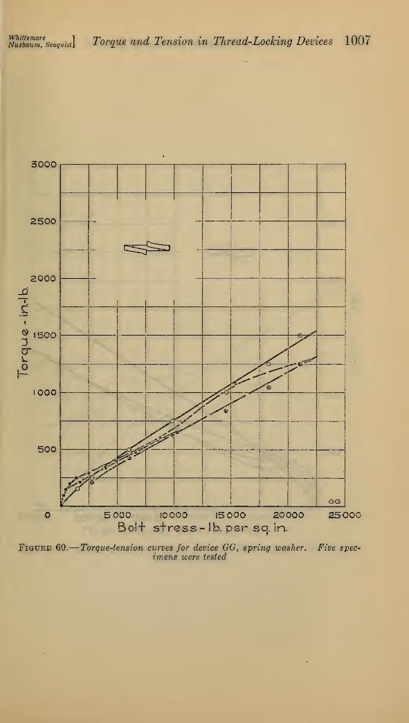
msbaum,e
seaquist] Torque and Tension in Thread-Locking Devices 1007
3000
2500
2000
i
i
® 1500
w
1000
500
<^mr-«^_
! I
1
1
!
i
*•**
ST*
y
^**
o<^
£s^
*<>\fA*%&^1
1
¥ ,!
!
GG
5 000 10000 15 000 20000
Bo!+ stress- lb. per so. in.
25000
Figure 69.
—
Torque-tension curves for device GGfspring washer. Five spec-
imens were tested
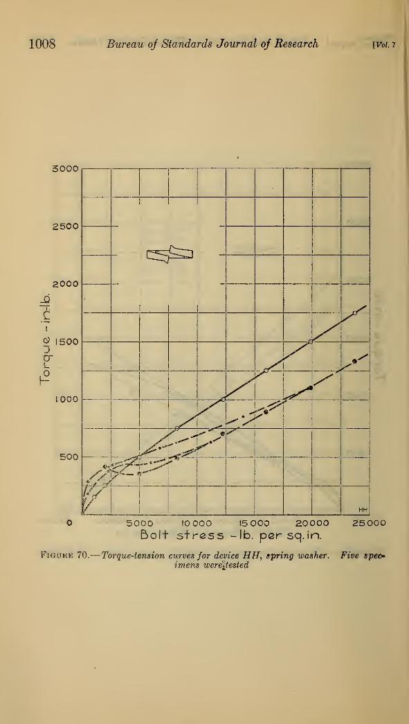
1008 Bureau oj Standards Journal of Research [Vol. 7
3000
2500
2000
I.
C
e> 15003
L
1000
500
c^a
5000 10 000 15 000 20000 25000Bolt stress -lb. pcrsq.in.
Figoke 70.
—
Torque-tension curves for device HH, spring washer. Five spec*imens were\tested
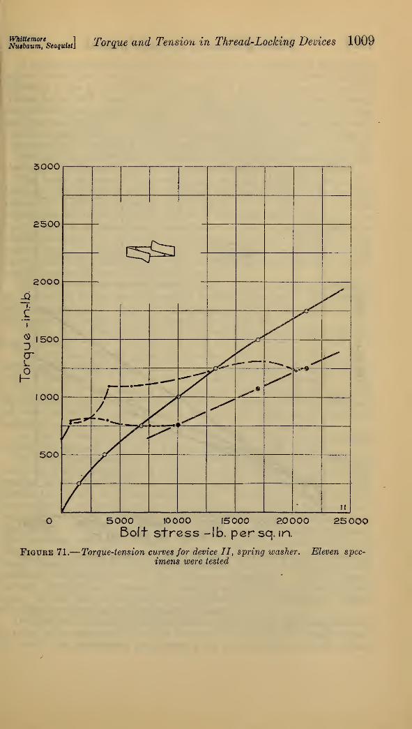
fihubwZ'seaquist] Torque and Tension in Thread-Locking Devices 1009
3000
5000 10000 15000 20000Bolt stress -lb. persq. in.
25000
Figure 71.
—
Torque-tension curves for device II, spring washer. Eleven spec-
imens were tested
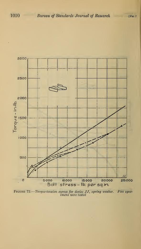
1010 Bureau oj Standards Journal of Research [Vol. 7
3000
2500
2O00
i.
Zi
|2
500
1000
500
5000 10000 15 000 20000 25000Bolt stress - lb. per sq. in.
Figure 72.
—
Torque-tension curves for device JJ, spring washer. Five spec-
imens were tested
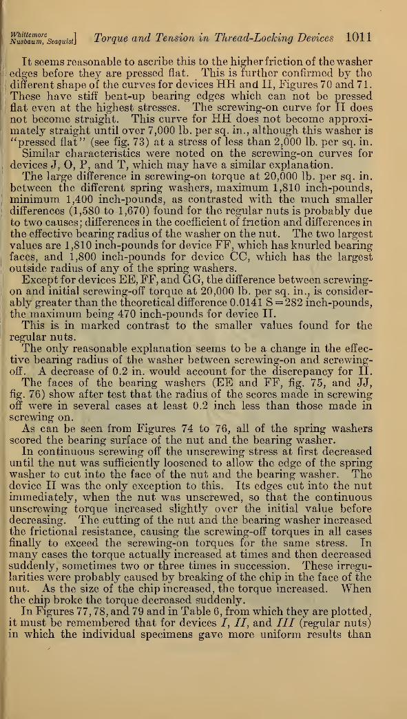
Nusbaum,e
seaquist\ Torque and Tension in Thread-Locking Devices 1011
It seems reasonable to ascribe this to the higher friction of the washeredges before they are pressed flat. This is further confirmed by the
different shape of the curves for devices HH and II, Figures 70 and 71.
These have stiff bent-up bearing edges which can not be pressed
flat even at the highest stresses. The screwing-on curve for II doesnot become straight. This curve for HH does not become approxi-mately straight until over 7,000 lb. per sq. in., although this washer is
"pressed flat" (see fig. 73) at a stress of less than 2,000 lb. per sq. in.
Similar characteristics were noted on the screwing-on curves for
devices J, O, P, and T, which may have a similar explanation.
The large difference in screwing-on torque at 20,000 lb. per sq. in.
between the different spring washers, maximum 1,810 inch-pounds,minimum 1,400 inch-pounds, as contrasted with the much smallerdifferences (1,580 to 1,670) found for the regular nuts is probably dueto two causes; differences in the coefficient of friction and differences in
the effective bearing radius of the washer on the nut. The two largest
values are 1,810 inch-pounds for device FF, which has knurled bearingfaces, and 1,800 inch-pounds for device CC, which has the largest
outside radius of any of the spring washers.Except for devices EE, FF, and GG, the difference between screwing-
on and initial screwing-off torque at 20,000 lb. per sq. in., is consider-
ably greater than the theoretical difference 0.0141 S = 282 inch-pounds,the maximum being 470 inch-pounds for device II.
This is in marked contrast to the smaller values found for theregular nuts.
The only reasonable explanation seems to be a change in the effec-
tive bearing radius of the washer between screwing-on and screwing-off. A decrease of 0.2 in. would account for the discrepancy for II.
The faces of the bearing washers (EE and FF, fig. 75, and JJ,
fig. 76) show after test that the radius of the scores made in screwingoff were in several cases at least 0.2 inch less than those made in
screwing on.
As can be seen from Figures 74 to 76, all of the spring washersscored the bearing surface of the nut and the bearing washer.
In continuous screwing off the unscrewing stress at first decreaseduntil the nut was sufficiently loosened to allow the edge of the springwasher to cut into the face of the nut and the bearing washer. Thedevice II was the only exception to this. Its edges cut into the nutimmediately, when the nut was unscrewed, so that the continuousunscrewing torque increased slightly over the initial value beforedecreasing. The cutting of the nut and the bearing washer increasedthe frictional resistance, causing the screwing-off torques in all cases
finally to exceed the screwing-on torques for the same stress. Inmany cases the torque actually increased at times and then decreasedsuddenly, sometimes two or three times in succession. These irregu-
larities were probably caused by breaking of the chip in the face of thenut. As the size of the chip increased, the torque increased. Whenthe chip broke the torque decreased suddenly.
In Figures 77, 78, and 79 and in Table 6, from which they are plotted,it must be remembered that for devices /, II, and III (regular nuts)in which the individual specimens gave more uniform results than
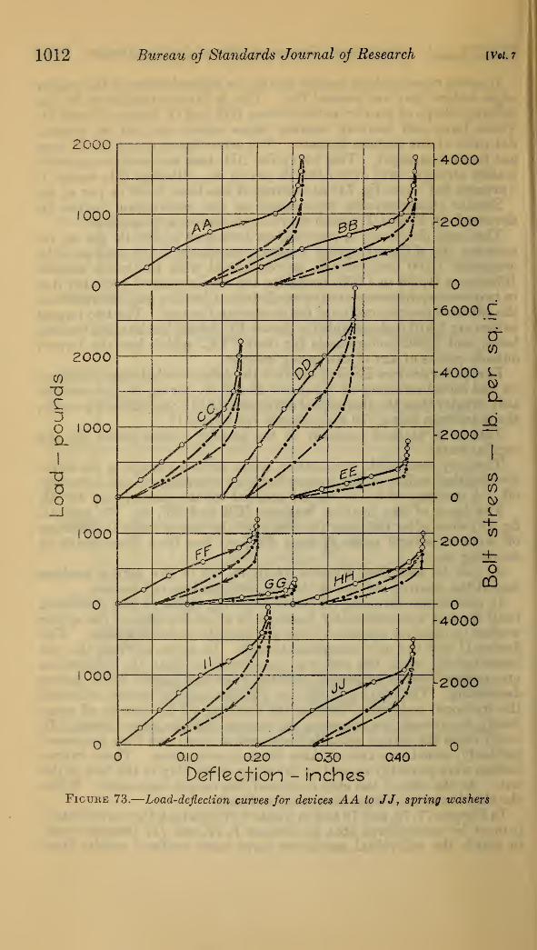
1012 Bureau of Standards Journal of Research [Vol. 7
0001-4000
0,10 0.20 030 Q40
Deflection - inches
Figure 73.
—
Load-defleciion curves for devices AA to JJ, spring washers
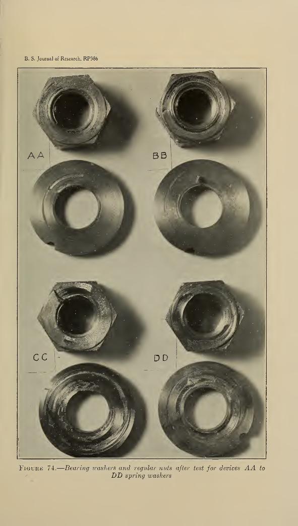
B. S. Journal of Research, RP386
Figure 74.
—
Bearing washers and regular nuts after test for devices AA to
y DD spring washers
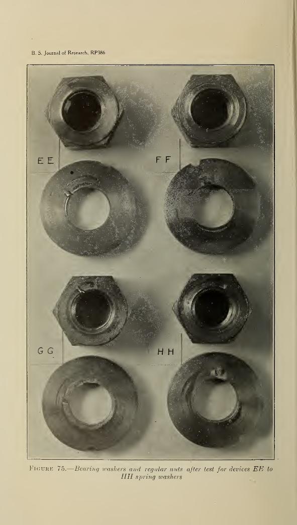
B. S. Journal of Research, RP386
Figure 75.
—
Bearing washers and regular nids after test for devices EE to
HH spring washers
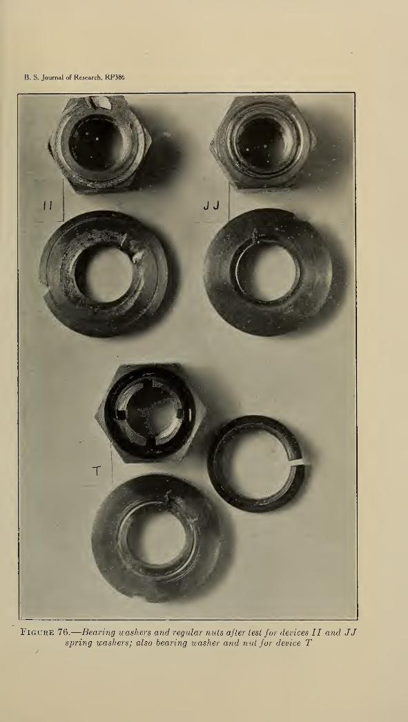
B. S. Journal of Research, RP386
Figure 76.
—
Bearing washers and regular nuts after test for devices II and JJspring washers; also bearing washer and nut for device T
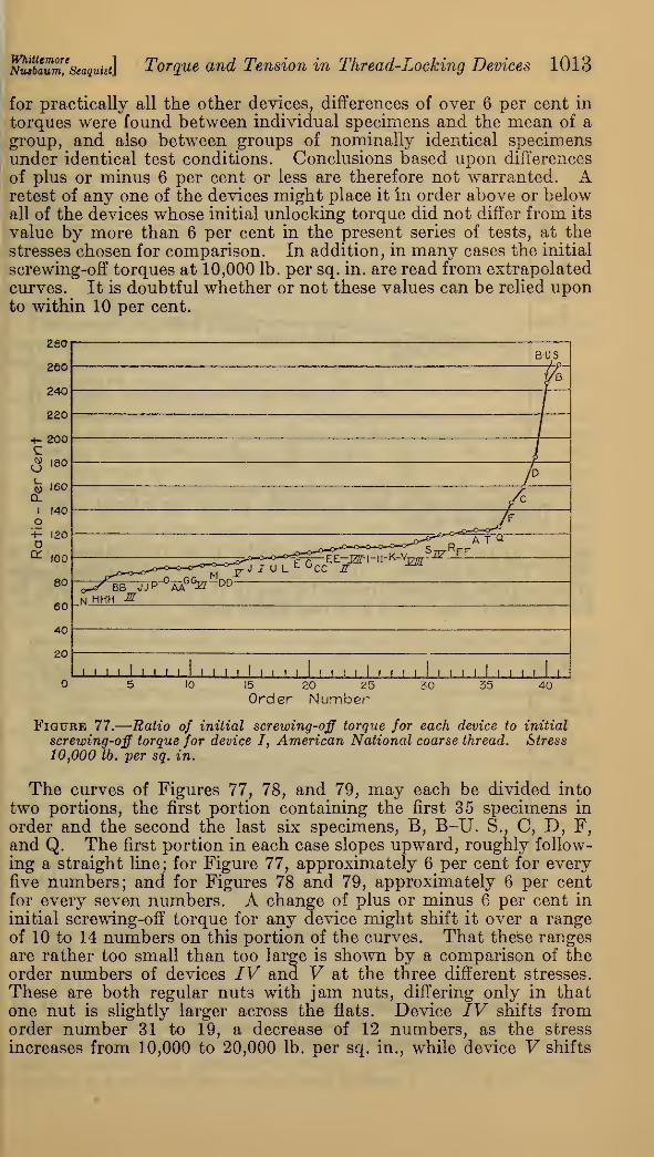
WhiUemoreNutbaum, Seaquist} Torque and Tension in Thread-Locking Devices 1013
for practically all the other devices, differences of over 6 per cent in
torques were found between individual specimens and the mean of a
group, and also between groups of nominally identical specimensunder identical test conditions. Conclusions based upon differences
of plus or minus 6 per cent or less are therefore not warranted. Aretest of any one of the devices might place it in order above or belowall of the devices whose initial unlocking torque did not differ from its
value by more than 6 per cent in the present series of tests, at thestresses chosen for comparison. In addition, in many cases the initial
screwing-off torques at 10,000 lb. per sq. in. are read from extrapolatedcurves. It is doubtful whether or not these values can be relied uponto within 10 per cent.
260 r
260
240
220
200
<¥ 180
160
CJ
l f40O+- 120D^ 100
80
60
40
20
B-US
K HHH MW^7P-°AA6GEr-^-
S7rHFF
I' I' 1 I l I l I I I I i I n i I 1 l ! I l I l I ! I 1 l i
5 10 15 20 25 30 35 40Order Number
Figure 77.
—
Ratio of initial screwing-off torque for each device to initial
screwing-off torque for device I, American National coarse thread. Stress
10,000 lb. per sq. in.
The curves of Figures 77, 78, and 79, may each be divided into
two portions, the first portion containing the first 35 specimens in
order and the second the last six specimens, B, B-U. S., C, D, F,and Q. The first portion in each case slopes upward, roughly follow-
ing a straight line; for Figure 77, approximately 6 per cent for everyfive numbers; and for Figures 78 and 79, approximately 6 per centfor every seven numbers. A change of plus or minus 6 per cent in
initial screwing-off torque for any device might shift it over a rangeof 10 to 14 numbers on this portion of the curves. That these rangesare rather too small than too large is shown by a comparison of theorder numbers of devices IV and V at the three different stresses.
These are both regular nuts with jam nuts, differing only in thatone nut is slightly larger across the flats. Device IV shifts fromorder number 31 to 19, a decrease of 12 numbers, as the stress
increases from 10,000 to 20,000 lb. per sq. in., while device V shifts
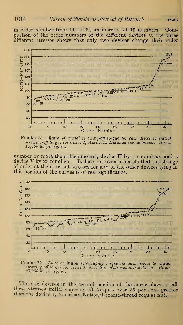
1014 Bureau of Standards Journal of Research [Vol. 7
in order number from 14 to 29, an increase of 15 numbers. Com-parison of the order numbers of the different devices at the threedifferent stresses shows that only two devices change their order
15 20 25Order Number
Figure 78.
—
Ratio of initial screwing-off torque for each device to initial
screwing-off torque for device I, American National coarse thread. Stress15,000 lb. per sq. in.
number by more than this amount; device II by 16 numbers and adevice V by 20 numbers. It does not seem probable that the changeof order at the different stresses for any of the other devices lying inthis portion of the curves is of real significance.
200
o rao
t- 160
£i 140O£ 120oa 100
80
60
40
20
I-UK-'
P M AA„
_BB-HH——-G-NJg-M-EE ELS ^ Tec-
DD JZZ2T &
I 1 I » I l I I « I i i I i I I I ' ' I » ' ' ' ' ' ' I II I 1 I I I
10 15 20 25Order Number
30 35 40
Figure 79.
—
Ratio of initial screwing-off torque for each device to initialscrewing-off torque for device I, American National coarse thread. Stress20,000 lb. per sq. in.
The five devices in the second portion of the curve show at all
these stresses initial screwing-off torques over 25 per cent greaterthan the device 7, American National coarse-thread regular nut.

Nusbaumfseaquist] Torque and Tension in Thread-Locking Devices 1015
X. CONCLUSIONS
Tests were made on 41 devices, including regular nuts (AmericanNational coarse thread, American National fine thread, and U. S.
standard) and commercial devices for preventing rotation of the nuton the bolt in service to determine the relation between static tensile
stress in the bolt (diameter % in.) and the torque required to screwthe nut on and to screw it off the bolt. The results lead to thefollowing conclusions:
1. American National and U. S. standard nuts. The tests were in
general agreement with Persy's theory. The torque required to
screw on the nut was proportional to the stress in the bolt.
The torque required to screw on nominally identical nuts differed
by more than plus or minus 6 per cent from the mean. Larger differ-
ences should be expected in engineering practice.
The torque required to screw the nut off was more irregular butstill roughly proportional to the stress.
The differences between the screwing-on torque and the initial
screwing-off torque were considerably less than the theoretical values,
indicating that the condition of the surfaces changed during the test.
2. There was no great difference between the torques for regular
nuts with jam nuts and the torques for regular nuts without jam nuts.
3. The torques for slotted and castellated regular nuts with cotter
pins were greater than those for regular nuts after the nut had beenscrewed off sufficiently to develop the shearing resistance of the cotter
pin. Unless the pin was a snug fit in the slot, however, the screwing-off torque never exceeded the initial value, because the shearing resist-
ance of the cotter pin was low and the stress in the bolt decreased as
the nut was unscrewed.4. For only a few (B, B-U, S., C, D, F, and Q) of the devices for
preventing rotation of the nut in service were the initial screwing-off
torques for stresses above 10,000 lb. per sq. in. much greater (25 percent) than those for American National coarse-thread regular nuts.
5. For only one of these devices, F, were the initial screwing-off
torques higher than the screwing-on torques.
6. For all the other devices the ratio of the initial screwing-off
torques to the initial screwing-off torques for American Nationalcoarse-thread regular nuts was distributed approximately uniformlybetween 72 per cent and 123 per cent at 10,000, between 75 per centand 115 per cent at 15,000, and between 75 per cent and 112 per centat 20,000 lb. per sq. in. stress in the bolt. The differences betweenindividual specimens of any device were so large that it was possible to
make only a rough arrangement of these devices in order, accordingto their initial unlocking torques.
Except for device V (and possibly II) there was no significant
difference in their order of arrangement at the different stresses
(10,000, 15,000, and 20,000 lb. per sq. in.).
7. When screwing off was continued, several of the devices, VIIand VIII, slotted and castellated nuts with cotter pins, B, B-U. S.,
C, D, F, Q, T, and CC, EE, and II, spring washers, maintained, over a
range of stress, torques relatively much higher than regular nuts.
8. When screwing off was continued to zero stress, over half of the
devices required an appreciable torque to rotate the nut when the
stress in the bolt was zero, and several devices, C, D, F, I, K, P, Q, S,
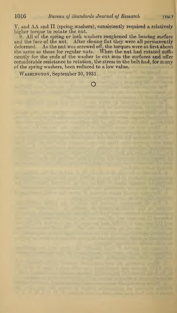
1016 Bureau of Standards Journal oj Research [Vol. 7
V, and AA and II (spring washers), consistently required a relatively
higher torque to rotate the nut.
9. All of the spring or lock washers roughened the bearing surface
and the face of the nut. After closing flat they were all permanentlydeformed. As the nut was screwed off, the torques were at first aboutthe same as those for regular nuts. When the nut had rotated suffi-
ciently for the ends of the washer to cut into the surfaces and offer
considerable resistance to rotation, the stress in the bolt had, for manyof the spring washers, been reduced to a low value.
Washington, September 30, 1931.
o
Related Documents