October 2011 i s s u e 84 written by rail engineers for rail engineers available online at www.therailengineer.com The Innovation Challenge An exclusive interview with Steve Yianni, Network Rail’s Chief Engineer. Access for All The key objective of the AfA programme is the provision of step-free access. 7 years and still holding fast HoldFast have supported the rail engineer in every issue for seven consecutive years. World launch for Blackpool Tram BLACKPOOL IS THE FIRST TRAM OPERATOR TO ORDER BOMBARDIER’S NEW FLEXITY 2 TRAM

The Rail Engineer - Issue 84 - October 2011
Mar 16, 2016
The Rail Engineer Issue 84 October 2011
Welcome message from author
This document is posted to help you gain knowledge. Please leave a comment to let me know what you think about it! Share it to your friends and learn new things together.
Transcript

October 2011
i s s u e
84
written by rail engineers for rail engineers available online at www.therailengineer.com
The InnovationChallengeAn exclusive interview withSteve Yianni, Network Rail’s Chief Engineer.
Accessfor AllThe key objective of the AfAprogramme is the provision ofstep-free access.
7 years and stillholding fastHoldFast have supported therail engineer in every issue forseven consecutive years.
World launch forBlackpool Tram
BLACKPOOL IS THE FIRST TRAM OPERATOR TO ORDER BOMBARDIER’S NEW FLEXITY 2 TRAM

HoldFast Level Crossings Ltd, Brockenhurst, Chedworth, Cheltenham, GL54 4AA
Please contact Mark Coates Smith Mobile: +447970 656143 Fax: +441285 720748
Email: [email protected]
www.holdfastsolutions.com
MAD E F RO
M1
00
%R
ECYCLEDM
AT
ER
IALS
The HoldFast system is manufactured by Rosehill Polymers Ltd
WHY WOULDN’T YOU?
HoldFast panels are made from 100% recycled rubber, meaning they protect the environment as well as providing solutions for rail, road, tram and pedestrian routes.
Why wouldn’t you choose HoldFast?

october 2011 | the rail engineer | 3welcome
Well, it’s Happy Seventh Birthday.....to us. Ourcover has a picture of a bonny tram, but also a largenumber 84. So, thanks to everyone who hassupported us - our readers and our advertisers, oneof whom has been with us every issue from dayone. Thanks HoldFast!
It was back in March 2008 that the rail engineerstood on a gale-swept Blackpool beach gazing outto the recently stranded vessel MV Riverdance. Thisill-fated ship was cut up on site despite severalattempts to raise her. All the while, work continuedon the refurbishment of the tram system and it isthe culmination of all this hard work that is our leadarticle this month. The trams have arrived and TerryWhitley was there for the World Roll-out of theBombardier FLEXITY 2 fleet.
Some of you may have been unlucky enough tohave been caught up in the chaos caused by theCroydon mudslide at the beginning of August thatclosed the main London – Brighton line. The impacton the entire transport infrastructure in the SouthEast was immense. I’ve been talking to two peoplewho were directly involved in sorting out the trainsand the engineering to try and discover thepressures of such a major incident.
Our Victorian forebears were never renowned forproviding sympathetic access to stations. For alltheir emerging philanthropy they seemed to putcommercial considerations long before any help forthe disabled. So it’s always a challenge to retrofitsuch facilities. Stuart Rackley reviews the currentposition of legislation and looks at some flagshipprojects that show what can really be done.
David Shirres has a couple of articles in thismonth’s magazine. In a way they are linked as theyboth deal with innovation. In his piece about trackwarning systems he summarises some of thehistory and the way that, despite developments inEurope, the UK systems seemed to havedisappeared into the long grass.
The present position is far more encouraging withnew systems - and new acronyms emerging.
Once upon a time there was a railways staffsuggestion scheme. Very vigorous it was too,although sometimes a little perplexed by moreadvanced suggestions. With many of the ‘staff’being employed by contractors it’s now theirturn to come up with the suggestions. TheNetwork Rail ‘bright ideas’ website sends out thechallenge.
In his debut article on the MacroRail exhibitionat Long Marston, Paul Curtis obviously didn’t gethimself lost in that huge complex. There wasplenty to see and plenty of room to see it.Perhaps next year it’ll be MegaRail. Where will itend?
The Chiltern Railways’ Evergreen brand justseems to keep going. It started with Evergreen 1(logically). Then came Evergreens 2 and 3, thefinal completion of which came at the end ofAugust. But, as Clive Kessell reminds us, there’stalk of a sequel – Evergreen 4 (again logically) –and the construction of the Bicester chord. Whatseems to have been lost in the mists of timethough is the origin of the project name. Perhapsit too may be logical.
As a past master of dialect writing, Stuart Marshtreats us to a snippet of true Lancashire at the endof his piece on the Rochdale resignalling. Here is ascheme that results in a replacement signalboxbeing placed within shouting distance of another.This unusual arrangement comes about becausethe original was smack in the way of a newManchester Metrolink route. The hunt was on for anew site which just happens to be rather close toCastleton East.
And what do I detect in the political press? Talk ofextra infrastructure spending... including railways.The Treasury denies such a move, so it’s probably adead cert. Hold tight everyone.
Operating noticeGrahame Taylor’s
EditorGrahame [email protected]
Production and designAdam O'[email protected]
Engineering [email protected]@[email protected]@therailengineer.comgraeme.bickerdike@[email protected]@[email protected]@therailengineer.comstuart.rackley@[email protected]
AdvertisingAsif [email protected] [email protected] [email protected]
the rail engineerAshby House, Bath Street, Ashby-de-la-Zouch Leicestershire, LE65 2FH
Telephone: 01530 56 00 31Fax: 01530 41 21 66Email: [email protected]: www.therailengineer.com
Editorial copyEmail: [email protected]
Free controlled circulation Email: [email protected]
The small printthe rail engineer is published by RailStaffPublications Limited and printed by Pensord.
© All rights reserved. No part of this magazine may bereproduced in any form without the prior writtenpermission of the copyright owners.
Sister publication of
World launch for Blackpool Tram 6Bombardier’s new Flexity 2 tram is unveiled inBlackpool.
Mud, mud, glorious mud 8What happened after 2,500 tonnes ended up on theline at South Croydon.
Access for All 12A look at Network Rail’s AfA programme to makestations accessible.
Chiltern Renaissance 15
The final installment of work to restore the route toits past glories.
The Innovation Challenge 20An exclusive interview with Steve Yianni, NetworkRail’s Chief Engineer.
MNR goes WILD 38
How to monitor wheel flats before they get out ofhand.
A new tool in the box 42The continuing development of rail milling.
The future’s bright, the future’s ATWS 55David Shirres looks at the LOWS initiative and thenext generation of ATWS.
Plant & Equipment, Concrete November
Electrification/Power, Light Rail December
in this issue
forthcomingfeatures

Over the years, the rail engineerhas covered various reasons fordelays to railway infrastructureprojects. Great Crested Newts aresome of the most regular culprits.
But now the ancient Romanstake the blame as the ruins of a2,000 year old Roman bath househave been discovered on landbeing re-developed as part of the£5.5bn Thameslink programme.
The ruins, which are believed tobe one of the biggest Roman findsin London on the south side of theRiver Thames, have been uncoveredon the corner of London BridgeStreet and Borough High Street. Thesite has been earmarked for theconstruction of a new office block.
Network Rail has commissioned ateam of specialist archaeologists fromOxford Archaeology and Pre-Construct Archaeology to excavatethe site. Although work is at an earlystage, the bath house appears toinclude a range of rooms including acold plunge bath as well as hot rooms
warmed by under floor heating.Elsewhere on the site, substantialwalls are thought to belong topredecessors of St Thomas’ hospital,which used to stand on the site.
Network Rail, in agreement withthe London Borough of Southwark,is exploring ways of preserving theremains beneath the new buildingto be constructed on the site.
4 | the rail engineer | october 2011 news
Steel for a major new railwayproject in France will come from theUK. Tata Steel (formerly Corus) hassecured the contract to supply84,000 tonnes of rail for 188 miles(302km) of a new TGV line in France.
The steel will be manufactured inScunthorpe before being rolledinto rail at Tata Steel´s mill inHayange, north-east France, fordelivery from 2014. The companywill also supply switches and
crossings to the constructionconsortium COSEA. The total valueof the steel supplied will be around€80 million.
The South-Europe-Atlantiqueproject is the largest public-privatepartnership contract ever signed inFrance´s rail sector. It will connectsouth-western France with high-speed rail services from northernEurope, including London, Paris,Brussels and Amsterdam.
Trains travelling at 300km perhour (186mph) will reduce thejourney time from Paris toBordeaux to two hours and fiveminutes. Work on building 400 civilengineering structures, including19 viaducts and seven cut-and-cover tunnels, will start in the firsthalf of 2012. At the peak of theproject 4,500 construction workerswill be employed. The line is due toopen in 2016.
British steel for new TGV line
Roman remains to blameENVIRONMENT
IN BRIEF
Congested stationsNetwork Rail has published an analysis
of passenger congestion at stations anda toolkit of potential measures toaddress the problem.
The report - the Network RouteUtilisation Strategy: Stations -recommends that action is taken toidentify ways to relieve passengercongestion at the following 11 stationsby 2019: Basingstoke, Bristol Parkway,Clapham Junction, Liverpool LimeStreet, London Charing Cross, LondonFenchurch Street, London Victoria,Preston, Surbiton, Watford Junction andWimbledon.
Paul Plummer, Network Rail groupstrategy director, said: “As more peoplechoose to travel by rail, it’s vital thatpassenger congestion is tackled or somestations risk becoming victims of theirown success.”
Sunlight at Kings CrossThe first section of roof at Kings Cross
Station to be refurbished has now beenrevealed. As reported in the railengineer issue 82 (August 2011) the roofis being stripped back to bare metal,repaired, repainted and reglazed.
Recently, workers slid 130 tonnes ofscaffolding 80m along the length of theroof to shield passengers during thenext phase of work. The newly-exposedsection allowed sunlight to penetratethe station for the first time for years.
7,500 clear glass panels and over 1,400photovoltaic panels, which will supply10% of the station’s electrical power, arereplacing the yellowing fibreglass whichwas installed in the 1970s.
Crossrail signallingNo surprises as Crossrail announced
the shortlist for the supply of the centralsection signalling system recently. Thecompanies that will be invited to tenderfor this £70 million contract later thisyear are Bombardier, Invensys Rail,Siemens, Signalling Solutions and Thales.
The new railway signalling and controlsystem, which will support AutomaticTrain Operation, will enable operation of24 trains per hour during the peakbetween Paddington and Whitechapeland will be designed to supportenhancement to 30 trains per hourthrough the central section at a laterdate.
TRACK
october 2011 | the rail engineer | 5news
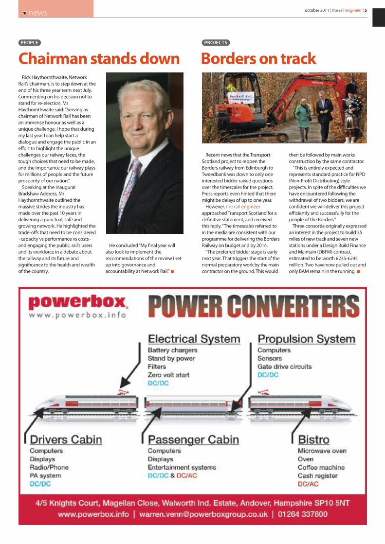
Rick Haythornthwaite, NetworkRail’s chairman, is to step down at theend of his three year term next July.Commenting on his decision not tostand for re-election, MrHaythornthwaite said: “Serving aschairman of Network Rail has beenan immense honour as well as aunique challenge. I hope that duringmy last year I can help start adialogue and engage the public in aneffort to highlight the uniquechallenges our railway faces, thetough choices that need to be made,and the importance our railway playsfor millions of people and the futureprosperity of our nation.”
Speaking at the inauguralBradshaw Address, MrHaythornthwaite outlined themassive strides the industry hasmade over the past 10 years indelivering a punctual, safe andgrowing network. He highlighted thetrade-offs that need to be considered- capacity vs performance vs costs -and engaging the public, rail’s usersand its workforce in a debate aboutthe railway and its future andsignificance to the health and wealthof the country.
He concluded “My final year willalso look to implement therecommendations of the review I setup into governance andaccountability at Network Rail.”
PEOPLE
Chairman stands down
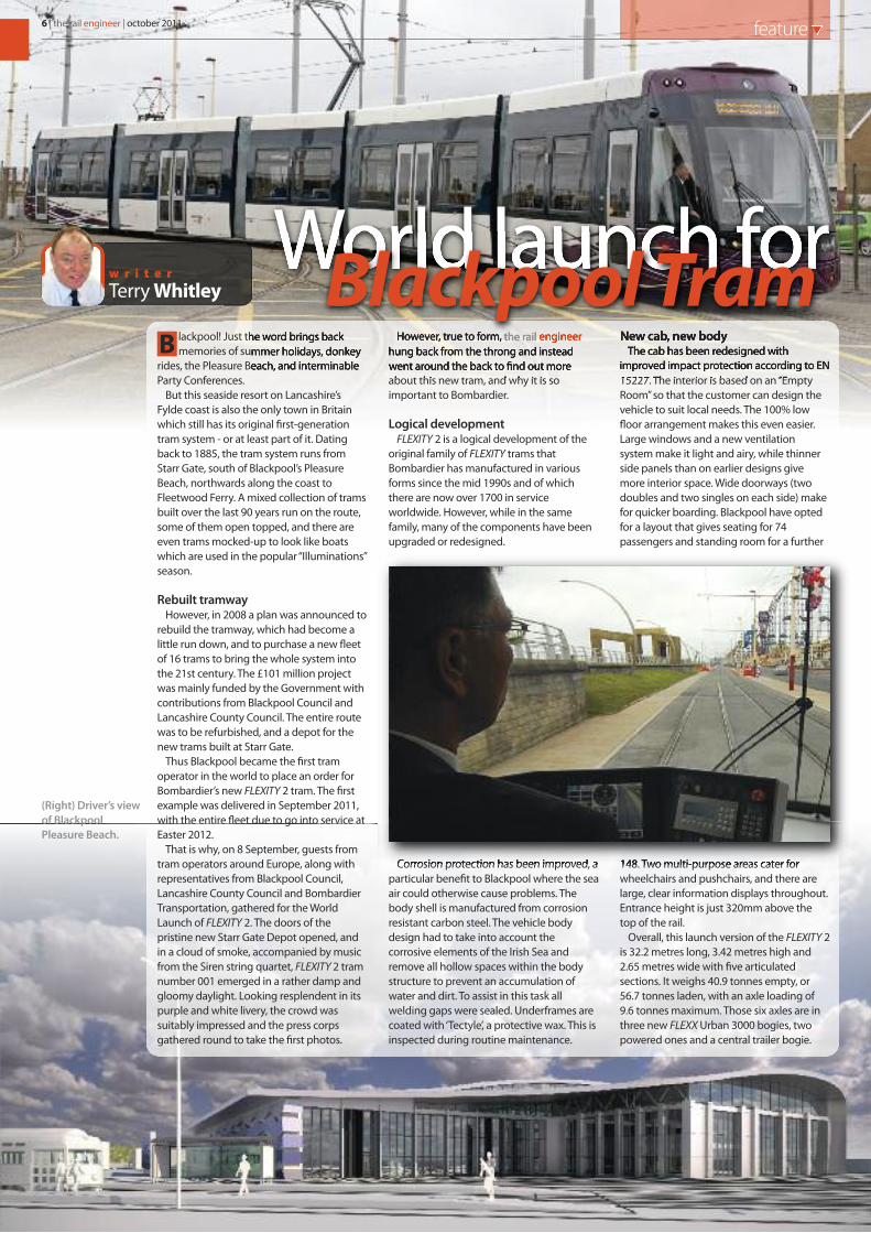
Recent news that the TransportScotland project to reopen theBorders railway from Edinburgh toTweedbank was down to only oneinterested bidder raised questionsover the timescales for the project.Press reports even hinted that theremight be delays of up to one year.
However, the rail engineerapproached Transport Scotland for adefinitive statement, and receivedthis reply. “The timescales referred toin the media are consistent with ourprogramme for delivering the BordersRailway on budget and by 2014.
“The preferred bidder stage is earlynext year. That triggers the start of thenormal preparatory work by the maincontractor on the ground. This would
then be followed by main worksconstruction by the same contractor.
“This is entirely expected andrepresents standard practice for NPD(Non-Profit Distributing) styleprojects. In spite of the difficulties wehave encountered following thewithdrawal of two bidders, we areconfident we will deliver this projectefficiently and successfully for thepeople of the Borders.”
Three consortia originally expressedan interest in the project to build 35miles of new track and seven newstations under a Design Build Financeand Maintain (DBFM) contract,estimated to be worth £235-£295million. Two have now pulled out andonly BAM remain in the running.
PROJECTS
Borders on track
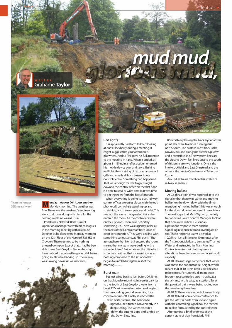
6 | the rail engineer | october 2011 feature
lackpool! Just the word brings backmemories of summer holidays, donkey
rides, the Pleasure Beach, and interminableParty Conferences.
But this seaside resort on Lancashire’sFylde coast is also the only town in Britainwhich still has its original first-generationtram system - or at least part of it. Datingback to 1885, the tram system runs fromStarr Gate, south of Blackpool’s PleasureBeach, northwards along the coast toFleetwood Ferry. A mixed collection of tramsbuilt over the last 90 years run on the route,some of them open topped, and there areeven trams mocked-up to look like boatswhich are used in the popular “Illuminations”season.
Rebuilt tramwayHowever, in 2008 a plan was announced to
rebuild the tramway, which had become alittle run down, and to purchase a new fleetof 16 trams to bring the whole system intothe 21st century. The £101 million projectwas mainly funded by the Government withcontributions from Blackpool Council andLancashire County Council. The entire routewas to be refurbished, and a depot for thenew trams built at Starr Gate.
Thus Blackpool became the first tramoperator in the world to place an order forBombardier’s new FLEXITY 2 tram. The firstexample was delivered in September 2011,with the entire fleet due to go into service atEaster 2012.
That is why, on 8 September, guests fromtram operators around Europe, along withrepresentatives from Blackpool Council,Lancashire County Council and BombardierTransportation, gathered for the WorldLaunch of FLEXITY 2. The doors of thepristine new Starr Gate Depot opened, andin a cloud of smoke, accompanied by musicfrom the Siren string quartet, FLEXITY 2 tramnumber 001 emerged in a rather damp andgloomy daylight. Looking resplendent in itspurple and white livery, the crowd wassuitably impressed and the press corpsgathered round to take the first photos.
However, true to form, the rail engineerhung back from the throng and insteadwent around the back to find out moreabout this new tram, and why it is soimportant to Bombardier.
Logical developmentFLEXITY 2 is a logical development of the
original family of FLEXITY trams thatBombardier has manufactured in variousforms since the mid 1990s and of whichthere are now over 1700 in serviceworldwide. However, while in the samefamily, many of the components have beenupgraded or redesigned.
Corrosion protection has been improved, aparticular benefit to Blackpool where the seaair could otherwise cause problems. Thebody shell is manufactured from corrosionresistant carbon steel. The vehicle bodydesign had to take into account thecorrosive elements of the Irish Sea andremove all hollow spaces within the bodystructure to prevent an accumulation ofwater and dirt. To assist in this task allwelding gaps were sealed. Underframes arecoated with ‘Tectyle’, a protective wax. This isinspected during routine maintenance.
New cab, new bodyThe cab has been redesigned with
improved impact protection according to EN15227. The interior is based on an “EmptyRoom” so that the customer can design thevehicle to suit local needs. The 100% lowfloor arrangement makes this even easier.Large windows and a new ventilationsystem make it light and airy, while thinnerside panels than on earlier designs givemore interior space. Wide doorways (twodoubles and two singles on each side) makefor quicker boarding. Blackpool have optedfor a layout that gives seating for 74passengers and standing room for a further
148. Two multi-purpose areas cater forwheelchairs and pushchairs, and there arelarge, clear information displays throughout.Entrance height is just 320mm above thetop of the rail.
Overall, this launch version of the FLEXITY 2is 32.2 metres long, 3.42 metres high and2.65 metres wide with five articulatedsections. It weighs 40.9 tonnes empty, or56.7 tonnes laden, with an axle loading of9.6 tonnes maximum. Those six axles are inthree new FLEXX Urban 3000 bogies, twopowered ones and a central trailer bogie.
B
w r i t e rTerry Whitley
World launch forBlackpool Tram
(Right) Driver’s viewof BlackpoolPleasure Beach.

october 2011 | the rail engineer | 7feature
BogiesLike the whole tram, the FLEXX Urban 3000
is a natural development of earlier, well-established bogies. It has a short wheelbaseat only 1,850mm which allows the tram tonegotiate curves as tight as 25m in service(20m in the depot). To keep the whole bogiecompact, and allow it to be fitted to 100%low floor trams, the water-cooled tractionmotors are mounted longitudinally on theoutside of the bogie frames, one each side.These connect with bevel-gearboxesmounted on the outboard end of the axles.The 125kW motors are cooled from radiatorsmounted on the roof of the tram. There is afully-integrated hydraulic brake system, aswell as an electromagnetic track brake.
The FLEXX Urban 3000 is a modular design.Converting it from an inside frame type, as onthe Blackpool tram, to an outside frame allowsit to be used on metre-gauge systems whileotherwise utilising the same components.Wheel diameters can vary between 560mmand 640mm (600mm in Blackpool). Primarysuspension uses elastomeric springs.The secondary suspensionalso uses
elastomeric springs with lateral and verticalhydraulic dampers, although steel springs areavailable for some applications. The wheelshave a rubber resilient strip between wheeland tyre, as on most trams, to give a smootherand quieter ride. Externally, the bogies arehidden behind side fairings.
Power and controlPower for the tram is taken from the 600V
DC overhead system through a Stemmann-Technik pantograph. Interestingly,Blackpool’s heritage fleet ran on a non-standard 550V supply - it was only upgradedto 600V this year for these new trams.
Bombardier’s own MITRAC 2 propulsioncontrol technology is fitted. This includes aregenerative braking system which harvestselectrical energy during braking. The size ofthe traction converters has been reduced, aswell as the auxiliary converters that supplypower for lighting, air-conditioning,information and control systems.
The FLEXITY 2 can even be fitted withBombardier’s novel PRIMOVE induction-loopcatenary-less power acquisition system,although this is not part of the Blackpoolspecification.
Starr GateThe new depot at Starr Gate is primarily set
up to house and maintain the new tram fleet.Some of the heritage trams will be servicedthere, and one was sitting in the depot at thelaunch, but primarily they will be housed atthe old Rigby Road depot. Once the fullFLEXITY 2 fleet is in service, the heritagetrams will continue to operate in regularservice throughout the year, providing apeak time alternate service between the newtrams. Otherwise the 21st century trams willrun the route, resulting in a quieter andsmoother ride, and a journey time that willbe 15 minutes quicker from end to end.
Staying on a seaside theme, after the 16new Blackpool trams have been delivered,the factories in Vienna, Austria, where thecabs are manufactured, and the assemblyplant in Bautzen, Germany, will change overto making 7-segment trams for the nextcustomer - Australia’s Gold Coast RapidTransit. 14 of the 45 metre long trams will be
delivered “down under” by 2014.
FLEXX Urban3000 Bogie.
8 | the rail engineer | october 2011 feature
onday 1 August 2011. Just anotherMonday morning. The weather was
fine. There was the weekend’s engineeringwork to discuss along with plans for thecoming week. All was as usual.
Phil Barnes, Network Rail’s CurrentOperations manager sat with his colleaguesin the morning meeting with his RouteDirector, as he does every Monday morningon the 12th Floor of the Network Rail HQ inCroydon. There seemed to be nothingunusual going on. Except that.... had he beenable to see East Croydon Station he mighthave noticed that something was odd. Trainsgoing south were backing up. The railwaywas slowing down. All was not well.
Red lightsIt is apparently bad form to keep looking
at one’s Blackberry during a meeting. Itmight suggest that your attention iselsewhere. And so Phil gave his full attentionto the meeting in hand. When it ended, atabout 11.15hrs, in a reflex action he turnedhis mobile device over and saw a flashingred light, then a string of texts, unansweredcalls and emails all from Sussex RouteControl Centre. Something had happened.That was enough for Phil to go straightdown to the control office on the first floor.No time to read or write emails. It was timeto get the news from the horse’s mouth.
When everything is going to plan, railwaycontrol offices are quiet places with the oddphone call, controllers standing up andstretching, and general peace and quiet. Thiswas not the scene that greeted Phil as heentered the room. All the controllers wereon their phones. There was definitelysomething up. There was urgency in the air -the faces of the Control staff bore looks ofdeep concentration. They were dealing withsomething serious and, as Phil put it, “Theatmosphere that I felt as I entered the roommeant that my team were dealing with amajor incident”. But whatever the office hadto contend with at that moment, it was asnothing compared to the situation thatbegan to unfold during the rest of themorning.............
Burst mainBut let’s wind back to just before 09.45hrs
on that Monday morning. In a quiet park justto the South of East Croydon, water from aburst 12” cast iron main started soaking intothe surrounding ground, searching for aconvenient run-off. Finally, it reached the
drain of its dreams - the London toBrighton Line situated conveniently in a
deep cutting. The water cascadeddown the cutting slope and landed onthe Down Slow line.
It’s worth explaining the track layout at thispoint. There are five lines running duenorth/south. The eastern-most track is theDown Slow, and alongside are the Up Slowand a reversible line. The western lines arethe Up and Down fast lines. Just to the southof this point are two junctions. One is theline to Uckfield and East Grinstead and theother is the line to Caterham and TattenhamCorner.
Around 57 trains travel on this stretch ofrailway in an hour.
Moving ballastAt 9.53hrs a train driver reported in to the
signaller that there was water and ‘movingballast’ on the down slow. With the drivermentioning ‘moving ballast’ this was enoughfor the down slow to be closed immediately.The next steps that Mark Wyborn, the dutyNetwork Rail Route Control Manager, took atthat time were critical. He sent anOperations response team and theSignalling response team to investigate onsite. Those response teams arrived at10.05hrs - just a little over 10 minutes afterthe first report. Mark also contacted ThamesWater and instructed his Train RunningControl team to start plotting servicealterations based on a reduction of networkcapacity.
At 10.10 a message came back that waterwas above the conductor rail height, whichmeant that at 10.11hrs both slow lines hadto be closed. Fortunately all trains werebrought to a controlled stop - that is, at asignal - and, in this case, at a station. So, atthis point, all trains were being routed overthe remaining three lines.
At 10.22 there was a report of an earth slip.At 10.30 Mark convened a conference to
get the latest reports from site and agreewith the controlling signal box the revisedtrain plan formulated by the control team.
After getting a brief overview of thecurrent state of play from Mark, Phil
M
mud, mud,
Grahame Taylorw r i t e r
‘I can no longerSEE my railway!’
PHOTO: LUCINDA OFFER
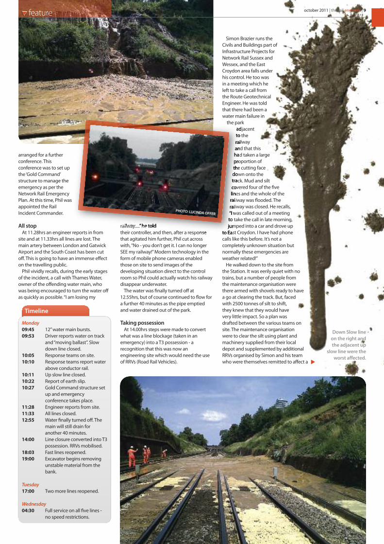
arranged for a furtherconference. Thisconference was to set upthe ‘Gold Command’structure to manage theemergency as per theNetwork Rail EmergencyPlan. At this time, Phil wasappointed the RailIncident Commander.
All stopAt 11.28hrs an engineer reports in from
site and at 11.33hrs all lines are lost. Themain artery between London and GatwickAirport and the South Coast has been cutoff. This is going to have an immense effecton the travelling public.
Phil vividly recalls, during the early stagesof the incident, a call with Thames Water,owner of the offending water main, whowas being encouraged to turn the water offas quickly as possible. “I am losing my
railway.....” he toldtheir controller, and then, after a responsethat agitated him further, Phil cut acrosswith, “No - you don’t get it. I can no longerSEE my railway!” Modern technology in theform of mobile phone cameras enabledthose on site to send images of thedeveloping situation direct to the controlroom so Phil could actually watch his railwaydisappear underwater.
The water was finally turned off at12.55hrs, but of course continued to flow fora further 40 minutes as the pipe emptiedand water drained out of the park.
Taking possessionAt 14.00hrs steps were made to convert
what was a line blockage (taken in anemergency) into a T3 possession - arecognition that this was now anengineering site which would need the useof RRVs (Road Rail Vehicles).
Simon Brazier runs theCivils and Buildings part ofInfrastructure Projects forNetwork Rail Sussex andWessex, and the EastCroydon area falls underhis control. He too wasin a meeting which heleft to take a call fromthe Route GeotechnicalEngineer. He was toldthat there had been awater main failure in
the parkadjacentto therailwayand that thishad taken a largeproportion ofthe cutting facedown onto thetrack. Mud and siltcovered four of the fivelines and the whole of therailway was flooded. Therailway was closed. He recalls,“I was called out of a meetingto take the call in late morning,jumped into a car and drove up
to East Croydon. I have had phonecalls like this before. It’s not acompletely unknown situation butnormally these emergencies areweather related!”
He walked down to the site fromthe Station. It was eerily quiet with notrains, but a number of people fromthe maintenance organisation werethere armed with shovels ready to havea go at clearing the track. But, facedwith 2500 tonnes of silt to shift,they knew that they would havevery little impact. So a plan wasdrafted between the various teams onsite. The maintenance organisationwere to clear the silt using plant andmachinery supplied from their localdepot and supplemented by additionalRRVs organised by Simon and his teamwho were themselves remitted to affect a
Monday09:45 12” water main bursts.09:53 Driver reports water on track
and “moving ballast”. Slow down line closed.
10:05 Response teams on site.10:10 Response teams report water
above conductor rail. 10:11 Up slow line closed.10:22 Report of earth slip.10:27 Gold Command structure set
up and emergency conference takes place.
11:28 Engineer reports from site.11:33 All lines closed.12:55 Water finally turned off. The
main will still drain for another 40 minutes.
14:00 Line closure converted into T3possession. RRVs mobilised.
18:03 Fast lines reopened.19:00 Excavator begins removing
unstable material from the bank.
Tuesday17:00 Two more lines reopened.
Wednesday04:30 Full service on all five lines -
no speed restrictions.
Timeline
feature october 2011 | the rail engineer | 9
Down Slow lineon the right andthe adjacent up
slow line were theworst affected.
PHOTO: LUCINDA OFFER

repair to thecutting face.The water had
been turned off atthis stage and the
water had stoppedrunning but parts of thecutting face were fallingout as they consideredtheir solution.
Calling BAMHistorically, Network
Rail had a frameworkcontract with BAM Nuttall.
The contract had, in fact, just finished andalthough the new contractor was on boardthey were not in a position to mobilisequickly enough. So BAM was used as theywere able to respond very quickly becauseof all their previous experience. One of theirearthworks contract managers was availableand was able to get to site reasonably soon.At their site meetings they decided how toremove the material and how to make safe
and re-profile the cutting slope.
Regular teleconferences with theoperations team were used to discussstrategies and timescales.
Simon recalls the site arrangements. “Railaccess for RRVs was from South Croydonwhich was relatively close. We brought along-reach excavator through the gates ofthe park to the top of the cutting. Some ofthe gates had to be removed so that it couldget in and gently trundled across the park.The excavator needed to be relatively lightotherwise it stood a chance of joining therest of the mud and sliding down the bank.
“The failed material began to be removedat around 7pm. The excavator worked for
about 14hours to completely re-profilethe slip area.”Clearing the spoil on the track was a
joint effort between the maintenancesection and BAM who provided the RRVsfrom subcontractor Keltbray.
Rob Pearson, BAM Nuttall’s contractsmanager, Colin Haytor Network Rail’s seniorconstruction manager, and Simon were thecoordinating presence on site.
Pots of damageIn parallel to the spoil removal there was a
need to repair damage to the signalling andto the third rail. Many conductor rail insulators(pots) had to be changed because the siltcontamination would have been almostimpossible to remove. The land slip knockedover parts of the conductor rail, wrecked thetrack ballast and filled up the drains.
Referring to similar emergencies Simonknows that, “It’s the knowledge rather thanthe kit that’s critical. You can usually get kitfrom some sort of source, it’s getting theexperience to site that makes all thedifference.”
Although by this time many routes intoLondon and around Croydon and Gatwickwere gridlocked, Simon was able to getstaff in and out of the site via the ‘sideentrance’ - that is via the Kent route.
There was, of course, 24hr working until thejob was finished. Afterwards there werefollow-up works like removing trees andinstalling drainage to the cutting face. All in allthere was work on site for about 10 days.
ReopeningBack in the Control Office, the primary
focus was to get something open, and thisthey did by 18.03hrs on the Mondayevening when the fast lines reopened.These had been affected more by waterthan by mud.
Network Rail and its customers First CapitalConnect and Southern worked through thenight to construct a new train plan based onthe restricted track layout of just two linesthrough one of the busiest networks in thecountry.
The media management was excellentwith images of the mudslide being beamedonto the large passenger informationscreens at Gatwick and at the major Londonstations and by printed posters erected atmany stations on the Sussex network. Bythe following morning the public had gotthe message. Trains on the Tuesday werestrangely quiet.
With the signalling tested four linesreopened at 17.00hrs Tuesday which wasenough to run a full service. By 04.30hrsWednesday morning there was a fullnetwork with no speed restrictions.
Phil summarised that “Some realpositives came out from the SouthCroydon landside. There were nopassenger accidents, no trapped trains, noworkforce injuries and, after thousands oftonnes of mud and silt were dumped onthe railway, a full network was availablewithin 40 hours - a real testament to theteamwork and effort shown by all of thoseinvolved”
But, Phil adds wryly, “After such asignificant incident that led to a majorimpact on the journey experience for ourtravelling customers, it is absolutelyimperative to reopen and run a perfectservice the following day. But asWednesday got underway, there werereports of gas canisters on fire near the lineside at Sanderstead. At noon there was atrain failure and, sadly, a fatality atClapham Junction in the evening. Youreally couldn’t make it up!”
10 | the rail engineer | october 2011 feature
(Left) Hard at workon the bank.(Right) Just aboutcompleted withnetting in place.PHOTOS: BAM NUTTAL

Better equipped because
you expect more value
hsslivehire.com 08457 28 28 28
With ‘value’ one of our four foundations, you can rely on more from HSS.
HSS works hard to reduce the true cost of hire. But you told us that there’s much more to value than the price you pay - it’s about making all of the things around your hire run smoothly. That’s why we provide a range of tools and services to help you manage your resources more cost-effectively. This way, you will always get the best kit for the job, with no wasted spend. And because you can off-hire online at the touch of a button, you’ll only ever pay for the time you hire. HSS - we’re better equipped because you expect more.
safety value availability support
find us on

Stuart Rackleyw r i t e r
12 | the rail engineer | october 2011 feature
wo-thirds of disabled persons inthe UK are over the age of 65.
With demographic trends forecastingan increase in the proportion of olderpeople in our society, it is vital thatthe railway system addresses theissue of providing easier access toemployment, health services,education and leisure pursuits. Thedisabled are especially dependent onpublic transport as 60% have no carin the household, compared with27% of the general population. A
study in 2002 for the DisabledPersons Transport AdvisoryCommittee showed that disabledpersons made only two-thirds of thenumber of journeys undertaken byable-bodied people.
The Access for All (AfA) Programmeis part of the Railways for All Strategylaunched in 2006 to address theissues faced by physicallydisadvantaged passengers using theUK railway network. Its objective is toincrease their journey opportunities
T
MPB Structures is a family owned and
operated limited company with a current
turnover of circa £40 million specialising
in earthworks, drainage, substructure,
reinforced concrete works and civil
engineering to the railway infrastructure.
MPB have been working on the rail
infrastructure for over 14 years and have
a reputation of success through project
delivery for our clients. MPB work with
both Framework Tier 1 Contractors and
direct with Network Rail. We are
delighted to have secured our first
Design & Build AFA scheme at
Wendover Station which is currently
being implemented.
We have a principal contractor licence
and our dedicated rail management,
workforce, and support services ensure
that each scheme is delivered safely, on
time and to budget. We are proud to
have an AFR of zero on works direct
with Network Rail. Our typical projects
can range from a £100k bridge
strengthening project to £5m station
civil engineering works.
MPB are currently working in Blackfriars
Station, New Street Station Birmingham
as well as scours protection works and
many other structure enhancement
works throughout the UK.
We are highly experienced in bridge
reconstruction & refurbishment,
earthworks, platform extensions,
drainage and building works.
If we can assist your company in
building and civil engineering works
within the railway infrastructure then
please contact us.
Tel: 01536-264100
Email: [email protected]
Website: www.mpb.co.uk
by improving step-free access tostations. By doing this, more of thephysically disadvantaged will be ableto use the network more often, thusproviding greater access toemployment opportunities andwider participation in social andleisure activities.
Expanding access to the railways isnot a new concept. In the early 1980sBritish Rail established an advisorygroup of disabled persons whoadvised on how to improve access.The 1993 Railways Act ensured thatthe needs of the disabled are takeninto account and that a statutoryCode of Practice is observed.
Specific provision was made in theDisability Discrimination Act (DDA)1995 to ensure that station operatorsdid not discriminate against disabledpersons and that all new trains metimproved accessibility standards.Over 4300 passenger carriages nowmeet these standards and by 2020 allpassenger carriages will meet therevised standards of the 2005 DDA.
StationsThe rail network in the UK has
about 2500 stations. These vary frommajor city termini with significantretail developments, through busytown and interchange stations, downto quiet
rural stations supporting localcommunities. Most were built in thelatter half of the 19th century andpotentially present multiple anddiffering problems for disabledpersons. The key objective of the AfAprogramme is the provision of a step-free accessible route from the stationentrance to and between theplatforms. This generally includes theprovision of lifts and/or ramps as wellas associated works andrefurbishment along the definedroute, thus removing obstacles totravelling by rail.
In 2006, the Governmentrecognised the need to achieve asubstantial improvement to platformaccessibility. The Department forTransport (DfT) allocated anadditional investment of about £370million to be spent specifically onstation improvements. Whencompleted, these will be added toNetwork Rail’s asset base. Thisinvestment is known as the AfAfunding and is phased to be spent byMarch 2015. To date, a total of 148stations, 6% of the total on thenetwork, have been selected by theDfT for the AfA programme. It isNetwork Rail’s responsibility tomanage the delivery of the
Access for All
Hooton, Merseyside.

For deeper thinking visit www.murphygroup.co.uk
At a major rail terminal like London Waterloo, keepingservices operational whilst modernising the station isessential. Murphy used its experience in stationinfrastructure to create 120 different ticket barriersacross 19 platforms. The 200 metre barrier, thelongest in Europe, was completed in just 4 months.As Principal Contractor we carried out all designand installation and managed a large number ofcontractors, ensuring teamwork and commitment allround – a collaborative approach we also bring to civils,
building, stations, electrification, bridges and structures,tunnelling, and underground construction.
For more than 60 years, Murphy has been buildingandmaintaining the infrastructure of the nation. We continueto break new ground with the design and construction ofhigh-profile projects across a range of key industries. Fromnational tunnelling, power and rail projects to major waterand wastewater contracts, pipelines, and process plantconstruction; with Murphy, the thinking is always asimportant as the delivery.
How do you install Europe’s longest ticket barrierwithout disrupting 100 million ticket users?
Think Murphy.
Breathing life into infrastructure
programme, its budget andfinancial reporting. Details of the cost ofwork done to date, anticipated cost ofcompletion and financial forecasts are allsent to the DfT on a 4-weekly basis.
Funding was targeted at the busieststations, although a proportion was allocatedto ensure a fair geographical spread acrossGreat Britain. Currently 50% of the totalbudget has been spent with about one thirdof the stations already completed and theremainder either in progress or at differentlevels of design and planning. Lessonslearned from the early completed projectshave resulted in the average cost per stationfalling. Standardised designs, simplifiedprocurement processes and competitivelytendered contracts, along with the currentlydepressed state of the construction industry,are allowing additional financial efficienciesto be made. The scheme has the full supportof Philip Hammond, Secretary of State forTransport, and of Transport Scotland and theWelsh Assembly.
To date, 52 stations in England and Walesand 8 in Scotland have completed step-freeprojects. A further 14 in England and Walesare scheduled to be completed this yearwith a strong focus on a number of projectsto have accessible routes prior to theOlympics. Wembley Central, HackneyCentral, Bromley South and Slough have allrecently been contracted to be up andrunning before the Games commence.Subject to funding being made available atthe required time, the remaining stations areplanned for completion during the currentcontrol period which ends on 31 March2014. AfA projects range from extensivemodernisation at Clapham Junction to moreconventional works at Wellingborough.
Wellingborough StationThe market town of Wellingborough lies
65 miles from London St PancrasInternational. With journey times of just over50 minutes to the capital, it has become apopular commuting location having apopulation of about 73,000. The station wasbuilt by the Midland Railway in 1857 andoriginally had five platforms. Three of thoseplatforms remain of which two are in regularuse. The Up platform (No 2), serving stationsto London, is currently only accessible byeither a footbridge or a barrow crossing atthe North end of the station.
Wellingborough is part of the NorthNorthamptonshire development area andmajor growth is planned for the areas atUpper Redhill and Stanton Cross to the Eastof the town, adding an additional 6000 new
homes. Such expansion warrantssubstantial station improvements includingan AfA programme, and this started inJanuary 2011 at a total cost of £2million.
Lead contractor May Gurney will install anew and improved footbridge, with modernhydraulically operated lifts, to serveplatforms 2 and 3. The new bridge and liftswill allow for abolition of the somewhatdangerously positioned barrow crossing atthe North end of the station.
The restrictive speed limit of 65 mph willbe raised substantially, improving journeytimes for through trains to and fromLeicester, Derby and Nottingham.
On site, the first item to strike the eye is theironstone facing on the footbridge infill andlift shafts which was a condition of planningconsent from the local authority. Whilst thisis very attractive, it does not match theremainder of the station structures whichare of red brick.
The stairways are very wide and able tocope with the large number of passengersexpected to use the station in the future. Thebridge has been constructed so that it isimpossible for those with bad intent tothrow anything down onto the railwaybelow. All the windows can be openedinward for cleaning purposes.
In keeping with Network Rail’s goodneighbour policy, letter drops were made toall local residents warning them of possiblenoise and inconvenience during the periodof the contract. There is also daily liaison andclose co-operation with station staff and alog book is kept in the Station Manager’soffice. A great deal of effort has been putinto minimising inconvenience to thetravelling public who will benefit greatlywhen work is completed in Autumn 2011.
Other projectsIn contrast to Wellingborough, Clapham
Junction is an example of a larger AfAfunded project. Work started in February2007 at a cost of £14.5 million and includesthe restoration of a long-closed stationentrance at St John’s Hill along with theprovision of new ticketing facilities, travelinformation screens and passenger toilets ina fully refurbished ticket hall.
The new entrance provides a step-freeroute into the station - a total of nine liftshave been installed between the overbridgeand all 17 platforms. Additionally, a taxi andcar pick-up and drop-off point was createdand cycle racks for up to 72 bikes have beeninstalled. Funding was also provided byNetwork Rail, South West Trains,Wandsworth Council, Transport for Londonand the Railway Heritage Trust.
The AfA project atThree Bridges Station in Crawley, WestSussex, won the Station Excellence Award in2010. Main contractor was Murphy, and afterreceiving the award project manager RobertHorkan said “We believe that providingdisabled access is essential if the rail industryis to provide a world-class service and growin line with government targets. Beingrecognised for our part in this is reallyimportant to Murphy.”
Small SchemesConcerns were expressed during
consultation for AfA that all funding wouldbe targeted towards large stations andsmaller and rural stations that also hadaccessibility issues would be ignored. As aresult, the DfT has to date made availablearound £6 - £7 million of funding annually forlocal authorities, train operating companiesand other interested groups to make locally-focused improvements. From 2011 onwards£5 million has been allocated directly to thetrain operators, with the funding dividedbased on their passenger numbers.
Small Scheme bids required matchfunding and were capped at £250,000 or50% of the capital cost of the project. It hasproved so popular that the DfT havereceived bids for more than double theavailable budget. Up until 31 March 2011,approximately £25 million has beenawarded towards almost £95 million ofaccess improvements at over 1050 stations.Projects covered a huge range ofimprovements including ramps, lifts,accessible toilets, better lighting, customerinformation screens, lowered ticket windowsand automatic doors at station entrances.
One example of Small Scheme funding isWarrington Central where non-slip, colourcontrasting flooring, CIS screens and a rampfor disabled persons were installed alongwith lifts to provide step free accessbetween platforms.
The Access for All scheme has shown that,given suitable funding, goodwill and co-operation between all parties, there is noreason why disabled persons should bemade to feel second-class citizens on today’smodern railway. This is due to the work inpartnership between Network Rail, theDepartment for Transport, local authoritiesand numerous other bodies.
Thanks to Jon Ratcliffe and Anne-MarieBatson of Network Rail, and Neil Priest of theDepartment for Transport, for theirconsiderable help in the compilation of thisarticle.
14 | the rail engineer | october 2011 feature
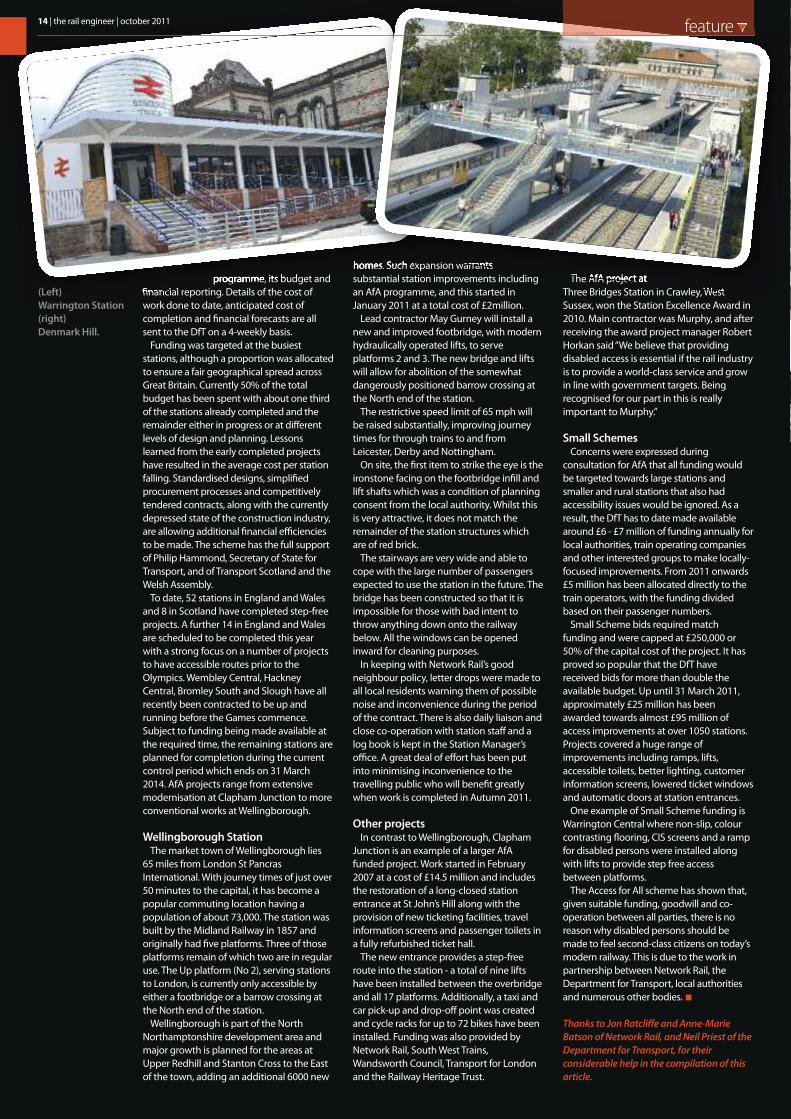
(Left) Warrington Station(right)Denmark Hill.
ugust 2011 saw the implementation ofthe latest series of improvements to the
Chiltern Railway’s Marylebone toBirmingham line. Bannered under the nameEvergreen 3, this stage is almost the finalprogramme of work to restore the route toits past glories.
The line has seen mixed fortunes overtime. One of the last railways to be built, itopened in 1906 as the GW&GC Joint line,itself linking up a series of other lines to forma rival to the LNWR route northwards fromLondon. The line was constructed with thelessons of avoiding flat junctions in mind,with Northolt, Ashenden and Aynho allhaving flyovers to minimise conflictingmoves. Principal stations had main linesthrough the middle with loops toaccommodate the platforms, Denham,Gerrards Cross, Beaconsfield, PrincesRisborough and Bicester North beingexamples.
The route settled down to providing aPaddington - Birmingham service as analternative to the WCML via Rugby, as well asenabling the GCR to have a second routeinto its Marylebone terminus. Birminghamwas around 2 hours from the capital by thebest trains, regardless of route. The GW routecame into prominence in the 1960s duringthe electrification of the West Coast MainLine with virtually all Birmingham trafficbeing put to the Paddington line.
Rationalisation and declineIn the aftermath of Beeching and the then
thinking that two lines between principalcities were not needed, the Great Westernroute suffered a downgrading. The GreatCentral northwards was closed, negating theneed for Ashenden Junction. Stationthrough lines were removed and the entireroute from Princes Risborough to Aynho(where it joined the GW Oxford - Banburyline) was singled having only a passing loopat Bicester. The remaining train service wasconcentrated on Marylebone with only onetrain per day running to Paddington.
Little more than an outer suburbanservice, trains were formed of ageing DMUsand reliability suffered accordingly. EvenMarylebone was considered for closure atone time, but the remaining traffic wassufficient to make it impractical toaccommodate at other termini. So the linesurvived, and with privatisation came therealisation that considerable untappedpotential was there for the taking.
Chiltern Railways and Evergreen 1Led by career railwaymen and women,
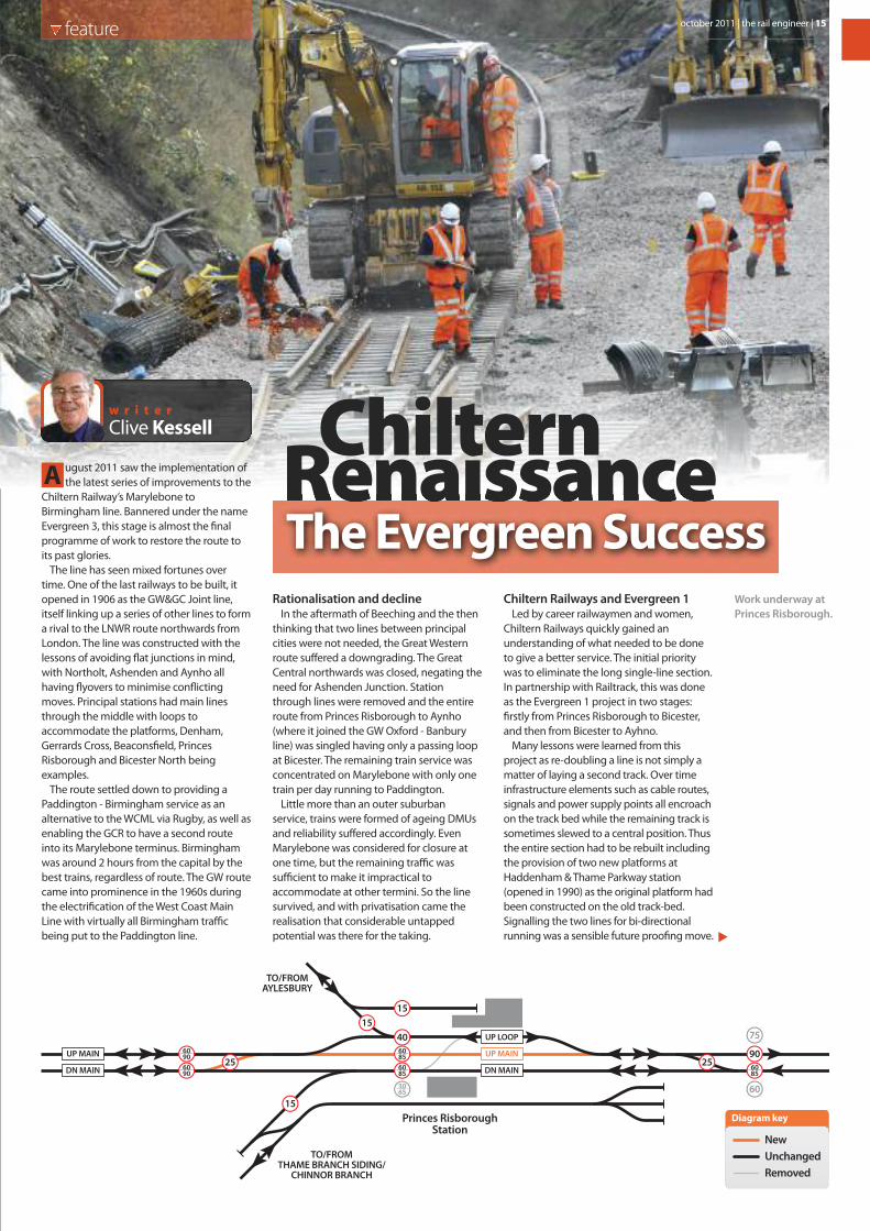
Chiltern Railways quickly gained anunderstanding of what needed to be doneto give a better service. The initial prioritywas to eliminate the long single-line section.In partnership with Railtrack, this was doneas the Evergreen 1 project in two stages:firstly from Princes Risborough to Bicester,and then from Bicester to Ayhno.
Many lessons were learned from thisproject as re-doubling a line is not simply amatter of laying a second track. Over timeinfrastructure elements such as cable routes,signals and power supply points all encroachon the track bed while the remaining track issometimes slewed to a central position. Thusthe entire section had to be rebuilt includingthe provision of two new platforms atHaddenham & Thame Parkway station(opened in 1990) as the original platform hadbeen constructed on the old track-bed.Signalling the two lines for bi-directionalrunning was a sensible future proofing move.
A
feature
RenaissanceChilternThe Evergreen Success
Clive Kessellw r i t e r
40
6085
9025
60856085
60906090
15
25
1515
75
603065
Princes RisboroughStation
UP MAIN
DN MAIN
UP LOOP
UP MAIN
DN MAIN
TO/FROMAYLESBURY
TO/FROMTHAME BRANCH SIDING/
CHINNOR BRANCH
Diagram key
NewUnchangedRemoved
Work underway atPrinces Risborough.
october 2011 | the rail engineer | 15

West RuislipStation South Ruislip
StationUP SIDINGS
DN SIDINGS
UP MAIN
UP LOOP
DN MAIN
DN LOOP
UP/DN MAIN
DN MAINUP MAIN
LUL
WASTETERMINAL
60100
60100
3560
3550
60
5040
25
15
15
6010060
100
3060
5575
6075
Diagram key
NewUnchangedRemoved
Work in progress -Neasden.
The concentration of traffic onto a singleplatform at Princes Risborough was anotherencumbrance and the down platform wasrestored at the same time, albeit without thethrough centre lines. While the cost wasconsiderable, restoring a two track railwaygave immediate benefits in timetablereliability.
Evergreen 2The increasing train service required
additional capacity at Marylebone, so, underthe Evergreen 2 project, that terminus wasgiven another 2 platforms making 6 in total,something it had never had in its entirehistory. With new Networker Turbo trainscoming on stream, the opportunities forexpanding services beyond Banbury becameobvious and in association with Centro, whowere busy restoring Birmingham Snow Hilland providing through platforms atBirmingham Moor St, sufficient capacity wasavailable for Chiltern Railways to run toBirmingham.
Evergreen 2 also included the provision of anew train servicing depot at Wembleytogether with speed improvements atBeaconsfield and various signallingmodifications. However, this was not the endof the story as overall journey times neededto be reduced still further to compete withboth the WCML and the M40.
Evergreen 3 A critical appraisal of options revealed that
work at seven locations was necessary to getthe much needed line speed improvements.All have now been implemented.• Aynho Junction. The 50mph turnouts for
the Marylebone line have been raised to90mph in the up direction and 85mph for
the down line coming off the flyover withnew high speed points connecting to theOxford lines. In addition, a new facingcrossover makes the junction fullyreversible so that bi-directional working canbe implemented when necessary over theAynho to Princes Risborough line. Having a7 day railway is very much in the minds ofthe Chiltern Railways management, as wellas benefiting other operators using theDidcot to Chester line. The Aynho workswere completed in March 2011.
• Bicester. The removal of the old throughlines meant that the remaining runninglines were slewed over to the platforms,necessitating a speed restriction. In the up(London) direction, the platform has nowbeen built out so that the line can assumeits former straight alignment. This workwas also completed in March 2011 andresulted in an increase in linespeed from25mph to 100 mph.
• Princes Risborough.As at Bicester, theslewing of the up line to the platformalignment imposed a speed restriction. Inaddition, conflicts were caused by thebranch line services to Aylesbury alsousing that platform. Since the fastBirmingham services will not stop at thisstation, the solution has been to restorethe up through line with connections atboth ends for the platform line. Both uplines have been made reversible. This workwas done between 22 - 28 August.
• High Wycombe.A new positioning of thenorth end crossover enables higherspeeds to be achieved through the stationfor non stopping services.
• Gerrards Cross.The construction worksfor the artificial Tesco tunnel to facilitate astore car park needed a siding to beprovided for the works trains and theformer turnback siding was converted
temporarily as a freight facility. Theunfortunate collapse of the tunnel duringthe work was an unwanted hindrance butled to one wag coining the phrase ‘Youshop, We drop’. With the incident now wellin the past, the opportunity has beenseized to future-proof the siding andextend it to create an 8-car turnbackfacility for inner suburban services.Another turnback has been provided fromthe platform on the down line.
• Northolt Junction.The grade-separatedjunction favoured the ex-GW line toPaddington for higher speed. However,with virtually all services now concentratedon Marylebone and the GW route reducedto a single line, this situation needed to beremedied. The solution has been toconstruct a new double track formationdirect from Northolt to South Ruislip,retaining the fly-under route for suburbantrains needing to stop at Ruislip, with theGW line routed via a single lead connectionand facing crossover. The civil works toconstruct the double track alignment havebeen complex and were described in theMarch and August 2011 editions of the railengineer. The work was completed duringa blockade lasting from 22 - 28 August.
• Neasden Junction.Where the Amershamand Banbury lines diverge, the doublejunction restricted the latterlines to 40mph. The junctionhas now been remodelled asa series of single leads topermit a 75mph turnouttowards Banbury. Thiswork was carried outbetween 12and 21
Track diagramat Northolt.
16 | the rail engineer | october 2011 feature
www.bamnuttall.co.uk
Successful delivery of Project Evergreen 3
The upgrade of the Chiltern Mainline between London Marylebone and Birmingham Moor Street is complete allowing trains to travel at 100mph and reducing travel time to 90 minutes.
A team led by BAM Nuttall has delivered this complex and high profi le upgrade, which involved extensive trackwork, signalling and structures renewal.
Offering total rail capability BAM Nuttall has a justifi ed reputation for developing collaborative relationships with our clients including Network Rail, Train Operating Companies, London Underground and Transport for London.
Our areas of expertise cover:
• Permanent Way • Signalling and telecommunications • Structures maintenance/renewal • Stations and depots • Geotechnical engineering
BAM Nuttall is committed to offering real value to our clients and working with them in close and lasting co-operation.
Trevor Maginley
0203 205 [email protected]

18 | the rail engineer | october 2011 feature
August during a total blockade.Mention must also be made of
Birmingham Moor Street, where, after manymonths of waiting, signalling works werecompleted in November 2010 to bring intouse the bay platforms. Chiltern Railways usethese for some services as capacity at thethree platform Snow Hill station (the 4thplatform being used for Midland Metro tramservices) is limited.
The two stations contrast greatly, withMoor St being a classic design in true GWstyle while Snow Hill is a stark concreteedifice that compares badly to thearchitectural gem that was the originalstation.
Finance and ContractsThe Evergreen 3 project is unusual since it
is an infrastructure improvement, but withfinancing coming entirely from ChilternRailways. They are the Sponsor, Client andAgent. Network Rail has been a co-sponsorbut also has the role of mortgagor andapprover.
Costing around £250m, the justificationcentred on the additional passengernumbers and income that the scheme willgenerate. Whilst the prime work has been toprovide additional trackwork, the projecthas involved a number of engineeringdisciplines. Chiltern appointed BAM Nuttallas lead contractor to have a design and build
responsibility as well as letting andmanaging all the principal sub contracts.These were:• Civil Works - BAM Ritchies constructed the
Northolt double track formation.• Trackwork - Although Colas initially stood
in after Jarvis ceased to trade, BAM Nuttallundertook much of the trackwork on theirown account. Balfour Beatty carried outthe work at Aynho. On-track machines andplant were provided by Colas, BalfourBeatty and Babcock Rail
• Signalling - Atkins was responsible for thedesign, installation and testing of allexternal signalling alterations. Theseincluded the re-signalling of thejunction areas as described plusthe provision of many new signalsmainly between High Wycombeand London to give greaterspacing for the higher line speeds.All new signals are of the LED type.Preliminary Route Indicators(PRIs) were also installed togive advance warning ofthe direction to be takenat the higher speed junctionsby means of lit right or leftarrows prior to theflashing yellow aspect.
• Marylebone IECC - DeltaRail,who as BR Research andAEA Technology werethe developers ofIntegrated ElectronicControl Centresand had the
UP MAIN
DN MAIN
UP MAIN
DN MAIN
UP HARROW
DN HARROW
FREIGHT TERMINAL
SIDINGS
SIDINGS
TONEASDEN
JNC
Neasden South Junction
15
3065
3050
3050
3070
3075
3070
3060
3075
3070
15
6085
6085
6010060
100
15
3060
Diagram key
NewUnchangedRemoved
Birmingham MoorStreet Station.
Bicester North.
october 2011 | the rail engineer | 19feature
For further information about how Hydrex can help you:
Telephone: 01275 399400 Email: [email protected]
With a network of depots across the UK, Hydrex is uniquely
placed to offer a combination of national coverage,
consistency, local knowledge and expertise.
Our passion for customer satisfaction, together with our
focus on compliance and delivery excellence, ensures
that Hydrex can offer repeatable and reliable services
for customers.
Our Rail Solutions:
• RRV and operator hire to support all aspects of Track
Maintenance, Renewals and Enhancement work
• Plant Operator Licence Services – total support in the
planning, organisation and control of RRV operations
• Contract lifts and development of lift plans
• Solutions for Piling, Drainage, Vegetation Clearance,
Earthworks, OLE & Signalling requirements
Workingin partnership with UK Rail
expertise to make the necessarychanges to the MaryleboneSignalling Centre from which themajority of the route is controlled.This involved the provision of a thirdcomplete SSI interlocking as therewas insufficient capacity within theexisting ones to accommodate thechanges. Some re-mapping ofsignalling boundaries between theinterlockings took place at the sametime. Changes to the train describerfunction and the associated cabsecure radio link also had to beundertaken.
• Telecoms - telent undertook all thework associated with cable alterationsand new or re-located SPTs.
• ATP - Alcatel supplied the originalSELCAB equipment to the Chilternsroute, one of two BR trial AutomaticProtection Systems in the early 1990s(the other was on the GW main line)as a forerunner of TPWS and ERTMS.The system extended only fromMarylebone to Banbury. Thales, assuccessors to Alcatel, supplied newequipment and Atkins designed andinstalled the inductive loops, whichincluded lengthening some existingloops to comply with the requiredstandard.
As co-sponsors, Chiltern Railways andNetwork Rail staff have been engagedin the supervision and monitoring ofthe overall project.
Impact of the BlockadesHaving to close a line to carry out
work is disruptive and ChilternRailways have been very careful tominimise inconvenience to the public.During the Neasden works,passengers for the Amersham /Aylesbury line had to change atHarrow and use the LU MetropolitanLine service. A Chiltern service fromBicester and High Wycombe operatedto Paddington with First GreatWestern cancelling their PaddingtonGreenford service so as to providesufficient capacity between Old OakCommon and Paddington.Birmingham trains were diverted to
Didcot with passengers changing toFGW to reach London.
The Wembley to Princes Risboroughpossession required an element of bussubstitution with passengers for theHigh Wycombe area using buses fromAmersham, and those for Bicesterbeing provided with a bus service fromthe new Aylesbury Vale station.Passengers at stations in the innerLondon area had a choice of substitutebuses or local LU services.
The pain was relatively short and withmany people on holiday, the Chilternmanagement took the view that a ‘bigbang’ approach with sensible use ofblockades was preferable to even moreweekend closures.
The Achievement and the FutureWith all work being completed by 30
August, Chiltern Railways had a week tolearn how to use the revised layoutbefore introducing its new timetable onSeptember 5th. This gave a 100mphcapability over most of the routeenabling a fastest time from Maryleboneto Birmingham of 90 minutes with twointermediate stops, at Solihull andWarwick Parkway. Every hour a serviceruns with a 100 minute schedule withadditional stops at Leamington Spa andBanbury. That is nearly as quick as theWCML and perhaps more convenient forthe sizeable populations of towns alongthe route.
Evergreen 4?This part of Evergreen 3 is however
not the end of the story. Part 2 of theproject will provide the muchpublicised new chord at Bicester, a newparkway station for north Oxford atWater Eaton Parkway and an alternativeservice from London to Oxford, alsoproviding journey opportunitiesbetween High Wycombe, Bicester andOxford. The ministerial go-ahead of thescheme is expected by the end of 2011with design and construction worktaking place in 2012/3 and the newservice being in operation from 2014.This will be another story and the railengineer looks forward to following itsprogress.

20 | the rail engineer | october 2011 feature
ne of the manydefinitions for the
word “Innovation” is “theintroduction of newtechnology that addsvalue”. Over 150 yearsago, the early railwaysproved themselves to be
a most successful innovation by creating ahuge increase in economic activity fromsignificantly improved transport. However,as with all things, the world moves on andunfortunately Great Britain’s railways are notas good at innovation today.
That is the conclusion reached by Sir RoyMcNulty’s study “Realising the potential ofGB rail”. This value-for-money studyconcludes that Britain’s railways areunderperforming in innovation because of
industry fragmentation, the need forimmediate returns, an absence of incentivesto innovate, a lack of a managementstructure to drive innovation, the restrictiveapplication of standards undermininginnovation, the lack of suitable test facilitiesand insufficient investment in research anddevelopment. McNulty concludes thatimprovements in safety, standards andinnovation could save £190 million by2018/19 or between 18 and 26% of the totalestimated savings from recommendations inhis report. Sir Roy’s findings are supportedby a study undertaken by Atkins entitled“Improving Management & Delivery ofInnovation”, which is essential reading foranyone with an interest in UK rail innovation.
Network Rail’s new approachSo how is Network Rail responding to
McNulty’s innovation challenge? In anexclusive interview with the rail engineer,Steve Yianni, Network Rail’s Chief Engineer(pictured left), sets out his strategy toimprove innovation in Network Rail andexplains how, in some areas, it has pre-empted Sir Roy’s recommendations.
Steve opened by stating “For some timeNetwork Rail has recognised that there areissues with the way it introduces newtechnology and that an improved approachis required to improve processes andincrease supplier engagement”. Heexplained that, early in 2010, Network Railstarted to compare the way it introducedtechnology both with other parts of the railsector and with other industries. From this
comparison a new process was developedand piloted, starting first with 10 andeventually with 56 projects. The process wasthen finalised on the basis of feedback fromusers, external parties, stakeholders andlaunched in February 2011.
Network Rail’s new innovationprocess consists of four stagesThink
Ensure that the problem is understood toestablish a clear business need as previouslyproducts had been developed when therewasn’t one. A Network Rail sponsor isidentified to drive product development. Explore
Establish a preferred solution through aform of brainstorming process. This exploresand tests potential solutions on a cross-discipline basis. Prove
Develop the preferred solution to thestage when it can be tested to demonstratethat the design intent is met, including anynecessary safety approvals.Do
Implement, ensuring that all necessarysupport, training and resources are in placeand that all concerned know of the newproduct.
O
David Shirresw r i t e r
ChallengeInnovationThe
(Above) Aninstallation of theinnovativeRamArch Systemby ISS in WhiteballTunnel.
Network Rail puttogether atemporary stationat Workington lastyear within 4 days.

october 2011 | the rail engineer | 21feature
Steve acknowledged that, previously,suppliers wanting to develop new productshad found communication with NetworkRail difficult. Often, ideas were offered butsuppliers did not know how to progressthem. Even if a Network Rail contact wasfound, they frequently developed thingswhich went nowhere. This was clearly asignificant disincentive to innovate andshowed the need for the improved supplierengagement that is now an integral part ofNetwork Rail’s strategy.
Matching ideas to business need“Network Rail seeks bright ideas with
matchmaking website” was the title of apress release on 14 February this year as partof the launch of the new innovation process.This invited suppliers to submit their ideas toits bright ideas website,www.networkrail.co.uk/brightideas.
To ensure that submitted ideas meet aclear business need, the website listsNetwork Rail’s 16 Challenges and Prioritiesfor which innovation is required. Moreover,the first question on the online innovationand suggestions form is “which challengedoes your solution relate to?”.
Steve explained that this list of challengeshas been developed by cross-functionalinnovation portfolio groups which meet toreview input from suppliers and refreshchallenges. This is clearly an ongoingprocess as, for example, there are currentlyno signalling challenges. The portfoliogroups also provide suppliers with feedbackon their ideas.
The process is not restricted to externalsuppliers. There is a similar scheme tocapture ideas from Network Rail’s employeesand encourage them to think about thechallenges.
Although the new process does notchange product acceptance requirements, ithas been possible to speed up the processby reducing the number of products
requiring approval. Much of the backlog didnot meet the business need established bythe “Think” stage of the process. In addition,simple approvals are now delegated to amore appropriate level, e.g. route assetmanagement, and many product approvalsare what Steve described as “cataloguemanagement” and can be processed morequickly.
• Planning for using mobile plant -measuring gradient
• Reducing noise emitted from plant• Safety Innovation• Condition Monitoring of Buildings &
Civils assets• Greater business benefit from waste• Improved power supply and energy
efficiency• Low cost fault reporting• Planning for climate change
• Protective coatings for metallicstructures
• Remote condition monitoring of trackassets
• Remote monitoring of electrical powerassets
• Alternative (remote) earthing systems• Retro-waterproofing tunnel linings• Track components• Reducing reliance on copper• Track system renewal
Network Rail’s 16 Innovation Challenges and Priorities
VMS has created asystem of super
lightweight Signals &Structures, which
won Network Rail’sAward for Innovation.
Innovative Support Systems Ltd15 Fountain Parade, Mapplewell, Barnsley, S. Yorks. S75 6FW, UK.
Tel: +44 (0) 1226 381155, Fax: +44 (0) 1226 381177e-mail: [email protected], website: www.iss-eng.com
R W
R
W
B
R
AM ALL FOR
ETAINING
ALLS, &
ALLAST
ETENTION
R A T
S & B
AM RCH FOR UNNELS
HAFTS RIDGES
,

22 | the rail engineer | october 2011 feature
The Atkins report takes Network Rail’sInnovation Management System as a casestudy. It considered a particularlyencouraging aspect of the system to becollaboration and early engagement withsuppliers, and noted how Network Rail hasdeployed dedicated innovationmanagement staff and increasinginnovation management capacity by
delegating authority,although withvarying success
between disciplines.
StandardsThe McNulty report
commented on the largenumber of standards thatoften conflict with each other.These create excessive costand delay and havesometimes prevented theimplementation of specificinitiatives. The reportconcluded that this wassymptomatic of the widerissue of an industry notlooking at technical issues ona system-wide basis and tooreliant on blind compliancewith established standards.Although such system-widequestions are the remit of thenew Rail Systems Agency,Steve explained how NetworkRail is taking action tominimise the impact ofstandards on innovation. Heagrees with McNulty thatstandards are sometimesused as an excuse, and
accepts that some are nolonger appropriate as
technology has movedon since the standard
was written.Steve Yianniacknowledges
that thecontract
awards procedure hasalso resulted inunnecessary constraints.Contractors are nowencouraged to submit anon-compliant bid if thisoffers advantages,particularly if it addressesone of the 16 Challengesand Priorities. “You tell uswhy that’s better” isSteve’s message tocontractors. This approach is supported byNetwork Rail’s Procurement community whohave been actively involved in the newtechnology process. If justified, derogationsto Network Rail standards can be quicklyobtained. Steve acknowledges thatderogations to Group Standards are morechallenging and the McNulty reportacknowledges that this is a lengthy process.Thus, until the Rail Systems Agency resolvesthis issue, bids that don’t comply with GroupStandards bids will probably fail.
However, Network Rail’s engineeringstandards have all been reviewed with eachrequirement classified as: Red - an absoluterequirement; Amber - stronglyrecommended but derogation could beissued if sufficient justification and Green -best practice guidance but not compulsory.Steve explained that this process supportsdevolution and is being piloted in therecently devolved routes where it has hadpositive feedback. The concept is beingshared with other parts of the industry withthe intent that it be applied to GroupStandards. It is likely that Steve will get hiswish in this respect as, interestingly, theMcNulty report recommends the Red,Amber and Green process that has alreadybeen applied to Network Rail’s standards.
Research and DevelopmentSuccessful innovation requires an effective
Research and Development programme.McNulty concludes that the rail industry’scurrent £34 million per year R&Dprogramme lacks the structure to driveinnovation across the industry and that R&D
expenditure should increase to £75 millionby 2018/19. Steve would agree with theneed to increase R&D spend, but points outthat Network Rail is actively promoting R&Dand is spending around £18 million perannum. It is working with a number ofuniversities, including the funding of severalChairs, has strategic relationships withImperial College, Nottingham and SheffieldUniversities, and each year runs a conferenceon its research activities.
Network Rail also has its Rail Innovationand Development Centre, a 10 mile testtrack in Nottinghamshire which is availablefor the whole of the rail industry. This goessome way to address McNulty’s concernabout the lack of British test facilities.
Network Rail’s journeyReviewing progress so far, Steve Yianni
described the way that Network Rail hasencouraged the introduction of newtechnology as “a journey that Network Railhas been on over the last 18 months”. So itis, and not before time. In December 2009,New Civil Engineer published a criticalarticle that “slammed the rail infrastructuremanager’s claims that it fosters innovation”and complained that insufficient guidancewas given for innovative products.
Such criticisms no longer apply now thatNetwork Rail has streamlined its processesand is actively engaged with its suppliersusing its website to marry ideas tobusiness needs. It is also changing itsapproach to standards and promoting R&Dincluding the introduction of new testfacilities. All of which is in tune withMcNulty’s approach to innovation. IndeedAtkins’ innovation report includes a graphshowing that Network Rail has the highestinnovation index of any part of the UK railindustry.
A good start has been made but there isstill some way to go, particularly in respectof system-wide issues outside NetworkRail’s direct control. It will be fascinating tosee where this journey takes the UK railindustry.
(Above) TheHarrington Hump,(right) BalfourBeatty’s innovativeAir InsulatedSwitchgear,(below) Peli 9440takes seconds todeploy and extendsthe light above twometres.
october 2011 | the rail engineer | 23feature
!"#
!!"#$% "!"!&%'(&)"#(
$%&'%(")*+() ,$), *(+-+) !$.("/*+*0,"'&*1)
!"#$%$&'"!($)!*+,#'"-.$/,#-#0$ 110'$)23!"0.*$4-5$
&'"!(6$70'#,8$79:;$%<=$&0.>$?@%%:$A:A;AB
0C-".>$1D*E".02,5,82F8+3GGG8".02,5,82F8+3
!""#$%&'()*+,-./
#23+)4567+ 89:12+&;8<75<;<=5"<=>5;95?+(;657@
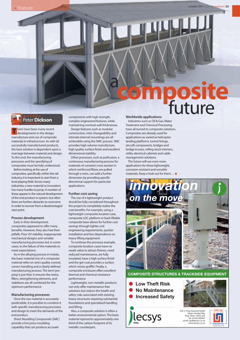
here have been many recentdevelopments in the design,
manufacture and use of compositematerials in infrastructure. As with allsuccessfully manufactured products,the best solution is dependent upon amarriage between material and design.To this end, the manufacturingprocesses and the specifying ofcomposites must be fully understood.
Before looking at the use ofcomposites, specifically within the railindustry, it is important to start from alevel playing field. Across manyindustries, a new material or innovationhas many hurdles to jump. A number ofthese appear in the natural developmentof the end product or system, but oftenthere are further obstacles to overcomein order to recover from a disadvantagedstart point.
Process developmentEarly in their development,
composites appeared to offer manybenefits. However, they also had theirpitfalls. Poor UV stability, inappropriatemechanical designs and variablemanufacturing processes led, in somecases, to the failure of the materials tomeet expectations.
As in the alloying process in metals,the basic material mix of a compositematerial relies on strict quality control,correct handling and a clearly definedmanufacturing process. The term ‘pre-preg’ is just that. It ensures the resins,fillers, strengthening elements, andstabilisers are all combined for theoptimum performance.
Manufacturing processesOnce the raw material is accurately
predictable, it is possible to combine itwith specific manufacturing processesand design to meet the demands of theend product.
Sheet Moulding Compounds (SMC)provide a hot press mouldingcapability that can produce accurate
components with high strength,complex engineered features, whilemaintaining nominal wall thicknesses.
Design features such as modularconstruction, inter changeability andintricate internal mountings are allachievable using the SMC process. SMCprovides high volume manufacture,high quality surface finish and excellentdimensional stability.
Other processes, such as pultrusion, acontinuous manufacturing process formaterials of constant cross-section inwhich reinforced fibres are pulledthrough a resin, can add a furtherdimension by providing specificdirectional support for particularapplications.
Further cost savingThe use of a lightweight product
should be fully considered throughoutthe project to completely realise thecost benefits. For example, using alightweight composite location case,composite LOC platform or back-fillablecomposite base allows for further costsavings through lighter civilengineering requirements, quickerinstallation and less dependence onheavy lifting equipment.
To continue the previous example,composite location cases have noresale value to attract thieves, needreduced maintenance, are fullyinsulated, have a high surface finishand the gel-coat provides a surfacewhich resists graffiti. Finally, acomposite enclosure offers excellentthermal and chemical resistanceperformance.
Lightweight, non-metallic productsnot only offer maintenance-freesolutions but reduce the health andsafety risks associated with existingheavy structures requiring substantialfoundations and specialised handlingand lifting.
Also, a composite solution is often abetter environmental option. The basicmaterial represents approximately onethird of the carbon footprint of itsmetallic counterpart.
Worldwide applicationsIndustries such as Oil & Gas, Water
Treatment and Chemical Processinghave all turned to composite solutions.Composites are already used forapplications as varied as helicopterlanding platforms, tunnel linings,aircraft components, bridges andbridge trusses, rolling stock interiors,utility electrical cabinets and cablemanagement solutions.
The future will see even moreapplications for these lightweight,corrosion-resistant and versatilematerials. Keep a look out for them…
T
Peter Dicksonw r i t e r
Director, iLecsys
compositefuture
a

ven in the halcyon days of mechanicalsignalling, with 10,000 signal boxes on
the network, it was far from common to findtwo boxes facing each other across thetracks. But a new signalling scheme,commissioned over the August BankHoliday in Rochdale has brought about justthis situation. Two fully operational signalboxes, the pre-existing Castleton EastJunction and the newly opened RochdaleWest signal boxes, are now happilysignalling trains to each other, and yet theylie just 100 yards apart.This is not an interim measure; these twosignal boxes will remain operational for theforeseeable future. There is of course arational, if unusual, reason for the fact thatthe two signallers are within shoutingdistance. And no, it is not Network Rail’slatest answer to the cable theft problem!
Metrolink extensionUntil recently, the Oldham Loop Line
joined the Manchester and Leeds (CalderValley) route at Rochdale. The sectionbetween Oldham Mumps and Rochdale hashad a checkered history. In May 1972 theMinister for Transport announced that this
section of the Oldham Loop would beclosed. Fortunately it was reprieved whenthe SELNEC Passenger Transport Executive(later the Greater Manchester PTE) agreed tofund the train services. The track washowever singled between Shaw &Crompton station and Rochdale.
On 3rd October 2009 the line did close, butthis time the reason had nothing to do withcutbacks. The line is now being rebuilt as anextension of the Manchester Metrolinksystem, destined to serve Rochdale towncentre and due to open in the summer of2012. The original junction at Rochdale hasbeen retained and now forms a turnbacksiding for Northern’s Rochdale-Manchesterservices, as well as giving heavy rail workstrains access to the Metrolink system.
To reach Rochdale town centre, theMetrolink line has been extended beyond theOldham Loop formation and passes over theCalder Valley line on a new flyover bridge. Thiswas constructed by M-Pact Thales,contractors to Transport for GreaterManchester (TfGM). The Metrolink route thencontinues towards the town by runningparallel to the Network Rail tracks on the bedof an old loop line. It then leaves the railwayalignment to follow what was High LevelRoad before arriving at the site of a tram andbus interchange station right outsideRochdale train station. Unfortunately one
building, Rochdale signal box, stood in theway of progress. So, this 1889 built Lancashire& Yorkshire Railway structure would have tobe demolished. In addition, track circuits and
E
Stuart Marshw r i t e r
Rochdalegoes west
feature24 | the rail engineer | october 2011
(Right)Now demolished,the originalRochdale box.
Adjacent toRochdale Station thenew Metrolink linefollows High LevelRoad, now closed toroad traffic.
URS Scott Wilson Ltd was appointed asthe multi-disciplinary GRIP 4 designer forMetrolink Phase 3A in 2008. Since then,GRIP 5 designs for the severance of theOldham loop at Rochdale have alsobeen successfully delivered. The GRIP 5designs for phase 1 of Rochdale Westinvolved signalling, permanent way,telecommunications, E&P, geotechnical,civil engineering and architecturedisciplines using engineering teamsfrom URS Scott Wilson’s Crewe, York,Glasgow, Swindon, Middlesbrough andNottingham offices.
The unusual delivery method forphase 1 required URS Scott Wilson toprovide design support over thecommissioning weekend, workingalongside Network Rail’s project andinstallation teams.
Ian Hay, Director for Heavy Rail, said“We have been very pleased to haveplayed our part in the successfulcommissioning of phase 1. As always,there were a few difficult hurdles toovercome along the way. However thestrong team spirit apparent between ourrespective teams ensured that weachieved an on time success. We lookforward to working with Network Rail onthe next phase of the scheme.”
Design for success
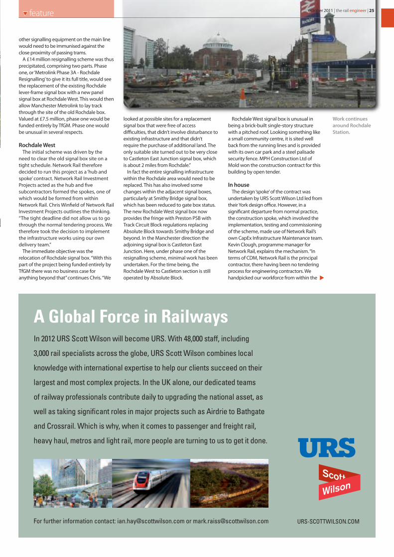
other signalling equipment on the main linewould need to be immunised against theclose proximity of passing trams.
A £14 million resignalling scheme was thusprecipitated, comprising two parts. Phaseone, or ‘Metrolink Phase 3A - RochdaleResignalling’ to give it its full title, would seethe replacement of the existing Rochdalelever-frame signal box with a new panelsignal box at Rochdale West. This would thenallow Manchester Metrolink to lay trackthrough the site of the old Rochdale box.Valued at £7.5 million, phase one would befunded entirely by TfGM. Phase one wouldbe unusual in several respects.
Rochdale WestThe initial scheme was driven by the
need to clear the old signal box site on atight schedule. Network Rail thereforedecided to run this project as a ‘hub andspoke’ contract. Network Rail InvestmentProjects acted as the hub and fivesubcontractors formed the spokes, one ofwhich would be formed from withinNetwork Rail. Chris Winfield of Network RailInvestment Projects outlines the thinking.“The tight deadline did not allow us to gothrough the normal tendering process. Wetherefore took the decision to implementthe infrastructure works using our owndelivery team.”
The immediate objective was therelocation of Rochdale signal box. “With thispart of the project being funded entirely byTfGM there was no business case foranything beyond that” continues Chris. “We
looked at possible sites for a replacementsignal box that were free of accessdifficulties, that didn’t involve disturbance toexisting infrastructure and that didn’trequire the purchase of additional land. Theonly suitable site turned out to be very closeto Castleton East Junction signal box, whichis about 2 miles from Rochdale.”
In fact the entire signalling infrastructurewithin the Rochdale area would need to bereplaced. This has also involved somechanges within the adjacent signal boxes,particularly at Smithy Bridge signal box,which has been reduced to gate box status.The new Rochdale West signal box nowprovides the fringe with Preston PSB withTrack Circuit Block regulations replacingAbsolute Block towards Smithy Bridge andbeyond. In the Manchester direction theadjoining signal box is Castleton EastJunction. Here, under phase one of theresignalling scheme, minimal work has beenundertaken. For the time being, theRochdale West to Castleton section is stilloperated by Absolute Block.
Rochdale West signal box is unusual inbeing a brick-built single-story structurewith a pitched roof. Looking something likea small community centre, it is sited wellback from the running lines and is providedwith its own car park and a steel palisadesecurity fence. MPH Construction Ltd ofMold won the construction contract for thisbuilding by open tender.
In houseThe design ‘spoke’ of the contract was
undertaken by URS Scott Wilson Ltd led fromtheir York design office. However, in asignificant departure from normal practice,the construction spoke, which involved theimplementation, testing and commissioningof the scheme, made use of Network Rail’sown CapEx Infrastructure Maintenance team.Kevin Clough, programme manager forNetwork Rail, explains the mechanism. “Interms of CDM, Network Rail is the principalcontractor, there having been no tenderingprocess for engineering contractors. Wehandpicked our workforce from within the
october 2011 | the rail engineer | 25feature
Work continuesaround RochdaleStation.
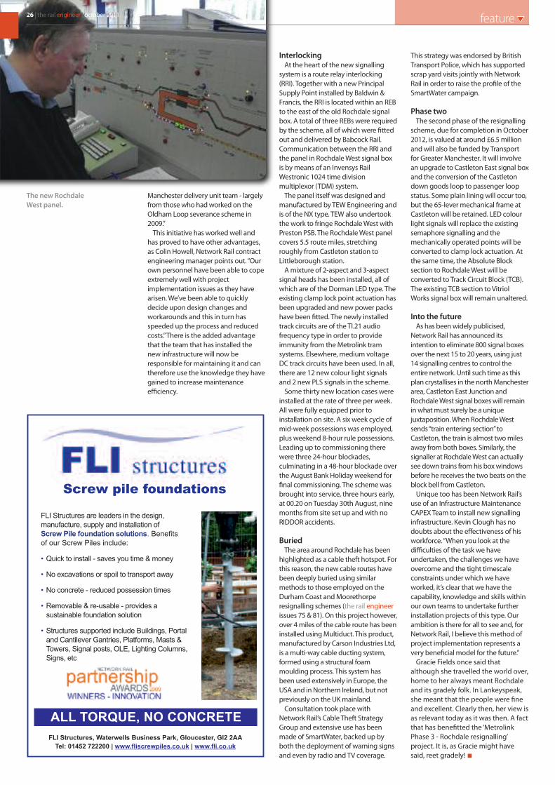
Manchester delivery unit team - largelyfrom those who had worked on theOldham Loop severance scheme in2009.”
This initiative has worked well andhas proved to have other advantages,as Colin Howell, Network Rail contractengineering manager points out. “Ourown personnel have been able to copeextremely well with projectimplementation issues as they havearisen. We’ve been able to quicklydecide upon design changes andworkarounds and this in turn hasspeeded up the process and reducedcosts.” There is the added advantagethat the team that has installed thenew infrastructure will now beresponsible for maintaining it and cantherefore use the knowledge they havegained to increase maintenanceefficiency.
InterlockingAt the heart of the new signalling
system is a route relay interlocking(RRI). Together with a new PrincipalSupply Point installed by Baldwin &Francis, the RRI is located within an REBto the east of the old Rochdale signalbox. A total of three REBs were requiredby the scheme, all of which were fittedout and delivered by Babcock Rail.Communication between the RRI andthe panel in Rochdale West signal boxis by means of an Invensys RailWestronic 1024 time divisionmultiplexor (TDM) system.
The panel itself was designed andmanufactured by TEW Engineering andis of the NX type. TEW also undertookthe work to fringe Rochdale West withPreston PSB. The Rochdale West panelcovers 5.5 route miles, stretchingroughly from Castleton station toLittleborough station.
A mixture of 2-aspect and 3-aspectsignal heads has been installed, all ofwhich are of the Dorman LED type. Theexisting clamp lock point actuation hasbeen upgraded and new power packshave been fitted. The newly installedtrack circuits are of the TI.21 audiofrequency type in order to provideimmunity from the Metrolink tramsystems. Elsewhere, medium voltageDC track circuits have been used. In all,there are 12 new colour light signalsand 2 new PLS signals in the scheme.
Some thirty new location cases wereinstalled at the rate of three per week.All were fully equipped prior toinstallation on site. A six week cycle ofmid-week possessions was employed,plus weekend 8-hour rule possessions.Leading up to commissioning therewere three 24-hour blockades,culminating in a 48-hour blockade overthe August Bank Holiday weekend forfinal commissioning. The scheme wasbrought into service, three hours early,at 00.20 on Tuesday 30th August, ninemonths from site set up and with noRIDDOR accidents.
BuriedThe area around Rochdale has been
highlighted as a cable theft hotspot. Forthis reason, the new cable routes havebeen deeply buried using similarmethods to those employed on theDurham Coast and Moorethorperesignalling schemes (the rail engineerissues 75 & 81). On this project however,over 4 miles of the cable route has beeninstalled using Multiduct. This product,manufactured by Carson Industries Ltd,is a multi-way cable ducting system,formed using a structural foammoulding process. This system hasbeen used extensively in Europe, theUSA and in Northern Ireland, but notpreviously on the UK mainland.
Consultation took place withNetwork Rail’s Cable Theft StrategyGroup and extensive use has beenmade of SmartWater, backed up byboth the deployment of warning signsand even by radio and TV coverage.
This strategy was endorsed by BritishTransport Police, which has supportedscrap yard visits jointly with NetworkRail in order to raise the profile of theSmartWater campaign.
Phase twoThe second phase of the resignalling
scheme, due for completion in October2012, is valued at around £6.5 millionand will also be funded by Transportfor Greater Manchester. It will involvean upgrade to Castleton East signal boxand the conversion of the Castletondown goods loop to passenger loopstatus. Some plain lining will occur too,but the 65-lever mechanical frame atCastleton will be retained. LED colourlight signals will replace the existingsemaphore signalling and themechanically operated points will beconverted to clamp lock actuation. Atthe same time, the Absolute Blocksection to Rochdale West will beconverted to Track Circuit Block (TCB).The existing TCB section to VitriolWorks signal box will remain unaltered.
Into the futureAs has been widely publicised,
Network Rail has announced itsintention to eliminate 800 signal boxesover the next 15 to 20 years, using just14 signalling centres to control theentire network. Until such time as thisplan crystallises in the north Manchesterarea, Castleton East Junction andRochdale West signal boxes will remainin what must surely be a uniquejuxtaposition. When Rochdale Westsends “train entering section” toCastleton, the train is almost two milesaway from both boxes. Similarly, thesignaller at Rochdale West can actuallysee down trains from his box windowsbefore he receives the two beats on theblock bell from Castleton.
Unique too has been Network Rail’suse of an Infrastructure MaintenanceCAPEX Team to install new signallinginfrastructure. Kevin Clough has nodoubts about the effectiveness of hisworkforce. “When you look at thedifficulties of the task we haveundertaken, the challenges we haveovercome and the tight timescaleconstraints under which we haveworked, it’s clear that we have thecapability, knowledge and skills withinour own teams to undertake furtherinstallation projects of this type. Ourambition is there for all to see and, forNetwork Rail, I believe this method ofproject implementation represents avery beneficial model for the future.”
Gracie Fields once said thatalthough she travelled the world over,home to her always meant Rochdaleand its gradely folk. In Lankeyspeak,she meant that the people were fineand excellent. Clearly then, her view isas relevant today as it was then. A factthat has benefitted the ‘MetrolinkPhase 3 - Rochdale resignalling’project. It is, as Gracie might havesaid, reet gradely!
26 | the rail engineer | october 2011 feature
The new RochdaleWest panel.
FLI Structures, Waterwells Business Park, Gloucester, Gl2 2AA
Tel: 01452 722200 | |www.fliscrewpiles.co.uk www.fli.co.uk
ALL TORQUE, NO CONCRETE
FLI Structures are leaders in the design,
manufacture, supply and installation of
Screw Pile foundation solutions.
•
•
•
•
•
Benefits
of our Screw Piles include:
Quick to install - saves you time & money
No excavations or spoil to transport away
No concrete - reduced possession times
Removable & re-usable - provides a
sustainable foundation solution
Structures supported include Buildings, Portal
and Cantilever Gantries, Platforms, Masts &
Towers, Signal posts, OLE, Lighting Columns,
Signs, etc
Screw pile foundations

Invensys Rail’s control centre solutions provide efficient and total railway control.
We seamlessly integrate and optimise advanced traffic management, SCADA, traction and station management (e.g. CCTV and Passenger Information).
Our solutions have been successfully deployed all around the world, including London, Madrid, Vancouver, Hong Kong and Oslo, ensuring compliance with each country’s unique rules and regulations.
We support a wide range of operating concepts including ERTMS, CBTC and now our unique ROAME (Railway Operations Administration & Maintenance Environment). This makes us a true one stop shop, providing the safety, efficiency and capacity you need.
Invensys Rail brings together Westinghouse, Dimetronic and Safetran, the world’s most trusted and experienced names in signalling and train control.
Find out how we can help you succeed, visit www.invensysrail.com or call +44 (0) 1249 441441
With Invensys Rail it all comes together perfectly
Proud to be Network Rail’s Supplier of the Year 2011
$ $ $ $$$ $$$

ith the privatisation of the railwayindustry, a number of large civil
engineering firms moved into rail as a naturalexpansion of their business. With them camea host of smaller sub-contractors, somealready established and some newly created.Over the years, there have been severalshake-ups in the sector, with contractorseither merging or going out of business, untilwe have reached the somewhat stablesituation that we have today.
So it is good to look at one of thosemedium sized companies, a privately-ownedoperation that has weathered the stormsand reached its tenth anniversary.
The beginningGlobal Rail Construction was set up in
August 2001 by Marco Lombardelli andIvan Holloway. Marco has been involvedwith the railway industry for over twentyyears and is a Member of the Institute ofRailway Signalling Engineers. He worked forGEC Alstom for 14 years in variousapplication engineering, design, project
engineering and testing andcommissioning roles. He joined FinchpalmLimited in July 1997 to implement anddevelop its signalling division.
Ivan Holloway has worked in the railwayindustry for over twenty years. Followingthe management of a number of signallinginstallation projects, he is now an IRSELicensed Signalling Installation Managerand holds qualifications and experience inthe disciplines of civil engineering,construction and health & safety. He iscurrently responsible for directing anddeveloping the business of Global RailServices Limited in Ireland.
With their combined backgrounds, it isnot surprising that Global Rail Constructionstarted out on signalling projects. Withintwo months of being founded, thecompany was working for Interserve Rail onsignalling installation works on the DorsetCoast Re-Signalling Project, and wereundertaking cable route surveys andinstallation on behalf of McNicholas Rail onthe FTN Project.
Success in IrelandHowever, even at this early stage the
company was diversifying, both in terms ofwork and geographically. Ivan’s connectionsin Ireland led to a contract to provideretaining walls and hard standing, as well ascable renewals, for a section of the DART(Dublin) route between Pierce Street Stationand Shank Hill. This got Global RailConstruction into the Irish market, and alsointo doing some more traditional civilengineering works.
In the UK, Westinghouse, Amey Rail andFitzpatrick were added to the client base,and in 2004 the first direct business withNetwork Rail came along with a contract toundertake final gauging and acceptancetesting after work on points machines andrail grinding and replacement betweenPaddington, Oxford and Reading.
Large projects continued to come out ofIreland including platform resurfacing andrefurbishment at Heuston and LansdowneRoad, telecoms masts at various sites, a newstation car park at Arklow, and installing 57kmof cables and cable troughs for the DASHproject which increased rail capacity in theDublin area by 30%. Global Rail Constructionwas delivering a wide range of projects.
More growthAs time went on, the contracts became
larger, and so did the company. Now witharound 300 full-time employees splitbetween offices in Hatfield, Ipswich andDublin, and an exemplary safety anddelivery record, Global Rail Construction arecurrently involved with some of today’smajor rail projects on both Network Rail andLondon Underground infrastructure.
To improve control and deployment of itsdirectly employed workforce, the businessdeveloped its Labour Supply Division tobetter utilise the various skill sets of staff,most of whom hold dual competencies forNetwork Rail and LUL.
Global Rail Construction was now able toprovide turnkey packages of works includingdesign and build, installation andcommissioning services. For example, thecompany was tasked with the design,implementation, testing and commissioningof 44 track circuits associated with theresignalling of Thameslink. Existing AC trackcircuits were replaced with double-rail TI21(EBI 200) equipment which use audio-frequency tuned circuits. In addition 15location cases were designed, manufactured,installed, tested and commissioned to anextremely tight program.
W
SuccessG
loba
l28 | the rail engineer | october 2011 feature

Coventry and MoorthorpeIn May 2007, the company was appointed
sub-contractor to Westinghouse RailSystems Limited (now Invensys Rail) for thesignalling installation and civil design andbuild packages for the Coventry Area Re-Signalling Project. The signalling elementincluded delivery and installation of all four-foot equipment as well as the fit-out andinstallation of the control centre. On thecivils side, 33km of cable route was installedtogether with associated location and signalbases. The company also built various signalgantries and demolished two signal boxes.
Following on from that project came thedesign and build contract for theMoorthorpe Re-Signalling Project, also fromInvensys Rail. Works included the design andinstallation of 33 Signal bases, REB and PSPbases, 25 location areas, drivers’ walkways,platform stagings and retaining walls.Another two signal boxes were alsodemolished.
StationsGlobal Rail Construction have also
undertaken several projects for May GurneyRail including the complete refurbishmentof station platforms at Alexandra Palace,Stamford and Wellingborough. These worksincluded the installation of block paving,tactile strip and platform edge coping aswell as ducting and drainage.
During this period, Mansell awardedGlobal Rail Construction the sub-contract tocomplete the platform finishing and
block/brick works on four low-levelplatforms at the new station at Dalston onthe East London Line. The construction ofnew staff accommodation and service areaswere also included.
Successful alliancesAs a result of hard work and commitment,
Global Rail Construction has establishedlong-lasting and successful alliances withsome of the major organisations within theindustry. The company now has a record ofsuccessfully completing projects for IrishRail, Network Rail and London Underground.It provides the flexibility of satisfying itsclients’ requirements through either ‘labouronly’ or full turnkey sub-contract packagesof work and has established a reputation for
delivering to programme and budget whileprioritising quality and safety. The companyhas recently been awarded OHSAS 18001 forits Occupational Heath and SafetyManagement System (SMS) to complementprevious accreditations for ISO 9001 and14001.
So congratulations to Global RailConstruction, and to ten years serving theUK and Irish Rail Networks. As MarcoLombardelli states, the company “mixestraditional industry skills with innovation,within a flexible management style, todeliver safely the client’s needs to thehighest quality.”
Signalling solutionsto the railway industry
Global Rail Construction Limited is a totally
client-focused organisation that combines
consistent technical excellence and
innovative problem-solving with a real
passion for detail and safe delivery of
projects.
These qualities make GRCL one of the
foremost multi-discipline engineering
suppliers of civil and signalling services to
the UK and Irish rail industries.
Constructive in its approach, GRCL has the
knowledge, resources and personnel to
deliver accurately, safely, flexibly and with
total reliability, whatever the complexity or
length of the project.
Phone: 0870 990 4074
Email: [email protected]
www.grcl.co.uk
october 2011 | the rail engineer | 29feature

30 | the rail engineer | october 2011 feature
evel crossings are tricky things. Theoutwardly simple process of having a
road cross a railway line is actually moredifficult than you might think.
For a start, the road surface has to be safe.It should have the same skid resistance asthe rest of the road. It has to take linemarkings and those shouldn’t wear offparticularly quickly. From a railway point ofview, the crossing should be quick to install,and easily removed so that track can bemaintained.
Traditionally, various solutions have beentried. Asphalt can’t be removed easily, and iflaid into trays or troughs it can break up.Wood can be slippery when wet, and istime-consuming to remove and replace.
Early rubberAround 30 years ago, rubber-faced
crossing panels started to appear. One of theoriginal manufacturers of these was the UScompany Omni Rubber Products, and from1988 their distributor in Europe wasHoldFast Level Crossings Ltd, based inCheltenham. Peter Coates-Smith, HoldFast’sManaging Director, was attracted to theconcept of using rubber as it was a flexiblematerial which provided better shockabsorption and trackbed protection thantraditional concrete and asphalt surfaces. Itsaved the rail from electrolytic corrosion, itwas safe on electrified lines, did not crack orcrumble, and was less costly to install thanother surfaces.
However the basic design of materials,panels, fixings, surface and system structurelimited these advantages. The Omni systemwas designed for low-traffic intensity freightcrossings in America and failed to meetEuropean safety expectations for traffic-intensive locations and different rail gauges.During the lengthy evaluation process,several distinct disadvantages wereidentified with the system.
Improved systemIn 1997, HoldFast ended its distribution
agreement with Omni in order to develop anew system suited to the European market.Railtrack (now Network Rail), trackmanagement organisations, civil andsubcontractors, potential customers andtrack gangs contributed valuable feedbackfrom a range of perspectives.
HoldFast is now widely recognised withinthe industry as being instrumental inturning round the reputation of rubber levelcrossings. In 1998, it launched its innovativenew UK-manufactured system whichfeatured significant design improvementsdeveloped in direct response to suggestionsfrom the customer base.
As Peter later explained, “An inherentweakness of early rubber systems was theneed for a surface layer which was aweakness and could peel.Small panels and complicatedfixing systems furtherweakened the crossings.
“We engineered productionplant to manufacture panelsas 100% solid recycled blocksof rubber. We also made thedecision to reduce thenumber of components andmake the panels larger toreduce the number of jointsand improve stability. Thisdoes make the panels veryheavy but we introducedspecial HoldFast Lifting Pins tocounter this”.
InstallationThe new HoldFast crossings
were an immediate success.The modular rubber panelssimply dropped into place. A40 metre crossing could beinstalled or replaced in threehours without the need foroverhead electrical isolation.Crossings could be delivered
and off-loaded direct from themanufacturing plant to the installation siteon the day (or night) of installation.
HoldFast’s standard installation process isvery straightforward. The HoldFast CrossingSystem consists of panels which are 1.8m inlength. Two panels are designed for the four-foot, with cess, field or six-foot panels placedoutside the rails and retained by either aconcrete or PVC edge beam. The panels areheld together by a baseplate with ‘turrets’. Adifferent baseplate, with legs and turrets, isthen placed over a sleeper at the centre lineof the road, retaining the crossing in place.At either end, a deflector plate is placed inthe middle of the gauge area.
The HoldFast panels can be removed fortrack maintenance, such as tamping, just aseasily. The speed of routine removal andreplacement of rubber crossings is no betterillustrated than at a particularly complexcrossing at Gloucester. The five trackcrossing comprised many full depth panels,but it took just two and a quarter hours toremove and stack two of those tracks priorto tamping them and no longer to replace.
The contractor lifted out the panels using apry bar on each of the panels and, with justone man on each, they levered the panelsout without any mechanical assistance. Theywere then numbered and stacked and with
L
HoldFast has supported the rail engineer inevery issue for the last seven consecutiveyears. We take a look back on selectedHoldFast developments over those years.
7 years and still holding fast
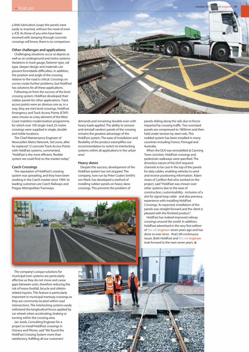
a little lubrication (soap) the panels wereeasily re-inserted, without the need of evena JCB. As those of you who have beeninvolved with tamping through concretecrossings will know, there is no comparison.
Other challenges and applicationsChallenging situations occur at depots as
well as on underground and metro systems.Variations in track gauge, fastener type, railtype, sleeper design and materials canpresent formidable difficulties. In addition,the position and angle of the crossingrelative to the road is critical. Crossings oncurves create further problems, but HoldFasthas solutions for all these applications.
Following on from the success of the levelcrossing system, HoldFast developed theirrubber panels for other applications. Trackaccess points were an obvious one as, in away, they are mini level crossings. HoldFastEmergency and Track Access Points (ETAP)were chosen as a key element of the WestCoast mainline modernisation programme,for which over 100 single-track 25-metrecrossings were supplied in single, doubleand treble locations.
The Chief Maintenance Engineer ofNewcastle’s Metro Network, Sid Lewis, afterhe replaced 12 concrete Track Access Pointswith HoldFast systems, commented,“HoldFast is the most efficient, flexiblesystem we could find on the market today.”
Czech CrossingsThe reputation of HoldFast’s crossing
system was spreading, and they have beenworking in the Czech market since 1994. Itsleading customers are Czech Railways andPrague Metropolitan Tramways.
The company’s unique solutions formunicipal tram systems are particularlyeffective as they do not move and causegaps between units, therefore reducing therisk of heavy footfall, bicycle and stiletto-related injuries. This feature is particularlyimportant in municipal tramway crossings asthey are commonly located within roadintersections. The interlocking systems easilywithstand the longitudinal forces applied bycar wheels when accelerating, braking orturning within the crossing area.
Jan Jezek, Consulting Engineer for aproject to install HoldFast crossings inOstrava and Pilsner, said “We found theHoldFast Crossing System more thansatisfactory, fulfilling all our customers’
demands and remaining durable even withheavy loads applied. The ability to removeand reinstall random panels of the crossingremains the greatest advantage of theHoldFast system. The ease of installation andflexibility of the product exemplifies ourrecommendation to switch to interlockingsystems within all applications in the urbanarea”.
Heavy skewsDespite this success, development of the
HoldFast system has not stopped. Thecompany, now run by Peter Coates-Smith’sson Mark, has developed a method ofinstalling rubber panels on heavy skewcrossings. This prevents the problem of
panels sliding along the rails due to forcesimparted by crossing traffic. Two oversizedpanels are compressed to 1800mm and thenheld under tension by steel rods. Thisrodded system has been installed in manycountries including France, Portugal andAustralia.
When the DLR was remodelled at CanningTown Junction, HoldFast crossings andpedestrian walkways were specified. Thedriverless nature of the DLR requiredchannels to be cast in the top of the panelsfor data cables, enabling vehicles to sendand receive positioning information. AdamJones of Carillion Rail who worked on theproject, said “HoldFast was chosen overother systems due to the ease ofconstruction, customisability - inclusion of aslot for signal loop cable - and also previousexperience with installing HoldFastCrossings. As expected, installation of thepanels was straight forward and the client ispleased with the finished product.”
HoldFast has indeed improved railwaycrossings around the world. In addition,HoldFast advertised in the very first editionof the rail engineer seven years ago and hasdone so ever since - that’s 84 continuousissues. Both HoldFast and the rail engineerlook forward to the next seven years.
october 2011 | the rail engineer | 31feature
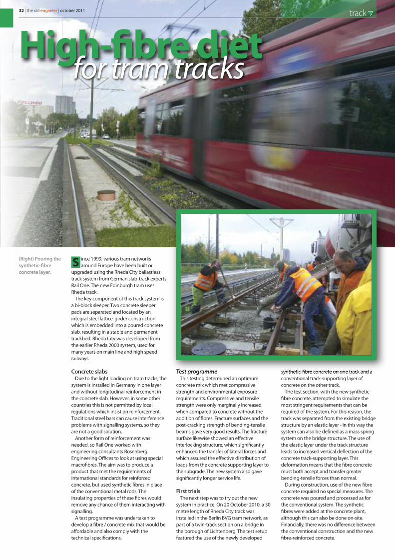
ince 1999, various tram networksaround Europe have been built or
upgraded using the Rheda City ballastlesstrack system from German slab-track expertsRail One. The new Edinburgh tram usesRheda track.
The key component of this track system isa bi-block sleeper. Two concrete sleeperpads are separated and located by anintegral steel lattice-girder constructionwhich is embedded into a poured concreteslab, resulting in a stable and permanenttrackbed. Rheda City was developed fromthe earlier Rheda 2000 system, used formany years on main line and high speedrailways.
Concrete slabsDue to the light loading on tram tracks, the
system is installed in Germany in one layerand without longitudinal reinforcement inthe concrete slab. However, in some othercountries this is not permitted by localregulations which insist on reinforcement.Traditional steel bars can cause interferenceproblems with signalling systems, so theyare not a good solution.
Another form of reinforcement wasneeded, so Rail One worked withengineering consultants RosenbergEngineering Offices to look at using specialmacrofibres. The aim was to produce aproduct that met the requirements ofinternational standards for reinforcedconcrete, but used synthetic fibres in placeof the conventional metal rods. Theinsulating properties of these fibres wouldremove any chance of them interacting withsignalling.
A test programme was undertaken todevelop a fibre / concrete mix that would beaffordable and also comply with thetechnical specifications.
Test programmeThis testing determined an optimum
concrete mix which met compressivestrength and environmental exposurerequirements. Compressive and tensilestrength were only marginally increasedwhen compared to concrete without theaddition of fibres. Fracture surfaces and thepost-cracking strength of bending-tensilebeams gave very good results. The fracturesurface likewise showed an effectiveinterlocking structure, which significantlyenhanced the transfer of lateral forces andwhich assured the effective distribution ofloads from the concrete supporting layer tothe subgrade. The new system also gavesignificantly longer service life.
First trialsThe next step was to try out the new
system in practice. On 20 October 2010, a 30metre length of Rheda City track wasinstalled in the Berlin BVG tram network, aspart of a twin-track section on a bridge inthe borough of Lichtenberg. The test setupfeatured the use of the newly developed
synthetic-fibre concrete on one track and aconventional track-supporting layer ofconcrete on the other track.
The test section, with the new synthetic-fibre concrete, attempted to simulate themost stringent requirements that can berequired of the system. For this reason, thetrack was separated from the existing bridgestructure by an elastic layer - in this way thesystem can also be defined as a mass springsystem on the bridge structure. The use ofthe elastic layer under the track structureleads to increased vertical deflection of theconcrete track-supporting layer. Thisdeformation means that the fibre concretemust both accept and transfer greaterbending-tensile forces than normal.
During construction, use of the new fibreconcrete required no special measures. Theconcrete was poured and processed as forthe conventional system. The syntheticfibres were added at the concrete plant,although this can also be done on-site.Financially, there was no difference betweenthe conventional construction and the newfibre-reinforced concrete.
S
High-fibre dietfor tram tracks
(Right) Pouring thesynthetic-fibreconcrete layer.
32 | the rail engineer | october 2011 track

Inspection resultsIn February of 2011, after several weeks of
tram operation, a detailed inspection wasmade. No cracks were discovered in thetrack with the synthetic-fibre concrete, whilelateral cracks had developed in theconventional track, distributed over theentire length of the bridge structure. Thesecracks resulted from the increase in forcesand movement brought about by the use ofthe elastic support. The test results showedthat the fibre concrete demonstratedimproved material properties overconventional concrete in the track-supporting layer.
Analysing the results of reinforcing theconcrete track-supporting layer under theRheda City track with synthetic fibresshowed several advantages. There is no steelreinforcement, so the cost of that is saved. Inaddition, track construction is quicker asthere is no need to install that reinforcementlayer and, if track is being replaced, thisreduces possession times needed.
Of course, the original requirement of thisproject is also met as the new fibre concretedoes not interfere with signalling systems.Electromagnetic compatibility is no longeran issue, even if one considers the futureintroduction of ever more complextechnology.
Substitution of longitudinal reinforcementby synthetic fibres also removes the need todivert stray current from the track.Consequently, the expensive installation ofearthing measures, and the associatedconnection cables, is no longer required.
So a project to remove signallinginterference caused by the concretetrackbed has resulted in a simpler and morecost-effective construction technique.Already, engineers at NAMA ConsultingEngineers and Planners SA have picked upon this new technology, and used it as partof the upgrade of Line 1 of the Athens Metroin Greece.
Information for this article kindly supplied byHans-Christian Rossmann - Rail One GmbH,Torsten Rosenberg - Rosenberg EngineeringOffices and Wulf Heineking-Fürstenau -Berlin Public Transport Authority (BVG)
october 2011 | the rail engineer | 33track
(Right) Pre-assembled track panels. (Below) Finished track construction.(Inset) Synthetic-fibre concrete.
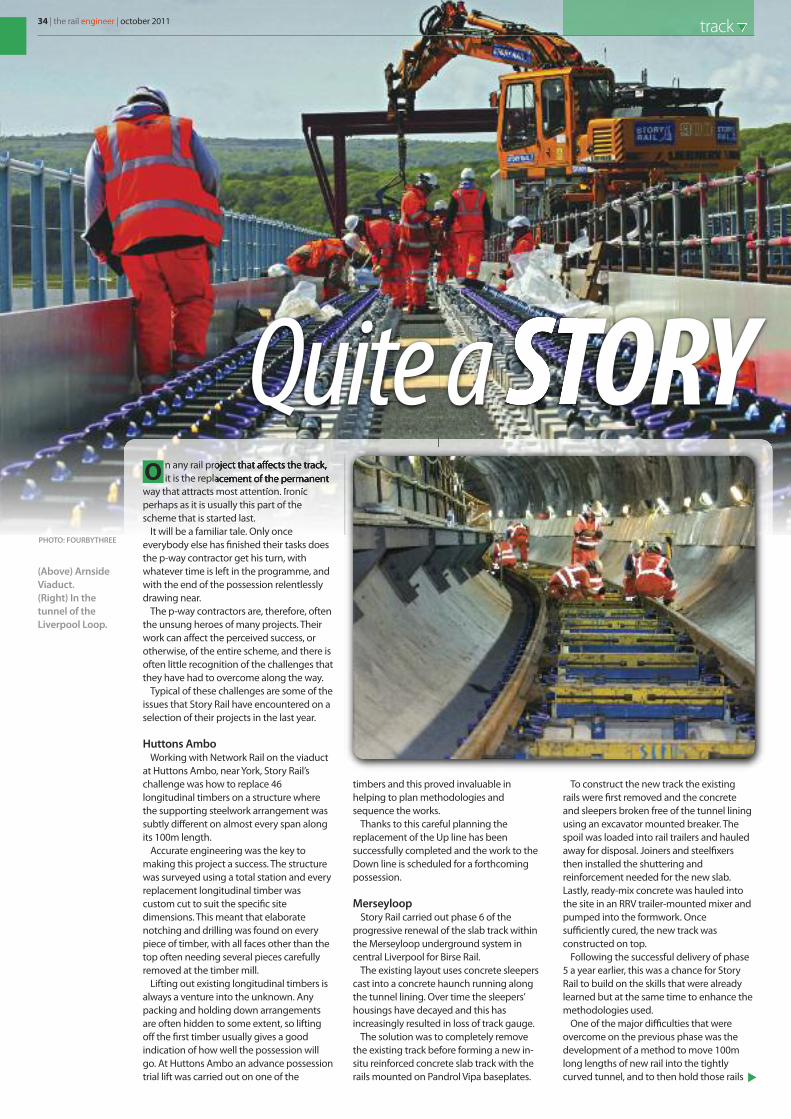
34 | the rail engineer | october 2011 track
n any rail project that affects the track,it is the replacement of the permanent
way that attracts most attention. Ironicperhaps as it is usually this part of thescheme that is started last.
It will be a familiar tale. Only onceeverybody else has finished their tasks doesthe p-way contractor get his turn, withwhatever time is left in the programme, andwith the end of the possession relentlesslydrawing near.
The p-way contractors are, therefore, oftenthe unsung heroes of many projects. Theirwork can affect the perceived success, orotherwise, of the entire scheme, and there isoften little recognition of the challenges thatthey have had to overcome along the way.
Typical of these challenges are some of theissues that Story Rail have encountered on aselection of their projects in the last year.
Huttons AmboWorking with Network Rail on the viaduct
at Huttons Ambo, near York, Story Rail’schallenge was how to replace 46longitudinal timbers on a structure wherethe supporting steelwork arrangement wassubtly different on almost every span alongits 100m length.
Accurate engineering was the key tomaking this project a success. The structurewas surveyed using a total station and everyreplacement longitudinal timber wascustom cut to suit the specific sitedimensions. This meant that elaboratenotching and drilling was found on everypiece of timber, with all faces other than thetop often needing several pieces carefullyremoved at the timber mill.
Lifting out existing longitudinal timbers isalways a venture into the unknown. Anypacking and holding down arrangementsare often hidden to some extent, so liftingoff the first timber usually gives a goodindication of how well the possession willgo. At Huttons Ambo an advance possessiontrial lift was carried out on one of the
timbers and this proved invaluable inhelping to plan methodologies andsequence the works.
Thanks to this careful planning thereplacement of the Up line has beensuccessfully completed and the work to theDown line is scheduled for a forthcomingpossession.
MerseyloopStory Rail carried out phase 6 of the
progressive renewal of the slab track withinthe Merseyloop underground system incentral Liverpool for Birse Rail.
The existing layout uses concrete sleeperscast into a concrete haunch running alongthe tunnel lining. Over time the sleepers’housings have decayed and this hasincreasingly resulted in loss of track gauge.
The solution was to completely removethe existing track before forming a new in-situ reinforced concrete slab track with therails mounted on Pandrol Vipa baseplates.
To construct the new track the existingrails were first removed and the concreteand sleepers broken free of the tunnel liningusing an excavator mounted breaker. Thespoil was loaded into rail trailers and hauledaway for disposal. Joiners and steelfixersthen installed the shuttering andreinforcement needed for the new slab.Lastly, ready-mix concrete was hauled intothe site in an RRV trailer-mounted mixer andpumped into the formwork. Oncesufficiently cured, the new track wasconstructed on top.
Following the successful delivery of phase5 a year earlier, this was a chance for StoryRail to build on the skills that were alreadylearned but at the same time to enhance themethodologies used.
One of the major difficulties that wereovercome on the previous phase was thedevelopment of a method to move 100mlong lengths of new rail into the tightlycurved tunnel, and to then hold those rails
O
STORYQuite a(Above) ArnsideViaduct.(Right) In thetunnel of theLiverpool Loop.
PHOTO: FOURBYTHREE

!"!#$%%%&"#'()(*!+&,'&-.$#'$/01$'-#$2'(3$'($,'0#*,#$#43$5#'()$6*!+$#3*2$*#75#'()$6*!+8$9-(:4$6'*1$;01-"#(!*+$<"#*#38$=*(+!"+38$=-2>(!*8$=?@$AB?#3+7$CD@@E$FGCEEC$$H$$I*J7$CD@@E$FGCEED$$H$$32*!+7$(*!+K"#'():('-L&,'&-.
M-*+!#)$$N$$O3*2%'(.$$N$$P3+!Q3()
%%%&"#'():('-L&,'&-.%%%&"#'():('-L&,'&-.
=R;<BO7$S*)$T-(03)RU=?O;UB7$?(0"!13$ !*1-,#8$=-2>(!*
V6UW<=O7$ !"#$%$"&'"('%)*+$,-$%.')-,&.'."',%%$%.'./*'!*0"#,-',&1'$&%.,--,.$"&'"('./*'"-1',&1'&*2'3!$14*'%*+.$"&%5'6/$%')!"7*+.'$&+-81*1'./*'!*0"#,-',&1'!*$&%.,.*0*&.'"('./*'.!,+9&
V4'#':(*L4$>)$W'3$6!+3)
''''''''':."!;'<!"8)''=''>8!4/'?",1'@&18%.!$,-'A%.,.*''=''B,!-$%-*'''=''B803!$,'''='''BCD'EFC'''='''6*-G'HIDDJ'KLHJJH
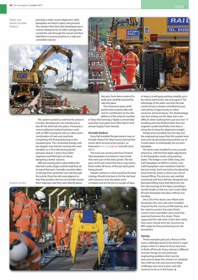
36 | the rail engineer | october 2011 track
precisely in their correct alignment whilebaseplates are fixed in place and grouted.The solution that Story Rail developed was acustom-designed set of rollers and jigs thatcarried the rails through the tunnel and thenheld them in precise position in a safe andcontrolled manner.
The system worked so well that for phase 6a further development was introduced toalso lift the third rails into place. Previously amore traditional method had been used,with an RRV moving the rails on rollers and acombination of men and machinescompleting the final positioning on theinsulated pots. This contrasted sharply withthe elegant way that the running rails werehandled, so in the intervening periodbetween phases 5 and 6 Story Rail’sengineers and fabricator set aboutdesigning a better solution.
With the running rails in place before thethird rail a series of jigs could be built that saton top of the track. Centrally mounted rollerson the jigs then carried the new rails throughthe tunnel. Once the rails were adjacent totheir final position, the turn of a handle movedthem sideways until they were directly above
the pots. From here a series of in-built jacks carefully lowered therails into place.
This impressive piece of kitperformed exceptionally welland its contribution to the safedelivery of the scheme resulted
in Story Rail winning a Highly Commendedaward for Innovation from Birse Rail in theirannual Supply Chain Awards.
Arnside ViaductStory Rail installed the permanent way on
Arnside Viaduct for May Gurney during theirrecent deck reconstruction project, asfeatured in the rail engineer issue 80 (June2011).
The track was constructed from PandrolVipa baseplates mounted on steel stoolsthat were part of the deck panels. The fastpace of the job meant that the p-way had tofinish within 48 hours of the last deck panelbeing placed.
Debate centred on what would be the beststrategy. Would it be best to hit the site hardwith resources once the decks werecomplete and do the lot in a couple of days,
or keep a small gang working steadily just afew decks behind the rate of progress? Theadvantage of the latter was that the taskwould remain a steady controlled processwith plenty of opportunity to refineresources and techniques. The disadvantagewas that setting out the Vipas was moredifficult when working from just one end - ifinstalling onto the finished deck then theengineer would need little more than astring line to keep the alignment straight.
Steady and controlled won the day andthe engineering issues that this created wereovercome by good planning and the use ofa total station to individually set out eachbaseplate.
The decks were installed to very accuratetolerances, with the final slight adjustmentto the baseplates made using packingplates. The bridge is over 500m long, andwith baseplates at 600mm centres, over3,000 baseplates were needed in total forthe two tracks. Each one had to be placed byhand onto the stools so there was a lot ofmanual lifting. This process was carefullymonitored and Story Rail also designed andfabricated lifting tools that fitted into thefast clip housings of the Vipas, providing asturdy handle so that two men could safelylift each baseplate into place without anybending.
Once all of the decks were fitted withbaseplates the new rails were installed.Inspired by the success at Merseyloop, andthe need to protect the paint finish,custom built assemblies were used thatspanned between the stools. Thesesupported the rails clear of the deck whilethey were moved onto the structure byRRV ready for final positioning into thebaseplates.
VarietyThese examples give just a flavour of the
many challenges faced at the end of a majorproject when it is down to the p-way teamto finish off the job. Every scheme is differentand each brings its own particularengineering problems that must beovercome to keep the contract on schedule.Story Rail has met and overcome thosechallenges over recent years, and willcontinue to do so in the future.
(Right andbelow).ArnsideViaduct.
Huttons Ambo.

We’ll keep you on the right track.
One sure fi re way to keep your business on the right track is to partner with the best. WVCO Railroad Division is the industry leader in innovative products and application systems for wood and concrete sleeper remediation.
Our products are the trusted solution for major railways all over North America (Burlington Northern Sante Fe, Canadian National, Canadian Pacifi c, CSXT and Norfolk Southern), the United Kingdom, with distribution by Hallrail (Tube Lines and Metronet on The London Underground Network and The Tyne & Wear Metro), and in Europe (Infrabel, Belgium).
We’ll keep your railway on the right track.
Call Hallrail today: +44 (0) 191 526 2114 • hallrail.co.uk
For more information about WVCO Railroad, visit: wvcorailroad.comWVWVWVWVWVWVWVWVCOCOCCOCOCOCOCO R RR R R R RRaiaiaiaiiaiiia lrlrlrlrlrlrllroaoaoaoaoaoaooaaaadddddd,d,dddd vvv vv v vvisisiisisisisssitiiitititit: : : :: wvwvwvwvwvvcocococooc rararaaaaararr ililililillililiilllrororororooroororooadadadadaadaa .c.c.c.cccomomomomomomom
HALLRAILE S T A B L I S H E D 1 9 4 8

38 | the rail engineer | october 2011 track
lat spots onwheels cause
problems for all railway operators. They areparticularly prevalent during the autumn‘slip-slide’ period when fallen leaves on railsbecome crushed, causing wheels to lockduring braking.
It is not just a British problem. MTA Metro-North Railroad (MNR), based in New York,operates a total of 1,050 carriages over 170route miles each day, which equates to 8,400wheels travelling a total of almost 1.5 millionmiles daily. There is therefore a highprobability of wheel flats developing duringoperation.
Damage and failureDamaged wheels are
known to damage trackand vehicle bogies, givepoor ride quality withincreased noise andincrease the risk ofderailments. The need tocarry out unplanned
repairs also reducesfleet availability,
creates unmanageable peak loads in depotsand decreases vehicle availability.
In January 2009, an axle fractureoccurred on a Shoreliner coach. Theincident led to only a minor servicedisruption, but analysis of the fractureindicated that it was caused by higher thannormal cyclic stresses which developed inthe axle due to the presence of a severeflat in the tread of the wheel. It is estimatedthat the life of the axle under thesecircumstances could only be 3 to 8 days.
With these risks there is a clear need toidentify and classify wheel flats quickly andconsistently. Wheels with a significant flatmust be removed from service immediately,while wheels with only minor damage canbe scheduled for correction. This schedulinghas to take account of the availability of cars
for service as well
as the practicalcapacity of wheellathe facilities.
Effective wheelset inspection can beproblematic. Variable lighting and workingconditions, and difficulties in observing theentire tread surface, mean that it is difficultto quantify the magnitude of defects found.Clearly the need to inspect a large numberof wheels, corresponding to over 13 miles oftread surface daily, is a very significantundertaking.
Wheelset costsDamaged wheels are also expensive. With
each wheelset priced at about $6,000 thevalue for the entire fleet of vehicles (4,200wheelsets) is: 4,200 x $6K = $25.2 Million.
This equates to an annual replacementcost of $10M, based on an average wheel lifeof 2.5 years.
Effective wheel maintenance can increaseservice life to 3 years, giving annual savingsat MNR of $1.6 Million, or $16 Million over 10years. This is in addition to the benefits from
reduced damage to track, andvehicle bogies.
Wheel Impact Load Detection Because of the magnitude of the
inspection requirement, and theneed to manage wheel conditions atsuch a level, MNR decided toimplement an automatic WheelImpact Load Detection (WILD) system.Based on DeltaRail’s WheelChextechnology, WILD is in service on allfour tracks at the entrance to the ParkAvenue tunnel. All trains leaving themain line for Grand Central terminalpass over the measurement site, anaverage of 600 trains every day.
F
MW I L D
N Rgoes
John Kesich, AdrianGolbyw r i t e r s
Shoreliner train.
(Above)A detached wheel,rusty from havingfallen into theHudson River.(Right) A significantwheel flat.
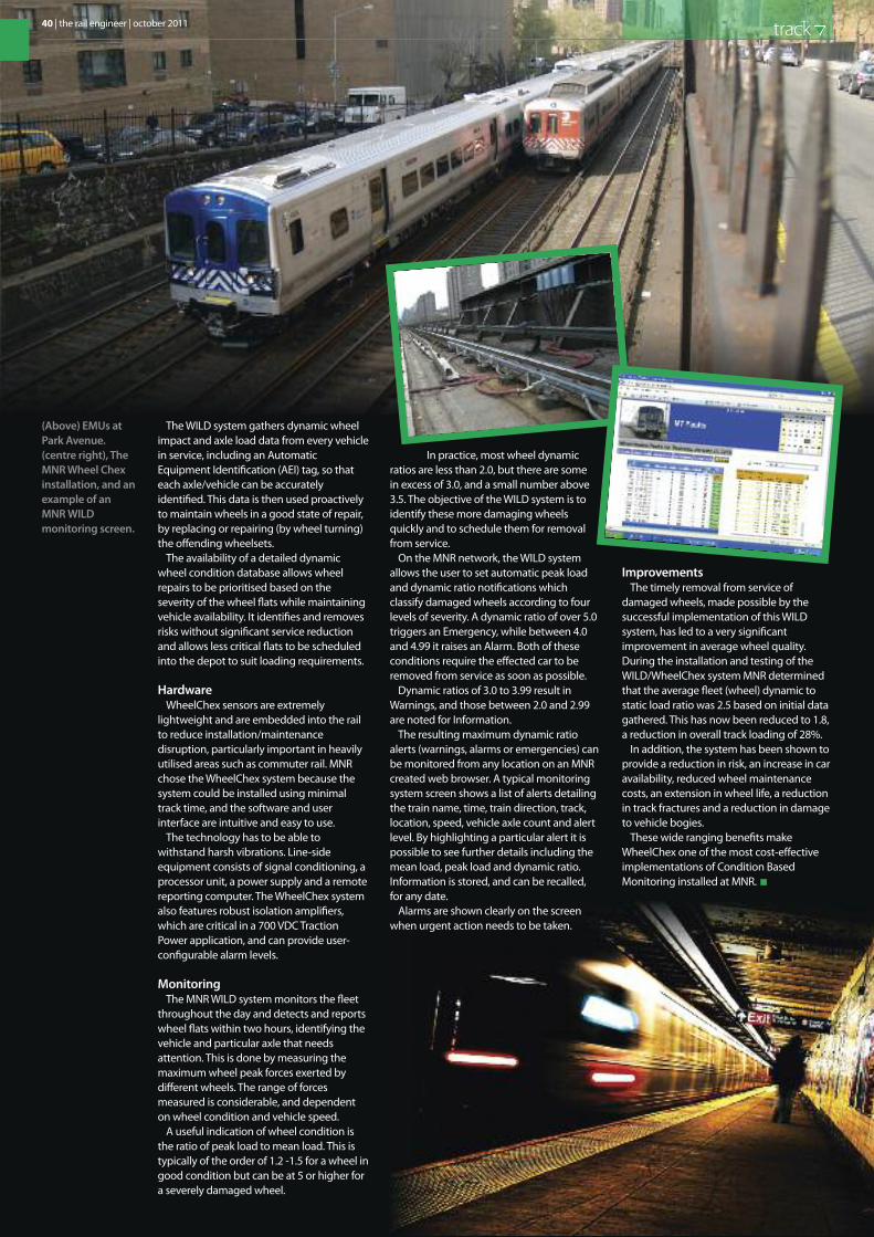
40 | the rail engineer | october 2011 track
The WILD system gathers dynamic wheelimpact and axle load data from every vehiclein service, including an AutomaticEquipment Identification (AEI) tag, so thateach axle/vehicle can be accuratelyidentified. This data is then used proactivelyto maintain wheels in a good state of repair,by replacing or repairing (by wheel turning)the offending wheelsets.
The availability of a detailed dynamicwheel condition database allows wheelrepairs to be prioritised based on theseverity of the wheel flats while maintainingvehicle availability. It identifies and removesrisks without significant service reductionand allows less critical flats to be scheduledinto the depot to suit loading requirements.
HardwareWheelChex sensors are extremely
lightweight and are embedded into the railto reduce installation/maintenancedisruption, particularly important in heavilyutilised areas such as commuter rail. MNRchose the WheelChex system because thesystem could be installed using minimaltrack time, and the software and userinterface are intuitive and easy to use.
The technology has to be able towithstand harsh vibrations. Line-sideequipment consists of signal conditioning, aprocessor unit, a power supply and a remotereporting computer. The WheelChex systemalso features robust isolation amplifiers,which are critical in a 700 VDC TractionPower application, and can provide user-configurable alarm levels.
MonitoringThe MNR WILD system monitors the fleet
throughout the day and detects and reportswheel flats within two hours, identifying thevehicle and particular axle that needsattention. This is done by measuring themaximum wheel peak forces exerted bydifferent wheels. The range of forcesmeasured is considerable, and dependenton wheel condition and vehicle speed.
A useful indication of wheel condition isthe ratio of peak load to mean load. This istypically of the order of 1.2 -1.5 for a wheel ingood condition but can be at 5 or higher fora severely damaged wheel.
In practice, most wheel dynamicratios are less than 2.0, but there are somein excess of 3.0, and a small number above3.5. The objective of the WILD system is toidentify these more damaging wheelsquickly and to schedule them for removalfrom service.
On the MNR network, the WILD systemallows the user to set automatic peak loadand dynamic ratio notifications whichclassify damaged wheels according to fourlevels of severity. A dynamic ratio of over 5.0triggers an Emergency, while between 4.0and 4.99 it raises an Alarm. Both of theseconditions require the effected car to beremoved from service as soon as possible.
Dynamic ratios of 3.0 to 3.99 result inWarnings, and those between 2.0 and 2.99are noted for Information.
The resulting maximum dynamic ratioalerts (warnings, alarms or emergencies) canbe monitored from any location on an MNRcreated web browser. A typical monitoringsystem screen shows a list of alerts detailingthe train name, time, train direction, track,location, speed, vehicle axle count and alertlevel. By highlighting a particular alert it ispossible to see further details including themean load, peak load and dynamic ratio.Information is stored, and can be recalled,for any date.
Alarms are shown clearly on the screenwhen urgent action needs to be taken.
ImprovementsThe timely removal from service of
damaged wheels, made possible by thesuccessful implementation of this WILDsystem, has led to a very significantimprovement in average wheel quality.During the installation and testing of theWILD/WheelChex system MNR determinedthat the average fleet (wheel) dynamic tostatic load ratio was 2.5 based on initial datagathered. This has now been reduced to 1.8,a reduction in overall track loading of 28%.
In addition, the system has been shown toprovide a reduction in risk, an increase in caravailability, reduced wheel maintenancecosts, an extension in wheel life, a reductionin track fractures and a reduction in damageto vehicle bogies.
These wide ranging benefits makeWheelChex one of the most cost-effectiveimplementations of Condition BasedMonitoring installed at MNR.
(Above) EMUs atPark Avenue.(centre right), TheMNR Wheel Chexinstallation, and anexample of anMNR WILDmonitoring screen.


42 | the rail engineer | october 2011 track
A new tool
he rail industry is increasingly beingchallenged to improve the
management and extend the life of one ofits basic and most expensive assets, the railsthemselves. This challenge is being met by abetter understanding of rail metallurgy,lubrication, profiles and direct interventionthrough material removal. Of these, thelatter has seen the development of the railgrinding machine from the earliest days ofconverted trams to modern, purpose-builttrains.
Rail managementThe benefits of rail management through
rail grinding have long been recognised inthe worldwide rail industry. In the UK, aseconomics, regulatory and safety issueshave come more to the forefront over recentyears, the technology has seen a steadyincrease in application.
Grinding, though, has its limitations, risksand environmental issues. It cannot be usedin some tunnels or high fire risk areas, it hastrouble dealing effectively with heavy raildamage, and much of its waste productremains on the track. So, after some 100years of rail grinding, it is time to find a newtool in the toolbox.
The rail miller offers a moreenvironmentally-effective method of railmanagement with an ability to do in onepass something that a rail grinder cannot doin many, if at all. Most importantly, for manymodern signalling and traction systems,milling does not leave its waste productbehind on the track. Instead, it is recoveredback inside the machine so it can bedisposed of safely
An accepted technologyRail milling has been covered in the rail
engineer before, most recently in issue 69(July 2010). The technology has becomeaccepted in Europe and the Far East, withinvestment in machines both by railoperators and contractors.
STRABAG Rail is at the forefront of this newtechnology and has invested heavily in it. Amajor service supplier to rail organisationsaround Europe, the company has a wideranging fleet of rail maintenance machinesto which it is now adding four rail millingmachines, two rail-road and two track-basedunits, for a total investment of more than€100 million. It has even had one of the rail-road machines specially converted for useon the British loading gauge.
STRABAG Rail brought that unit overduring 2010 and, having passed therequirements for operation on theDocklands Light Railway, it undertooksome trial work which saw it completesome 9600 metres during six shifts oftrouble-free track milling, producing 4100metres of finished track allowing for areasof severe damage which required two orthree passes. Various representatives ofNetwork Rail and London Undergroundsaw the rail miller in operation, and werekeen to try it on their own networks assoon as was practical. A return visit hasbeen arranged for late in 2011.
ConsistencyOne key advantage of the rail miller is that
the finished rail profile is built into thecutting head. This is manufactured withrenewable cutter teeth so that there is nopossibility of inconsistency in the profilefinish. While the milling leaves small facets,around the size of a thumbnail, on the railhead these are easily removed by atangential grinding wheel positioned justbehind the milling head which leaves afinished roughness of 3-4µmm. This isperfect for visual, ultrasonic or measurementinspection to ensure that defects have beenremoved, and that the desired profile hasbeen achieved.
Environmental advantagesThe design of the milling head unit and
the patented grinding finish systemensures that both the swarf generated inmilling and dust from the grinding are99% recovered by a process that aconventional rail grinder cannot match. Sothere is little or no residual waste left onthe track to contaminate rolling stock andthe track bed, especially significant forpoints equipment and track circuits.Recovered swarf can be recycled whilstthe dust may be disposed of in acontrolled manner.
T
René Feulerw r i t e r
in the box
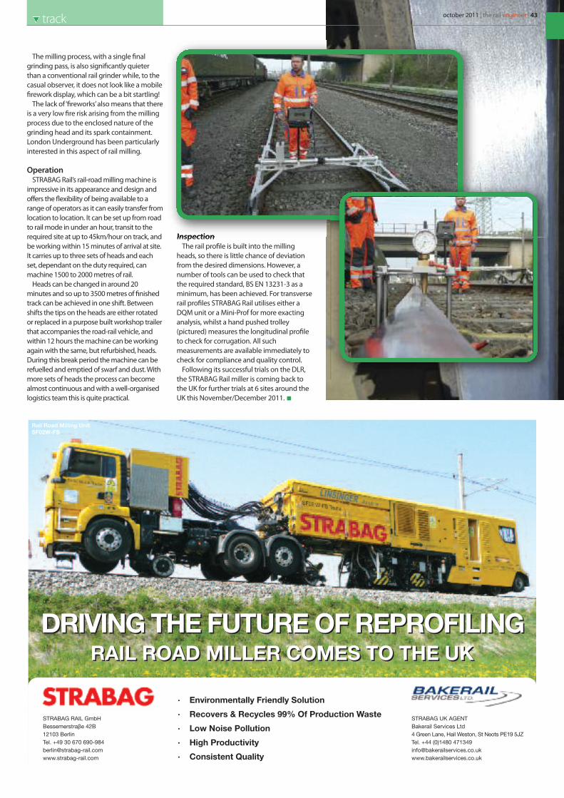
The milling process, with a single finalgrinding pass, is also significantly quieterthan a conventional rail grinder while, to thecasual observer, it does not look like a mobilefirework display, which can be a bit startling!
The lack of ‘fireworks’ also means that thereis a very low fire risk arising from the millingprocess due to the enclosed nature of thegrinding head and its spark containment.London Underground has been particularlyinterested in this aspect of rail milling.
OperationSTRABAG Rail’s rail-road milling machine is
impressive in its appearance and design andoffers the flexibility of being available to arange of operators as it can easily transfer fromlocation to location. It can be set up from roadto rail mode in under an hour, transit to therequired site at up to 45km/hour on track, andbe working within 15 minutes of arrival at site.It carries up to three sets of heads and eachset, dependant on the duty required, canmachine 1500 to 2000 metres of rail.
Heads can be changed in around 20minutes and so up to 3500 metres of finishedtrack can be achieved in one shift. Betweenshifts the tips on the heads are either rotatedor replaced in a purpose built workshop trailerthat accompanies the road-rail vehicle, andwithin 12 hours the machine can be workingagain with the same, but refurbished, heads.During this break period the machine can berefuelled and emptied of swarf and dust. Withmore sets of heads the process can becomealmost continuous and with a well-organisedlogistics team this is quite practical.
InspectionThe rail profile is built into the milling
heads, so there is little chance of deviationfrom the desired dimensions. However, anumber of tools can be used to check thatthe required standard, BS EN 13231-3 as aminimum, has been achieved. For transverserail profiles STRABAG Rail utilises either aDQM unit or a Mini-Prof for more exactinganalysis, whilst a hand pushed trolley(pictured) measures the longitudinal profileto check for corrugation. All suchmeasurements are available immediately tocheck for compliance and quality control.
Following its successful trials on the DLR,the STRABAG Rail miller is coming back tothe UK for further trials at 6 sites around theUK this November/December 2011.
october 2011 | the rail engineer | 43track
DRIVING THE FUTURE OF REPROFILINGDRIVING THE FUTURE OF REPROFILINGRAIL ROAD MILLER COMES TO THE UKRAIL ROAD MILLER COMES TO THE UK
STRABAG RAIL GmbH
Bessemerstra e 42B
12103 Berlin
Tel. +49 30 670 690-984
www.strabag-rail.com
β
· Environmentally Friendly Solution
· Recovers & Recycles 99% Of Production Waste
· Low Noise Pollution
· High Productivity
· Consistent Quality
STRABAG UK AGENT
Bakerail Services Ltd
4 Green Lane, Hail Weston, St Neots PE19 5JZ
Tel. +44 (0)1480 471349
www.bakerailservices.co.uk
Rail Road Milling Unit
SF02W-FS

n 8 August 2011, TransportMinister Norman Baker, on the
BBC “You and Yours” programme, askedwhy roads have to be excavated,utilities diverted and cities disrupted toinstall tramway tracks, when the year-old tracks in Princes Street Edinburghhad failed before a single tram hadturned a wheel, the damage havingbeing caused by buses and lorriesrunning over them. He went on topropose that shallow depth tracksshould be considered to reduce costsby requiring only 4% of the excavationneeded for other track types.
One solution is the LR55 track,developed to withstand heavy busesand lorries, which requires a minimumof excavation and allows utilities to beundisturbed. A modern urban road -which can carry buses and lorries for its30-year life - offers a strong foundationfor LR55 rails to be fitted into its top.The rails are supported on LR55foundation beams, 180mm high and360mm wide, each set into a trench200mm deep and 400mm wide that
does not expose the road base course.LR55 beams are stiff and strong,distributing load over a large area at apressure less than that from the heel ofa shoe.
Foundation beamsACO Technologies plc and Tram
Power Ltd have developed a robustand durable LR55 foundation beammade from polymer concrete. Thesenew beams have integral service ductsfor tramway telecommunications andpower cables, and spare ducts areavailable for utilities needing extracapacity. Such service ducts are alsoprotected from accidental excavationand damage. The ACO polymerconcrete beams are frost-resistant andself-supporting for up to 1m acrosstrenches. Each beam has a uniqueCone-Lok connector that providesaccurate beam alignment and awaterproof duct sealing.
The correct carriageway profile fortramway tracks allows two LR55 tracksto be laid at more than 100m per week.If the road profile is substandard, then anormal road contract to plane orresurface is a quick and economical firststage. Each LR55 rail can be laidseparately and the road kept open fortraffic, or at least with frontage access,by suitable traffic management. With
its small trenches, LR55 needs less than3% of the volume of excavationrequired by other track systems, whichsaves time and money and avoids theneed to remove large quantities ofhazardous road materials. This in turncuts CO2 emissions and trafficdisruption - two valuable benefits notcurrently in the costs of projects.
RailsLR55 rails, which are ‘glued’ into the
foundation beams and electricallyinsulated, also reduce noise andvibration, and no other measures areneeded to control stray currents. Inaddition, the road surface is kind toother vehicles and offers a high skidresistance. These claims are based onover 15 years of service in the Sheffieldtramway where LR55 replaced girderrails that had failed from HGV trafficafter less than a year. So far, nomaintenance has been needed and,judging by the wear, the rails shouldlast at least another 15 years. Adjacentgirder rails have corrugated but notthe LR55.
Each rail is in a separate foundationbeam, so under-street utilities remainaccessible. Routine maintenance andrepairs can be undertaken with apossession-type
O
LR55 tracksbetter for less
44 | the rail engineer | october 2011 trackReproduced copy of the rail engineer magazine issue 83 October 2011
arrangement that diverts traffic butallows trams to run. For a catastrophic(once in 40 years) failure (e.g. a break ingas mains), trams would have to stoprunning but repair is much easier withLR55. For long-term utility works,temporary crossovers can be used toallow one track to be taken out ofservice, the other being used for two-way working. This is safe, with adrive-on-sight regime and typical six-minute headways.
Voest Alpine and two steel mills inChina currently offer LR55 rails and it isunderstood that new Chinese systemsare using LR55 rails. They are alsoplanned for new tramways in Prestonand Galway. Transition rails are used inSheffield which can connect LR55 to allrail profiles so that existing networkscan be extended more economically.Switches and crossings, for turnoutsand crossovers, are based on a 25mradius, using either ‘Tadpole’ or flexibleblades. Plain LR55 rail has been bent to15m radius.
The LR55 foundation beams forcurved track are made from shorttangents, with chamfered ends, theCone-Loks giving rigid and accuratealignment. On curves tighter than 50mradius, rails are supplied already curvedand bonded into the beams, as forstraight tracks. In both cases, therequired alignment is achieved in twosteps. The LR55 beams are laid to±5mm, and the rails to ±1mm, makingit easier to get it right quickly and firsttime.
TestingA comprehensive testing
programme included 80-tonne axleloadings, so that LR55 can be used formain-line trains with 25-tonne axles.The new EU Directive on rail tunnelsafety requires new tunnels to haveflat floors to make emergencies easierto deal with, including access for roadvehicles and the safer evacuation ofpassengers: LR55 tracks provide a flattunnel floor as standard. Using LR55for Crossrail could reduce theexcavation spoil volume by over250,000 tonnes or even allow double-decker trains to run.
For existing rail tunnels, retrofittingwith LR55 provides a second benefit ofincreasing the loading gauge (DKE)without having to undermine theinvert. This allows easier electrificationand the carriage of 10ft. 6in. highcontainers: it may even allow double-decker coaches. For tube tunnels, tallerand wider - i.e. larger capacity - trainsare possible. Flat tunnel floors speedup and reduce the cost of routinemaintenance, since road vehicles,including adapted milk floats, may beused.
With the support of Burdens and ACOTechnologies plc, LR55 tracks offerfaster and more economic tramways,with much less city disruption. Tracksare quieter and need less maintenancewith a longer service life. For railways,LR55 offers economic DKEenlargement and flat tunnel floorssatisfy the new EU Directive.
w www.LR55-rail-road-system.co.uk
GOGREENOur Lighting Towers may look Grey...But they’re actually very Green
• Lower fuel consumption• Lowest sound power levels• Economical to transport
Phone us on 0845 409 0272 or email [email protected]
Network RailApproved
RESERVE YOUR SMC LIGHTING TOWERSTODAY...DON’T GET CAUGHT IN THE DARK!
For every SMC Lighting Tower ordered this year, we will donate £10 to the LIGHTHOUSE CLUB Construction Industry Charity.
october 2011 | the rail engineer | 45trackReproduced copy of the rail engineer magazine issue 83 October 2011
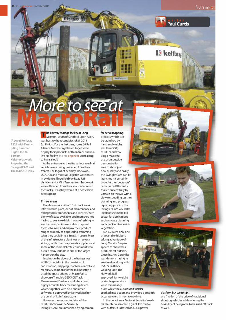
46 | the rail engineer | october 2011 feature
Paul Curtisw r i t e r
he Railway Storage facility at LongMarston, south of Stratford upon Avon,
was host to the recent MacroRail 2011Exhibition. For the first time, some 60 RailAlliance Members gathered together todisplay their products both on track and in alive rail facility. the rail engineer went alongto have a look.
At the entrance to the site, various road-railvehicles were being unloaded from theirtrailers. The logos of Keltbray, Trackwork,UCA, JCB and Motorail Logistics were muchin evidence. Three Keltbray Road RailVehicles and a Mini Tamper from Trackworkwere offloaded from their low loaders ontothe track just as they would at a possessionaccess point.
Three areasThe show was split into 3 distinct areas;
infrastructure plant, depot maintenance androlling stock components and services. Withplenty of space available, and members nothaving to pay to exhibit, it was refreshing tosee that companies were able to spreadthemselves out and display their productranges properly as opposed to crammingwhat they could into a 3m x 3m space. Mostof the infrastructure plant was on severalsidings, while the components suppliers andsome of the more delicate equipment weretucked away indoors in one of the largerhangers on the site.
Just inside the doors of the hanger wasKOREC, specialist in the provision ofconstruction, mapping, machine control andrail survey solutions for the rail industry. Itused the space offered at MacroRail toshowcase Trimble’s GEDO CE TrackMeasurement Device, a multi-function,highly accurate track measuring devicewhich, together with field and officesoftware, is approved by Network Rail foruse on all of its infrastructure.
However the undoubted star of theKOREC show was the SenseFlySwingletCAM, an unmanned flying camera
for aerial mappingprojects which canbe launched byhand and weighsless than 500g.KOREC’s AndrewBlogg made fulluse of an outsidedemonstrationarea to show justhow quickly and easilythe SwingletCAM can belaunched - it certainlybrought the spectators’cameras out! Recentlytrialled successfully byCostain on the M1 with aview to speeding up theirplanning and progressreporting process, theSwinglet CAM would beideal for use in the railsector for applicationssuch as route planningand checking track-sidevegetation.
KOREC were only oneof several exhibitorstaking advantage ofLong Marston’s openspaces to show theirproducts off outside.Close by, Arc-Gen Hiltawas demonstrating itsWeldmaker along withESAB’s Railtrackwelding unit. TheNetwork Railapproved lightweightportable generatorswere remarkablyquiet while the automated weldersparked into action and provided a smoothaccurate weld in next to no time.
In the depot area, Motorail Logistics’ road-rail shunter resembled a giant JCB tractorwith buffers. It is based on a JCB power
platform but weighs inat a fraction of the price of traditionalshunting vehicles while offering theflexibility of being able to be used off trackas well.
T
MacroRailMore to see at
(Above) KeltbrayP228 with Fambopiling hammer.(Right, top tobottom)Keltbray at work,Preparing theSwingletCAM andThe Inside Display.

Inside the hallBack in the hanger, Sheffield-based
Zonegreen had brought along a brand-newautomated remote control system whichallows maintenance depots and sidings tooperate manual points from the vehiclewithout having to leave the cab.
Also of interest to depot operators wasAutodrain, which was exhibiting an oildrainage pump that is currently installed atthe Hitachi Depot in Ashford, Kent. Thecompany also designs and manufactures aproduct called Oil Away. This pumps hot oilstraight from the engine sump into a storagetank. Leak-free twist connections to thesump mean fewer oil spills in the workshopsand prevent any burns from hot oil tomaintenance operatives.
Bratts Ladders of Nottingham wasdemonstrating various access platforms and
ladders which were made out of glass fibrewhich are already being used in depots andheritage maintenance yards for accessingrolling stock safely. Visitors watched as Bratts’personnel erected a lightweight Teletowerto a height of 4 meters in a few minutes.Even more impressively, they dismantled itagain, folded it up, and fitted it into the backof an estate car.
Achilles showcased Link-up, the rail industrysupplier registration and qualification scheme,which is used extensively by procurement,engineering, safety and quality professionals.Approximately 2,700 individual users currentlyhave access to Link-up information on existingand potential suppliers to aid them with theirprocurement activities.
Back outsideOutside again, and Trackwork were
demonstrating their mini-tamper on a 200metre run of siding. This road-rail Plasser &Theurer 08 Tamper, which at only 7 metreslong, can turn itself round on its own axis.After a 200 metre run it simply jacked itselfup, spun around through 180 degrees, andproceeded to carry out another run.
Keltbray’s three road-railers, which hadearlier been seen at the entrance, were upnow also in the sidings. A tracked KomatsuP228, fitted with a Movax SP50-W vibratorypiling hammer, was demonstrating pickingup tubular steel pile then starting to driveit into the ground. A second P228, this onewith a Fambo piling hammer, finished the
october 2011 | the rail engineer | 47
C
M
Y
CM
MY
CY
CMY
K
IG_QtrPageBSAd_AW.pdf 25/7/11 13:00:49
As specialists in the provision of the construction,
mapping, machine control and rail survey solutions
for the Rail Industry, the KOREC team will be on
hand throughout the event answering questions on
the complete KOREC rail portfolio.
Visit us at The Infrastructure Show (Road & Rail Hub
RA06) to � nd out more about our range of modern
solutions for the rail industry, including the FARO
Focus 3D Scanner and the SenseFly Swinglet CAM.
DID YOU MISS US
AT MacroRail?Come and see us at The Infrastructure Show to
discuss your next rail project.
www.korecgroup.com
tel: 0845 603 1214
KOREC-11-020 Infrastructure Show Ad.indd 1 22/09/2011 15:51
More to see at
feature
ESAB demonstratingrail welding.
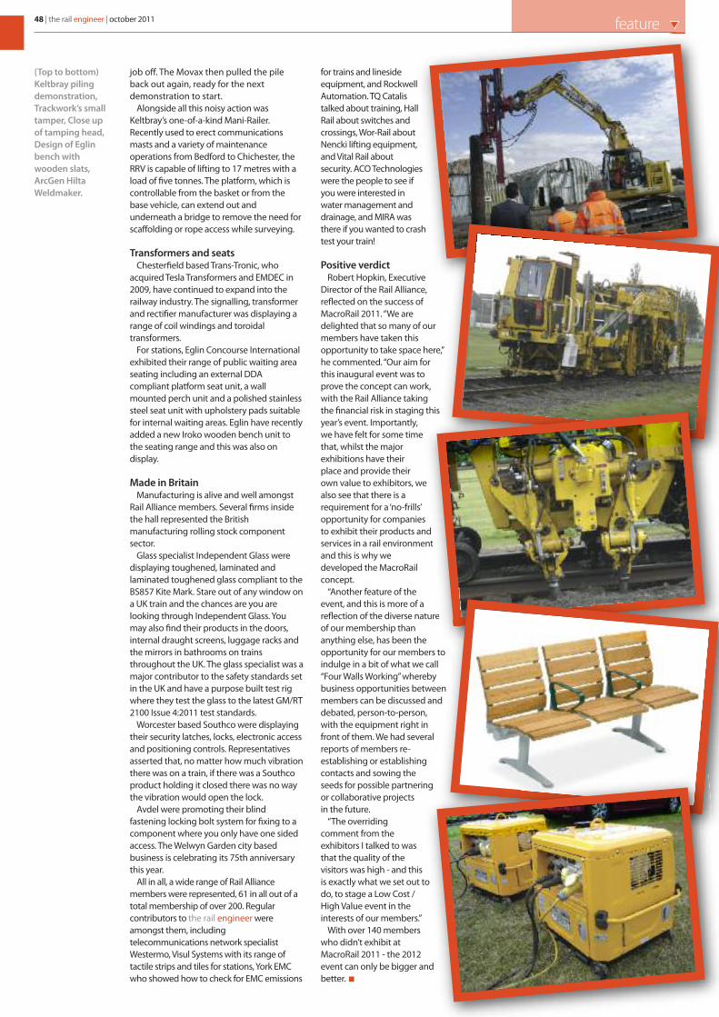
job off. The Movax then pulled the pileback out again, ready for the nextdemonstration to start.
Alongside all this noisy action wasKeltbray’s one-of-a-kind Mani-Railer.Recently used to erect communicationsmasts and a variety of maintenanceoperations from Bedford to Chichester, theRRV is capable of lifting to 17 metres with aload of five tonnes. The platform, which iscontrollable from the basket or from thebase vehicle, can extend out andunderneath a bridge to remove the need forscaffolding or rope access while surveying.
Transformers and seatsChesterfield based Trans-Tronic, who
acquired Tesla Transformers and EMDEC in2009, have continued to expand into therailway industry. The signalling, transformerand rectifier manufacturer was displaying arange of coil windings and toroidaltransformers.
For stations, Eglin Concourse Internationalexhibited their range of public waiting areaseating including an external DDAcompliant platform seat unit, a wallmounted perch unit and a polished stainlesssteel seat unit with upholstery pads suitablefor internal waiting areas. Eglin have recentlyadded a new Iroko wooden bench unit tothe seating range and this was also ondisplay.
Made in BritainManufacturing is alive and well amongst
Rail Alliance members. Several firms insidethe hall represented the Britishmanufacturing rolling stock componentsector.
Glass specialist Independent Glass weredisplaying toughened, laminated andlaminated toughened glass compliant to theBS857 Kite Mark. Stare out of any window ona UK train and the chances are you arelooking through Independent Glass. Youmay also find their products in the doors,internal draught screens, luggage racks andthe mirrors in bathrooms on trainsthroughout the UK. The glass specialist was amajor contributor to the safety standards setin the UK and have a purpose built test rigwhere they test the glass to the latest GM/RT2100 Issue 4:2011 test standards.
Worcester based Southco were displayingtheir security latches, locks, electronic accessand positioning controls. Representativesasserted that, no matter how much vibrationthere was on a train, if there was a Southcoproduct holding it closed there was no waythe vibration would open the lock.
Avdel were promoting their blindfastening locking bolt system for fixing to acomponent where you only have one sidedaccess. The Welwyn Garden city basedbusiness is celebrating its 75th anniversarythis year.
All in all, a wide range of Rail Alliancemembers were represented, 61 in all out of atotal membership of over 200. Regularcontributors to the rail engineer wereamongst them, includingtelecommunications network specialistWestermo, Visul Systems with its range oftactile strips and tiles for stations, York EMCwho showed how to check for EMC emissions
for trains and linesideequipment, and RockwellAutomation. TQ Catalistalked about training, HallRail about switches andcrossings, Wor-Rail aboutNencki lifting equipment,and Vital Rail aboutsecurity. ACO Technologieswere the people to see ifyou were interested inwater management anddrainage, and MIRA wasthere if you wanted to crashtest your train!
Positive verdictRobert Hopkin, Executive
Director of the Rail Alliance,reflected on the success ofMacroRail 2011. “We aredelighted that so many of ourmembers have taken thisopportunity to take space here,”he commented. “Our aim forthis inaugural event was toprove the concept can work,with the Rail Alliance takingthe financial risk in staging thisyear’s event. Importantly,we have felt for some timethat, whilst the majorexhibitions have theirplace and provide theirown value to exhibitors, wealso see that there is arequirement for a ‘no-frills’opportunity for companiesto exhibit their products andservices in a rail environmentand this is why wedeveloped the MacroRailconcept.
“Another feature of theevent, and this is more of areflection of the diverse natureof our membership thananything else, has been theopportunity for our members toindulge in a bit of what we call“Four Walls Working” wherebybusiness opportunities betweenmembers can be discussed anddebated, person-to-person,with the equipment right infront of them. We had severalreports of members re-establishing or establishingcontacts and sowing theseeds for possible partneringor collaborative projectsin the future.
“The overridingcomment from theexhibitors I talked to wasthat the quality of thevisitors was high - and thisis exactly what we set out todo, to stage a Low Cost /High Value event in theinterests of our members.”
With over 140 memberswho didn’t exhibit atMacroRail 2011 - the 2012event can only be bigger andbetter.
48 | the rail engineer | october 2011 feature
(Top to bottom)Keltbray pilingdemonstration,Trackwork’s smalltamper, Close upof tamping head,Design of Eglinbench withwooden slats,ArcGen HiltaWeldmaker.
In association with
Supporting associations:
Register for FREE entry today using priority code: ERE2
www.infrastructure-show.com
Join leading exhibitors:
Register for
FREE
entry today
The event's Rail Hub will showcase the big, current and future rail projects,
including High Speed Rail 2, Crossrail, London Underground and Network Rail.
The Infrastructure Show reveals the latest innovations andopportunities in major project design, construction and delivery
Visit the Rail Hub for:
� Meeting the procurement andmanagement team from Network Railand Crossrail
� Networking, major project updates andmeeting key buyers and specifiers
� Free seminars and case studies sharingexpert insights and best practice
Hear from leading industry experts including:
Andrew McNaughton,Chief Engineer, HS2
Andy Mitchell,Programme Director, Crossrail
Ian Ballantine,Programme Director, Network Rail
The Network Rail Management Team and many more... Rail Hub Client Partners:
ONLY2 WEEKSTO GO
8820 TIS visitor ad_Layout 1 23/09/2011 12:21 Page 1

50 | the rail engineer | october 2011 feature
Reducing maintenance costsin Portugal
he cost of train maintenance is animportant element of any train
operator’s budget. So there is a naturalinclination to reduce that cost as far aspossible. However, while doing too muchmaintenance can be money wasted, doingtoo little can bring on expensive failures, andthat drives costs back up again.
To decide how much maintenance to do,and when, is the black art of operationsmanagement. The traditional answer hasbeen to do preventative maintenance on atime or miles-travelled basis. But that can
cause unnecessary expense. Modernthinking is to analyse howcomponents wear out, and then,based on statistical analysis, maintainthem just before they do. This getsthe maximum life out of any componentand reduces overall costs.
But there are problems with thatapproach. Statistics are all about averages,so there will always be some componentsthat fail too early, and some that would lastlonger than expected. So costs are still not ascontrolled as they could be.
Performance monitoringThe best way is to monitor the
performance of each component on everytrain and, at the first sign or a problem,maintain it. This is called Condition-BasedMaintenance and will get the maximum lifeout of any item and keep maintenance to aminimum.
While it sounds a bit like the Holy Grail oftrain maintenance, such a possibility doesexist. It uses an Intelligent RailwaysDiagnostic System (IRDS) and it is beingdeveloped by a collaboration between CP(Portuguese Railways), and its maintenancearm, EMEF (Empresa de Manutenção deEquipamento Ferroviário SA) and PortoUniversity.
Between 2007 and 2008, EMEF fitted asensor network to the Allan 0350 class ofdiesel-electric railcars. Built in Rotterdam in1954/55, the 21-strong class units wereheavily rebuilt by EMEF in 2000/2001. Thatexperience allowed EMEF to fit the sensorsand integrate them with the trainmanagement system.
Each vehicle has been fitted with acommunications platform consisting of anembedded PC using the Linux operatingsystem. This provides the architecture forthe on-board communications network. Itperforms real-time diagnosis and cantrigger early warnings, alerts and alarms,integrating techniques such as rule basedreasoning and condition basedmaintenance tools (trend analysis, faultpattern recognition etc).
MonitoringInitially a set of thresholds were
established to generate alarms, but as timewent on new diagnosis rules were uploadedto the system. These were based on resultsfrom the reliability-centred maintenanceand condition-based maintenance regimesthat were being established. The IRDSstarted to calculate and optimise P-F
T
Maintenance Management
Preventative / Proactive / Corrective
Operations Management
Fleet Owner
Fleet Operator and Manufacturers
Re-engineering Project
GSMR/GPRS
I
R
D
S
NTELLIGENT
AILWAYS
IAGNOSIS
YSTEM
Management
Information Flow
Data Flow
CMMS
Integration
Commercial
Exploitation
Augusto Costa Francow r i t e r
Innovation & Engineering Unit Director, EMEF
october 2011 | the rail engineer | 51feature
intervals. These are the time between apotential failure being detected (P) and theactual failure occurring (F).
Information is passed to EMEF’sTelemaintenance Centre (TMC) at Amadorausing web-based communications software.
After RCM analysis by EMEF and a teamfrom Porto University, the parameters to bepart of the IRDS were selected. Theseincluded electrical voltage/current, brakingsystem, traction system, doors, bearingcondition, oil and water pressure andtemperature, compressed air pressure, bogiehunting and wheel flats and shape.
CommunicationsThe on-board computer communicates
with the TMC using normal GSM/GSM-Rplatforms. At the TMC, the data can beaccessed using an internet/intranet browserwhich has two different graphical userinterfaces, one used by fleet operations(EMEF light and heavy maintenanceworkshops) and the other by CP’s operationsmanagement. The two interfaces displayinformation grouped into custom-made frontends developed to meet the different needsof the two organisations.
Train-to-shore communications can be setto default to an event trigger (when an earlywarning or alarm occurs) or to a time trigger(for example every 15 minutes). Theproactive nature of the system can rankwarnings by severity level.
Since those early days, thetelemaintenance / telemanagement systemhas also been added to the Portuguese
Pendolino fleet, Porto commuter classUME3400 and other EMUs, DMUs andlocomotives.
Useful toolIRDS has proved to be a useful tool assisting
in the decision-making processes of severaldepartments. Maintenance Managementbenefit from knowing the operational state ofthe fleet and can decide which vehicles to callin for maintenance. They can scheduleworkshop loading in the knowledge of whatwill wait, and what won’t, and can reducefleet downtime caused by failures or havingvehicles queuing for service. This will also aidOperations Management in making decisionson fleet availability based on firm knowledgeof the “health” of the vehicles.
Development of IDRS, and fine-tuning ofthe information available and theparameters for alerts, is an ongoing process.Since 2009, EMEF have been working inpartnership with NOMAD Digital, the globalleader in train communications, to perfectthe train to shore communications aspect ofthe project. They have also collaborated onintegration of the fault data into theworkshop systems. To date, implementationof IRDS and condition-based maintenancehas delivered a 12% improvement in fleetavailability and a 10% reduction in energyusage for specific CP fleets.
Nomad, with EMEF, is now taking theseservices to the wider market and projectsare already underway with UK trainoperators.
Time
Co
nd
itio
n
Point where failure starts Point where failure
is detectable
(potential failure)
Point of failure
F

afety. The number one priority of therail industry. Safety for workers, and for
passengers, is the main consideration of anyproject and is often the driving force behindthem. Every railway company, large andsmall, has a senior member of managementresponsible for safety. And this isn’t themuch joked-about “elf and safety” - this isthe real deal.
However, how do you improve safetyawareness and performance in an alreadyhighly regulated and process drivenindustry?
Safe by ChoiceSafe by Choice (SbC) is Atkins’ award-
winning safety programme for its railbusiness. At its core, the safety message is asimple one - human behaviours and actionswill, by consequence, affect those aroundthem. One can then take proactive measuresto negate the potential impact of one’sactions, known in academic circles as‘behavioural based safety’ (BBS).
In an already safety focused industry, it wasessential that the campaign looked and feltdifferent, and would not be seen as just yet
another process to go though. As such, itbecame clear early on that the campaign hadto focus on how behaviours affect safety.Indeed, even the name had to explicitlydemonstrate this was about personal action,that everyone can be safe by choice.
How does it work?The purpose of SbC was to help change
the behaviours of staff and reduce thechances of any safety related incidentoccurring. The aim for Atkins was to create asafer working environment. Rather than a‘do nothing’ approach to safety, the goal wasto embed a ‘do something’ culture.
In terms of delivering the programme,Atkins had originally toyed with the idea ofrunning a series of seminars to a handpickedgroup of key influencers in the hope that themessage would permeate throughout thecompany structure. It was agreed, however,that to be fully effective, the fundamentalsof behavioural based safety needed to bedirectly communicated to all staff. So a fulland comprehensive programme wasdeveloped and made available to all railbusiness employees and contractors.
Atkins set about developing a four stageprogramme designed to addressbehavioural implications for staff at all levelsaround the core objective to move to a‘safety first’ philosophy.
Workshops deliver an adhesive messageintended to embed itself within the mindand consequently affect both the consciousand subconscious actions of those exposedto it. The courses include:
• Safety Leadership (aimed at seniormanagement) - Reinforce the need forpositive and consistent safety culture. Thecourse consists of four brief sessions, witheach providing workshop opportunities toexplore the key learning and action pointsin ‘behaviour and health and safety’, ‘safetyleadership’, ‘performance management’and ‘safety coaching’. To date, Atkins hasconducted ten courses and trained over100 senior staff and board members.
• Key Influencers (staff who significantly leadand influence others) - This workshoptargets Atkins staff and key permanentcontractors, the goal being to providethem with the skills required to influenceothers to make the right choices for healthand safety. The course consists of twomodules over three days and equips thoseattending with the confidence and skill touse coaching, even in the mostchallenging circumstances on site, to bringabout sustained and willing behaviouralchange.
• Developing Influence (for key site staff whointeract with and influence others) -Targeting staff and permanent contractorsat a COSS level encourages a positive safetyculture so that they are all ‘safe by choice’.The course involves two practical sessionsfocused on giving attendees anopportunity to identify and monitor thesafety critical behaviours within their part ofthe organisation and to appreciate the roleof coaching in achieving safety by choice.
S
52 | the rail engineer | october 2011 safety systems
Safe by ChoiceStaying
Steve Wiskinw r i t e r
Safety Specialist, Atkins
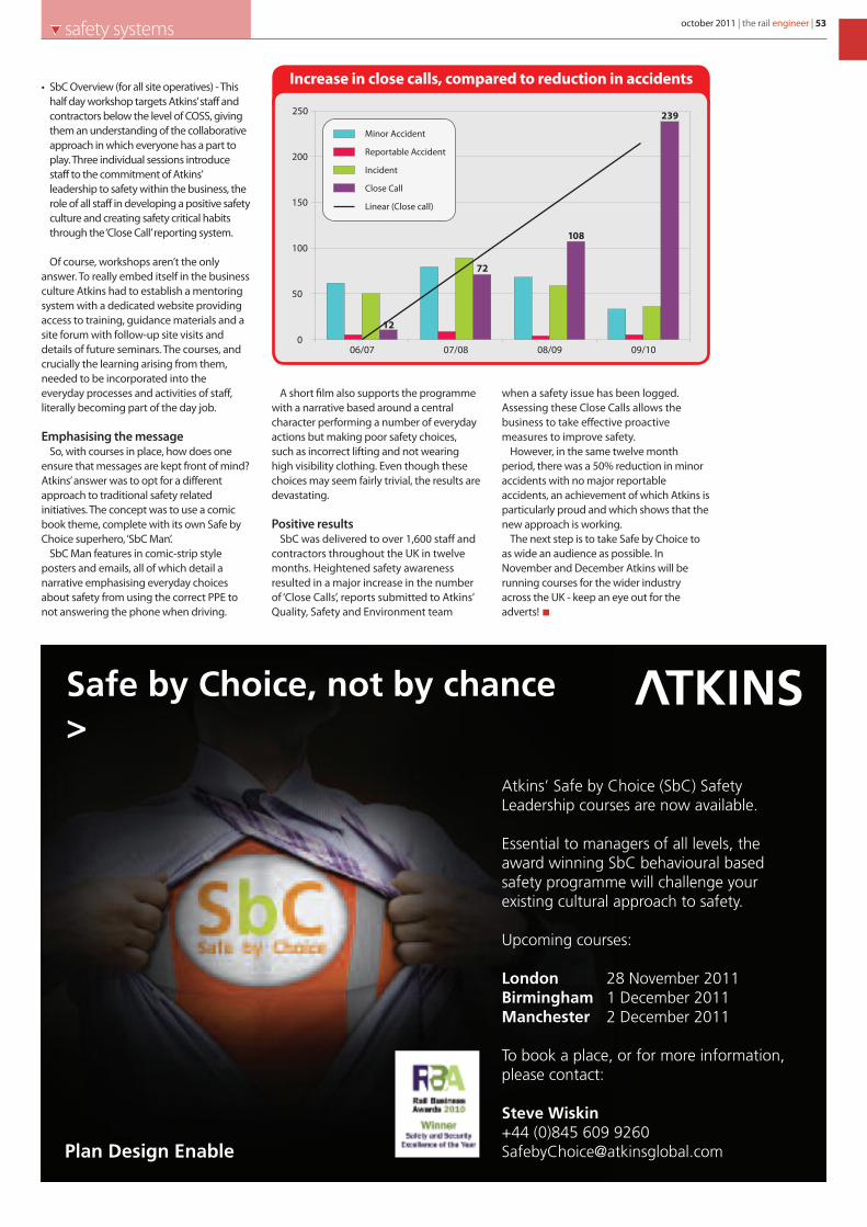
october 2011 | the rail engineer | 53safety systems
• SbC Overview (for all site operatives) - Thishalf day workshop targets Atkins’ staff andcontractors below the level of COSS, givingthem an understanding of the collaborativeapproach in which everyone has a part toplay. Three individual sessions introducestaff to the commitment of Atkins’leadership to safety within the business, therole of all staff in developing a positive safetyculture and creating safety critical habitsthrough the ‘Close Call’ reporting system.
Of course, workshops aren’t the onlyanswer. To really embed itself in the businessculture Atkins had to establish a mentoringsystem with a dedicated website providingaccess to training, guidance materials and asite forum with follow-up site visits anddetails of future seminars. The courses, andcrucially the learning arising from them,needed to be incorporated into theeveryday processes and activities of staff,literally becoming part of the day job.
Emphasising the message So, with courses in place, how does one
ensure that messages are kept front of mind?Atkins’ answer was to opt for a differentapproach to traditional safety relatedinitiatives. The concept was to use a comicbook theme, complete with its own Safe byChoice superhero, ‘SbC Man’.
SbC Man features in comic-strip styleposters and emails, all of which detail anarrative emphasising everyday choicesabout safety from using the correct PPE tonot answering the phone when driving.
A short film also supports the programmewith a narrative based around a centralcharacter performing a number of everydayactions but making poor safety choices,such as incorrect lifting and not wearinghigh visibility clothing. Even though thesechoices may seem fairly trivial, the results aredevastating.
Positive resultsSbC was delivered to over 1,600 staff and
contractors throughout the UK in twelvemonths. Heightened safety awarenessresulted in a major increase in the numberof ‘Close Calls’, reports submitted to Atkins’Quality, Safety and Environment team
when a safety issue has been logged.Assessing these Close Calls allows thebusiness to take effective proactivemeasures to improve safety.
However, in the same twelve monthperiod, there was a 50% reduction in minoraccidents with no major reportableaccidents, an achievement of which Atkins isparticularly proud and which shows that thenew approach is working.
The next step is to take Safe by Choice toas wide an audience as possible. InNovember and December Atkins will berunning courses for the wider industryacross the UK - keep an eye out for theadverts!
Atkins’ Safe by Choice (SbC) Safety Leadership courses are now available.
Essential to managers of all levels, the award winning SbC behavioural based safety programme will challenge your existing cultural approach to safety.
Upcoming courses:
London 28 November 2011Birmingham 1 December 2011Manchester 2 December 2011
To book a place, or for more information, please contact:
Steve Wiskin+44 (0)845 609 9260 [email protected] Design Enable
Safe by Choice, not by chance>
Increase in close calls, compared to reduction in accidents
006/07 07/08 08/09 09/10
50
150
250
100
200
12
72
108
239
Minor Accident
Reportable Accident
Incident
Close Call
Linear (Close call)
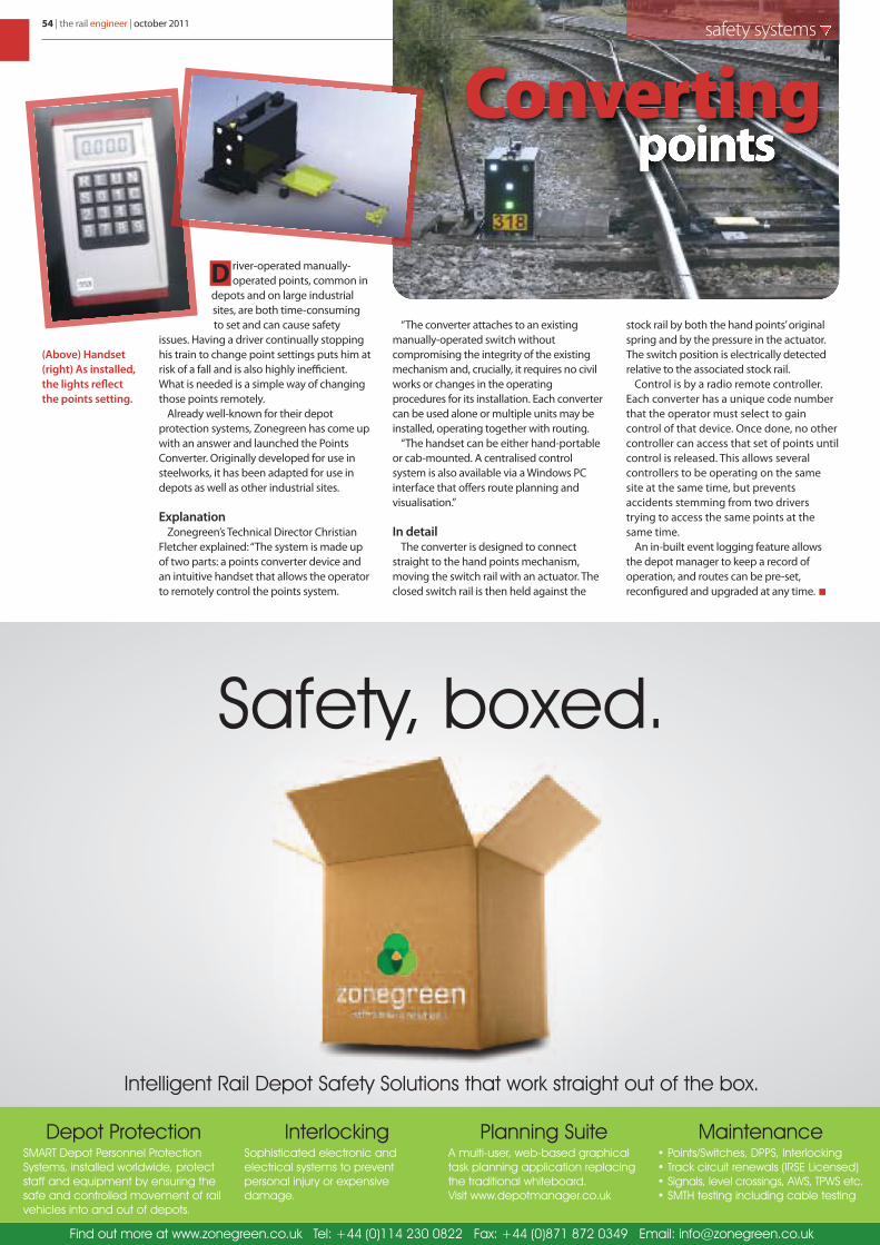
river-operated manually-operated points, common in
depots and on large industrialsites, are both time-consumingto set and can cause safety
issues. Having a driver continually stoppinghis train to change point settings puts him atrisk of a fall and is also highly inefficient.What is needed is a simple way of changingthose points remotely.
Already well-known for their depotprotection systems, Zonegreen has come upwith an answer and launched the PointsConverter. Originally developed for use insteelworks, it has been adapted for use indepots as well as other industrial sites.
ExplanationZonegreen’s Technical Director Christian
Fletcher explained: “The system is made upof two parts: a points converter device andan intuitive handset that allows the operatorto remotely control the points system.
“The converter attaches to an existingmanually-operated switch withoutcompromising the integrity of the existingmechanism and, crucially, it requires no civilworks or changes in the operatingprocedures for its installation. Each convertercan be used alone or multiple units may beinstalled, operating together with routing.
“The handset can be either hand-portableor cab-mounted. A centralised controlsystem is also available via a Windows PCinterface that offers route planning andvisualisation.”
In detailThe converter is designed to connect
straight to the hand points mechanism,moving the switch rail with an actuator. Theclosed switch rail is then held against the
stock rail by both the hand points’ originalspring and by the pressure in the actuator.The switch position is electrically detectedrelative to the associated stock rail.
Control is by a radio remote controller.Each converter has a unique code numberthat the operator must select to gaincontrol of that device. Once done, no othercontroller can access that set of points untilcontrol is released. This allows severalcontrollers to be operating on the samesite at the same time, but preventsaccidents stemming from two driverstrying to access the same points at thesame time.
An in-built event logging feature allowsthe depot manager to keep a record ofoperation, and routes can be pre-set,reconfigured and upgraded at any time.
D
54 | the rail engineer | october 2011 safety systems
General Safety Comapany (Railway
company logo colours and website)
Safety, boxed.
Depot Protection SMART Depot Personnel Protection
Systems, installed worldwide, protect
staff and equipment by ensuring the
safe and controlled movement of rail
vehicles into and out of depots.
InterlockingSophisticated electronic and
electrical systems to prevent
personal injury or expensive
damage.
Planning Suite A multi-user, web-based graphical
task planning application replacing
the traditional whiteboard.
Visit www.depotmanager.co.uk
Maintenance • Points/Switches, DPPS, Interlocking
• Track circuit renewals (IRSE Licensed)
• Signals, level crossings, AWS, TPWS etc.
• SMTH testing including cable testing
Find out more at www.zonegreen.co.uk Tel: +44 (0)114 230 0822 Fax: +44 (0)871 872 0349 Email: [email protected]
Intelligent Rail Depot Safety Solutions that work straight out of the box.
pointsConverting
(Above) Handset(right) As installed,the lights reflectthe points setting.

october 2011 | the rail engineer | 55safety systems
The future’s bright,the future’s ATWS
David Shirresw r i t e r
Schweizer’sMinimel in use.
or over ten years, Track WarningSystems have been hyped as a
track safety and productivity solution.The reality was minimal use and failedpilot schemes. Automatic TrackWarning System (ATWS) installations at17 key locations in 2002 were soonremoved. The Track 02 system lost itssafety approval in 2004 after over ahundred sets had been purchased byNetwork Rail’s Contractors.
Now times are a changing withNetwork Rail’s successful large scaleLOWS (Lookout Operated WarningSystem) initiative. Does this mean abrighter future for Track WarningSystems? With the next generation ofATWS under development, and theMcNulty report requiring the adoptionof more efficient continental practices,it would seem so. the rail engineervisited ATWS suppliers Zöllner andSchweizer to learn more.
Large scale LOWS useZöllner’s Frank Peters states that 230
portable LOWS kits have been suppliedto Network Rail’s maintenance teamsover the past two years. He knows thisequipment is intensively used asZöllner has been closely involved in itsintroduction by providing training, ahotline, servicing, repair and annualrecalibration. Frank commented“Initially we were called out quite a bit,but less so now, as depots get used tothe kit”.
Network Rail’s standard NR/L3/MTC/SE0206 “Introduction and Managementof LOWS Equipment” specifies thecompetence for its use and the supportto be provided by InfrastructureMaintenance Delivery Managers(IMDMs). This includes the need to maplocations to establish a pre-determinedSafe System of Work (SSoW) and toconfirm radio coverage. Training is thesame for a LOWS Controller and aLOWS Lookout. LOWS competence isdeemed to have lapsed if it is not usedwithin 28 days of initial training.Thereafter LOWS must be used at least10 times in the next three months andonce every three months after that.
Network Rail’s successful LOWS
implementation is due to the work ofthe Track Warning Systems (TWS)Steering Group and those in themaintenance organisation who havedriven its introduction. Some depotsimmediately saw its benefits and mademore use of LOWS than others. Nodoubt the use of LOWS will increase as,with large scale use, its benefitsbecome clear to all. The time to set upand test a LOWS SSoW is very similar tothat for a conventional lookout.
Zöllner consider that by far thegreatest use of LOWS is for mobilepatrolling. LOWS lookouts remain staticbut can leapfrog each other as thepatrol moves in accordance with thepre-determined SSoW determined bythe mapping exercise. Previously, it wasoften not practicable for mobileLookouts to maintain the requiredsighting distance and mobileworkgroups accounted for a largepercentage of track fatalities so mobileLOWS use offers a significant safetybenefit.
Other advantages are that, at nightand in fog, there is no need to impose a20 mph TSR as the LOWS Lookout canbe positioned where the train passes.Also the LOWS Lookout need not be onthe rail infrastructure. For example abridge over a steep cutting offersimproved radio coverage, increasedsighting distance and a less hazardoussituation.
The status quo, our greatest competition
Although both Schweizer andZöllner supply Track Warning Systems,Schweizer’s Chris Foreman feels thathis “greatest competitor is the statusquo”. On the Swiss rail network, whichis less than a quarter the UK network,he estimates the use of ATWS to bebetween 50 and 100 per day. BothChris and Frank estimate that ATWSuse in the UK is 5 to 10 per day. Chrisclearly believes large scale use ofATWS would benefit the UK railindustry but feels that currentarrangements do not providesufficient incentive for its use as“Programme Managers have to pay for
ATWS but do not get the financialbenefit from engineering accesssavings”.
Chris Foreman considers that theMcNulty report’s benchmarking UK railagainst European practice should driveincreased use of ATWS. Frank Petersthinks that it’s odd that, although theRIMINI standard requires ATWS to bethe first consideration for Red Zoneworking, its use is a tiny percentage ofRed Zone working. He also feels thatATWS use needs to be consideredearlier in project planning.
Unlike LOWS, ATWS automaticallydetects trains by rail mounted treadles
F
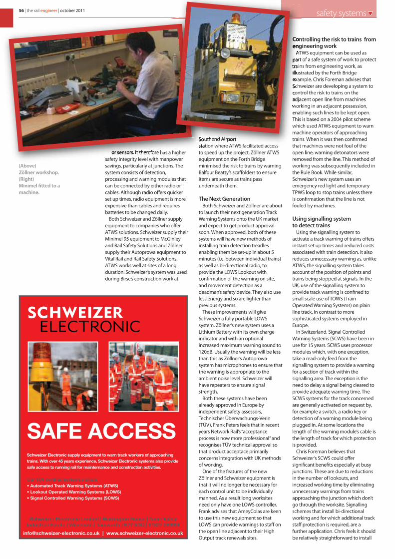
56 | the rail engineer | october 2011 safety systems
or sensors. It therefore has a highersafety integrity level with manpowersavings, particularly at junctions. Thesystem consists of detection,processing and warning modules thatcan be connected by either radio orcables. Although radio offers quickerset up times, radio equipment is moreexpensive than cables and requiresbatteries to be changed daily.
Both Schweizer and Zöllner supplyequipment to companies who offerATWS solutions. Schweizer supply theirMinimel 95 equipment to McGinleyand Rail Safety Solutions and Zöllnersupply their Autoprowa equipment toVital Rail and Rail Safety Solutions.ATWS works well at sites of a longduration. Schweizer’s system was usedduring Birse’s construction work at
Southend Airportstation where ATWS facilitated accessto speed up the project. Zöllner ATWSequipment on the Forth Bridgeminimised the risk to trains by warningBalfour Beatty’s scaffolders to ensureitems are secure as trains passunderneath them.
The Next GenerationBoth Schweizer and Zöllner are about
to launch their next generation TrackWarning Systems onto the UK marketand expect to get product approvalsoon. When approved, both of thesesystems will have new methods ofinstalling train detection treadlesenabling them be set-up in about 5minutes (i.e. between individual trains)as well as bi-directional radio, toprovide the LOWS Lookout withconfirmation of the warning on site,and movement detection as adeadman’s safety device. They also useless energy and so are lighter thanprevious systems.
These improvements will giveSchweizer a fully portable LOWSsystem. Zöllner’s new system uses aLithium Battery with its own chargeindicator and with an optionalincreased maximum warning sound to120dB. Usually the warning will be lessthan this as Zöllner’s Autoprowasystem has microphones to ensure thatthe warning is appropriate to theambient noise level. Schweizer willhave repeaters to ensure signalstrength.
Both these systems have beenalready approved in Europe byindependent safety assessors,Technischer Überwachungs-Verin(TÜV). Frank Peters feels that in recentyears Network Rail’s “acceptanceprocess is now more professional” andrecognises TÜV technical approval sothat product acceptace primarilyconcerns integration with UK methodsof working.
One of the features of the newZöllner and Schweizer equipment isthat it will no longer be necessary foreach control unit to be individuallymanned. As a result long worksitesneed only have one LOWS controller.Frank advises that AmeyColas are keento use this new equipment so thatLOWS can provide warnings to staff onthe open line adjacent to their HighOutput track renewals sites.
Controlling the risk to trains fromengineering work
ATWS equipment can be used aspart of a safe system of work to protecttrains from engineering work, asillustrated by the Forth Bridgeexample. Chris Foreman advises thatSchweizer are developing a system tocontrol the risk to trains on theadjacent open line from machinesworking in an adjacent possession,enabling such lines to be kept open.This is based on a 2004 pilot schemewhich used ATWS equipment to warnmachine operators of approachingtrains. When it was then confirmedthat machines were not foul of theopen line, warning detonators wereremoved from the line. This method ofworking was subsequently included inthe Rule Book. While similar,Schweizer’s new system uses anemergency red light and temporaryTPWS loop to stop trains unless thereis confirmation that the line is notfouled by machines.
Using signalling system to detect trains
Using the signalling system toactivate a track warning of trains offersinstant set up times and reduced costsassociated with train detection. It alsoreduces unnecessary warning as, unlikeATWS, the signalling system takesaccount of the position of points andtrains being stopped at signals. In theUK, use of the signalling system toprovide track warning is confined tosmall scale use of TOWS (TrainOperated Warning Systems) on plainline track, in contrast to moresophisticated systems employed inEurope.
In Switzerland, Signal ControlledWarning Systems (SCWS) have been inuse for 15 years. SCWS uses processormodules which, with one exception,take a read-only feed from thesignalling system to provide a warningfor a section of track within thesignalling area. The exception is theneed to delay a signal being cleared toprovide adequate warning time. TheSCWS systems for the track concernedare generally activated on request by,for example a switch, a radio key ordetection of a warning module beingplugged in. At some locations thelength of the warning module’s cable isthe length of track for which protectionis provided.
Chris Foreman believes thatSchweizer’s SCWS could offersignificant benefits especially at busyjunctions. These are due to reductionsin the number of lookouts, andincreased working time by eliminatingunnecessary warnings from trainsapproaching the junction which don’tgo through the worksite. Signallingschemes that install bi-directionalworking and for which additional trackstaff protection is required, are afurther application. Chris feels it shouldbe relatively straightforward to install
Schweizer Electronic Limited | Warrington House | Tame ValleyIndustrial Estate | Wilnecote | Tamworth | B77 5DQ | 01827 289996
[email protected] | www.schweizer-electronic.co.uk
SAFE ACCESSSchweizer Electronic supply equipment to warn track workers of approaching
trains. With over 45 years experience, Schweizer Electronic systems also provide
safe access to running rail for mainternance and construction activities.
• Automated Track Warning Systems (ATWS)
• Lookout Operated Warning Systems (LOWS)
Our TUV certified systems include:
• Signal Controlled Warning Systems (SCWS)
(Above)Zöllner workshop.(Right)Minimel fitted to amachine.

october 2011 | the rail engineer | 57safety systems
The New EZiCAT i600, i650 & LOGiCAT Software now available! !"#$%&!'()*+&!',&*"+%&'-.%#/+.$'/&%0$.-.12
Provides a unique data capture and on board memory function,supporting operations management initiatives to increase onsite safety and identify operator training needs.
Visit %#(-&!&/&%/+.$3%.3)4 for more information.
56+7A8'+9::';&#/)*&,'<'(&$&=/,'>''?#/#'%#@/)*&'''''%#@#(+-+/+&,'A',/.*&''''')@'/.'B:'0.)*,'.;'),&'NEW>''C+*&-&,,'D-)&/../0?#/#'''''T*#$,;&*' E'ET F? G?>''E/#*/,'+$'H.I&*'J.!&>' )/.K#/+%'%.$/*.-,>''L$M()+-/'/&,/';)$%/+.$>''E&*"+%&'?)&'L$!+%#/.*>''N#O#*!'6.$&>''E+1$#-'E/*&$1/0'L$!+%#/.*'''''PEELQ>''?&@/0'L$!+%#/+.$'''''(EZiCAT i650 model only)
>''N+10'%.$/*#,/'R7?',%*eenAPPR
OV
ED
NETWORK RAILNETWORK RAIL
SCWS in the UK, especially if initial productapproval was confined to a read-only feedfrom the signalling system.
The Austrian version of SCWS uses theGSM-R infrastructure to receive requests fortrack warnings and activate warningmodules. Frank Peters advises that thisproject has been under development for tenyears and saw its first pilot application thisyear. It quickly establishes warning systemsfor any type of worksite, has no radioreception issues and largely eliminateslineside cabling forwarning systems. It ishowever a long termsolution. A moreimmediate option isthe use of GSM-R fortrack warning systemsto eliminate the effectsof radio black spots.
A new dawnFor ten years, UK use
of track warning systemshas been minimal. A newdawn is now breakingwith Network Rail’s LOWSuse solving the problemof mobile patrolling withsignificant safety andproductivity benefits.Although there is still a resistance to the useof automatic train detection, this must surelychange with McNulty’s challenge to improvethe productivity of engineering access bylearning, in part, from European railways .
The difficulties of introducing automaticsystems, including detection by thesignalling system, should not beunderestimated as many factors reinforcethe status quo. Tackling this includes the
need for cultural change, gaining workforceconfidence, product approval andappropriate contractual incentives. The signsare that Network Rail now has both thecommitment and ability to meet thischallenge for which its large scale use ofLOWS should provide a springboard.Schweizer and Zöllner are also key playerswho can provide European provenequipment to ensure that soon the statusquo will no longer be a serious competitor.
(Left)LOWS Lookout(Right)Zöllner controlunit.
58 | the rail engineer | october 2011 senior appointments

!"#$%&#"'(%)%*""+,-.%/"#01#2%!"%!34%/'!'#4
!"#$%&' ()*)+%",-.'% ()*)+%",
546#4%.",-.%(*17489%:#4%$"';
-'#"/ 0"#12 ., ) ,1&&%,,314 &#*'")&'.*+ 4)*/6 .*&#"2#")'.*+ 7).46 8#*,'"1&'.#* )*9 !4)*' :."% ,%";.&%, <.'= ) '1"*#;%" #3 >?@ 5.44.#*A B2%")'.*+ *)'.#*)44/ <% )"% ) 9/*)5.&6 ,#41'.#* 9".;%* #"+)*.,)'.#* <.'= )* %*;.)C4% &4.%*' C),% )*9 )* %D&%44%*' "%21')'.#* 3#" 9%4.;%".*+ Ȍ%D 2"#$%&', .* C1.49.*+6 &.;.4 %*+.*%%".*+ )*9 '")&E %*;."#*5%*', F.*&419.*+ 9%,.+* )*9 C1.49GA
B1" &#*'.*1%9 ,1&&%,, .* '=%,% 9.,&.24.*%, =), &"%)'%9 %D&.'.*+ *%< #22#"'1*.'.%, <.'=.* #1" C1,.*%,,A H52#"')*' '# 1, ., /#1" )''.'19%A -1&&%,,314 &)*9.9)'%, )"% 4.E%4/ '# =);% )* %*+.*%%".*+ C)&E+"#1*9 <.'= ) 2"#;%* )C.4.'/ '# 9%4.;%" 2"#$%&', ,)3%4/6 '# 2"#+")55% )*9 '# Ȍ%'%4/ 5%%' '=% *%%9, #3 #1" &4.%*',A
H* "%'1"* <% #33%" 5)"E%' 4%)9.*+ ,)4)".%,6 "%4#&)'.#* %D2%*,%, F<=%"% )224.&)C4%G )*9 #'=%" C%*%I', ),,#&.)'%9 <.'= ) ,1&&%,,314 )*9 3#"<)"9 '=.*E.*+ 4)*/A
H3 /#1J"% 4##E.*+ 3#" ) *%< #22#"'1*.'/ )*9 <#149 4.E% '# <#"E <.'= )* %,')C4.,=%9 4)*/ '=)'J, %D&.'.*+6 &=)44%*+.*+ )*9 +#.*+ 24)&%,6 '=%* 24%),% ,1C5.' ) ,=#"' .*'"#91&'.#* )C#1' /#1",%43 )*9 /#1" &)"%%" '# 9)'% '#K ,'L,'#"/+"#12A&#A1E
-'#"/ 0"#12 M N1"+= 7#)9 H*91,'".)4 O,')'% M 8)"4.,4% M 815C".) M 8PQ RSP M T%4K @UQQV WX@???

The start of something new...Balfour Beatty Rail has embarked on a journey to develop and enhance its market-leading ClearRoute™ clearance software to ensure it continues to meet the changing needs of the future rail market.
ClearRoute™ has been a trusted product for carrying out clearance and gauging analysis for many years. It is the tool of preference for permanent way and gauging engineers in the UK and international markets.
ClearRoute2™ will provide users with improved functionality, greater user flexibility and faster operating speeds.
The first fully validated release of ClearRoute2™ will be taking place in October 2011.
Find out more...To coincide with this release Balfour Beatty Rail will be hosting a series of roadshows across the country to demonstrate the new product and highlight the benefits of ClearRoute2™.
Roadshows will be taking place throughout October at the following locations:
Glasgow Tuesday 11th October Manchester Thursday 13th October Birmingham Tuesday 18th October Bristol Tuesday 25th October London Thursday 27th October ndards and settingsTo register to attend one of the above roadshows or for further information contact:Andy Willetts Software Sales & Product ManagerTel: +44 (0) 771 422 2582Email: [email protected]
LaserRail
learRoute™C 2
www.bbrail.co.uk
Related Documents


