Doc 9906-AN/472 THE QUALITY ASSURANCE MANUAL FOR FLIGHT PROCEDURE DESIGN VOLUME 5 – VALIDATION OF INSTRUMENT FLIGHT PROCEDURES Notice to Users This document is an unedited advance version of an ICAO publication as approved, in principle, by the Secretary General, which is rendered available to the public for convenience. The final edited version may still undergo alterations in the process of editing. Consequently, ICAO accepts no responsibility or liability of any kind should the final text of this publication be at variance from that appearing here.

Welcome message from author
This document is posted to help you gain knowledge. Please leave a comment to let me know what you think about it! Share it to your friends and learn new things together.
Transcript
Doc 9906-AN/472
THE QUALITY ASSURANCE MANUAL FOR
FLIGHT PROCEDURE DESIGN
VOLUME 5 – VALIDATION OF INSTRUMENT FLIGHT PROCEDURES
Notice to Users
This document is an unedited advance version of an ICAO publication as approved, in
principle, by the Secretary General, which is rendered available to the public for
convenience. The final edited version may still undergo alterations in the process of editing.
Consequently, ICAO accepts no responsibility or liability of any kind should the final text of
this publication be at variance from that appearing here.
Validation of Instrument Flight Procedures – Volume 5 2
Advance edition (unedited)
3 Validation of Instrument Flight Procedures – Volume 5
Preface
The Quality Assurance Manual for Flight Procedure Design (Doc 9906) consists of six volumes:
Volume 1 – Flight Procedure Design Quality Assurance System;
Volume 2 – Flight Procedure Designer Training;
Volume 3 – Flight Procedure Design Software Validation;
Volume 4 – Flight Procedures Design Construction (to be developed);
Volume 5 – Validation of Instrument Flight Procedures; and
Volume 6 – Flight Validation Pilot Training and Evaluation
Instrument flight procedures based on conventional ground-based navigational aids have always
necessitated a high level of quality control. However, with the implementation of area navigation and
associated airborne database navigation systems, even small errors in data could lead to catastrophic
results. This significant change in data quality requirements (accuracy, resolution and integrity) has
led to the requirement of a systemic quality assurance process (often part of a State Safety
Management System). The Procedures for Air Navigation Services — Aircraft Operations (PANS-
OPS, Doc 8168) Volume II, Part 1, Section 2, Chapter 4, Quality Assurance), refers to this manual
and requires that the State take measures to ‘control’ the quality of the processes associated with the
construction of instrument flight procedures. This manual aims to provide guidance in attaining these
stringent requirements. All six volumes address crucial areas related to the attainment, maintenance
and continual improvement of procedure design quality and flight validation (FV). Data quality
management, procedure designer training, and validation of software are all integral elements of a
quality assurance system.
Volume 1 – Flight Procedure Design Quality Assurance System, provides guidance for quality
assurance in the procedure design processes, such as procedure design documentation, verification and
validation methods, guidelines about the acquisition/processing of source information/data. It also
provides a generic process flow diagram for the design and the implementation of flight procedures.
Volume 2 – Flight Procedure Designer Training, provides guidance for the establishment of flight
procedure designer training. Training is the starting point for any quality assurance programme. This
volume provides guidance for the establishment of a training programme.
Volume 3 – Flight Procedure Design Software Validation, provides guidance for the validation (not
certification) of procedure design tools, notably with regard to criteria.
Volume 4 – Flight Procedures Design Construction (to be incorporated later).
Volume 5 – Validation of Instrument Flight Procedures, provides guidance for conducting validation
of instrument flight procedures, including safety, flyability and design accuracy.
Volume 6 – Flight Validation Pilot Training and Evaluation, provides guidance for the establishment
of flight procedure validation pilot training. Training is the starting point for any quality assurance
system. This volume provides guidance for the establishment of a training programme.
Note.–: In the independent volumes, when a reference is made to the term "manual", without any
further specification, it is presumed to refer to the present volume of the Quality Assurance Manual
for Flight Procedure Design.

Validation of Instrument Flight Procedures – Volume 5 4
Table of contents
Preface .............................................................................................................................................. 3
Abbreviations .................................................................................................................................... 5
Definitions ......................................................................................................................................... 6
Foreword ........................................................................................................................................... 7
1. The Validation process ............................................................................................................... 9
1.1. The need for validation ........................................................................................................ 9
1.2. Validation Process ............................................................................................................... 9
1.3. Validation Report and Documentation ................................................................................. 9
1.4. Validation process description ........................................................................................... 11
1.5. Preparation for validation .................................................................................................. 13
1.5.1. Procedure package ...................................................................................................... 13
1.5.2. Flight inspection ......................................................................................................... 13
1.5.3. Data integrity and ARINC encoding requirements ...................................................... 13
2. Step by step description of activities within the process ............................................................ 15
2.1. Step 1, Conduct independent procedure design review .................................................. 15
2.1.1. Confirm correct application of criteria ........................................................................ 15
2.1.2. Confirm data accuracy and integrity............................................................................ 15
2.1.3. Verify mitigations for deviations from design criteria ................................................. 15
2.1.4. Verify a draft chart (if required) is provided and is correct .......................................... 15
2.1.5. Confirm correct FMS behaviour using desktop software simulation tools (if required) 15
2.1.6. Perform obstacle assessment with State-approved ground-based methods (if required) 16
2.2. Step 2, Conduct Pre-flight Validation ............................................................................. 16
2.2.1. Conduct Inventory and Review IFP Package ............................................................... 16
2.2.2. Evaluate data and coding ............................................................................................ 17
2.2.3. Review special operational and training requirements ................................................. 17
2.2.4. Document the results of the Pre-flight Validation ........................................................ 17
2.2.5. Coordinate operational issues (if flight evaluation is required) .................................... 18
2.3. Step 3, Conduct Simulator Evaluation ............................................................................ 18
2.3.1. Assess Flyability and Human Factor ........................................................................... 19
2.3.2. Document the results of the flight simulator evaluation ............................................... 20
2.4. Step 4, Conduct Flight Evaluation .................................................................................. 20
2.4.1. Verify data ................................................................................................................. 21
2.4.2. Assess obstacles ......................................................................................................... 22
2.4.3. Assess Flyability and Human Factor ........................................................................... 22
2.4.4. Conduct associated validation tasks ............................................................................ 22
2.4.5. Verify chart depiction and details ................................................................................ 23
2.4.6. Record flight validation .............................................................................................. 23
2.5. Step 5, Produce Validation Report .................................................................................. 24
Appendix A - Obstacle Assessment .............................................................................................. 25
Verification of Minimum Obstacle Clearance (MOC) .................................................................. 25
Appendix B - Human Factors ....................................................................................................... 27
Appendix C – Validation Templates for Fixed Wing Aircraft ....................................................... 28
C.2 Simulator Evaluation Checklist - Fixed Wing ........................................................................ 30
C.3 Flight evaluation Checklist - Fixed Wing............................................................................... 31
C.4 Validation Report Checklist - Fixed Wing ............................................................................. 33
Appendix D – Validation Templates for Helicopters ..................................................................... 34
D.1 Pre-Flight Validation Checklist - Helicopters ........................................................................ 35
D.2 Simulator Evaluation Checklist - Helicopters ........................................................................ 36
D.3 Flight Evaluation Checklist - Helicopters .............................................................................. 37
D.4 Validation Report Checklist - Helicopters ............................................................................. 39
5 Validation of Instrument Flight Procedures – Volume 5
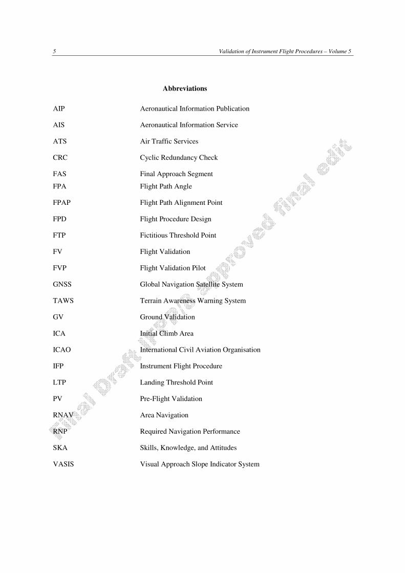
Abbreviations
AIP Aeronautical Information Publication
AIS Aeronautical Information Service
ATS Air Traffic Services
CRC Cyclic Redundancy Check
FAS
FPA
Final Approach Segment
Flight Path Angle
FPAP Flight Path Alignment Point
FPD Flight Procedure Design
FTP Fictitious Threshold Point
FV Flight Validation
FVP Flight Validation Pilot
GNSS Global Navigation Satellite System
TAWS Terrain Awareness Warning System
GV Ground Validation
ICA Initial Climb Area
ICAO International Civil Aviation Organisation
IFP Instrument Flight Procedure
LTP Landing Threshold Point
PV Pre-Flight Validation
RNAV Area Navigation
RNP Required Navigation Performance
SKA Skills, Knowledge, and Attitudes
VASIS Visual Approach Slope Indicator System
Validation of Instrument Flight Procedures – Volume 5 6
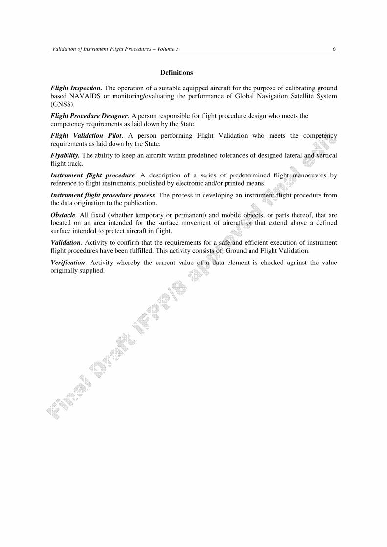
Definitions
Flight Inspection. The operation of a suitable equipped aircraft for the purpose of calibrating ground
based NAVAIDS or monitoring/evaluating the performance of Global Navigation Satellite System
(GNSS).
Flight Procedure Designer. A person responsible for flight procedure design who meets the
competency requirements as laid down by the State.
Flight Validation Pilot. A person performing Flight Validation who meets the competency
requirements as laid down by the State.
Flyability. The ability to keep an aircraft within predefined tolerances of designed lateral and vertical
flight track.
Instrument flight procedure. A description of a series of predetermined flight manoeuvres by
reference to flight instruments, published by electronic and/or printed means.
Instrument flight procedure process. The process in developing an instrument flight procedure from
the data origination to the publication.
Obstacle. All fixed (whether temporary or permanent) and mobile objects, or parts thereof, that are
located on an area intended for the surface movement of aircraft or that extend above a defined
surface intended to protect aircraft in flight.
Validation. Activity to confirm that the requirements for a safe and efficient execution of instrument
flight procedures have been fulfilled. This activity consists of Ground and Flight Validation.
Verification. Activity whereby the current value of a data element is checked against the value
originally supplied.

7 Validation of Instrument Flight Procedures – Volume 5
Foreword
Instrument flight procedures are an integral component in the airspace structure. Thousands of aircraft
fly instrument departure, arrival, or approach procedures to airports around the world. As such the
safety and efficiency of these procedures is important and the development of these procedures
should be subject to a quality assurance system.
The purpose of validation is to obtain a qualitative assessment of procedure design including obstacle,
terrain and navigation data, and provide an assessment of flyability of the procedure so as to ensure a
proper standard for all publications.
This volume provides a detailed description of the validation process of the instrument flight
procedures. The validation process is subdivided into Ground Validation and Flight Validation.
The objective of conducting validation is to ensure safety, data accuracy and integrity and flyability of
the instrument flight procedure. The validation process applies to fixed wing and helicopter instrument
flight procedures.
Volume 6 of Doc. 9906 contains recommended qualifications and training, as well as guidance
concerning the skills, knowledge and attitudes (SKA) to be addressed in training and evaluation of
flight validation pilots and should be considered complementary to Volume 5.
The terms “flight validation” and “flight inspection” are often misinterpreted as the same concept.
Flight validation and flight inspection are separate activities that, if required, may or may not be
undertaken by the same entity.
a) Flight validation is concerned with factors other than the performance of the navigation aid or
system that may affect the suitability of the procedure for publication, as detailed in PANS-
OPS, Volume II, Part I, Section 2, Chapter 4, Quality Assurance.
b) Flight inspection is conducted with the purpose of confirming the ability of the navigation
aid(s)/system upon which the procedure is based, to support the procedure, in accordance with
the Standards in Annex 10 — Aeronautical Telecommunications and guidance in the Manual
on the Testing of Radio Navigation Aids (Doc 8071). Personnel performing flight inspection
duties should be qualified and certified in accordance with Doc 8071, Volume I, Testing of
Ground-Based Radio Navigation Systems.
A procedure design organization may not have the expertise necessary to determine under which
conditions flight validation and/or flight inspection may be necessary. For this reason it is
recommended that a review by the flight validation and/or flight inspection organizations be included
in the State’s procedure design process flow. The State is responsible for the overall performance of
the procedure, as well as of its quality and suitability for publication.
PANS-OPS, Volume II, Part I, Section 2, Chapter 4, Quality Assurance requires the State to have a
written policy requiring minimum qualifications and training for flight validation pilots, including
those flight inspection pilots that perform flight validation of instrument flight procedures. This policy
also includes standards for the required competency level for flight validation pilots.
The pilot-in-command is responsible for the safe operation of the flight in accordance with applicable
State regulations; however, due to the nature of flight validation requirements, it is understood that
some of the regulations related to altitude and aircraft positioning must be waived by the State in order
to properly validate published procedures.
The implementation of procedures is the responsibility of Contracting States, which implies that the
State authorities have the final responsibility for procedures published within their territory. The
validation process may be carried out by the States themselves or delegated by States to third parties
(ATS providers, private companies, other States, etc.). The Procedures for Air Navigation Services—

Validation of Instrument Flight Procedures – Volume 5 8
Aircraft Operations (PANS-OPS, Doc 8168) requires that the States take measures to perform
validation of instrument flight procedures to ensure the quality and safety of the procedure design for
its intended use before publication. In all cases, including when third parties are involved in any step
of the validation process, States carry the ultimate responsibility for the procedures published in their
national Aeronautical Information Publication (AIP). This manual has been developed to provide
guidance to Contracting States in developing a validation process to ensure the quality of the flight
procedures published by them. The manual provides a means, but it is not the only one, for the
implementation of the validation process. Latitude is permitted to comply with local requirements.
The manual may be of interest to any person or organization involved in the validation domain.
9 Validation of Instrument Flight Procedures – Volume 5
1. The Validation process
1.1. The need for validation
The purpose of validation is to obtain a qualitative assessment of procedure design including obstacle,
terrain and navigation data, and provides an assessment of flyability of the procedure.
The validation is one of the final quality assurance steps in the procedure design process for
instrument flight procedures (IFP) and is essential before the procedure design documentation is
issued as part of the Integrated Aeronautical Information Package.
1.2. Validation Process
The full validation process includes Ground validation and Flight validation.
Ground Validation must always be undertaken. It encompasses a systematic review of the steps and
calculations involved in the procedure design as well as the impact on flight operations by the
procedure. It must be performed by a person(s) trained in Flight Procedure Design and with
appropriate knowledge of Flight Validation issues.
Ground validation consists of an independent IFP design review and a pre-flight validation. Flight
validation consists of a flight simulator evaluation and an evaluation flown in an aircraft. An overview
of the necessary steps in the validation process can be found in figure 1-1. The validation process of
IFP(s) must be carried out as part of the initial IFP design as well as an amendment to an existing IFP.
If the State can verify through Ground Validation the accuracy and completeness of all obstacle and
navigation data considered in the procedure design, and any other factors normally considered in the
Flight Validation, then the Flight Validation requirement may be dispensed with.
Flight Validation is required under the following conditions:
a) the flyability of a procedure cannot be determined by other means;
b) the procedure requires mitigation for deviations from design criteria;
c) the accuracy and/or integrity of obstacle and terrain data cannot be determined by other
means;
d) if new procedures differ significantly from existing procedures; and
e) Helicopter PinS procedures.
1.3. Validation Report and Documentation
It is the responsibility of the State to determine the minimum content and retention policy of
documentation. As part of the flight procedure design documentation, a validation report should be
completed at the end of the process including reports of individual steps performed. The minimum
suggested requirements are the name and signature of the validation experts (Flight Procedure
Designer and/or Flight Validation Pilot), date, activities performed, type of simulator or aircraft, any
findings and Flight Validation Pilot comments and operational recommendations. If a Flight
Validation is performed, a printed graphic and/or electronic file of sufficient detail that depicts the
flight track flown must be included in the report. Such file should show procedure fixes, the maximum
and minimum altitude, ground speed, climb rate and climb gradient and a comparison of the actual
track flown with the desired track of the instrument flight procedure.

Validation of Instrument Flight Procedures – Volume 5 10
The validation process flow diagram in the context of the flight procedure design process is shown as
follows:
Figure 1-1 Validation process flow chart
11 Validation of Instrument Flight Procedures – Volume 5
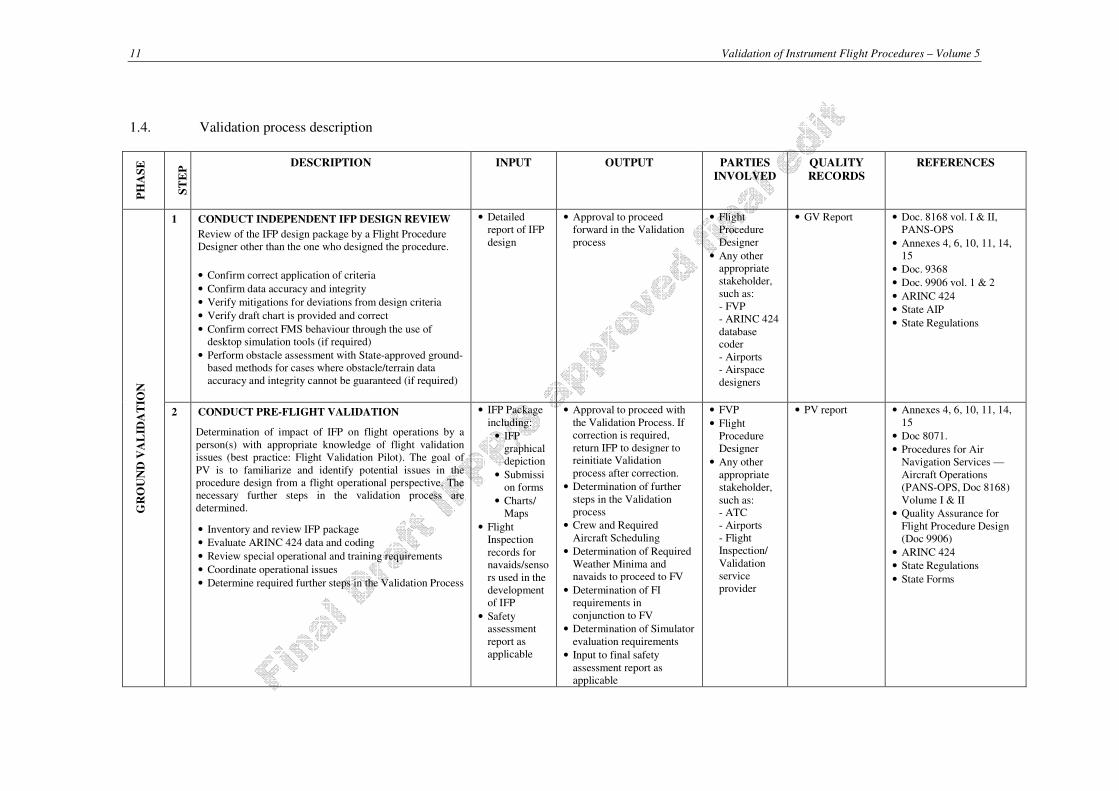
1.4. Validation process description P
HA
SE
ST
EP
DESCRIPTION INPUT OUTPUT PARTIES
INVOLVED
QUALITY
RECORDS
REFERENCES
GR
OU
ND
VA
LID
AT
ION
1 CONDUCT INDEPENDENT IFP DESIGN REVIEW
Review of the IFP design package by a Flight Procedure
Designer other than the one who designed the procedure.
• Confirm correct application of criteria
• Confirm data accuracy and integrity
• Verify mitigations for deviations from design criteria
• Verify draft chart is provided and correct
• Confirm correct FMS behaviour through the use of
desktop simulation tools (if required)
• Perform obstacle assessment with State-approved ground-
based methods for cases where obstacle/terrain data
accuracy and integrity cannot be guaranteed (if required)
• Detailed
report of IFP
design
• Approval to proceed
forward in the Validation
process
• Flight
Procedure
Designer
• Any other
appropriate
stakeholder,
such as:
- FVP
- ARINC 424
database coder
- Airports
- Airspace
designers
• GV Report • Doc. 8168 vol. I & II,
PANS-OPS
• Annexes 4, 6, 10, 11, 14,
15
• Doc. 9368
• Doc. 9906 vol. 1 & 2
• ARINC 424
• State AIP
• State Regulations
2 CONDUCT PRE-FLIGHT VALIDATION
Determination of impact of IFP on flight operations by a
person(s) with appropriate knowledge of flight validation
issues (best practice: Flight Validation Pilot). The goal of
PV is to familiarize and identify potential issues in the
procedure design from a flight operational perspective. The
necessary further steps in the validation process are
determined.
• Inventory and review IFP package
• Evaluate ARINC 424 data and coding
• Review special operational and training requirements
• Coordinate operational issues
• Determine required further steps in the Validation Process
• IFP Package
including:
• IFP
graphical
depiction
• Submissi
on forms
• Charts/
Maps
• Flight
Inspection
records for navaids/senso
rs used in the
development
of IFP
• Safety assessment
report as
applicable
• Approval to proceed with
the Validation Process. If
correction is required,
return IFP to designer to reinitiate Validation
process after correction.
• Determination of further
steps in the Validation
process
• Crew and Required
Aircraft Scheduling
• Determination of Required
Weather Minima and navaids to proceed to FV
• Determination of FI
requirements in
conjunction to FV
• Determination of Simulator
evaluation requirements
• Input to final safety
assessment report as
applicable
• FVP
• Flight
Procedure
Designer
• Any other
appropriate
stakeholder,
such as: - ATC
- Airports
- Flight
Inspection/
Validation
service
provider
• PV report • Annexes 4, 6, 10, 11, 14,
15
• Doc 8071.
• Procedures for Air
Navigation Services —
Aircraft Operations
(PANS-OPS, Doc 8168)
Volume I & II
• Quality Assurance for
Flight Procedure Design
(Doc 9906)
• ARINC 424
• State Regulations
• State Forms

Validation of Instrument Flight Procedures – Volume 5 12
FL
IGH
T V
AL
IDA
TIO
N
3 CONDUCT SIMULATOR EVALUATION
Recommended step for complex procedures or procedures
requiring waiver/mitigation for deviations from design
criteria.
• Verify chart depictions and details
• Assess flyability and Human Factors
• Conduct associated validation tasks
• Record Flight Validation.
• Document the results.
• IFP graphical
depiction
• ARINC 424
IFP Database
• Flyability validation
• Input to final safety
assessment report as
applicable
• Recorded data
• Findings and operational
mitigations
• FVP
• Flight
Procedure
Designer as appropriate
• Flight Simulator
Evaluation
report
• Findings and
operational
mitigations
• Quality Assurance
Manual for Flight
Procedure Design (Doc
9906)
4 CONDUCT FLIGHT EVALUATION
Perform flight evaluation in order to:
• Verify Data
• Verify chart depictions and details
• Assess Obstacle infrastructure
• Assess airport infrastructure
• Assess flyability and Human Factors
• Conduct associated validation tasks
• Record Flight Validation
• FV Package
• SIM Evaluation
Report (if
available)
• Validated IFP
• Findings and operational mitigations
• Input to final safety
assessment report as
applicable
• Recorded data
• FVP
• Flight Procedure
Designer as
appropriate
• Findings and
operational
mitigations
• Recorded data
• Manual on Testing of
Radio Navigation Aids
(Doc 8071)
• Quality Assurance
Manual for Flight
Procedure Design (Doc
9906)
• State Depiction Standard
• Procedures for Air
Navigation Services –
Aircraft Operations
• (PANS-OPS, Doc 8168)
Volume II
GR
OU
ND
VA
LID
AT
ION
5 PRODUCE VALIDATION REPORT
This final step is to assure proper completeness of all forms
and reports to validate the entire FPD package. The
validation report should consist of individual reports of all
steps performed in the validation process.
• Findings and
operational
mitigations
• Recorded
data
• Validation report
• Flight Inspection report
(when performed)
• FVP and/or
• Flight
Procedure
Designer
• GV Report
• FV report
• Flight
Inspection
report (when
performed)
• Quality Assurance
Manual for Flight
Procedure Design (Doc
9906)
• State Forms

13 Validation of Instrument Flight Procedures – Volume 5
1.5. Preparation for validation
This paragraph describes various activities that should be performed prior to the validation process.
1.5.1. Procedure package
The procedure package, provided by the Procedure Design Service Provider, must contain the following
minimum data in an acceptable format to conduct a validation.
The IFP package includes:
a) IFP Summary;
b) Proposed Instrument Procedure Chart/Depiction of sufficient detail to safely navigate and
identify significant terrain, obstacles and obstructions;
c) Proposed ARINC 424 path terminators (for PBN procedures only);
d) List of relevant obstacles, Identification and description of controlling obstacles and obstacles
otherwise influencing the design of the procedure, Waypoint Fix Lat/Long, Procedural
Tracks/Course, Distances and Altitudes;
e) Airport infrastructure information, such as visual aids (ALS, VASI);
f) Information on aerodrome obstacle limitation/safeguarding processes applied;
g) Any special local operational procedure (e.g., noise abatement, non-standard traffic patterns,
lighting activation);
h) Detailed listing of deviations from design criteria and proposed mitigation;
i) For non-standard IFP: training, operational or equipment procedure specific requirements; and
j) Appropriate validation checklist and report forms.
1.5.2. Flight inspection
Flight inspection may be required to assure that the appropriate navigation system (radio navigation
aid/navigation sensor, GBAS data broadcast and/or Final Approach Segment (FAS) data) adequately
supports the procedure. Flight Inspection is carried out as part of the program detailed in ICAO Doc. 8071
or equivalent State document. Flight inspection must be performed by a qualified flight inspector using a
suitably equipped aircraft.
1.5.3. Data integrity and ARINC encoding requirements
Flight procedures to be validated should be contained in the suitable navigation system (i.e. FMS). The
procedure may be on a pre-production custom navigation database. It could be downloaded from an
electronic media with adequate data integrity protection such as CRC wrapping. If no other means exist
manual entry is permissible if sufficient mitigation means have been considered and implemented. All
procedure coding data must originate from the official data source.
1.5.3.1. Custom navigation database (Preferred Method).
A navigation database can be customized by an official database supplier to include procedures for flight
validation. A customized navigation database is the most desirable source because it will contain a normal
operational navigation database and new official source coded flight procedures for validation/inspection.
The custom navigation database should be updated on a periodic schedule.

Validation of Instrument Flight Procedures – Volume 5 14
1.5.3.2. Electronic media
Some procedure design tools output an electronic ARINC 424 code of the final procedure that can be
input to commercial aircraft Flight Management Systems. This process, when used with cyclic
redundancy checks, ensures that the procedure design remains unchanged through the final production
chain thus ensuring a high degree of data integrity.
1.5.3.3. Manual entry
This method of entry should be limited to LNAV procedures only. It should be used sparingly and
requires additional verification steps to confirm proper data entry. If the navigation system used allows
manual input of ARINC path/terminators they should be used. It is recommended that the coded
procedure provided by an official database supplier be used as soon as available, to confirm appropriate
coding prior to public use.

15 Validation of Instrument Flight Procedures – Volume 5
2. Step by step description of activities within the process
The Validation process consists of Ground Validation and Flight Validation. Ground Validation must
always be performed. Each phase consists of several important steps as illustrated in figure 1-1. The
following subsections reflect all the steps of the process flow shown in figure 1-1 and provide additional
comments and explanations.
2.1. Step 1, Conduct independent procedure design review
A flight procedure designer other than the one who designed the procedure must perform this step. The
designer can be assisted by specialists in other fields of expertise as necessary.
2.1.1. Confirm correct application of criteria
The use of the correct design criteria in PANS-OPS vol. II or Doc. 9905 and their correct application
should be assured. This can be achieved by assessing and recalculating every single element of the
procedure design in accordance with Doc. 9906 vol. 1 or by performing selected checks and calculations
as appropriate.
2.1.2. Confirm data accuracy and integrity
The origin of any data (airport, navigation aids, waypoints, obstacles, terrain) should be known. Using
data from a known source usually allows the accuracy and the integrity of the data to be determined. If
data from unknown sources is used or if data accuracy and/or integrity cannot be adequately determined,
the data should be validated. This can be done through Flight Validation or through State-approved
ground-based methods.
2.1.3. Verify mitigations for deviations from design criteria
If deviations from procedure design criteria are used, mitigations must provide an acceptable level of
safety. A Flight Evaluation should be performed to verify the acceptability of previously performed safety
studies.
2.1.4. Verify a draft chart (if required) is provided and is correct
A draft chart is required to conduct a Flight Validation. It should be verified that a draft chart is provided
and contains the required elements to perform the Flight Validation efficiently.
2.1.5. Confirm correct FMS behaviour using desktop software simulation tools (if required)
The correct translation of a procedure into ARINC 424 code can initially be assessed with a desktop
simulation tool. Such tools provide feedback of the correct selection of ARINC 424 path terminators as
well as any issues with the choice of waypoint positions and segment lengths (e.g. route discontinuity).

Validation of Instrument Flight Procedures – Volume 5 16
2.1.6. Perform obstacle assessment with State-approved ground-based methods (if required)
For cases where obstacle and/or terrain data accuracy and/or integrity cannot be guaranteed, ground-based
obstacle assessment methods can provide an alternative to an assessment with an aircraft. Such ground-
based methods should be approved by the State and should provide a defined minimum level of accuracy
as determined by the State.
2.2. Step 2, Conduct Pre-flight Validation
Pre-flight Validation must be conducted by a person(s) trained in flight procedure design and with
appropriate knowledge of Flight Validation issues. This may be a joint activity by flight procedure
designers and pilots. The required qualification for pilots involved in the pre-flight validation step must
be determined by State policy. The Pre-flight Validation should identify the impact of a flight procedure
to flight operations, and any issues identified should be addressed prior to the Flight Validation. The Pre-
flight Validation determines the subsequent steps in the Validation Process.
Note.- Several States define the qualification for pilots involved in the pre-flight validation step
according to PANS-OPS Part I, Section 2, Chapter 4, paragraph 4.6.6 and doc. 9906 vol. 6.
2.2.1. Conduct Inventory and Review IFP Package
The person(s) performing the Pre-Flight Validation must ensure that the IFP documentation is complete
and all necessary charts, data and forms are available. As a minimum, the following tasks must be
performed:
• Ensure completeness of package (all forms, files and data included) as described in 5.5.1 of this
manual.
• Ensure charts and maps are available in sufficient detail for assessment of the IFP during the FV.
• Familiarize with target population of the procedure (e.g. aircraft categories, type of operation)
• Discuss the procedure package with the procedure designer, as necessary.
• Verify procedure graphics and data match.
• Compare the IFP design, coding and relevant charting information against the navigation database
used for flight validation.
• Verify that controlling obstacles and obstacles otherwise influencing the design of the procedure are
properly identified.
• Review airport infrastructure and special airport regulations
• Review the navigation infrastructure used by the procedure
• Review pertinent flight inspection documentation, if required.

17 Validation of Instrument Flight Procedures – Volume 5
2.2.2. Evaluate data and coding
For an IFP based on Area Navigation, the true course to next waypoint, distances, and altitudes that
reflect the flight procedure design must be verified. Leg segment data accuracy must be evaluated by
comparison of the procedural waypoint data to the flight plan waypoint data.
When evaluating CF legs or holding legs (HM, HF, HA), aircraft navigation performance with the
instrument procedure design must be compared. Any tolerance to course-to-fix values cannot be applied.
Confirmation of proper ARINC coding must be accomplished with either an appropriately equipped
aircraft, or by a desktop evaluation of the current navigation database.
Out-of-tolerance values or questionable ARINC 424 coding must be resolved.
For an IFP based on ground-based navigation aids, the course, distances, and the FPA indicated on the
IFP depiction and submission form of the procedure design should be verified. Where positive course
guidance is required by the IFP design, it must be confirmed that the performance of navigation aids
meets all required flight inspection tolerances in conjunction with the Flight Validation.
Steps to evaluate data and coding:
• Prepare loadable data and coding.
• Compare true courses and distances for segments between data file and procedural data.
• Compare ARINC 424 coding for legs and path terminators between data file and procedural data.
Where the flight procedure design involves a complex new procedure or a significant change to existing
procedures/routes in a complex airspace, the State must liaise with the major commercial navigation data
houses prior to promulgation. This liaison should provide the data houses with additional advance notice
of the proposed changes and should allow them to review the proposed procedures, clarify any
outstanding questions and advise the State of any technical issues that may be identified. Advance
notification of procedures should contain the following elements:
a) Graphical layout of the procedure;
b) Textual description of the procedure;
c) Coding advice, when applicable; and
d) Coordinates of fixes used in the procedure.
2.2.3. Review special operational and training requirements
• Review deviations from criteria and equivalent level of safety provided by waivers/mitigations.
• Review safety case supporting the waiver/mitigation.
• Assess restricted procedures for special training and equipment requirements.
2.2.4. Document the results of the Pre-flight Validation
• Determine if Flight Inspection is necessary.
• Determine need for flight simulator evaluation, especially where there are special or unique design
considerations.
• Determine need for flight evaluation in the aircraft, especially where there are special or unique
design considerations, when accuracy/integrity of data used in the IFP design and/or the Aerodrome
environment is not assured.
Validation of Instrument Flight Procedures – Volume 5 18
• Record specific additional actions required in a Flight Validation (if required)
A Flight Validation (simulator and/or aircraft as required) is required in the following cases:
a) if the flyability of a procedure cannot be determined by other means;
b) if the procedure contains non-standard design elements (deviations from criteria e.g. non-standard
approach angles/gradients, non-standard segment lengths, speeds, bank angles etc.);
c) if the accuracy and/or integrity of obstacle and terrain data cannot be determined by other means;
if new procedures differ significantly from existing procedures; and
d) Helicopter PinS procedures,
However, a Flight Evaluation is required in the following cases:
a) procedures where runway or landing location infrastructure have not been previously assessed in
flight for instrument operations; and
b) as determined by the State Authority.
• Provide a detailed written report of the results of the Pre-flight validation (See Appendix C for fixed
wing sample report forms. See Appendix D for helicopter sample report forms)
2.2.5. Coordinate operational issues (if flight evaluation is required)
• Consideration should be given to temperature and wind limitations, air speeds, bank, angles,
climb/descent gradients, etc.
• Determine aircraft and equipment required to complete the flight validation of the IFP.
• Determine airport infrastructure and navigation aid/sensor availability.
• Check weather minima and visibility required for the flight validation. Initial assessment must be
conducted in daylight conditions in VMC in each segment with visibility requirements sufficient to
perform obstacle assessment.
• Assess the need for a night evaluation in the case of at least one of the following circumstances:
a) IFP developed for airport with no prior IFR procedures;
b) IFP to newly constructed runways or to runways lengthened or shortened;
c) Addition or reconfiguration of lights to an existing system already approved for IFR
operations; and
d) Circling procedures intended for night use.
• Coordinate with ATS and other stakeholders, in accordance with the Instrument Flight Procedure
Process as documented in vol. 1 of ICAO Doc. 9906.
2.3. Step 3, Conduct Simulator Evaluation
A Simulator Evaluation must be accomplished by a qualified and experienced Flight Validation Pilot
(FVP), certified or approved by the State.
To provide an initial evaluation of database coding, flyability, and to provide feedback to the procedure
designers, a simulator assessment might be necessary. Simulator evaluation must not be used for obstacle
assessment. Preparation for the simulator evaluation should include a comprehensive plan with
description of the conditions to be evaluated, profiles to be flown and objectives to be achieved. A review
of the results of the simulator evaluations should be completed before the flight evaluation.

19 Validation of Instrument Flight Procedures – Volume 5
The simulator used, should be suitable for the Validation tasks to be performed. For complex or special
procedures where simulator evaluation is desired, the evaluation should be flown in a simulator, which
matches the procedure requirements. When the procedure is designed for a specific aircraft model or
series and specific FMS and software, the simulator evaluation should be flown in a simulator with the
same configuration used by the operator in daily operations.
Required Navigation Performance Authorization Required (RNP AR) IFP(s) must always undergo
simulator evaluation.
Simulator Steps:
Evaluate the suitability of simulator equipment
• FMS and avionics
• Simulator type and/or category
Conduct simulator evaluation
• Evaluate flyability
• Evaluate database coding and accuracy
• Verify that waivers/mitigations for deviations from design criteria do not compromise safety
• Where permitted by the simulator, evaluate any other factors (such as wind, temperature, barometric
pressure etc.) that may be pertinent to the safety of the procedure.
Document the results of the simulator evaluation
• Assess whether the IFP is ready for further processing in the Validation Process.
• Provide a detailed written report of the results of the simulator evaluation
2.3.1. Assess Flyability and Human Factor
To assess the flyability and human factor issues, at least one on-course/on-path of the proposed procedure
in an appropriate aircraft capable of conducting the procedure should be flown. If different minima are
provided for the same final segment (e.g. LNAV, LNAV/VNAV, LPV), the evaluation of the final
segment must be accomplished on separate runs. See Appendix B for more detailed human factors
information.
The objectives of flyability assessment of instrument flight procedures are:
a) Evaluate aircraft manoeuvring areas for safe operations for each category of aircraft for which the
procedure is intended; and
b) Review the flyability of the instrument procedure as follows:
1) Fly each segment of the IFP on-course and on-path.
2) Validate the intended use of IFP as defined by Stakeholders and described in the conceptual
design.
3) Evaluate other operational factors, such as charting, required infrastructure, visibility,
intended aircraft categories, etc.
4) Evaluate the aircraft manoeuvring area for safe operations for each category of aircraft to
use the IFP.
5) Evaluate turn anticipation and the relationship to standard rate turns and bank angle limits.
Validation of Instrument Flight Procedures – Volume 5 20
6) Evaluate the IFP complexity, required cockpit workload, and any unique requirements.
7) Check that waypoint spacing and segment length are suitable for aircraft performance.
8) Check distance to runway at Decision Altitude/Height or Minimum Descent Altitude/Height
that are likely to be applied by operators and evaluate the ability to execute a landing with
normal manoeuvring.
9) Evaluate required climb or descent gradients, if any.
10) Evaluate the proposed charting for correctness, clarity, and ease of interpretation.
11) Evaluate TAWS warnings.
The flyability assessment must be flown at speeds and aircraft configurations consistent with the normal
instrument flight rules (IFR) operations and meet the design intent (Aircraft Category). The Final
Approach Fix to Threshold of an instrument approach procedure must be flown in the landing
configuration, on profile, on speed with the Terrain Awareness Warning System (TAWS) active.
Flyability should be evaluated with the simulator/aircraft coupled to the autopilot (to the extent allowed
by the aircraft flight manual or SOP(s)) and may require additional evaluation by hand flying.
Aircraft category restrictions might be published and must be confirmed acceptable. In every case, the
pilot is required to pay particular attention to the general safe conduct of the procedure and efficiency of
the flight for the intended aircraft category.
Note – It is recommended that if different minima are provided for the same final segment (e.g. LNAV,
LNAV/VNAV, LPV), that the evaluation of the final segment is accomplished on separate runs.
2.3.2. Document the results of the flight simulator evaluation
A detailed written report needs to be provided of the results of the flight simulator evaluation (See
Appendix C for fixed wing sample report forms. See Appendix D for helicopter sample report forms)
2.4. Step 4, Conduct Flight Evaluation
Flight Evaluation must be accomplished by a qualified and experienced Flight Validation Pilot (FVP),
certified or approved by the State.
The Objectives of a Flight Evaluation are to validate the intended use of IFP as defined by Stakeholders
and described in the conceptual design and to evaluate other operational factors, such as charting,
required infrastructure, visibility, intended aircraft category, etc.
The FVP must occupy a seat in the cockpit with visibility adequate to conduct the flight validation, and
additional crew members must be briefed on FV requirements. Only task related persons should normally
be allowed on such flights.
Ground track path error performance varies with mode of flight guidance system coupling. New
procedures should be evaluated coupled to the flight director and autopilot (when not prohibited). Lateral
and vertical disconnects from the autopilot/flight director should be evaluated.
Procedures design is based on true altitudes. Flight evaluation should be conducted at true altitudes with
consideration for temperature variations from standard day. Lateral and vertical transitions from
departure, en route, descent, and approach must produce a seamless path that ensures flyability in a
consistent, smooth, predictable, and repeatable manner.
The procedure must be flown in the navigation mode using the correct sensor, or with navigation
equipment that permits the flight to be conducted at an equivalent level of performance, as required by the

21 Validation of Instrument Flight Procedures – Volume 5
design. For example, for IFP based on GNSS, it needs to be ensured that only the GNSS sensor is utilized
during the FV. All following required steps should be adapted to the specifics of each design and IFP:
• Conduct an assessment of flyability to determine that the procedure can be safely flown.
• Provide the final assurance that adequate terrain and obstacle clearance has been provided.
• Verify that the navigation data to be published is correct.
• Verify that all required infrastructure, such as runway markings, lighting, and communications and
navigation sources are in place and operative.
• Ensure the documentation of navigation systems confirms the applicable navigation system(s)
(navigation aid/sensor, GNSS, Radar, etc.) supports the procedure.
• Evaluate other operational factors, such as charting, required infrastructure, visibility, intended
aircraft category, etc.
• Verify that waivers/mitigation for deviations from design criteria do not compromise safety.
Note.– Where applicable, credit for the results of a simulator evaluation can be given.
.
For complex procedures including Helicopter PinS and RNP AR, additional flyability checks are required
in the proponent’s aircraft or simulator.
IFP(s) based on SBAS or GBAS require analysis of additional parameters contained in the Final
Approach Segment (FAS) Data Block and datalink (GBAS). These parameters include:
a) Glide Path Angle;
b) Threshold Crossing Height (LTP or FTP);
c) Landing Threshold Point (LTP) Coordinates or Fictional Threshold Point (FTP); and
d) Final Path Alignment Point (FPAP) Coordinates.
Verification of the spatial data contained in the final approach segment definition is required. Any error
in the coded data with respect to the proper reference datum may result in improper final approach
guidance to the pilot. The FAS data evaluation system must be capable of performing the necessary
analysis in a documented, quantitative process as described in paragraph 2.4.1.2.
Note .– For GBAS, additional inspection requirements are specified in the ICAO Manual on testing of
Radio Navigation aids (Doc 8071, Vol II; Chapter 4).
2.4.1. Verify data
It is essential that the data used in the procedure design is consistent in the charts, flight management
system (FMS) data, or suitable navigation system data. The validation flights (simulator or aircraft)
should be recorded with a collection/recording device that archives the procedure and aircraft positioning
data (see paragraph 2.4.6 Record flight validation). The procedure development package, charts, and
airport data must match. It is recommended that PBN procedures are packed and loaded electronically
into the FMS or suitable navigation system without manually coding the ARINC 424 path/terminator
data. Integrity measures such as Cyclic Redundancy Check (CRC) should be used to assure that data are
not corrupted. This allows evaluation of the data as designed, without manipulation. If the procedure
waypoint data is manually entered into the FMS, it must be independently compared to the procedure data
to ensure they match.

Validation of Instrument Flight Procedures – Volume 5 22
2.4.1.1. Steps to data verification:
• Ensure the data from the flight validation database matches that used in the procedure design.
• Ensure the data produces the desired flight track.
• Ensure that the final approach course glide path deliver the aircraft to the desired point in space.
2.4.1.2. SBAS/GBAS FAS Data Requirements:
For SBAS and GBAS FAS data, the LTP/FTP latitude and longitude, the LTP/FTP ellipsoid height and
the FPAP latitude and longitude contribute directly to the final approach alignment and angle. Corrupted
data may skew lateral, vertical, and along track alignment from the intended design. A direct assessment
should be made of the LTP Latitude/Longitude, LTP Ellipsoid Height, and FPAP Latitude/Longitude
coordinates used in the procedure design. This may be accomplished using a survey grade GNSS receiver
on the runway threshold while making a comparison with the actual final approach segment data to be
published. Another indirect method is to evaluate the following IFP characteristics as a means of
validating the FAS data.
Horizontal Course Characteristics:
a) Misalignment type, linear or angular; and
b) Measured angular alignment error in degrees (when applicable) and linear course error/offset at the
physical runway threshold or decision altitude point.
Vertical Path Characteristics:
a) Achieved/measured TCH/RDH; and
b) Glide path angle.
2.4.2. Assess obstacles
Detailed guidance regarding obstacle assessment is contained in Appendix A. In general, obstacles should
be visually assessed to the lateral limits of the procedure design segment. The aircraft should be
positioned in a manner that provides a good view of the obstacle environment that is under consideration.
This may require flying the lateral limits of the procedure protection areas in order to detect if
unaccounted obstacles exist. The controlling obstacle should be verified for each segment of the IFP.
Should unaccounted obstacles be observed, further investigation by the FVP is required.
2.4.3. Assess Flyability and Human Factor
The same provisions as in 2.3.1 apply.
2.4.4. Conduct associated validation tasks
The following associated tasks should be performed in conjunction with the obstacle or flyability
assessment as appropriate:
• Verify that all required runway markings, lighting, and communications are in place and operative.
• Verify that any required navigation aids/sensors have been satisfactorily flight inspected to support
the procedure design.
• Ensure that the components of the Visual Approach Segment Indicator System (VASIS) angles
appear as intended or charted when evaluating vertically guided procedures.
23 Validation of Instrument Flight Procedures – Volume 5
• Adequate ATS communications according to State regulations must be available.
• Where required, ensure radar coverage is available for all portions of the procedure.
• Indicate any TAWS warnings or alerts. Record details of the alert to include latitude/longitude,
aircraft configuration, speed, and altitude.
• If night evaluation is required, determine the adequacy of airport lighting systems prior to
authorizing night operation. Conduct night evaluations during VMC following appropriate daytime
evaluation.
The light system needs to be evaluated for:
a) Correct light facilities (particularly if pilot activated) and light patterns as charted; and
b) Local lighting pattern in the area surrounding the airport to ensure they do not distract, confuse,
or incorrectly identify the runway environment.
It needs to be verified that waivers/mitigations for deviations from design criteria do not compromise
safety.
2.4.5. Verify chart depiction and details
• Check to ensure the chart has sufficient detail to safely navigate and identify significant terrain or
obstacles.
• Ensure all required notes are included (e.g. DME required, do not confuse RWY 14 with RWY 16,
non-standard approach angle etc.)
• Ensure that the chart accurately portrays the procedure in both plan and profile view and is easily
interpreted. Ensure flight track matches chart and takes aircraft to designed point.
• Verify true and magnetic course to next waypoint indicated on the FMS or GNSS Receiver
accurately reflects the procedure design. (Magnetic courses displayed by the FMS/GNSS navigator
may be dependent upon the manufacturer’s software processing of magnetic variation.)
• Verify segment distances indicated by the aircraft navigation system accurately reflect the procedure
design.
• Verify the Flight Path Angle (FPA) indicated on the FMS or GNSS Receiver accurately reflects the
procedure design.
• Check that waypoint spacing and segment length are sufficient to allow the aircraft to decelerate or
change altitude on each leg without bypassing.
2.4.6. Record flight validation
A recording device should be used that is capable of the following: IFP storage, time and 3-dimensional
position in space with an acceptable sampling rate (not less than 1 Hz), and ability to post-process
recorded data.
Record and save the minimum following flight data:
a) Processing date and time;
b) Number of satellites in view;
c) Minimum number of satellites;
d) Average Position Dilution of Precision (PDOP);
Validation of Instrument Flight Procedures – Volume 5 24
e) Maximum Observed Horizontal Dilution of Precision (HDOP) [SBAS Procedures only];
f) Vertical Protection Level (VPL) [SBAS/GBAS Procedures only];
g) Horizontal Protection Level (HPL) [SBAS/GBAS Procedures only];
h) Maximum Observed Vertical Dilution of Precision (VDOP) [SBAS Procedures only];
i) For each segment, the maximum and minimum altitude, ground speed, climb rate, and climb
gradient; and
j) A printed graphic or an electronic file of sufficient detail that depicts the horizontal (and the
vertical for VNAV procedures) flight track flown referenced to the desired track of the approach
procedure, including procedure fixes.
Note.– The recording of HDOP, PDOP, VDOP, HPL and VPL are a collection of data in a limited
timeframe and their purpose is to document the actual situation at the time of the validation flight.
SBAS and GBAS IFP(s) require analysis of additional parameters contained in the Final Approach
Segment (FAS) Data Block. FAS Data Block validation requires verification of the coordinates and
heights used in the FAS or by indirect Flight Inspection System analysis of the IFP characteristics
described in paragraph 2.4.1.2.
2.5. Step 5, Produce Validation Report
Assess the results of the validation process:
• Review all aspects of the validation process to complete the assessment.
• Make a determination of satisfactory or unsatisfactory results, based on criteria established by the
State.
For satisfactory validation, complete the IFP processing:
• Ensure the completeness and correctness of the IFP package to be forwarded.
• Propose suggestions for improved operation of the procedure, where such factors are outside the
scope of the procedure design (e.g. ATC issues).
For unsatisfactory validation, return the IFP to the procedure designer(s) for corrections.
• Provide detailed feedback to the procedure designer(s) and other stakeholders.
• Suggest mitigation and/or corrections for unsatisfactory results.
Document the results of the validation process:
• Complete a detailed written report of the results of the validation process including justification for
any steps in the validation process deemed not required. This involves a compilation of reports
provided by the individual steps in the validation process.
• Ensure any findings and operational mitigations are documented.
• Forward uncharted controlling obstacle position and elevation data to procedure designer(s).
• Ensure recorded data is processed and archived together with the IFP and Validation documentation.
Note.– Templates of checklists and reports are contained in Appendix C (fixed wing) and Appendix D
(helicopters).
25 Validation of Instrument Flight Procedures – Volume 5
Appendix A - OBSTACLE ASSESSMENT
Verification of Minimum Obstacle Clearance (MOC)
Controlling obstacles in each segment must be confirmed during the initial certification and cyclic review
of flight procedures. If unable to confirm that the declared controlling obstacle of the respective segment
is correctly identified, then list the location, type, and approximate elevation of the obstacles the Flight
Validation Pilot desires the designer to consider. The Flight Validation Pilot will place special emphasis
on newly discovered obstacles. If the controlling obstacle is listed as terrain/trees or Adverse Assumption
Obstacle (e.g. vegetation tolerance, ships, tolerance for potential unreported structures as defined by the
state), it is not necessary to verify the actual height of the controlling obstacle, only that no higher
obstacle is present in the protected airspace. If the Flight Validation Pilot observes that the documented
controlling obstacle is not present, the Flight Validation Pilot must indicate this information in the report.
Identification of New Obstacles
In most instances, accurate information concerning the location, description and heights of tall towers and
other obstacles is available from the database and/or other government sources. When new potentially
controlling obstacles not identified in the procedure package are discovered, the procedure’s initial
certification will be assessed as failed until the designer can analyse the impact of the obstacle on the
overall procedure. Particular emphasis is given to power lines, man-made structures, wind farms,
chimneys with high velocity exhaust gases, which may not be populated in the database.
• Obstacle locations must be noted with latitude/longitude or radial/bearing and distance from a
known navigation aid or waypoint. If these methods are not available, an accurate description on the
flight validation map may be used and a digital picture taken if possible.
• Obstacle heights measured in-flight are not considered accurate and should not be used unless the
actual height of the obstacle cannot be determined by other means. GNSS is the preferred
measurement tool; however, if barometric height determination is required, accurate altimeter
settings and altitude references must be used to obtain reasonable results. The flight validation report
will reflect the documentation for the method of height determination including altimeter corrections
applied for low temperature, mountain wave, etc. The GNSS altitude must also be noted.
Obstacle assessment for multiple approaches to the same runway may be completed during a single
evaluation to meet periodic requirements.
While the challenging nature of this task is acknowledged, its basic purpose is to confirm that at no time
during the approach was the aircraft ever brought into close proximity – laterally or vertically – to any
obstacles. It is not intended to imply an exhaustive survey of every obstacle in the area.

Validation of Instrument Flight Procedures – Volume 5 26
Terrain Awareness Warning System Alerts (TAWS)
Some TAWS(s) may alert while flying over irregular or rapidly rising terrain at altitudes providing
standard obstacle clearance. If TAWS alerts are received while validating a procedure, repeat the
manoeuvre, ensuring flight at the designed true altitude using Temperature Compensation at the
maximum design speed for the procedure. If the alert is repeatable, notify in the report the information,
including sufficient details for resolution by the designer. The FVP should not hesitate to provide
potential operational solutions such as speed restrictions, altitude restrictions or waypoint relocation. A
TAWS alert may be generated when approaching an airport runway that is not in the TAWS’s database.
The TAWS check should be performed with proper aircraft configuration in the respective phase of flight.

27 Validation of Instrument Procedures – Volume 5
Appendix B - HUMAN FACTORS
The purpose of flight validation is to determine whether a flight procedure is operationally safe, practical
and flyable for the target end user. The criteria used to develop Instrument Flight Procedures represent
many factors such as positioning requirements, protected airspace, approach system and avionics
capabilities, etc. Sensory, perceptual, and cognitive restrictions historically have been incorporated in the
criteria only to a limited extent (e.g., length of approach segments, descent gradients and turn angles).
These are products of subjective judgments in procedure development and cartographic standards. It is
incumbent upon the flight crew to apply the principles of human factors and professional judgment when
certifying an original or amended procedure. ICAO Annex 4 Chapter 2 provides directions in that regard.
The following factors must be evaluated:
• Practicality. The procedure should be practical. For example, segment lengths for approach and
missed approach segments should be appropriate for the category of aircraft using the procedure.
Procedures must not require excessive aircraft manoeuvring to remain on lateral and vertical path.
• Complexity. The procedure should be as simple as possible. It should not impose an excessive
workload on the target user. Complex procedures may be developed for use under specific
conditions, aircraft equipment or environment, and/or specialized training and authorizations.
• Interpretability:
a) The final approach course should be clearly identifiable, with the primary guidance
system or NAVAID unmistakable.
b) The procedure should clearly indicate which runway the approach serves and indicate
which runway(s) circling manoeuvres apply to.
c) Fix naming must be readable and clearly understood. Fixes/waypoints with similar
sounding identifiers should not be used in the same procedure.
d) Areas not to be used for manoeuvring must be clearly defined. Significant terrain features
must be displayed on approach charts.
e) Approaches to runways with significant visual illusions should be noted and
corrective action suggested; i.e.:
1) Caution note
2) Additional equipment required
• PAPI/VASI
• Electronic Glide Path
• Wind shear Warnings
• Human Memory Considerations. Pilots must be able to extract information quickly and accurately
during an instrument procedure. Multiple tasks complicate the memory process and tend to produce
prioritization during high workload phases of flight. Workload reduction can be accomplished
through methodical chart layout that encourages the pilot to periodically refer to the depicted
procedure rather than trying to memorize complex manoeuvres detailed in the text.

Validation of Instrument Procedures – Volume 5 28
Appendix C – VALIDATION TEMPLATES FOR FIXED WING AIRCRAFT
The following sample checklist and report templates contain minimum suggested data and information
required to be recorded during the Validation Process. If certain items are not applicable to the intended IAP,
identify the boxes in the form by strikethrough or the term “n/a”. Such forms must be signed.
States may develop their own version for other types of IFP as required.
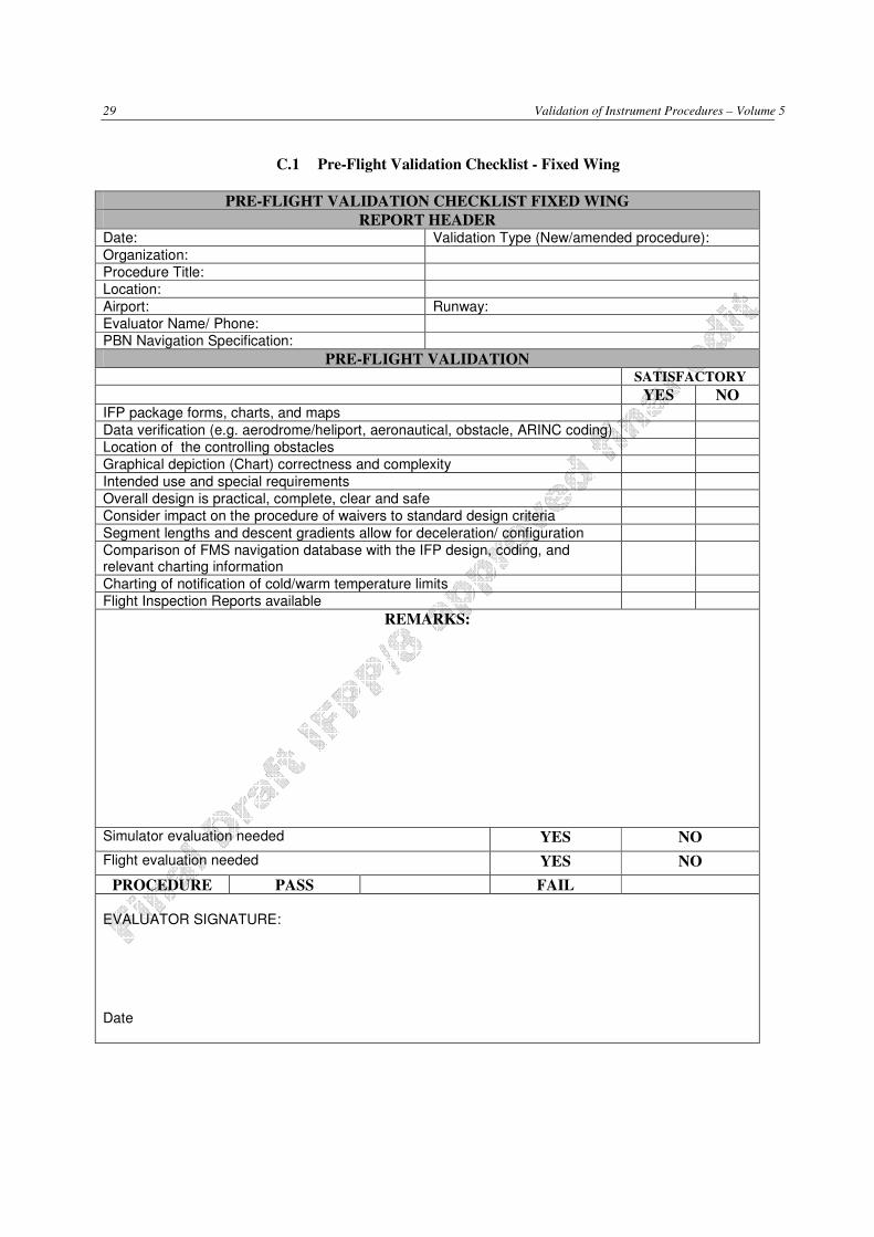
29 Validation of Instrument Procedures – Volume 5
C.1 Pre-Flight Validation Checklist - Fixed Wing
PRE-FLIGHT VALIDATION CHECKLIST FIXED WING
REPORT HEADER Date: Validation Type (New/amended procedure):
Organization:
Procedure Title:
Location:
Airport: Runway:
Evaluator Name/ Phone:
PBN Navigation Specification:
PRE-FLIGHT VALIDATION SATISFACTORY
YES NO IFP package forms, charts, and maps
Data verification (e.g. aerodrome/heliport, aeronautical, obstacle, ARINC coding)
Location of the controlling obstacles
Graphical depiction (Chart) correctness and complexity
Intended use and special requirements
Overall design is practical, complete, clear and safe
Consider impact on the procedure of waivers to standard design criteria
Segment lengths and descent gradients allow for deceleration/ configuration
Comparison of FMS navigation database with the IFP design, coding, and relevant charting information
Charting of notification of cold/warm temperature limits
Flight Inspection Reports available
REMARKS:
Simulator evaluation needed YES NO
Flight evaluation needed YES NO
PROCEDURE PASS FAIL EVALUATOR SIGNATURE: Date
Validation of Instrument Procedures – Volume 5 30
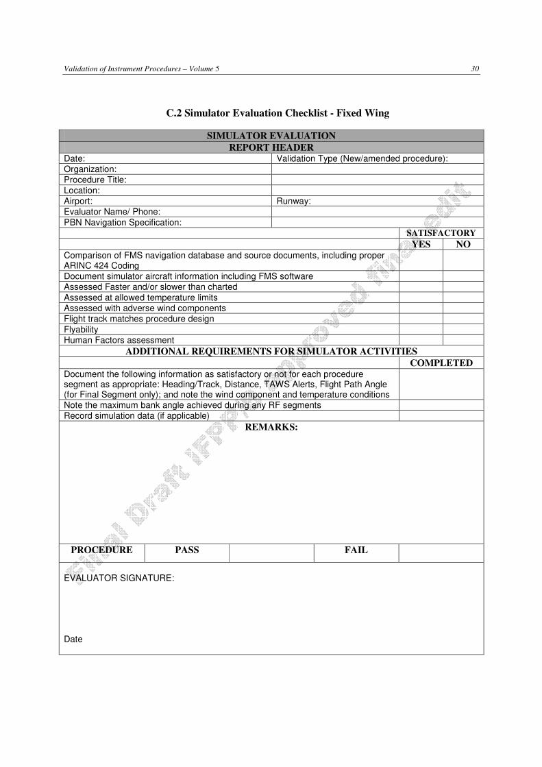
C.2 Simulator Evaluation Checklist - Fixed Wing
SIMULATOR EVALUATION
REPORT HEADER Date: Validation Type (New/amended procedure):
Organization:
Procedure Title:
Location:
Airport: Runway:
Evaluator Name/ Phone:
PBN Navigation Specification:
SATISFACTORY
YES NO Comparison of FMS navigation database and source documents, including proper ARINC 424 Coding
Document simulator aircraft information including FMS software
Assessed Faster and/or slower than charted
Assessed at allowed temperature limits
Assessed with adverse wind components
Flight track matches procedure design
Flyability
Human Factors assessment
ADDITIONAL REQUIREMENTS FOR SIMULATOR ACTIVITIES
COMPLETED Document the following information as satisfactory or not for each procedure segment as appropriate: Heading/Track, Distance, TAWS Alerts, Flight Path Angle (for Final Segment only); and note the wind component and temperature conditions
Note the maximum bank angle achieved during any RF segments
Record simulation data (if applicable)
REMARKS:
PROCEDURE PASS FAIL
EVALUATOR SIGNATURE: Date
31 Validation of Instrument Procedures – Volume 5
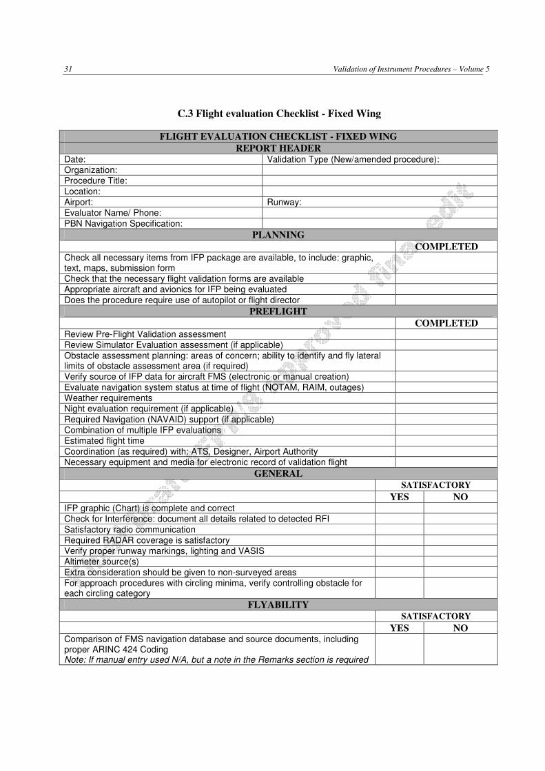
C.3 Flight evaluation Checklist - Fixed Wing
FLIGHT EVALUATION CHECKLIST - FIXED WING
REPORT HEADER Date: Validation Type (New/amended procedure):
Organization:
Procedure Title:
Location:
Airport: Runway:
Evaluator Name/ Phone:
PBN Navigation Specification:
PLANNING
COMPLETED Check all necessary items from IFP package are available, to include: graphic, text, maps, submission form
Check that the necessary flight validation forms are available
Appropriate aircraft and avionics for IFP being evaluated
Does the procedure require use of autopilot or flight director
PREFLIGHT
COMPLETED Review Pre-Flight Validation assessment
Review Simulator Evaluation assessment (if applicable)
Obstacle assessment planning: areas of concern; ability to identify and fly lateral limits of obstacle assessment area (if required)
Verify source of IFP data for aircraft FMS (electronic or manual creation)
Evaluate navigation system status at time of flight (NOTAM, RAIM, outages)
Weather requirements
Night evaluation requirement (if applicable)
Required Navigation (NAVAID) support (if applicable)
Combination of multiple IFP evaluations
Estimated flight time
Coordination (as required) with: ATS, Designer, Airport Authority
Necessary equipment and media for electronic record of validation flight
GENERAL
SATISFACTORY
YES NO IFP graphic (Chart) is complete and correct
Check for Interference: document all details related to detected RFI
Satisfactory radio communication
Required RADAR coverage is satisfactory
Verify proper runway markings, lighting and VASIS
Altimeter source(s)
Extra consideration should be given to non-surveyed areas
For approach procedures with circling minima, verify controlling obstacle for each circling category
FLYABILITY
SATISFACTORY
YES NO Comparison of FMS navigation database and source documents, including proper ARINC 424 Coding Note: If manual entry used N/A, but a note in the Remarks section is required

Validation of Instrument Procedures – Volume 5 32
to alert the approving authority of the procedure that a table top review of the coded procedure, or an operational assessment by a company pilot, should be completed prior to operational approval granted.
Human Factors and general workload satisfactory
Was there any loss of RAIM
Was there any loss of required RNP navigation performance (when RNP pertains)
Missed approach procedure
Descent/ Climb gradients
Use of autopilot satisfactory
Segment length, turns and bank angles, speed restrictions and deceleration allowance
TAWS
INSTRUMENT APPROACH PROCEDURE SATISFACTORY
YES NO Segment lengths, headings/ tracks, and waypoint locations match procedure design
Final segment vertical glide path angle (if applicable)
Threshold Crossing Height (LTP or FTP), if applicable
Course Alignment
Along Track Alignment
FAS Datablock
REMARKS:
PROCEDURE PASS FAIL
EVALUATOR SIGNATURE: Date

33 Validation of Instrument Procedures – Volume 5
C.4 Validation Report Checklist - Fixed Wing
VALIDATION REPORT CHECKLIST - FIXED WING
REPORT HEADER Date: Validation Type (New/amended procedure):
Organization:
Procedure Title:
Location:
Airport: Runway:
Evaluator Name/ Phone:
PBN Navigation Specification:
POST FLIGHT COMPLETED Evaluate collected data
Submit flight validation report with recorded electronic flight data for archive
Request NOTAM action (if appropriate)
Sign and submit the instrument flight procedure submission documentation
REMARKS:
PROCEDURE PASS FAIL
EVALUATOR SIGNATURE: Date
Validation of Instrument Procedures – Volume 5 34
Appendix D – VALIDATION TEMPLATES FOR HELICOPTERS
The following sample checklist and report templates contain minimum suggested data and information
required to be recorded during the Flight Validation Process of an RNAV IAP including SBAS. If certain
items are not applicable to the intended IAP, identify the boxes in the form by strikethrough or the term
“n/a”. Such forms must be signed.
States may develop their own version for other types of IFP as required.

35 Validation of Instrument Procedures – Volume 5
D.1 Pre-Flight Validation Checklist - Helicopters
PRE-FLIGHT VALIDATION CHECKLIST HELICOPTER
REPORT HEADER Date: Validation Type (New/amended procedure):
Organization:
Procedure Title:
Location:
Heliport: Heliport:
Evaluator Name/ Phone:
PBN Navigation Specification:
PRE-FLIGHT VALIDATION SATISFACTORY
YES NO IFP package forms, charts, and maps
Data verification (e.g. aerodrome/heliport, aeronautical, obstacle, ARINC coding)
Location of the controlling obstacles
Graphical depiction (Chart) correctness and complexity
Intended use and special requirements
Overall design is practical, complete, clear and safe
Consider impact on the procedure of deviations from to design criteria
Segment lengths and descent gradients allow for deceleration/configuration
Flight Inspection Reports available
REMARKS:
Simulator available/needed YES NO
Flight evaluation needed YES NO
PROCEDURE PASS FAIL
EVALUATOR SIGNATURE: Date
Validation of Instrument Procedures – Volume 5 36
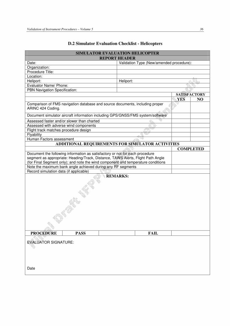
D.2 Simulator Evaluation Checklist - Helicopters
SIMULATOR EVALUATION HELICOPTER
REPORT HEADER Date: Validation Type (New/amended procedure):
Organization:
Procedure Title:
Location:
Heliport: Heliport:
Evaluator Name/ Phone:
PBN Navigation Specification:
SATISFACTORY
YES NO Comparison of FMS navigation database and source documents, including proper ARINC 424 Coding.
Document simulator aircraft information including GPS/GNSS/FMS system/software
Assessed faster and/or slower than charted
Assessed with adverse wind components
Flight track matches procedure design
Flyability
Human Factors assessment
ADDITIONAL REQUIREMENTS FOR SIMULATOR ACTIVITIES
COMPLETED Document the following information as satisfactory or not for each procedure segment as appropriate: Heading/Track, Distance, TAWS Alerts, Flight Path Angle (for Final Segment only); and note the wind component and temperature conditions
Note the maximum bank angle achieved during any RF segments
Record simulation data (if applicable)
REMARKS:
PROCEDURE PASS FAIL
EVALUATOR SIGNATURE: Date

37 Validation of Instrument Procedures – Volume 5
D.3 Flight Evaluation Checklist - Helicopters
FLIGHT EVALUATION CHECKLIST - HELICOPTER
REPORT HEADER Date: Validation Type (New/amended procedure):
Organization:
Procedure Title:
Location:
Heliport: Heliport:
Evaluator Name/ Phone:
PBN Navigation Specification:
PLANNING
COMPLETED Check all necessary items from IFP package are available, to include: graphic, text, maps, submission form
Check that the necessary flight validation forms are available
Appropriate aircraft and avionics for IFP being evaluated
Does the procedure require use of autopilot or flight director
PREFLIGHT
COMPLETED Review Pre-Flight Validation assessment
Review Simulator Evaluation assessment (if applicable)
Obstacle assessment planning: areas of concern; ability to identify and fly lateral limits of obstacle assessment area (if required)
Verify source of IFP data for aircraft GPS/GNSS/FMS (electronic or manual creation)
Evaluate navigation system status at time of flight (NOTAM, RAIM, outages)
Weather requirements
Night evaluation requirement (if applicable)
Required Navigation (NAVAID) support (if applicable)
Combination of multiple IFP evaluations
Estimated flight time
Coordination (as required) with: ATS, Designer, Relevant Authority
Necessary equipment and media for electronic record of validation flight
GENERAL
SATISFACTORY
YES NO IFP graphic (Chart) is complete and correct
Check for Interference: document all details related to detected RFI
Satisfactory radio communication
Required RADAR coverage is satisfactory (if RADAR required)
Verify proper heliport markings, lighting and VASIS (if installed)
Altimeter source(s)
OBSTACLE ASSESSMENT
SATISFACTORY
YES NO Verified controlling obstacle in each segment (including as appropriate: VFR, Direct Visual Segment, or Manoeuvring visual segment area/s, missed approach); if any obstacles are missing or any new obstacles are observed, record the lat/long and elevation of obstacles observed.

Validation of Instrument Procedures – Volume 5 38
Where necessary, flown at lateral limits of the obstacle assessment area; most appropriate for procedures designed in challenging terrain, or when there are questionable obstacles. Note: Extra consideration should be given to non-surveyed areas
FLYABILITY
SATISFACTORY
YES NO
Comparison of GPS/GNSS/FMS navigation database and source documents, including proper ARINC 424 Coding. Note: If manual entry used N/A, but a note in the Remarks section is required to alert the approving authority of the procedure that a table top review of the coded procedure, or an operational assessment by a company pilot, should be completed prior to operational approval granted.
Human Factors and general workload satisfactory
Was there any RAIM loss
Was there any loss of required RNP navigation performance (when RNP pertains)
Missed approach procedure
Descent/ Climb gradients
Use of autopilot satisfactory
Segment length, turns and bank angles, speed restrictions and deceleration allowance
TAWS
INSTRUMENT APPROACH PROCEDURE
SATISFACTORY YES NO
Segment lengths, headings/ tracks, and waypoint locations match procedure design
Final segment vertical glide path angle (if applicable)
Heliport Crossing Height (HRP), if applicable
Course Alignment
Along Track Alignment
FAS Datablock (for SBAS APV procedures)
REMARKS:
PROCEDURE PASS FAIL
EVALUATOR SIGNATURE: Date
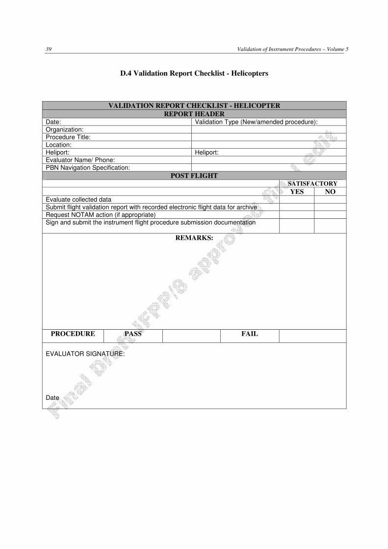
39 Validation of Instrument Procedures – Volume 5
D.4 Validation Report Checklist - Helicopters
VALIDATION REPORT CHECKLIST - HELICOPTER
REPORT HEADER Date: Validation Type (New/amended procedure):
Organization:
Procedure Title:
Location:
Heliport: Heliport:
Evaluator Name/ Phone:
PBN Navigation Specification:
POST FLIGHT SATISFACTORY YES NO Evaluate collected data
Submit flight validation report with recorded electronic flight data for archive
Request NOTAM action (if appropriate)
Sign and submit the instrument flight procedure submission documentation
REMARKS:
PROCEDURE PASS FAIL
EVALUATOR SIGNATURE: Date
Related Documents