arXiv:1202.3894v1 [astro-ph.IM] 17 Feb 2012 The Positioning System of the ANTARES Neutrino Telescope S. Adri´ an-Mart´ ınez a , M. Ageron c , J.A. Aguilar b , I. Al Samarai c , A. Albert d , M. Andr´ e e , M. Anghinolfi f , G. Anton g , S. Anvar h , M. Ardid a , A.C. Assis Jesus i , T. Astraatmadja i,1 , J-J. Aubert c , B. Baret j , S. Basa k , V. Bertin c , S. Biagi ℓ,m , A. Bigi n , C. Bigongiari b , C. Bogazzi i , M. Bou-Cabo a , B. Bouhou j , M.C. Bouwhuis i , J. Brunner c,2 , J. Busto c , F. Camarena a , A. Capone o,p , C. Cˆ arloganu q , G. Carminati ℓ,m,3 , J. Carr c , S. Cecchini ℓ , Z. Charif c , Ph. Charvis r , T. Chiarusi ℓ , M. Circella s , R. Coniglione u , H. Costantini f ,c , P. Coyle c , C. Curtil c , M.P. Decowski i , I. Dekeyser t , A. Deschamps r , C. Distefano u , C. Donzaud j,v , D. Dornic b,c , Q. Dorosti w , D. Drouhin d , T. Eberl g , U. Emanuele b , A. Enzenh¨ofer g , J-P. Ernenwein c , S. Escoffier c , P. Fermani o,p , M. Ferri a , V. Flaminio n,x , F. Folger g , U. Fritsch g , J-L. Fuda t ,S.Galat`a c , P. Gay q , G. Giacomelli ℓ,m , V. Giordano u , J.P. G´ omez-Gonz´alez b , K. Graf g , G. Guillard q , G. Halladjian c , G. Hallewell c , H. van Haren y , J. Hartman i , A.J. Heijboer i , Y. Hello r , J.J. Hern´ andez-Rey b , B. Herold g , J.H¨oßl g , C.C. Hsu i , M. de Jong i,1 , M. Kadler z , O. Kalekin g , A. Kappes g , U. Katz g , O. Kavatsyuk w , P. Keller c , P. Kooijman i,aa,ab , C. Kopper i,g , A. Kouchner j , I. Kreykenbohm z , V. Kulikovskiy ac,f , R. Lahmann g , P. Lamare h , G. Larosa a , D. Lattuada u , D. Lef` evre t , A. Le Van Suu c , G. Lim i,ab , D. Lo Presti ad,ae , H. Loehner w , S. Loucatos af , S. Mangano b , M. Marcelin k , A. Margiotta ℓ,m , J.A. Mart´ ınez-Mora a , A. Meli g , T. Montaruli s,ag , L. Moscoso j,af ,4 , H. Motz g , M. Neff g , E. Nezri k , V. Niess q , D. Palioselitis i , G.E. P˘ av˘ ala¸ s ah , K. Payet af , P. Payre c,4 , J. Petrovic i , P. Piattelli u , N. Picot-Clemente c , V. Popa ah , T. Pradier ai , E. Presani i , C. Racca d , D. Real b , C. Reed i , Preprint submitted to Elsevier 20 February 2012

Welcome message from author
This document is posted to help you gain knowledge. Please leave a comment to let me know what you think about it! Share it to your friends and learn new things together.
Transcript

arX
iv:1
202.
3894
v1 [
astr
o-ph
.IM
] 1
7 Fe
b 20
12
The Positioning System of the ANTARES
Neutrino Telescope
S. Adrian-Martınez a, M. Ageron c, J.A. Aguilar b,
I. Al Samarai c, A. Albert d, M. Andre e, M. Anghinolfi f,G. Anton g, S. Anvar h, M. Ardid a, A.C. Assis Jesus i,
T. Astraatmadja i,1, J-J. Aubert c, B. Baret j, S. Basa k,V. Bertin c, S. Biagi ℓ,m, A. Bigi n, C. Bigongiari b, C. Bogazzi i,
M. Bou-Cabo a, B. Bouhou j, M.C. Bouwhuis i, J. Brunner c,2,J. Busto c, F. Camarena a, A. Capone o,p, C. Carloganu q,
G. Carminati ℓ,m,3, J. Carr c, S. Cecchini ℓ, Z. Charif c,Ph. Charvis r, T. Chiarusi ℓ, M. Circella s, R. Coniglione u,H. Costantini f,c, P. Coyle c, C. Curtil c, M.P. Decowski i,
I. Dekeyser t, A. Deschamps r, C. Distefano u, C. Donzaud j,v,D. Dornic b,c, Q. Dorosti w, D. Drouhin d, T. Eberl g,
U. Emanuele b, A. Enzenhofer g, J-P. Ernenwein c, S. Escoffier c,P. Fermani o,p, M. Ferri a, V. Flaminio n,x, F. Folger g,
U. Fritsch g, J-L. Fuda t, S. Galata c, P. Gay q, G. Giacomelli ℓ,m,V. Giordano u, J.P. Gomez-Gonzalez b, K. Graf g, G. Guillard q,G. Halladjian c, G. Hallewell c, H. van Haren y, J. Hartman i,
A.J. Heijboer i, Y. Hello r, J.J. Hernandez-Rey b, B. Herold g,J. Hoßl g, C.C. Hsu i, M. de Jong i,1, M. Kadler z, O. Kalekin g,
A. Kappes g, U. Katz g, O. Kavatsyuk w, P. Keller c,P. Kooijman i,aa,ab, C. Kopper i,g, A. Kouchner j,
I. Kreykenbohm z, V. Kulikovskiy ac,f, R. Lahmann g,P. Lamare h, G. Larosa a, D. Lattuada u, D. Lefevre t,
A. Le Van Suu c, G. Lim i,ab, D. Lo Presti ad,ae, H. Loehner w,S. Loucatos af, S. Mangano b, M. Marcelin k, A. Margiotta ℓ,m,
J.A. Martınez-Mora a, A. Meli g, T. Montaruli s,ag,
L. Moscoso j,af,4, H. Motz g, M. Neff g, E. Nezri k, V. Niess q,D. Palioselitis i, G.E. Pavalas ah, K. Payet af, P. Payre c,4,
J. Petrovic i, P. Piattelli u, N. Picot-Clemente c, V. Popa ah,T. Pradier ai, E. Presani i, C. Racca d, D. Real b, C. Reed i,
Preprint submitted to Elsevier 20 February 2012

G. Riccobene u, C. Richardt g, R. Richter g, C. Riviere c,A. Robert t, K. Roensch g, A. Rostovtsev aj, J. Ruiz-Rivas b,
M. Rujoiu ah, G.V. Russo ad,ae, F. Salesa b, D.F.E. Samtleben i,F. Schock g, J-P. Schuller af, F. Schussler af, T. Seitz g,
R. Shanidze g, F. Simeone o,p, A. Spies g, M. Spurio ℓ,m,J.J.M. Steijger i, Th. Stolarczyk af, A. Sanchez-Losa b,
M. Taiuti f,ak, C. Tamburini t, S. Toscano b, B. Vallage af,V. Van Elewyck j, G. Vannoni af, M. Vecchi c, P. Vernin af,
S. Wagner g, G. Wijnker i, J. Wilms z, E. de Wolf i,ab, H. Yepes b,D. Zaborov aj, J.D. Zornoza b, J. Zuniga b
aInstitut d’Investigacio per a la Gestio Integrada de les Zones Costaneres (IGIC) - UniversitatPolitecnica de Valencia. C/ Paranimf 1 , 46730 Gandia, Spain.
bIFIC - Instituto de Fısica Corpuscular, Edificios Investigacion de Paterna, CSIC - Universitat deValencia, Apdo. de Correos 22085, 46071 Valencia, Spain
cCPPM, Aix-Marseille Universite, CNRS/IN2P3, Marseille, France
dGRPHE - Institut universitaire de technologie de Colmar, 34 rue du Grillenbreit BP 50568 - 68008Colmar, France
eTechnical University of Catalonia, Laboratory of Applied Bioacoustics, Rambla Exposicio,08800Vilanova i la Geltru,Barcelona, Spain
f INFN - Sezione di Genova, Via Dodecaneso 33, 16146 Genova, Italy
gFriedrich-Alexander-Universitat Erlangen-Nurnberg, Erlangen Centre for Astroparticle Physics,Erwin-Rommel-Str. 1, 91058 Erlangen, Germany
hDirection des Sciences de la Matiere - Institut de recherche sur les lois fondamentales de l’Univers -Service d’Electronique des Detecteurs et d’Informatique, CEA Saclay, 91191 Gif-sur-Yvette Cedex,
France
iNikhef, Science Park, Amsterdam, The Netherlands
jAPC - Laboratoire AstroParticule et Cosmologie, UMR 7164 (CNRS, Universite Paris 7 Diderot, CEA,Observatoire de Paris) 10, rue Alice Domon et Leonie Duquet 75205 Paris Cedex 13, France
kLAM - Laboratoire d’Astrophysique de Marseille, Pole de l’Etoile Site de Chateau-Gombert, rueFrederic Joliot-Curie 38, 13388 Marseille Cedex 13, France
ℓINFN - Sezione di Bologna, Viale Berti-Pichat 6/2, 40127 Bologna, Italy
mDipartimento di Fisica dell’Universita, Viale Berti Pichat 6/2, 40127 Bologna, Italy
nINFN - Sezione di Pisa, Largo B. Pontecorvo 3, 56127 Pisa, Italy
oINFN -Sezione di Roma, P.le Aldo Moro 2, 00185 Roma, Italy
pDipartimento di Fisica dell’Universita La Sapienza, P.le Aldo Moro 2, 00185 Roma, Italy
qClermont Universite, Universite Blaise Pascal, CNRS/IN2P3, Laboratoire de Physique Corpusculaire,BP 10448, 63000 Clermont-Ferrand, France
rGeoazur - Universite de Nice Sophia-Antipolis, CNRS/INSU, IRD, Observatoire de la Cote d’Azur andUniversite Pierre et Marie Curie, BP 48, 06235 Villefranche-sur-mer, France
sINFN - Sezione di Bari, Via E. Orabona 4, 70126 Bari, Italy
tCOM - Centre d’Oceanologie de Marseille, CNRS/INSU et Universite de la Mediterranee, 163 Avenuede Luminy, Case 901, 13288 Marseille Cedex 9, France
uINFN - Laboratori Nazionali del Sud (LNS), Via S. Sofia 62, 95123 Catania, Italy
vUniv Paris-Sud , 91405 Orsay Cedex, France
2
wKernfysisch Versneller Instituut (KVI), University of Groningen, Zernikelaan 25, 9747 AA Groningen,The Netherlands
xDipartimento di Fisica dell’Universita, Largo B. Pontecorvo 3, 56127 Pisa, Italy
yRoyal Netherlands Institute for Sea Research (NIOZ), Landsdiep 4,1797 SZ ’t Horntje (Texel), TheNetherlands
zDr. Remeis-Sternwarte and ECAP, Universitat Erlangen-Nurnberg, Sternwartstr. 7, 96049 Bamberg,Germany
aaUniversiteit Utrecht, Faculteit Betawetenschappen, Princetonplein 5, 3584 CC Utrecht, TheNetherlands
abUniversiteit van Amsterdam, Instituut voor Hoge-Energie Fysika, Science Park 105, 1098 XGAmsterdam, The Netherlands
acMoscow State University,Skobeltsyn Institute of Nuclear Physics,Leninskie gory, 119991 Moscow,Russia
adINFN - Sezione di Catania, Viale Andrea Doria 6, 95125 Catania, Italy
aeDipartimento di Fisica ed Astronomia dell’Universita, Viale Andrea Doria 6, 95125 Catania, Italy
afDirection des Sciences de la Matiere - Institut de recherche sur les lois fondamentales de l’Univers -Service de Physique des Particules, CEA Saclay, 91191 Gif-sur-Yvette Cedex, France
ag Departement de physique nucleaire et corpusculaire, Universite de Geneve, 1211, Switzerland
ahInstitute for Space Sciences, R-77125 Bucharest, Magurele, Romania
aiIPHC-Institut Pluridisciplinaire Hubert Curien - Universite de Strasbourg et CNRS/IN2P3 23 rue duLoess, BP 28, 67037 Strasbourg Cedex 2, France
ajITEP - Institute for Theoretical and Experimental Physics, B. Cheremushkinskaya 25, 117218 Moscow,Russia
akDipartimento di Fisica dell’Universita, Via Dodecaneso 33, 16146 Genova, Italy
Abstract
The ANTARES neutrino telescope, located 40 km off the coast of Toulon in theMediterranean Sea at a mooring depth of about 2475m, consists of twelve detectionlines equipped typically with 25 storeys. Every storey carries three optical mod-ules that detect Cherenkov light induced by charged secondary particles (typicallymuons) coming from neutrino interactions. As these lines are flexible structuresfixed to the sea bed and held taut by a buoy, sea currents cause the lines to moveand the storeys to rotate. The knowledge of the position of the optical moduleswith a precision better than 10 cm is essential for a good reconstruction of particletracks. In this paper the ANTARES positioning system is described. It consists ofan acoustic positioning system, for distance triangulation, and a compass-tiltmetersystem, for the measurement of the orientation and inclination of the storeys. Nec-essary corrections are discussed and the results of the detector alignment procedureare described.Keywords: ANTARES neutrino telescope, detector alignment, acoustic positioning,calibration.
3
1 Introduction
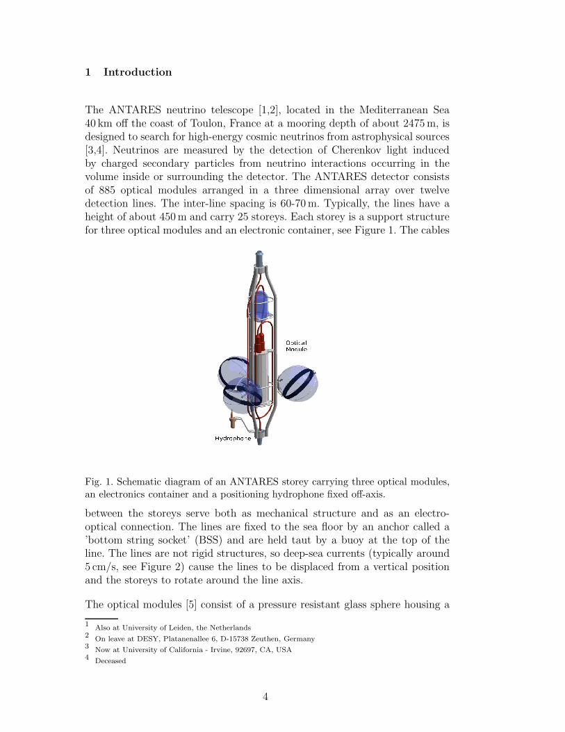
The ANTARES neutrino telescope [1,2], located in the Mediterranean Sea40 km off the coast of Toulon, France at a mooring depth of about 2475m, isdesigned to search for high-energy cosmic neutrinos from astrophysical sources[3,4]. Neutrinos are measured by the detection of Cherenkov light inducedby charged secondary particles from neutrino interactions occurring in thevolume inside or surrounding the detector. The ANTARES detector consistsof 885 optical modules arranged in a three dimensional array over twelvedetection lines. The inter-line spacing is 60-70m. Typically, the lines have aheight of about 450m and carry 25 storeys. Each storey is a support structurefor three optical modules and an electronic container, see Figure 1. The cables
Fig. 1. Schematic diagram of an ANTARES storey carrying three optical modules,an electronics container and a positioning hydrophone fixed off-axis.
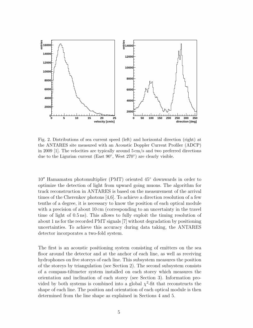
between the storeys serve both as mechanical structure and as an electro-optical connection. The lines are fixed to the sea floor by an anchor called a’bottom string socket’ (BSS) and are held taut by a buoy at the top of theline. The lines are not rigid structures, so deep-sea currents (typically around5 cm/s, see Figure 2) cause the lines to be displaced from a vertical positionand the storeys to rotate around the line axis.
The optical modules [5] consist of a pressure resistant glass sphere housing a
1Also at University of Leiden, the Netherlands
2On leave at DESY, Platanenallee 6, D-15738 Zeuthen, Germany
3Now at University of California - Irvine, 92697, CA, USA
4Deceased
4
velocity [cm/s]0 5 10 15 20 25
entri
es
0
2000
4000
6000
8000
10000
12000
14000
16000
direction [deg]0 50 100 150 200 250 300 350
entri
es
2000
4000
6000
8000
10000
12000
14000
Fig. 2. Distributions of sea current speed (left) and horizontal direction (right) atthe ANTARES site measured with an Acoustic Doppler Current Profiler (ADCP)in 2009 [1]. The velocities are typically around 5 cm/s and two preferred directionsdue to the Ligurian current (East 90◦, West 270◦) are clearly visible.
10′′ Hamamatsu photomultiplier (PMT) oriented 45◦ downwards in order tooptimize the detection of light from upward going muons. The algorithm fortrack reconstruction in ANTARES is based on the measurement of the arrivaltimes of the Cherenkov photons [4,6]. To achieve a direction resolution of a fewtenths of a degree, it is necessary to know the position of each optical modulewith a precision of about 10 cm (corresponding to an uncertainty in the traveltime of light of 0.5 ns). This allows to fully exploit the timing resolution ofabout 1 ns for the recorded PMT signals [7] without degradation by positioninguncertainties. To achieve this accuracy during data taking, the ANTARESdetector incorporates a two-fold system.
The first is an acoustic positioning system consisting of emitters on the seafloor around the detector and at the anchor of each line, as well as receivinghydrophones on five storeys of each line. This subsystem measures the positionof the storeys by triangulation (see Section 2). The second subsystem consistsof a compass-tiltmeter system installed on each storey which measures theorientation and inclination of each storey (see Section 3). Information pro-vided by both systems is combined into a global χ2-fit that reconstructs theshape of each line. The position and orientation of each optical module is thendetermined from the line shape as explained in Sections 4 and 5.
5
2 The Acoustic Positioning System
The acoustic positioning system of the ANTARES experiment is composed oftwo subsystems. The low frequency long baseline positioning system (LFLBL)is used to connect the local frame of the detector to the geodetic refer-ence frame. This allows the absolute position and orientation of the detec-tor to be determined. The high frequency long baseline positioning system(HFLBL) serves to measure the relative positions of the different elements ofthe ANTARES detector within the local detector frame with high accuracy.
2.1 The Low Frequency Long Baseline Positioning System
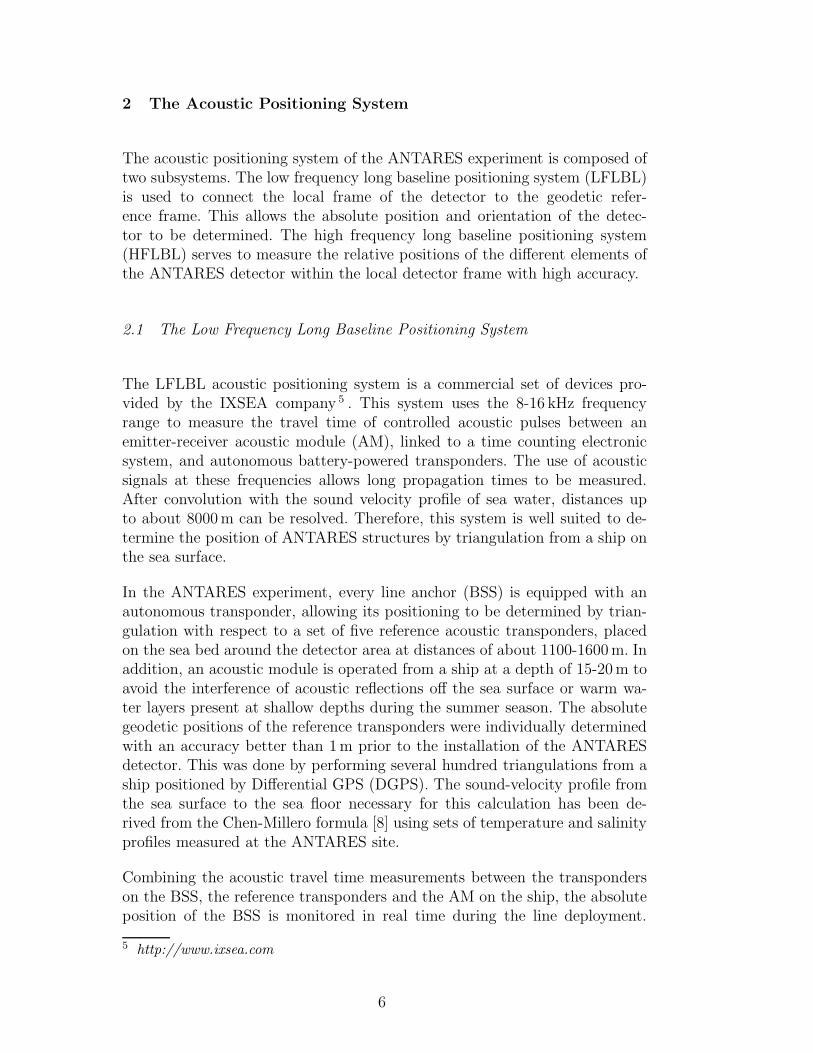
The LFLBL acoustic positioning system is a commercial set of devices pro-vided by the IXSEA company 5 . This system uses the 8-16 kHz frequencyrange to measure the travel time of controlled acoustic pulses between anemitter-receiver acoustic module (AM), linked to a time counting electronicsystem, and autonomous battery-powered transponders. The use of acousticsignals at these frequencies allows long propagation times to be measured.After convolution with the sound velocity profile of sea water, distances upto about 8000m can be resolved. Therefore, this system is well suited to de-termine the position of ANTARES structures by triangulation from a ship onthe sea surface.
In the ANTARES experiment, every line anchor (BSS) is equipped with anautonomous transponder, allowing its positioning to be determined by trian-gulation with respect to a set of five reference acoustic transponders, placedon the sea bed around the detector area at distances of about 1100-1600m. Inaddition, an acoustic module is operated from a ship at a depth of 15-20m toavoid the interference of acoustic reflections off the sea surface or warm wa-ter layers present at shallow depths during the summer season. The absolutegeodetic positions of the reference transponders were individually determinedwith an accuracy better than 1m prior to the installation of the ANTARESdetector. This was done by performing several hundred triangulations from aship positioned by Differential GPS (DGPS). The sound-velocity profile fromthe sea surface to the sea floor necessary for this calculation has been de-rived from the Chen-Millero formula [8] using sets of temperature and salinityprofiles measured at the ANTARES site.
Combining the acoustic travel time measurements between the transponderson the BSS, the reference transponders and the AM on the ship, the absoluteposition of the BSS is monitored in real time during the line deployment.
5 http://www.ixsea.com
6
The position is determined with an accuracy of a few metres and the finalanchoring position of the BSS with an accuracy better than 1m after statisticalaveraging.
In order to determine the absolute orientation of the detector, accurate mea-surements of the BSS positions are vital. Therefore, the relative positionsof the line anchors are constrained using all distances between pairs of highfrequency positioning transducers obtained from the HFLBL system (accu-racy about 3 cm, see Section 2.2). Since the high frequency transponders aremounted about one metre off-axis with respect to the line – whereas theLFLBL transponder is located close to the line axis – the orientation of theBSS has to be considered. The latter is determined with an accuracy of about5◦ using the compass of a submarine vehicle during an undersea line connec-tion. In addition, the relative depth of the sea bed at the position of eachBSS is measured by a pressure sensor on the submarine with a precision ofabout 10 cm. Using the HFLBL triangulation data under the assumption thatthe line remains almost vertical for small speeds of the sea current (smallerthan 2 cm/s) and combining with the supplementary data described above,the determination of the BSS depth is substantially improved.
The absolute orientation of the neutrino telescope with respect to the sky isobtained using both the absolute positions of the different line anchors andthe BSS to BSS relative positions. An estimate of the accuracy of the absolutepointing of the ANTARES telescope was obtained by Monte Carlo techniquestaking into account the accuracy of the individual BSS positions, BSS toBSS distances and the uncertainty of the sound velocity [9]. The resultinguncertainty for the absolute orientation was found to be less than 0.13 ◦ in thehorizontal and less than 0.06 ◦ in the vertical. This well matches the resolutionof about 0.2 ◦ aimed at for high energy muon track reconstruction.
2.2 The High Frequency Long Baseline Positioning System
The HFLBL acoustic positioning system of ANTARES was developed andconstructed by the company GENISEA/ECA 6 . It is used to determine theposition of the detector elements relative to the BSS positions with high pre-cision. The positioning method is based on a measurement of travel times ofacoustic sinusoidal pulses (40–60 kHz) between acoustic transceivers fixed atthe line anchors and receiving hydrophones on the detector lines. These acous-tic distance measurements are then combined to obtain the positions of thehydrophones by triangulation. For the frequencies used, the attenuation lengthin sea water of 700-1000m [10] is sufficiently long for acoustic measurementsover the ANTARES dimensions.
6 Formerly GENISEA now ECA, http://www.eca.fr
7
In addition to the battery powered transponder of the LFLBL, each ANTARESdetector line is equipped with a transceiver fixed on a rod at the BSS. It isoperated as receiver and emitter (RxTx module). Five storeys of each line(storeys 1, 8, 14, 20 and 25, counted from below) carry receiving hydrophones(Rx modules) to detect the signals of the emitters. The distances between thehydrophones are smaller in the upper part of the line where the displacementfrom the nominal position is larger.
The RxTx modules are composed of one transceiver and six electronic boardslocated in the String Control Module (SCM) of each BSS. Their purpose is theemission of acoustic signals (to be detected by the Rx modules), triggered byan external synchronisation signal (Master Clock), the detection of the signalsof other RxTx modules, the stamping of the detection time with respect tothe Master Clock and the transmission of the timestamps and amplitudesto the shore station. The Rx modules are composed of one hydrophone andthree electronic cards in the Local Control Module (LCM) of the respectivestorey. They fulfill the same tasks as the RxTx modules except the emissionof acoustic signals.
The positioning of the ANTARES detector is done by successively sendingacoustic wavepackets (typical duration 2ms) from each RxTx module at dif-ferent frequencies to identify unambiguously the emitting module. The acous-tic emission is organized in a periodic succession of cycles (every two minutes,programmable from onshore). One cycle consists of the emissions of all RxTxmodules at their respective frequencies between 44.522 kHz and 60.235 kHz ina predefined sequence. Following the emission of a specific RxTx module allother RxTx and Rx modules are put into reception mode, searching for theemitted frequency with a band-pass filter. Once the modules detect acous-tic signals at the given frequency above a predefined threshold they providethe detection time together with the measured amplitude of the signal. Thethreshold as well as the amplification gain of every receiving module can be setindividually from shore. This allows to compensate the different attenuationof the emitted signals caused by different receiver-transmitter distances. Forthe RxTx modules, the emission frequency, level, duration and the delay be-tween emissions can be adjusted. A schematic of the HFLBL system is shownin Figure 3.
2.3 Determination of Distances and Positions
The relative position of each element of the acoustic positioning system can beevaluated by analysing the data after corrections and cleaning steps. First acorrection has to be applied to all measurements performed by a single sensorin order to compensate for the propagation delays, up to 4µs, of the clock
8
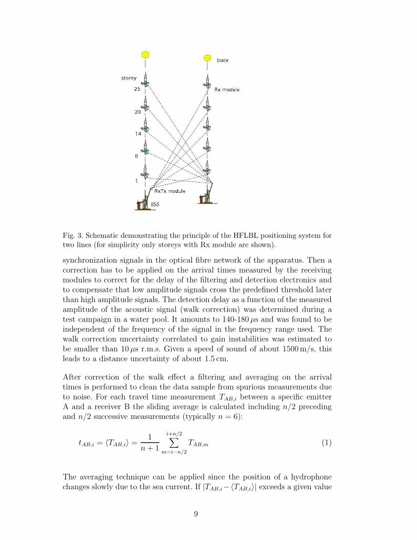
Fig. 3. Schematic demonstrating the principle of the HFLBL positioning system fortwo lines (for simplicity only storeys with Rx module are shown).
synchronization signals in the optical fibre network of the apparatus. Then acorrection has to be applied on the arrival times measured by the receivingmodules to correct for the delay of the filtering and detection electronics andto compensate that low amplitude signals cross the predefined threshold laterthan high amplitude signals. The detection delay as a function of the measuredamplitude of the acoustic signal (walk correction) was determined during atest campaign in a water pool. It amounts to 140-180µs and was found to beindependent of the frequency of the signal in the frequency range used. Thewalk correction uncertainty correlated to gain instabilities was estimated tobe smaller than 10µs r.m.s. Given a speed of sound of about 1500m/s, thisleads to a distance uncertainty of about 1.5 cm.
After correction of the walk effect a filtering and averaging on the arrivaltimes is performed to clean the data sample from spurious measurements dueto noise. For each travel time measurement TAB,i between a specific emitterA and a receiver B the sliding average is calculated including n/2 precedingand n/2 successive measurements (typically n = 6):
tAB,i = 〈TAB,i〉 =1
n+ 1
i+n/2∑
m=i−n/2
TAB,m (1)
The averaging technique can be applied since the position of a hydrophonechanges slowly due to the sea current. If |TAB,i−〈TAB,i〉| exceeds a given value
9
the data point i is judged as spurious and removed from the data sample.This procedure is repeated several times on the reduced sample with tightercuts, typically at 160µs, 80µs and 40µs, to reject a maximum of spuriousdetections without removing correct measurements.
The distance between the devices A and B can be calculated from the filteredtravel times tAB,i knowing the speed of sound in sea water. As the speed ofsound is not constant 7 the travel time is defined as the integral over the paths from A to B divided by the local sound velocity c(s):
tAB,i =
B∫
A
ds
c(s)(2)
The ANTARES detector includes several sound velocimeters that determine,locally, the sound speed in water by measuring the travel time of an acousticpulse over a distance of 20 cm. At the depth of the ANTARES neutrino tele-scope the speed of sound changes only with pressure i.e. with depth z (z-axischosen as vertically upward):
c(z) = c(z0)− kc(z − z0) (3)
where kc = 1.710 cms
1mderived from [8] for the Mediterranean Sea and z0 is the
depth of a sound velocimeter used to measure the speed of sound. The soundin deep-sea water does not propagate along a straight line, its trajectory isslightly bent. The bending radius of about 80 km [11] is more than 100 timeslarger than distances that have to be measured: for this reason the soundtravel path is approximated as straight and the distances between acousticmodules are calculated as
dAB,i = tAB,i
[
c(z0)− kc
(
zA + zB2
− z0
)]
(4)
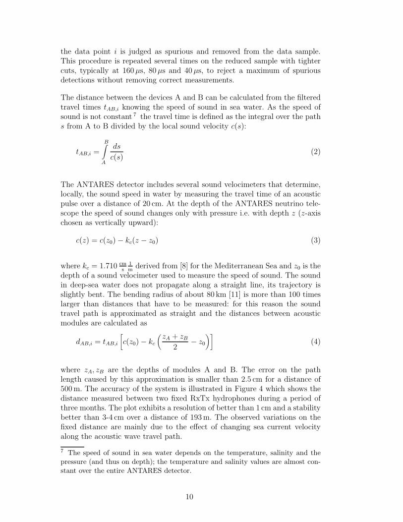
where zA, zB are the depths of modules A and B. The error on the pathlength caused by this approximation is smaller than 2.5 cm for a distance of500m. The accuracy of the system is illustrated in Figure 4 which shows thedistance measured between two fixed RxTx hydrophones during a period ofthree months. The plot exhibits a resolution of better than 1 cm and a stabilitybetter than 3-4 cm over a distance of 193m. The observed variations on thefixed distance are mainly due to the effect of changing sea current velocityalong the acoustic wave travel path.
7 The speed of sound in sea water depends on the temperature, salinity and thepressure (and thus on depth); the temperature and salinity values are almost con-stant over the entire ANTARES detector.
10
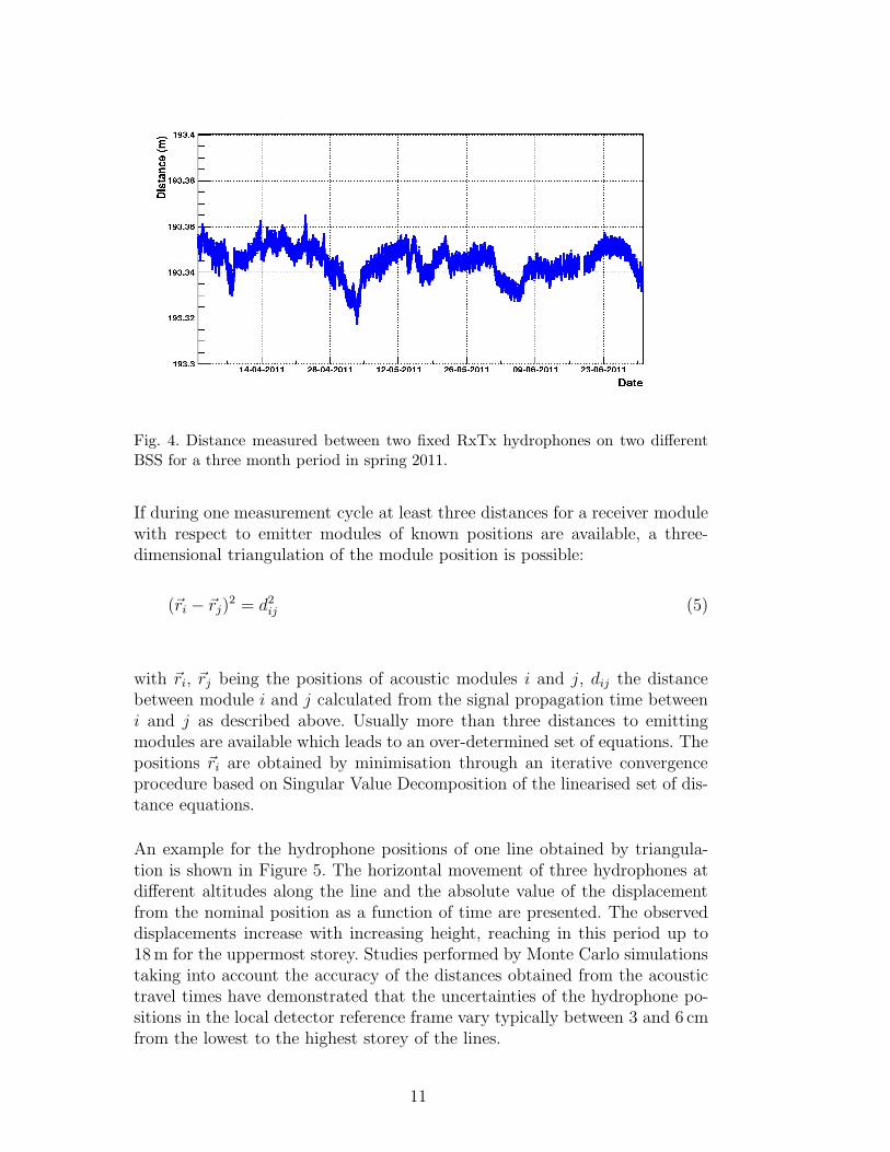
Fig. 4. Distance measured between two fixed RxTx hydrophones on two differentBSS for a three month period in spring 2011.
If during one measurement cycle at least three distances for a receiver modulewith respect to emitter modules of known positions are available, a three-dimensional triangulation of the module position is possible:
(~ri − ~rj)2 = d2ij (5)
with ~ri, ~rj being the positions of acoustic modules i and j, dij the distancebetween module i and j calculated from the signal propagation time betweeni and j as described above. Usually more than three distances to emittingmodules are available which leads to an over-determined set of equations. Thepositions ~ri are obtained by minimisation through an iterative convergenceprocedure based on Singular Value Decomposition of the linearised set of dis-tance equations.
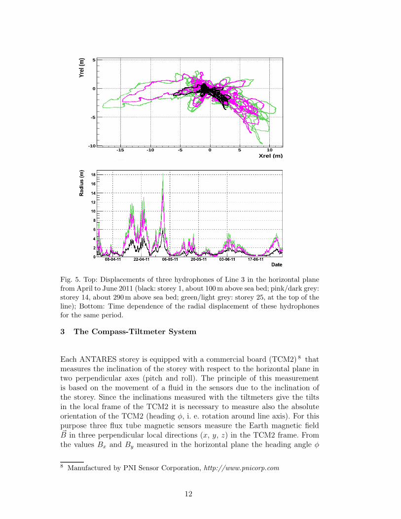
An example for the hydrophone positions of one line obtained by triangula-tion is shown in Figure 5. The horizontal movement of three hydrophones atdifferent altitudes along the line and the absolute value of the displacementfrom the nominal position as a function of time are presented. The observeddisplacements increase with increasing height, reaching in this period up to18m for the uppermost storey. Studies performed by Monte Carlo simulationstaking into account the accuracy of the distances obtained from the acoustictravel times have demonstrated that the uncertainties of the hydrophone po-sitions in the local detector reference frame vary typically between 3 and 6 cmfrom the lowest to the highest storey of the lines.
11
Xrel (m)-15 -10 -5 0 5 10
Yrel
(m)
-10
-5
0
5
Fig. 5. Top: Displacements of three hydrophones of Line 3 in the horizontal planefrom April to June 2011 (black: storey 1, about 100m above sea bed; pink/dark grey:storey 14, about 290m above sea bed; green/light grey: storey 25, at the top of theline); Bottom: Time dependence of the radial displacement of these hydrophonesfor the same period.
3 The Compass-Tiltmeter System
Each ANTARES storey is equipped with a commercial board (TCM2) 8 thatmeasures the inclination of the storey with respect to the horizontal plane intwo perpendicular axes (pitch and roll). The principle of this measurementis based on the movement of a fluid in the sensors due to the inclination ofthe storey. Since the inclinations measured with the tiltmeters give the tiltsin the local frame of the TCM2 it is necessary to measure also the absoluteorientation of the TCM2 (heading φ, i. e. rotation around line axis). For thispurpose three flux tube magnetic sensors measure the Earth magnetic field~B in three perpendicular local directions (x, y, z) in the TCM2 frame. Fromthe values Bx and By measured in the horizontal plane the heading angle φ
8 Manufactured by PNI Sensor Corporation, http://www.pnicorp.com
12
between the x-axis of the TCM2 and the magnetic North can be calculated:
tan(φ) = −By
Bx(6)
The angle with respect to the true North is obtained correcting the deviationbetween true and magnetic North which is 0.93◦ for January 2011 with anannual change by +0.12◦ [12]. The TCM2 board contains an ADC to digitise,on request from shore, the measured values (typically every two minutes as forthe hydrophone data) and a CPU for the onboard calculation of the headingand the communication with the DAQ network [13] via an RS232 serial inter-face. The accuracy given by the manufacturer is for the heading 1◦ (resolution0.1◦) and for the tilts 0.2◦ (resolution 0.1◦).
3.1 Calibration and Corrections
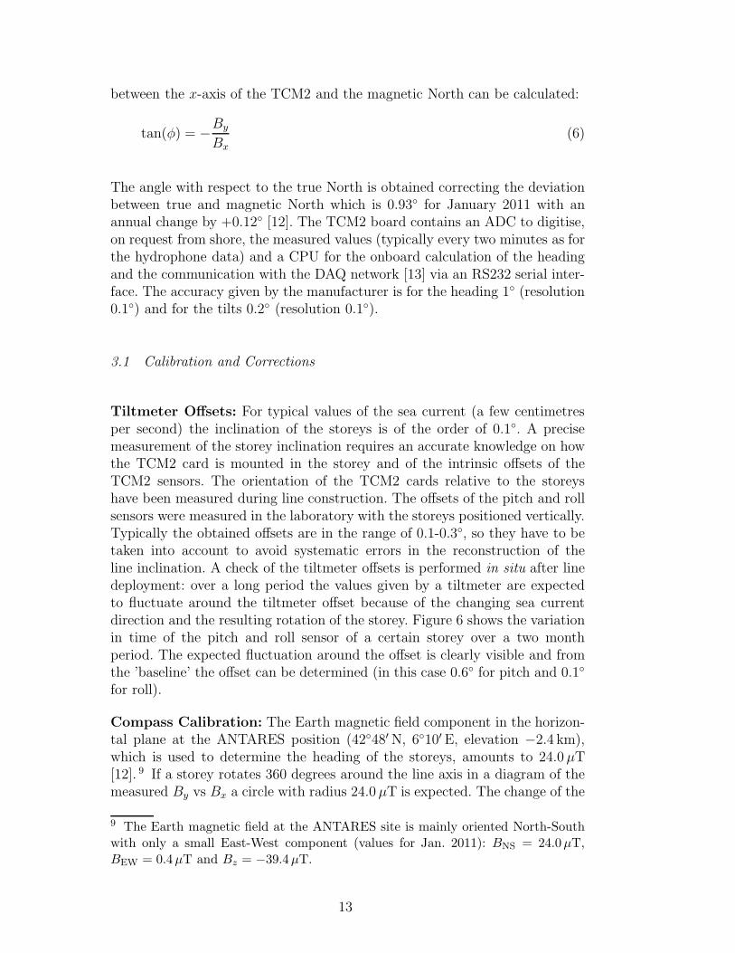
Tiltmeter Offsets: For typical values of the sea current (a few centimetresper second) the inclination of the storeys is of the order of 0.1◦. A precisemeasurement of the storey inclination requires an accurate knowledge on howthe TCM2 card is mounted in the storey and of the intrinsic offsets of theTCM2 sensors. The orientation of the TCM2 cards relative to the storeyshave been measured during line construction. The offsets of the pitch and rollsensors were measured in the laboratory with the storeys positioned vertically.Typically the obtained offsets are in the range of 0.1-0.3◦, so they have to betaken into account to avoid systematic errors in the reconstruction of theline inclination. A check of the tiltmeter offsets is performed in situ after linedeployment: over a long period the values given by a tiltmeter are expectedto fluctuate around the tiltmeter offset because of the changing sea currentdirection and the resulting rotation of the storey. Figure 6 shows the variationin time of the pitch and roll sensor of a certain storey over a two monthperiod. The expected fluctuation around the offset is clearly visible and fromthe ’baseline’ the offset can be determined (in this case 0.6◦ for pitch and 0.1◦
for roll).
Compass Calibration: The Earth magnetic field component in the horizon-tal plane at the ANTARES position (42◦48′ N, 6◦10′E, elevation −2.4 km),which is used to determine the heading of the storeys, amounts to 24.0µT[12]. 9 If a storey rotates 360 degrees around the line axis in a diagram of themeasured By vs Bx a circle with radius 24.0µT is expected. The change of the
9 The Earth magnetic field at the ANTARES site is mainly oriented North-Southwith only a small East-West component (values for Jan. 2011): BNS = 24.0µT,BEW = 0.4µT and Bz = −39.4µT.
13
month11 11.5 12 12.5
pitc
h [d
eg]
-2
-1
0
1
2
month11 11.5 12 12.5
roll
[deg
]
-2
-1
0
1
2
Fig. 6. Measured pitch and roll values for Line 12 storey 9 in Nov./Dec. 2010 (forexplanations see text).
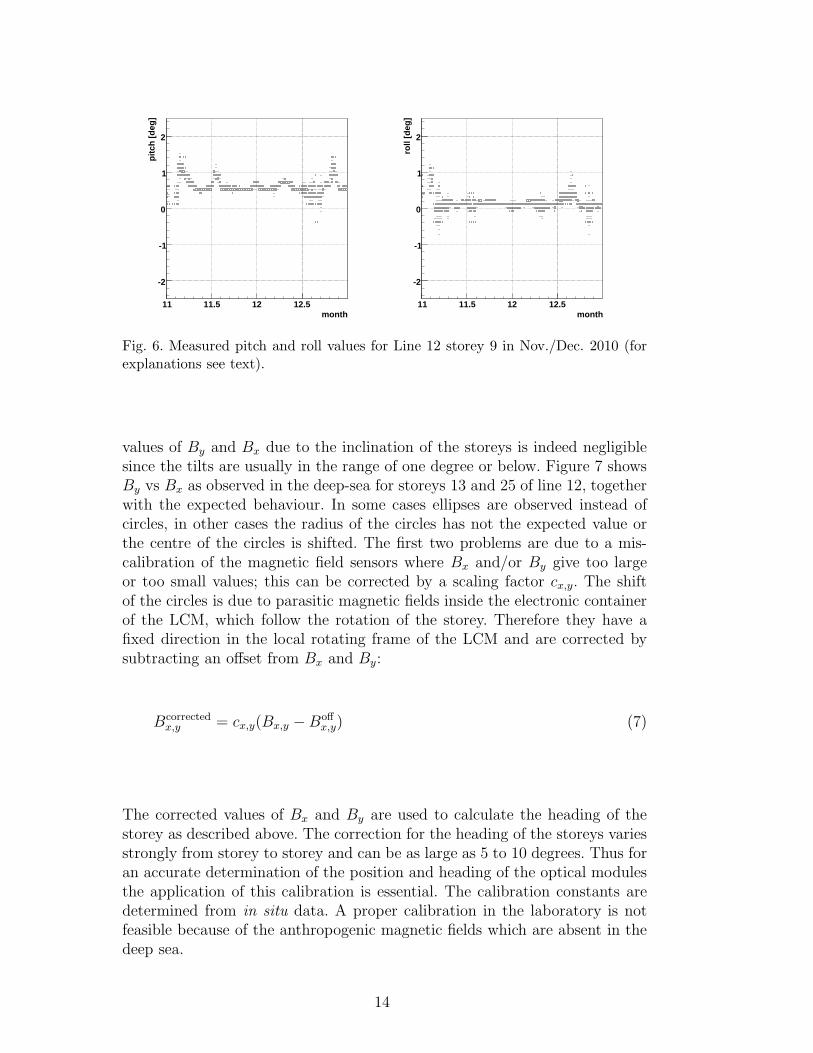
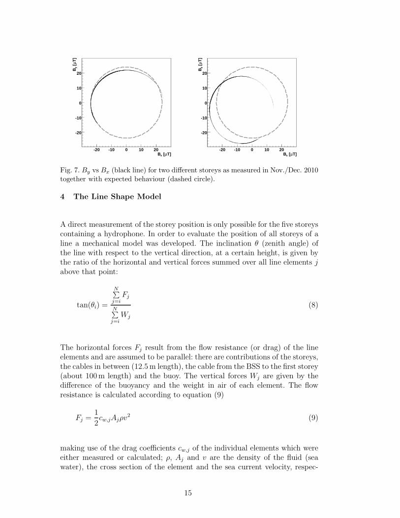
values of By and Bx due to the inclination of the storeys is indeed negligiblesince the tilts are usually in the range of one degree or below. Figure 7 showsBy vs Bx as observed in the deep-sea for storeys 13 and 25 of line 12, togetherwith the expected behaviour. In some cases ellipses are observed instead ofcircles, in other cases the radius of the circles has not the expected value orthe centre of the circles is shifted. The first two problems are due to a mis-calibration of the magnetic field sensors where Bx and/or By give too largeor too small values; this can be corrected by a scaling factor cx,y. The shiftof the circles is due to parasitic magnetic fields inside the electronic containerof the LCM, which follow the rotation of the storey. Therefore they have afixed direction in the local rotating frame of the LCM and are corrected bysubtracting an offset from Bx and By:
Bcorrectedx,y = cx,y(Bx,y −Boff
x,y) (7)
The corrected values of Bx and By are used to calculate the heading of thestorey as described above. The correction for the heading of the storeys variesstrongly from storey to storey and can be as large as 5 to 10 degrees. Thus foran accurate determination of the position and heading of the optical modulesthe application of this calibration is essential. The calibration constants aredetermined from in situ data. A proper calibration in the laboratory is notfeasible because of the anthropogenic magnetic fields which are absent in thedeep sea.
14
T]µ [xB-20 -10 0 10 20
T]
µ [ y
B
-20
-10
0
10
20
T]µ [xB-20 -10 0 10 20
T]
µ [ y
B
-20
-10
0
10
20
Fig. 7. By vs Bx (black line) for two different storeys as measured in Nov./Dec. 2010together with expected behaviour (dashed circle).
4 The Line Shape Model
A direct measurement of the storey position is only possible for the five storeyscontaining a hydrophone. In order to evaluate the position of all storeys of aline a mechanical model was developed. The inclination θ (zenith angle) ofthe line with respect to the vertical direction, at a certain height, is given bythe ratio of the horizontal and vertical forces summed over all line elements jabove that point:
tan(θi) =
N∑
j=iFj
N∑
j=iWj
(8)
The horizontal forces Fj result from the flow resistance (or drag) of the lineelements and are assumed to be parallel: there are contributions of the storeys,the cables in between (12.5m length), the cable from the BSS to the first storey(about 100m length) and the buoy. The vertical forces Wj are given by thedifference of the buoyancy and the weight in air of each element. The flowresistance is calculated according to equation (9)
Fj =1
2cw,jAjρv
2 (9)
making use of the drag coefficients cw,j of the individual elements which wereeither measured or calculated; ρ, Aj and v are the density of the fluid (seawater), the cross section of the element and the sea current velocity, respec-
15
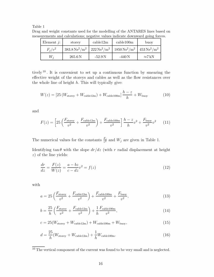
Table 1Drag and weight constants used for the modelling of the ANTARES lines based onmeasurements and calculations; negative values indicate downward going forces.
Element j: storey cable12m cable100m buoy
Fj/v2 383.8Ns2/m2 222Ns2/m2 1850Ns2/m2 453Ns2/m2
Wj 265.6N -52.9N -440N ≈7 kN
tively 10 . It is convenient to set up a continuous function by smearing theeffective weight of the storeys and cables as well as the flow resistances overthe whole line of height h. This will typically give:
W (z) = [25 (Wstorey +Wcable12m) +Wcable100m]h− z
h+Wbuoy (10)
and
F (z) =[
25(
Fstorey
v2+
Fcable12m
v2
)
+Fcable100m
v2
]
h− z
hv2 +
Fbuoy
v2v2 (11)
The numerical values for the constants Fj
v2and Wj are given in Table 1.
Identifying tan θ with the slope dr/dz (with r radial displacement at heightz) of the line yields:
dr
dz=
F (z)
W (z)=
a− bz
c− dzv2 = f(z) (12)
with
a = 25(
Fstorey
v2+
Fcable12m
v2
)
+Fcable100m
v2+
Fbuoy
v2, (13)
b =25
h
(
Fstorey
v2+
Fcable12m
v2
)
+1
h
Fcable100m
v2, (14)
c = 25(Wstorey +Wcable12m) +Wcable100m +Wbuoy, (15)
d =25
h(Wstorey +Wcable12m) +
1
hWcable100m. (16)
10 The vertical component of the current was found to be very small and is neglected.
16
By integration of equation (12) over z, for a given value of the sea current v,the radial displacement r(z) is obtained.
r(z) =
z∫
0
f(z′)dz′ =
[
b
dz −
ad− bc
d2ln
(
1−d
cz
)]
v2 (17)
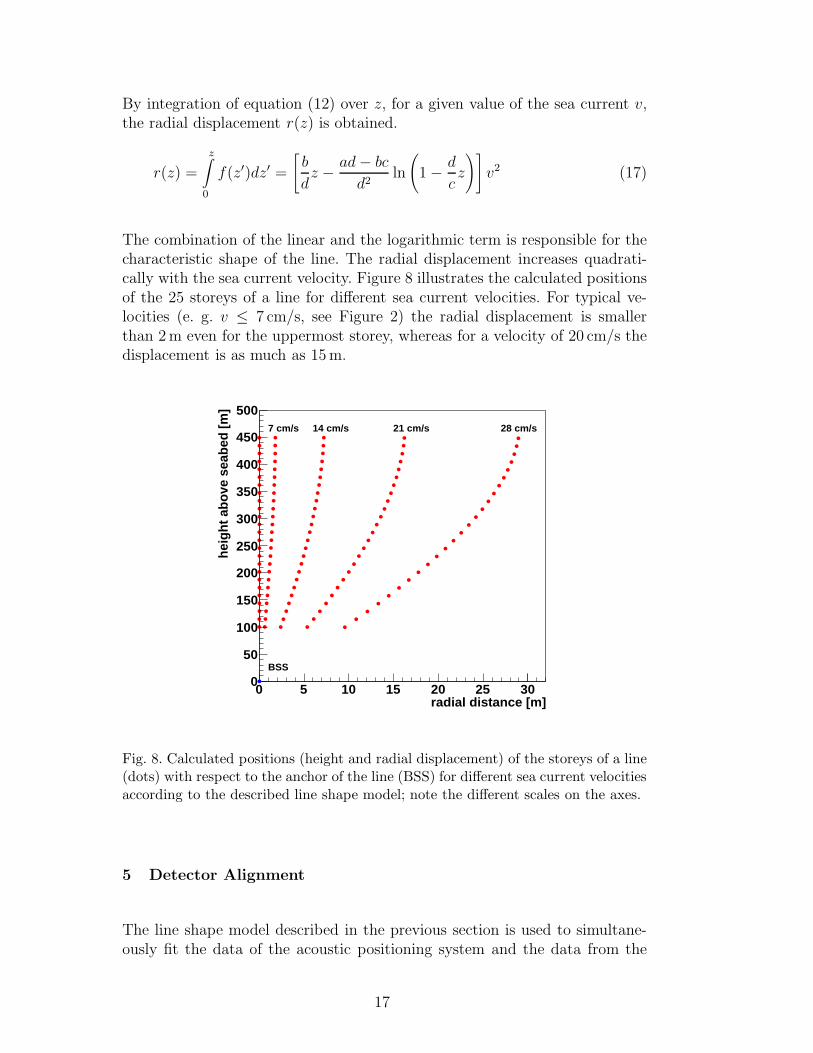
The combination of the linear and the logarithmic term is responsible for thecharacteristic shape of the line. The radial displacement increases quadrati-cally with the sea current velocity. Figure 8 illustrates the calculated positionsof the 25 storeys of a line for different sea current velocities. For typical ve-locities (e. g. v ≤ 7 cm/s, see Figure 2) the radial displacement is smallerthan 2m even for the uppermost storey, whereas for a velocity of 20 cm/s thedisplacement is as much as 15m.
radial distance [m]0 5 10 15 20 25 30
heig
ht a
bove
sea
bed
[m]
0
50
100
150
200
250
300
350
400
450
5007 cm/s 14 cm/s 21 cm/s 28 cm/s
BSS
Fig. 8. Calculated positions (height and radial displacement) of the storeys of a line(dots) with respect to the anchor of the line (BSS) for different sea current velocitiesaccording to the described line shape model; note the different scales on the axes.
5 Detector Alignment
The line shape model described in the previous section is used to simultane-ously fit the data of the acoustic positioning system and the data from the
17
compass-tiltmeter system. The only free parameter is the current velocity: theline shape equation (17) can directly be used to fit the position of the fivehydrophones from acoustic triangulation taking into account the known BSSposition (anchor point of the line). Simultaneously the inclination angles ofthe 25 storeys of a line, which correspond to dr
dz, are fit according to equation
(12). In practice, a two-dimensional χ2-fit is performed on the x and y compo-nents of equations (12) and (17) with vx and vy (components of the sea currentvelocity in the horizontal plane) as fit parameters. This yields in addition tothe radial displacement r also the direction of the line inclination Ψ:
tanΨ =vyvx
(18)
For the calculation of the χ2 the respective Gaussian errors – 5 cm for posi-tions from triangulation, 1 degree for headings and 0.2 degrees for pitch androll – are taken into account. From the radial displacement and the line in-clination the three-dimensional positions of all storeys are calculated. Everytwo minutes, updates of the positions and orientations of the optical modulesare thus available. The position of the centre of each storey and three anglesdescribing the orientation of the storey are stored in a database, together withthe errors on the respective quantities obtained from error propagation. Thisprocedure provides the complete geometry of the detector required for muontrack reconstruction.
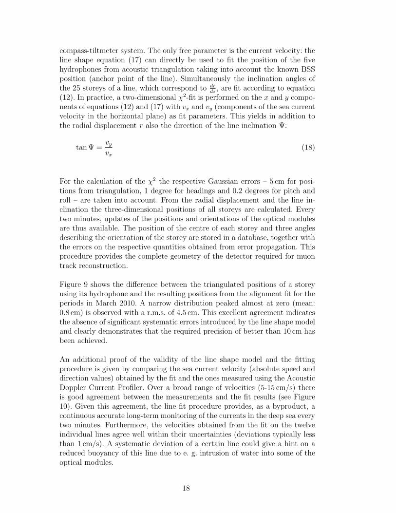
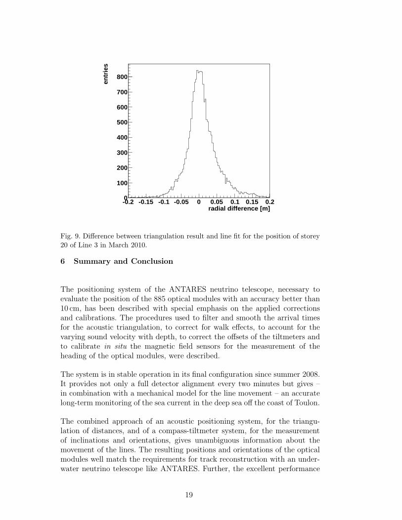
Figure 9 shows the difference between the triangulated positions of a storeyusing its hydrophone and the resulting positions from the alignment fit for theperiods in March 2010. A narrow distribution peaked almost at zero (mean:0.8 cm) is observed with a r.m.s. of 4.5 cm. This excellent agreement indicatesthe absence of significant systematic errors introduced by the line shape modeland clearly demonstrates that the required precision of better than 10 cm hasbeen achieved.
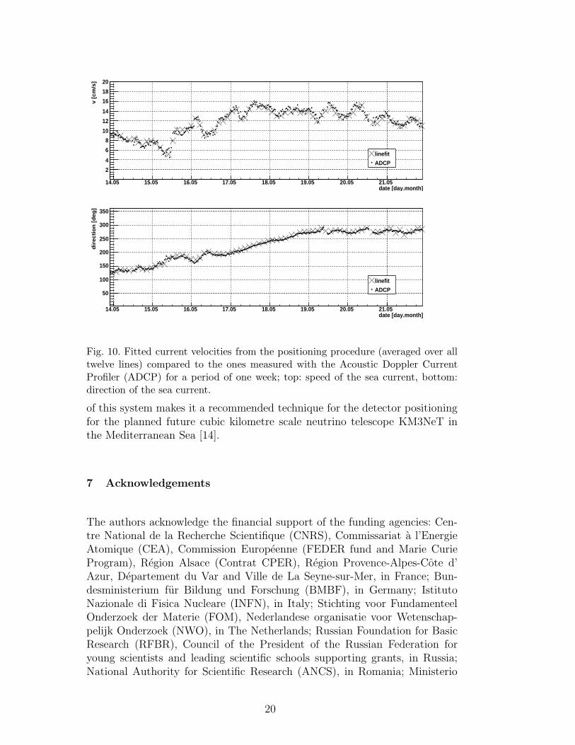
An additional proof of the validity of the line shape model and the fittingprocedure is given by comparing the sea current velocity (absolute speed anddirection values) obtained by the fit and the ones measured using the AcousticDoppler Current Profiler. Over a broad range of velocities (5-15 cm/s) thereis good agreement between the measurements and the fit results (see Figure10). Given this agreement, the line fit procedure provides, as a byproduct, acontinuous accurate long-term monitoring of the currents in the deep sea everytwo minutes. Furthermore, the velocities obtained from the fit on the twelveindividual lines agree well within their uncertainties (deviations typically lessthan 1 cm/s). A systematic deviation of a certain line could give a hint on areduced buoyancy of this line due to e. g. intrusion of water into some of theoptical modules.
18
radial difference [m]-0.2 -0.15 -0.1 -0.05 0 0.05 0.1 0.15 0.2
entr
ies
0
100
200
300
400
500
600
700
800
Fig. 9. Difference between triangulation result and line fit for the position of storey20 of Line 3 in March 2010.
6 Summary and Conclusion
The positioning system of the ANTARES neutrino telescope, necessary toevaluate the position of the 885 optical modules with an accuracy better than10 cm, has been described with special emphasis on the applied correctionsand calibrations. The procedures used to filter and smooth the arrival timesfor the acoustic triangulation, to correct for walk effects, to account for thevarying sound velocity with depth, to correct the offsets of the tiltmeters andto calibrate in situ the magnetic field sensors for the measurement of theheading of the optical modules, were described.
The system is in stable operation in its final configuration since summer 2008.It provides not only a full detector alignment every two minutes but gives –in combination with a mechanical model for the line movement – an accuratelong-term monitoring of the sea current in the deep sea off the coast of Toulon.
The combined approach of an acoustic positioning system, for the triangu-lation of distances, and of a compass-tiltmeter system, for the measurementof inclinations and orientations, gives unambiguous information about themovement of the lines. The resulting positions and orientations of the opticalmodules well match the requirements for track reconstruction with an under-water neutrino telescope like ANTARES. Further, the excellent performance
19
date [day.month]14.05 15.05 16.05 17.05 18.05 19.05 20.05 21.05
v [c
m/s
]
2
4
6
8
10
12
14
16
18
20
linefit
ADCP
date [day.month]14.05 15.05 16.05 17.05 18.05 19.05 20.05 21.05
dire
ctio
n [
de
g]
50
100
150
200
250
300
350
linefit
ADCP
Fig. 10. Fitted current velocities from the positioning procedure (averaged over alltwelve lines) compared to the ones measured with the Acoustic Doppler CurrentProfiler (ADCP) for a period of one week; top: speed of the sea current, bottom:direction of the sea current.
of this system makes it a recommended technique for the detector positioningfor the planned future cubic kilometre scale neutrino telescope KM3NeT inthe Mediterranean Sea [14].
7 Acknowledgements
The authors acknowledge the financial support of the funding agencies: Cen-tre National de la Recherche Scientifique (CNRS), Commissariat a l’EnergieAtomique (CEA), Commission Europeenne (FEDER fund and Marie CurieProgram), Region Alsace (Contrat CPER), Region Provence-Alpes-Cote d’Azur, Departement du Var and Ville de La Seyne-sur-Mer, in France; Bun-desministerium fur Bildung und Forschung (BMBF), in Germany; IstitutoNazionale di Fisica Nucleare (INFN), in Italy; Stichting voor FundamenteelOnderzoek der Materie (FOM), Nederlandese organisatie voor Wetenschap-pelijk Onderzoek (NWO), in The Netherlands; Russian Foundation for BasicResearch (RFBR), Council of the President of the Russian Federation foryoung scientists and leading scientific schools supporting grants, in Russia;National Authority for Scientific Research (ANCS), in Romania; Ministerio
20
de Ciencia e Innovacion (MICINN) and Prometeo of Generalitat Valenciana,in Spain. We further acknowledge the technical support of Ifremer, AIM andFoselev Marine for the sea operations, the CC-IN2P3 for the computing fa-cilities and the team of the former GENISEA company for their importantcontribution in the development of the acoustic positioning system.
References
[1] M. Ageron et al. (ANTARES Collaboration), Nucl. Instrum. Meth. A 656 (2011)11-38.
[2] J. A. Aguilar et al. (ANTARES Collaboration), Nucl. Instrum. Meth. A 626-627(2011) 128-143.
[3] J. A. Aguilar et al. (ANTARES Collaboration), Phys. Lett. B 696 (2011) 16-22.
[4] S. Adrian Martinez et al. (ANTARES Collaboration), Astrophys. J. Lett. 743(2011) L14-L19.
[5] P. Amram et al. (ANTARES Collaboration), Nucl. Instrum. Meth. A484 (2002)369-383.
[6] J. A. Aguilar et al. (ANTARES Collaboration), Astropart. Phys. 34 (2011) 652-662.
[7] J. A. Aguilar et al. (ANTARES Collaboration). Astropart. Phys. 34 (2011) 539-549.
[8] Chen and Millero, J. Acoust. Soc. Am., Vol. 62, No. 5, 1129-1135, Nov. 1977.
[9] G. Halladjian, Ph.D. Thesis, Universite de la Mediterranee - Aix Marseille II,France (2010), http://antares.in2p3.fr/.
[10] R. E. Francois, G. R. Garrison, J. Acoust. Soc. Am. 72(6) (1982) 1879-1890.
[11] R. J. Urick, Principles of underwater sound, Peninsula Publishing, Los Altos(1983), ISBN 0-932146-62-7.
[12] National Geophysical DATA Center: Earth magnetic field calculator,http://www.ngdc.noaa.gov/geomag/magfield.shtml.
[13] J. A. Aguilar et al. (ANTARES Collaboration), Nucl. Instrum. Meth. A 570(2007) 107-116.
[14] KM3NeT Technical Design Report (ISBN 978-90-6488-033-9), available athttp://www.km3net.org/.
21
Related Documents