English 1/2016 The People Mover System

Welcome message from author
This document is posted to help you gain knowledge. Please leave a comment to let me know what you think about it! Share it to your friends and learn new things together.
Transcript

English1/2016
The People Mover System

Application
in combination with suspension track system
in combination with skid tracks
in combination with fl oor conveyors

1
People Movers
Interchangeable platform /Stage
Project Integration Management
installation of conveyors within the platform according to requirements
replaceable with interchangeable platforms
required time for replacement: approximately 15 minutes
Application
• aluminium base frame
• min. 120 mm total height
• belt options available
• internal drive
• belt speed: 0 - 10 m/min
optional• fi re safety specifi cation: B1 compliant version
• electrostatic discharge: ESD compliant version
• power supply (electricity, light, water)
• lights
• oil drip trays
• servicing and access points
• variable working heights
optional• fi re safety specifi cation: B1 compliant version
• electrostatic discharge: ESD compliant version
• project implementation
• delivery
• assembly and installation management
Continuous operation
Tandem drive
Symbols

2
600 mm
450 mm400 mm
150 mm
600 mm
450 mm400 mm
150 mm
Variable conveyor setup
Variable working height
conveyor setup with platform
typical skid conveyor confi guration
height adjustment for conveyor and platform incline and decline (up to 7°) per platform
conveyor setup with height adjustable platform
The People Mover System
top edge of skid conveyortop edge of
people mover
fl oor level
min.
120 mm
50 mm inclining conveyor

3
Roller cover
Dirt collection tray
Electrical connection
Drive unit
drive unit with spring loaded PVC clearing
strips prevents collection of small parts
easy cleaning from above
connection terminal with C4A circuit breaker in each conveyor
various connections for subsequent and parallel units
speed adjustment by potentiometer external speed adjustment
maintenance free drive and idler unit, replaceable from above
The People Mover System
cable outlet
connection terminal
circuit breaker
cable inlet
Potentiometer PLC

4
Conveyor People mover ï 5-7• Type 5721
• Type 5722
• Type 5723
Belt type ï 10-23• Habasit M2420 Flat Top 1"
• Habasit M2423 Non Slip 1"
• Forbo Siegling S8-0 FLT
• Uni-chains QNB-C
• Uni-chains QNB-Rough
• System Plast 2250 FT
Interchangeable platform / ï 24-29 Stage • Interchangeable platform
• Stage
Drive ï 30• AC servo motor with servo drive 1 Type Minas A4
• Planetary gear box 2 Type PLE 80/90
Control methods ï 32-34• servo drive inside the conveyor
- speed adjustment via potentiometer
- speed adjustment according to external
index value
• servo drive with external control panel
- speed adjustment according to external
index value
Plastic link chain
Interchangeable platform / Stage
Drive
Control
The People Mover System
Layout
parallel
conveyor
conveyormaster conveyor
serial
index value0-10 V

5
People moverType 5.721height: 120 mm• motor capacity 750 Watt• internal drive• stainless steel sliding surface• 320 kg continuous load
People mover with plastic link chain
ImplementationAn integrated design (motor, control, drive shaft and bearings) housed within the conveyor frame
creates a uniform exterior surface.
High stability and drive capacity combined with low overall height and weight allow for a variety of
applications. Stainless steel surfaces cater to abrasive dust environments.
patent No. 102007017628
AA = Axle distance
BG = Total width
GB = Belt width
LE = Installation dimension
Technical data
transported weight: 320 kg continuous load (4 people)
480 kg temporary maximum load (6 people)
belt width: app. 600 - 1,540 mm ï 18-19
total width: app. 650 - 1,600 mm ï 18-19
total length: 1,500 - 10,000 mm
base frame: aluminium extrusion, unanodized
sliding surface: stainless steel sheet
belt material: as required ï 10-23
motor: AC servo motor with servo drive
nominal power: PN 750 W
torque: nominal 2.4 Nm, peak 7.1 Nm
nominal RPM: 1,100 min-1
transmission: planetary gear box PLE 80/90 ï 30
ratio: i40 / i100 ï 30
torque: 110 - 120 Nm ï 30
speed: 0 - 7 m/min (± 1.5%), accelaration time 2 - 3 sec.
drive orientation: pulling in direction of travel
control: servo drive inside the conveyor or external ï 32-34
speed adjustment via potentiometer ï 32-34
or according to external index value
LG = Total length
adjusting range 3 mm
view
BB

6
People moverType 5.722height: 120 mm• motor capacity 750 Watt• internal drive• PVC sliding surface• 600 kg continuous load
People mover with plastic link chain
ImplementationAn integrated design (motor, control, drive shaft and bearings) housed within the conveyor frame
creates a uniform exterior surface.
High stability and drive capacity combined with low overall height and weight allow for a variety of
applications. The PVC sliding surface reduces the friction, which allows to transport high loads at a
reduced drive power.
patent No. 102007017628
AA = Axle distance
BG = Total width
GB = Belt width
LE = Installation dimension
Technical data
transported weight: 600 kg continuous load
800 kg temporary maximum load
belt width: app. 600 - 1,540 mm ï 18-19
total width: app. 650 - 1,600 mm ï 18-19
total length: 1,500 - 10,000 mm
base frame: aluminium extrusion, unanodized
sliding surface: PVC panel
belt material: as required ï 10-23
motor: AC servo motor with servo drive
nominal power: PN 750 W
torque: nominal 2.4 Nm, peak 7.1 Nm
nominal RPM: 1,100 min-1
transmission: planetary gear box PLE 80/90 ï 30
ratio: i40 / i100 ï 30
torque: 110 - 120 Nm ï 30
speed: 0 - 7 m/min (± 1.5%), accelaration time 2 - 3 sec.
drive orientation: pulling in direction of travel
control: servo drive inside the conveyor or external ï 32-34
speed adjustment via potentiometer ï 32-34
or according to external index value
LG = Total length
adjusting range 3 mm
view
BB
7
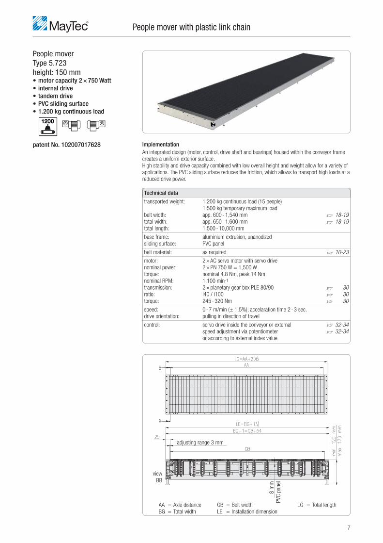
People moverType 5.723height: 150 mm• motor capacity 2 × 750 Watt• internal drive• tandem drive• PVC sliding surface• 1.200 kg continuous load
People mover with plastic link chain
ImplementationAn integrated design (motor, control, drive shaft and bearings) housed within the conveyor frame
creates a uniform exterior surface.
High stability and drive capacity combined with low overall height and weight allow for a variety of
applications. The PVC sliding surface reduces the friction, which allows to transport high loads at a
reduced drive power.
patent No. 102007017628
AA = Axle distance
BG = Total width
GB = Belt width
LE = Installation dimension
Technical data
transported weight: 1,200 kg continuous load (15 people)
1,500 kg temporary maximum load
belt width: app. 600 - 1,540 mm ï 18-19
total width: app. 650 - 1,600 mm ï 18-19
total length: 1,500 - 10,000 mm
base frame: aluminium extrusion, unanodized
sliding surface: PVC panel
belt material: as required ï 10-23
motor: 2 × AC servo motor with servo drive
nominal power: 2 × PN 750 W = 1,500 W
torque: nominal 4.8 Nm, peak 14 Nm
nominal RPM: 1,100 min-1
transmission: 2 × planetary gear box PLE 80/90 ï 30
ratio: i40 / i100 ï 30
torque: 245 - 320 Nm ï 30
speed: 0 - 7 m/min (± 1.5%), accelaration time 2 - 3 sec.
drive orientation: pulling in direction of travel
control: servo drive inside the conveyor or external ï 32-34
speed adjustment via potentiometer ï 32-34
or according to external index value
LG = Total length
adjusting range 3 mm
view
BB
8 m
m
PVC
pan
el

8
1
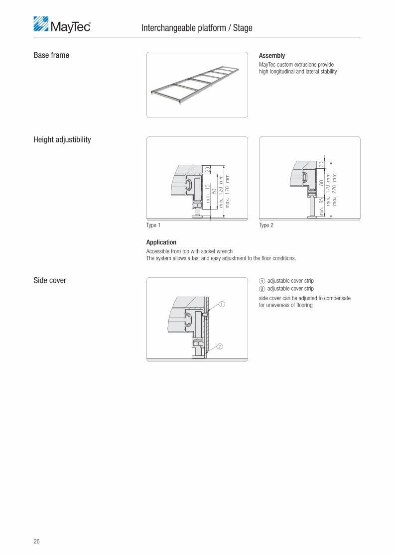
Base frame
ApplicationAccessible from top with socket wrench
The system allows a fast and easy adjustment to the fl oor conditions.
Type 1 Type 2
Height adjustibility
Side cover
Functional lengths
People mover with plastic link chain
AssemblyMayTec custom extrusions provide
high longitudinal and lateral stability
1 adjustable cover strip
side cover can be adjusted to compensate
for uneveness of fl ooring
FL = functional length
LG = total length
ÜL = transmission length
conduit conduit conduit
9
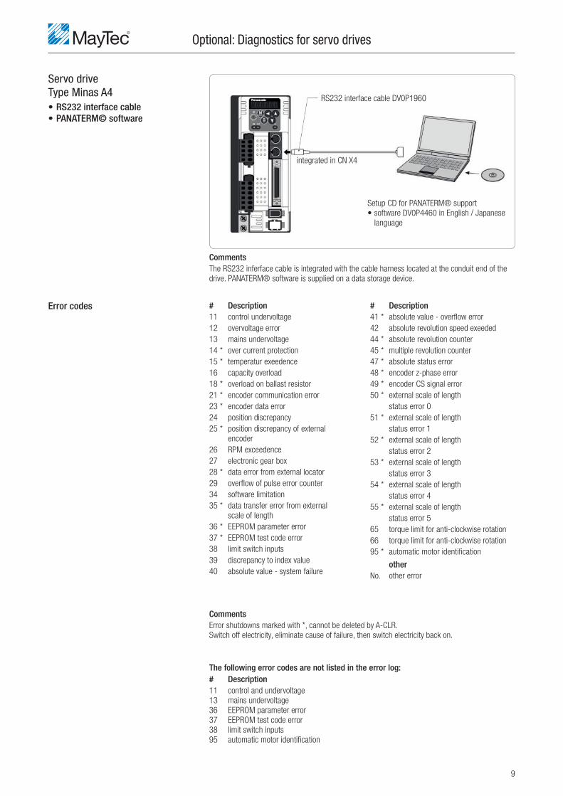
Servo driveType Minas A4• RS232 interface cable• PANATERM© software
Error codes
Optional: Diagnostics for servo drives
# Description11 control undervoltage
12 overvoltage error
13 mains undervoltage
14 * over current protection
15 * temperatur exeedence
16 capacity overload
18 * overload on ballast resistor
21 * encoder communication error
23 * encoder data error
24 position discrepancy
25 * position discrepancy of external
encoder
26 RPM exceedence
27 electronic gear box
28 * data error from external locator
29 overfl ow of pulse error counter
34 software limitation
35 * data transfer error from external
scale of length
36 * EEPROM parameter error
37 * EEPROM test code error
38 limit switch inputs
39 discrepancy to index value
40 absolute value - system failure
# Description 41 * absolute value - overfl ow error
42 absolute revolution speed exeeded
44 * absolute revolution counter
45 * multiple revolution counter
47 * absolute status error
48 * encoder z-phase error
49 * encoder CS signal error
50 * external scale of length
status error 0
51 * external scale of length
status error 1
52 * external scale of length
status error 2
53 * external scale of length
status error 3
54 * external scale of length
status error 4
55 * external scale of length
status error 5
65 torque limit for anti-clockwise rotation
66 torque limit for anti-clockwise rotation
95 * automatic motor identifi cation
otherNo. other error
CommentsThe RS232 inferface cable is integrated with the cable harness located at the conduit end of the
drive. PANATERM® software is supplied on a data storage device.
CommentsError shutdowns marked with *, cannot be deleted by A-CLR.
Switch off electricity, eliminate cause of failure, then switch electricity back on.
The following error codes are not listed in the error log:# Description11 control and undervoltage
13 mains undervoltage
36 EEPROM parameter error
37 EEPROM test code error
38 limit switch inputs
95 automatic motor identifi cation
Setup CD for PANATERM® support
• software DV0P4460 in English / Japanese
language
RS232 interface cable DV0P1960
integrated in CN X4

10
Plastic link chain
Advantages
Plastic link chain basics
1. Non-slip traction created by pinion drive
2. Chain tensioning set at minimal levels
3. Trouble free and low maintenance plastic link chain belt ensures tracking
4. Plastic chain links can be used through a wide temperature range
5. No special tools required for assembly of endless plastic chain link belts
6. Damaged plastic links are quickly and easily replaced
7. Minimal spare parts inventory. Plastic links generally replaced in short pieces
8. High lateral stability
9. Easy cleaning
10. Good sliding value with low friction
11. Scuff and scratch resistant materials
12. Fire safety specifi cation: B1 compliant version ï 20
13. ESD: Electrostatic discharge compliant version ï 22 - 23

11
Plastic link chain: Overview of producers
Producer Anti-slip specifi cation class
< R9 R9 R10
Habasit Belt surface smooth plate with lug pattern
Type M2420 Flat Top 1" ï 12 M2423 Non Slip 1" ï 13
Forbo Siegling Belt surface smooth
Type S8-0 FLT ï 14
uni-chains Belt surface smooth rough surface
Type QNB-C ï 15 QNB-Rough ï 16
Forbo Siegling Belt surface smooth
Type 2250 FT ï 17

12
HabasitType M2420 Flat Top 1"• smooth plastic link chain surface
Chain module
Sprocket
Habasit product rangeType M2420 Flat Top 1"
Plastic link chain belt
closed, smooth plastic link chain surface
Technical datachain pitch: 1" (25.4 mm)
chain thickness: 8.7 mm
plastic link chain
surface: closed, smooth
anti-slip property: R9 according DIN 51130
standard widths: ï 18 - 19
Technical datanumber of teeth: 12 Z
pitch circle Ø: 99.5 mm
hub width: 14 mm
suitable for plastic
link chain: Type M2420 Flat Top 1"
chain pitch: 1" (25.4 mm)
material: PA (Polyacetal) natural
Fire safety specifi cation Electrical Material Colour old new conductivity
B fl - s1 C fl - s1 black grey dark grey
x 0% ESD
x min. 25% ESD
x min. 33% ESD
x 100% ESD
0% ESD
min. 25% ESD
min. 33% ESD
100% ESD
B1
B2
PP x x x
POM x
PP x x x
POM x
PP x x x
POM x
PP x x x
POM x
PP x x x
POM x x x
PP x x x
POM x x x
PP x x x
POM x x x
PP x x x
POM x x x

13
HabasitType M2423 Non Slip 1"• plastic link chain surface with lug pattern
Chain module
Sprocket
Habasit product rangeType M2423 Non Slip 1"
Plastic link chain belt
plastic link chain surface closed with lug pattern
Technical datachain pitch: 1" (25.4 mm)
chain thickness: 8.7 + 1.2 mm
plastic link chain
surface: closed, with lug pattern
anti-slip property: R10 according DIN
51130
standard widths: ï 18 - 19
Technical datanumber of teeth: 12 Z
pitch circle Ø: 99.5 mm
hub width: 14 mm
suitable for plastic
link chain: Type M2423 Non Slip 1"
chain pitch: 1" (25.4 mm)
material: PA (Polyacetal) natural
Fire safety specifi cation Electrical Material Colour old new conductivity
B fl - s1 C fl - s1 black grey dark grey
x 0% ESD
x min. 25% ESD
x min. 33% ESD
x 100% ESD
0% ESD
min. 25% ESD
min. 33% ESD
100% ESD
B1
B2
PP x
POM x
PP x
POM x
PP x
POM x
PP x
POM x
PP x
POM x
PP x
POM x
PP x
POM x
PP x
POM x

14
Forbo SieglingType S8-0 FLT• smooth plastic link chain surface
Chain module
Sprocket
Forbo Siegling product rangeType S8-0 FLT
Plastic link chain belt
closed, smooth plastic link chain surface
Technical datachain pitch: 1" (25.4 mm)
chain thickness: 10.5 mm
plastic link chain
surface: closed, smooth
anti-slip property:
standard widths: ï 18 - 19
Technical datanumber of teeth: 12 Z
pitch circle Ø: 99.7 mm
hub width: 14 mm
suitable for plastic
link chain: Type S8-0 FLT
chain pitch: 1" (25.4 mm)
material: PA (Polyacetal) natural
Fire safety specifi cation Electrical Material Colour old new conductivity
B fl - s1 C fl - s1 black grey dark grey
x 0% ESD
x min. 25% ESD
x min. 33% ESD
x 100% ESD
0% ESD
min. 25% ESD
min. 33% ESD
100% ESD
B1
B2
PP x
POM
PP x
POM
PP x
POM
PP x
POM
PP x
POM
PP x
POM
PP x
POM
PP x
POM
15
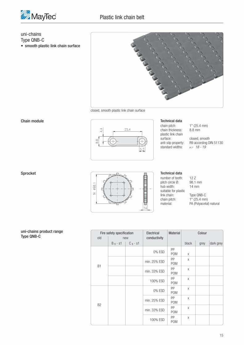
uni-chainsType QNB-C• smooth plastic link chain surface
Chain module
Sprocket
uni-chains product rangeType QNB-C
Plastic link chain belt
closed, smooth plastic link chain surface
Technical datachain pitch: 1" (25.4 mm)
chain thickness: 8.8 mm
plastic link chain
surface: closed, smooth
anti-slip property: R9 according DIN 51130
standard widths: ï 18 - 19
Technical datanumber of teeth: 12 Z
pitch circle Ø: 98.1 mm
hub width: 14 mm
suitable for plastic
link chain: Type QNB-C
chain pitch: 1" (25.4 mm)
material: PA (Polyacetal) natural
Fire safety specifi cation Electrical Material Colour old new conductivity
B fl - s1 C fl - s1 black grey dark grey
0% ESD
min. 25% ESD
min. 33% ESD
100% ESD
0% ESD
min. 25% ESD
min. 33% ESD
100% ESD
B1
B2
PP
POM x
PP x
POM
PP x
POM
PP x
POM
PP x
POM
PP x
POM
PP x
POM
PP x
POM

16
uni-chainsType QNB-Rough• plastic link chain surface with rough surface
Chain module
Sprocket
uni-chains product rangeType QNB-Rough
Plastic link chain belt
plastic link chain closed with rough surface
Technical datachain pitch: 1" (25.4 mm)
chain thickness: 9.6 mm
plastic link chain
surface: closed, with rough
surface
anti-slip property: R10 according DIN
51130
standard widths: ï 18 - 19
Technical datanumber of teeth: 12 Z
pitch circle Ø: 98.1 mm
hub width: 14 mm
suitable for plastic
link chain: Type QNB-ough
chain pitch: 1" (25.4 mm)
material: PA (Polyacetal) natural
Fire safety specifi cation Electrical Material Colour old new conductivity
B fl - s1 C fl - s1 black grey dark grey
0% ESD
min. 25% ESD
min. 33% ESD
100% ESD
0% ESD
min. 25% ESD
min. 33% ESD
100% ESD
B1
B2
PP
POM x
PP x
POM
PP x
POM
PP x
POM
PP x
POM
PP x
POM
PP x
POM
PP x
POM

17
System PlastType 2250 FT• smooth plastic link chain surface
Chain module
Sprocket
System Plast product rangeType 2250 FT
Plastic link chain belt
closed, smooth plastic link chain surface
Technical datachain pitch: 1" (25.4 mm)
chain thickness: 8.7 mm
plastic link chain
surface: closed, smooth
anti-slip property:
standard widths: ï 18 - 19
Technical datanumber of teeth: 12 Z
pitch circle Ø: 98.14 mm
hub width: 14 mm
suitable for plastic
link chain: Type 2253 FT
chain pitch: 1" (25.4 mm)
material: PA (Polyacetal) natural
Fire safety specifi cation Electrical Material Colour old new conductivity
B fl - s1 C fl - s1 black grey dark grey
x 0% ESD
x min. 25% ESD
x min. 33% ESD
x 100% ESD
0% ESD
min. 25% ESD
min. 33% ESD
100% ESD
B1
B2
PP
POM x
PP x
POM
PP x
POM
PP x
POM
PP x
POM
PP x
POM
PP x
POM
PP x
POM

18
Conveyor width forplastic link chain type
Width of chain module
short chain module
short chain module
long chain module
long chain module
cut pattern
Plastic link chain belt
595 649 610 664 607 661 595 649 10,000
680 734 686 740 683 737 680 734
765 819 762 816 759 813 765 819
850 904 838 892 835 889 850 904
935 989 914 968 911 965 935 989
1,020 1,074 991 1,045 988 1,042 1,020 1,074 6,000
1,105 1,159 1,067 1,121 1,064 1,118 1,105 1,159
1,190 1,244 1,143 1,197 1,140 1,194 1,190 1,244
1,275 1,329 1,219 1,273 1,216 1,270 1,275 1,329
1,360 1,414 1,295 1,349 1,292 1,346 1,360 1,414
1,445 1,499 1,371 1,425 1,368 1,422 1,445 1,499 5,000
1,530 1,584 1,447 1,501 1,444 1,498 1,530 1,584
85 mm 114.3 mm 76.2 mm 85 mm
170 mm 228.6 mm 152.4 mm 170 mm
17 mm 12.66 mm 12.66 mm 17 mm
Habasit Forbo Siegling uni-chains System Plast M2420 Flat Top 1" S8-0 FLT QNB-C 2250 FT
M2423 Non Slip 1" QNB-Rough
width (mm) width (mm) width (mm) width (mm) length (mm) belt conveyor 1) belt conveyor 1) belt conveyor 1) belt conveyor 1) max.
ESD
w/o with
1) conveyor width = belt width + 54 mm
cut pattern
width of chain module
cut pattern
width of chain module

19
Conveyor width forplastic link chain type
Fire safety class B1
Anti-slip specifi cation class According DIN 51130 there are fi ve different anti-slip specifi cation classes R9 to R13.
Higher classes represent higher anti-slip property.
Slip classes are specifi ed by mounting the material to the face of a ramp, oil is then poured over the surface
and a subject walks up the ramp. The incline is gradually increased until slipping occurs.
The table below determines the anti-slip class.
Plastic link chain belt
598 652 613 667 610 664 600 654 10,000
683 737 689 743 686 740 686 740
768 822 765 819 762 816 772 826
854 908 842 896 839 893 858 912
939 993 918 972 915 969 943 997
1,024 1,078 995 1,049 992 1,046 1,029 1,083 6,000
1,110 1,164 1,072 1,126 1,069 1,123 1,115 1,169
1,195 1,249 1,148 1,202 1,145 1,199 1,201 1,255
1,280 1,334 1,224 1,278 1,221 1,275 1,286 1,340
1,366 1,420 1,300 1,354 1,297 1,351 1,372 1,426
1,451 1,505 1,377 1,431 1,374 1,428 1,458 1,512 5,000
1,536 1,590 1,453 1,507 1,450 1,504 1,544 1,598
Habasit Forbo Siegling uni-chains System Plast M2420 Flat Top 1" S8-0 FLT QNB-C 2250 FT
M2423 Non Slip 1" QNB-Rough
width (mm) width (mm) width (mm) width (mm) length (mm) belt conveyor 1) belt conveyor 1) belt conveyor 1) belt conveyor 1) max.
Anti-slip Coeffi cient of friction Angle of incline Illustration specifi cation class
R9 low > 6° - 10°
coeffi cient of friction
R10 normal > 10° - 19°
coeffi cient of friction
R11 increased > 19° - 27°
coeffi cient of friction
R12 high > 27° - 35°
coeffi cient of friction
R13 very high > 35°
coeffi cient of friction
ESD
w/o with
1) conveyor width = belt width + 54 mm

20
Fire safety classesaccording DIN 4102-1
Fire safety class AMaterials of fi re safety class A must be non-combustible.
Materials like: concrete, brickwork, soil (sand, gravel, etc.) cement, mortar, stone, architectural
ceramics, glass, foam glass, cast iron, steel and aluminium belong to fi re safety class A.
Requirements for automotive applications
Fire safety class B1In order to comply with fi re safety class B1, plastic link chain modules are manufactured from
fl ame resistant materials.
The plastic link chains are assembled from injection molded modules secured by either plastic or
metal rods.
Fire safety class "new"according DIN EN 13501-1 for fl oorings
Plastic link chain
naming by Fire safety class construction "old" "new" supervision DIN 4102-1 DIN EN 13501-1
critical thermal fl ow no smoke
kW/m²
fl ame resistant B1 B fl - s1 > 8 x
fl oorings C fl - s1 4.5 to 7.9 x
normally fl ammable B2 A2 fl - s2
fl oorings B fl - s2
C fl - s2
D fl - s1 x
D fl - s2
E fl
easily fl ammable B3 F fl
fl oorings
Fire safety class BFlammable
• Fire safety class B1 Flame resistant materials belong to fi re saftey class B1.
Materials such as fl ame retardant wood and rigid foam plastic belong to this fi re safety class.
Fire must extinguish once the fi re source has been removed
• Fire safety class B2 Normally fl ammable materials belong to fi re safety class B2.
Materials like wooden parts and reconstituted timber products with a thickness > 2 mm.
• Fire safety class B3 Easily fl ammable materials belong to fi re safety class B3.
Materials like wooden parts and reconstituted timber products with a thickness < 2 mm.
Cardboard, straw or paper may not be used.

21

22
ESD version
Plastic module patterns
What is ESD?Electro Static Discharge
Transition of electrical charges between bodies with different electrostatic potentials.
Typically caused by direct contact or induced by an electrostatic fi eld.
Alternate patern with ESD modules (colour white)
Assembly in section patterns
Ratio of the ESD modules 25% to 100% depending on the assembly pattern
Example: pattern for chain width 1,020 mm
ESD ratio 25%
chain width
Plastic link chain
How is ESD created?Almost all equipment, machines and vehicles are designed using electronic components, switches
and control elements. The micro electronic components which make up these systems are
sensitive to electronic spikes and unexpected voltages.
An electrical charge is created when differing materials rub against, or come in contact with each
other. For example, if a person wearing clothing made from different types of materials walks
along an electrically isolated surface, a charge will develop on the surface of their body.
If this charged surface (the persons skin in this case) is then earthed, a discharge will occur from
the person to the earthed surface.
Electronic components can be easily damaged by such a discharge as high voltages are created.
ESD ratio 33%
chain width
ESD ratio 100%
chain width
direction of travel
standard module
ESD module

23
ESD versionMeasuring method according to: DIN EN 61340
Plastic link chain
1. Electrical grounding resistance target value: < 1 × 10 9 h
measuring method with analyser Metriso 2000 with electrode model 850
Engineering standardsDIN EN 61340-4-1
DIN EN 61340-5-1
DIN EN 61340-2-3
analyser electrode model 850
dimensions:
Ø contact rubber 63.5 mm / height 120 mm
measuring method with analyser Metriso 2000 with manual electrode model 45
Engineering standardsDIN EN 61340-4-5
DIN EN 61340-5-1
manual electrode model 45
dimensions:
Ø 25 mm / lenght 120 mm
2. Systematic resistance person - shoe - fl ooring
target value:
7,5 × 10 5 h to 3,5 × 10 7 h
3. Persons charging - walking test target value: < 100 V
electrode
model 850red black
manual
electrode
model 45
red black

24
Interchangeable platformplaceholder for people mover• 500 kg/m² maximum load
Interchangeable platform
Technical datamax. load: 500 kg/m²
height: type 1: min. 120 to max. 170 mm adjustable ï 26
type 2: min. 150 to max. 220 mm adjustable ï 26
total width (BG): 500 - 1,600 mm
total length (LG): 100 - 7,000 mm
base frame: aluminium extrusion, unanodized
BG = total width
LG = total length
view AA

25
Stage• 500 kg/m² maximum load
Stage
Technical datamax. load: 500 kg/m²
height: type 1: min. 120 to max. 170 mm adjustable ï 26
type 2: min. 150 to max. 220 mm adjustable ï 26
total width (BG): ääää
total length (LG): äääää
base frame: aluminium extrusion, unanodized
BG = total width
LG = total length
view AA
26
Base frame
ApplicationAccessible from top with socket wrench
The system allows a fast and easy adjustment to the fl oor conditions.
Type 1 Type 2
Height adjustibility
Side cover
Interchangeable platform / Stage
AssemblyMayTec custom extrusions provide
high longitudinal and lateral stability
1 adjustable cover strip
2 adjustable cover strip
side cover can be adjusted to compensate
for uneveness of fl ooring

27
Plastic sheettype RESOPAL® HPL plate
Floor plates
Technical datasheet thicknesses: 10, 12, 13, 14, 16, 18, 20, 22, 24, 25, 26 mm
sheet size: 2,180 × 915, 1,320 mm
surface: HPL (high pressure laminate) - special coating
paper with Melamin Formaldehyde resin
colour: decor at discretion
anti-slip coeffi cient: R9 according DIN 51130/BGR 181, step safety according Schuster
core material: paper with Melamin Formaldehyde resin
back side: HPL lamination (same as front side)
electrical conductivity: ESD 10 9 -10 11 hedges: 2 × 45° chamfer
silicon free: yes
layer structure
Type Fire safety Electrical Surface Abrasion class conductivity resistance
test method value
Resopal Solid F B1 0 Resopal HPL AC 5
ESD
Resopal Solid B2 0
ESD
electrical resistance DIN EN 61340-2-3 10 7 h to 10 8 h (in reference to a grounded point)
surface resistance (antistatic) DIN EN 61340-2-3 10 8 h to 10 11 h
other properties EN 438-2 refer to PDB HPL
Surface HPL coating
The chart shows typical values of electrical resistance of the conductive RESOPAL multi layer panel
The measurements are performed with a measurement voltage of 100 V and a 2.5 kg electrode
DIN EN 61340-5-1 and DIN EN 61340-4-1 Ed.2 with conductive rubber.
The electrical resistance is tested between the top surface of the material and a grounded
conductive inside layer of the HPL sheet.
The electrical resistance of the surface is tested with two 2.5 kg electrodes connected to the
panel surface.
Environmental conditions: standard climate with 18 - 25° C, relative humidity 50 - 65 %

28
Plastic sheettype DELIGNIT® industrial fl ooring
Floor plates
Technical datasheet thicknesses: 20, 25, 30, 40 mm
sheet size: 2,500 × 1,000, 1,300, 1,500 mm
core material: construction plywood according EN 636-2 as suporting construction material
for interior zones according CE 0765-CPD-0415 Blomberger Holzindustrie
B. Hausmann GmbH & Co. KG
04 EN 13986, EN 636-2 E3
wood type: beech, Brinell hardness HB = 34 N/mm²
back side: white resin coating or ESH painting
edges: 2 × 45° chamfer, transperant coating for splash guard
glueing: according EN 314-2 (class 2) adequate for most areas and protected
outside areas
silicon free: yes
Technical datasurface: painting or coating
colours: RAL 7008, 7035, 7045, 8000, transparent
anti-slip coeffi cient: R9 according DIN 51130/BGR 181 step safety according Schuster
electrical conductivity: ASF < 2.000 V electric charging
DIF 1 × 10 6 h to 1 × 10 9 h ESD 7,5 × 10 5 h to 3,5 × 10 7 h
Technical datasurface: HPL (high pressure laminate) - special coating
paper with Melamin Formaldehyd resin
colour: beech decor
anti-slip coeffi cient: R9 according DIN 51130/BGR 181 step safety according Schuster
electrical conductivity: 10 9 h to 10 11 h
layer structure
Type Fire safety Electrical Surface Abrasion class conductivity resistance
Type Fire safety Electrical Surface Abrasion class conductivity resistance
Professional L B1 ESD paint ESH-ESD 10.000 Taber
Professional B DIF lamination DIF 750 Taber
Basic L ASF paint ESH 10.000 Taber
Eco F B2 fi lm coating 750 Taber
Eco L paint
Basic HPL B1 B fl - s1 ESD Resopal HPL AC 5
Basic HPL D fl - s1
Surface painted
Surface HPL coating

29
600 mm
450 mm400 mm
150 mm
600 mm
450 mm400 mm
150 mm
Variable working height
typical skid conveyor confi guration
top edge of skid conveyortop edge of
people mover
fl oor level
Combination possibilites
Belt
Belt
Belt
Stage
Stage
Interchangeable platform
Interchangeable platform

30
AC servo motor with servo drive type Minas A4
Planetary gear boxtype PLE 80/90
Drive
Technical datamotor speed: 3.000 RPM
voltage of connection: 230 V
control voltage: 230 V
voltage deviation: +10% -15%
1 AC servo motor
2 servo drive
Technical dataoperating noise: 60 db(A)
durability: 30,000 h
protection: IP 54
Description Weight Product-No.Minas A4 400 W 1.2 kg 5MPAN.MSMD042P1C
Minas A4 750 W 2.3 kg 5MPAN.MSMD082P1C
Description Product-No.PLE 80/90 i40 5PNEU.PLE80/90-040
PLE 80/90 i100 5PNEU.PLE80/90-100
Type Torque Amperage Weight Moment of inertia rated peak 10 -4 kg N m²
Ratio Reduction stages Effi ciency Maximum torque Nm
Minas A4 400 W 1.3 Nm 3.8 Nm 4 A 1.2 kg 0.26
Minas A4 750 W 2.4 Nm 7.1 Nm 17 A 2.3 kg 0.87
1:40 2 94 % 110
1:100 3 90 % 120

31
Conveyor layout
Cable input
Cable output
E-plug connections
right
right
parallel
von links
left
front
rear
direction of travel
direction of travel
serial
direction of travel
cable input
direction of travel
direction of travel
direction of travel parallel
parallel
serial
cable output

32
Servo drive inside the conveyorspeed adjustment with potentiometer
optional Analysis output for servo drive integrated in conduit of each conveyor
Sensor cable for monitoring of motor speed at drive shaft integrated in conduit of each conveyor
Control
Electrical connection• each conveyor can be specifi ed as master or slave and can be installed in a parallel or
serial layout (up to 10 conveyors)
• mains supply 16 A with circuit breaker type C (1NPE 230 V / 50 Hz / 16 A)
• input wire 230 V (plug with connector housing Harting HAN-3A-M, 4-pin)
• input wire motor speed pre-selection plug M12, 4-pin
• 1 × output wire 230 V for parallel layout (socket Harting HAN-3A-M, 4-pin integrated in
base frame)
• 1 × output wire 230 V for serial layout (socket Harting HAN-3A-M, 4-pin integrated in
base frame)
• output wire motor speed pre-selection with status for servo drive plug M12, 4-pin
• each conveyor is protected with C4A circuit breaker
• protection IP 40
• potentiometer with socket M12, 4-pin (not included in scope of delivery)
• power supply to conveyor 1 (master) with Harting HAN-3A-M, 4-pin
conveyor
master conveyor conveyor
analysis output
sensor cable
mains
potentiometer
parallel serial
Layout
conveyor
conveyor
conduit
conduit

33
Servo drive inside the conveyorspeed adjustment according external index value
optional Analysis output for servo drive integrated in conduit of each conveyor
Sensor cable for monitoring of motor speed at drive shaft integrated in conduit of each conveyor
Control
Electrical connection• each conveyor can be specifi ed as master or slave and can be installed in a parallel or
serial layout (up to 10 conveyors)
• mains supply 16 A with circuit breaker type C (1NPE 230 V / 50 Hz / 16 A)
• input wire 230 V (plug with connector housing Harting HAN-3A-M, 4-pin)
• input wire motor speed pre-selection plug M12, 4-pin
• 1 × output wire 230 V for parallel layout (socket Harting HAN-3A-M, 4-pin integrated in
base frame)
• 1 × output wire 230 V for serial layout (socket Harting HAN-3A-M, 4-pin integrated in
base frame)
• output wire motor speed pre-selection with status for servo drive plug M12, 4-pin
• each conveyor is protected with C4A circuit breaker
• protection IP 40
• input socket for external index value M12, 4-pin
• power supply to conveyor 1 (master) with Harting HAN-3A-M, 4-pin
conveyor
master conveyor conveyor
analysis output
sensor cable
mains
index value
0 - 10 V
parallel serial
Layout
conveyor
conveyor
conduit
conduit

34
Servo drive with external control cabinetspeed adjustment according external index value
optional Analysis output for servo motor optional integrated in external control cabinet at the servo drive
Sensor cable for monitoring of motor speed at drive shaft
Control
Electrical connection• mains supply 16 A with circuit breaker type C (1NPE 230 V / 50 Hz / 16 A)
• motor speed parameter: analog index value
• inverter enabling: activation 24 V DC
• error reset: activation 24 V DC
• motor cord: type MFMCA äääää EED-S
• resolver cord: type MFECA äääää EAM-S (ä in m)
• external motor speed analysis
• counter singal 24VCD PNP switching (min. 5 Hz) with plug M12×1
• protection IP 40
• motor cord
• external control cabinet
conveyor
conveyor conveyor
analysis output
sensor cable
PLC
servo drive
external control cabinet
parallel serial
Layout
PLC
conveyor
maximum wire length 20 m (special lengths on request)
motor cord
resolver cord
servo drive
external control cabinet
PLC

35
Peop
le M
over
Sys
tem
Peo
pe
mov
ers
with
Kan
ban
tro
lleys

36
48000
24000
36000
204000
66000
60004700
48000
4700 6000
66000
204000
36000
24000
Peop
le M
over
Sys
tem
Conc
ept l
ayou
t "M
ayTe
c Pe
ople
Mov
er"
Calc
ulat
ion:
Le
ngth
W
idth
S
urfa
ce
ar
ea
110 p
cs.
6,0
00
800
528 m
2
To
tal:
528
m2
Conc
ept l
ayou
t "La
rge
Line
'
Calc
ulat
ion:
Le
ngth
W
idth
S
urfa
ce
ar
ea
2 p
cs.
48,0
00
3,2
00
308 m
2
2 p
cs.
24,0
00
3,2
00
154 m
2
2 p
cs.
66,0
00
3,2
00
423 m
2
2 p
cs.
36,0
00
3,2
00
230 m
2
To
tal:
1,11
5 m
2
conve
yor
length
conve
yor
length
conve
yor
length
conve
yor
length

Peop
le M
over
Sys
tem

GermaniaMayTec AluminiumSystemtechnik GmbHKopernikusstraße 20D - 85221 Dachau
Prefisso internazionale: +49Telefono: (0) 8131 / 33 36 - 0Telefax: (0) 8131 / 33 36 - 119e-mail: [email protected]://www.maytec.de
USAMayTec Inc.901 Wesemann DriveWest Dundee, IL 60118
Prefisso internazionale: +1Telefono: 847 - 429 - 0321Telefax: 847 - 429 - 0460e-mail: [email protected]://www.maytecinc.com
May TecDistributore ItaliaBonechi s.r.l.via A. Righi 4852100 Arezzo
Prefisso internazionale: +39Telefono: 0575 984848Telefax: 0575 980874e-mail: [email protected]://www.maytec.it
AustraliaMayTec Australia P/LUnit 8, 175 James Ruse DriveRosehill, NSW 2142
Prefisso internazionale: +61Telefono: (0) 2 / 9898 9929Telefax: (0) 2 / 9638 4086e-mail: [email protected]://www.maytec.com.au
Related Documents


