The Pennsylvania State University The Graduate School College of Engineering FLUIDIC FLEXIBLE MATRIX COMPOSITE VIBRATION TREATMENTS FOR HELICOPTER AIRFRAMES AND ROTOR BLADES A Dissertation in Mechanical Engineering by Matthew J. Krott © 2018 Matthew J. Krott Submitted in Partial Fulfillment of the Requirements for the Degree of Doctor of Philosophy December 2018

Welcome message from author
This document is posted to help you gain knowledge. Please leave a comment to let me know what you think about it! Share it to your friends and learn new things together.
Transcript
The Pennsylvania State UniversityThe Graduate SchoolCollege of Engineering
FLUIDIC FLEXIBLE MATRIX COMPOSITE
VIBRATION TREATMENTS FOR HELICOPTER AIRFRAMES
AND ROTOR BLADES
A Dissertation inMechanical Engineering
byMatthew J. Krott
© 2018 Matthew J. Krott
Submitted in Partial Fulfillmentof the Requirementsfor the Degree of
Doctor of Philosophy
December 2018
The dissertation of Matthew J. Krott was reviewed and approved∗ by the following:
Christopher D. RahnProfessor of Mechanical EngineeringDissertation Co-Advisor, Co-Chair of Committee
Edward C. SmithProfessor of Aerospace EngineeringDissertation Co-Advisor, Co-Chair of Committee
Charles E. BakisDistinguished Professor of Engineering Science and Mechanics
Bo ChengAssistant Professor of Mechanical Engineering
Jose PalaciosAssistant Professor of Aerospace Engineering
Karen A. TholeProfessor of Mechanical EngineeringDepartment Head of Mechanical & Nuclear Engineering
∗Signatures are on file in the Graduate School.
ii
Abstract
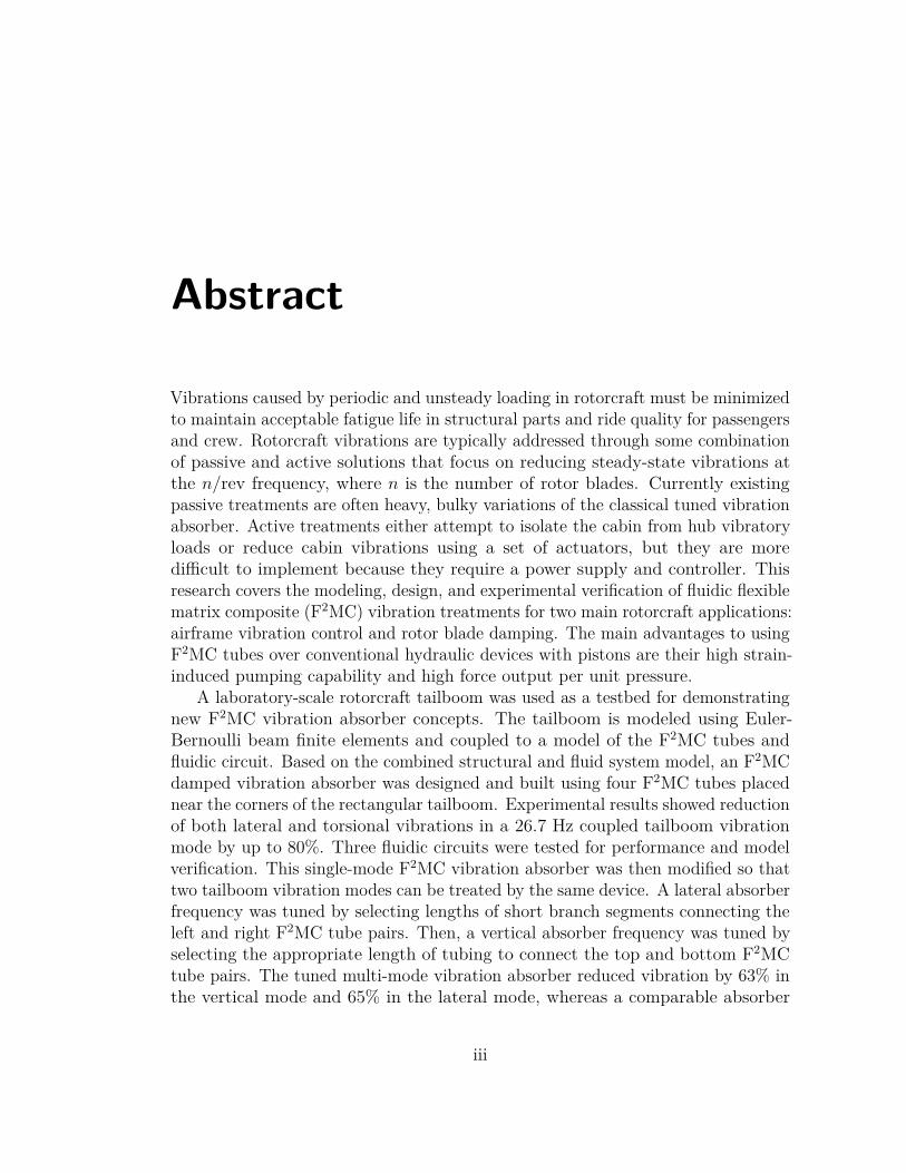
Vibrations caused by periodic and unsteady loading in rotorcraft must be minimizedto maintain acceptable fatigue life in structural parts and ride quality for passengersand crew. Rotorcraft vibrations are typically addressed through some combinationof passive and active solutions that focus on reducing steady-state vibrations atthe n/rev frequency, where n is the number of rotor blades. Currently existingpassive treatments are often heavy, bulky variations of the classical tuned vibrationabsorber. Active treatments either attempt to isolate the cabin from hub vibratoryloads or reduce cabin vibrations using a set of actuators, but they are moredifficult to implement because they require a power supply and controller. Thisresearch covers the modeling, design, and experimental verification of fluidic flexiblematrix composite (F2MC) vibration treatments for two main rotorcraft applications:airframe vibration control and rotor blade damping. The main advantages to usingF2MC tubes over conventional hydraulic devices with pistons are their high strain-induced pumping capability and high force output per unit pressure.
A laboratory-scale rotorcraft tailboom was used as a testbed for demonstratingnew F2MC vibration absorber concepts. The tailboom is modeled using Euler-Bernoulli beam finite elements and coupled to a model of the F2MC tubes andfluidic circuit. Based on the combined structural and fluid system model, an F2MCdamped vibration absorber was designed and built using four F2MC tubes placednear the corners of the rectangular tailboom. Experimental results showed reductionof both lateral and torsional vibrations in a 26.7 Hz coupled tailboom vibrationmode by up to 80%. Three fluidic circuits were tested for performance and modelverification. This single-mode F2MC vibration absorber was then modified so thattwo tailboom vibration modes can be treated by the same device. A lateral absorberfrequency was tuned by selecting lengths of short branch segments connecting theleft and right F2MC tube pairs. Then, a vertical absorber frequency was tuned byselecting the appropriate length of tubing to connect the top and bottom F2MCtube pairs. The tuned multi-mode vibration absorber reduced vibration by 63% inthe vertical mode and 65% in the lateral mode, whereas a comparable absorber
iii
designed to only treat the vertical mode reduced vibration by 68% in the verticalmode but only 42% in the lateral mode. The weight penalty from modifying thecircuit to treat both modes was only 2% of the original absorber weight.
New F2MC devices are proposed to augment the damping of both articulatedand hingeless rotor blades. The proposed device for articulated blades dissipatesenergy by using an F2MC tube to pump fluid through an orifice. In contrast,the proposed device for hingeless blades uses an F2MC tube as part of a dampedvibration absorber with a tuned inertia track. Models are derived for both conceptsto assess the feasibility of these dampers for representative articulated, stiff-inplane,and soft-inplane rotor blades. Parametric studies are conducted to understand howfluidic circuit design variables impact damper performance. For the articulatedblade damper, increasing orifice resistance increases the damping ratio of the blade-damper system at the cost of increased F2MC tube oscillatory pressures. Increasingthe accumulator capacitance reduces the F2MC damper stiffness and also increasesthe achievable damping, although the benefits diminish as the accumulator becomeslarger. A stiff-inplane hingeless blade is modeled with beam finite elements, andF2MC damped absorbers are tuned for the first chordwise bending blade mode.Eigenvalue analysis predicts an increase in the first chordwise blade mode dampingratio from a baseline of 0.02 to a range of 0.059-0.066 with the F2MC dampedabsorber. Using a large accumulator in the absorber fluidic circuit improves theabsorber effectiveness and reduces the inertance required for tuning the fluidiccircuit to a specific frequency.
Benchtop tests were conducted on a 9.7-foot diameter rotor integrated with aprototype articulated blade F2MC damper. Springs were attached to the bladeto simulate centrifugal stiffness, and both frequency-domain and time-domaindata were collected to assess damper performance. Model predictions of bladedisplacement and F2MC tube pressure were verified by experiments. Blade dampingratios in frequency-domain benchtop tests increase from a range of 0.054-0.064 withthe orifice fully closed to a range of 0.300-0.335 with the orifice tuned to maximizedamping. In time-domain benchtop tests, measured damping ratios increase from0.062-0.090 with the orifice fully closed to a range of 0.298-0.404 with the orificetuned. The benchtop tests and model verification are a key first step in developingfunctional F2MC damper technology for rotor blade applications.
iv
Table of Contents
List of Figures viii
List of Tables xiv
List of Symbols xvi
Acknowledgments xxii
Chapter 1Introduction 11.1 Background on Helicopter Vibrations . . . . . . . . . . . . . . . . . 11.2 Helicopter Vibration Control Approaches . . . . . . . . . . . . . . . 3
1.2.1 Airframe Design & Passive Solutions . . . . . . . . . . . . . 31.2.2 Active Solutions . . . . . . . . . . . . . . . . . . . . . . . . . 91.2.3 Semi-Active Solutions . . . . . . . . . . . . . . . . . . . . . 11
1.3 Rotor Blade Dampers . . . . . . . . . . . . . . . . . . . . . . . . . . 121.4 Fluidic Flexible Matrix Composite Tubes . . . . . . . . . . . . . . . 161.5 Research Objectives . . . . . . . . . . . . . . . . . . . . . . . . . . . 18
1.5.1 Airframe Application . . . . . . . . . . . . . . . . . . . . . . 191.5.2 Rotor Blade Application . . . . . . . . . . . . . . . . . . . . 20
Chapter 2Finite Element Modeling of a Tailboom with F2MC Tubes 212.1 Finite Element Modeling of Laboratory-Scale Tailboom . . . . . . . 21
2.1.1 Verification of Laboratory-Scale Tailboom Model . . . . . . 282.2 Integration of F2MC Tubes . . . . . . . . . . . . . . . . . . . . . . . 32
2.2.1 F2MC Tube & Fluidic Circuit Modeling . . . . . . . . . . . 322.2.1.1 Torsional Absorber Concept, Uncoupled Tubes . . 332.2.1.2 Bending Absorber Concept . . . . . . . . . . . . . 36
2.2.2 Combined Structural & Fluidic Circuit Model . . . . . . . . 39
v
2.3 Simulation Results & Parametric Studies . . . . . . . . . . . . . . . 432.3.1 Torsional Absorber Versus Bending Absorber Comparison . 432.3.2 Effect of Changing Inertia Track Radius . . . . . . . . . . . 492.3.3 Effect of Changing F2MC Tube Length . . . . . . . . . . . . 502.3.4 Summary of Design Study Results . . . . . . . . . . . . . . . 54
Chapter 3Experimental Demonstration of Tailboom Lateral Bending/
Torsion Mode Control 553.1 Fabrication of F2MC Tubes . . . . . . . . . . . . . . . . . . . . . . 553.2 Tailboom Experiments with F2MC Tubes . . . . . . . . . . . . . . . 59
3.2.1 Model Verification: Copper/Water Circuit . . . . . . . . . . 593.2.2 Predicted Tailboom Dynamic Load Reductions . . . . . . . . 613.2.3 Model Verification: Copper/Dense Fluid Circuit . . . . . . . 643.2.4 Model Verification: Plastic/Water Circuit . . . . . . . . . . 70
3.3 Comparisons & Summary of Results . . . . . . . . . . . . . . . . . 72
Chapter 4Multi-Mode Vibration Control Using F2MC Tubes 774.1 Experimental Demonstration of Concept . . . . . . . . . . . . . . . 78
4.1.1 Single-Mode Vertical F2MC Absorber . . . . . . . . . . . . . 804.1.2 Multi-Mode F2MC Absorber . . . . . . . . . . . . . . . . . . 834.1.3 Weight Analysis of Single-Mode & Multi-Mode Absorbers . 89
Chapter 5F2MC Rotor Blade Damper Modeling 945.1 Articulated Blade F2MC Damper . . . . . . . . . . . . . . . . . . . 94
5.1.1 Articulated Blade & Circuit Modeling . . . . . . . . . . . . 955.1.2 Case Study: Representative Articulated Blade . . . . . . . . 100
5.1.2.1 Effects of Varying Lag Angle & Orifice Resistance . 1025.1.2.2 Effect of Varying Accumulator Capacitance . . . . 1095.1.2.3 1/rev Steady State Damper Behavior . . . . . . . . 112
5.2 Hingeless Blade F2MC Damper . . . . . . . . . . . . . . . . . . . . 1135.2.1 Hingeless Blade & Circuit Modeling . . . . . . . . . . . . . . 1155.2.2 Case Study: Representative Stiff-Inplane Hingeless Blade . . 1205.2.3 Soft-Inplane Hingeless Blade F2MC Damper Options . . . . 127
Chapter 6Small-Scale Articulated Blade Damper Prototyping 1346.1 Articulated Rotor Hub Design . . . . . . . . . . . . . . . . . . . . . 134
vi
6.2 Benchtop Experiment Design & Modeling . . . . . . . . . . . . . . 1386.3 Damper Experimental Results . . . . . . . . . . . . . . . . . . . . . 144
6.3.1 Model Verification . . . . . . . . . . . . . . . . . . . . . . . 1466.3.1.1 Alternate Model Tuning Approach . . . . . . . . . 155
6.3.2 Sensitivity of Results to Operating Pressure . . . . . . . . . 1636.3.3 Sensitivity of Results to Forcing Amplitude . . . . . . . . . . 1656.3.4 Effect of Accumulator Compliance . . . . . . . . . . . . . . . 165
6.4 Experimental Results with Stainless Steel Mesh Tube . . . . . . . . 174
Chapter 7Conclusions and Future Work 1787.1 Single-Mode & Multi-Mode Tailboom Vibration Absorber . . . . . . 1797.2 Rotor Blade Dampers . . . . . . . . . . . . . . . . . . . . . . . . . . 1817.3 Recommendations for Future Work . . . . . . . . . . . . . . . . . . 183
7.3.1 General F2MC Tube Research . . . . . . . . . . . . . . . . . 1837.3.2 Blade Damper Research . . . . . . . . . . . . . . . . . . . . 185
7.3.2.1 Articulated Blade and Damper Modeling . . . . . . 1857.3.2.2 Articulated Blade Damper Hardware & Circuit . . 1877.3.2.3 Hingeless Blade Damper Modeling . . . . . . . . . 1887.3.2.4 Testing of Articulated & Hingeless Blade Dampers
in Rotating Environment . . . . . . . . . . . . . . 189
Appendix AElement Properties in Laboratory-Scale Tailboom Model 191
Appendix BTransfer Functions for F2MC Tubes & Fluidic Circuit Model 193
Appendix CRelevance of Inertia Track Symmetry 197
Appendix DMechanical Analogy for Rotor Blade with F2MC Damper 200
Appendix ESpecifications for Articulated Rotor Hub 206
Appendix FAdditional Benchtop Damper Test Results 209
Bibliography 221
vii
List of Figures
1.1 Interaction between wake vortices and horizontal tail in forward flight. 31.2 First lateral bending mode excited by turbulent flow after
separation at the rotor hub. . . . . . . . . . . . . . . . . . . . . . . 41.3 Schematic of the dynamic antiresonant vibration isolator (DAVI). . 51.4 Liquid Inertia Vibration Eliminator (LIVE) diagram and working
principle. . . . . . . . . . . . . . . . . . . . . . . . . . . . . . . . . . 61.5 Representative frequency response for a system with a tuned
vibration absorber. . . . . . . . . . . . . . . . . . . . . . . . . . . . 71.6 Diagram of pendulum absorber on a rotor blade. . . . . . . . . . . . 91.7 Photographs of elastomeric damper on the AH-64 Apache and
hydraulic damper on the CH-47 Chinook. . . . . . . . . . . . . . . . 131.8 Lift and moment distribution for an advancing blade concept
rotorcraft. . . . . . . . . . . . . . . . . . . . . . . . . . . . . . . . . 141.9 Chordwise damping of XH-59A blade versus rate of descent. . . . . 151.10 Fabrication methods for F2MC tubes. . . . . . . . . . . . . . . . . . 171.11 Volume change behavior of an F2MC tube with wind angle less
than 54.7°. . . . . . . . . . . . . . . . . . . . . . . . . . . . . . . . . 171.12 Concept for F2MC vibration absorber for transverse vibrations, as
demonstrated on laboratory-scale helicopter tailboom. . . . . . . . . 18
2.1 Semi-monocoque construction of the PSU tailboom testbed. . . . . 222.2 Laboratory-scale tailboom vibration test stand. . . . . . . . . . . . 222.3 Coordinate system and geometry of the tailboom finite element
model, with point mass locations highlighted. . . . . . . . . . . . . 242.4 Setup for measuring the tailboom baseline frequency response. . . . 292.5 Tailboom frequency response, model prediction versus experiment. . 302.6 Points along tailboom length where mode shape measurements
were taken with laser vibrometer. . . . . . . . . . . . . . . . . . . . 312.7 Normalized first lateral mode shape for the tailboom. . . . . . . . . 312.8 Normalized second lateral mode shape for the tailboom. . . . . . . . 31
viii
2.9 Apparatus for characterizing capacitance of an individual F2MC tube. 342.10 Concept using F2MC tubes to control tailboom torsional vibration. 352.11 Schematic of fluidic circuit for torsional absorber using two
uncoupled pairs of F2MC tubes. . . . . . . . . . . . . . . . . . . . . 352.12 Concept using F2MC tubes to control tailboom lateral bending
vibration. . . . . . . . . . . . . . . . . . . . . . . . . . . . . . . . . 372.13 Schematic of fluidic circuit for bending absorber using a coupled
pair of F2MC tubes. . . . . . . . . . . . . . . . . . . . . . . . . . . 382.14 Beam finite element coordinate system and F2MC tube attachment
points defined based on these coordinates. . . . . . . . . . . . . . . 422.15 Visualization of first and second lateral bending/torsion modes for
laboratory-scale tailboom. . . . . . . . . . . . . . . . . . . . . . . . 442.16 1/rev and n/rev frequencies of existing helicopters. . . . . . . . . . 452.17 Tailboom tip lateral displacement and tip twist frequency responses
with different F2MC absorber configurations. . . . . . . . . . . . . . 472.18 Tailboom frequency responses with different F2MC bending
absorbers designed using different inertia track radii. . . . . . . . . 512.19 Tailboom frequency responses with different F2MC bending
absorbers designed using different F2MC tube lengths. . . . . . . . 53
3.1 Diagram of the braided-sheath F2MC tube and end fitting design. . 563.2 Two hex nuts used to tension the F2MC tube and secure the end
fitting to the L-bracket. . . . . . . . . . . . . . . . . . . . . . . . . . 573.3 Full setup for tailboom vibration experiment with F2MC tubes,
fluidic circuit, and fill/bleed circuits. . . . . . . . . . . . . . . . . . 583.4 Side view of tailboom vibration experiment with F2MC tubes and
tuned fluidic circuit. . . . . . . . . . . . . . . . . . . . . . . . . . . 593.5 Tailboom frequency response with and without F2MC absorber
(copper/water circuit). . . . . . . . . . . . . . . . . . . . . . . . . . 623.6 Variation in tailboom tip and horizontal tail tip frequency response
with preset operating pressure of F2MC absorber. . . . . . . . . . . 633.7 Frequency response magnitude of internal moment and shear force
at 2nd tailboom node. . . . . . . . . . . . . . . . . . . . . . . . . . . 653.8 Frequency response magnitude of internal moment and shear force
at 4th tailboom node. . . . . . . . . . . . . . . . . . . . . . . . . . . 663.9 Frequency response magnitude of internal moment and shear force
at 7th tailboom node. . . . . . . . . . . . . . . . . . . . . . . . . . . 673.10 Photograph of copper fluidic circuit using water as working fluid. . 683.11 Photograph of copper fluidic circuit using dense, low-viscosity
working fluid. . . . . . . . . . . . . . . . . . . . . . . . . . . . . . . 68
ix
3.12 Tailboom frequency response with and without F2MC absorber(copper/dense fluid circuit). . . . . . . . . . . . . . . . . . . . . . . 69
3.13 Photograph of plastic fluidic circuit using water as working fluid. . . 703.14 Tailboom frequency response with and without F2MC absorber
(plastic/water circuit). . . . . . . . . . . . . . . . . . . . . . . . . . 713.15 Comparison of tailboom tip and horizontal tail tip frequency
responses for the three F2MC absorbers tested. . . . . . . . . . . . 74
4.1 Schematic of Miura’s single-mode vertical vibration absorber. . . . . 794.2 Schematic of new multi-mode, vertical and lateral vibration absorber. 794.3 Positioning of F2MC tubes for single-mode and multi-mode
vibration absorbers. . . . . . . . . . . . . . . . . . . . . . . . . . . . 804.4 Shaker setup for tailboom tip vertical forcing. . . . . . . . . . . . . 824.5 Vertical tailboom tip displacement frequency response for tailboom
tip forcing, single-mode vertical absorber. . . . . . . . . . . . . . . . 844.6 Lateral tailboom tip displacement frequency response for tailboom
tip forcing, single-mode vertical absorber. . . . . . . . . . . . . . . . 844.7 Side views of single-mode vertical and multi-mode inertia tracks
from the two F2MC absorbers. . . . . . . . . . . . . . . . . . . . . . 864.8 Vertical tailboom tip displacement frequency response, multi-mode
absorber versus single-mode vertical absorber (experiment). . . . . . 874.9 Lateral tailboom tip displacement frequency response, multi-mode
absorber versus single-mode vertical absorber (experiment). . . . . . 874.10 Horizontal tail vertical tip displacement frequency response,
multi-mode absorber versus single-mode vertical absorber(experiment). . . . . . . . . . . . . . . . . . . . . . . . . . . . . . . 88
4.11 Lateral tailboom tip displacement frequency response, with valve incircuit vertical segment open and closed. . . . . . . . . . . . . . . . 90
4.12 Weight breakdown for single-mode vertical F2MC vibration absorber. 924.13 Weight breakdown for multi-mode vertical and lateral F2MC
vibration absorber. . . . . . . . . . . . . . . . . . . . . . . . . . . . 924.14 Examples of F2MC tube attachment schemes. . . . . . . . . . . . . 93
5.1 Top view of F2MC lead-lag damper for an articulated rotor blade. . 955.2 F2MC tube and fluidic circuit model for articulated and hingeless
blade damper circuits. . . . . . . . . . . . . . . . . . . . . . . . . . 975.3 Perspective and top views of coordinate system for calculating
F2MC tube length change. . . . . . . . . . . . . . . . . . . . . . . . 99
x
5.4 Change in F2MC tube length and fiber angle α as tube shortens toits free strain active length Lfs,a with fiber angle αfs when initiallypressurized, then extends back to final active length Lt,a with fiberangle αf under centrifugal tensioning. . . . . . . . . . . . . . . . . . 102
5.5 Variation of blade damping at operating lag angles of ζo=0°, 3°,and 6°. . . . . . . . . . . . . . . . . . . . . . . . . . . . . . . . . . . 105
5.6 Blade frequency response with 1 in. diameter F2MC tube damperat different operating lag angles. . . . . . . . . . . . . . . . . . . . . 107
5.7 Variation of F2MC tube fiber angle and blade damping ratio withoperating lag angle. . . . . . . . . . . . . . . . . . . . . . . . . . . . 108
5.8 Variation of blade damping ratio with acccumulator capacitance fordifferent levels of orifice resistance. . . . . . . . . . . . . . . . . . . 110
5.9 Blade frequency response for varying accumulator capacitance. . . . 1115.10 Variation in 1/rev F2MC tube pressure amplitude with operating
lag angle for different orifice resistances. . . . . . . . . . . . . . . . 1145.11 Variation in 1/rev F2MC tube pressure amplitude with operating
lag angle for different accumulator capacitances. . . . . . . . . . . . 1145.12 Large stroke for damper on articulated blade versus smaller stroke
on hingeless blade. . . . . . . . . . . . . . . . . . . . . . . . . . . . 1155.13 Schematic of F2MC damped vibration absorber for hingeless rotor
blade. . . . . . . . . . . . . . . . . . . . . . . . . . . . . . . . . . . 1165.14 Diagram of uniform hingeless rotor blade integrated with internal
F2MC damped absorber. . . . . . . . . . . . . . . . . . . . . . . . . 1225.15 Diagram of uniform hingeless rotor blade integrated with external
F2MC damped absorber. . . . . . . . . . . . . . . . . . . . . . . . . 1225.16 Frequency responses from blade tip chordwise force input to tip
chordwise displacement for baseline stiff-inplane hingeless rotorblade and three blade-absorber systems. . . . . . . . . . . . . . . . 125
5.17 Frequency responses from blade tip chordwise force input to tipchordwise displacement for stiff-inplane blade with tuned absorbersand different accumulator capacitances. . . . . . . . . . . . . . . . . 127
5.18 Frequency responses from blade tip chordwise force input to tipchordwise displacement for soft-inplane rotor blades with tunedF2MC absorbers. . . . . . . . . . . . . . . . . . . . . . . . . . . . . 130
5.19 Mode shapes for three soft-inplane hingeless blades. . . . . . . . . . 1315.20 Frequency responses from blade tip chordwise force input to tip
chordwise displacement for soft-inplane rotor blades with F2MCdampers. . . . . . . . . . . . . . . . . . . . . . . . . . . . . . . . . . 133
5.21 Frequency responses for the case where flexure bending stiffness is25% of blade stiffness, with three different orifice resistances. . . . . 133
xi
6.1 CAD image of hub for articulated blade experiments. . . . . . . . . 1356.2 Top view of articulated rotor hub with various attachment holes
labeled. . . . . . . . . . . . . . . . . . . . . . . . . . . . . . . . . . 1366.3 Finite element analysis result showing von Mises stress distribution
in articulated rotor hub. . . . . . . . . . . . . . . . . . . . . . . . . 1376.4 Shortened Schweizer 300 rotor blade for small-scale experiments. . . 1376.5 Locations of thrust bearings and roller bearings for articulated blade. 1386.6 Schematic of benchtop tests with springs used to simulate
centrifugal stiffness. . . . . . . . . . . . . . . . . . . . . . . . . . . . 1396.7 Coupler for attaching two springs on one side of the rotor blade. . . 1406.8 Process for determining blade radial center of gravity using scale
measurements. . . . . . . . . . . . . . . . . . . . . . . . . . . . . . . 1406.9 Baseline blade frequency response with Ns = 2 springs. . . . . . . . 1426.10 Baseline blade frequency response with Ns = 4 springs. . . . . . . . 1426.11 Top view of F2MC damper in benchtop test. . . . . . . . . . . . . . 1456.12 Side view of F2MC damper highlighting spherical bearings, linear
ball bearing, and guide rod. . . . . . . . . . . . . . . . . . . . . . . 1466.13 Instrumentation for F2MC damper benchtop testing. . . . . . . . . 1466.14 Blade frequency responses generated at 60 psi with orifice fully
open and fully closed. . . . . . . . . . . . . . . . . . . . . . . . . . . 1496.15 Variation of blade frequency response with 2 springs attached and 4
springs attached, as orifice position ranges from fully open to fullyclosed. . . . . . . . . . . . . . . . . . . . . . . . . . . . . . . . . . . 150
6.16 Model correlation for lag displacement frequency response, 2-springtest, 31.5° initial fiber angle, 40 psi and 60 psi operating pressures. . 153
6.17 Model correlation for lag displacement frequency response, 4-springtest, 31.5° initial fiber angle, 40 psi and 60 psi operating pressures. . 154
6.18 Model correlation for F2MC tube pressure frequency response,2-spring test, 31.5° initial fiber angle, 40 psi and 60 psi operatingpressures. . . . . . . . . . . . . . . . . . . . . . . . . . . . . . . . . 156
6.19 Model correlation for F2MC tube pressure frequency response,4-spring test, 31.5° initial fiber angle, 40 psi and 60 psi operatingpressures. . . . . . . . . . . . . . . . . . . . . . . . . . . . . . . . . 157
6.20 Model correlation for lag displacement frequency response, 2-springtest, 40 psi operating pressure, 34.0° initial fiber angle and 60 psioperating pressure, 32.5° initial fiber angle. . . . . . . . . . . . . . . 159
6.21 Model correlation for lag displacement frequency response, 4-springtest, 40 psi operating pressure, 32.5° initial fiber angle and 60 psioperating pressure, 31.5° initial fiber angle. . . . . . . . . . . . . . . 160
xii
6.22 Model correlation for F2MC tube pressure frequency response,2-spring test, 40 psi operating pressure, 34.0° initial fiber angle and60 psi operating pressure, 32.5° initial fiber angle. . . . . . . . . . . 161
6.23 Model correlation for F2MC tube pressure frequency response,4-spring test, 40 psi operating pressure, 32.5° initial fiber angle and60 psi operating pressure, 31.5° initial fiber angle. . . . . . . . . . . 162
6.24 Fully-open orifice frequency response results at different circuitpressures for blade with 2 springs attached and 4 springs attached. . 164
6.25 Partially-closed orifice frequency response results at different circuitpressures for blade with 2 springs attached and 4 springs attached. . 164
6.26 Fully-closed orifice frequency response results at different circuitpressures for blade with 2 springs attached and 4 springs attached. . 165
6.27 Fully-open orifice frequency response results at different forcingamplitudes for blade with 2 springs attached and 4 springs attached. 166
6.28 Partially-closed orifice frequency response results at different forcingamplitudes for blade with 2 springs attached and 4 springs attached. 167
6.29 Fully-closed orifice frequency response results at different forcingamplitudes for blade with 2 springs attached and 4 springs attached. 167
6.30 Difference between blade frequency responses with and without airin accumulator, 2 springs attached and 4 springs attached. . . . . . 169
6.31 Effect of tuning orifice with 2 springs attached to blade, with andwithout air in accumulator. . . . . . . . . . . . . . . . . . . . . . . 170
6.32 Effect of tuning orifice with 4 springs attached to blade, with andwithout air in accumulator. . . . . . . . . . . . . . . . . . . . . . . 170
6.33 Blade time responses for damper configurations with and withoutair in accumulator, 40 psi operating pressure. . . . . . . . . . . . . . 171
6.34 Blade time responses for damper configurations with and withoutair in accumulator, 60 psi operating pressure. . . . . . . . . . . . . . 172
6.35 Blade time responses for damper configurations with and withoutair in accumulator, 80 psi operating pressure. . . . . . . . . . . . . . 173
6.36 Comparison between pressurized shapes of plastic mesh andstainless steel mesh F2MC tubes. . . . . . . . . . . . . . . . . . . . 176
6.37 Blade frequency responses for different orifice positions withstainless steel mesh F2MC damper, 2 springs and 4 springsattached, 60 psi operating pressure. . . . . . . . . . . . . . . . . . . 177
7.1 CAD image of attachment hardware for eliminating F2MC tubetwist by using two guide rods. . . . . . . . . . . . . . . . . . . . . . 188
xiii
List of Tables
2.1 Properties used in finite element model of laboratory-scale tailboom. 272.2 Properties used as inputs to the F2MC tube model. . . . . . . . . . 462.3 F2MC tube and tuned fluidic circuit properties for torsional and
bending F2MC absorbers. . . . . . . . . . . . . . . . . . . . . . . . 482.4 F2MC tube and tuned fluidic circuit properties for bending
absorbers using different inertia track radii. . . . . . . . . . . . . . . 502.5 F2MC tube and tuned fluidic circuit properties for bending
absorbers using different F2MC tube lengths. . . . . . . . . . . . . . 52
3.1 Fabricated F2MC tube properties and coefficients. . . . . . . . . . . 603.2 Fluidic circuit and other properties for the three test cases. . . . . . 733.3 Weights of F2MC tube and circuit components. . . . . . . . . . . . 733.4 Performance comparison between the three F2MC absorbers. . . . . 75
4.1 Revised finite element model properties and target mode propertiesfor laboratory-scale tailboom. . . . . . . . . . . . . . . . . . . . . . 82
4.2 Comparison between single-mode vertical and multi-mode F2MCabsorbers. . . . . . . . . . . . . . . . . . . . . . . . . . . . . . . . . 89
4.3 Weights of individual components in F2MC absorbers. . . . . . . . . 90
5.1 Properties for representative articulated blade based on UH-60. . . 1015.2 Properties for different diameter F2MC tubes in articulated blade
damper. . . . . . . . . . . . . . . . . . . . . . . . . . . . . . . . . . 1045.3 Properties for F2MC dampers at each operating angle. . . . . . . . 1065.4 Representative stiff-inplane hingeless rotor blade properties. . . . . 1205.5 Properties of F2MC tubes for stiff-inplane hingeless blade damped
absorbers. . . . . . . . . . . . . . . . . . . . . . . . . . . . . . . . . 1235.6 Properties of tuned fluidic circuits for stiff-inplane hingeless blade
damped absorbers. . . . . . . . . . . . . . . . . . . . . . . . . . . . 124
xiv
5.7 Characteristics from eigenvalue analysis of baseline blade andblade-F2MC absorber systems. . . . . . . . . . . . . . . . . . . . . . 125
5.8 Properties of tuned fluidic circuits for stiff-inplane hingeless bladedamped absorbers with different accumulator capacitances. . . . . . 126
5.9 Characteristics from eigenvalue analysis of blade-absorber systemswith different accumulator capacitances. . . . . . . . . . . . . . . . 126
5.10 Representative uniform and non-uniform soft-inplane hingelessrotor blade properties. . . . . . . . . . . . . . . . . . . . . . . . . . 128
5.11 Properties of F2MC tube for all three soft-inplane hingeless bladedamped absorbers. . . . . . . . . . . . . . . . . . . . . . . . . . . . 129
5.12 Properties of tuned fluidic circuits for soft-inplane hingeless bladedamped absorbers. . . . . . . . . . . . . . . . . . . . . . . . . . . . 130
5.13 Characteristics from eigenvalue analysis of soft-inplane blades withF2MC damped absorbers. . . . . . . . . . . . . . . . . . . . . . . . 131
6.1 Model F2MC tube parameters for verification cases, 31.5° initialfiber angle. . . . . . . . . . . . . . . . . . . . . . . . . . . . . . . . . 151
6.2 Model circuit parameters for verification cases, 31.5° initial fiberangle. . . . . . . . . . . . . . . . . . . . . . . . . . . . . . . . . . . 152
6.3 Model-predicted damping ratios for open, tuned, and closed orificecases, 31.5° initial fiber angle. . . . . . . . . . . . . . . . . . . . . . 155
6.4 Re-tuned parameters and model-predicted damping ratios foralternative tuning approach. . . . . . . . . . . . . . . . . . . . . . . 163
6.5 Damping ratio as calculated by logarithmic decrement from timeresponse data in Figures 6.33 through 6.35. . . . . . . . . . . . . . . 174
A.1 Finite element properties for laboratory-scale tailboom model. . . . 192
xv
List of Symbols
˙( ) derivative with respect to time∗
( ) derivative with respect to ψ
A finite element cross-sectional area
Acol cross-sectional area of fluid column in capacitance test
Aorf orifice cross-sectional area
[Asys] combined structural/fluid system model state matrix
[At] F2MC tube/fluid state matrix
[At], Bt, CtT , Dt F2MC damper fluid system state-space matrices
Bsys combined structural/fluid system model input matrix
Bt,i part of F2MC tube/fluid input matrix multiplied by xi
c1 F2MC tube axial stiffness
c2 F2MC tube force-pressure coefficient
c3 F2MC tube volume change coefficient
c4 F2MC tube capacitance
ca accumulator capacitance
cG hingeless blade geometric damping coefficient
cζ linear viscous damping coefficient
xvi
[C] finite element global damping matrix
Cd orifice flow discharge coefficient
[C]e hingeless blade element damping matrix
[Cm] finite element modal mass matrix
Ct,iT part of F2MC tube/fluid output matrix multiplied by statesξ to produce F2MC tube force Fi
d F2MC tube constant offset distance from neutral axis
ds distance from springs to lag hinge
Dt feedforward matrix from F2MC tube displacement xi toforce Fi
e lag hinge distance from axis of rotation
E Young’s modulus
EIbl soft-inplane blade bending stiffness
EIe hingeless blade element chordwise bending stiffness
EIflex soft-inplane flexure bending stiffness
Fext scalar external force input
Fext external force vector
Fi axial force acting on F2MC tube iFi
F2MC tube i finite element model load
Fint vector of internal reaction forces and moments in element[Fq]
matrix accounting for part of F2MC finite element loadmultiplied by nodal degrees of freedom
Ft F2MC damper tube force
Fx in-plane aerodynamic force per unit span, not includingaerodynamic damping forces
xvii
[Fξ]
matrix accounting for part of F2MC finite element loadmultiplied by fluid states
g acceleration of gravity
G shear modulus
[H(s)] transfer function matrix from F2MC tube displacements toF2MC tube forces
I fluid inertance (subscripts: c=circuit, b=branch, m=main,s=segment)
Ip finite element polar moment of inertia
Iyy finite element second area moment about y-axis
Izz finite element second area moment about z-axis
Iζ blade mass moment of inertia about lag hinge
J finite element torsion constant
k linear spring constant
kshak torsional stiffness contribution from shaker in benchtop test
kspr torsional stiffness contribution from springs in benchtoptest
[K] finite element global stiffness matrix
Ka,b entry in the ath row and bth column of element stiffnessmatrix
[Kel] local element stiffness matrix
[Knr]e hingeless blade element nonrotating component of stiffnessmatrix
[Krot]e hingeless blade element rotating component of stiffnessmatrix
l inertia track length (subscripts: c=circuit, s=segment)
Le finite element length
xviii
Lo initial F2MC tube length
Lo,a initial F2MC tube active length
Lt F2MC tube length after lag displacement
Lt,a F2MC tube active length after lag displacement
mb small scale blade mass
me hingeless blade element mass per unit length
[M ] finite element global mass matrix
Ma,b entry in the ath row and bth column of element mass matrix
[M ]e hingeless blade element mass matrix
Mext external moment applied about lag hinge
[Mm] finite element modal mass matrix
Mnd external nondimensional moment about lag hinge
Mt F2MC damper tube moment
n number of rotor blades
Nel number of finite elements in hingeless blade model
Ns number of springs attached to rotor blade in benchtop test
pa accumulator gas absolute pressure
pi internal pressure of F2MC tube i
pt F2MC damper tube pressure
q finite element degrees of freedom vector
qloc vector of local degrees of freedom for an element
Qi volume flow rate out of F2MC tube i
pa accumulator pressure
r rotor blade radial coordinate
xix
r inertia track radius (subscripts: c=circuit, s=segment)
rcg radial distance from lag hinge to blade center of gravity
R rotor blade radius
R fluid resistance (subscripts: c=circuit, b=branch, m=main,s=segment)
s Laplace variable
s nondimensionalized Laplace variable
Sζ blade first mass moment of inertia about lag hinge
t time
T blade oscillation period, released from rest as pendulum
u, v, w finite element translation degrees of freedom
Va accumulator gas volume
(x1, y1, z1) location of F2MC tube attachment point closer to tailboomroot
(x2, y2, z2) location of F2MC tube attachment point closer to tailboomtip
(xb, yb, zb) F2MC damper attachment point on blade
(xh, yh, zh) F2MC damper attachment point on hub
xi axial displacement of F2MC tube i
xt F2MC damper tube axial displacement
|Y (f)| magnitude of hingeless blade chordwise tip force to tipdisplacement transfer function at frequency f
Z objective function to minimize in circuit tuning
α F2MC tube fiber wind angle
αf instantaneous F2MC tube fiber angle
αo initial, unstrained F2MC tube fiber angle
xx
βχ coefficient in ΨiT corresponding to nodal degree of free-dom χ
∆h change in height of fluid column in capacitance test
∆p pressure increment in capacitance test
∆Vout volume of fluid moved out of F2MC tube in capacitancetest
ζ damping ratio or lag angle
ζo blade operating lag angle
η accumulator gas polytropic exponent
θx, θy, θz finite element rotation degrees of freedom
κI inertance frequency dependence correction factor
κR resistance frequency dependence correction factor
µ fluid dynamic viscosity
νζ blade nondimensional lag frequency (/rev)
ξ vector of states for F2MC tube/fluid subsystem dynamics
ρ material or fluid density
σ F2MC damper tube force moment arm
σi vector converting F2MC tube scalar force into finite elementload
[φ] eigenvector matrix
ψ rotor azimuth angle
Ψ scalar conversion factor from lag angle to F2MC tube dis-placement
ΨiT row vector converting nodal displacements into F2MC tubei axial displacement
ωn natural frequency
Ω rotor speed
xxi
Acknowledgments
This material is based upon work supported by the National Science FoundationGraduate Research Fellowship Program under Grant No. DGE1255832. Anyopinions, findings, and conclusions or recommendations expressed in this materialare those of the author and do not necessarily reflect the views of the NationalScience Foundation.
This research was partially funded by the Government under Agreement No.W911W6-17-2-0003. The U.S. Government is authorized to reproduce and distributereprints for Government purposes notwithstanding any copyright notation thereon.The views and conclusions contained in this document are those of the authors andshould not be interpreted as representing the official policies, either expressed orimplied, of the Aviation Development Directorate or the U.S Government.
The path to completing my Ph.D. has been long and arduous, and I am gratefulto many individuals for their help over the course of this journey. First and foremost,I would like to thank my co-advisors, Dr. Christopher Rahn and Dr. Edward Smith,for serving as outstanding mentors. Your input on my research has always beenconstructive, insightful, and valuable. I especially admire the commitment that youboth have to helping your students grow as researchers and as people. I am suresome people wondered why I chose to stay at Penn State for my graduate studiesover five years ago, but I felt very confident at the time that you would be excellentadvisors, and you have both proven me right. I also thank Dr. Charles Bakis,Dr. Bo Cheng, and Dr. Jose Palacios for serving on my dissertation committeeand providing thoughtful suggestions for my work. Finally, I want to thank Dr.Karen Thole, Dr. Sean Brennan, and Michael Alley for encouraging me to pursuegraduate studies when I was an undergraduate, and for continuing their supportfor me as a graduate student.
xxii
This research was funded by a combination of a National Science FoundationGraduate Research Fellowship and a Vertical Lift Research Center of Excellence(VLRCOE) grant. Thank you to the VLRCOE technical monitors, Dr. BryanGlaz and Dr. Gabe Murray, for discussions about this research. This work hasbenefited from collaboration and discussion with several industry partners. Thankyou to Peter Romano and Michael Seifert (Bell Helicopter), Conor Marr (LORDCorporation), Bill Welsh (Sikorsky), and Roberto Sarjeant (Hutchinson) for theirinvolvement in various stages of this research. Thank you also to Ellis Dunklebargerand his team at Engineering Shop Services for fabricating many parts used in theexperimental setups.
I have been fortunate enough to make a number of amazing friends during mytime at Penn State. Ever since they took me under their wing as a sophomore,Engineering Ambassadors Kim Harrison, Danielle Birkel, Katie Kirsch, RohitAnanth, and the person who brought everyone together, Melissa Marshall, havehelped me grow as an engineer and a leader. As a graduate student, I have hadthe pleasure of working with great colleagues from the Mechatronics Research Lab.Thank you especially to Lloyd Scarborough for his guidance in the early stagesof my research, to Bin Zhu and Kentaro Miura for their patience while passingdown their extensive knowledge about F2MC tubes, and to Shawn Treacy, GregBrulo, Mayank Garg, and Michael Trowbridge for being great colleagues and friends.Although I did not physically have a desk in Unit C, I also had several friends andcolleagues in the Vertical Lift Research Center of Excellence including TanmayMathur, Keerti Prakash, Sihong Yan, and Ryan Blessington. Thank you to therest of my graduate student friends who have made this journey memorable: AllieGoldstein, Kevin Horne, Jesse Scott, Brian Conway, Erica Schwalm, MohamedWahba, and many more. Finally, thank you to Dan Lordan for also being a greatfriend, but perhaps more importantly, for letting me sleep on your futon for amonth and a half while I finished my dissertation.
My family has been an incredible source of support in every aspect of mygraduate school experience. Mom and Dad, I owe so much of my success to theway you have raised me. You have always let your kids follow their own dreams,but you have also done everything you could to make our dreams come true. Timand Rachel, thank you for your constant encouragement and for always being there.Last but not least, thank you to my wonderful girlfriend Delia for always makingme smile, even during the hardest and most frustrating parts of graduate school. Ilove you all so much, and I could not have done this without you.
xxiii

Epigraph
“Grow old along with me, the best is yet to be.”- Robert Browning
xxiv
Chapter 1 |Introduction
1.1 Background on Helicopter VibrationsHelicopters operate in a complex aerodynamic environment that leads to unsteadyloading on the rotor. These unsteady loads cause airframe vibration that has manyundesirable effects. Oscillatory strains from airframe vibration lead to fatigueof structural components, which can increase maintenance costs and reduce theavailability of a given aircraft. In addition, vibrations have many adverse effectson helicopter pilots and passengers. They can make instruments hard to read,weapons hard to point, and accelerate the fatigue of pilots, crew, and passengers [1].Although mission performance specifications such as range and endurance are oftenconsidered functions of the helicopter speed and fuel efficiency, a harsh vibrationenvironment can also impact pilot and crew performance, indirectly limiting howlong the aircraft can safely be operated. In long missions, pain in a helicopter pilot’slegs and back begins 2 to 4 hours into the flight and can persist for over 24 hoursafter the mission ends [2]. While current design goals for production helicoptersaim for "jet smooth" vibration levels below 0.05 g [3], this is challenging to achieveover an entire flight envelope.
Although the complex, unsteady aerodynamic environment at the main rotorproduces loading with many harmonics of the rotor speed, the rotor hub acts as afilter so that only 1/rev and harmonics of n/rev are transmitted to the fuselagenon-rotating frame. Here, n denotes the number of blades on the main rotor. 1/revvibration results from aerodynamic or inertial dissimilarity between blades andcan be minimized with track and balancing operations. n/rev vibration and its
1
harmonics generally dominate in production helicopters [4]. Although most fuselagevibration is at the frequencies n/rev and its harmonics (i.e., 2n/rev, 3n/rev, etc.),the helicopter tailboom in particular is susceptible to broadband excitation fromturbulent flow. In contrast to the steady n/rev vibration, vibrations caused bybroadband excitation are dominated by the airframe natural frequencies.
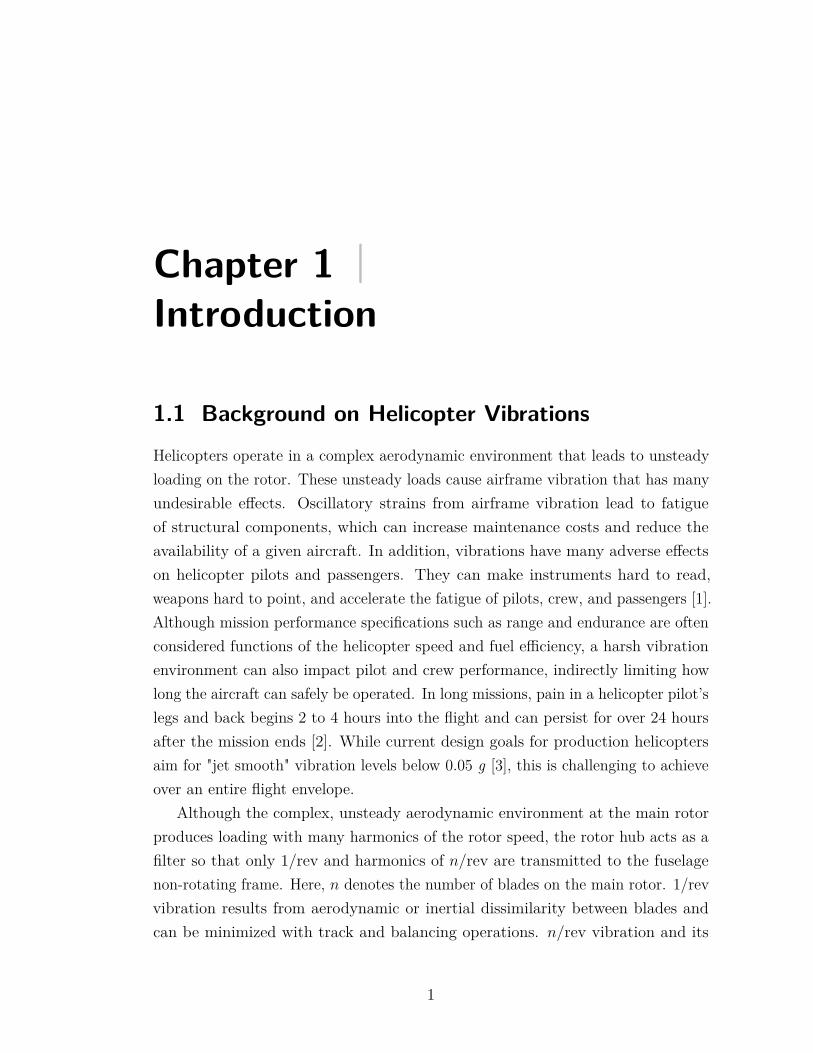
The helicopter tailboom is a long, relatively flexible structure extending fromthe aft end of the fuselage and providing a moment arm for the tail rotor tocontrol the helicopter yaw motion. Because helicopter tailbooms have low inherentstructural damping in the range of 1-2% critical, they are prone to both highresonant amplitudes of vibration and slowly decaying transients. The tailboomand its aerodynamic surfaces are often excited by the main rotor wake, as shownin Figure 1.1. In forward flight, the main rotor wake vortices may impinge onthe horizontal and vertical tail surfaces to cause n/rev vibration in the tailboom,which is transmitted into the fuselage [3]. Even with modern computationaltools, interactional aerodynamics between the main rotor, hub, fuselage, andtailboom aerodynamic surfaces remain difficult to predict before flight testing ofa new helicopter. Examples of helicopters that experienced problems related tointeractional aerodynamics during early flight testing include the EH101, Comanche,and NH90 [5].
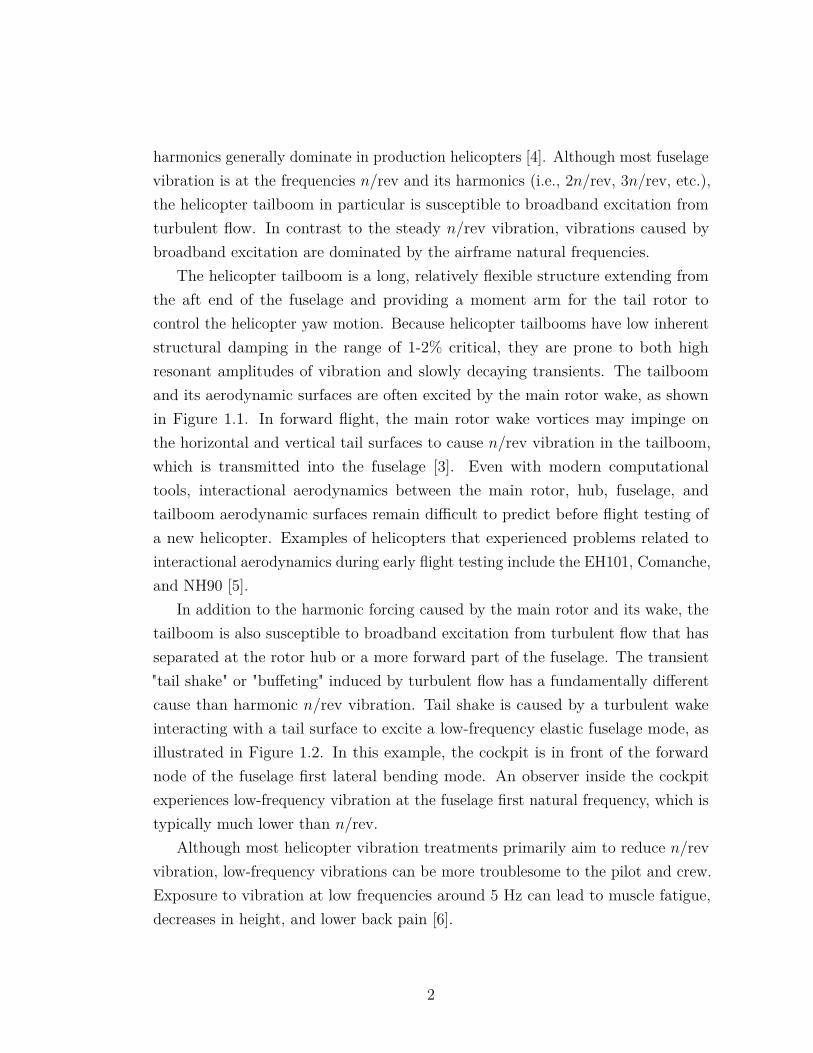
In addition to the harmonic forcing caused by the main rotor and its wake, thetailboom is also susceptible to broadband excitation from turbulent flow that hasseparated at the rotor hub or a more forward part of the fuselage. The transient"tail shake" or "buffeting" induced by turbulent flow has a fundamentally differentcause than harmonic n/rev vibration. Tail shake is caused by a turbulent wakeinteracting with a tail surface to excite a low-frequency elastic fuselage mode, asillustrated in Figure 1.2. In this example, the cockpit is in front of the forwardnode of the fuselage first lateral bending mode. An observer inside the cockpitexperiences low-frequency vibration at the fuselage first natural frequency, which istypically much lower than n/rev.
Although most helicopter vibration treatments primarily aim to reduce n/revvibration, low-frequency vibrations can be more troublesome to the pilot and crew.Exposure to vibration at low frequencies around 5 Hz can lead to muscle fatigue,decreases in height, and lower back pain [6].
2
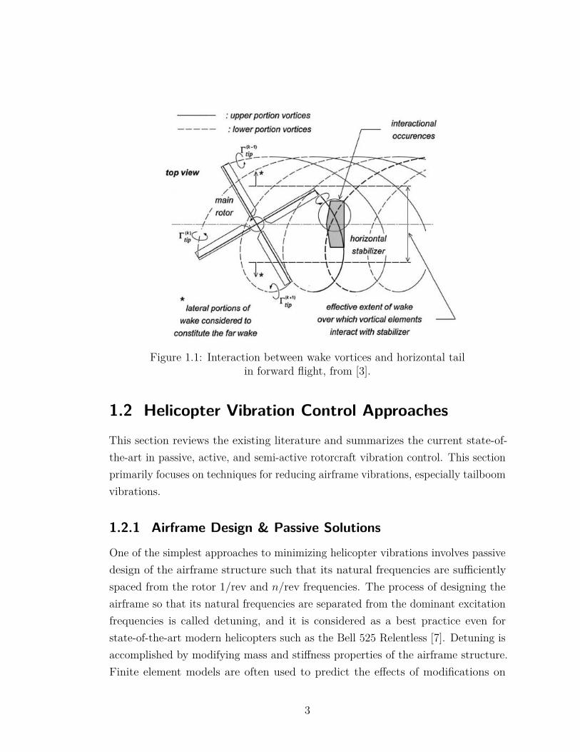
Figure 1.1: Interaction between wake vortices and horizontal tailin forward flight, from [3].
1.2 Helicopter Vibration Control ApproachesThis section reviews the existing literature and summarizes the current state-of-the-art in passive, active, and semi-active rotorcraft vibration control. This sectionprimarily focuses on techniques for reducing airframe vibrations, especially tailboomvibrations.
1.2.1 Airframe Design & Passive Solutions
One of the simplest approaches to minimizing helicopter vibrations involves passivedesign of the airframe structure such that its natural frequencies are sufficientlyspaced from the rotor 1/rev and n/rev frequencies. The process of designing theairframe so that its natural frequencies are separated from the dominant excitationfrequencies is called detuning, and it is considered as a best practice even forstate-of-the-art modern helicopters such as the Bell 525 Relentless [7]. Detuning isaccomplished by modifying mass and stiffness properties of the airframe structure.Finite element models are often used to predict the effects of modifications on
3
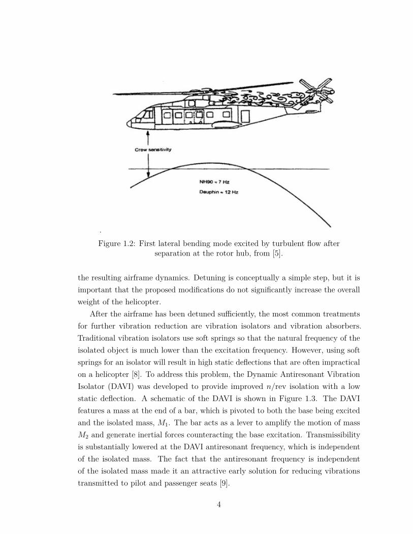
.Figure 1.2: First lateral bending mode excited by turbulent flow after
separation at the rotor hub, from [5].
the resulting airframe dynamics. Detuning is conceptually a simple step, but it isimportant that the proposed modifications do not significantly increase the overallweight of the helicopter.
After the airframe has been detuned sufficiently, the most common treatmentsfor further vibration reduction are vibration isolators and vibration absorbers.Traditional vibration isolators use soft springs so that the natural frequency of theisolated object is much lower than the excitation frequency. However, using softsprings for an isolator will result in high static deflections that are often impracticalon a helicopter [8]. To address this problem, the Dynamic Antiresonant VibrationIsolator (DAVI) was developed to provide improved n/rev isolation with a lowstatic deflection. A schematic of the DAVI is shown in Figure 1.3. The DAVIfeatures a mass at the end of a bar, which is pivoted to both the base being excitedand the isolated mass, M1. The bar acts as a lever to amplify the motion of massM2 and generate inertial forces counteracting the base excitation. Transmissibilityis substantially lowered at the DAVI antiresonant frequency, which is independentof the isolated mass. The fact that the antiresonant frequency is independentof the isolated mass made it an attractive early solution for reducing vibrationstransmitted to pilot and passenger seats [9].
4
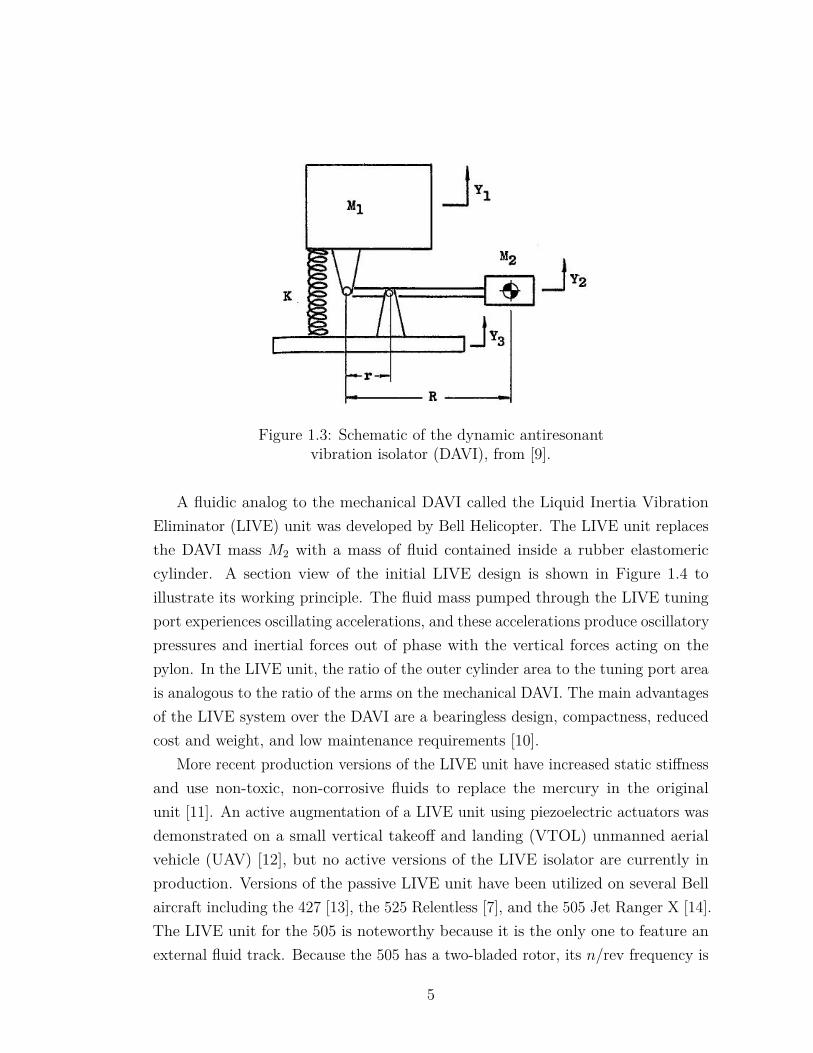
Figure 1.3: Schematic of the dynamic antiresonantvibration isolator (DAVI), from [9].
A fluidic analog to the mechanical DAVI called the Liquid Inertia VibrationEliminator (LIVE) unit was developed by Bell Helicopter. The LIVE unit replacesthe DAVI mass M2 with a mass of fluid contained inside a rubber elastomericcylinder. A section view of the initial LIVE design is shown in Figure 1.4 toillustrate its working principle. The fluid mass pumped through the LIVE tuningport experiences oscillating accelerations, and these accelerations produce oscillatorypressures and inertial forces out of phase with the vertical forces acting on thepylon. In the LIVE unit, the ratio of the outer cylinder area to the tuning port areais analogous to the ratio of the arms on the mechanical DAVI. The main advantagesof the LIVE system over the DAVI are a bearingless design, compactness, reducedcost and weight, and low maintenance requirements [10].
More recent production versions of the LIVE unit have increased static stiffnessand use non-toxic, non-corrosive fluids to replace the mercury in the originalunit [11]. An active augmentation of a LIVE unit using piezoelectric actuators wasdemonstrated on a small vertical takeoff and landing (VTOL) unmanned aerialvehicle (UAV) [12], but no active versions of the LIVE isolator are currently inproduction. Versions of the passive LIVE unit have been utilized on several Bellaircraft including the 427 [13], the 525 Relentless [7], and the 505 Jet Ranger X [14].The LIVE unit for the 505 is noteworthy because it is the only one to feature anexternal fluid track. Because the 505 has a two-bladed rotor, its n/rev frequency is
5
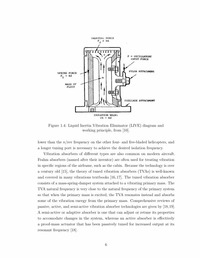
Figure 1.4: Liquid Inertia Vibration Eliminator (LIVE) diagram andworking principle, from [10].
lower than the n/rev frequency on the other four- and five-bladed helicopters, anda longer tuning port is necessary to achieve the desired isolation frequency.
Vibration absorbers of different types are also common on modern aircraft.Frahm absorbers (named after their inventor) are often used for treating vibrationin specific regions of the airframe, such as the cabin. Because the technology is overa century old [15], the theory of tuned vibration absorbers (TVAs) is well-knownand covered in many vibrations textbooks [16,17]. The tuned vibration absorberconsists of a mass-spring-damper system attached to a vibrating primary mass. TheTVA natural frequency is very close to the natural frequency of the primary systemso that when the primary mass is excited, the TVA resonates instead and absorbssome of the vibration energy from the primary mass. Comprehensive reviews ofpassive, active, and semi-active vibration absorber technologies are given by [18,19].A semi-active or adaptive absorber is one that can adjust or retune its propertiesto accomodate changes in the system, whereas an active absorber is effectivelya proof-mass actuator that has been passively tuned for increased output at itsresonant frequency [18].
6
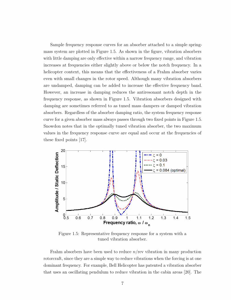
Sample frequency response curves for an absorber attached to a simple spring-mass system are plotted in Figure 1.5. As shown in the figure, vibration absorberswith little damping are only effective within a narrow frequency range, and vibrationincreases at frequencies either slightly above or below the notch frequency. In ahelicopter context, this means that the effectiveness of a Frahm absorber varieseven with small changes in the rotor speed. Although many vibration absorbersare undamped, damping can be added to increase the effective frequency band.However, an increase in damping reduces the antiresonant notch depth in thefrequency response, as shown in Figure 1.5. Vibration absorbers designed withdamping are sometimes referred to as tuned mass dampers or damped vibrationabsorbers. Regardless of the absorber damping ratio, the system frequency responsecurve for a given absorber mass always passes through two fixed points in Figure 1.5.Snowdon notes that in the optimally tuned vibration absorber, the two maximumvalues in the frequency response curve are equal and occur at the frequencies ofthese fixed points [17].
Figure 1.5: Representative frequency response for a system with atuned vibration absorber.
Frahm absorbers have been used to reduce n/rev vibration in many productionrotorcraft, since they are a simple way to reduce vibrations when the forcing is at onedominant frequency. For example, Bell Helicopter has patented a vibration absorberthat uses an oscillating pendulum to reduce vibration in the cabin areas [20]. The
7
pendulum is pivoted about an axis, is attached to a set of springs, and comes intocontact with additional auxiliary springs if its oscillations exceed some design limit.These auxiliary springs ensure that absorber performance is less sensitive to smallvariations in rotor speed. Despite their simplicity, Frahm absorbers are not idealsolutions for reducing rotorcraft vibration because they are not weight-efficient.They are generally most desirable when a mass that is already in the helicopter canbe repurposed as the absorber mass. An example of such repurposing is seen in [21],where Airbus Helicopters engineers propose mounting an aircraft battery inside thehelicopter tailboom on a spring system. The lateral and vertical stiffnesses of thesprings are tuned so that the mass acts as both a lateral and vertical absorber. Thiscould be an effective treatment if a usable mass already exists inside the tailboom.One drawback to this solution is that if the device is retrofitted into an aircraft, itwould alter the helicopter longitudinal center of gravity, since it must be placednear the end of the tailboom to be effective. This center of gravity shift is generallyundesirable because it could reduce aircraft control margins [22]. Space constraintscould also be a factor in the viability of this absorber, since the mass would belocated at the tip of the tailboom, which normally tapers into a small cross-section.A similar device that is also patented by Airbus Helicopters uses a sloshing mass offluid contained between two plates on springs as the absorber mass [23].
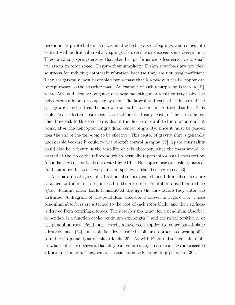
A separate category of vibration absorbers called pendulum absorbers areattached to the main rotor instead of the airframe. Pendulum absorbers reducen/rev dynamic shear loads transmitted through the hub before they enter theairframe. A diagram of the pendulum absorber is shown in Figure 1.6. Thesependulum absorbers are attached to the root of each rotor blade, and their stiffnessis derived from centrifugal forces. The absorber frequency for a pendulum absorber,or pendab, is a function of the pendulum arm length la and the radial position ra ofthe pendulum root. Pendulum absorbers have been applied to reduce out-of-planevibratory loads [24], and a similar device called a bifilar absorber has been appliedto reduce in-plane dynamic shear loads [25]. As with Frahm absorbers, the maindrawback of these devices is that they can require a large mass to achieve appreciablevibration reduction. They can also result in aerodynamic drag penalties [26].
8
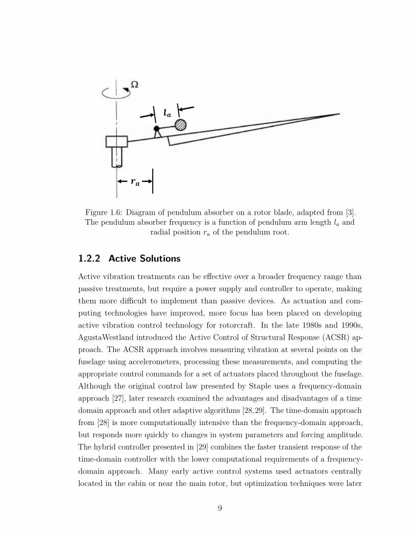
Figure 1.6: Diagram of pendulum absorber on a rotor blade, adapted from [3].The pendulum absorber frequency is a function of pendulum arm length la and
radial position ra of the pendulum root.
1.2.2 Active Solutions
Active vibration treatments can be effective over a broader frequency range thanpassive treatments, but require a power supply and controller to operate, makingthem more difficult to implement than passive devices. As actuation and com-puting technologies have improved, more focus has been placed on developingactive vibration control technology for rotorcraft. In the late 1980s and 1990s,AgustaWestland introduced the Active Control of Structural Response (ACSR) ap-proach. The ACSR approach involves measuring vibration at several points on thefuselage using accelerometers, processing these measurements, and computing theappropriate control commands for a set of actuators placed throughout the fuselage.Although the original control law presented by Staple uses a frequency-domainapproach [27], later research examined the advantages and disadvantages of a timedomain approach and other adaptive algorithms [28,29]. The time-domain approachfrom [28] is more computationally intensive than the frequency-domain approach,but responds more quickly to changes in system parameters and forcing amplitude.The hybrid controller presented in [29] combines the faster transient response of thetime-domain controller with the lower computational requirements of a frequency-domain approach. Many early active control systems used actuators centrallylocated in the cabin or near the main rotor, but optimization techniques were later
9
applied to identify the most effective and efficient actuator locations [30, 31]. Inrecent years, fuselage-based active control research has improved algorithms forcontrolling the actuators [32]. Active control systems have been demonstrated onmany aircraft including the Bell 429 [33] and Eurocopter EC130 and EC135 [34].
In addition to fuselage treatments, active isolators have been developed tofurther reduce the transmission of forces and moments through the rotor hub.Panza, McGuire, and Jones add an actuator controlled by pressure feedback to apassive fluidic isolator [35]. This results in greater isolation over a wider frequencyrange than the passive device, and it also improves the robustness of the isolatorto parameter variations such as those caused by temperature changes. Similarly,Airbus developed an active version of the DAVI using electromagnetic actuators todrive the motion of flapping masses attached to the main gearbox. This active deviceimproves isolation at the n/rev frequency and provides more effective isolationacross a wider frequency range than a passive device [36]. Bell Helicopter haspatented a version of the LIVE unit in which pistons can be actively controlled tomove fluid through the tuning port at a desired frequency [37]. Another isolatordeveloped by Sikorsky and LORD Corporation called the Hub-Mounted VibrationSuppressor (HMVS) uses motor-driven rotating eccentric masses to cancel 4/revin-plane vibratory hub loads [38]. The HMVS was ground tested in tandem with afuselage active vibration control system that reduces the remaining vertical hubloads, and it has also been flight tested on a UH-60A helicopter to demonstratevibration reduction similar to or better than the previously implemented 4/revvibration absorbers inside the airframe [39]. The authors claim that the HMVS saves40 pounds of weight compared to the bifilar absorbers installed on the productionUH-60A.
A number of active solutions have been developed specifically to target andreduce helicopter tailboom vibrations. Krysinsky patented the concept of activelycontrolling tail rotor blade pitch to generate forces opposing low-frequency lateraltailboom vibration [40]. Alternatively, Eglin suggests generating control forcesby actively controlling the incidence angle of tail surfaces or flaps attached tothe tail surfaces [41]. This avoids the increased noise and accelerated componentfatigue associated with controlling tail rotor pitch. Manfredotti patented an activeabsorber using a mass attached to a flexible beam, the motion of which can becontrolled and amplified by electromagnetic forces [42]. This device is unique
10
because although it is active, it has no moving parts. Strehlow et al. describe bothpassive and active tailboom damping devices that use the sensing and actuationcapabilities of piezoelectric materials [43]. Klöppel et al. suggest using activemain rotor controls such as trailing edge flaps, twist, and speed control to generateactuation forces opposing vibration [44]. Even the Zero-VibeTM system using theHMVS and circular force generators above the cabin had dedicated actuators fortailboom vibration control. Because it was only designed to eliminate vibratoryloads entering the airframe through the main rotor pylon, additional actuatorswere required on the tail to eliminate vibrations caused by the main rotor wakeimpinging on the tail [45].
Although active rotors have been studied for decades and show promise forvibration and noise reduction, no production helicopters make use of higher harmoniccontrol (HHC), individual blade control (IBC), or any other active rotor technology.This is largely due to the complexity of integrating such a system and the reliabilityrequirements that must be met for production helicopters [46].
1.2.3 Semi-Active Solutions
As with active treatments, semi-active treatments require controllers and actuators,but involve adjusting one or more parameters (i.e., stiffness, mass, or damping) ofan otherwise passive device. Because the active aspect is only used for parameteradjustment and not for continuously generating forces, power and actuation re-quirements are often less demanding for semi-active treatments than for fully activetreatments. Semi-active solutions are especially attractive for helicopter applica-tions, since the ability to vary rotor speed (and therefore, the n/rev frequency) canoptimize performance for different flight conditions. While a passive tuned solutionmight only effectively treat vibrations at one rotor speed, a semi-active solutioncan be re-tuned so that it remains effective at a different rotor speed.
Several researchers have demonstrated semi-active versions of the Liquid InertiaVibration Eliminator concept. Cronjé et al. use variable stiffness circular leafsprings attached to rolling diaphragms to move fluid inside the isolator [47]. duPlooy et al. modified the basic LIVE design by adding a flexible rubber membraneto separate the fluid reservoirs from adjustible pneumatic springs. The isolationfrequency of this "tunable vibration absorbing isolator" can be controlled by adjust-
11
ing the pressure of the pneumatic springs [48]. Bell Helicopter has also patentedmodifications to its initial LIVE device, such as one with a tuning port that canbe axially extended by a motor [49]. Another fluid-based semi-active isolator usesmagnetorheological (MR) fluid to provide vibration isolation for crew seats whilepreserving the crashworthiness of traditional seats [50].
A number of airframe-based semi-active solutions can be found in the literature.Bansemir developed a vibration absorber using a cantilever beam with a mass at theend [51]. The resonant frequency of the absorber can be adjusted by either varyinghow much of the beam is clamped at the root end or by increasing the pre-tensionof nonlinear springs attached to the beam. du Bois et al. suggest varying the loadcarried by structural members and using stress-stiffening effects to shift naturalfrequencies of a structure in real time [52]. du Bois et al. also developed a semi-activeabsorber using the distributed mass of a cable as the absorber mass [53]. Adjustingthe cable tension changes the cable resonant frequency, thereby introducing a tuningmechanism for the device.
1.3 Rotor Blade DampersMost helicopters require lead-lag dampers on the main rotor to ensure that theyremain free of aeromechanical instabilities such as ground or air resonance. Bladedrag contributes little aerodynamic damping, so discrete lead-lag dampers arerequired to augment the stability of almost all articulated rotors. However, lead-lagdampers are complex parts that increase the maintenance time and cost associatedwith operating the helicopter. Effective lead-lag dampers that provide high dampingwith minimal required maintenance have been a long-standing need of the rotorcraftindustry.
Most main rotor dampers are either elastomeric or hydraulic components.Examples of these two types of dampers are shown in Figure 1.7. Each of theseoptions have their own unique advantages and disadvantages. Elastomeric dampersare typically stiffer and may contribute less damping than hydraulic dampers, butthey often require less maintenance because of their simplicity [54]. Conversely,a hydraulic damper may be necessary if an elastomeric damper will not providesufficient damping. The presence of sliding seals in hydraulic dampers that canwear out and leak, however, is a significant drawback [55]. A third class of lead-lag
12
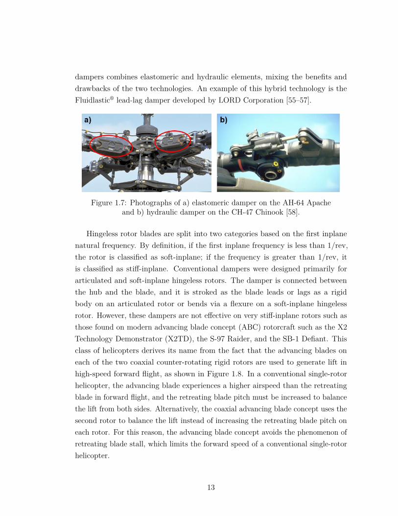
dampers combines elastomeric and hydraulic elements, mixing the benefits anddrawbacks of the two technologies. An example of this hybrid technology is theFluidlastic® lead-lag damper developed by LORD Corporation [55–57].
Figure 1.7: Photographs of a) elastomeric damper on the AH-64 Apacheand b) hydraulic damper on the CH-47 Chinook [58].
Hingeless rotor blades are split into two categories based on the first inplanenatural frequency. By definition, if the first inplane frequency is less than 1/rev,the rotor is classified as soft-inplane; if the frequency is greater than 1/rev, itis classified as stiff-inplane. Conventional dampers were designed primarily forarticulated and soft-inplane hingeless rotors. The damper is connected betweenthe hub and the blade, and it is stroked as the blade leads or lags as a rigidbody on an articulated rotor or bends via a flexure on a soft-inplane hingelessrotor. However, these dampers are not effective on very stiff-inplane rotors such asthose found on modern advancing blade concept (ABC) rotorcraft such as the X2Technology Demonstrator (X2TD), the S-97 Raider, and the SB-1 Defiant. Thisclass of helicopters derives its name from the fact that the advancing blades oneach of the two coaxial counter-rotating rigid rotors are used to generate lift inhigh-speed forward flight, as shown in Figure 1.8. In a conventional single-rotorhelicopter, the advancing blade experiences a higher airspeed than the retreatingblade in forward flight, and the retreating blade pitch must be increased to balancethe lift from both sides. Alternatively, the coaxial advancing blade concept uses thesecond rotor to balance the lift instead of increasing the retreating blade pitch oneach rotor. For this reason, the advancing blade concept avoids the phenomenon ofretreating blade stall, which limits the forward speed of a conventional single-rotorhelicopter.
13
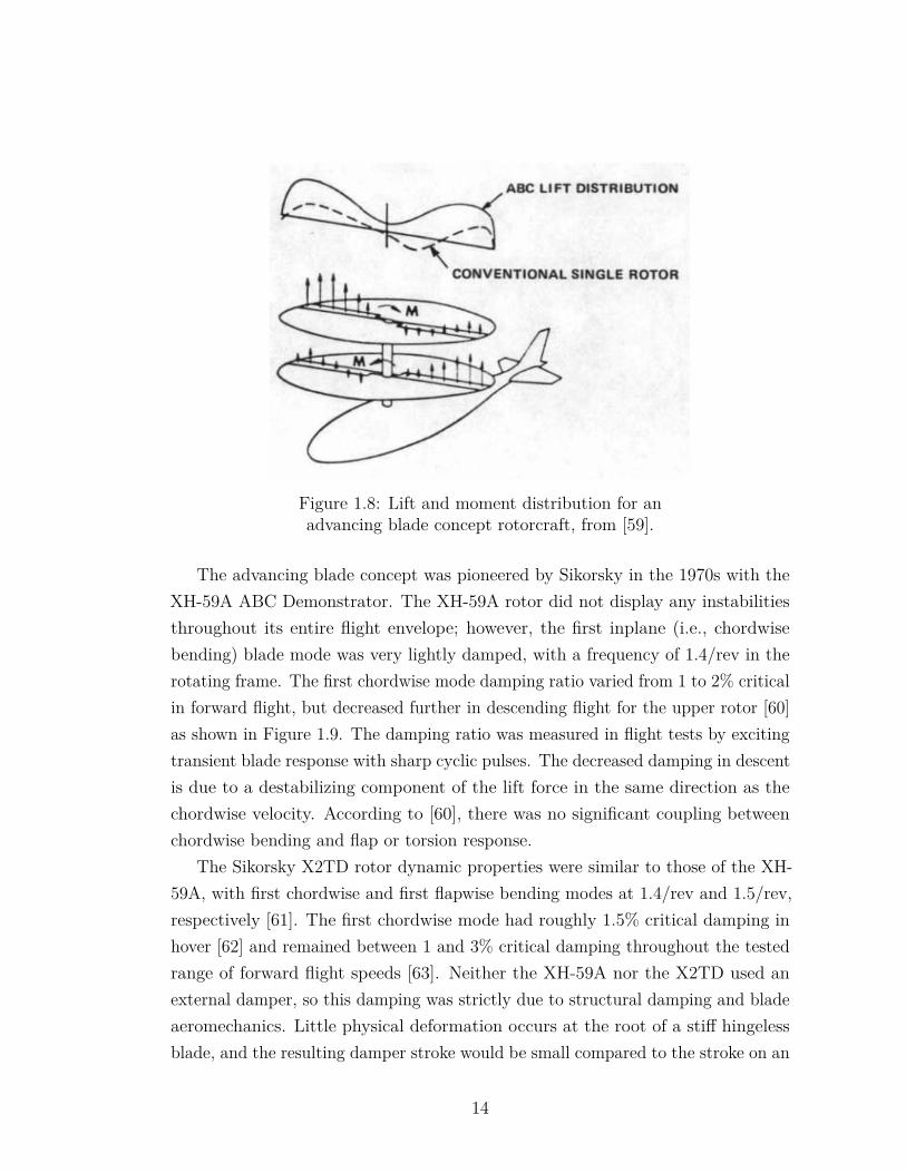
Figure 1.8: Lift and moment distribution for anadvancing blade concept rotorcraft, from [59].
The advancing blade concept was pioneered by Sikorsky in the 1970s with theXH-59A ABC Demonstrator. The XH-59A rotor did not display any instabilitiesthroughout its entire flight envelope; however, the first inplane (i.e., chordwisebending) blade mode was very lightly damped, with a frequency of 1.4/rev in therotating frame. The first chordwise mode damping ratio varied from 1 to 2% criticalin forward flight, but decreased further in descending flight for the upper rotor [60]as shown in Figure 1.9. The damping ratio was measured in flight tests by excitingtransient blade response with sharp cyclic pulses. The decreased damping in descentis due to a destabilizing component of the lift force in the same direction as thechordwise velocity. According to [60], there was no significant coupling betweenchordwise bending and flap or torsion response.
The Sikorsky X2TD rotor dynamic properties were similar to those of the XH-59A, with first chordwise and first flapwise bending modes at 1.4/rev and 1.5/rev,respectively [61]. The first chordwise mode had roughly 1.5% critical damping inhover [62] and remained between 1 and 3% critical damping throughout the testedrange of forward flight speeds [63]. Neither the XH-59A nor the X2TD used anexternal damper, so this damping was strictly due to structural damping and bladeaeromechanics. Little physical deformation occurs at the root of a stiff hingelessblade, and the resulting damper stroke would be small compared to the stroke on an
14
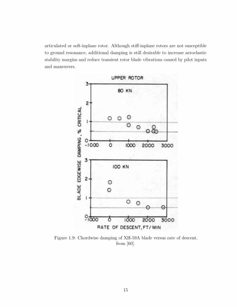
articulated or soft-inplane rotor. Although stiff-inplane rotors are not susceptibleto ground resonance, additional damping is still desirable to increase aeroelasticstability margins and reduce transient rotor blade vibrations caused by pilot inputsand maneuvers.
Figure 1.9: Chordwise damping of XH-59A blade versus rate of descent,from [60].
15
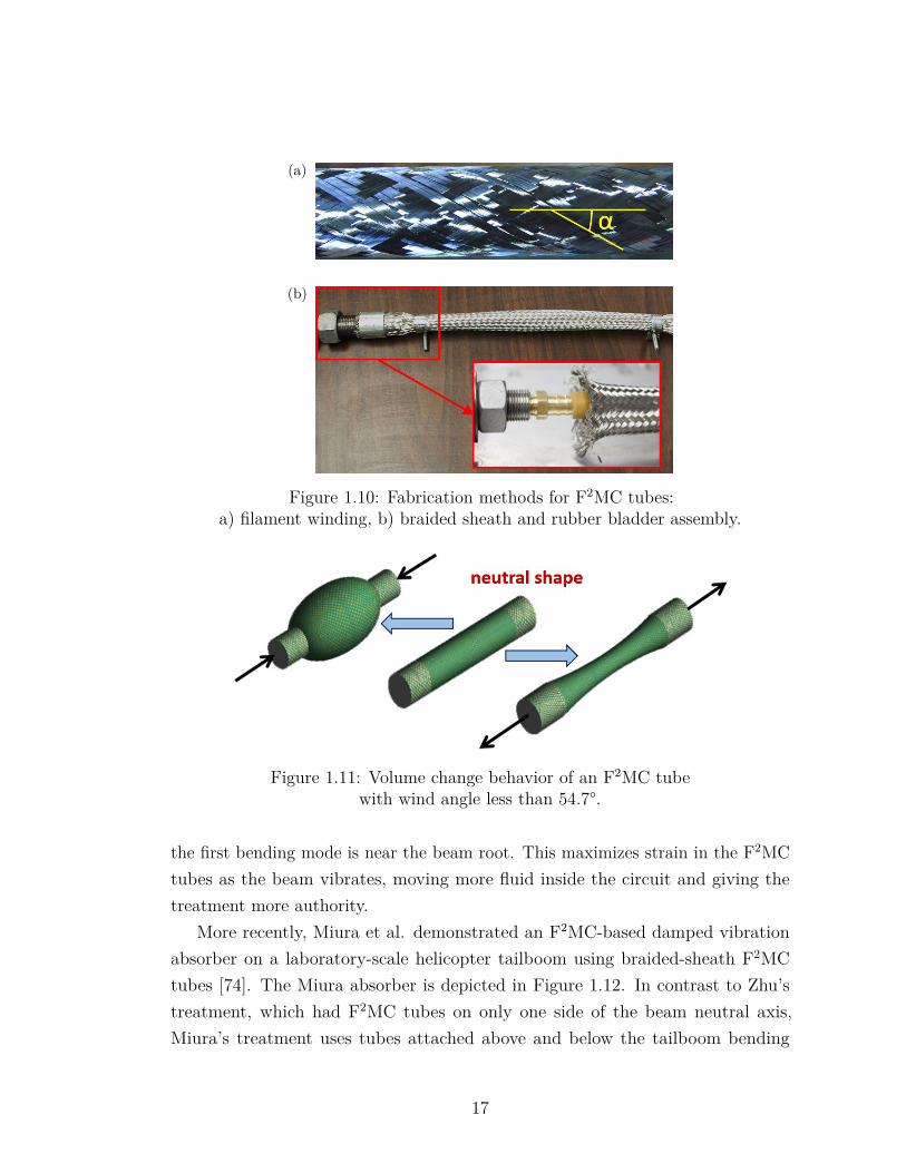
1.4 Fluidic Flexible Matrix Composite TubesFluidic Flexible Matrix Composite (F2MC) tubes are an emerging technology withthe ability to provide lightweight and compact vibration control for aerospacestructures. Two fabrication methods for F2MC tubes are illustrated in Figure 1.10.F2MC tubes can be made either by using composite processing methods such asfilament winding or by assembling a braided fiber sheath over a rubber bladder. Ineither fabrication method, a set of interlocking fibers, which are much stiffer thaneither the matrix material or the rubber bladder, reinforce the tube and form windangle α with respect to the longitudinal axis. F2MC tubes are functionally similarto pneumatic McKibben actuators, which contract axially when pressurized if thefiber angle is less than 54.7° and extend axially when pressurized if the fiber angleis greater than 54.7° [64]. Accordingly, F2MC tubes with wind angle less than 54.7°are referred to as contractor tubes, and tubes with wind angle greater than 54.7°are referred to as extender tubes.
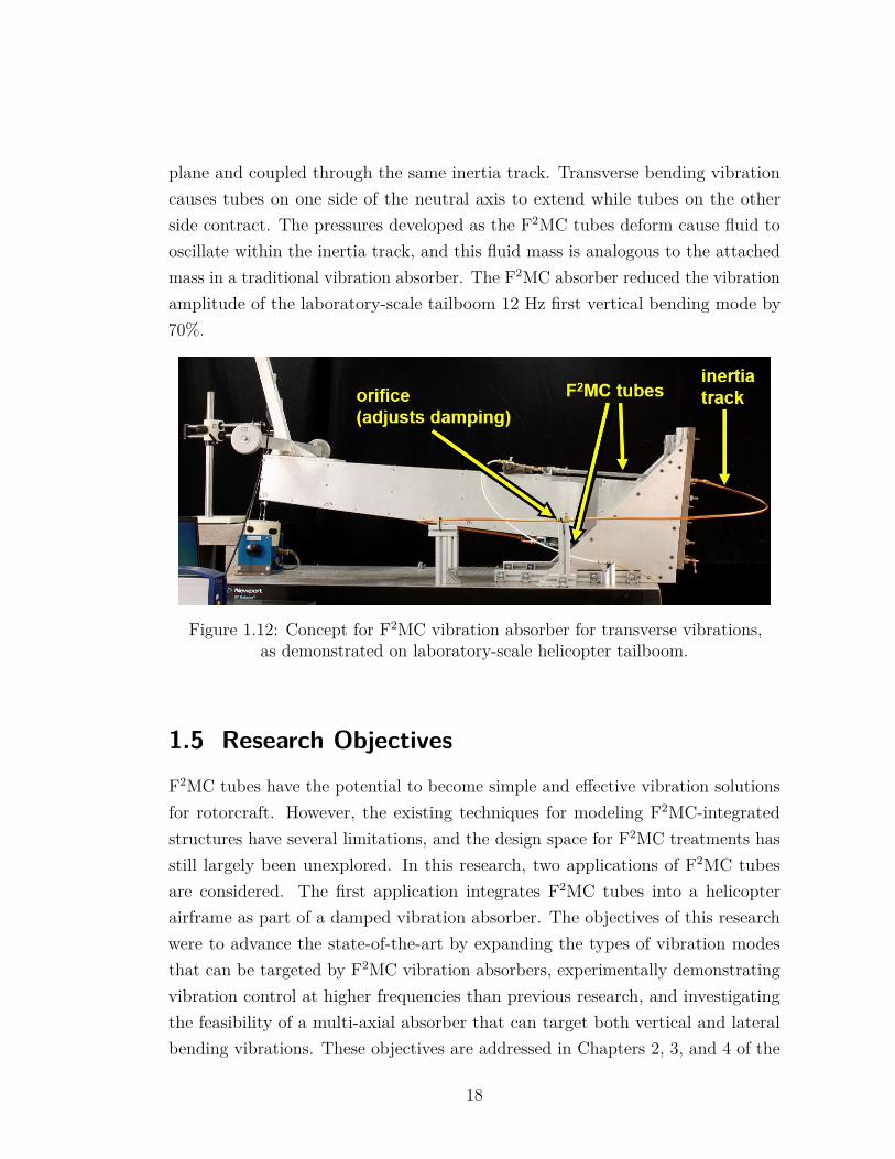
Filament wound F2MC tubes can be modeled using the Lekhnitskii solution foran orthotropic cylinder under axial and pressure loading [65] as in [66,67], whilethere are examples of both linear [68] and nonlinear [64, 69] models for braided-sheath tubes. With proper tailoring of the fiber angle, F2MC tubes exhibit highvolume change when strained axially as shown in Figure 1.11, and are capable ofmoving fluid 1-2 orders of magnitude more efficiently than a piston of the samediameter [70]. The enhanced pumping and actuation capabilities of F2MC tubesmake it possible for a small amount of actual fluid mass in the circuit to have ahigh effective inertia.
Early research showed that coupling F2MC tubes with a fluidic circuit canachieve vibration control effects such as isolation [68] and absorption [71] in lumpedparameter systems. Zhu et al. were the first to integrate F2MC tubes into acontinuous structure for vibration control, experimentally demonstrating bothdamping [72] and vibration absorption [73] on a small-scale cantilever beam. TheF2MC tubes in Zhu’s experiments were fabricated by embedding stainless steelfibers in a polyurethane matrix. The axial forces exerted by the F2MC tubes aretransmitted into the beam through attachment brackets, resulting in a net momentat the beam root that counteracts the external forcing. Zhu et al. also made thekey conclusion that the optimal placement for F2MC tubes in a treatment targeting
16
(a)
(b)
Figure 1.10: Fabrication methods for F2MC tubes:a) filament winding, b) braided sheath and rubber bladder assembly.
Figure 1.11: Volume change behavior of an F2MC tubewith wind angle less than 54.7°.
the first bending mode is near the beam root. This maximizes strain in the F2MCtubes as the beam vibrates, moving more fluid inside the circuit and giving thetreatment more authority.
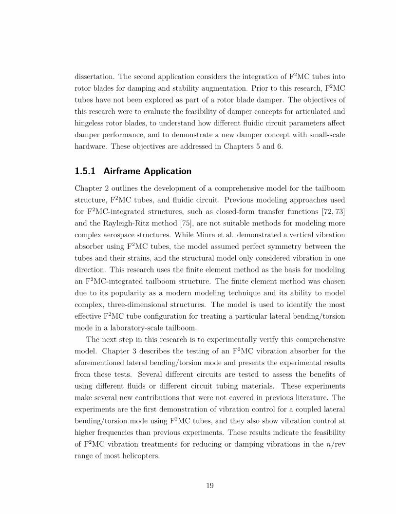
More recently, Miura et al. demonstrated an F2MC-based damped vibrationabsorber on a laboratory-scale helicopter tailboom using braided-sheath F2MCtubes [74]. The Miura absorber is depicted in Figure 1.12. In contrast to Zhu’streatment, which had F2MC tubes on only one side of the beam neutral axis,Miura’s treatment uses tubes attached above and below the tailboom bending
17
plane and coupled through the same inertia track. Transverse bending vibrationcauses tubes on one side of the neutral axis to extend while tubes on the otherside contract. The pressures developed as the F2MC tubes deform cause fluid tooscillate within the inertia track, and this fluid mass is analogous to the attachedmass in a traditional vibration absorber. The F2MC absorber reduced the vibrationamplitude of the laboratory-scale tailboom 12 Hz first vertical bending mode by70%.
Figure 1.12: Concept for F2MC vibration absorber for transverse vibrations,as demonstrated on laboratory-scale helicopter tailboom.
1.5 Research ObjectivesF2MC tubes have the potential to become simple and effective vibration solutionsfor rotorcraft. However, the existing techniques for modeling F2MC-integratedstructures have several limitations, and the design space for F2MC treatments hasstill largely been unexplored. In this research, two applications of F2MC tubesare considered. The first application integrates F2MC tubes into a helicopterairframe as part of a damped vibration absorber. The objectives of this researchwere to advance the state-of-the-art by expanding the types of vibration modesthat can be targeted by F2MC vibration absorbers, experimentally demonstratingvibration control at higher frequencies than previous research, and investigatingthe feasibility of a multi-axial absorber that can target both vertical and lateralbending vibrations. These objectives are addressed in Chapters 2, 3, and 4 of the
18
dissertation. The second application considers the integration of F2MC tubes intorotor blades for damping and stability augmentation. Prior to this research, F2MCtubes have not been explored as part of a rotor blade damper. The objectives ofthis research were to evaluate the feasibility of damper concepts for articulated andhingeless rotor blades, to understand how different fluidic circuit parameters affectdamper performance, and to demonstrate a new damper concept with small-scalehardware. These objectives are addressed in Chapters 5 and 6.
1.5.1 Airframe Application
Chapter 2 outlines the development of a comprehensive model for the tailboomstructure, F2MC tubes, and fluidic circuit. Previous modeling approaches usedfor F2MC-integrated structures, such as closed-form transfer functions [72, 73]and the Rayleigh-Ritz method [75], are not suitable methods for modeling morecomplex aerospace structures. While Miura et al. demonstrated a vertical vibrationabsorber using F2MC tubes, the model assumed perfect symmetry between thetubes and their strains, and the structural model only considered vibration in onedirection. This research uses the finite element method as the basis for modelingan F2MC-integrated tailboom structure. The finite element method was chosendue to its popularity as a modern modeling technique and its ability to modelcomplex, three-dimensional structures. The model is used to identify the mosteffective F2MC tube configuration for treating a particular lateral bending/torsionmode in a laboratory-scale tailboom.
The next step in this research is to experimentally verify this comprehensivemodel. Chapter 3 describes the testing of an F2MC vibration absorber for theaforementioned lateral bending/torsion mode and presents the experimental resultsfrom these tests. Several different circuits are tested to assess the benefits ofusing different fluids or different circuit tubing materials. These experimentsmake several new contributions that were not covered in previous literature. Theexperiments are the first demonstration of vibration control for a coupled lateralbending/torsion mode using F2MC tubes, and they also show vibration control athigher frequencies than previous experiments. These results indicate the feasibilityof F2MC vibration treatments for reducing or damping vibrations in the n/revrange of most helicopters.
19
Two additional advantages of the new structural modeling approach are that thefinite element model is three-dimensional and all of the fluidic circuit dynamics areexplicitly modeled. In previous research studying F2MC-integrated structures, thebeam was treated as one-dimensional along its length, and equivalent fluidic circuitproperties were chosen for the model based on the assumed direction of vibration.The new model makes it possible to consider how a single F2MC treatment affectsvibrations in both lateral and vertical directions. Chapter 4 covers the design andexperimental demonstration of a new F2MC vibration treatment that can treatvibrations in one lateral and one vertical mode with the same fluidic circuit. Thisis accomplished with a more thorough design of the inertia track, although thereare no fundamental differences between this fluidic circuit concept and the conceptpreviously used to reduce tailboom lateral bending and torsional vibrations.
1.5.2 Rotor Blade Application
Chapter 5 analyzes two different F2MC damper concepts for full-scale articulatedand hingeless rotor blades. The feasibility of each concept is investigated bydeveloping a model for the in-plane dynamics of a full-scale rotor blade that hasbeen integrated with the corresponding F2MC device. Rotor blades based onthe UH-60 blade, the X2 blade, and the BO105 blade are used as representativearticulated, stiff-inplane, and soft-inplane blades, respectively. These models areused to guide the preliminary design of F2MC dampers for each type of rotor, toassess the effectiveness of these dampers, and to understand the influence of keyfluidic circuit parameters.
The final goal of this research is to build and test a small-scale prototypearticulated blade F2MC damper to demonstrate the concept analyzed in Chapter5 and identify physical challenges with its implementation. Chapter 6 covers thedesign, implementation, and benchtop testing of this F2MC damper. Springs areused to simulate an effective rotational stiffness, and both frequency- and time-domain tests are conducted to characterize the damper performance. This benchtopprototyping and testing paves the way for future rotating demonstrations of F2MCblade damper technology.
20
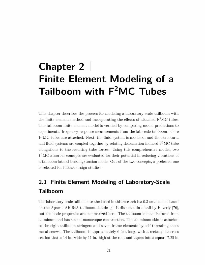
Chapter 2 |Finite Element Modeling of aTailboom with F2MC Tubes
This chapter describes the process for modeling a laboratory-scale tailboom withthe finite element method and incorporating the effects of attached F2MC tubes.The tailboom finite element model is verified by comparing model predictions toexperimental frequency response measurements from the lab-scale tailboom beforeF2MC tubes are attached. Next, the fluid system is modeled, and the structuraland fluid systems are coupled together by relating deformation-induced F2MC tubeelongations to the resulting tube forces. Using this comprehensive model, twoF2MC absorber concepts are evaluated for their potential in reducing vibrations ofa tailboom lateral bending/torsion mode. Out of the two concepts, a preferred oneis selected for further design studies.
2.1 Finite Element Modeling of Laboratory-ScaleTailboomThe laboratory-scale tailboom testbed used in this research is a 0.3-scale model basedon the Apache AH-64A tailboom. Its design is discussed in detail by Heverly [76],but the basic properties are summarized here. The tailboom is manufactured fromaluminum and has a semi-monocoque construction. The aluminum skin is attachedto the eight tailboom stringers and seven frame elements by self-threading sheetmetal screws. The tailboom is approximately 6 feet long, with a rectangular crosssection that is 14 in. wide by 11 in. high at the root and tapers into a square 7.25 in.
21
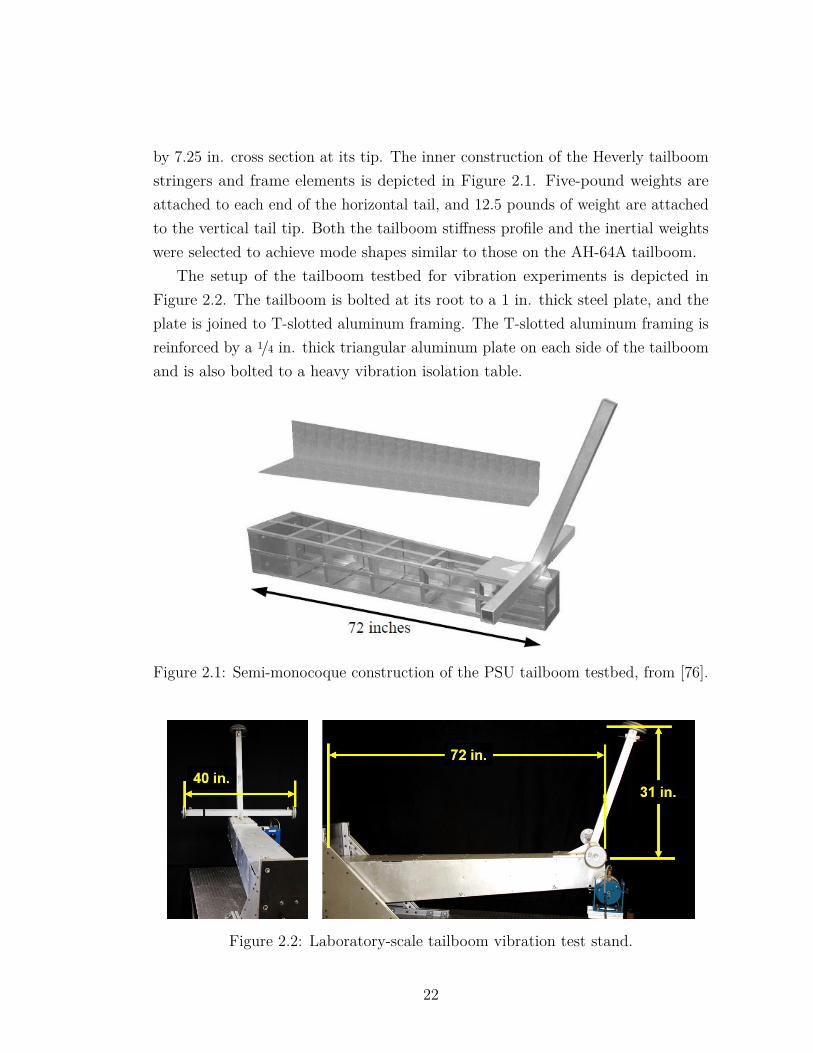
by 7.25 in. cross section at its tip. The inner construction of the Heverly tailboomstringers and frame elements is depicted in Figure 2.1. Five-pound weights areattached to each end of the horizontal tail, and 12.5 pounds of weight are attachedto the vertical tail tip. Both the tailboom stiffness profile and the inertial weightswere selected to achieve mode shapes similar to those on the AH-64A tailboom.
The setup of the tailboom testbed for vibration experiments is depicted inFigure 2.2. The tailboom is bolted at its root to a 1 in. thick steel plate, and theplate is joined to T-slotted aluminum framing. The T-slotted aluminum framing isreinforced by a 1/4 in. thick triangular aluminum plate on each side of the tailboomand is also bolted to a heavy vibration isolation table.
Figure 2.1: Semi-monocoque construction of the PSU tailboom testbed, from [76].
Figure 2.2: Laboratory-scale tailboom vibration test stand.
22
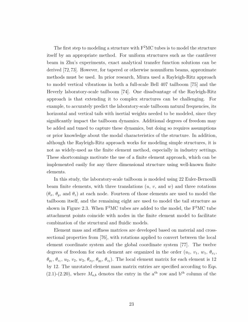
The first step to modeling a structure with F2MC tubes is to model the structureitself by an appropriate method. For uniform structures such as the cantileverbeam in Zhu’s experiments, exact analytical transfer function solutions can bederived [72,73]. However, for tapered or otherwise nonuniform beams, approximatemethods must be used. In prior research, Miura used a Rayleigh-Ritz approachto model vertical vibrations in both a full-scale Bell 407 tailboom [75] and theHeverly laboratory-scale tailboom [74]. One disadvantage of the Rayleigh-Ritzapproach is that extending it to complex structures can be challenging. Forexample, to accurately predict the laboratory-scale tailboom natural frequencies, itshorizontal and vertical tails with inertial weights needed to be modeled, since theysignificantly impact the tailboom dynamics. Additional degrees of freedom maybe added and tuned to capture these dynamics, but doing so requires assumptionsor prior knowledge about the modal characteristics of the structure. In addition,although the Rayleigh-Ritz approach works for modeling simple structures, it isnot as widely-used as the finite element method, especially in industry settings.These shortcomings motivate the use of a finite element approach, which can beimplemented easily for any three dimensional structure using well-known finiteelements.
In this study, the laboratory-scale tailboom is modeled using 22 Euler-Bernoullibeam finite elements, with three translations (u, v, and w) and three rotations(θx, θy, and θz) at each node. Fourteen of those elements are used to model thetailboom itself, and the remaining eight are used to model the tail structure asshown in Figure 2.3. When F2MC tubes are added to the model, the F2MC tubeattachment points coincide with nodes in the finite element model to facilitatecombination of the structural and fluidic models.
Element mass and stiffness matrices are developed based on material and cross-sectional properties from [76], with rotations applied to convert between the localelement coordinate system and the global coordinate system [77]. The twelvedegrees of freedom for each element are organized in the order (u1, v1, w1, θx1 ,θy1 , θz1 , u2, v2, w2, θx2 , θy2 , θz2). The local element matrix for each element is 12by 12. The unrotated element mass matrix entries are specified according to Eqs.(2.1)-(2.20), where Ma,b denotes the entry in the ath row and bth column of the
23
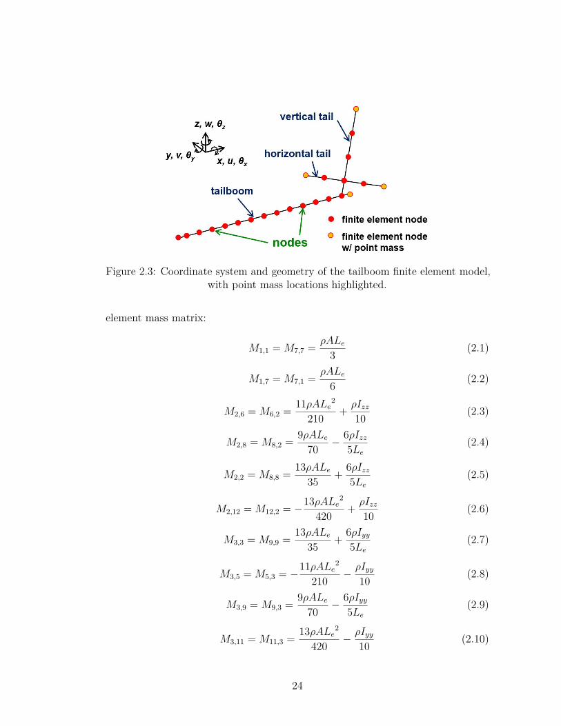
Figure 2.3: Coordinate system and geometry of the tailboom finite element model,with point mass locations highlighted.
element mass matrix:
M1,1 = M7,7 = ρALe3 (2.1)
M1,7 = M7,1 = ρALe6 (2.2)
M2,6 = M6,2 = 11ρALe2
210 + ρIzz10 (2.3)
M2,8 = M8,2 = 9ρALe70 − 6ρIzz
5Le(2.4)
M2,2 = M8,8 = 13ρALe35 + 6ρIzz
5Le(2.5)
M2,12 = M12,2 = −13ρALe2
420 + ρIzz10 (2.6)
M3,3 = M9,9 = 13ρALe35 + 6ρIyy
5Le(2.7)
M3,5 = M5,3 = −11ρALe2
210 − ρIyy10 (2.8)
M3,9 = M9,3 = 9ρALe70 − 6ρIyy
5Le(2.9)
M3,11 = M11,3 = 13ρALe2
420 − ρIyy10 (2.10)
24
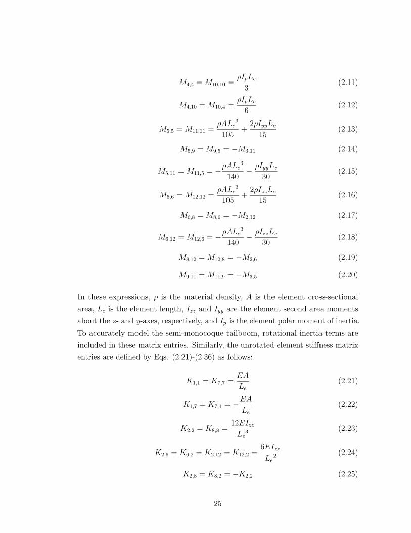
M4,4 = M10,10 = ρIpLe3 (2.11)
M4,10 = M10,4 = ρIpLe6 (2.12)
M5,5 = M11,11 = ρALe3
105 + 2ρIyyLe15 (2.13)
M5,9 = M9,5 = −M3,11 (2.14)
M5,11 = M11,5 = −ρALe3
140 − ρIyyLe30 (2.15)
M6,6 = M12,12 = ρALe3
105 + 2ρIzzLe15 (2.16)
M6,8 = M8,6 = −M2,12 (2.17)
M6,12 = M12,6 = −ρALe3
140 − ρIzzLe30 (2.18)
M8,12 = M12,8 = −M2,6 (2.19)
M9,11 = M11,9 = −M3,5 (2.20)
In these expressions, ρ is the material density, A is the element cross-sectionalarea, Le is the element length, Izz and Iyy are the element second area momentsabout the z- and y-axes, respectively, and Ip is the element polar moment of inertia.To accurately model the semi-monocoque tailboom, rotational inertia terms areincluded in these matrix entries. Similarly, the unrotated element stiffness matrixentries are defined by Eqs. (2.21)-(2.36) as follows:
K1,1 = K7,7 = EA
Le(2.21)
K1,7 = K7,1 = −EALe
(2.22)
K2,2 = K8,8 = 12EIzzLe
3 (2.23)
K2,6 = K6,2 = K2,12 = K12,2 = 6EIzzLe
2 (2.24)
K2,8 = K8,2 = −K2,2 (2.25)
25
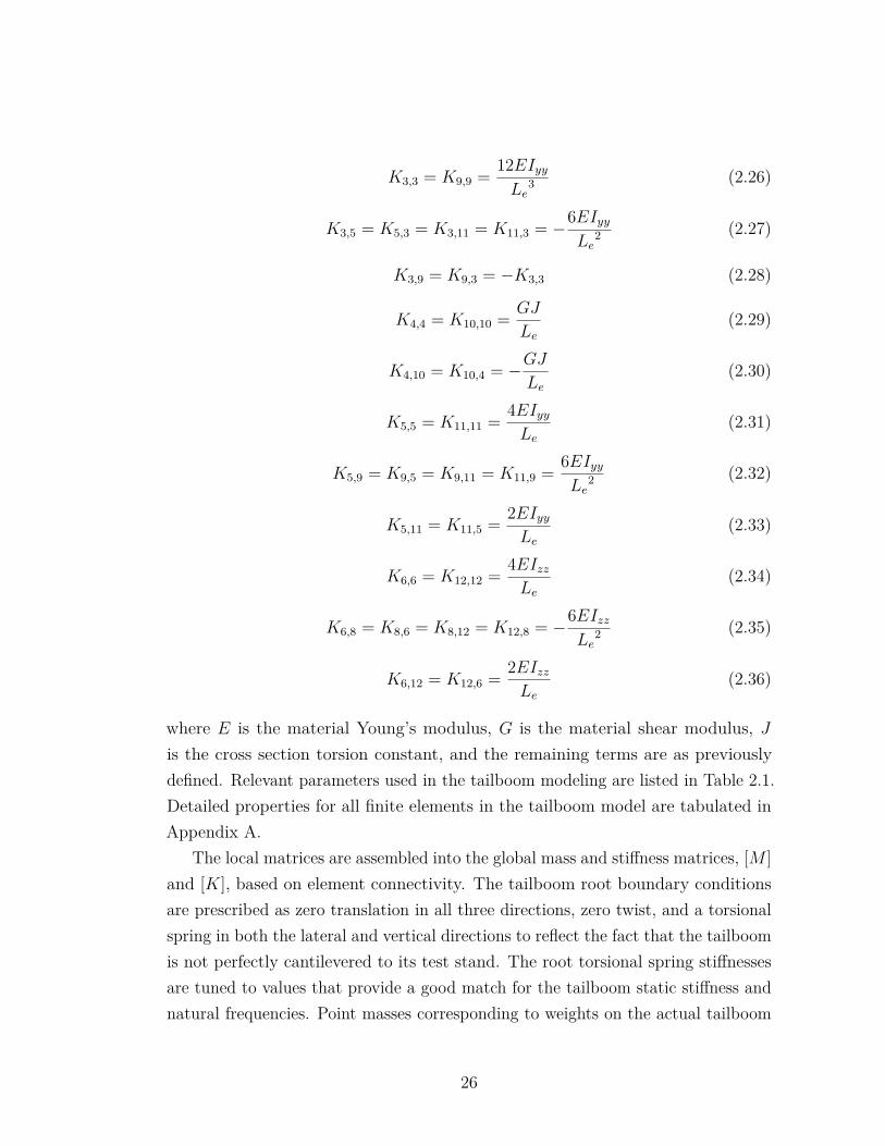
K3,3 = K9,9 = 12EIyyLe
3 (2.26)
K3,5 = K5,3 = K3,11 = K11,3 = −6EIyyLe
2 (2.27)
K3,9 = K9,3 = −K3,3 (2.28)
K4,4 = K10,10 = GJ
Le(2.29)
K4,10 = K10,4 = −GJLe
(2.30)
K5,5 = K11,11 = 4EIyyLe
(2.31)
K5,9 = K9,5 = K9,11 = K11,9 = 6EIyyLe
2 (2.32)
K5,11 = K11,5 = 2EIyyLe
(2.33)
K6,6 = K12,12 = 4EIzzLe
(2.34)
K6,8 = K8,6 = K8,12 = K12,8 = −6EIzzLe
2 (2.35)
K6,12 = K12,6 = 2EIzzLe
(2.36)
where E is the material Young’s modulus, G is the material shear modulus, Jis the cross section torsion constant, and the remaining terms are as previouslydefined. Relevant parameters used in the tailboom modeling are listed in Table 2.1.Detailed properties for all finite elements in the tailboom model are tabulated inAppendix A.
The local matrices are assembled into the global mass and stiffness matrices, [M ]and [K], based on element connectivity. The tailboom root boundary conditionsare prescribed as zero translation in all three directions, zero twist, and a torsionalspring in both the lateral and vertical directions to reflect the fact that the tailboomis not perfectly cantilevered to its test stand. The root torsional spring stiffnessesare tuned to values that provide a good match for the tailboom static stiffness andnatural frequencies. Point masses corresponding to weights on the actual tailboom
26
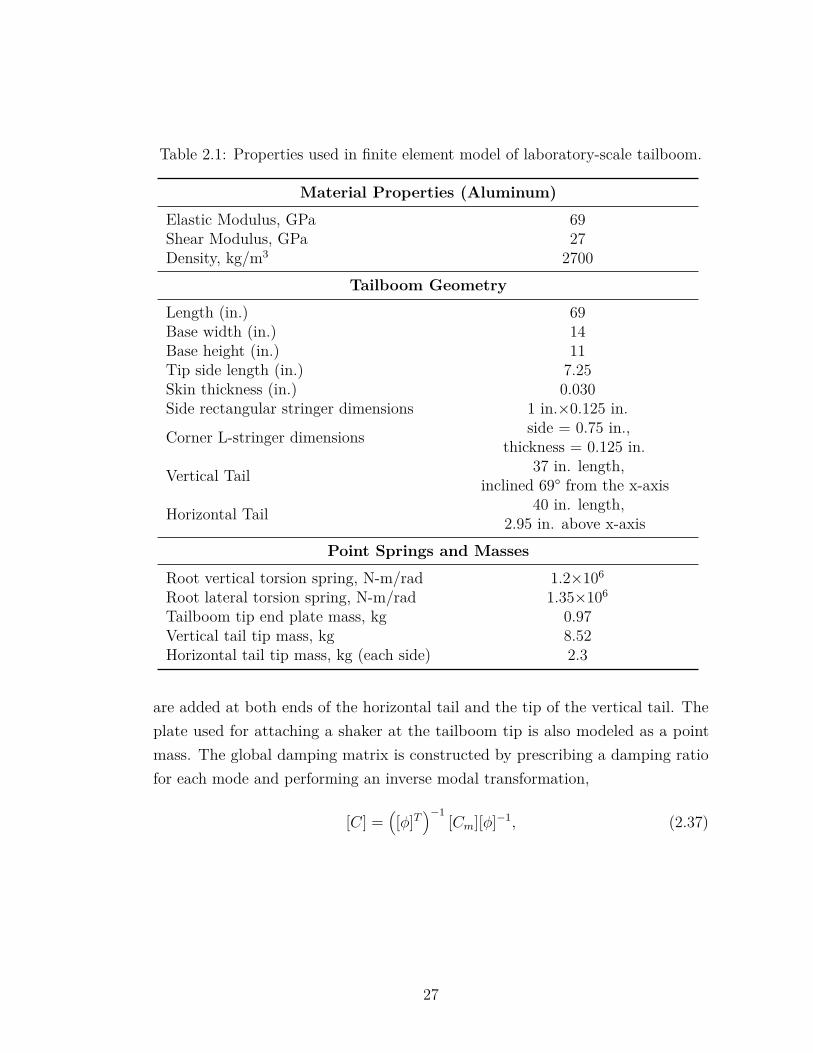
Table 2.1: Properties used in finite element model of laboratory-scale tailboom.
Material Properties (Aluminum)
Elastic Modulus, GPa 69Shear Modulus, GPa 27Density, kg/m3 2700
Tailboom Geometry
Length (in.) 69Base width (in.) 14Base height (in.) 11Tip side length (in.) 7.25Skin thickness (in.) 0.030Side rectangular stringer dimensions 1 in.×0.125 in.
Corner L-stringer dimensions side = 0.75 in.,thickness = 0.125 in.
Vertical Tail 37 in. length,inclined 69° from the x-axis
Horizontal Tail 40 in. length,2.95 in. above x-axis
Point Springs and Masses
Root vertical torsion spring, N-m/rad 1.2×10⁶
Root lateral torsion spring, N-m/rad 1.35×10⁶
Tailboom tip end plate mass, kg 0.97Vertical tail tip mass, kg 8.52Horizontal tail tip mass, kg (each side) 2.3
are added at both ends of the horizontal tail and the tip of the vertical tail. Theplate used for attaching a shaker at the tailboom tip is also modeled as a pointmass. The global damping matrix is constructed by prescribing a damping ratiofor each mode and performing an inverse modal transformation,
[C] =([φ]T
)−1[Cm][φ]−1, (2.37)
27
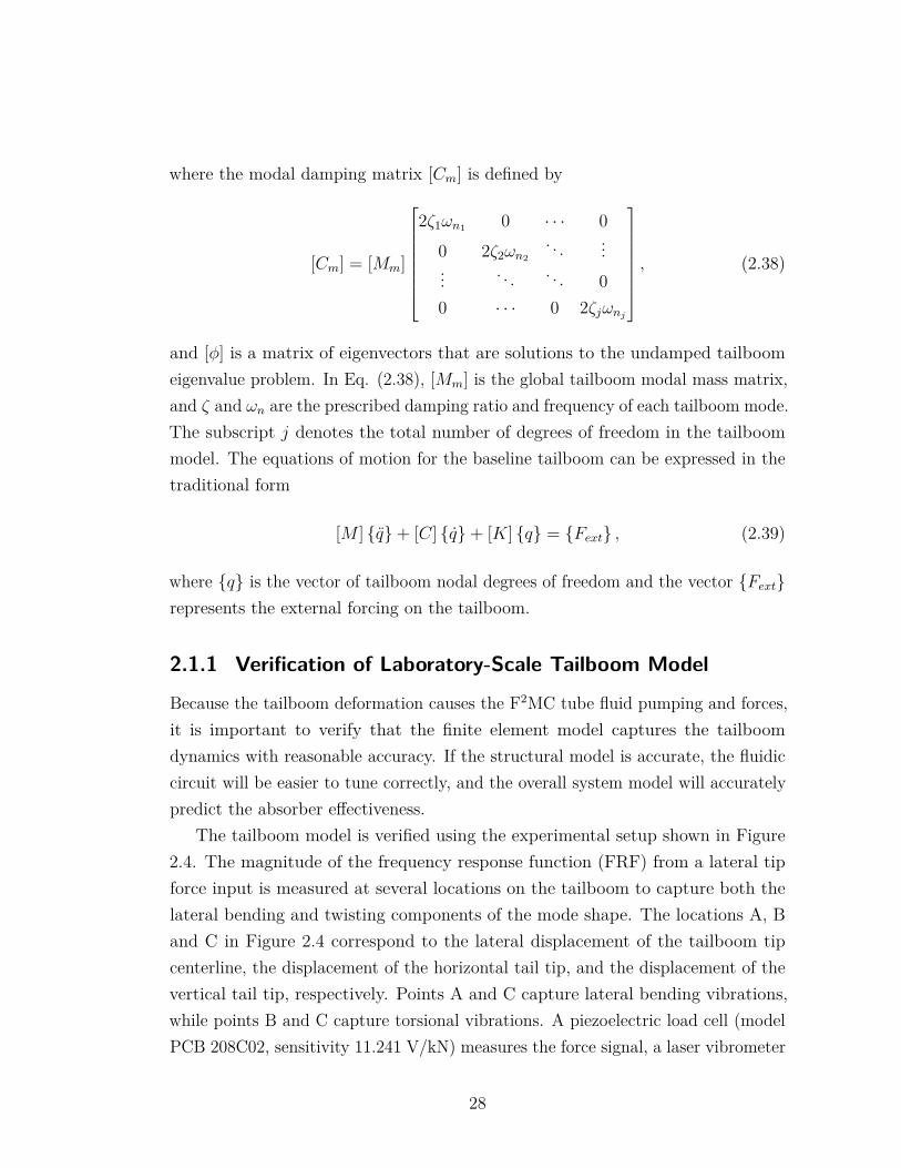
where the modal damping matrix [Cm] is defined by
[Cm] = [Mm]
2ζ1ωn1 0 · · · 00 2ζ2ωn2
. . . ...... . . . . . . 00 · · · 0 2ζjωnj
, (2.38)
and [φ] is a matrix of eigenvectors that are solutions to the undamped tailboomeigenvalue problem. In Eq. (2.38), [Mm] is the global tailboom modal mass matrix,and ζ and ωn are the prescribed damping ratio and frequency of each tailboom mode.The subscript j denotes the total number of degrees of freedom in the tailboommodel. The equations of motion for the baseline tailboom can be expressed in thetraditional form
[M ] q+ [C] q+ [K] q = Fext , (2.39)
where q is the vector of tailboom nodal degrees of freedom and the vector Fextrepresents the external forcing on the tailboom.
2.1.1 Verification of Laboratory-Scale Tailboom Model
Because the tailboom deformation causes the F2MC tube fluid pumping and forces,it is important to verify that the finite element model captures the tailboomdynamics with reasonable accuracy. If the structural model is accurate, the fluidiccircuit will be easier to tune correctly, and the overall system model will accuratelypredict the absorber effectiveness.
The tailboom model is verified using the experimental setup shown in Figure2.4. The magnitude of the frequency response function (FRF) from a lateral tipforce input is measured at several locations on the tailboom to capture both thelateral bending and twisting components of the mode shape. The locations A, Band C in Figure 2.4 correspond to the lateral displacement of the tailboom tipcenterline, the displacement of the horizontal tail tip, and the displacement of thevertical tail tip, respectively. Points A and C capture lateral bending vibrations,while points B and C capture torsional vibrations. A piezoelectric load cell (modelPCB 208C02, sensitivity 11.241 V/kN) measures the force signal, a laser vibrometer
28
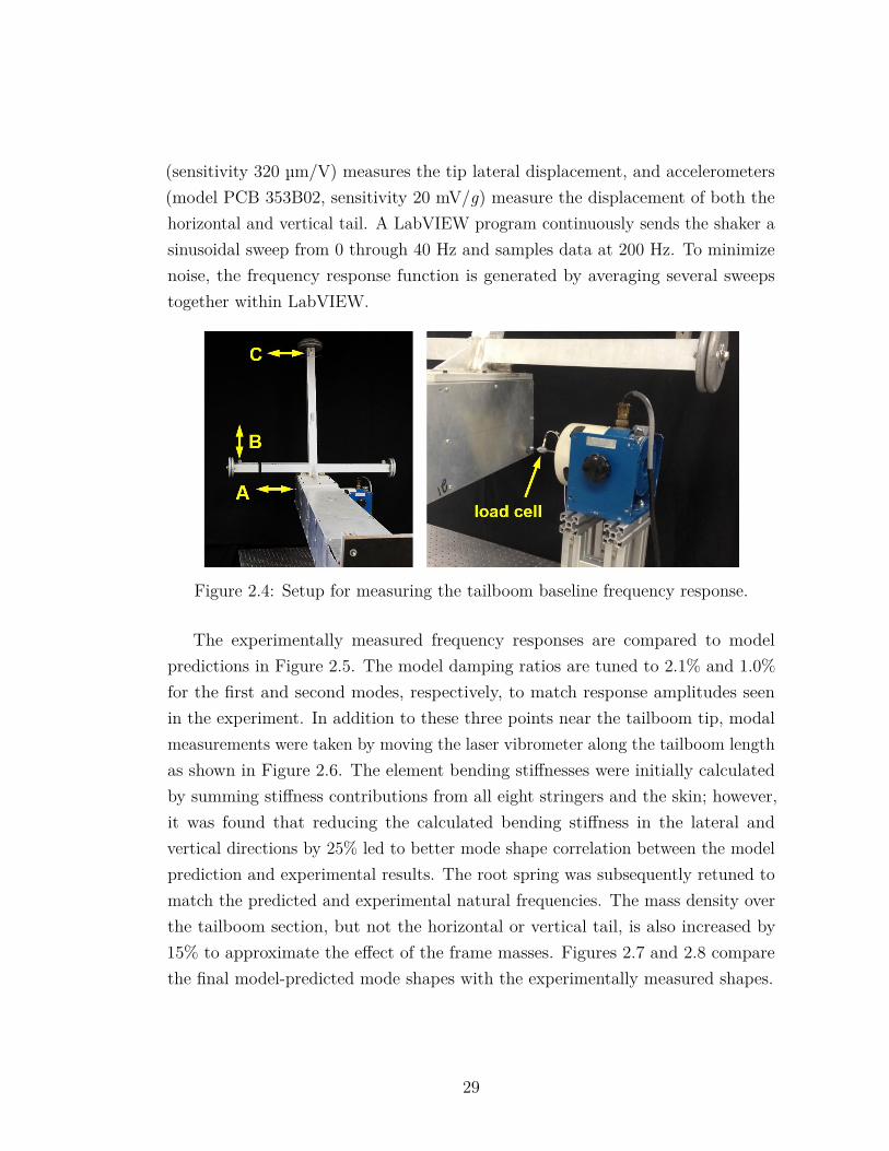
(sensitivity 320 µm/V) measures the tip lateral displacement, and accelerometers(model PCB 353B02, sensitivity 20 mV/g) measure the displacement of both thehorizontal and vertical tail. A LabVIEW program continuously sends the shaker asinusoidal sweep from 0 through 40 Hz and samples data at 200 Hz. To minimizenoise, the frequency response function is generated by averaging several sweepstogether within LabVIEW.
Figure 2.4: Setup for measuring the tailboom baseline frequency response.
The experimentally measured frequency responses are compared to modelpredictions in Figure 2.5. The model damping ratios are tuned to 2.1% and 1.0%for the first and second modes, respectively, to match response amplitudes seenin the experiment. In addition to these three points near the tailboom tip, modalmeasurements were taken by moving the laser vibrometer along the tailboom lengthas shown in Figure 2.6. The element bending stiffnesses were initially calculatedby summing stiffness contributions from all eight stringers and the skin; however,it was found that reducing the calculated bending stiffness in the lateral andvertical directions by 25% led to better mode shape correlation between the modelprediction and experimental results. The root spring was subsequently retuned tomatch the predicted and experimental natural frequencies. The mass density overthe tailboom section, but not the horizontal or vertical tail, is also increased by15% to approximate the effect of the frame masses. Figures 2.7 and 2.8 comparethe final model-predicted mode shapes with the experimentally measured shapes.
29
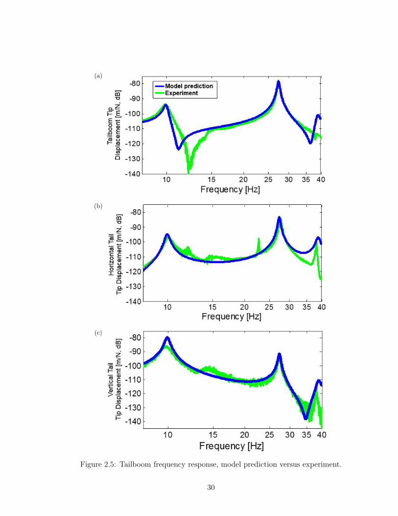
(a)
(b)
(c)
Figure 2.5: Tailboom frequency response, model prediction versus experiment.
30
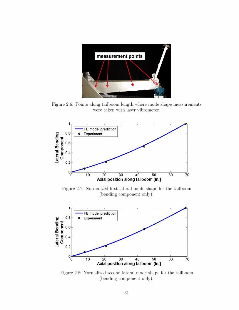
Figure 2.6: Points along tailboom length where mode shape measurementswere taken with laser vibrometer.
Figure 2.7: Normalized first lateral mode shape for the tailboom(bending component only).
Figure 2.8: Normalized second lateral mode shape for the tailboom(bending component only).
31
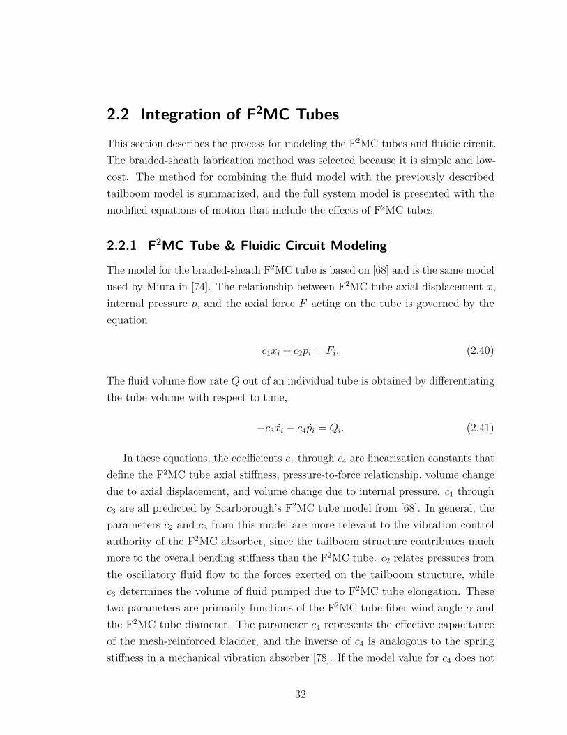
2.2 Integration of F2MC TubesThis section describes the process for modeling the F2MC tubes and fluidic circuit.The braided-sheath fabrication method was selected because it is simple and low-cost. The method for combining the fluid model with the previously describedtailboom model is summarized, and the full system model is presented with themodified equations of motion that include the effects of F2MC tubes.
2.2.1 F2MC Tube & Fluidic Circuit Modeling
The model for the braided-sheath F2MC tube is based on [68] and is the same modelused by Miura in [74]. The relationship between F2MC tube axial displacement x,internal pressure p, and the axial force F acting on the tube is governed by theequation
c1xi + c2pi = Fi. (2.40)
The fluid volume flow rate Q out of an individual tube is obtained by differentiatingthe tube volume with respect to time,
−c3xi − c4pi = Qi. (2.41)
In these equations, the coefficients c1 through c4 are linearization constants thatdefine the F2MC tube axial stiffness, pressure-to-force relationship, volume changedue to axial displacement, and volume change due to internal pressure. c1 throughc3 are all predicted by Scarborough’s F2MC tube model from [68]. In general, theparameters c2 and c3 from this model are more relevant to the vibration controlauthority of the F2MC absorber, since the tailboom structure contributes muchmore to the overall bending stiffness than the F2MC tube. c2 relates pressures fromthe oscillatory fluid flow to the forces exerted on the tailboom structure, whilec3 determines the volume of fluid pumped due to F2MC tube elongation. Thesetwo parameters are primarily functions of the F2MC tube fiber wind angle α andthe F2MC tube diameter. The parameter c4 represents the effective capacitanceof the mesh-reinforced bladder, and the inverse of c4 is analogous to the springstiffness in a mechanical vibration absorber [78]. If the model value for c4 does not
32
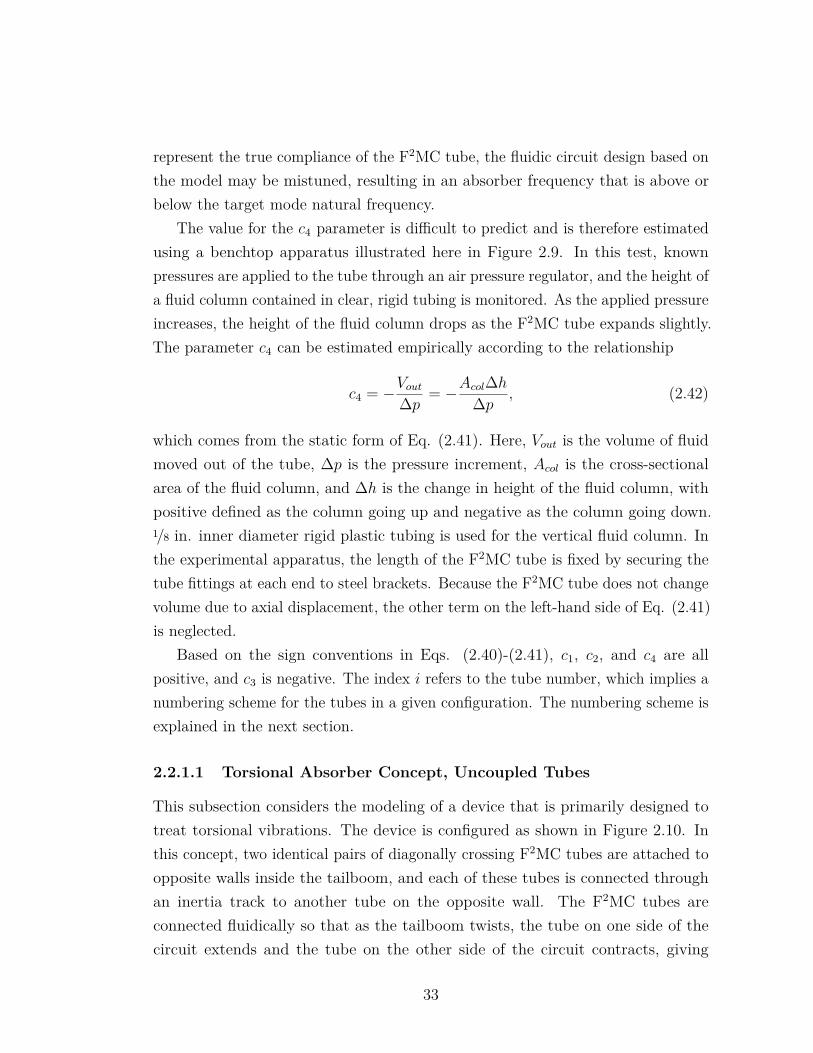
represent the true compliance of the F2MC tube, the fluidic circuit design based onthe model may be mistuned, resulting in an absorber frequency that is above orbelow the target mode natural frequency.
The value for the c4 parameter is difficult to predict and is therefore estimatedusing a benchtop apparatus illustrated here in Figure 2.9. In this test, knownpressures are applied to the tube through an air pressure regulator, and the height ofa fluid column contained in clear, rigid tubing is monitored. As the applied pressureincreases, the height of the fluid column drops as the F2MC tube expands slightly.The parameter c4 can be estimated empirically according to the relationship
c4 = −Vout∆p = −Acol∆h∆p , (2.42)
which comes from the static form of Eq. (2.41). Here, Vout is the volume of fluidmoved out of the tube, ∆p is the pressure increment, Acol is the cross-sectionalarea of the fluid column, and ∆h is the change in height of the fluid column, withpositive defined as the column going up and negative as the column going down.1/8 in. inner diameter rigid plastic tubing is used for the vertical fluid column. Inthe experimental apparatus, the length of the F2MC tube is fixed by securing thetube fittings at each end to steel brackets. Because the F2MC tube does not changevolume due to axial displacement, the other term on the left-hand side of Eq. (2.41)is neglected.
Based on the sign conventions in Eqs. (2.40)-(2.41), c1, c2, and c4 are allpositive, and c3 is negative. The index i refers to the tube number, which implies anumbering scheme for the tubes in a given configuration. The numbering scheme isexplained in the next section.
2.2.1.1 Torsional Absorber Concept, Uncoupled Tubes
This subsection considers the modeling of a device that is primarily designed totreat torsional vibrations. The device is configured as shown in Figure 2.10. Inthis concept, two identical pairs of diagonally crossing F2MC tubes are attached toopposite walls inside the tailboom, and each of these tubes is connected throughan inertia track to another tube on the opposite wall. The F2MC tubes areconnected fluidically so that as the tailboom twists, the tube on one side of thecircuit extends and the tube on the other side of the circuit contracts, giving
33
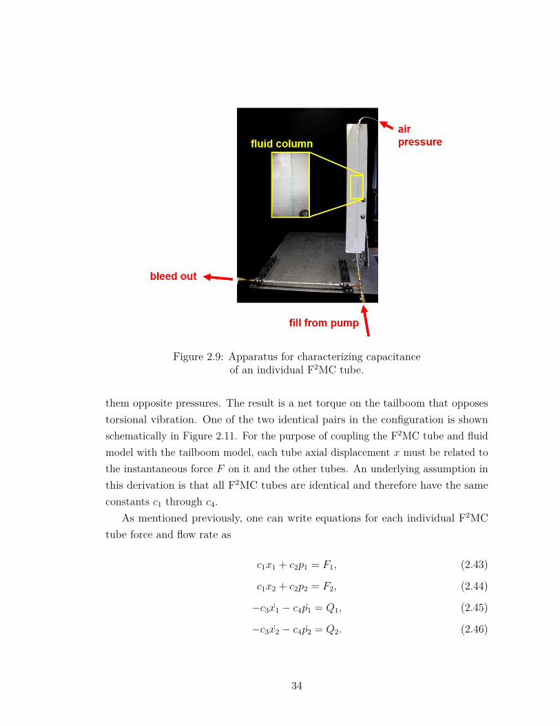
Figure 2.9: Apparatus for characterizing capacitanceof an individual F2MC tube.
them opposite pressures. The result is a net torque on the tailboom that opposestorsional vibration. One of the two identical pairs in the configuration is shownschematically in Figure 2.11. For the purpose of coupling the F2MC tube and fluidmodel with the tailboom model, each tube axial displacement x must be related tothe instantaneous force F on it and the other tubes. An underlying assumption inthis derivation is that all F2MC tubes are identical and therefore have the sameconstants c1 through c4.
As mentioned previously, one can write equations for each individual F2MCtube force and flow rate as
c1x1 + c2p1 = F1, (2.43)
c1x2 + c2p2 = F2, (2.44)
−c3x1 − c4p1 = Q1, (2.45)
−c3x2 − c4p2 = Q2. (2.46)
34
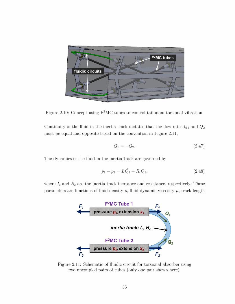
Figure 2.10: Concept using F2MC tubes to control tailboom torsional vibration.
Continuity of the fluid in the inertia track dictates that the flow rates Q1 and Q2
must be equal and opposite based on the convention in Figure 2.11,
Q1 = −Q2. (2.47)
The dynamics of the fluid in the inertia track are governed by
p1 − p2 = IcQ1 +RcQ1, (2.48)
where Ic and Rc are the inertia track inertance and resistance, respectively. Theseparameters are functions of fluid density ρ, fluid dynamic viscosity µ, track length
Figure 2.11: Schematic of fluidic circuit for torsional absorber usingtwo uncoupled pairs of tubes (only one pair shown here).
35
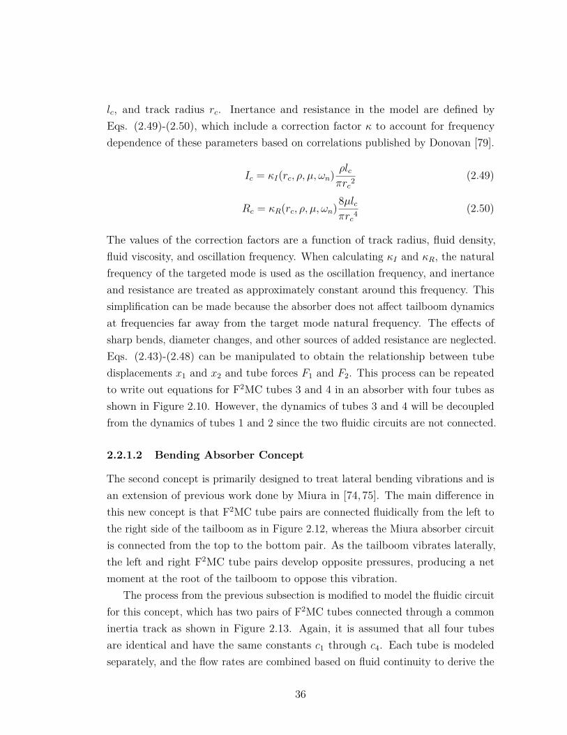
lc, and track radius rc. Inertance and resistance in the model are defined byEqs. (2.49)-(2.50), which include a correction factor κ to account for frequencydependence of these parameters based on correlations published by Donovan [79].
Ic = κI(rc, ρ, µ, ωn) ρlcπrc2
(2.49)
Rc = κR(rc, ρ, µ, ωn)8µlcπrc4
(2.50)
The values of the correction factors are a function of track radius, fluid density,fluid viscosity, and oscillation frequency. When calculating κI and κR, the naturalfrequency of the targeted mode is used as the oscillation frequency, and inertanceand resistance are treated as approximately constant around this frequency. Thissimplification can be made because the absorber does not affect tailboom dynamicsat frequencies far away from the target mode natural frequency. The effects ofsharp bends, diameter changes, and other sources of added resistance are neglected.Eqs. (2.43)-(2.48) can be manipulated to obtain the relationship between tubedisplacements x1 and x2 and tube forces F1 and F2. This process can be repeatedto write out equations for F2MC tubes 3 and 4 in an absorber with four tubes asshown in Figure 2.10. However, the dynamics of tubes 3 and 4 will be decoupledfrom the dynamics of tubes 1 and 2 since the two fluidic circuits are not connected.
2.2.1.2 Bending Absorber Concept
The second concept is primarily designed to treat lateral bending vibrations and isan extension of previous work done by Miura in [74, 75]. The main difference inthis new concept is that F2MC tube pairs are connected fluidically from the left tothe right side of the tailboom as in Figure 2.12, whereas the Miura absorber circuitis connected from the top to the bottom pair. As the tailboom vibrates laterally,the left and right F2MC tube pairs develop opposite pressures, producing a netmoment at the root of the tailboom to oppose this vibration.
The process from the previous subsection is modified to model the fluidic circuitfor this concept, which has two pairs of F2MC tubes connected through a commoninertia track as shown in Figure 2.13. Again, it is assumed that all four tubesare identical and have the same constants c1 through c4. Each tube is modeledseparately, and the flow rates are combined based on fluid continuity to derive the
36
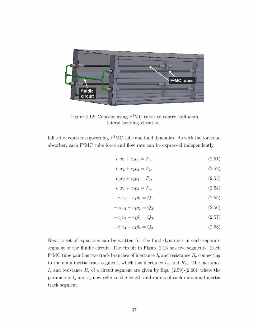
Figure 2.12: Concept using F2MC tubes to control tailboomlateral bending vibration.
full set of equations governing F2MC tube and fluid dynamics. As with the torsionalabsorber, each F2MC tube force and flow rate can be expressed independently,
c1x1 + c2p1 = F1, (2.51)
c1x2 + c2p2 = F2, (2.52)
c1x3 + c2p3 = F3, (2.53)
c1x4 + c2p4 = F4, (2.54)
−c3x1 − c4p1 = Q1, (2.55)
−c3x2 − c4p2 = Q2, (2.56)
−c3x3 − c4p3 = Q3, (2.57)
−c3x4 − c4p4 = Q4. (2.58)
Next, a set of equations can be written for the fluid dynamics in each separatesegment of the fluidic circuit. The circuit in Figure 2.13 has five segments. EachF2MC tube pair has two track branches of inertance Ib and resistance Rb connectingto the main inertia track segment, which has inertance Im and Rm. The inertanceIs and resistance Rs of a circuit segment are given by Eqs. (2.59)-(2.60), where theparameters ls and rs now refer to the length and radius of each individual inertiatrack segment.
37
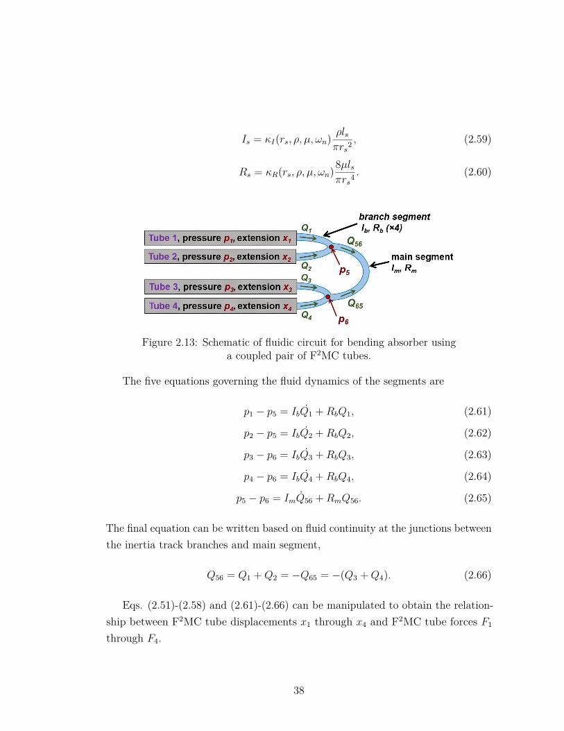
Is = κI(rs, ρ, µ, ωn) ρlsπrs2 , (2.59)
Rs = κR(rs, ρ, µ, ωn)8µlsπrs4 . (2.60)
Figure 2.13: Schematic of fluidic circuit for bending absorber usinga coupled pair of F2MC tubes.
The five equations governing the fluid dynamics of the segments are
p1 − p5 = IbQ1 +RbQ1, (2.61)
p2 − p5 = IbQ2 +RbQ2, (2.62)
p3 − p6 = IbQ3 +RbQ3, (2.63)
p4 − p6 = IbQ4 +RbQ4, (2.64)
p5 − p6 = ImQ56 +RmQ56. (2.65)
The final equation can be written based on fluid continuity at the junctions betweenthe inertia track branches and main segment,
Q56 = Q1 +Q2 = −Q65 = −(Q3 +Q4). (2.66)
Eqs. (2.51)-(2.58) and (2.61)-(2.66) can be manipulated to obtain the relation-ship between F2MC tube displacements x1 through x4 and F2MC tube forces F1
through F4.
38
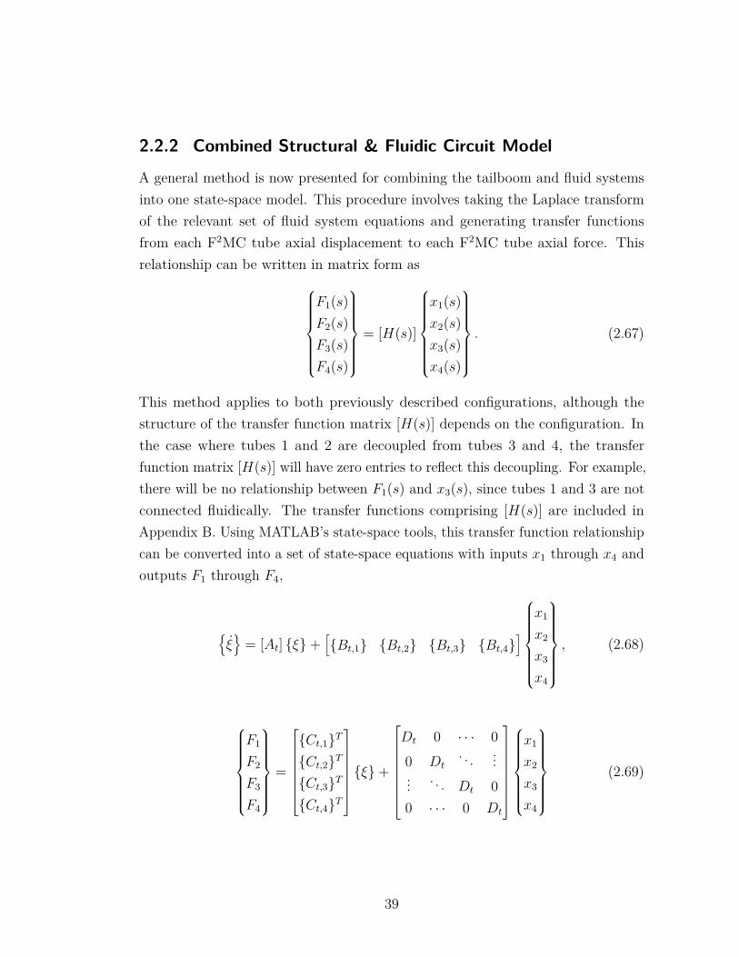
2.2.2 Combined Structural & Fluidic Circuit Model
A general method is now presented for combining the tailboom and fluid systemsinto one state-space model. This procedure involves taking the Laplace transformof the relevant set of fluid system equations and generating transfer functionsfrom each F2MC tube axial displacement to each F2MC tube axial force. Thisrelationship can be written in matrix form as
F1(s)F2(s)F3(s)F4(s)
= [H(s)]
x1(s)x2(s)x3(s)x4(s)
. (2.67)
This method applies to both previously described configurations, although thestructure of the transfer function matrix [H(s)] depends on the configuration. Inthe case where tubes 1 and 2 are decoupled from tubes 3 and 4, the transferfunction matrix [H(s)] will have zero entries to reflect this decoupling. For example,there will be no relationship between F1(s) and x3(s), since tubes 1 and 3 are notconnected fluidically. The transfer functions comprising [H(s)] are included inAppendix B. Using MATLAB’s state-space tools, this transfer function relationshipcan be converted into a set of state-space equations with inputs x1 through x4 andoutputs F1 through F4,
ξ
= [At] ξ+[Bt,1 Bt,2 Bt,3 Bt,4
]
x1
x2
x3
x4
, (2.68)
F1
F2
F3
F4
=
Ct,1T
Ct,2T
Ct,3T
Ct,4T
ξ+
Dt 0 · · · 00 Dt
. . . ...... . . . Dt 00 · · · 0 Dt
x1
x2
x3
x4
(2.69)
39
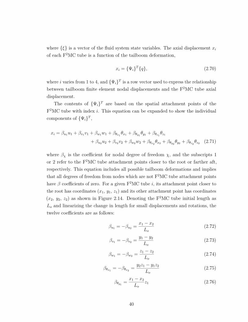
where ξ is a vector of the fluid system state variables. The axial displacement xiof each F2MC tube is a function of the tailboom deformation,
xi = ΨiTq, (2.70)
where i varies from 1 to 4, and ΨiT is a row vector used to express the relationshipbetween tailboom finite element nodal displacements and the F2MC tube axialdisplacement.
The contents of ΨiT are based on the spatial attachment points of theF2MC tube with index i. This equation can be expanded to show the individualcomponents of ΨiT ,
xi = βu1u1 + βv1v1 + βw1w1 + βθx1θx1 + βθy1
θy1 + βθz1θz1
+ βu2u2 + βv2v2 + βw2w2 + βθx2θx2 + βθy2
θy2 + βθz2θz2 (2.71)
where βχ is the coefficient for nodal degree of freedom χ, and the subscripts 1or 2 refer to the F2MC tube attachment points closer to the root or farther aft,respectively. This equation includes all possible tailboom deformations and impliesthat all degrees of freedom from nodes which are not F2MC tube attachment pointshave β coefficients of zero. For a given F2MC tube i, its attachment point closer tothe root has coordinates (x1, y1, z1) and its other attachment point has coordinates(x2, y2, z2) as shown in Figure 2.14. Denoting the F2MC tube initial length asLo and linearizing the change in length for small displacements and rotations, thetwelve coefficients are as follows:
βu1 = −βu2 = x1 − x2
Lo(2.72)
βv1 = −βv2 = y1 − y2
Lo(2.73)
βw1 = −βw2 = z1 − z2
Lo(2.74)
βθx1= −βθx2
= y2z1 − y1z2
Lo(2.75)
βθy1= x1 − x2
Loz1 (2.76)
40
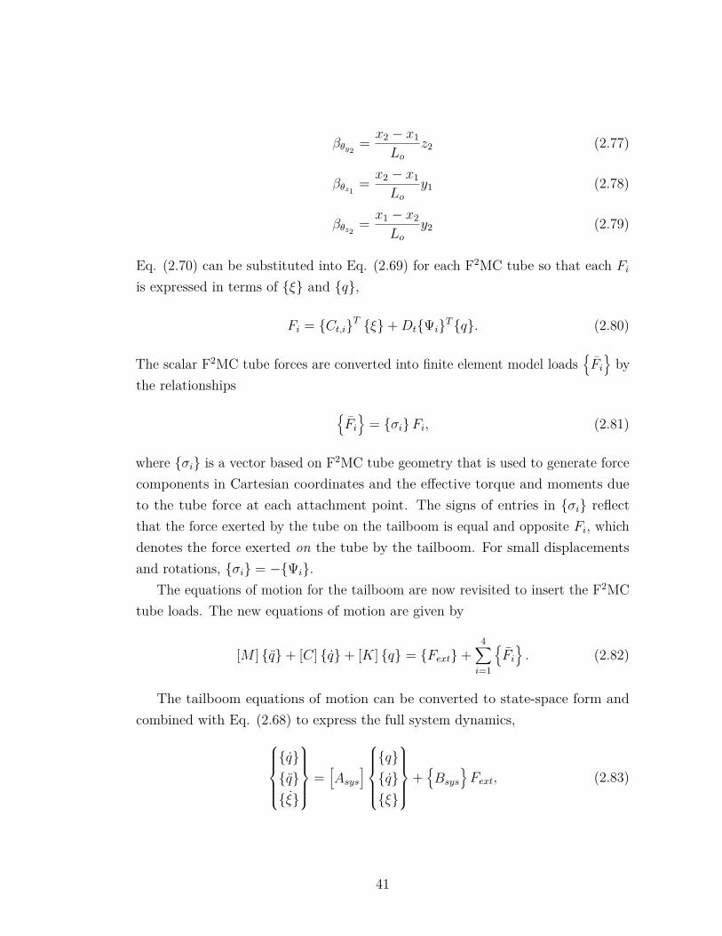
βθy2= x2 − x1
Loz2 (2.77)
βθz1= x2 − x1
Loy1 (2.78)
βθz2= x1 − x2
Loy2 (2.79)
Eq. (2.70) can be substituted into Eq. (2.69) for each F2MC tube so that each Fiis expressed in terms of ξ and q,
Fi = Ct,iT ξ+DtΨiTq. (2.80)
The scalar F2MC tube forces are converted into finite element model loadsFiby
the relationships
Fi
= σiFi, (2.81)
where σi is a vector based on F2MC tube geometry that is used to generate forcecomponents in Cartesian coordinates and the effective torque and moments dueto the tube force at each attachment point. The signs of entries in σi reflectthat the force exerted by the tube on the tailboom is equal and opposite Fi, whichdenotes the force exerted on the tube by the tailboom. For small displacementsand rotations, σi = −Ψi.
The equations of motion for the tailboom are now revisited to insert the F2MCtube loads. The new equations of motion are given by
[M ] q+ [C] q+ [K] q = Fext+4∑i=1
Fi. (2.82)
The tailboom equations of motion can be converted to state-space form andcombined with Eq. (2.68) to express the full system dynamics,
qqξ
=[Asys
]qqξ
+Bsys
Fext, (2.83)
41
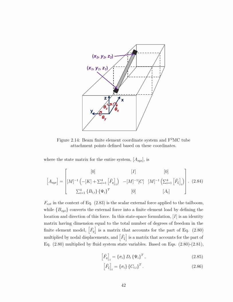
Figure 2.14: Beam finite element coordinate system and F2MC tubeattachment points defined based on these coordinates.
where the state matrix for the entire system, [Asys], is
[Asys
]=
[0] [I] [0]
[M ]−1(−[K] +∑4
i=1
[Fq]i
)−[M ]−1[C] [M ]−1
(∑4i=1
[Fξ]i
)∑4i=1 Bt,i ΨiT [0] [At]
. (2.84)
Fext in the context of Eq. (2.83) is the scalar external force applied to the tailboom,while Bsys converts the external force into a finite element load by defining thelocation and direction of this force. In this state-space formulation, [I] is an identitymatrix having dimension equal to the total number of degrees of freedom in thefinite element model,
[Fq]is a matrix that accounts for the part of Eq. (2.80)
multiplied by nodal displacements, and[Fξ]is a matrix that accounts for the part of
Eq. (2.80) multiplied by fluid system state variables. Based on Eqs. (2.80)-(2.81),
[Fq]i
= σiDt ΨiT , (2.85)[Fξ]i
= σi Ct,iT . (2.86)
42
Because they are part of the overall system state vector, tailboom nodal degrees offreedom can easily be chosen as outputs for the state-space model.
2.3 Simulation Results & Parametric StudiesIn this section, some simulation results are presented to show general trendsand attempt to understand how the proposed F2MC absorbers can be effectivelydesigned. Comparisons between the two previously described configurations aremade, and a parametric study is conducted to examine the effect of changingdifferent F2MC tube or fluidic circuit properties.
2.3.1 Torsional Absorber Versus Bending Absorber Comparison
One of the main early goals of this research was to determine the most effectiveF2MC tube and circuit configuration for reducing vibrations in bending/torsioncoupled modes. The F2MC-integrated tailboom model is used to compare theeffectiveness of the two proposed absorbers for reducing vibration of the secondlateral bending/torsion mode, which has a natural frequency between 26 and 27Hz. The natural frequencies of the tailboom test stand were found to changeslightly with forcing amplitude; therefore, a level of forcing was selected that couldeffectively excite the tailboom bending modes and allow for demonstration of theF2MC vibration absorber. The natural frequency measured in experiments at thechosen forcing level was 26.7 Hz.
The 26.7 Hz lateral bending/torsion mode is chosen as the target mode fordemonstrating an F2MC absorber because the 10 Hz and 38 Hz modes are dominatedby tail deformation. An absorber with F2MC tubes attached to the root of thetailboom would be ineffective at reducing vibrations of these tail modes since mostof the modal deformation occurs away from the root. The first two model-predictedlateral bending/torsion mode shapes are plotted in Figure 2.15 to illustrate thedifference between a local tail mode and a global tailboom mode. The second modenatural frequency is significantly higher than the 12.2 Hz target mode for Miura’stailboom absorber [74]. In Figure 2.16, the n/rev frequencies of existing three-bladed and four-bladed helicopters are plotted, and 26.7 Hz is near or above most ofthese helicopters’ n/rev frequencies. Therefore, demonstrating vibration reduction
43
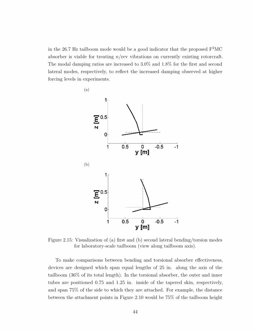
in the 26.7 Hz tailboom mode would be a good indicator that the proposed F2MCabsorber is viable for treating n/rev vibrations on currently existing rotorcraft.The modal damping ratios are increased to 3.0% and 1.8% for the first and secondlateral modes, respectively, to reflect the increased damping observed at higherforcing levels in experiments.
(a)
(b)
Figure 2.15: Visualization of (a) first and (b) second lateral bending/torsion modesfor laboratory-scale tailboom (view along tailboom axis).
To make comparisons between bending and torsional absorber effectiveness,devices are designed which span equal lengths of 25 in. along the axis of thetailboom (36% of its total length). In the torsional absorber, the outer and innertubes are positioned 0.75 and 1.25 in. inside of the tapered skin, respectively,and span 75% of the side to which they are attached. For example, the distancebetween the attachment points in Figure 2.10 would be 75% of the tailboom height
44
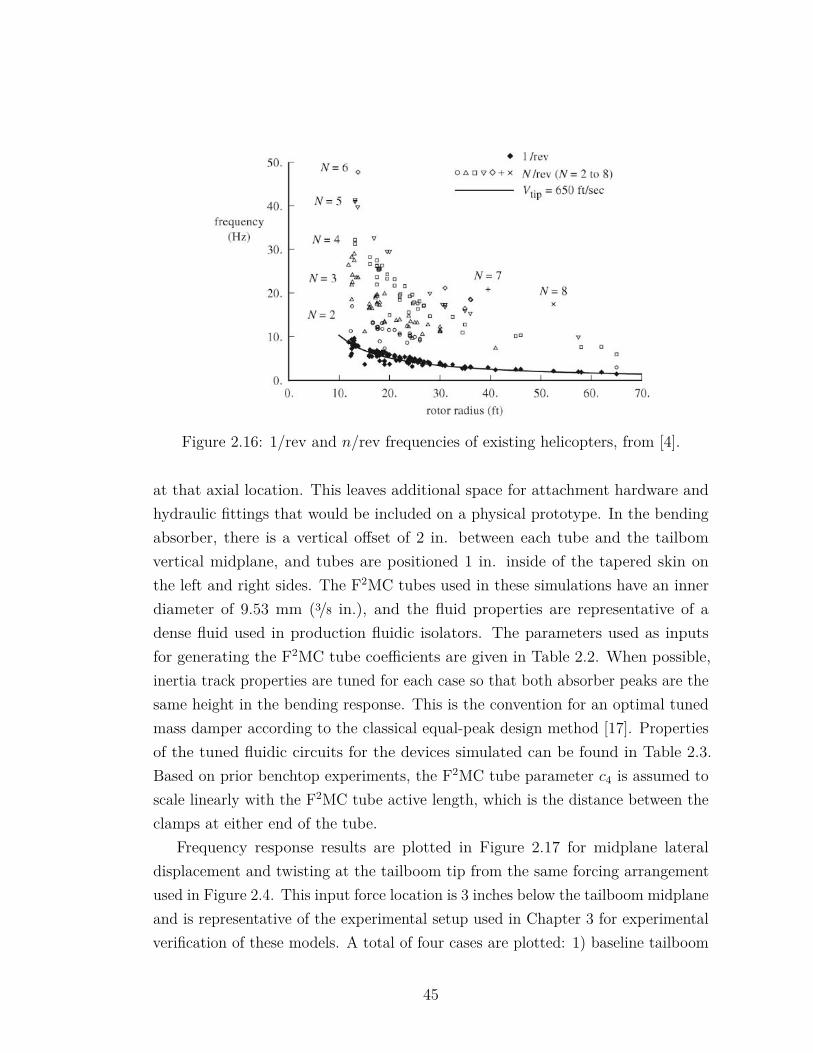
Figure 2.16: 1/rev and n/rev frequencies of existing helicopters, from [4].
at that axial location. This leaves additional space for attachment hardware andhydraulic fittings that would be included on a physical prototype. In the bendingabsorber, there is a vertical offset of 2 in. between each tube and the tailbomvertical midplane, and tubes are positioned 1 in. inside of the tapered skin onthe left and right sides. The F2MC tubes used in these simulations have an innerdiameter of 9.53 mm (3/8 in.), and the fluid properties are representative of adense fluid used in production fluidic isolators. The parameters used as inputsfor generating the F2MC tube coefficients are given in Table 2.2. When possible,inertia track properties are tuned for each case so that both absorber peaks are thesame height in the bending response. This is the convention for an optimal tunedmass damper according to the classical equal-peak design method [17]. Propertiesof the tuned fluidic circuits for the devices simulated can be found in Table 2.3.Based on prior benchtop experiments, the F2MC tube parameter c4 is assumed toscale linearly with the F2MC tube active length, which is the distance between theclamps at either end of the tube.
Frequency response results are plotted in Figure 2.17 for midplane lateraldisplacement and twisting at the tailboom tip from the same forcing arrangementused in Figure 2.4. This input force location is 3 inches below the tailboom midplaneand is representative of the experimental setup used in Chapter 3 for experimentalverification of these models. A total of four cases are plotted: 1) baseline tailboom
45
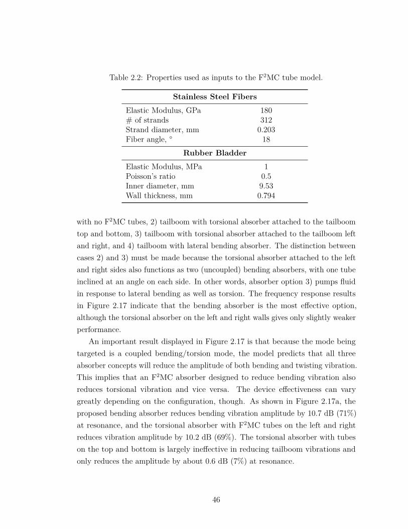
Table 2.2: Properties used as inputs to the F2MC tube model.
Stainless Steel Fibers
Elastic Modulus, GPa 180# of strands 312Strand diameter, mm 0.203Fiber angle, ° 18
Rubber Bladder
Elastic Modulus, MPa 1Poisson’s ratio 0.5Inner diameter, mm 9.53Wall thickness, mm 0.794
with no F2MC tubes, 2) tailboom with torsional absorber attached to the tailboomtop and bottom, 3) tailboom with torsional absorber attached to the tailboom leftand right, and 4) tailboom with lateral bending absorber. The distinction betweencases 2) and 3) must be made because the torsional absorber attached to the leftand right sides also functions as two (uncoupled) bending absorbers, with one tubeinclined at an angle on each side. In other words, absorber option 3) pumps fluidin response to lateral bending as well as torsion. The frequency response resultsin Figure 2.17 indicate that the bending absorber is the most effective option,although the torsional absorber on the left and right walls gives only slightly weakerperformance.
An important result displayed in Figure 2.17 is that because the mode beingtargeted is a coupled bending/torsion mode, the model predicts that all threeabsorber concepts will reduce the amplitude of both bending and twisting vibration.This implies that an F2MC absorber designed to reduce bending vibration alsoreduces torsional vibration and vice versa. The device effectiveness can varygreatly depending on the configuration, though. As shown in Figure 2.17a, theproposed bending absorber reduces bending vibration amplitude by 10.7 dB (71%)at resonance, and the torsional absorber with F2MC tubes on the left and rightreduces vibration amplitude by 10.2 dB (69%). The torsional absorber with tubeson the top and bottom is largely ineffective in reducing tailboom vibrations andonly reduces the amplitude by about 0.6 dB (7%) at resonance.
46
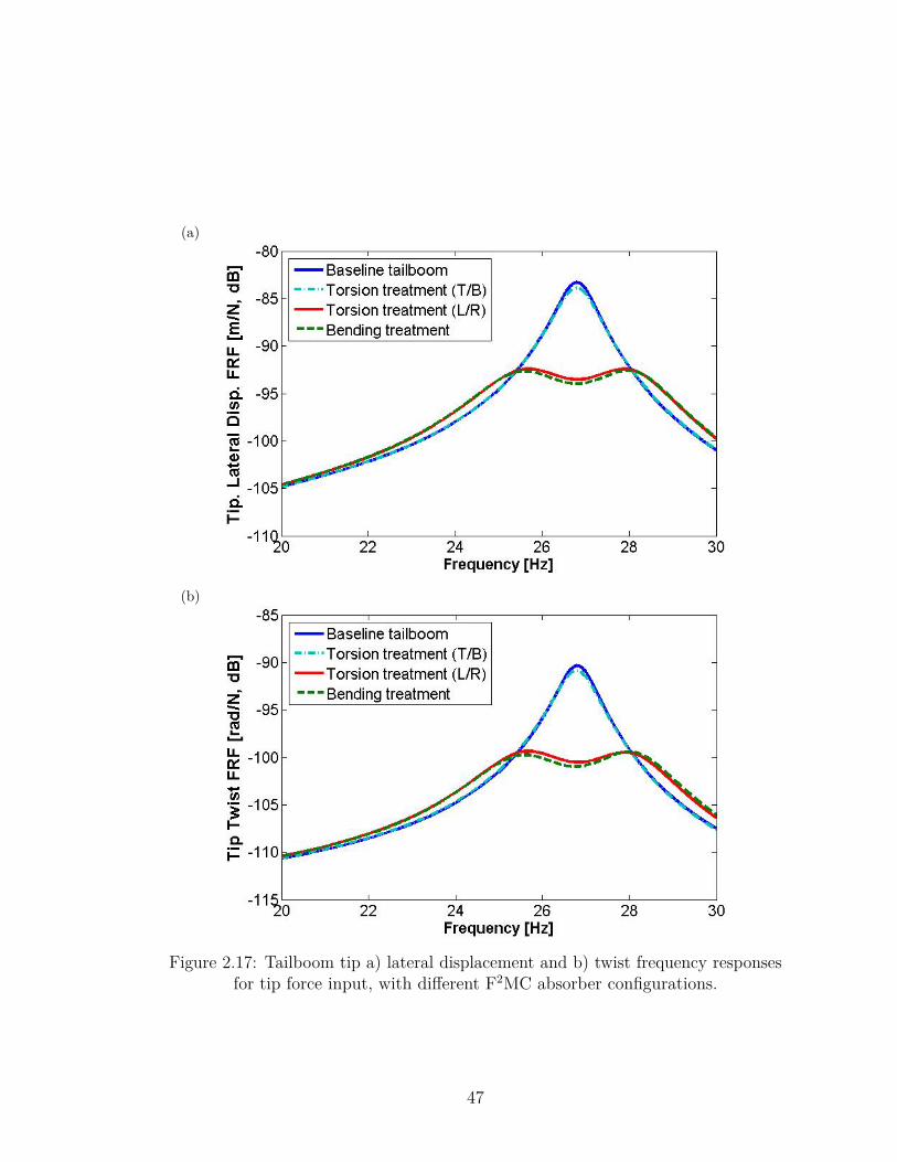
(a)
(b)
Figure 2.17: Tailboom tip a) lateral displacement and b) twist frequency responsesfor tip force input, with different F2MC absorber configurations.
47
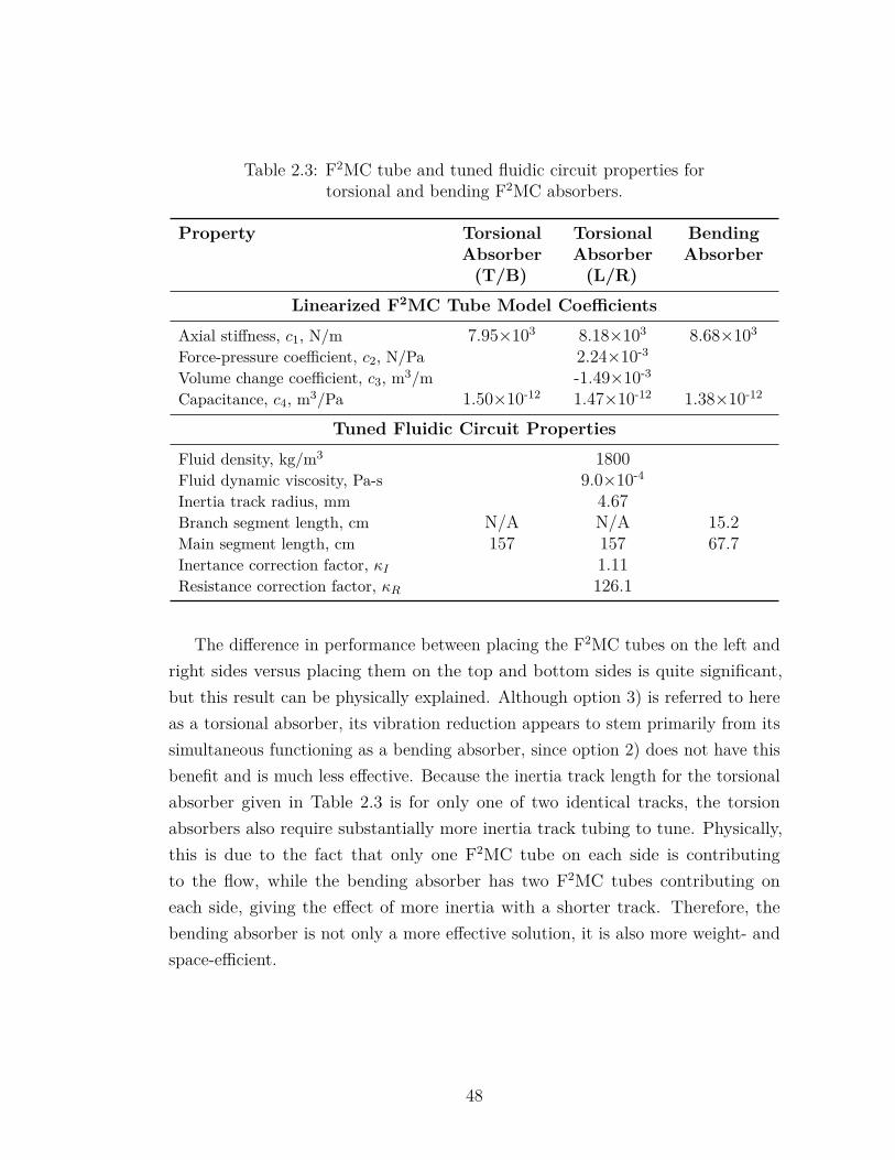
Table 2.3: F2MC tube and tuned fluidic circuit properties fortorsional and bending F2MC absorbers.
Property TorsionalAbsorber(T/B)
TorsionalAbsorber(L/R)
BendingAbsorber
Linearized F2MC Tube Model Coefficients
Axial stiffness, c1, N/m 7.95×10³ 8.18×10³ 8.68×10³
Force-pressure coefficient, c2, N/Pa 2.24×10⁻³
Volume change coefficient, c3, m3/m -1.49×10⁻³
Capacitance, c4, m3/Pa 1.50×10⁻¹² 1.47×10⁻¹² 1.38×10⁻¹²
Tuned Fluidic Circuit Properties
Fluid density, kg/m3 1800Fluid dynamic viscosity, Pa-s 9.0×10⁻⁴
Inertia track radius, mm 4.67Branch segment length, cm N/A N/A 15.2Main segment length, cm 157 157 67.7Inertance correction factor, κI 1.11Resistance correction factor, κR 126.1
The difference in performance between placing the F2MC tubes on the left andright sides versus placing them on the top and bottom sides is quite significant,but this result can be physically explained. Although option 3) is referred to hereas a torsional absorber, its vibration reduction appears to stem primarily from itssimultaneous functioning as a bending absorber, since option 2) does not have thisbenefit and is much less effective. Because the inertia track length for the torsionalabsorber given in Table 2.3 is for only one of two identical tracks, the torsionabsorbers also require substantially more inertia track tubing to tune. Physically,this is due to the fact that only one F2MC tube on each side is contributingto the flow, while the bending absorber has two F2MC tubes contributing oneach side, giving the effect of more inertia with a shorter track. Therefore, thebending absorber is not only a more effective solution, it is also more weight- andspace-efficient.
48
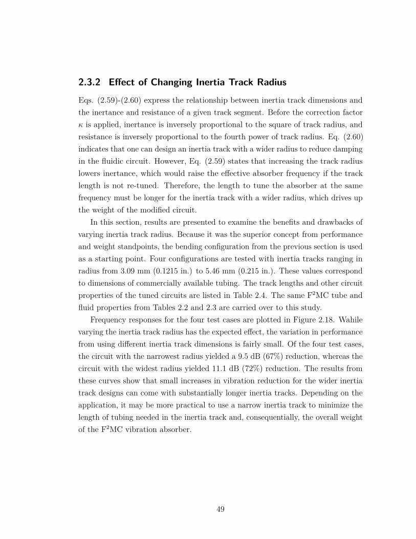
2.3.2 Effect of Changing Inertia Track Radius
Eqs. (2.59)-(2.60) express the relationship between inertia track dimensions andthe inertance and resistance of a given track segment. Before the correction factorκ is applied, inertance is inversely proportional to the square of track radius, andresistance is inversely proportional to the fourth power of track radius. Eq. (2.60)indicates that one can design an inertia track with a wider radius to reduce dampingin the fluidic circuit. However, Eq. (2.59) states that increasing the track radiuslowers inertance, which would raise the effective absorber frequency if the tracklength is not re-tuned. Therefore, the length to tune the absorber at the samefrequency must be longer for the inertia track with a wider radius, which drives upthe weight of the modified circuit.
In this section, results are presented to examine the benefits and drawbacks ofvarying inertia track radius. Because it was the superior concept from performanceand weight standpoints, the bending configuration from the previous section is usedas a starting point. Four configurations are tested with inertia tracks ranging inradius from 3.09 mm (0.1215 in.) to 5.46 mm (0.215 in.). These values correspondto dimensions of commercially available tubing. The track lengths and other circuitproperties of the tuned circuits are listed in Table 2.4. The same F2MC tube andfluid properties from Tables 2.2 and 2.3 are carried over to this study.
Frequency responses for the four test cases are plotted in Figure 2.18. Wahilevarying the inertia track radius has the expected effect, the variation in performancefrom using different inertia track dimensions is fairly small. Of the four test cases,the circuit with the narrowest radius yielded a 9.5 dB (67%) reduction, whereas thecircuit with the widest radius yielded 11.1 dB (72%) reduction. The results fromthese curves show that small increases in vibration reduction for the wider inertiatrack designs can come with substantially longer inertia tracks. Depending on theapplication, it may be more practical to use a narrow inertia track to minimize thelength of tubing needed in the inertia track and, consequentially, the overall weightof the F2MC vibration absorber.
49
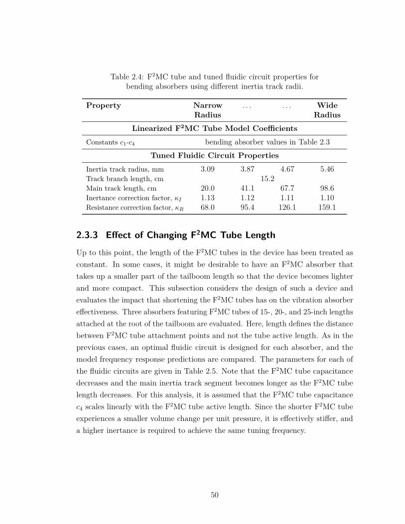
Table 2.4: F2MC tube and tuned fluidic circuit properties forbending absorbers using different inertia track radii.
Property NarrowRadius
. . . . . . WideRadius
Linearized F2MC Tube Model Coefficients
Constants c1-c4 bending absorber values in Table 2.3Tuned Fluidic Circuit Properties
Inertia track radius, mm 3.09 3.87 4.67 5.46Track branch length, cm 15.2Main track length, cm 20.0 41.1 67.7 98.6Inertance correction factor, κI 1.13 1.12 1.11 1.10Resistance correction factor, κR 68.0 95.4 126.1 159.1
2.3.3 Effect of Changing F2MC Tube Length
Up to this point, the length of the F2MC tubes in the device has been treated asconstant. In some cases, it might be desirable to have an F2MC absorber thattakes up a smaller part of the tailboom length so that the device becomes lighterand more compact. This subsection considers the design of such a device andevaluates the impact that shortening the F2MC tubes has on the vibration absorbereffectiveness. Three absorbers featuring F2MC tubes of 15-, 20-, and 25-inch lengthsattached at the root of the tailboom are evaluated. Here, length defines the distancebetween F2MC tube attachment points and not the tube active length. As in theprevious cases, an optimal fluidic circuit is designed for each absorber, and themodel frequency response predictions are compared. The parameters for each ofthe fluidic circuits are given in Table 2.5. Note that the F2MC tube capacitancedecreases and the main inertia track segment becomes longer as the F2MC tubelength decreases. For this analysis, it is assumed that the F2MC tube capacitancec4 scales linearly with the F2MC tube active length. Since the shorter F2MC tubeexperiences a smaller volume change per unit pressure, it is effectively stiffer, anda higher inertance is required to achieve the same tuning frequency.
50
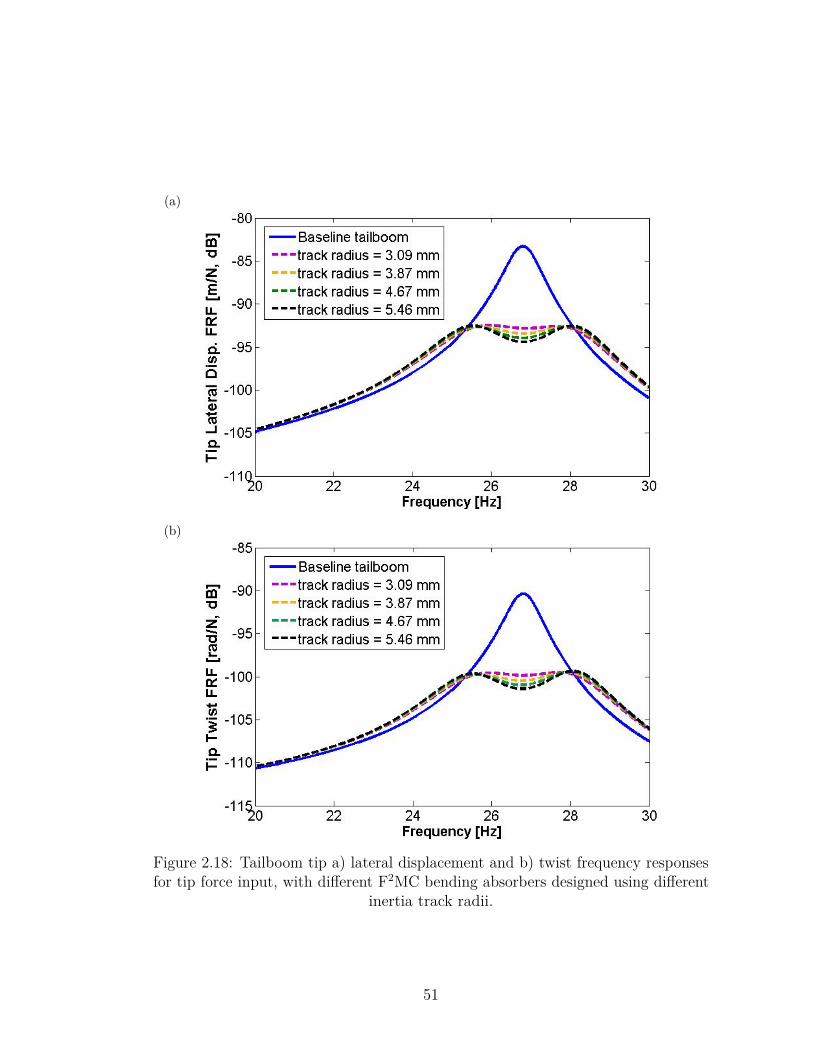
(a)
(b)
Figure 2.18: Tailboom tip a) lateral displacement and b) twist frequency responsesfor tip force input, with different F2MC bending absorbers designed using different
inertia track radii.
51
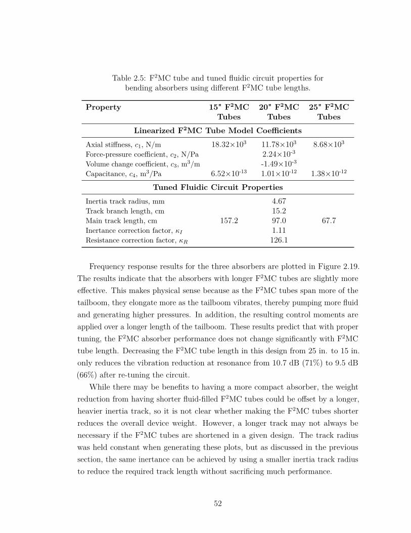
Table 2.5: F2MC tube and tuned fluidic circuit properties forbending absorbers using different F2MC tube lengths.
Property 15" F2MCTubes
20" F2MCTubes
25" F2MCTubes
Linearized F2MC Tube Model Coefficients
Axial stiffness, c1, N/m 18.32×10³ 11.78×10³ 8.68×10³
Force-pressure coefficient, c2, N/Pa 2.24×10⁻³
Volume change coefficient, c3, m3/m -1.49×10⁻³
Capacitance, c4, m3/Pa 6.52×10⁻¹³ 1.01×10⁻¹² 1.38×10⁻¹²
Tuned Fluidic Circuit Properties
Inertia track radius, mm 4.67Track branch length, cm 15.2Main track length, cm 157.2 97.0 67.7Inertance correction factor, κI 1.11Resistance correction factor, κR 126.1
Frequency response results for the three absorbers are plotted in Figure 2.19.The results indicate that the absorbers with longer F2MC tubes are slightly moreeffective. This makes physical sense because as the F2MC tubes span more of thetailboom, they elongate more as the tailboom vibrates, thereby pumping more fluidand generating higher pressures. In addition, the resulting control moments areapplied over a longer length of the tailboom. These results predict that with propertuning, the F2MC absorber performance does not change significantly with F2MCtube length. Decreasing the F2MC tube length in this design from 25 in. to 15 in.only reduces the vibration reduction at resonance from 10.7 dB (71%) to 9.5 dB(66%) after re-tuning the circuit.
While there may be benefits to having a more compact absorber, the weightreduction from having shorter fluid-filled F2MC tubes could be offset by a longer,heavier inertia track, so it is not clear whether making the F2MC tubes shorterreduces the overall device weight. However, a longer track may not always benecessary if the F2MC tubes are shortened in a given design. The track radiuswas held constant when generating these plots, but as discussed in the previoussection, the same inertance can be achieved by using a smaller inertia track radiusto reduce the required track length without sacrificing much performance.
52
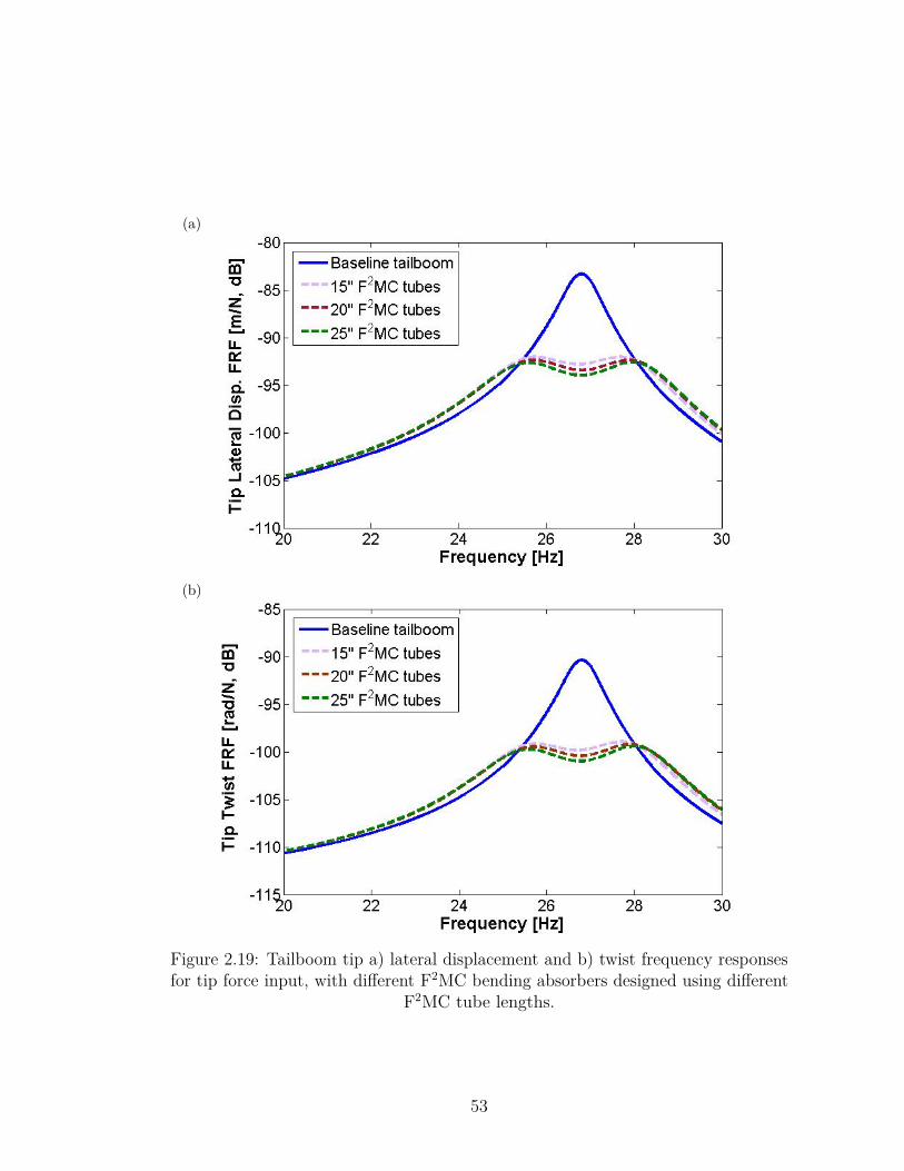
(a)
(b)
Figure 2.19: Tailboom tip a) lateral displacement and b) twist frequency responsesfor tip force input, with different F2MC bending absorbers designed using different
F2MC tube lengths.
53
2.3.4 Summary of Design Study Results
Based on the predicted performance of the different F2MC absorber concepts,the proposed bending absorber is superior to the proposed torsional absorberat reducing vibrations for this particular tailboom mode. The torsional F2MCabsorber concept may be effective for reducing vibrations in structures with lowtorsional stiffness or mode shapes containing more torsional deformation. However,the laboratory-scale tailboom seems unsuitable for verifying the performance ofthis particular absorber concept. Simulation results predict that F2MC bendingabsorbers can reduce both bending and torsional vibration by around 70% for atarget coupled mode of this laboratory-scale tailboom.
The model predicts that this level of vibration reduction can be achieved usinga variety of F2MC tube lengths and inertia track dimensions, which providesflexibility in how an F2MC treatment can be designed to meet different objectives.Shortening the F2MC tubes or using a narrower inertia track radius may reduce theweight and/or size of the treatment without significantly reducing the treatmenteffectiveness.
54
Chapter 3 |Experimental Demonstrationof Tailboom Lateral Bending/Torsion Mode Control
In this chapter, experimental results are presented to verify the model described inChapter 2 for coupled pairs of tubes pumping through the same fluidic circuit. Aset of four F2MC tubes is fabricated and attached to the laboratory-scale tailboomalong with fluidic circuits designed using the model. To assess the F2MC absorbereffectiveness, the resulting vibration frequency responses are measured with a laservibrometer and accelerometers. The model accuracy is verified by experiments usingseveral different fluidic circuit designs. Circuits utilizing two different fluids (waterand a high-density, low-viscosity fluid) and two different tubing materials (copperand plastic) are tested. With proper tuning, all of these circuits are demonstratedsuccessfully and exhibit similar performance.
3.1 Fabrication of F2MC TubesThe braided-sheath F2MC tubes fabricated for the prototype absorber are similarto those used by Miura in [74]. The tubes use a 1/32 in. thick, 3/8 in. inner diameterlatex rubber bladder reinforced by a corrosion-resistant stainless steel mesh. Athin bladder is chosen to minimize the effects of wall compliance in the F2MCtube. Thicker bladders increase tube capacitance c4, which can limit the absorbereffectiveness but may also drive required inertia track lengths down. In experiments,
55
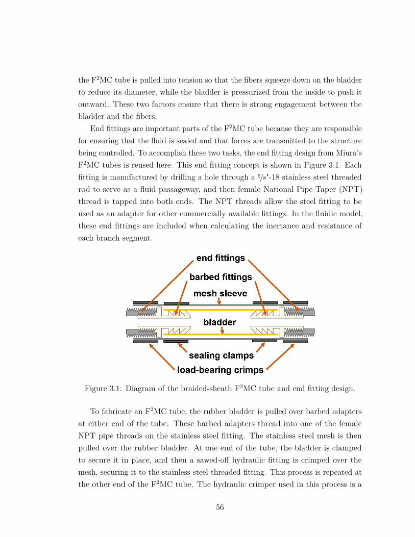
the F2MC tube is pulled into tension so that the fibers squeeze down on the bladderto reduce its diameter, while the bladder is pressurized from the inside to push itoutward. These two factors ensure that there is strong engagement between thebladder and the fibers.
End fittings are important parts of the F2MC tube because they are responsiblefor ensuring that the fluid is sealed and that forces are transmitted to the structurebeing controlled. To accomplish these two tasks, the end fitting design from Miura’sF2MC tubes is reused here. This end fitting concept is shown in Figure 3.1. Eachfitting is manufactured by drilling a hole through a 5/8"-18 stainless steel threadedrod to serve as a fluid passageway, and then female National Pipe Taper (NPT)thread is tapped into both ends. The NPT threads allow the steel fitting to beused as an adapter for other commercially available fittings. In the fluidic model,these end fittings are included when calculating the inertance and resistance ofeach branch segment.
Figure 3.1: Diagram of the braided-sheath F2MC tube and end fitting design.
To fabricate an F2MC tube, the rubber bladder is pulled over barbed adaptersat either end of the tube. These barbed adapters thread into one of the femaleNPT pipe threads on the stainless steel fitting. The stainless steel mesh is thenpulled over the rubber bladder. At one end of the tube, the bladder is clampedto secure it in place, and then a sawed-off hydraulic fitting is crimped over themesh, securing it to the stainless steel threaded fitting. This process is repeated atthe other end of the F2MC tube. The hydraulic crimper used in this process is a
56
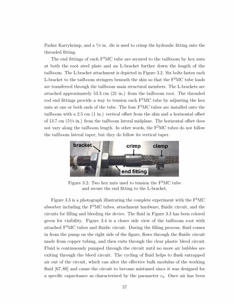
Parker Karrykrimp, and a 5/8 in. die is used to crimp the hydraulic fitting onto thethreaded fitting.
The end fittings of each F2MC tube are secured to the tailboom by hex nutsat both the root steel plate and an L-bracket further down the length of thetailboom. The L-bracket attachment is depicted in Figure 3.2. Six bolts fasten eachL-bracket to the tailboom stringers beneath the skin so that the F2MC tube loadsare transferred through the tailboom main structural members. The L-brackets areattached approximately 53.3 cm (21 in.) from the tailboom root. The threadedrod end fittings provide a way to tension each F2MC tube by adjusting the hexnuts at one or both ends of the tube. The four F2MC tubes are installed onto thetailboom with a 2.5 cm (1 in.) vertical offset from the skin and a horizontal offsetof 13.7 cm (53/8 in.) from the tailboom lateral midplane. The horizontal offset doesnot vary along the tailboom length. In other words, the F2MC tubes do not followthe tailboom lateral taper, but they do follow its vertical taper.
Figure 3.2: Two hex nuts used to tension the F2MC tubeand secure the end fitting to the L-bracket.
Figure 3.3 is a photograph illustrating the complete experiment with the F2MCabsorber including the F2MC tubes, attachment hardware, fluidic circuit, and thecircuits for filling and bleeding the device. The fluid in Figure 3.3 has been coloredgreen for visibility. Figure 3.4 is a closer side view of the tailboom root withattached F2MC tubes and fluidic circuit. During the filling process, fluid comesin from the pump on the right side of the figure, flows through the fluidic circuitmade from copper tubing, and then exits through the clear plastic bleed circuit.Fluid is continuously pumped through the circuit until no more air bubbles areexiting through the bleed circuit. The cycling of fluid helps to flush entrappedair out of the circuit, which can alter the effective bulk modulus of the workingfluid [67, 80] and cause the circuit to become mistuned since it was designed fora specific capacitance as characterized by the parameter c4. Once air has been
57
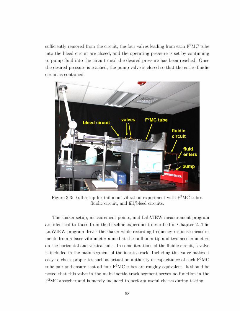
sufficiently removed from the circuit, the four valves leading from each F2MC tubeinto the bleed circuit are closed, and the operating pressure is set by continuingto pump fluid into the circuit until the desired pressure has been reached. Oncethe desired pressure is reached, the pump valve is closed so that the entire fluidiccircuit is contained.
Figure 3.3: Full setup for tailboom vibration experiment with F2MC tubes,fluidic circuit, and fill/bleed circuits.
The shaker setup, measurement points, and LabVIEW measurement programare identical to those from the baseline experiment described in Chapter 2. TheLabVIEW program drives the shaker while recording frequency response measure-ments from a laser vibrometer aimed at the tailboom tip and two accelerometerson the horizontal and vertical tails. In some iterations of the fluidic circuit, a valveis included in the main segment of the inertia track. Including this valve makes iteasy to check properties such as actuation authority or capacitance of each F2MCtube pair and ensure that all four F2MC tubes are roughly equivalent. It should benoted that this valve in the main inertia track segment serves no function in theF2MC absorber and is merely included to perform useful checks during testing.
58
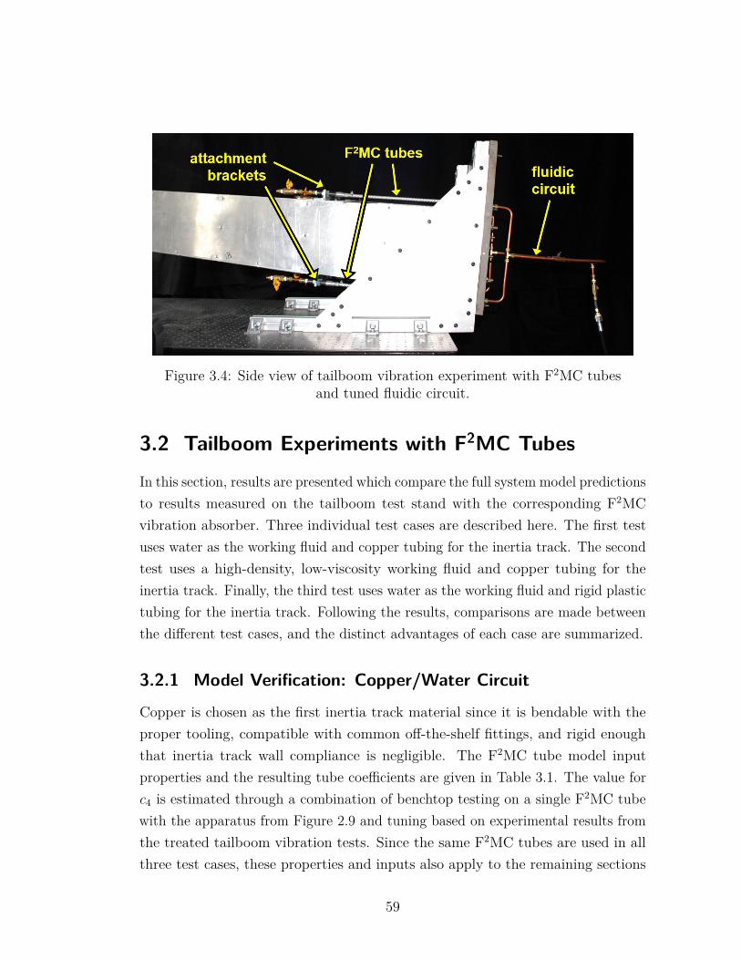
Figure 3.4: Side view of tailboom vibration experiment with F2MC tubesand tuned fluidic circuit.
3.2 Tailboom Experiments with F2MC TubesIn this section, results are presented which compare the full system model predictionsto results measured on the tailboom test stand with the corresponding F2MCvibration absorber. Three individual test cases are described here. The first testuses water as the working fluid and copper tubing for the inertia track. The secondtest uses a high-density, low-viscosity working fluid and copper tubing for theinertia track. Finally, the third test uses water as the working fluid and rigid plastictubing for the inertia track. Following the results, comparisons are made betweenthe different test cases, and the distinct advantages of each case are summarized.
3.2.1 Model Verification: Copper/Water Circuit
Copper is chosen as the first inertia track material since it is bendable with theproper tooling, compatible with common off-the-shelf fittings, and rigid enoughthat inertia track wall compliance is negligible. The F2MC tube model inputproperties and the resulting tube coefficients are given in Table 3.1. The value forc4 is estimated through a combination of benchtop testing on a single F2MC tubewith the apparatus from Figure 2.9 and tuning based on experimental results fromthe treated tailboom vibration tests. Since the same F2MC tubes are used in allthree test cases, these properties and inputs also apply to the remaining sections
59
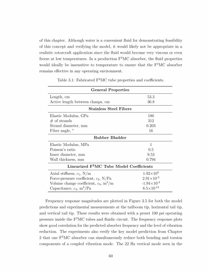
of this chapter. Although water is a convenient fluid for demonstrating feasibilityof this concept and verifying the model, it would likely not be appropriate in arealistic rotorcraft application since the fluid would become very viscous or evenfreeze at low temperatures. In a production F2MC absorber, the fluid propertieswould ideally be insensitive to temperature to ensure that the F2MC absorberremains effective in any operating environment.
Table 3.1: Fabricated F2MC tube properties and coefficients.
General Properties
Length, cm 53.3Active length between clamps, cm 36.8
Stainless Steel Fibers
Elastic Modulus, GPa 180# of strands 312Strand diameter, mm 0.203Fiber angle, ° 16
Rubber Bladder
Elastic Modulus, MPa 1Poisson’s ratio 0.5Inner diameter, mm 9.53Wall thickness, mm 0.794
Linearized F2MC Tube Model Coefficients
Axial stiffness, c1, N/m 1.92×10⁴
Force-pressure coefficient, c2, N/Pa 2.91×10⁻³
Volume change coefficient, c3, m3/m -1.94×10⁻³
Capacitance, c4, m3/Pa 8.5×10⁻¹³
Frequency response magnitudes are plotted in Figure 3.5 for both the modelpredictions and experimental measurements at the tailboom tip, horizontal tail tip,and vertical tail tip. These results were obtained with a preset 100 psi operatingpressure inside the F2MC tubes and fluidic circuit. The frequency response plotsshow good correlation for the predicted absorber frequency and the level of vibrationreduction. The experiments also verify the key model prediction from Chapter2 that one F2MC absorber can simultaneously reduce both bending and torsioncomponents of a coupled vibration mode. The 22 Hz vertical mode seen in the
60
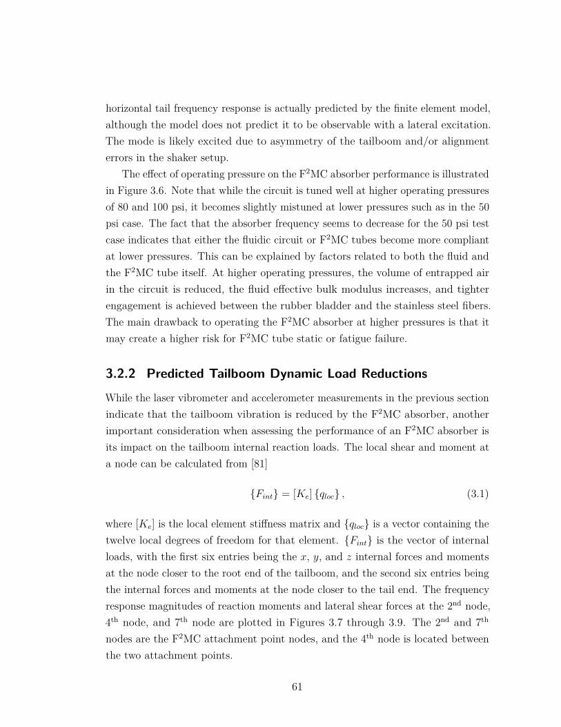
horizontal tail frequency response is actually predicted by the finite element model,although the model does not predict it to be observable with a lateral excitation.The mode is likely excited due to asymmetry of the tailboom and/or alignmenterrors in the shaker setup.
The effect of operating pressure on the F2MC absorber performance is illustratedin Figure 3.6. Note that while the circuit is tuned well at higher operating pressuresof 80 and 100 psi, it becomes slightly mistuned at lower pressures such as in the 50psi case. The fact that the absorber frequency seems to decrease for the 50 psi testcase indicates that either the fluidic circuit or F2MC tubes become more compliantat lower pressures. This can be explained by factors related to both the fluid andthe F2MC tube itself. At higher operating pressures, the volume of entrapped airin the circuit is reduced, the fluid effective bulk modulus increases, and tighterengagement is achieved between the rubber bladder and the stainless steel fibers.The main drawback to operating the F2MC absorber at higher pressures is that itmay create a higher risk for F2MC tube static or fatigue failure.
3.2.2 Predicted Tailboom Dynamic Load Reductions
While the laser vibrometer and accelerometer measurements in the previous sectionindicate that the tailboom vibration is reduced by the F2MC absorber, anotherimportant consideration when assessing the performance of an F2MC absorber isits impact on the tailboom internal reaction loads. The local shear and moment ata node can be calculated from [81]
Fint = [Ke] qloc , (3.1)
where [Ke] is the local element stiffness matrix and qloc is a vector containing thetwelve local degrees of freedom for that element. Fint is the vector of internalloads, with the first six entries being the x, y, and z internal forces and momentsat the node closer to the root end of the tailboom, and the second six entries beingthe internal forces and moments at the node closer to the tail end. The frequencyresponse magnitudes of reaction moments and lateral shear forces at the 2nd node,4th node, and 7th node are plotted in Figures 3.7 through 3.9. The 2nd and 7th
nodes are the F2MC attachment point nodes, and the 4th node is located betweenthe two attachment points.
61
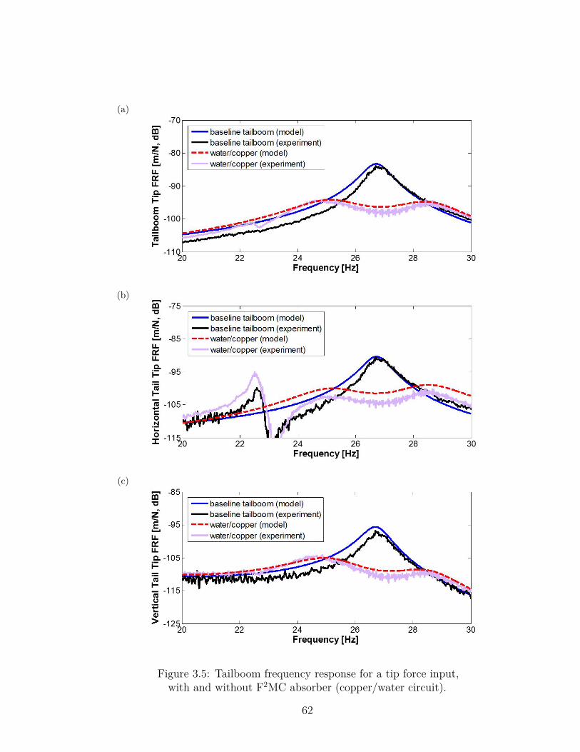
(a)
(b)
(c)
Figure 3.5: Tailboom frequency response for a tip force input,with and without F2MC absorber (copper/water circuit).
62
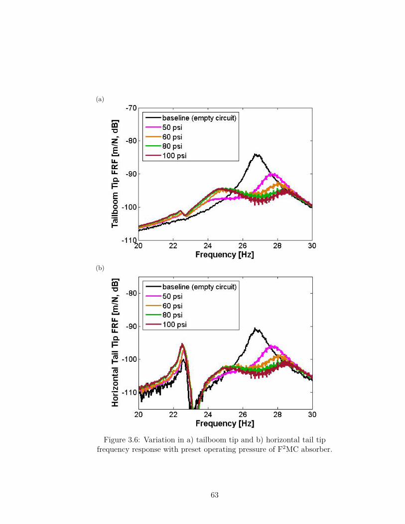
(a)
(b)
Figure 3.6: Variation in a) tailboom tip and b) horizontal tail tipfrequency response with preset operating pressure of F2MC absorber.
63
In general, these internal reaction frequency responses are similar to the displace-ment frequency responses presented in Figure 3.5. The model predicts that evenover the area spanned by the F2MC tubes, internal reaction loads are reduced. Thisis consistent with the results observed by Heverly [76], where an active vibrationcontrol installation reduces the vibratory stresses in the laboratory-scale tailboomcorner stringers. However, Heverly also observed that with the actuator installationactive, stresses in the actuator attachment frames increased locally. Dependingon the complexity of the attachment hardware in a given absorber, the stressesinduced by F2MC tube forces could be estimated using hand calculations or a finiteelement model to ensure that attachment hardware is sized appropriately.
3.2.3 Model Verification: Copper/Dense Fluid Circuit
The second test examines performance of an F2MC absorber using a dense fluidwith viscosity comparable to water. Its properties are representative of a fluid usedin production fluidic vibration isolators, and its specific gravity is approximately1.88. This second circuit is built specifically to investigate the benefits of usinga denser working fluid. Based on Eq. (2.59), the same effective inertance can beachieved in a shorter segment of tubing if a denser working fluid is chosen. Also,if frequency-dependent effects are neglected, Eq. (2.60) indicates that if the sametubing radius is maintained in the new inertia track, it will have a lower resistancebecause of its shorter length.
Figures 3.10 and 3.11 illustrate the difference in track tubing required betweenthe fluidic circuit using water and the fluidic circuit using the denser fluid. Thecircuit using the dense fluid is more compact, which makes denser fluids attractivein applications where space constraints are important. However, the experimentallymeasured frequency response plotted in Figure 3.12 shows similar performance tothe F2MC absorber using water as the working fluid. In fact, the F2MC absorberusing water is slightly more effective than the absorber using the dense fluid. Again,a 100 psi operating pressure is set prior to the test, and there is good correlationbetween model predictions and experimental measurements for both the absorberfrequency and the level of vibration reduction.
64
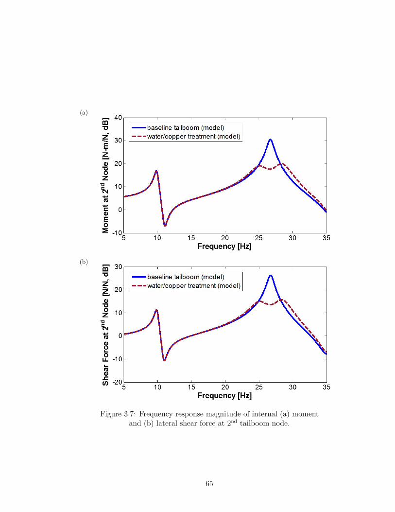
(a)
(b)
Figure 3.7: Frequency response magnitude of internal (a) momentand (b) lateral shear force at 2nd tailboom node.
65
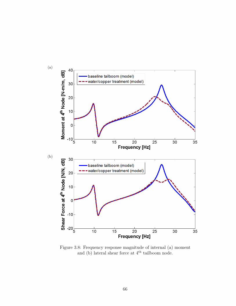
(a)
(b)
Figure 3.8: Frequency response magnitude of internal (a) momentand (b) lateral shear force at 4th tailboom node.
66
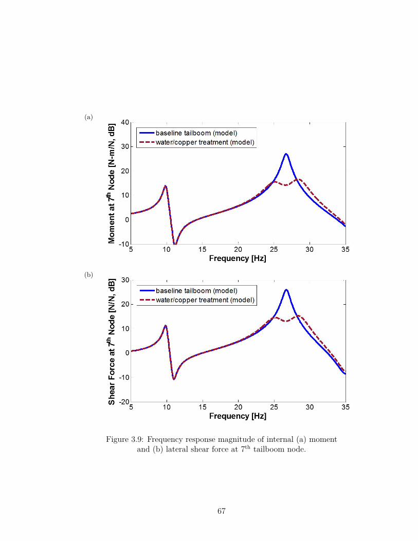
(a)
(b)
Figure 3.9: Frequency response magnitude of internal (a) momentand (b) lateral shear force at 7th tailboom node.
67
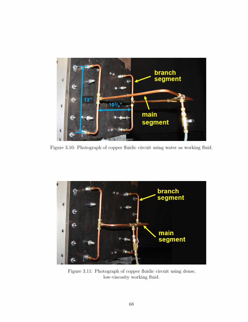
Figure 3.10: Photograph of copper fluidic circuit using water as working fluid.
Figure 3.11: Photograph of copper fluidic circuit using dense,low-viscosity working fluid.
68
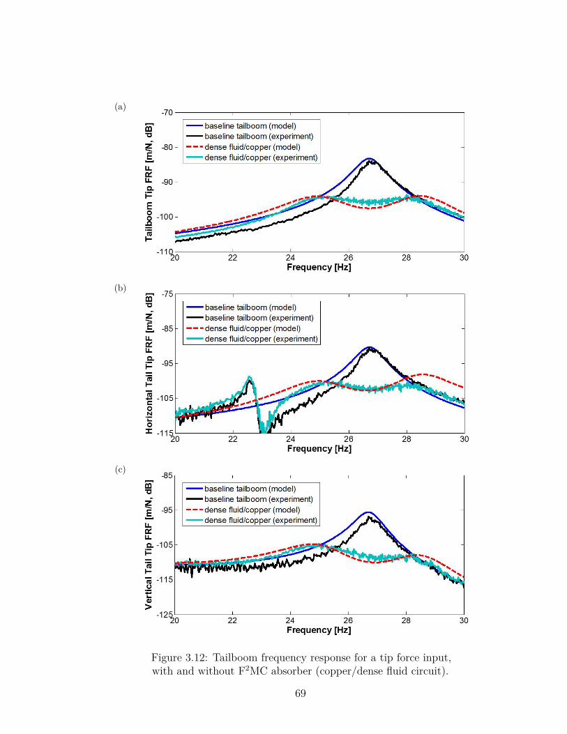
(a)
(b)
(c)
Figure 3.12: Tailboom frequency response for a tip force input,with and without F2MC absorber (copper/dense fluid circuit).
69
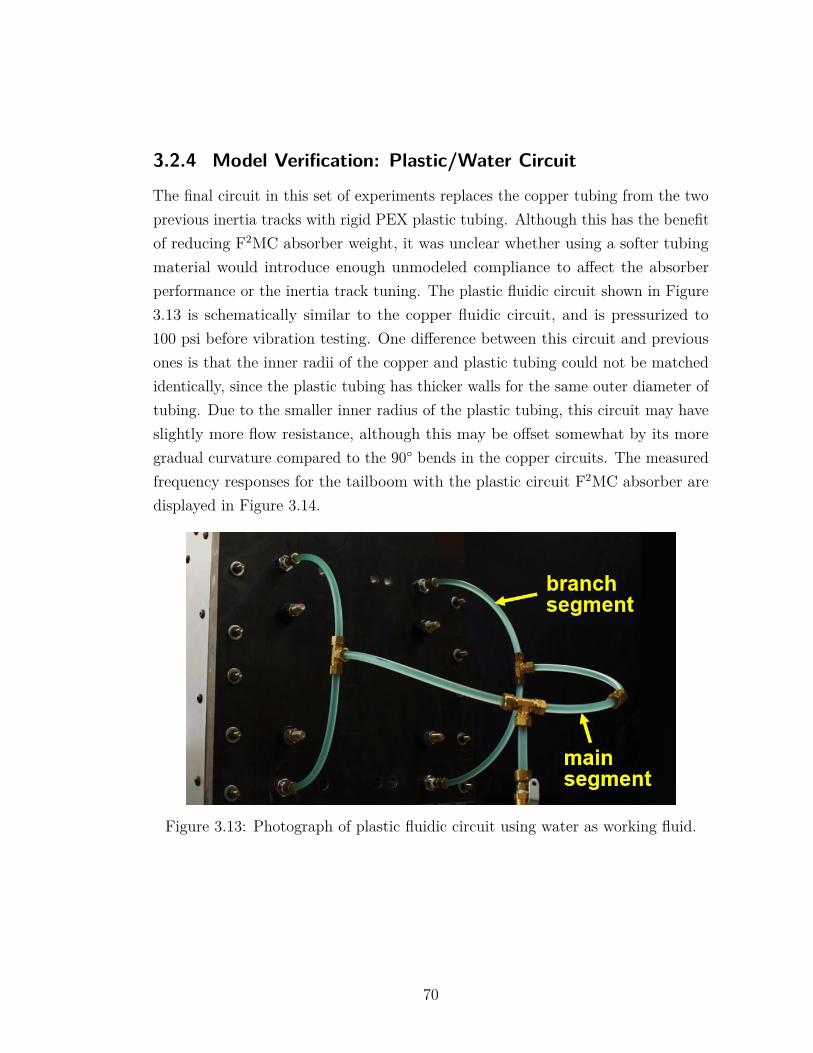
3.2.4 Model Verification: Plastic/Water Circuit
The final circuit in this set of experiments replaces the copper tubing from the twoprevious inertia tracks with rigid PEX plastic tubing. Although this has the benefitof reducing F2MC absorber weight, it was unclear whether using a softer tubingmaterial would introduce enough unmodeled compliance to affect the absorberperformance or the inertia track tuning. The plastic fluidic circuit shown in Figure3.13 is schematically similar to the copper fluidic circuit, and is pressurized to100 psi before vibration testing. One difference between this circuit and previousones is that the inner radii of the copper and plastic tubing could not be matchedidentically, since the plastic tubing has thicker walls for the same outer diameter oftubing. Due to the smaller inner radius of the plastic tubing, this circuit may haveslightly more flow resistance, although this may be offset somewhat by its moregradual curvature compared to the 90° bends in the copper circuits. The measuredfrequency responses for the tailboom with the plastic circuit F2MC absorber aredisplayed in Figure 3.14.
Figure 3.13: Photograph of plastic fluidic circuit using water as working fluid.
70
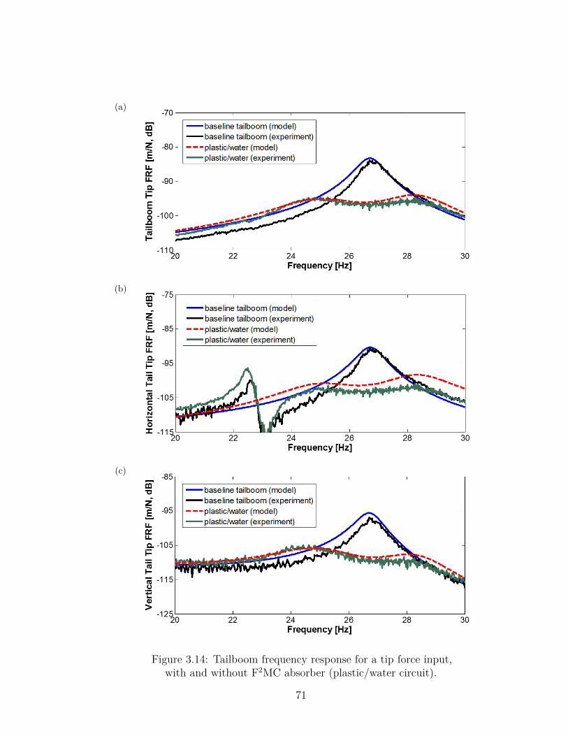
(a)
(b)
(c)
Figure 3.14: Tailboom frequency response for a tip force input,with and without F2MC absorber (plastic/water circuit).
71
3.3 Comparisons & Summary of ResultsWhile it is encouraging that all three F2MC absorbers in the previous sectionproduce appreciable vibration reduction, this section focuses on identifying themain differences between the three absorbers and the results obtained from them.Properties of the three fluidic circuits used in the tests, as well as the correspondingabsorber weight estimates, are contained in Table 3.2. The weights of variousindividual components that contribute to the overall F2MC absorber weight arelisted in Table 3.3. The weights of the two L-brackets are not included in theabsorber weight estimate, as they are considered part of the tailboom structurebeing controlled. Component weights were obtained by weighing each item on abalance scale. It should be noted that across all three absorbers, over half theabsorber weight is fixed due to the stainless steel threaded fittings, valves, andoff-the-shelf compression fittings. For a production application, the weight of thesecomponents could likely be reduced by selecting lighter components intended foruse in aerospace applications.
The frequency response curves for tailboom tip displacement and horizontaltail tip displacement with all three absorbers tested at 100 psi are compiled inFigure 3.15. By defining two metrics to characterize performance, the small gapbetween the results can be quantified. The first metric, notch depth, is definedas the difference between the resonant peak height of the uncontrolled tailboomand the magnitude of the F2MC-controlled displacement frequency response atthe same resonant frequency. The second metric, peak-to-peak depth, measuresthe difference between the uncontrolled peak height and the higher of the twoF2MC-controlled absorber peaks on either side of the tailboom natural frequency.A performance comparison of the three absorbers according to these metrics isprovided in Table 3.4.
72
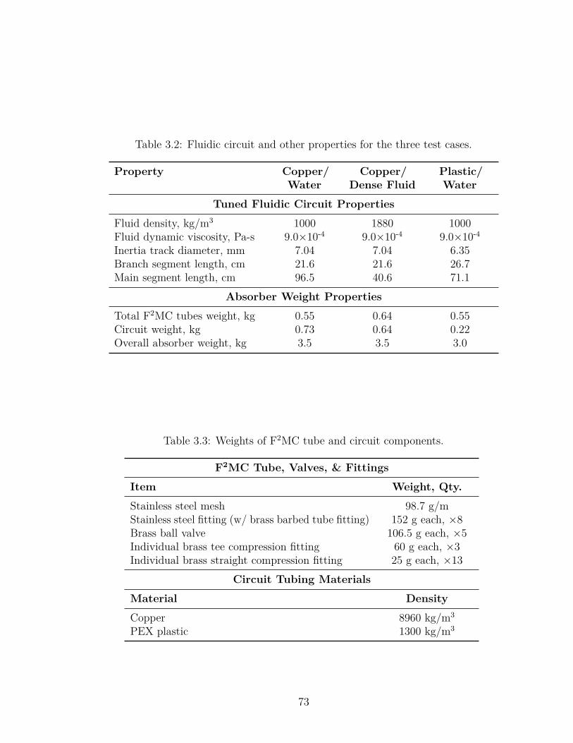
Table 3.2: Fluidic circuit and other properties for the three test cases.
Property Copper/Water
Copper/Dense Fluid
Plastic/Water
Tuned Fluidic Circuit Properties
Fluid density, kg/m3 1000 1880 1000Fluid dynamic viscosity, Pa-s 9.0×10⁻⁴ 9.0×10⁻⁴ 9.0×10⁻⁴
Inertia track diameter, mm 7.04 7.04 6.35Branch segment length, cm 21.6 21.6 26.7Main segment length, cm 96.5 40.6 71.1
Absorber Weight Properties
Total F2MC tubes weight, kg 0.55 0.64 0.55Circuit weight, kg 0.73 0.64 0.22Overall absorber weight, kg 3.5 3.5 3.0
Table 3.3: Weights of F2MC tube and circuit components.
F2MC Tube, Valves, & Fittings
Item Weight, Qty.
Stainless steel mesh 98.7 g/mStainless steel fitting (w/ brass barbed tube fitting) 152 g each, ×8Brass ball valve 106.5 g each, ×5Individual brass tee compression fitting 60 g each, ×3Individual brass straight compression fitting 25 g each, ×13
Circuit Tubing Materials
Material Density
Copper 8960 kg/m3
PEX plastic 1300 kg/m3
73
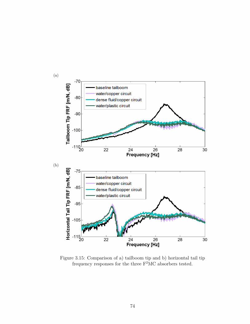
(a)
(b)
Figure 3.15: Comparison of a) tailboom tip and b) horizontal tail tipfrequency responses for the three F2MC absorbers tested.
74
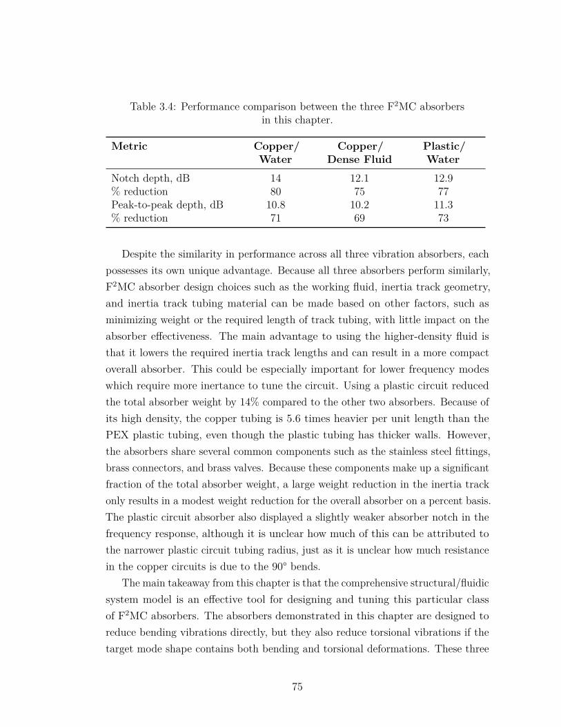
Table 3.4: Performance comparison between the three F2MC absorbersin this chapter.
Metric Copper/Water
Copper/Dense Fluid
Plastic/Water
Notch depth, dB 14 12.1 12.9% reduction 80 75 77Peak-to-peak depth, dB 10.8 10.2 11.3% reduction 71 69 73
Despite the similarity in performance across all three vibration absorbers, eachpossesses its own unique advantage. Because all three absorbers perform similarly,F2MC absorber design choices such as the working fluid, inertia track geometry,and inertia track tubing material can be made based on other factors, such asminimizing weight or the required length of track tubing, with little impact on theabsorber effectiveness. The main advantage to using the higher-density fluid isthat it lowers the required inertia track lengths and can result in a more compactoverall absorber. This could be especially important for lower frequency modeswhich require more inertance to tune the circuit. Using a plastic circuit reducedthe total absorber weight by 14% compared to the other two absorbers. Because ofits high density, the copper tubing is 5.6 times heavier per unit length than thePEX plastic tubing, even though the plastic tubing has thicker walls. However,the absorbers share several common components such as the stainless steel fittings,brass connectors, and brass valves. Because these components make up a significantfraction of the total absorber weight, a large weight reduction in the inertia trackonly results in a modest weight reduction for the overall absorber on a percent basis.The plastic circuit absorber also displayed a slightly weaker absorber notch in thefrequency response, although it is unclear how much of this can be attributed tothe narrower plastic circuit tubing radius, just as it is unclear how much resistancein the copper circuits is due to the 90° bends.
The main takeaway from this chapter is that the comprehensive structural/fluidicsystem model is an effective tool for designing and tuning this particular classof F2MC absorbers. The absorbers demonstrated in this chapter are designed toreduce bending vibrations directly, but they also reduce torsional vibrations if thetarget mode shape contains both bending and torsional deformations. These three
75
F2MC absorbers are demonstrated on a 26.7 Hz lateral bending/torsion mode,making this the highest frequency for which an F2MC absorber has been successfullydesigned and tested on a continuous structure. All three F2MC absorbers testedreduced vibrations by over 75% at this 26.7 Hz mode, resulting in similar frequencyresponses and levels of vibration reduction.
These experimental results are also important because they are the first demon-stration of F2MC vibration control on a representative aerospace structure using aworking fluid other than the dense isolator fluid, as Miura did not test his absorberwith other fluids [74]. Being able to obtain similar performance using a relativelycommon fluid such as water as opposed to a specialized, dense fluid could signif-icantly reduce the cost of an F2MC absorber or make it easier for companies todevelop F2MC vibration absorbers in the future.
76
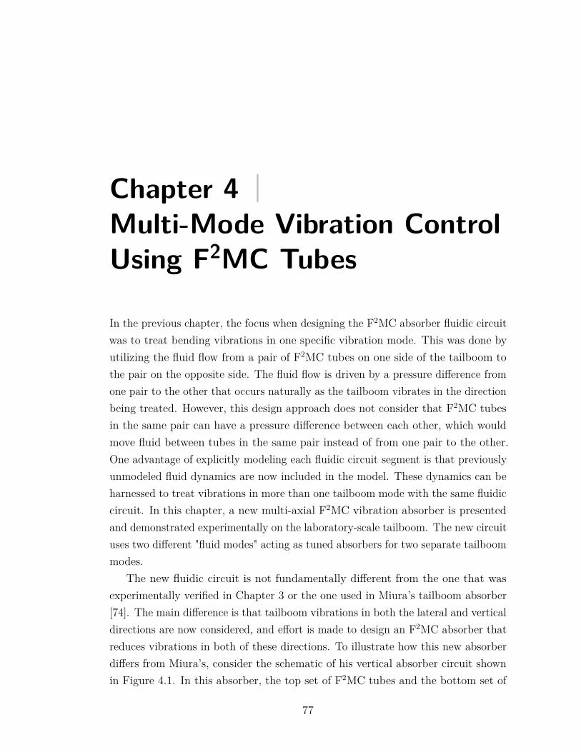
Chapter 4 |Multi-Mode Vibration ControlUsing F2MC Tubes
In the previous chapter, the focus when designing the F2MC absorber fluidic circuitwas to treat bending vibrations in one specific vibration mode. This was done byutilizing the fluid flow from a pair of F2MC tubes on one side of the tailboom tothe pair on the opposite side. The fluid flow is driven by a pressure difference fromone pair to the other that occurs naturally as the tailboom vibrates in the directionbeing treated. However, this design approach does not consider that F2MC tubesin the same pair can have a pressure difference between each other, which wouldmove fluid between tubes in the same pair instead of from one pair to the other.One advantage of explicitly modeling each fluidic circuit segment is that previouslyunmodeled fluid dynamics are now included in the model. These dynamics can beharnessed to treat vibrations in more than one tailboom mode with the same fluidiccircuit. In this chapter, a new multi-axial F2MC vibration absorber is presentedand demonstrated experimentally on the laboratory-scale tailboom. The new circuituses two different "fluid modes" acting as tuned absorbers for two separate tailboommodes.
The new fluidic circuit is not fundamentally different from the one that wasexperimentally verified in Chapter 3 or the one used in Miura’s tailboom absorber[74]. The main difference is that tailboom vibrations in both the lateral and verticaldirections are now considered, and effort is made to design an F2MC absorber thatreduces vibrations in both of these directions. To illustrate how this new absorberdiffers from Miura’s, consider the schematic of his vertical absorber circuit shownin Figure 4.1. In this absorber, the top set of F2MC tubes and the bottom set of
77
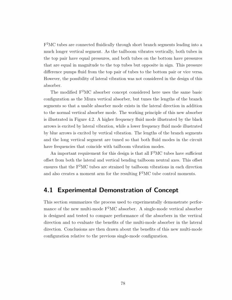
F2MC tubes are connected fluidically through short branch segments leading into amuch longer vertical segment. As the tailboom vibrates vertically, both tubes inthe top pair have equal pressures, and both tubes on the bottom have pressuresthat are equal in magnitude to the top tubes but opposite in sign. This pressuredifference pumps fluid from the top pair of tubes to the bottom pair or vice versa.However, the possibility of lateral vibration was not considered in the design of thisabsorber.
The modified F2MC absorber concept considered here uses the same basicconfiguration as the Miura vertical absorber, but tunes the lengths of the branchsegments so that a usable absorber mode exists in the lateral direction in additionto the normal vertical absorber mode. The working principle of this new absorberis illustrated in Figure 4.2. A higher frequency fluid mode illustrated by the blackarrows is excited by lateral vibration, while a lower frequency fluid mode illustratedby blue arrows is excited by vertical vibration. The lengths of the branch segmentsand the long vertical segment are tuned so that both fluid modes in the circuithave frequencies that coincide with tailboom vibration modes.
An important requirement for this design is that all F2MC tubes have sufficientoffset from both the lateral and vertical bending tailboom neutral axes. This offsetensures that the F2MC tubes are strained by tailboom vibrations in each directionand also creates a moment arm for the resulting F2MC tube control moments.
4.1 Experimental Demonstration of ConceptThis section summarizes the process used to experimentally demonstrate perfor-mance of the new multi-mode F2MC absorber. A single-mode vertical absorberis designed and tested to compare performance of the absorbers in the verticaldirection and to evaluate the benefits of the multi-mode absorber in the lateraldirection. Conclusions are then drawn about the benefits of this new multi-modeconfiguration relative to the previous single-mode configuration.
78
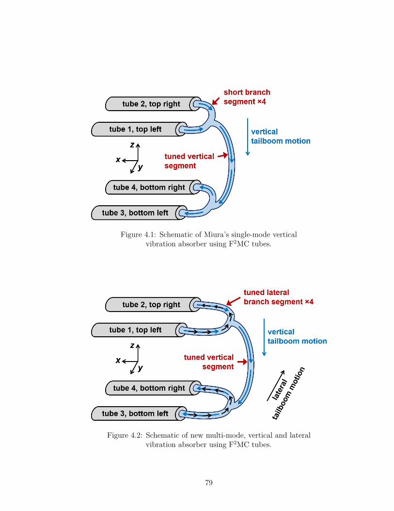
Figure 4.1: Schematic of Miura’s single-mode verticalvibration absorber using F2MC tubes.
Figure 4.2: Schematic of new multi-mode, vertical and lateralvibration absorber using F2MC tubes.
79
4.1.1 Single-Mode Vertical F2MC Absorber
The single-mode vertical F2MC absorber uses the same F2MC tubes and tubelocations from the lateral bending/torsion mode absorbers in Chapter 3. However,the tube pairs are connected vertically by the fluidic circuit instead of laterally,because the 12.2 Hz vertical tailboom mode has a lower frequency than the 26.7Hz lateral mode. Connecting the F2MC tubes with a vertical track segment as inFigure 4.2 ensures that the vertical fluid mode has a lower absorber frequency thanthe lateral fluid mode in the resulting multi-mode absorber. Each pair of F2MCtubes has 27.3 cm (103/4 in.) of horizontal separation, although theoretically, onlythe F2MC tube offset from the vertical bending plane is important for reducingvertical vibrations. As in the absorbers tested in Chapter 3, each F2MC tube isoffset 2.5 cm (1 in.) vertically from the skin as shown in Figure 4.3.
Figure 4.3: Positioning of F2MC tubes for single-mode and multi-modevibration absorbers. Only the top set of F2MC tubes are shown here, but the
configuration is both vertically and laterally symmetric.
In this single-mode vertical absorber, the fluidic circuit branch segments aremade as short as possible, which has two main effects. First, making the branchsegments shorter reduces the total length of tubing required in the inertia track.Constructing the inertia track with a slightly longer vertical segment to compensatefor shorter branches is more weight-efficient, since the vertical segment combinesflow from both F2MC tubes in each pair and therefore contributes more to theoverall inertia in the vertical direction. Second, using short branch segments keepsthe lateral fluid mode frequency higher than the tailboom natural frequencies byensuring that the effective fluid inertia in the lateral direction is low. Because thecircuit is not properly tuned for a tailboom lateral vibration mode, this particulartreatment is less effective at reducing vibration in the lateral direction. Until this
80
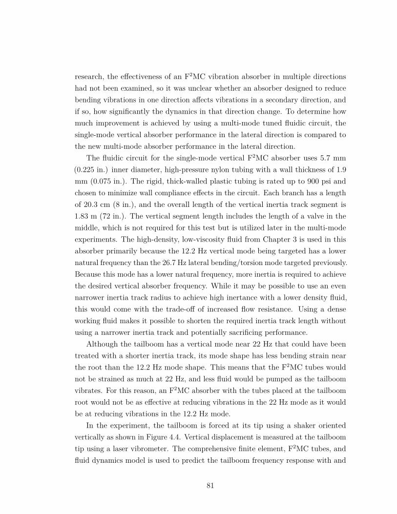
research, the effectiveness of an F2MC vibration absorber in multiple directionshad not been examined, so it was unclear whether an absorber designed to reducebending vibrations in one direction affects vibrations in a secondary direction, andif so, how significantly the dynamics in that direction change. To determine howmuch improvement is achieved by using a multi-mode tuned fluidic circuit, thesingle-mode vertical absorber performance in the lateral direction is compared tothe new multi-mode absorber performance in the lateral direction.
The fluidic circuit for the single-mode vertical F2MC absorber uses 5.7 mm(0.225 in.) inner diameter, high-pressure nylon tubing with a wall thickness of 1.9mm (0.075 in.). The rigid, thick-walled plastic tubing is rated up to 900 psi andchosen to minimize wall compliance effects in the circuit. Each branch has a lengthof 20.3 cm (8 in.), and the overall length of the vertical inertia track segment is1.83 m (72 in.). The vertical segment length includes the length of a valve in themiddle, which is not required for this test but is utilized later in the multi-modeexperiments. The high-density, low-viscosity fluid from Chapter 3 is used in thisabsorber primarily because the 12.2 Hz vertical mode being targeted has a lowernatural frequency than the 26.7 Hz lateral bending/torsion mode targeted previously.Because this mode has a lower natural frequency, more inertia is required to achievethe desired vertical absorber frequency. While it may be possible to use an evennarrower inertia track radius to achieve high inertance with a lower density fluid,this would come with the trade-off of increased flow resistance. Using a denseworking fluid makes it possible to shorten the required inertia track length withoutusing a narrower inertia track and potentially sacrificing performance.
Although the tailboom has a vertical mode near 22 Hz that could have beentreated with a shorter inertia track, its mode shape has less bending strain nearthe root than the 12.2 Hz mode shape. This means that the F2MC tubes wouldnot be strained as much at 22 Hz, and less fluid would be pumped as the tailboomvibrates. For this reason, an F2MC absorber with the tubes placed at the tailboomroot would not be as effective at reducing vibrations in the 22 Hz mode as it wouldbe at reducing vibrations in the 12.2 Hz mode.
In the experiment, the tailboom is forced at its tip using a shaker orientedvertically as shown in Figure 4.4. Vertical displacement is measured at the tailboomtip using a laser vibrometer. The comprehensive finite element, F2MC tubes, andfluid dynamics model is used to predict the tailboom frequency response with and
81
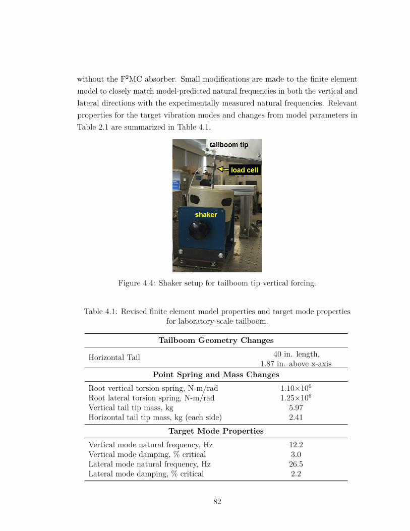
without the F2MC absorber. Small modifications are made to the finite elementmodel to closely match model-predicted natural frequencies in both the vertical andlateral directions with the experimentally measured natural frequencies. Relevantproperties for the target vibration modes and changes from model parameters inTable 2.1 are summarized in Table 4.1.
Figure 4.4: Shaker setup for tailboom tip vertical forcing.
Table 4.1: Revised finite element model properties and target mode propertiesfor laboratory-scale tailboom.
Tailboom Geometry Changes
Horizontal Tail 40 in. length,1.87 in. above x-axis
Point Spring and Mass Changes
Root vertical torsion spring, N-m/rad 1.10×10⁶
Root lateral torsion spring, N-m/rad 1.25×10⁶
Vertical tail tip mass, kg 5.97Horizontal tail tip mass, kg (each side) 2.41
Target Mode Properties
Vertical mode natural frequency, Hz 12.2Vertical mode damping, % critical 3.0Lateral mode natural frequency, Hz 26.5Lateral mode damping, % critical 2.2
82
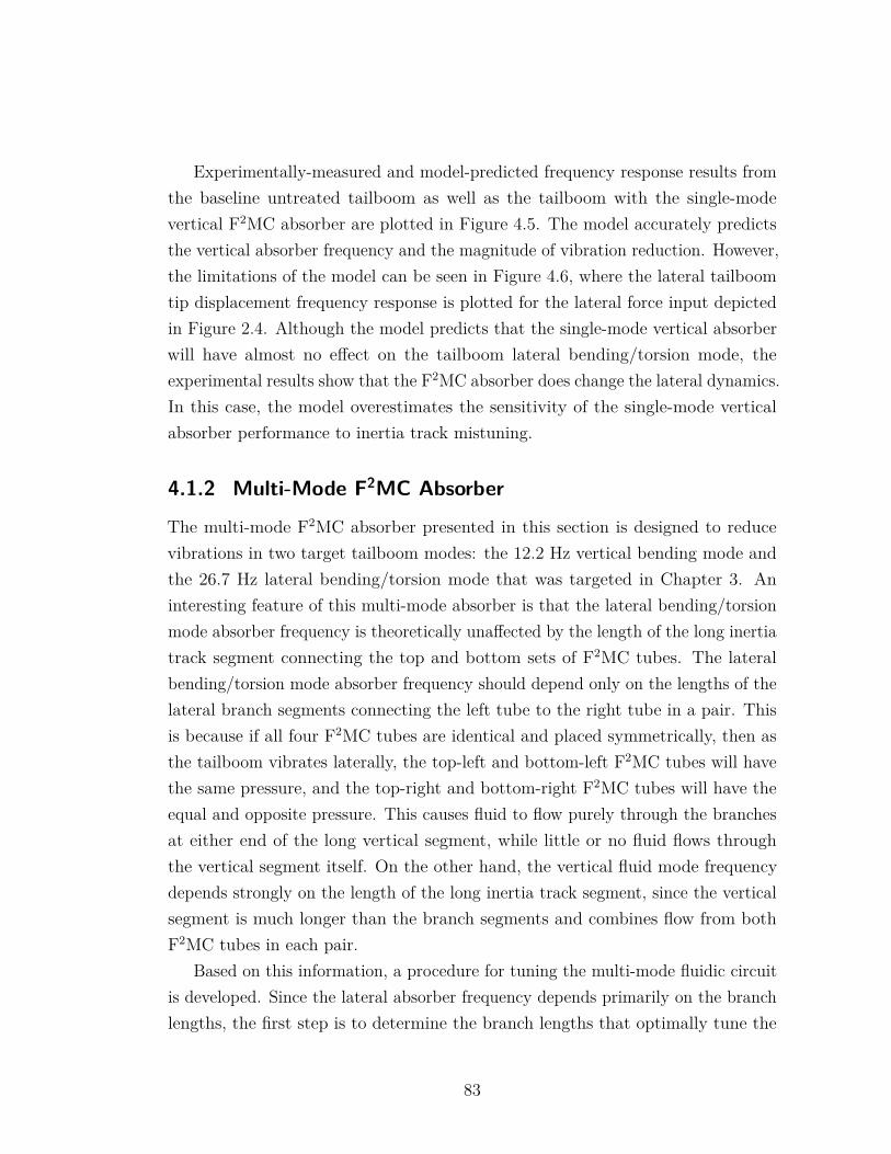
Experimentally-measured and model-predicted frequency response results fromthe baseline untreated tailboom as well as the tailboom with the single-modevertical F2MC absorber are plotted in Figure 4.5. The model accurately predictsthe vertical absorber frequency and the magnitude of vibration reduction. However,the limitations of the model can be seen in Figure 4.6, where the lateral tailboomtip displacement frequency response is plotted for the lateral force input depictedin Figure 2.4. Although the model predicts that the single-mode vertical absorberwill have almost no effect on the tailboom lateral bending/torsion mode, theexperimental results show that the F2MC absorber does change the lateral dynamics.In this case, the model overestimates the sensitivity of the single-mode verticalabsorber performance to inertia track mistuning.
4.1.2 Multi-Mode F2MC Absorber
The multi-mode F2MC absorber presented in this section is designed to reducevibrations in two target tailboom modes: the 12.2 Hz vertical bending mode andthe 26.7 Hz lateral bending/torsion mode that was targeted in Chapter 3. Aninteresting feature of this multi-mode absorber is that the lateral bending/torsionmode absorber frequency is theoretically unaffected by the length of the long inertiatrack segment connecting the top and bottom sets of F2MC tubes. The lateralbending/torsion mode absorber frequency should depend only on the lengths of thelateral branch segments connecting the left tube to the right tube in a pair. Thisis because if all four F2MC tubes are identical and placed symmetrically, then asthe tailboom vibrates laterally, the top-left and bottom-left F2MC tubes will havethe same pressure, and the top-right and bottom-right F2MC tubes will have theequal and opposite pressure. This causes fluid to flow purely through the branchesat either end of the long vertical segment, while little or no fluid flows throughthe vertical segment itself. On the other hand, the vertical fluid mode frequencydepends strongly on the length of the long inertia track segment, since the verticalsegment is much longer than the branch segments and combines flow from bothF2MC tubes in each pair.
Based on this information, a procedure for tuning the multi-mode fluidic circuitis developed. Since the lateral absorber frequency depends primarily on the branchlengths, the first step is to determine the branch lengths that optimally tune the
83
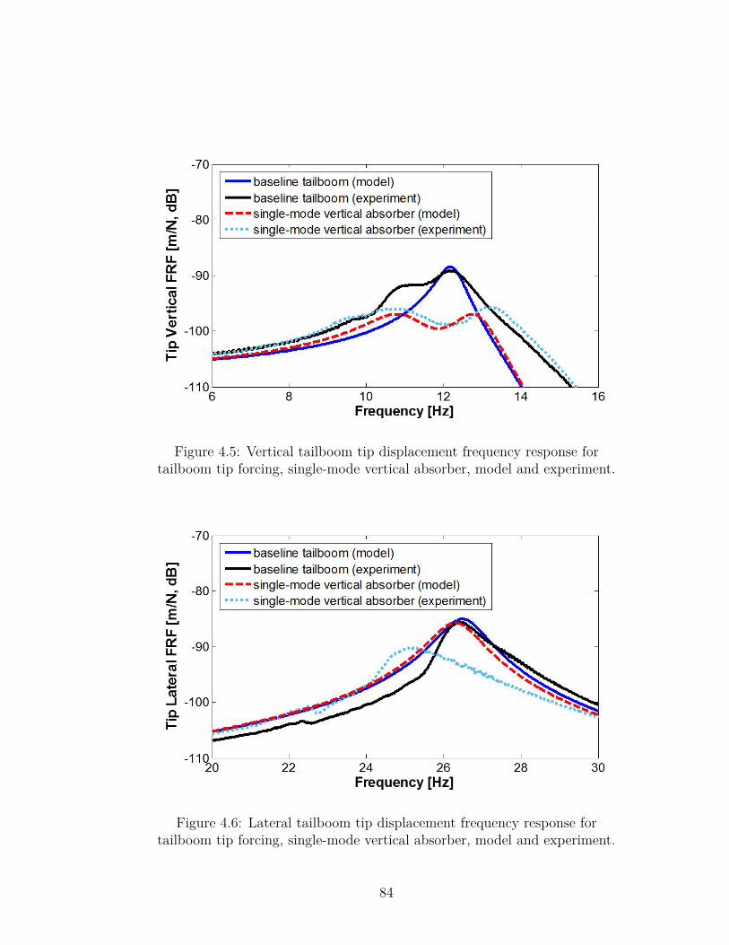
Figure 4.5: Vertical tailboom tip displacement frequency response fortailboom tip forcing, single-mode vertical absorber, model and experiment.
Figure 4.6: Lateral tailboom tip displacement frequency response fortailboom tip forcing, single-mode vertical absorber, model and experiment.
84
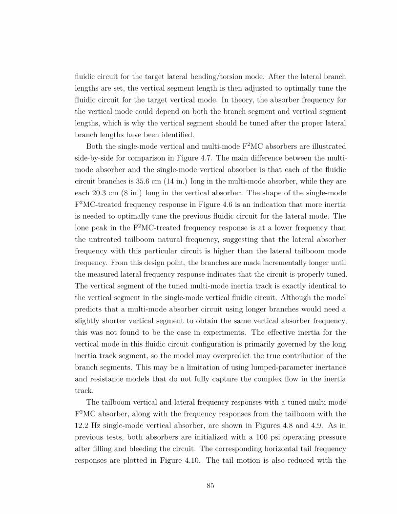
fluidic circuit for the target lateral bending/torsion mode. After the lateral branchlengths are set, the vertical segment length is then adjusted to optimally tune thefluidic circuit for the target vertical mode. In theory, the absorber frequency forthe vertical mode could depend on both the branch segment and vertical segmentlengths, which is why the vertical segment should be tuned after the proper lateralbranch lengths have been identified.
Both the single-mode vertical and multi-mode F2MC absorbers are illustratedside-by-side for comparison in Figure 4.7. The main difference between the multi-mode absorber and the single-mode vertical absorber is that each of the fluidiccircuit branches is 35.6 cm (14 in.) long in the multi-mode absorber, while they areeach 20.3 cm (8 in.) long in the vertical absorber. The shape of the single-modeF2MC-treated frequency response in Figure 4.6 is an indication that more inertiais needed to optimally tune the previous fluidic circuit for the lateral mode. Thelone peak in the F2MC-treated frequency response is at a lower frequency thanthe untreated tailboom natural frequency, suggesting that the lateral absorberfrequency with this particular circuit is higher than the lateral tailboom modefrequency. From this design point, the branches are made incrementally longer untilthe measured lateral frequency response indicates that the circuit is properly tuned.The vertical segment of the tuned multi-mode inertia track is exactly identical tothe vertical segment in the single-mode vertical fluidic circuit. Although the modelpredicts that a multi-mode absorber circuit using longer branches would need aslightly shorter vertical segment to obtain the same vertical absorber frequency,this was not found to be the case in experiments. The effective inertia for thevertical mode in this fluidic circuit configuration is primarily governed by the longinertia track segment, so the model may overpredict the true contribution of thebranch segments. This may be a limitation of using lumped-parameter inertanceand resistance models that do not fully capture the complex flow in the inertiatrack.
The tailboom vertical and lateral frequency responses with a tuned multi-modeF2MC absorber, along with the frequency responses from the tailboom with the12.2 Hz single-mode vertical absorber, are shown in Figures 4.8 and 4.9. As inprevious tests, both absorbers are initialized with a 100 psi operating pressureafter filling and bleeding the circuit. The corresponding horizontal tail frequencyresponses are plotted in Figure 4.10. The tail motion is also reduced with the
85
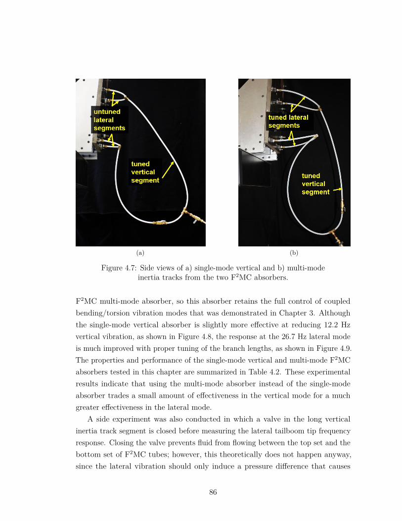
(a) (b)
Figure 4.7: Side views of a) single-mode vertical and b) multi-modeinertia tracks from the two F2MC absorbers.
F2MC multi-mode absorber, so this absorber retains the full control of coupledbending/torsion vibration modes that was demonstrated in Chapter 3. Althoughthe single-mode vertical absorber is slightly more effective at reducing 12.2 Hzvertical vibration, as shown in Figure 4.8, the response at the 26.7 Hz lateral modeis much improved with proper tuning of the branch lengths, as shown in Figure 4.9.The properties and performance of the single-mode vertical and multi-mode F2MCabsorbers tested in this chapter are summarized in Table 4.2. These experimentalresults indicate that using the multi-mode absorber instead of the single-modeabsorber trades a small amount of effectiveness in the vertical mode for a muchgreater effectiveness in the lateral mode.
A side experiment was also conducted in which a valve in the long verticalinertia track segment is closed before measuring the lateral tailboom tip frequencyresponse. Closing the valve prevents fluid from flowing between the top set and thebottom set of F2MC tubes; however, this theoretically does not happen anyway,since the lateral vibration should only induce a pressure difference that causes
86
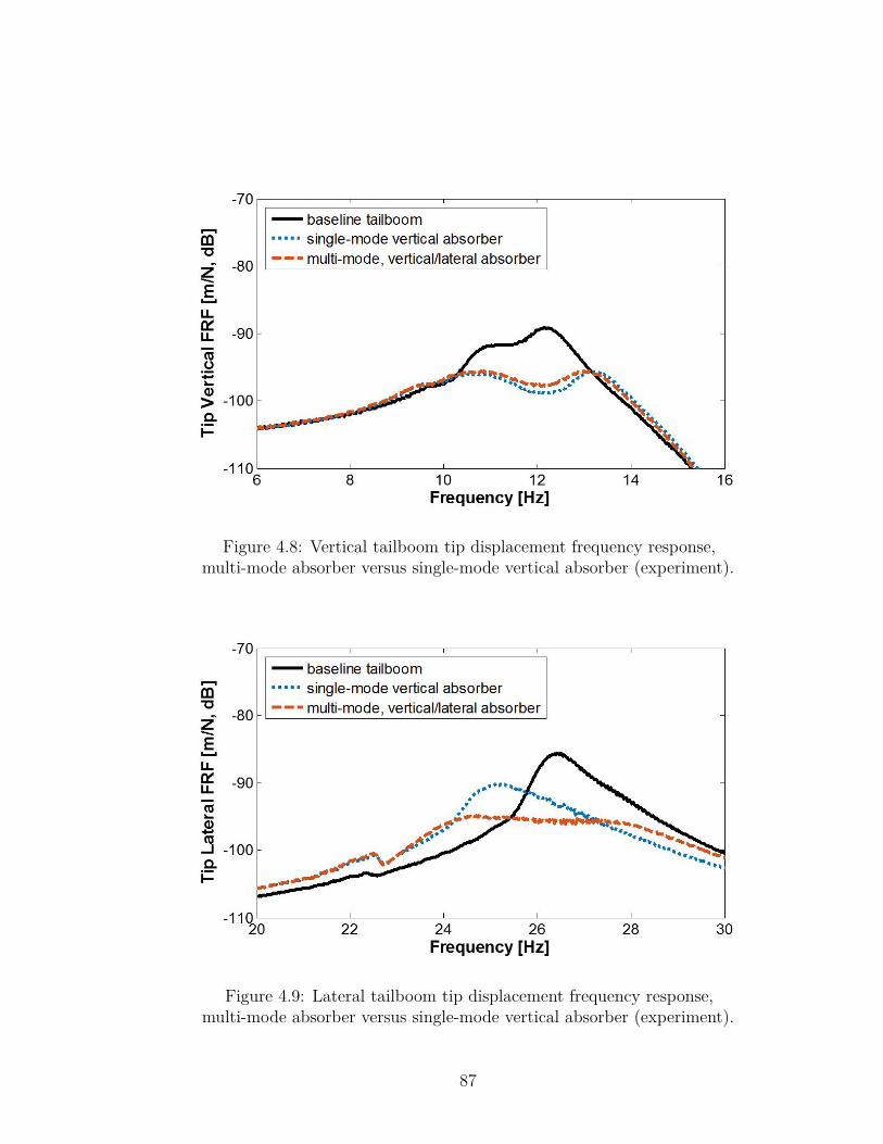
Figure 4.8: Vertical tailboom tip displacement frequency response,multi-mode absorber versus single-mode vertical absorber (experiment).
Figure 4.9: Lateral tailboom tip displacement frequency response,multi-mode absorber versus single-mode vertical absorber (experiment).
87
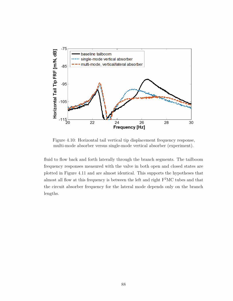
Figure 4.10: Horizontal tail vertical tip displacement frequency response,multi-mode absorber versus single-mode vertical absorber (experiment).
fluid to flow back and forth laterally through the branch segments. The tailboomfrequency responses measured with the valve in both open and closed states areplotted in Figure 4.11 and are almost identical. This supports the hypotheses thatalmost all flow at this frequency is between the left and right F2MC tubes and thatthe circuit absorber frequency for the lateral mode depends only on the branchlengths.
88

Table 4.2: Comparison between single-mode vertical andmulti-mode F2MC absorbers.
Tuned Fluidic Circuit Properties
Property Single-ModeVertical
Multi-ModeVertical/Lateral
Fluid density, kg/m3 1880Inertia track radius, mm 5.7 5.7Branch segment length, cm 20.3 35.6Vertical segment length, m 1.83 1.83
Performance
Metric Single-ModeVertical
Multi-ModeVertical/Lateral
Vertical notch depth, dB 9.8 8.2% reduction 68 63Vertical peak-to-peak depth, dB 6.6 6.6% reduction 53 53Lateral notch depth, dB N/A 10.2% reduction N/A 69Lateral peak-to-peak depth, dB 4.7 9.2% reduction 42 65
4.1.3 Weight Analysis of Single-Mode & Multi-ModeAbsorbers
A key factor in assessing the value of the multi-mode F2MC absorber is how muchadditional weight is required to achieve vibration reduction in two target modescompared to just one. The weights of individual components and their quantitiesin the single-mode vertical absorber are summarized in Table 4.3. In the overallabsorber weight estimate, the valve in the inertia track is not included, since itis not required for the absorber to function and is only in the circuit to run theopen/closed valve experiment from the previous section. The attachment bracketsare again counted as part of the tailboom structural weight instead of the absorberweight. The five valves counted are the one valve where fluid is pumped into thecircuit and the four valves exiting the four F2MC tubes.
89
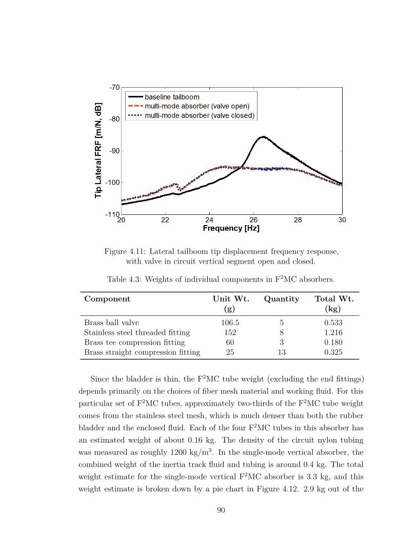
Figure 4.11: Lateral tailboom tip displacement frequency response,with valve in circuit vertical segment open and closed.
Table 4.3: Weights of individual components in F2MC absorbers.
Component Unit Wt.(g)
Quantity Total Wt.(kg)
Brass ball valve 106.5 5 0.533Stainless steel threaded fitting 152 8 1.216Brass tee compression fitting 60 3 0.180Brass straight compression fitting 25 13 0.325
Since the bladder is thin, the F2MC tube weight (excluding the end fittings)depends primarily on the choices of fiber mesh material and working fluid. For thisparticular set of F2MC tubes, approximately two-thirds of the F2MC tube weightcomes from the stainless steel mesh, which is much denser than both the rubberbladder and the enclosed fluid. Each of the four F2MC tubes in this absorber hasan estimated weight of about 0.16 kg. The density of the circuit nylon tubingwas measured as roughly 1200 kg/m3. In the single-mode vertical absorber, thecombined weight of the inertia track fluid and tubing is around 0.4 kg. The totalweight estimate for the single-mode vertical F2MC absorber is 3.3 kg, and thisweight estimate is broken down by a pie chart in Figure 4.12. 2.9 kg out of the
90
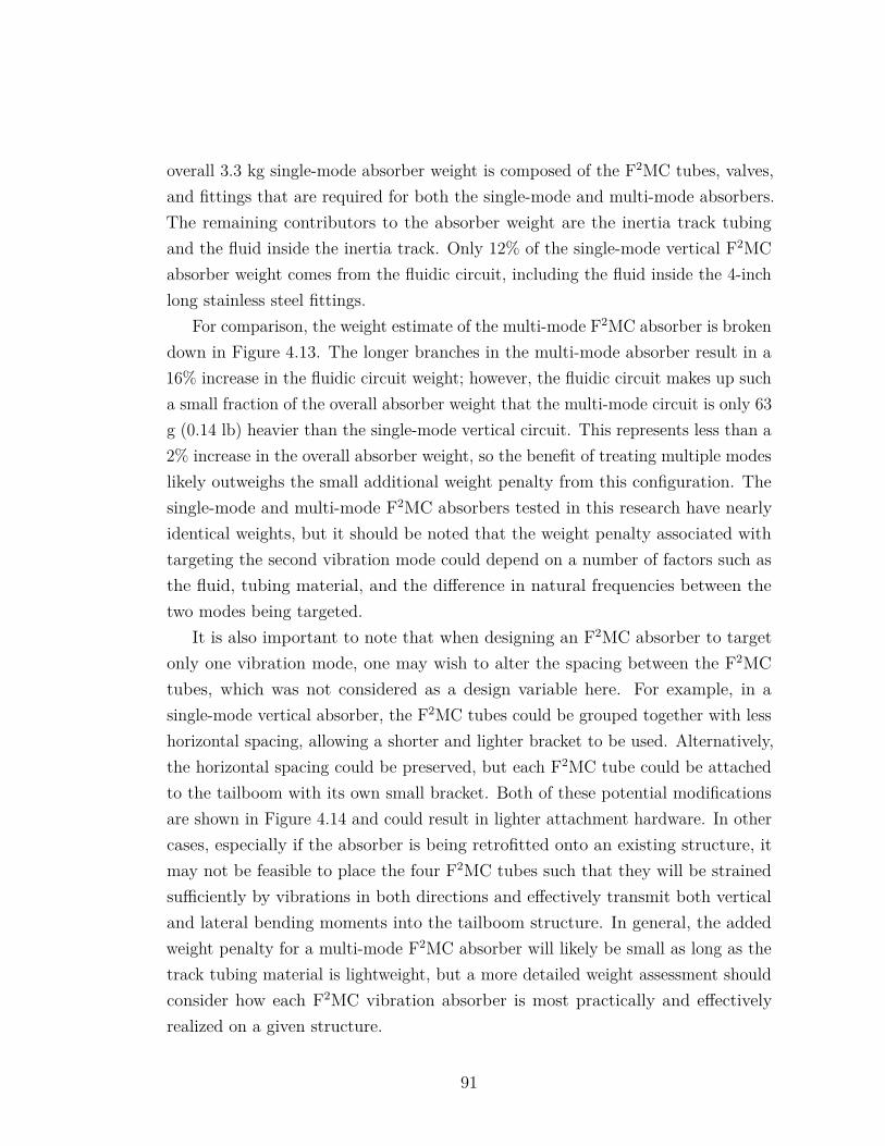
overall 3.3 kg single-mode absorber weight is composed of the F2MC tubes, valves,and fittings that are required for both the single-mode and multi-mode absorbers.The remaining contributors to the absorber weight are the inertia track tubingand the fluid inside the inertia track. Only 12% of the single-mode vertical F2MCabsorber weight comes from the fluidic circuit, including the fluid inside the 4-inchlong stainless steel fittings.
For comparison, the weight estimate of the multi-mode F2MC absorber is brokendown in Figure 4.13. The longer branches in the multi-mode absorber result in a16% increase in the fluidic circuit weight; however, the fluidic circuit makes up sucha small fraction of the overall absorber weight that the multi-mode circuit is only 63g (0.14 lb) heavier than the single-mode vertical circuit. This represents less than a2% increase in the overall absorber weight, so the benefit of treating multiple modeslikely outweighs the small additional weight penalty from this configuration. Thesingle-mode and multi-mode F2MC absorbers tested in this research have nearlyidentical weights, but it should be noted that the weight penalty associated withtargeting the second vibration mode could depend on a number of factors such asthe fluid, tubing material, and the difference in natural frequencies between thetwo modes being targeted.
It is also important to note that when designing an F2MC absorber to targetonly one vibration mode, one may wish to alter the spacing between the F2MCtubes, which was not considered as a design variable here. For example, in asingle-mode vertical absorber, the F2MC tubes could be grouped together with lesshorizontal spacing, allowing a shorter and lighter bracket to be used. Alternatively,the horizontal spacing could be preserved, but each F2MC tube could be attachedto the tailboom with its own small bracket. Both of these potential modificationsare shown in Figure 4.14 and could result in lighter attachment hardware. In othercases, especially if the absorber is being retrofitted onto an existing structure, itmay not be feasible to place the four F2MC tubes such that they will be strainedsufficiently by vibrations in both directions and effectively transmit both verticaland lateral bending moments into the tailboom structure. In general, the addedweight penalty for a multi-mode F2MC absorber will likely be small as long as thetrack tubing material is lightweight, but a more detailed weight assessment shouldconsider how each F2MC vibration absorber is most practically and effectivelyrealized on a given structure.
91
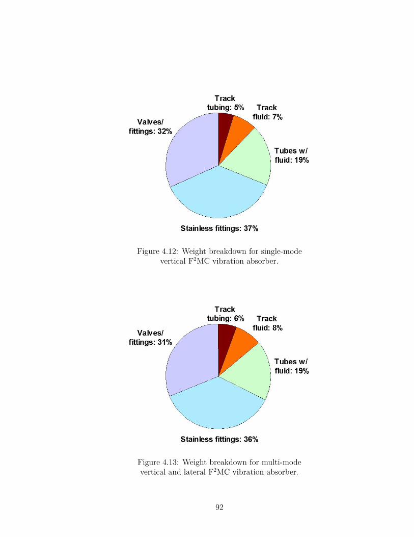
Figure 4.12: Weight breakdown for single-modevertical F2MC vibration absorber.
Figure 4.13: Weight breakdown for multi-modevertical and lateral F2MC vibration absorber.
92
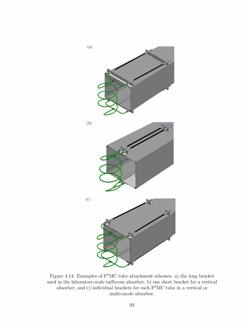
(a)
(b)
(c)
Figure 4.14: Examples of F2MC tube attachment schemes: a) the long bracketused in the laboratory-scale tailboom absorber, b) one short bracket for a vertical
absorber, and c) individual brackets for each F2MC tube in a vertical ormulti-mode absorber.
93
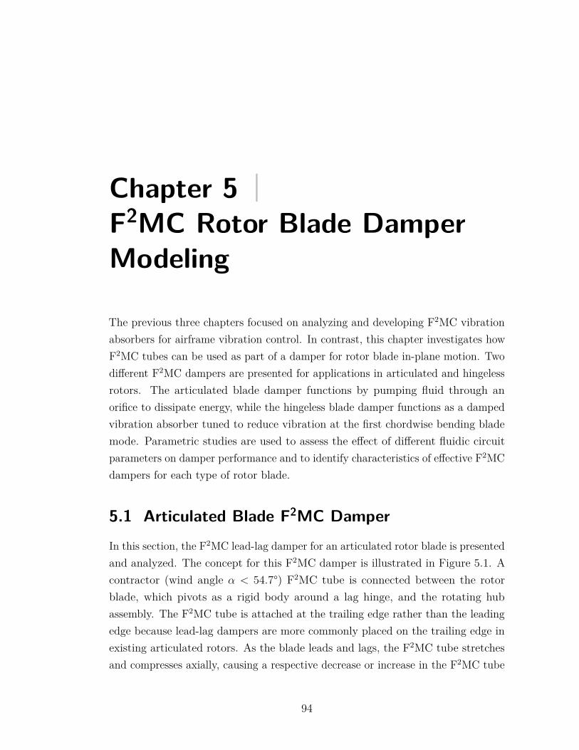
Chapter 5 |F2MC Rotor Blade DamperModeling
The previous three chapters focused on analyzing and developing F2MC vibrationabsorbers for airframe vibration control. In contrast, this chapter investigates howF2MC tubes can be used as part of a damper for rotor blade in-plane motion. Twodifferent F2MC dampers are presented for applications in articulated and hingelessrotors. The articulated blade damper functions by pumping fluid through anorifice to dissipate energy, while the hingeless blade damper functions as a dampedvibration absorber tuned to reduce vibration at the first chordwise bending blademode. Parametric studies are used to assess the effect of different fluidic circuitparameters on damper performance and to identify characteristics of effective F2MCdampers for each type of rotor blade.
5.1 Articulated Blade F2MC DamperIn this section, the F2MC lead-lag damper for an articulated rotor blade is presentedand analyzed. The concept for this F2MC damper is illustrated in Figure 5.1. Acontractor (wind angle α < 54.7°) F2MC tube is connected between the rotorblade, which pivots as a rigid body around a lag hinge, and the rotating hubassembly. The F2MC tube is attached at the trailing edge rather than the leadingedge because lead-lag dampers are more commonly placed on the trailing edge inexisting articulated rotors. As the blade leads and lags, the F2MC tube stretchesand compresses axially, causing a respective decrease or increase in the F2MC tube
94
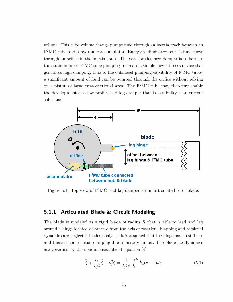
volume. This tube volume change pumps fluid through an inertia track between anF2MC tube and a hydraulic accumulator. Energy is dissipated as this fluid flowsthrough an orifice in the inertia track. The goal for this new damper is to harnessthe strain-induced F2MC tube pumping to create a simple, low-stiffness device thatgenerates high damping. Due to the enhanced pumping capability of F2MC tubes,a significant amount of fluid can be pumped through the orifice without relyingon a piston of large cross-sectional area. The F2MC tube may therefore enablethe development of a low-profile lead-lag damper that is less bulky than currentsolutions.
Figure 5.1: Top view of F2MC lead-lag damper for an articulated rotor blade.
5.1.1 Articulated Blade & Circuit Modeling
The blade is modeled as a rigid blade of radius R that is able to lead and lagaround a hinge located distance e from the axis of rotation. Flapping and torsionaldynamics are neglected in this analysis. It is assumed that the hinge has no stiffnessand there is some initial damping due to aerodynamics. The blade lag dynamicsare governed by the nondimensionalized equation [4]
∗∗ζ + cζ
IζΩ∗ζ + ν2
ζ ζ = 1IζΩ2
∫ R
eFx(r − e)dr. (5.1)
95
where∗
( ) denotes a nondimensional derivative with respect to rotor azimuth angleψ ( d
dψ= 1
Ωddt), ζ denotes blade lag angle, Iζ is the blade mass moment of inertia
about the lag hinge, νζ is the blade lag frequency nondimensionalized by rotor speedΩ, cζ is a linear viscous damping coefficient, and r is the radial coordinate fromthe axis of rotation. The symbol Fx represents the aerodynamic force on the bladeper unit span, excluding aerodynamic damping terms. The initial damping due toaerodynamics and other sources except for the F2MC damper are modeled by theeffective linear viscous damping coefficient so that only one parameter defines thebaseline blade damping.
From [68], the linearized relationship between F2MC tube axial displacement xt(positive for extension), internal tube pressure pt, and axial force Ft acting on thetube is given by
c1xt + c2pt = Ft, (5.2)
and the fluid volume flow rate Q out of the F2MC tube is given by
−c3xt − c4pt = Q. (5.3)
The fluidic circuit for the articulated blade damper is shown in Figure 5.2. Thefluidic circuit is modeled by two equations which express the inertia track andaccumulator dynamics. The inertia track dynamics are governed by the equation
pt − pa = IcQ+RcQ, (5.4)
where pa is the pressure in the accumulator, Ic is the circuit fluid inertance, andRc is the circuit fluid resistance. This fluid resistance Rc captures both losses dueto fluid viscosity as described by Eq. (2.50) and losses due to an orifice in thecircuit. Modeling the pressure difference across an orifice with a linear relationshipbetween pressure and flow rate as in Eq. (5.4) is not a precise model for flowthrough an orifice; however, using this simple equation keeps the overall systemdynamics linear. This is convenient because linear system tools such as frequencyresponse and eigenvalue analysis can be applied to assess the F2MC articulatedblade damper performance.
96
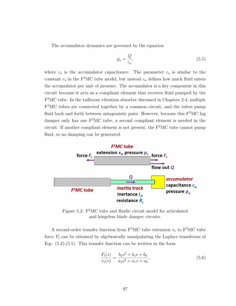
The accumulator dynamics are governed by the equation
pa = Q
ca, (5.5)
where ca is the accumulator capacitance. The parameter ca is similar to theconstant c4 in the F2MC tube model, but instead ca defines how much fluid entersthe accumulator per unit of pressure. The accumulator is a key component in thiscircuit because it acts as a compliant element that receives fluid pumped by theF2MC tube. In the tailboom vibration absorber discussed in Chapters 2-4, multipleF2MC tubes are connected together by a common circuit, and the tubes pumpfluid back and forth between antagonistic pairs. However, because this F2MC lagdamper only has one F2MC tube, a second compliant element is needed in thecircuit. If another compliant element is not present, the F2MC tube cannot pumpfluid, so no damping can be generated.
Figure 5.2: F2MC tube and fluidic circuit model for articulatedand hingeless blade damper circuits.
A second-order transfer function from F2MC tube extension xt to F2MC tubeforce Ft can be obtained by algebraically manipulating the Laplace transforms ofEqs. (5.2)-(5.5). This transfer function can be written in the form
Ft(s)xt(s)
= b2s2 + b1s+ b0
a2s2 + a1s+ a0, (5.6)
97
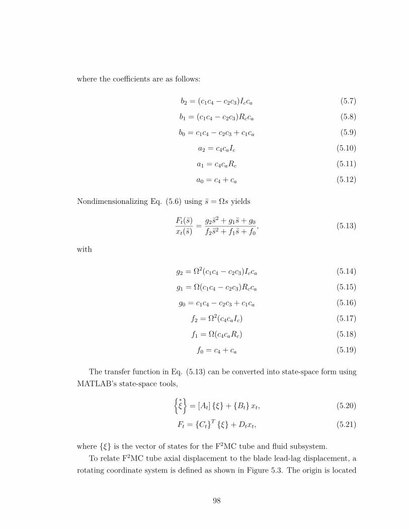
where the coefficients are as follows:
b2 = (c1c4 − c2c3)Icca (5.7)
b1 = (c1c4 − c2c3)Rcca (5.8)
b0 = c1c4 − c2c3 + c1ca (5.9)
a2 = c4caIc (5.10)
a1 = c4caRc (5.11)
a0 = c4 + ca (5.12)
Nondimensionalizing Eq. (5.6) using s = Ωs yields
Ft(s)xt(s)
= g2s2 + g1s+ g0
f2s2 + f1s+ f0, (5.13)
with
g2 = Ω2(c1c4 − c2c3)Icca (5.14)
g1 = Ω(c1c4 − c2c3)Rcca (5.15)
g0 = c1c4 − c2c3 + c1ca (5.16)
f2 = Ω2(c4caIc) (5.17)
f1 = Ω(c4caRc) (5.18)
f0 = c4 + ca (5.19)
The transfer function in Eq. (5.13) can be converted into state-space form usingMATLAB’s state-space tools,∗
ξ
= [At] ξ+ Btxt, (5.20)
Ft = CtT ξ+Dtxt, (5.21)
where ξ is the vector of states for the F2MC tube and fluid subsystem.To relate F2MC tube axial displacement to the blade lead-lag displacement, a
rotating coordinate system is defined as shown in Figure 5.3. The origin is located
98
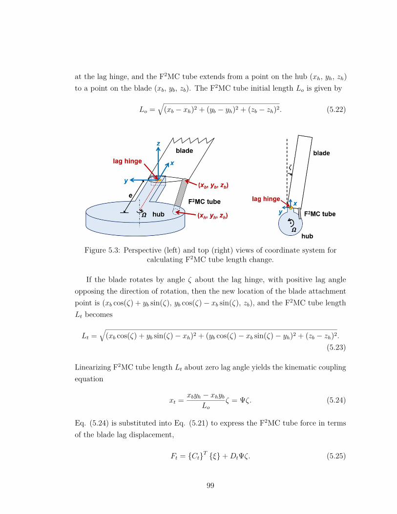
at the lag hinge, and the F2MC tube extends from a point on the hub (xh, yh, zh)to a point on the blade (xb, yb, zb). The F2MC tube initial length Lo is given by
Lo =√
(xb − xh)2 + (yb − yh)2 + (zb − zh)2. (5.22)
Figure 5.3: Perspective (left) and top (right) views of coordinate system forcalculating F2MC tube length change.
If the blade rotates by angle ζ about the lag hinge, with positive lag angleopposing the direction of rotation, then the new location of the blade attachmentpoint is (xb cos(ζ) + yb sin(ζ), yb cos(ζ)− xb sin(ζ), zb), and the F2MC tube lengthLt becomes
Lt =√
(xb cos(ζ) + yb sin(ζ)− xh)2 + (yb cos(ζ)− xb sin(ζ)− yh)2 + (zb − zh)2.
(5.23)
Linearizing F2MC tube length Lt about zero lag angle yields the kinematic couplingequation
xt = xbyh − xhybLo
ζ = Ψζ. (5.24)
Eq. (5.24) is substituted into Eq. (5.21) to express the F2MC tube force in termsof the blade lag displacement,
Ft = CtT ξ+DtΨζ. (5.25)
99
The F2MC tube moment Mt generated about the lag hinge is
Mt = σ(CtT ξ+DtΨζ
), (5.26)
where σ = −Ψ.After nondimensionalizing the F2MC damper moment Mt by dividing by IζΩ2,
inserting it into Eq. (5.1), and expressing all external forcing as an equivalentnondimensional moment Mnd about the lag hinge, the equation of motion for thearticulated rotor blade with F2MC damper becomes
∗∗ζ + cζ
IζΩ∗ζ + ν2
ζ ζ = σ
IζΩ2
(CtT ξ+DtΨζ
)+Mnd. (5.27)
As in Chapter 2, the blade and fluid dynamic equations can be converted tostate-space form,
∗ζ∗∗ζ
∗ξ
=[Asys
]ζ∗ζ
ξ
+
010
Mnd, (5.28)
where
[Asys
]=
0 1 0T
−ν2ζ + σDtΨ
IζΩ2 − cζIζΩ
σCtTIζΩ2
BtΨ 0 [At]
. (5.29)
5.1.2 Case Study: Representative Articulated Blade
A representative articulated blade based on the UH-60 rotor is modeled, and acorresponding F2MC damper is integrated into the blade to analyze its ability todamp the lag mode. The properties of the articulated blade are listed in Table 5.1.For simplicity, the rotor is assumed to have uniform properties along its length, andthe F2MC tube initial position is parallel with the x-axis. Properties of the F2MCtube used in the damper simulated with this blade are given in Table 5.2. Notethat the F2MC tube active length is shorter than the distance between the twoattachment points to account for the presence of fittings at both ends of the tube.
100
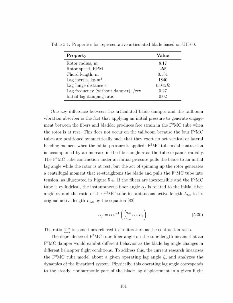
Table 5.1: Properties for representative articulated blade based on UH-60.
Property Value
Rotor radius, m 8.17Rotor speed, RPM 258Chord length, m 0.531Lag inertia, kg-m2 1840Lag hinge distance e 0.045RLag frequency (without damper), /rev 0.27Initial lag damping ratio 0.02
One key difference between the articulated blade damper and the tailboomvibration absorber is the fact that applying an initial pressure to generate engage-ment between the fibers and bladder produces free strain in the F2MC tube whenthe rotor is at rest. This does not occur on the tailboom because the four F2MCtubes are positioned symmetrically such that they exert no net vertical or lateralbending moment when the initial pressure is applied. F2MC tube axial contractionis accompanied by an increase in the fiber angle α as the tube expands radially.The F2MC tube contraction under an initial pressure pulls the blade to an initiallag angle while the rotor is at rest, but the act of spinning up the rotor generatesa centrifugal moment that re-straightens the blade and pulls the F2MC tube intotension, as illustrated in Figure 5.4. If the fibers are inextensible and the F2MCtube is cylindrical, the instantaneous fiber angle αf is related to the initial fiberangle αo and the ratio of the F2MC tube instantaneous active length Lt,a to itsoriginal active length Lo,a by the equation [82]
αf = cos−1(Lt,aLo,a
cosαo). (5.30)
The ratio Lt,aLo,a
is sometimes referred to in literature as the contraction ratio.The dependence of F2MC tube fiber angle on the tube length means that an
F2MC damper would exhibit different behavior as the blade lag angle changes indifferent helicopter flight conditions. To address this, the current research linearizesthe F2MC tube model about a given operating lag angle ζo and analyzes thedynamics of the linearized system. Physically, this operating lag angle correspondsto the steady, nonharmonic part of the blade lag displacement in a given flight
101
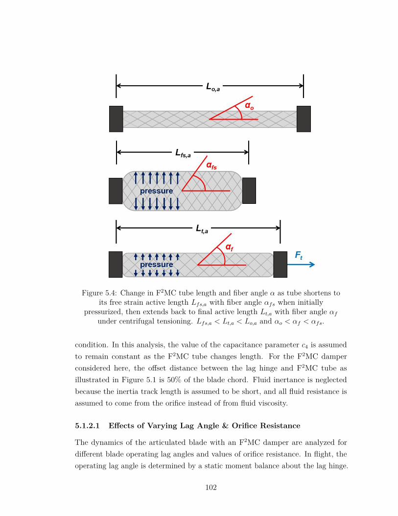
Figure 5.4: Change in F2MC tube length and fiber angle α as tube shortens toits free strain active length Lfs,a with fiber angle αfs when initially
pressurized, then extends back to final active length Lt,a with fiber angle αfunder centrifugal tensioning. Lfs,a < Lt,a < Lo,a and αo < αf < αfs.
condition. In this analysis, the value of the capacitance parameter c4 is assumedto remain constant as the F2MC tube changes length. For the F2MC damperconsidered here, the offset distance between the lag hinge and F2MC tube asillustrated in Figure 5.1 is 50% of the blade chord. Fluid inertance is neglectedbecause the inertia track length is assumed to be short, and all fluid resistance isassumed to come from the orifice instead of from fluid viscosity.
5.1.2.1 Effects of Varying Lag Angle & Orifice Resistance
The dynamics of the articulated blade with an F2MC damper are analyzed fordifferent blade operating lag angles and values of orifice resistance. In flight, theoperating lag angle is determined by a static moment balance about the lag hinge.
102
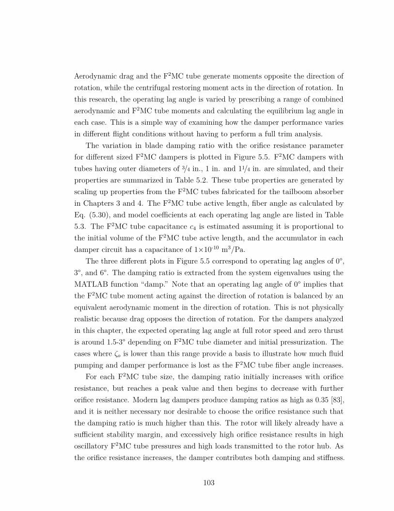
Aerodynamic drag and the F2MC tube generate moments opposite the direction ofrotation, while the centrifugal restoring moment acts in the direction of rotation. Inthis research, the operating lag angle is varied by prescribing a range of combinedaerodynamic and F2MC tube moments and calculating the equilibrium lag angle ineach case. This is a simple way of examining how the damper performance variesin different flight conditions without having to perform a full trim analysis.
The variation in blade damping ratio with the orifice resistance parameterfor different sized F2MC dampers is plotted in Figure 5.5. F2MC dampers withtubes having outer diameters of 3/4 in., 1 in. and 11/4 in. are simulated, and theirproperties are summarized in Table 5.2. These tube properties are generated byscaling up properties from the F2MC tubes fabricated for the tailboom absorberin Chapters 3 and 4. The F2MC tube active length, fiber angle as calculated byEq. (5.30), and model coefficients at each operating lag angle are listed in Table5.3. The F2MC tube capacitance c4 is estimated assuming it is proportional tothe initial volume of the F2MC tube active length, and the accumulator in eachdamper circuit has a capacitance of 1×10⁻¹⁰ m3/Pa.
The three different plots in Figure 5.5 correspond to operating lag angles of 0°,3°, and 6°. The damping ratio is extracted from the system eigenvalues using theMATLAB function “damp.” Note that an operating lag angle of 0° implies thatthe F2MC tube moment acting against the direction of rotation is balanced by anequivalent aerodynamic moment in the direction of rotation. This is not physicallyrealistic because drag opposes the direction of rotation. For the dampers analyzedin this chapter, the expected operating lag angle at full rotor speed and zero thrustis around 1.5-3° depending on F2MC tube diameter and initial pressurization. Thecases where ζo is lower than this range provide a basis to illustrate how much fluidpumping and damper performance is lost as the F2MC tube fiber angle increases.
For each F2MC tube size, the damping ratio initially increases with orificeresistance, but reaches a peak value and then begins to decrease with furtherorifice resistance. Modern lag dampers produce damping ratios as high as 0.35 [83],and it is neither necessary nor desirable to choose the orifice resistance such thatthe damping ratio is much higher than this. The rotor will likely already have asufficient stability margin, and excessively high orifice resistance results in highoscillatory F2MC tube pressures and high loads transmitted to the rotor hub. Asthe orifice resistance increases, the damper contributes both damping and stiffness.
103
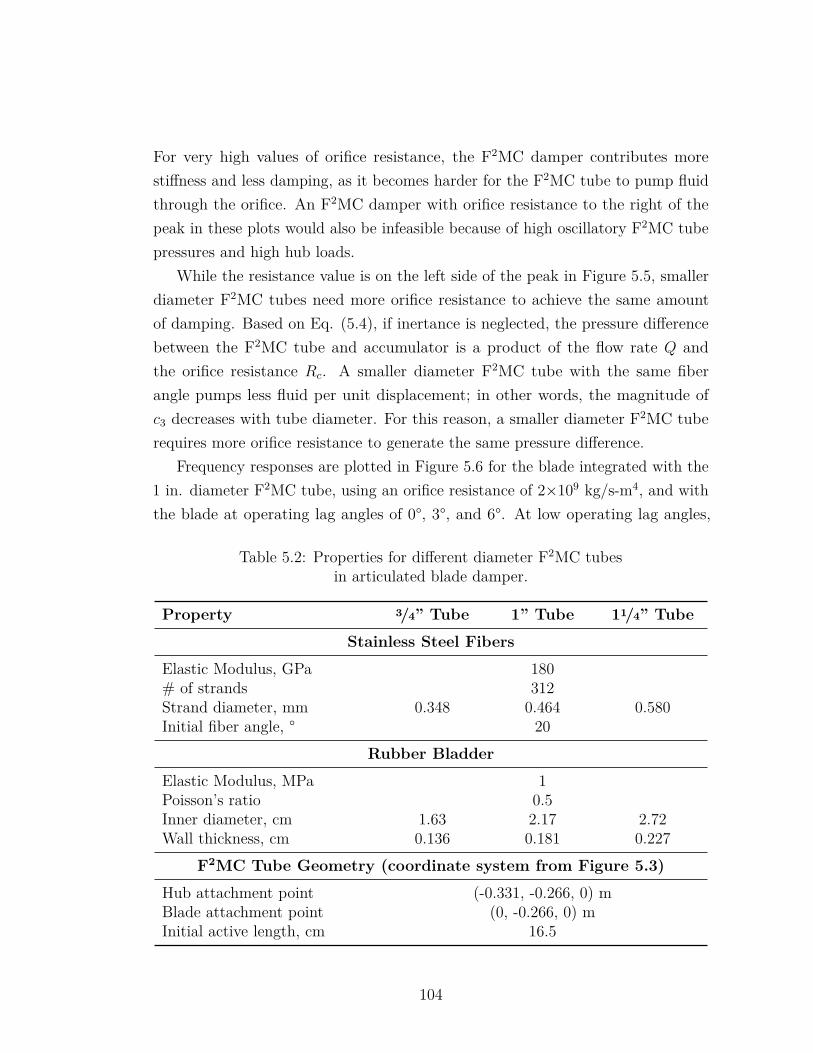
For very high values of orifice resistance, the F2MC damper contributes morestiffness and less damping, as it becomes harder for the F2MC tube to pump fluidthrough the orifice. An F2MC damper with orifice resistance to the right of thepeak in these plots would also be infeasible because of high oscillatory F2MC tubepressures and high hub loads.
While the resistance value is on the left side of the peak in Figure 5.5, smallerdiameter F2MC tubes need more orifice resistance to achieve the same amountof damping. Based on Eq. (5.4), if inertance is neglected, the pressure differencebetween the F2MC tube and accumulator is a product of the flow rate Q andthe orifice resistance Rc. A smaller diameter F2MC tube with the same fiberangle pumps less fluid per unit displacement; in other words, the magnitude ofc3 decreases with tube diameter. For this reason, a smaller diameter F2MC tuberequires more orifice resistance to generate the same pressure difference.
Frequency responses are plotted in Figure 5.6 for the blade integrated with the1 in. diameter F2MC tube, using an orifice resistance of 2×10⁹ kg/s-m4, and withthe blade at operating lag angles of 0°, 3°, and 6°. At low operating lag angles,
Table 5.2: Properties for different diameter F2MC tubesin articulated blade damper.
Property 3/4” Tube 1” Tube 11/4” Tube
Stainless Steel Fibers
Elastic Modulus, GPa 180# of strands 312Strand diameter, mm 0.348 0.464 0.580Initial fiber angle, ° 20
Rubber Bladder
Elastic Modulus, MPa 1Poisson’s ratio 0.5Inner diameter, cm 1.63 2.17 2.72Wall thickness, cm 0.136 0.181 0.227
F2MC Tube Geometry (coordinate system from Figure 5.3)
Hub attachment point (-0.331, -0.266, 0) mBlade attachment point (0, -0.266, 0) mInitial active length, cm 16.5
104
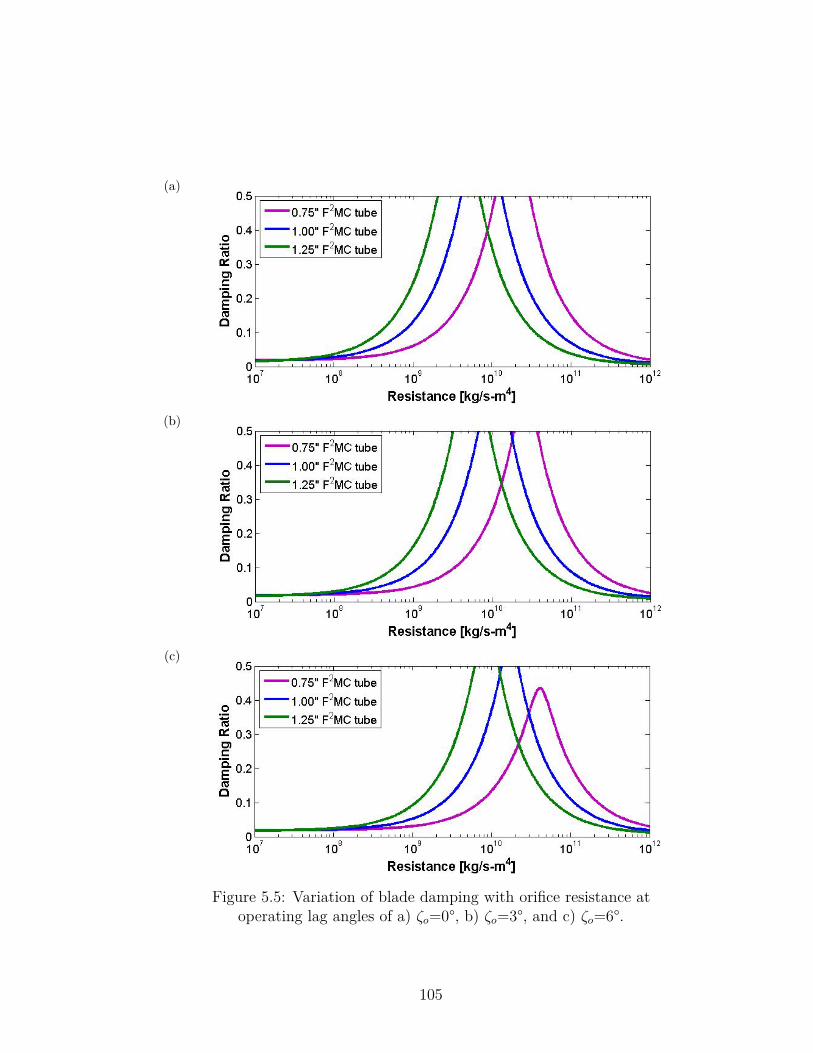
(a)
(b)
(c)
Figure 5.5: Variation of blade damping with orifice resistance atoperating lag angles of a) ζo=0°, b) ζo=3°, and c) ζo=6°.
105
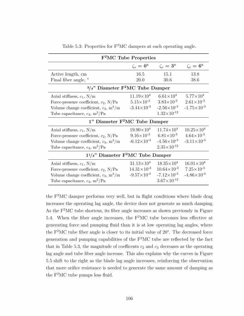
Table 5.3: Properties for F2MC dampers at each operating angle.
F2MC Tube Properties
ζo = 0° ζo = 3° ζo = 6°
Active length, cm 16.5 15.1 13.8Final fiber angle, ° 20.0 30.6 38.6
3/4” Diameter F2MC Tube Damper
Axial stiffness, c1, N/m 11.19×10⁴ 6.61×10⁴ 5.77×10⁴
Force-pressure coefficient, c2, N/Pa 5.15×10⁻³ 3.83×10⁻³ 2.61×10⁻³
Volume change coefficient, c3, m3/m -3.44×10⁻³ -2.56×10⁻³ -1.75×10⁻³
Tube capacitance, c4, m3/Pa 1.32×10⁻¹²
1” Diameter F2MC Tube Damper
Axial stiffness, c1, N/m 19.90×10⁴ 11.74×10⁴ 10.25×10⁴
Force-pressure coefficient, c2, N/Pa 9.16×10⁻³ 6.81×10⁻³ 4.64×10⁻³
Volume change coefficient, c3, m3/m -6.12×10⁻³ -4.56×10⁻³ -3.11×10⁻³
Tube capacitance, c4, m3/Pa 2.35×10⁻¹²
11/4” Diameter F2MC Tube Damper
Axial stiffness, c1, N/m 31.13×10⁴ 18.35×10⁴ 16.01×10⁴
Force-pressure coefficient, c2, N/Pa 14.31×10⁻³ 10.64×10⁻³ 7.25×10⁻³
Volume change coefficient, c3, m3/m -9.57×10⁻³ -7.12×10⁻³ -4.86×10⁻³
Tube capacitance, c4, m3/Pa 3.67×10⁻¹²
the F2MC damper performs very well, but in flight conditions where blade dragincreases the operating lag angle, the device does not generate as much damping.As the F2MC tube shortens, its fiber angle increases as shown previously in Figure5.4. When the fiber angle increases, the F2MC tube becomes less effective atgenerating force and pumping fluid than it is at low operating lag angles, wherethe F2MC tube fiber angle is closer to its initial value of 20°. The decreased forcegeneration and pumping capabilities of the F2MC tube are reflected by the factthat in Table 5.3, the magnitude of coefficents c2 and c3 decreases as the operatinglag angle and tube fiber angle increase. This also explains why the curves in Figure5.5 shift to the right as the blade lag angle increases, reinforcing the observationthat more orifice resistance is needed to generate the same amount of damping asthe F2MC tube pumps less fluid.
106
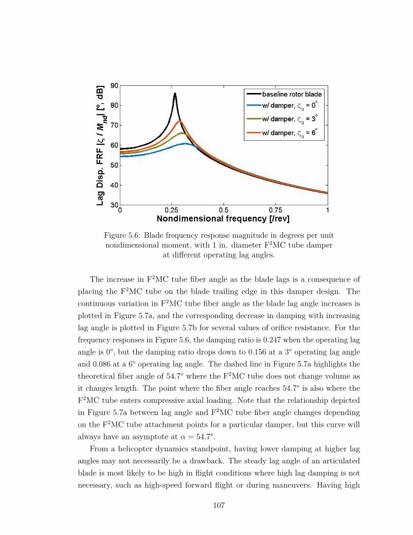
Figure 5.6: Blade frequency response magnitude in degrees per unitnondimensional moment, with 1 in. diameter F2MC tube damper
at different operating lag angles.
The increase in F2MC tube fiber angle as the blade lags is a consequence ofplacing the F2MC tube on the blade trailing edge in this damper design. Thecontinuous variation in F2MC tube fiber angle as the blade lag angle increases isplotted in Figure 5.7a, and the corresponding decrease in damping with increasinglag angle is plotted in Figure 5.7b for several values of orifice resistance. For thefrequency responses in Figure 5.6, the damping ratio is 0.247 when the operating lagangle is 0°, but the damping ratio drops down to 0.156 at a 3° operating lag angleand 0.086 at a 6° operating lag angle. The dashed line in Figure 5.7a highlights thetheoretical fiber angle of 54.7° where the F2MC tube does not change volume asit changes length. The point where the fiber angle reaches 54.7° is also where theF2MC tube enters compressive axial loading. Note that the relationship depictedin Figure 5.7a between lag angle and F2MC tube fiber angle changes dependingon the F2MC tube attachment points for a particular damper, but this curve willalways have an asymptote at α = 54.7°.
From a helicopter dynamics standpoint, having lower damping at higher lagangles may not necessarily be a drawback. The steady lag angle of an articulatedblade is most likely to be high in flight conditions where high lag damping is notnecessary, such as high-speed forward flight or during maneuvers. Having high
107
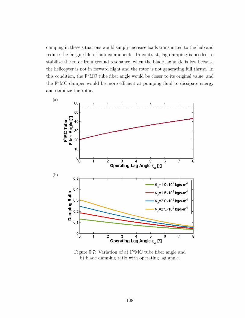
damping in these situations would simply increase loads transmitted to the hub andreduce the fatigue life of hub components. In contrast, lag damping is needed tostabilize the rotor from ground resonance, when the blade lag angle is low becausethe helicopter is not in forward flight and the rotor is not generating full thrust. Inthis condition, the F2MC tube fiber angle would be closer to its original value, andthe F2MC damper would be more efficient at pumping fluid to dissipate energyand stabilize the rotor.
(a)
(b)
Figure 5.7: Variation of a) F2MC tube fiber angle andb) blade damping ratio with operating lag angle.
108
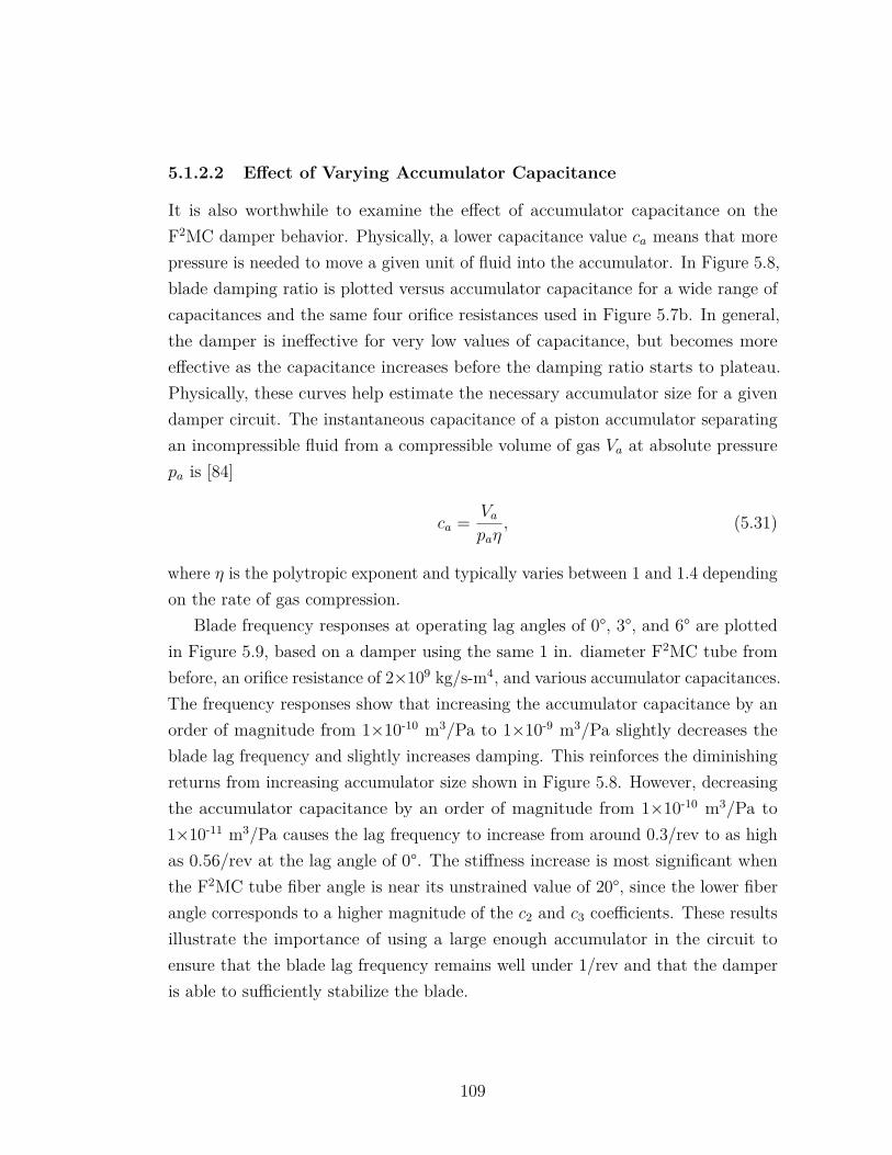
5.1.2.2 Effect of Varying Accumulator Capacitance
It is also worthwhile to examine the effect of accumulator capacitance on theF2MC damper behavior. Physically, a lower capacitance value ca means that morepressure is needed to move a given unit of fluid into the accumulator. In Figure 5.8,blade damping ratio is plotted versus accumulator capacitance for a wide range ofcapacitances and the same four orifice resistances used in Figure 5.7b. In general,the damper is ineffective for very low values of capacitance, but becomes moreeffective as the capacitance increases before the damping ratio starts to plateau.Physically, these curves help estimate the necessary accumulator size for a givendamper circuit. The instantaneous capacitance of a piston accumulator separatingan incompressible fluid from a compressible volume of gas Va at absolute pressurepa is [84]
ca = Vapaη
, (5.31)
where η is the polytropic exponent and typically varies between 1 and 1.4 dependingon the rate of gas compression.
Blade frequency responses at operating lag angles of 0°, 3°, and 6° are plottedin Figure 5.9, based on a damper using the same 1 in. diameter F2MC tube frombefore, an orifice resistance of 2×10⁹ kg/s-m4, and various accumulator capacitances.The frequency responses show that increasing the accumulator capacitance by anorder of magnitude from 1×10⁻¹⁰ m3/Pa to 1×10⁻⁹ m3/Pa slightly decreases theblade lag frequency and slightly increases damping. This reinforces the diminishingreturns from increasing accumulator size shown in Figure 5.8. However, decreasingthe accumulator capacitance by an order of magnitude from 1×10⁻¹⁰ m3/Pa to1×10-11 m3/Pa causes the lag frequency to increase from around 0.3/rev to as highas 0.56/rev at the lag angle of 0°. The stiffness increase is most significant whenthe F2MC tube fiber angle is near its unstrained value of 20°, since the lower fiberangle corresponds to a higher magnitude of the c2 and c3 coefficients. These resultsillustrate the importance of using a large enough accumulator in the circuit toensure that the blade lag frequency remains well under 1/rev and that the damperis able to sufficiently stabilize the blade.
109
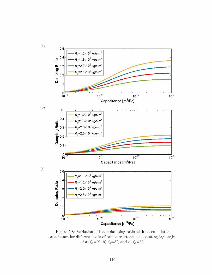
(a)
(b)
(c)
Figure 5.8: Variation of blade damping ratio with acccumulatorcapacitance for different levels of orifice resistance at operating lag angles
of a) ζo=0°, b) ζo=3°, and c) ζo=6°.
110
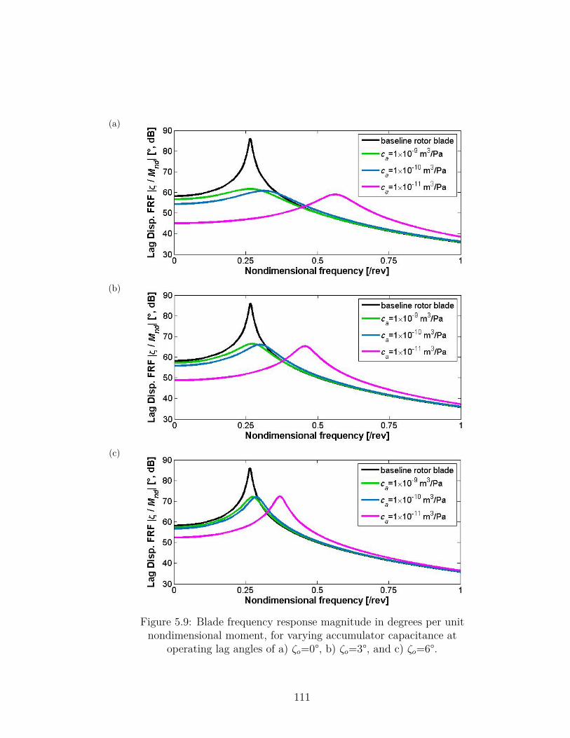
(a)
(b)
(c)
Figure 5.9: Blade frequency response magnitude in degrees per unitnondimensional moment, for varying accumulator capacitance at
operating lag angles of a) ζo=0°, b) ζo=3°, and c) ζo=6°.
111
5.1.2.3 1/rev Steady State Damper Behavior
One practical consideration for any rotor blade damper is that it will be subjectedto cyclic loading at the 1/rev frequency in forward flight. The F2MC tube dampermust therefore be able to withstand the normal 1/rev pressure fluctuations from theharmonic blade lag motion in addition to the pressures that occur as it damps blademotion caused by perturbations or pilot inputs. For the damper to be effective,the F2MC tube should also remain above some minimum pressure that keeps thebladder and fibers engaged. The F2MC tube must be initially pressurized so thatthroughout the flight envelope, its pressure remains above this minimum pressurefor engagement, but below an upper limit determined by the F2MC tube fatiguestrength. This section explains how the F2MC tube pressure fluctuation can beextracted from the linearized system model, and how the magnitude of the 1/revtube pressure varies with the fluidic circuit parameters of orifice resistance andaccumulator capacitance.
The F2MC tube pressure is derived by setting Eqs. (5.2) and (5.25) equal toone another,
Ft = CtT ξ+DtΨζ = c1xt + c2pt. (5.32)
After substituting in xt = Ψζ, this equation can be rearranged to express the F2MCtube pressure as
pt = CtT ξ+ (Dt − c1) Ψζ
c2, (5.33)
The F2MC tube pressure can now be used as an output for the state space modelin Eq. (5.28).
Figures 5.10 and 5.11 plot 1/rev pressure amplitudes versus operating lag anglefor several different values of orifice resistance and accumulator capacitance. Thesepressure amplitudes are normalized per degree of 1/rev lag motion. It is importantto note that the model behind Eq. (5.33) is still linear, and actual 1/rev pressureamplitudes may depend on the amplitude of the cyclic blade motion due to theaforementioned nonlinear F2MC tube behavior. The actual amplitude of the 1/revblade lag motion would vary with flight condition.
112
In Figure 5.10, the accumulator capacitance is held constant at ca=1×10⁻¹⁰
m3/Pa while the orifice resistance is varied. According to Figure 5.7, increasingorifice resistance increases the effectiveness of the F2MC damper, but according toFigure 5.10, this increased damping comes at the cost of higher 1/rev pressuresfor the same F2MC tube. Because the damping force comes directly from theF2MC tube pressure, increasing orifice resistance increases the damper authorityby generating larger tube pressures. However, for the same 1/rev lag motion, theF2MC tube will pump roughly the same amount of fluid, since the fluid pumpingis directly caused by the tube elongation. Based on Eq. (5.4), higher 1/rev tubepressures will be generated if the orifice resistance Rc is increased as Q remainsconstant. These results indicate that there is a trade-off between the amount ofdamping produced by the F2MC damper and the magnitude of 1/rev oscillatorytube pressures that could decrease fatigue life of both the hub and damper.
In Figure 5.11, the orifice resistance is held constant at Rc=2×10⁹ kg/s-m4 whilethe accumulator capacitance is varied. Increasing the accumulator capacitancereduces the 1/rev pressures generated in the F2MC tube, although as in Figure5.8, the benefit diminishes as the accumulator becomes more compliant. Basedon Figures 5.8 and 5.11, increasing accumulator capacitance is shown to make thedamper more effective and decrease 1/rev oscillatory pressures in the F2MC tube.The only drawback to using a larger accumulator is that the damper becomes largerand bulkier, so the benefits of using a larger accumulator must be weighed againstpractical size constraints in a given application.
5.2 Hingeless Blade F2MC DamperUnlike articulated rotor blades, stiff-inplane rotor blades such as those found onadvancing blade concept rotors typically do not have external dampers. Stiff-inplane rotors are not prone to ground resonance; however, they may be prone toother aeroelastic instabilities at high angle of attack or at high advance ratios [85].Currently existing elastomeric and hydraulic dampers are not suitable for stiff-inplane rotor blades, which experience very small deformation at the blade rootas shown in Figure 5.12. On the other hand, devices based on F2MC tubes cansuccessfully reduce structural vibrations even when the F2MC tube elongation isvery small, as demonstrated by the tailboom vibration absorber. The increased
113
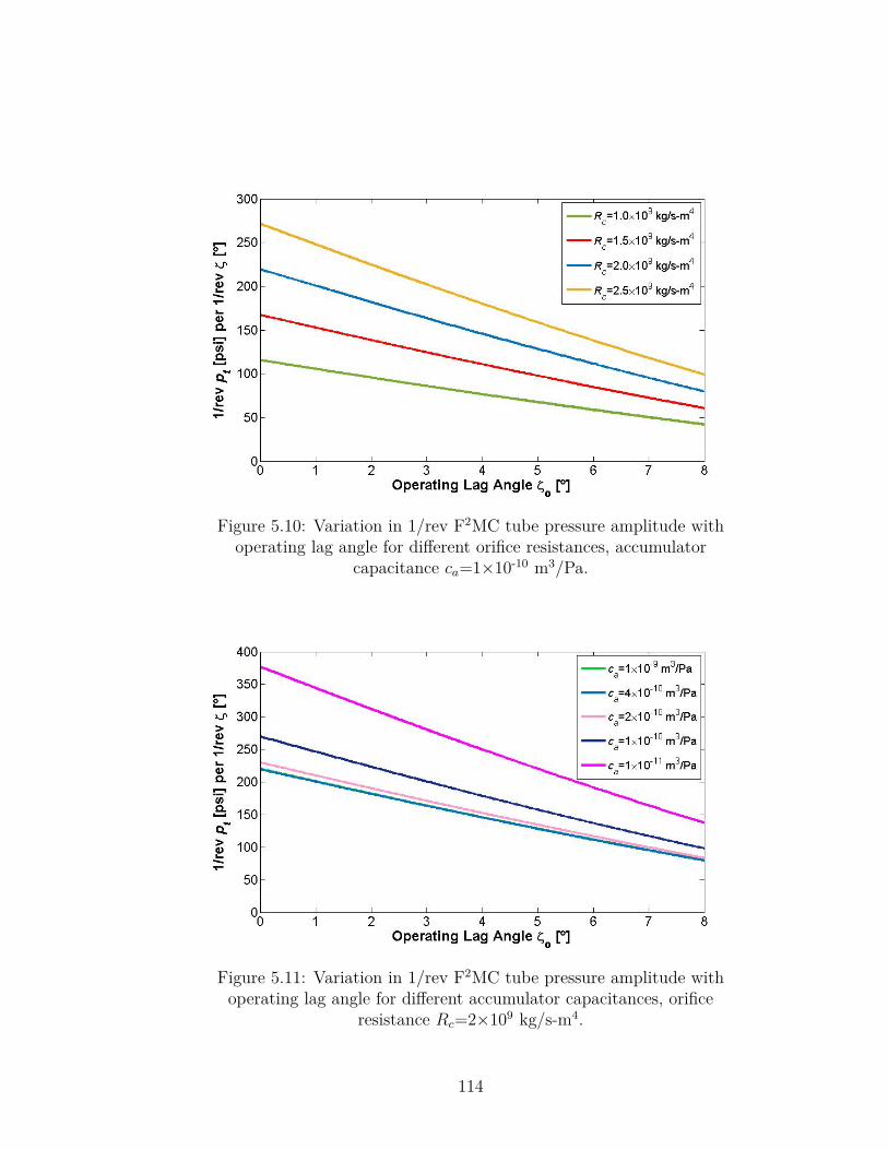
Figure 5.10: Variation in 1/rev F2MC tube pressure amplitude withoperating lag angle for different orifice resistances, accumulator
capacitance ca=1×10⁻¹⁰ m3/Pa.
Figure 5.11: Variation in 1/rev F2MC tube pressure amplitude withoperating lag angle for different accumulator capacitances, orifice
resistance Rc=2×10⁹ kg/s-m4.
114
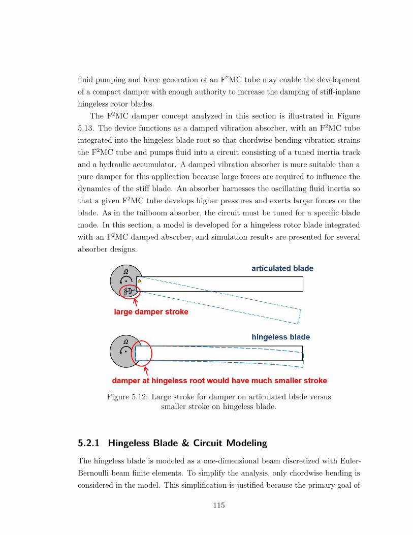
fluid pumping and force generation of an F2MC tube may enable the developmentof a compact damper with enough authority to increase the damping of stiff-inplanehingeless rotor blades.
The F2MC damper concept analyzed in this section is illustrated in Figure5.13. The device functions as a damped vibration absorber, with an F2MC tubeintegrated into the hingeless blade root so that chordwise bending vibration strainsthe F2MC tube and pumps fluid into a circuit consisting of a tuned inertia trackand a hydraulic accumulator. A damped vibration absorber is more suitable than apure damper for this application because large forces are required to influence thedynamics of the stiff blade. An absorber harnesses the oscillating fluid inertia sothat a given F2MC tube develops higher pressures and exerts larger forces on theblade. As in the tailboom absorber, the circuit must be tuned for a specific blademode. In this section, a model is developed for a hingeless rotor blade integratedwith an F2MC damped absorber, and simulation results are presented for severalabsorber designs.
Figure 5.12: Large stroke for damper on articulated blade versussmaller stroke on hingeless blade.
5.2.1 Hingeless Blade & Circuit Modeling
The hingeless blade is modeled as a one-dimensional beam discretized with Euler-Bernoulli beam finite elements. To simplify the analysis, only chordwise bending isconsidered in the model. This simplification is justified because the primary goal of
115
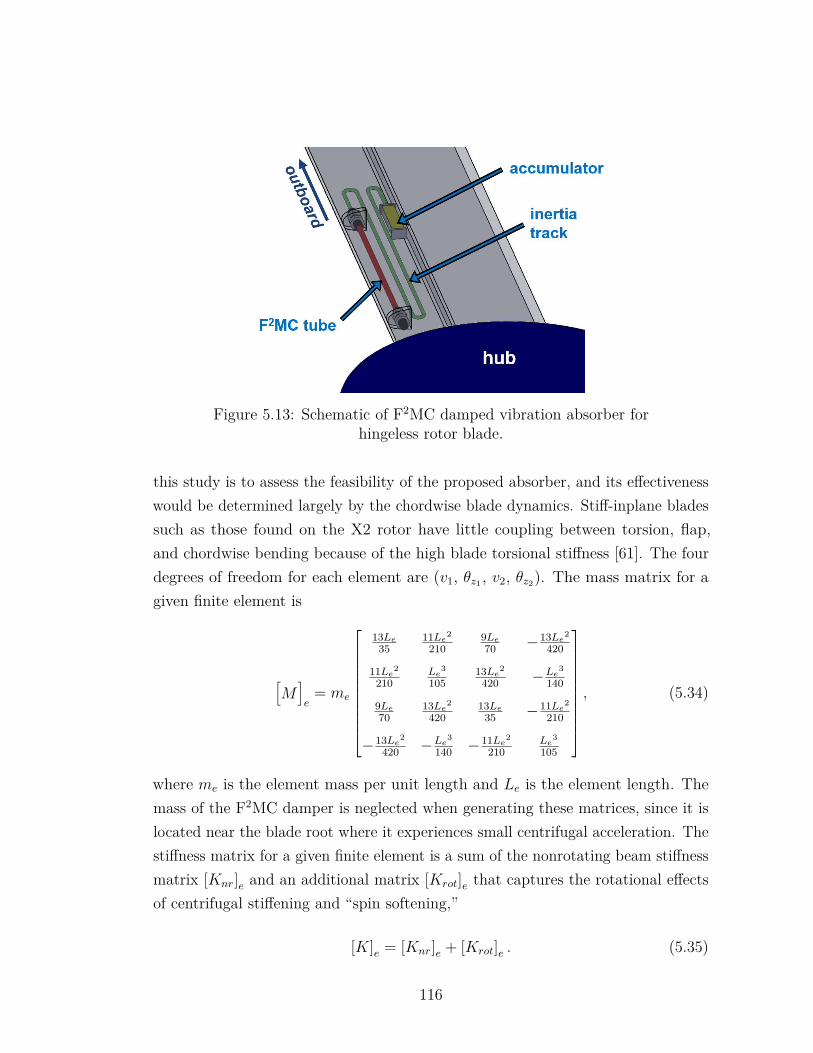
Figure 5.13: Schematic of F2MC damped vibration absorber forhingeless rotor blade.
this study is to assess the feasibility of the proposed absorber, and its effectivenesswould be determined largely by the chordwise blade dynamics. Stiff-inplane bladessuch as those found on the X2 rotor have little coupling between torsion, flap,and chordwise bending because of the high blade torsional stiffness [61]. The fourdegrees of freedom for each element are (v1, θz1 , v2, θz2). The mass matrix for agiven finite element is
[M]e
= me
13Le35
11Le2
2109Le70 −13Le2
420
11Le2
210Le3
10513Le2
420 −Le3
140
9Le70
13Le2
42013Le
35 −11Le2
210
−13Le2
420 −Le3
140 −11Le2
210Le3
105
, (5.34)
where me is the element mass per unit length and Le is the element length. Themass of the F2MC damper is neglected when generating these matrices, since it islocated near the blade root where it experiences small centrifugal acceleration. Thestiffness matrix for a given finite element is a sum of the nonrotating beam stiffnessmatrix [Knr]e and an additional matrix [Krot]e that captures the rotational effectsof centrifugal stiffening and “spin softening,”
[K]e = [Knr]e + [Krot]e . (5.35)
116
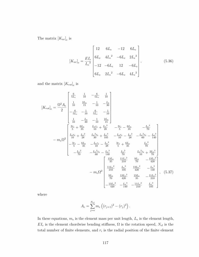
The matrix [Knr]e is
[Knr]e = EIeLe
3
12 6Le −12 6Le
6Le 4Le2 −6Le 2Le2
−12 −6Le 12 −6Le
6Le 2Le2 −6Le 4Le2
, (5.36)
and the matrix [Krot]e is
[Krot]e = Ω2Ae2
65Le
110 − 6
5Le110
110
2Le15 − 1
10 −Le30
− 65Le −
110
65Le − 1
10
110 −Le
30 − 110
2Le15
−meΩ2
3ri5 + 6Le
35Leri10 + Le2
28 −3ri5 −
6Le35 −Le2
70
Leri10 + Le2
28Le2ri
30 + Le3
105 −Leri10 −
Le2
28 −Le2ri60 −
Le3
140
−3ri5 −
6Le35 −Leri
10 −Le2
283ri5 + 6Le
35Le2
70
−Le2
70 −Le2ri60 −
Le3
140Le2
70Le2ri
10 + 3Le3
70
−meΩ2
13Le35
11Le2
2109Le70 −13Le2
420
11Le2
210Le3
10513Le2
420 −Le3
140
9Le70
13Le2
42013Le
35 −11Le2
210
−13Le2
420 −Le3
140 −11Le2
210Le3
105
, (5.37)
where
Ae =Nel∑j=e
me
((rj+1)2 − (rj)2
).
In these equations, me is the element mass per unit length, Le is the element length,EIe is the element chordwise bending stiffness, Ω is the rotation speed, Nel is thetotal number of finite elements, and ri is the radial position of the finite element
117
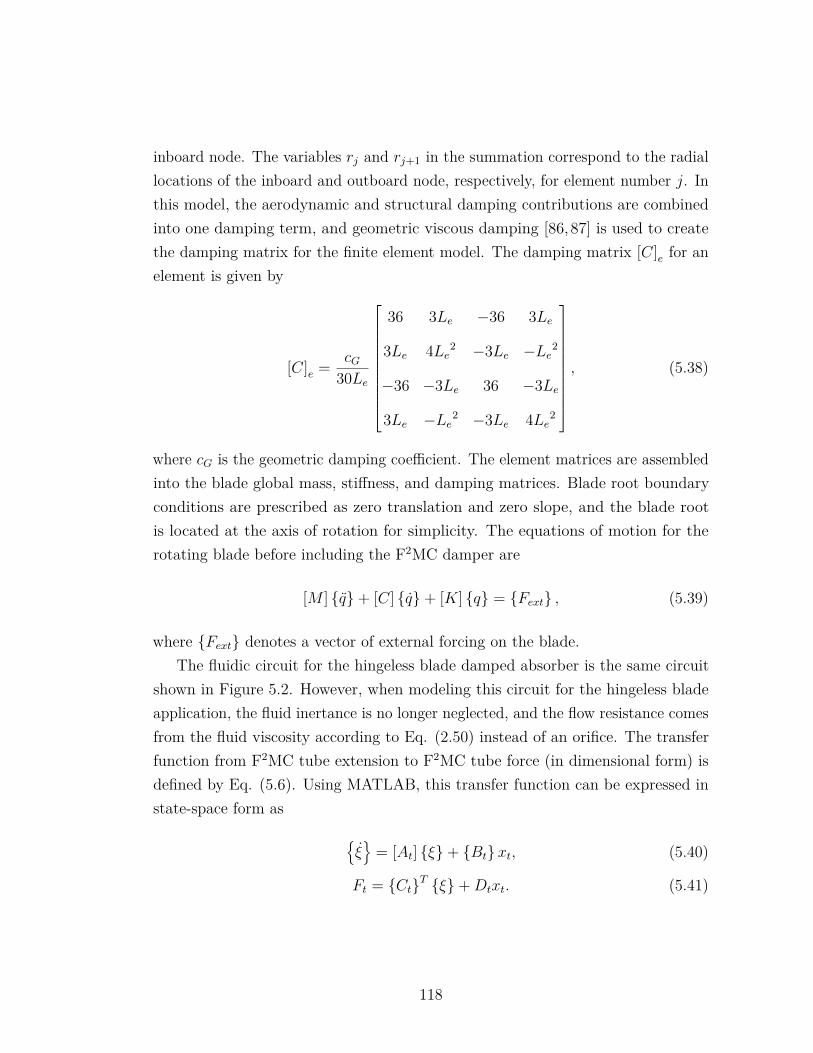
inboard node. The variables rj and rj+1 in the summation correspond to the radiallocations of the inboard and outboard node, respectively, for element number j. Inthis model, the aerodynamic and structural damping contributions are combinedinto one damping term, and geometric viscous damping [86,87] is used to createthe damping matrix for the finite element model. The damping matrix [C]e for anelement is given by
[C]e = cG30Le
36 3Le −36 3Le
3Le 4Le2 −3Le −Le2
−36 −3Le 36 −3Le
3Le −Le2 −3Le 4Le2
, (5.38)
where cG is the geometric damping coefficient. The element matrices are assembledinto the blade global mass, stiffness, and damping matrices. Blade root boundaryconditions are prescribed as zero translation and zero slope, and the blade rootis located at the axis of rotation for simplicity. The equations of motion for therotating blade before including the F2MC damper are
[M ] q+ [C] q+ [K] q = Fext , (5.39)
where Fext denotes a vector of external forcing on the blade.The fluidic circuit for the hingeless blade damped absorber is the same circuit
shown in Figure 5.2. However, when modeling this circuit for the hingeless bladeapplication, the fluid inertance is no longer neglected, and the flow resistance comesfrom the fluid viscosity according to Eq. (2.50) instead of an orifice. The transferfunction from F2MC tube extension to F2MC tube force (in dimensional form) isdefined by Eq. (5.6). Using MATLAB, this transfer function can be expressed instate-space form as
ξ
= [At] ξ+ Btxt, (5.40)
Ft = CtT ξ+Dtxt. (5.41)
118
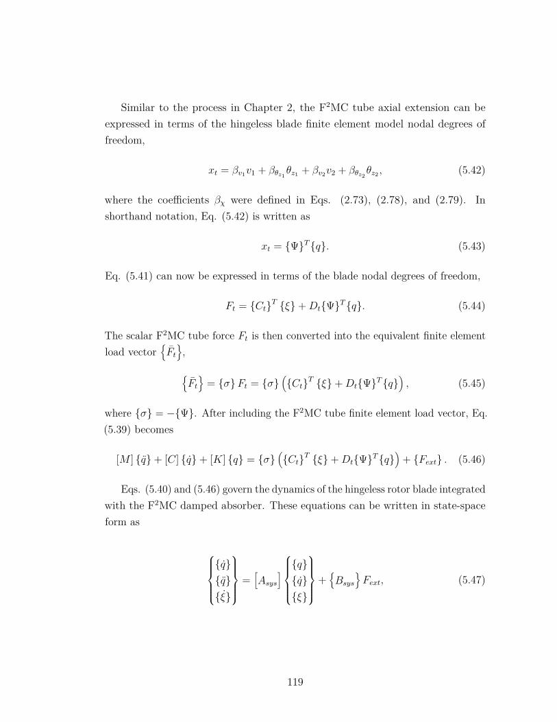
Similar to the process in Chapter 2, the F2MC tube axial extension can beexpressed in terms of the hingeless blade finite element model nodal degrees offreedom,
xt = βv1v1 + βθz1θz1 + βv2v2 + βθz2
θz2 , (5.42)
where the coefficients βχ were defined in Eqs. (2.73), (2.78), and (2.79). Inshorthand notation, Eq. (5.42) is written as
xt = ΨTq. (5.43)
Eq. (5.41) can now be expressed in terms of the blade nodal degrees of freedom,
Ft = CtT ξ+DtΨTq. (5.44)
The scalar F2MC tube force Ft is then converted into the equivalent finite elementload vector
Ft,
Ft
= σFt = σ(CtT ξ+DtΨTq
), (5.45)
where σ = −Ψ. After including the F2MC tube finite element load vector, Eq.(5.39) becomes
[M ] q+ [C] q+ [K] q = σ(CtT ξ+DtΨTq
)+ Fext . (5.46)
Eqs. (5.40) and (5.46) govern the dynamics of the hingeless rotor blade integratedwith the F2MC damped absorber. These equations can be written in state-spaceform as
qqξ
=[Asys
]qqξ
+Bsys
Fext, (5.47)
119
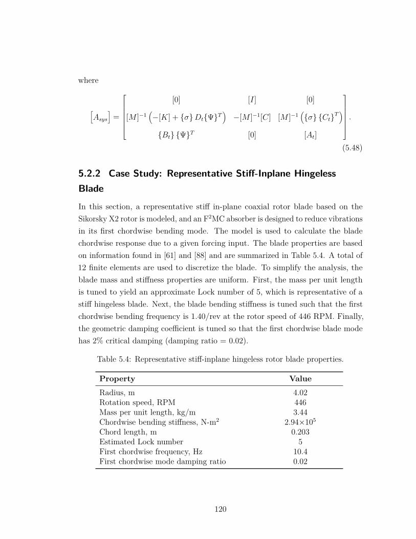
where
[Asys
]=
[0] [I] [0]
[M ]−1(−[K] + σDtΨT
)−[M ]−1[C] [M ]−1
(σ CtT
)Bt ΨT [0] [At]
.(5.48)
5.2.2 Case Study: Representative Stiff-Inplane HingelessBlade
In this section, a representative stiff in-plane coaxial rotor blade based on theSikorsky X2 rotor is modeled, and an F2MC absorber is designed to reduce vibrationsin its first chordwise bending mode. The model is used to calculate the bladechordwise response due to a given forcing input. The blade properties are basedon information found in [61] and [88] and are summarized in Table 5.4. A total of12 finite elements are used to discretize the blade. To simplify the analysis, theblade mass and stiffness properties are uniform. First, the mass per unit lengthis tuned to yield an approximate Lock number of 5, which is representative of astiff hingeless blade. Next, the blade bending stiffness is tuned such that the firstchordwise bending frequency is 1.40/rev at the rotor speed of 446 RPM. Finally,the geometric damping coefficient is tuned so that the first chordwise blade modehas 2% critical damping (damping ratio = 0.02).
Table 5.4: Representative stiff-inplane hingeless rotor blade properties.
Property Value
Radius, m 4.02Rotation speed, RPM 446Mass per unit length, kg/m 3.44Chordwise bending stiffness, N-m2 2.94×10⁵
Chord length, m 0.203Estimated Lock number 5First chordwise frequency, Hz 10.4First chordwise mode damping ratio 0.02
120
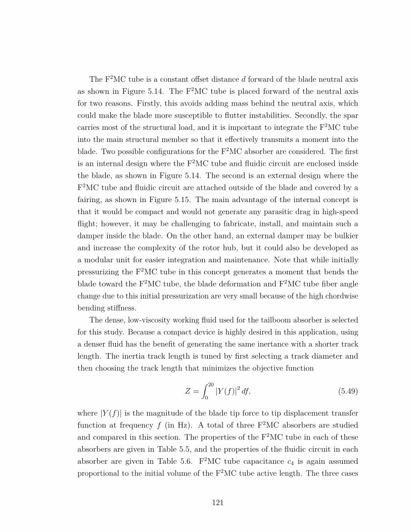
The F2MC tube is a constant offset distance d forward of the blade neutral axisas shown in Figure 5.14. The F2MC tube is placed forward of the neutral axisfor two reasons. Firstly, this avoids adding mass behind the neutral axis, whichcould make the blade more susceptible to flutter instabilities. Secondly, the sparcarries most of the structural load, and it is important to integrate the F2MC tubeinto the main structural member so that it effectively transmits a moment into theblade. Two possible configurations for the F2MC absorber are considered. The firstis an internal design where the F2MC tube and fluidic circuit are enclosed insidethe blade, as shown in Figure 5.14. The second is an external design where theF2MC tube and fluidic circuit are attached outside of the blade and covered by afairing, as shown in Figure 5.15. The main advantage of the internal concept isthat it would be compact and would not generate any parasitic drag in high-speedflight; however, it may be challenging to fabricate, install, and maintain such adamper inside the blade. On the other hand, an external damper may be bulkierand increase the complexity of the rotor hub, but it could also be developed asa modular unit for easier integration and maintenance. Note that while initiallypressurizing the F2MC tube in this concept generates a moment that bends theblade toward the F2MC tube, the blade deformation and F2MC tube fiber anglechange due to this initial pressurization are very small because of the high chordwisebending stiffness.
The dense, low-viscosity working fluid used for the tailboom absorber is selectedfor this study. Because a compact device is highly desired in this application, usinga denser fluid has the benefit of generating the same inertance with a shorter tracklength. The inertia track length is tuned by first selecting a track diameter andthen choosing the track length that minimizes the objective function
Z =∫ 20
0|Y (f)|2 df, (5.49)
where |Y (f)| is the magnitude of the blade tip force to tip displacement transferfunction at frequency f (in Hz). A total of three F2MC absorbers are studiedand compared in this section. The properties of the F2MC tube in each of theseabsorbers are given in Table 5.5, and the properties of the fluidic circuit in eachabsorber are given in Table 5.6. F2MC tube capacitance c4 is again assumedproportional to the initial volume of the F2MC tube active length. The three cases
121
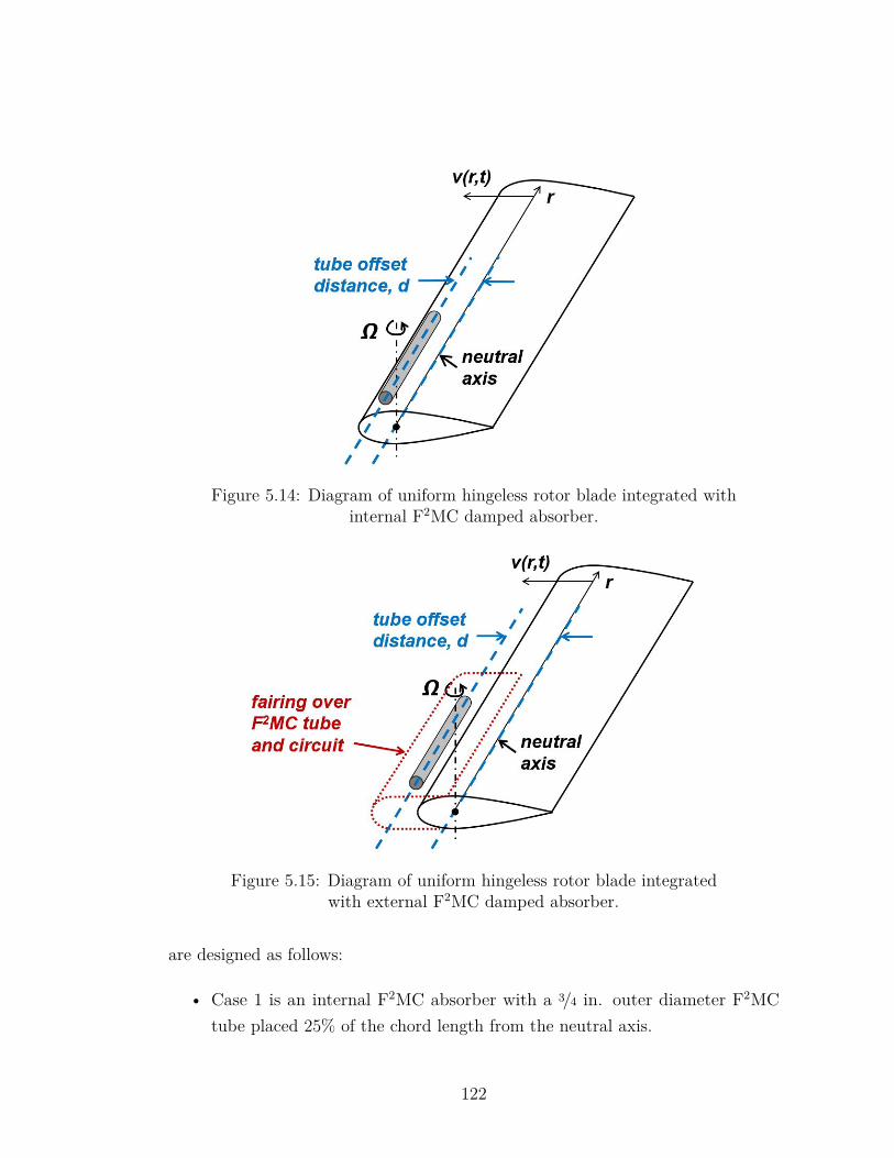
Figure 5.14: Diagram of uniform hingeless rotor blade integrated withinternal F2MC damped absorber.
Figure 5.15: Diagram of uniform hingeless rotor blade integratedwith external F2MC damped absorber.
are designed as follows:
• Case 1 is an internal F2MC absorber with a 3/4 in. outer diameter F2MCtube placed 25% of the chord length from the neutral axis.
122
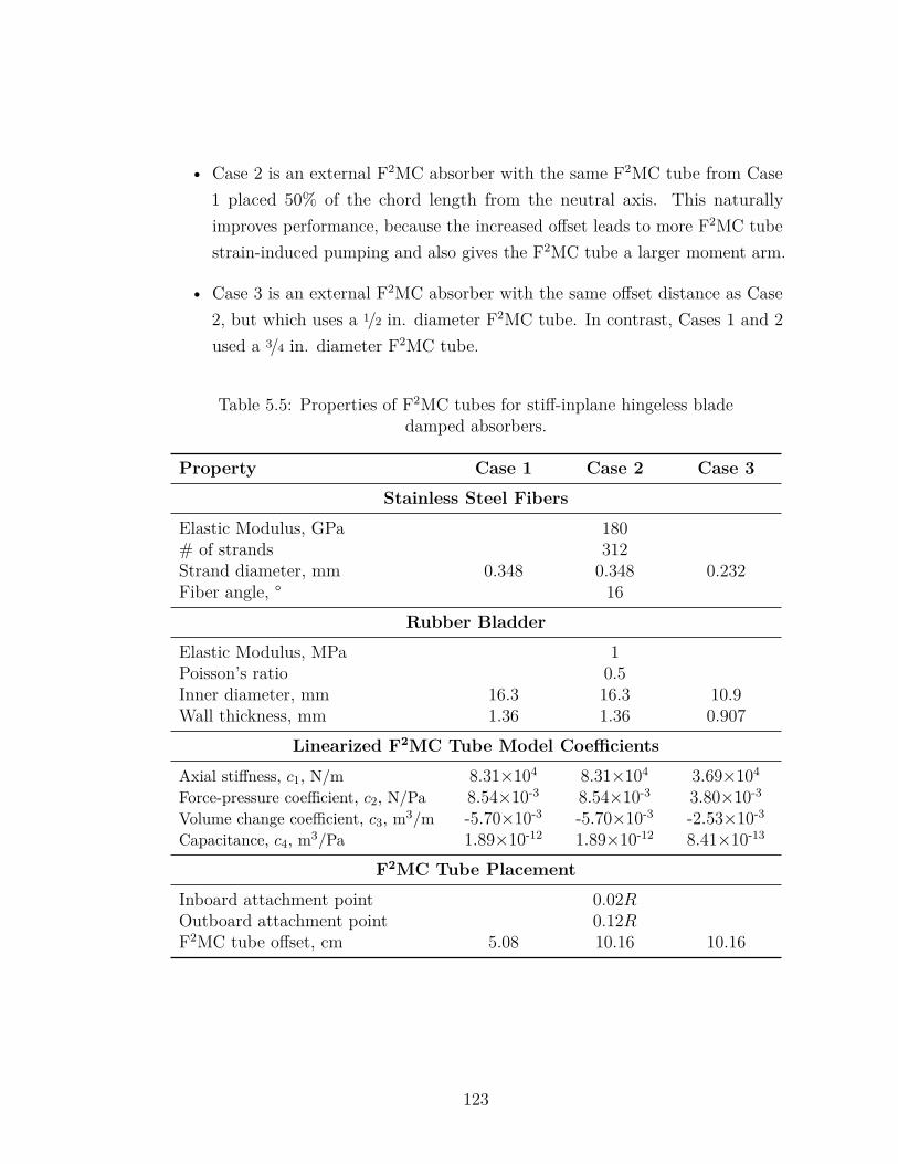
• Case 2 is an external F2MC absorber with the same F2MC tube from Case1 placed 50% of the chord length from the neutral axis. This naturallyimproves performance, because the increased offset leads to more F2MC tubestrain-induced pumping and also gives the F2MC tube a larger moment arm.
• Case 3 is an external F2MC absorber with the same offset distance as Case2, but which uses a 1/2 in. diameter F2MC tube. In contrast, Cases 1 and 2used a 3/4 in. diameter F2MC tube.
Table 5.5: Properties of F2MC tubes for stiff-inplane hingeless bladedamped absorbers.
Property Case 1 Case 2 Case 3
Stainless Steel Fibers
Elastic Modulus, GPa 180# of strands 312Strand diameter, mm 0.348 0.348 0.232Fiber angle, ° 16
Rubber Bladder
Elastic Modulus, MPa 1Poisson’s ratio 0.5Inner diameter, mm 16.3 16.3 10.9Wall thickness, mm 1.36 1.36 0.907
Linearized F2MC Tube Model Coefficients
Axial stiffness, c1, N/m 8.31×10⁴ 8.31×10⁴ 3.69×10⁴
Force-pressure coefficient, c2, N/Pa 8.54×10⁻³ 8.54×10⁻³ 3.80×10⁻³
Volume change coefficient, c3, m3/m -5.70×10⁻³ -5.70×10⁻³ -2.53×10⁻³
Capacitance, c4, m3/Pa 1.89×10⁻¹² 1.89×10⁻¹² 8.41×10⁻¹³
F2MC Tube Placement
Inboard attachment point 0.02ROutboard attachment point 0.12RF2MC tube offset, cm 5.08 10.16 10.16
123
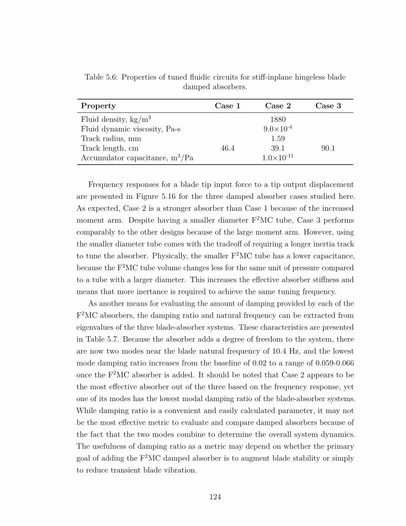
Table 5.6: Properties of tuned fluidic circuits for stiff-inplane hingeless bladedamped absorbers.
Property Case 1 Case 2 Case 3
Fluid density, kg/m3 1880Fluid dynamic viscosity, Pa-s 9.0×10⁻⁴
Track radius, mm 1.59Track length, cm 46.4 39.1 90.1Accumulator capacitance, m3/Pa 1.0×10⁻¹¹
Frequency responses for a blade tip input force to a tip output displacementare presented in Figure 5.16 for the three damped absorber cases studied here.As expected, Case 2 is a stronger absorber than Case 1 because of the increasedmoment arm. Despite having a smaller diameter F2MC tube, Case 3 performscomparably to the other designs because of the large moment arm. However, usingthe smaller diameter tube comes with the tradeoff of requiring a longer inertia trackto tune the absorber. Physically, the smaller F2MC tube has a lower capacitance,because the F2MC tube volume changes less for the same unit of pressure comparedto a tube with a larger diameter. This increases the effective absorber stiffness andmeans that more inertance is required to achieve the same tuning frequency.
As another means for evaluating the amount of damping provided by each of theF2MC absorbers, the damping ratio and natural frequency can be extracted fromeigenvalues of the three blade-absorber systems. These characteristics are presentedin Table 5.7. Because the absorber adds a degree of freedom to the system, thereare now two modes near the blade natural frequency of 10.4 Hz, and the lowestmode damping ratio increases from the baseline of 0.02 to a range of 0.059-0.066once the F2MC absorber is added. It should be noted that Case 2 appears to bethe most effective absorber out of the three based on the frequency response, yetone of its modes has the lowest modal damping ratio of the blade-absorber systems.While damping ratio is a convenient and easily calculated parameter, it may notbe the most effective metric to evaluate and compare damped absorbers because ofthe fact that the two modes combine to determine the overall system dynamics.The usefulness of damping ratio as a metric may depend on whether the primarygoal of adding the F2MC damped absorber is to augment blade stability or simplyto reduce transient blade vibration.
124
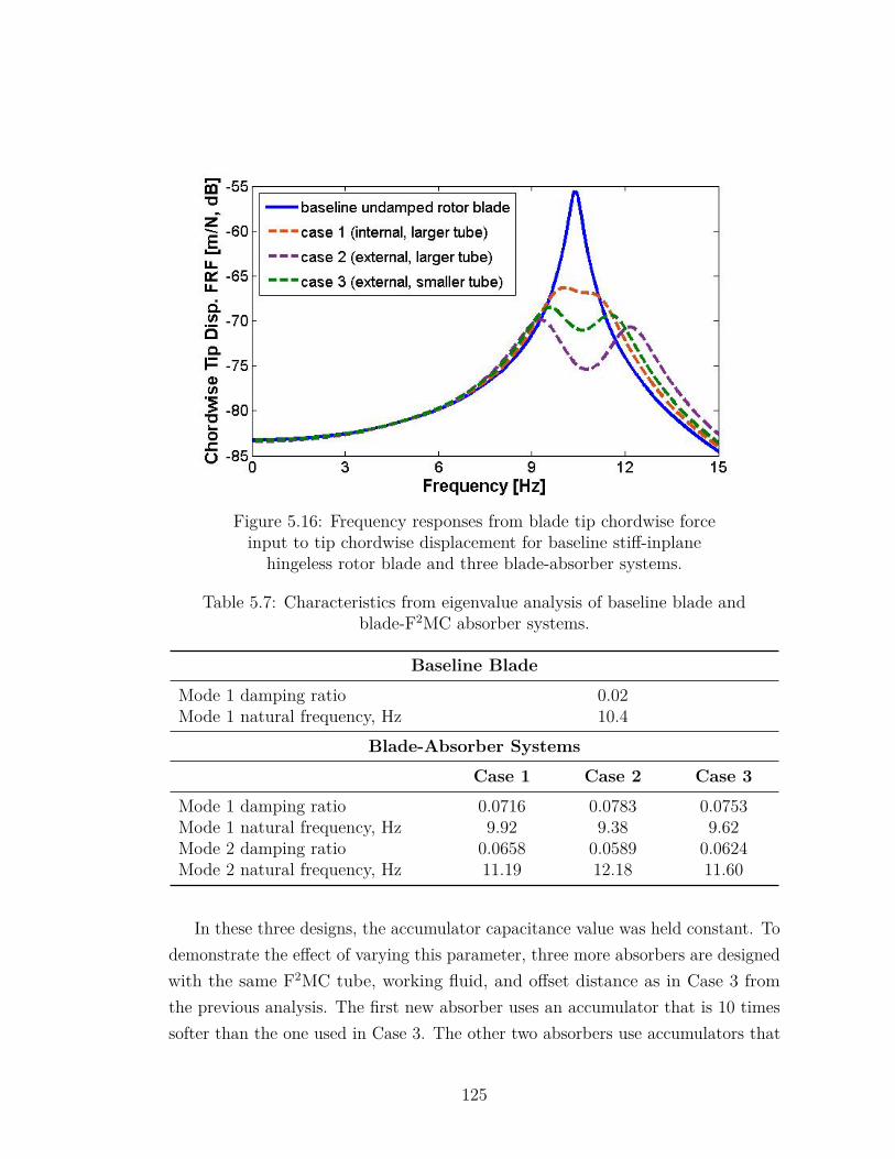
Figure 5.16: Frequency responses from blade tip chordwise forceinput to tip chordwise displacement for baseline stiff-inplane
hingeless rotor blade and three blade-absorber systems.
Table 5.7: Characteristics from eigenvalue analysis of baseline blade andblade-F2MC absorber systems.
Baseline Blade
Mode 1 damping ratio 0.02Mode 1 natural frequency, Hz 10.4
Blade-Absorber Systems
Case 1 Case 2 Case 3
Mode 1 damping ratio 0.0716 0.0783 0.0753Mode 1 natural frequency, Hz 9.92 9.38 9.62Mode 2 damping ratio 0.0658 0.0589 0.0624Mode 2 natural frequency, Hz 11.19 12.18 11.60
In these three designs, the accumulator capacitance value was held constant. Todemonstrate the effect of varying this parameter, three more absorbers are designedwith the same F2MC tube, working fluid, and offset distance as in Case 3 fromthe previous analysis. The first new absorber uses an accumulator that is 10 timessofter than the one used in Case 3. The other two absorbers use accumulators that
125
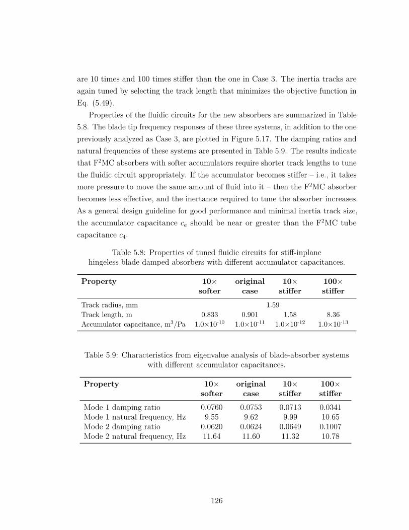
are 10 times and 100 times stiffer than the one in Case 3. The inertia tracks areagain tuned by selecting the track length that minimizes the objective function inEq. (5.49).
Properties of the fluidic circuits for the new absorbers are summarized in Table5.8. The blade tip frequency responses of these three systems, in addition to the onepreviously analyzed as Case 3, are plotted in Figure 5.17. The damping ratios andnatural frequencies of these systems are presented in Table 5.9. The results indicatethat F2MC absorbers with softer accumulators require shorter track lengths to tunethe fluidic circuit appropriately. If the accumulator becomes stiffer – i.e., it takesmore pressure to move the same amount of fluid into it – then the F2MC absorberbecomes less effective, and the inertance required to tune the absorber increases.As a general design guideline for good performance and minimal inertia track size,the accumulator capacitance ca should be near or greater than the F2MC tubecapacitance c4.
Table 5.8: Properties of tuned fluidic circuits for stiff-inplanehingeless blade damped absorbers with different accumulator capacitances.
Property 10×softer
originalcase
10×stiffer
100×stiffer
Track radius, mm 1.59Track length, m 0.833 0.901 1.58 8.36Accumulator capacitance, m3/Pa 1.0×10⁻¹⁰ 1.0×10⁻¹¹ 1.0×10⁻¹² 1.0×10⁻¹³
Table 5.9: Characteristics from eigenvalue analysis of blade-absorber systemswith different accumulator capacitances.
Property 10×softer
originalcase
10×stiffer
100×stiffer
Mode 1 damping ratio 0.0760 0.0753 0.0713 0.0341Mode 1 natural frequency, Hz 9.55 9.62 9.99 10.65Mode 2 damping ratio 0.0620 0.0624 0.0649 0.1007Mode 2 natural frequency, Hz 11.64 11.60 11.32 10.78
126
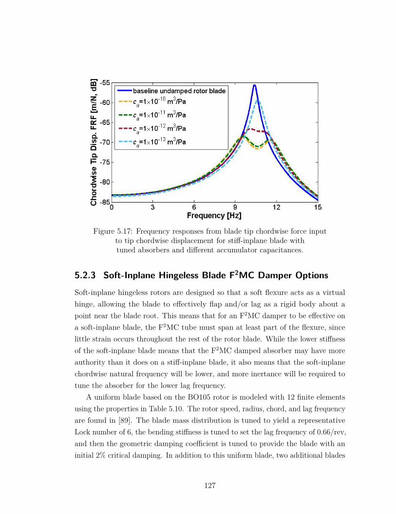
Figure 5.17: Frequency responses from blade tip chordwise force inputto tip chordwise displacement for stiff-inplane blade withtuned absorbers and different accumulator capacitances.
5.2.3 Soft-Inplane Hingeless Blade F2MC Damper Options
Soft-inplane hingeless rotors are designed so that a soft flexure acts as a virtualhinge, allowing the blade to effectively flap and/or lag as a rigid body about apoint near the blade root. This means that for an F2MC damper to be effective ona soft-inplane blade, the F2MC tube must span at least part of the flexure, sincelittle strain occurs throughout the rest of the rotor blade. While the lower stiffnessof the soft-inplane blade means that the F2MC damped absorber may have moreauthority than it does on a stiff-inplane blade, it also means that the soft-inplanechordwise natural frequency will be lower, and more inertance will be required totune the absorber for the lower lag frequency.
A uniform blade based on the BO105 rotor is modeled with 12 finite elementsusing the properties in Table 5.10. The rotor speed, radius, chord, and lag frequencyare found in [89]. The blade mass distribution is tuned to yield a representativeLock number of 6, the bending stiffness is tuned to set the lag frequency of 0.66/rev,and then the geometric damping coefficient is tuned to provide the blade with aninitial 2% critical damping. In addition to this uniform blade, two additional blades
127
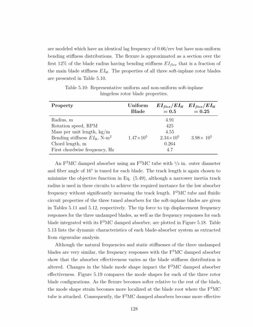
are modeled which have an identical lag frequency of 0.66/rev but have non-uniformbending stiffness distributions. The flexure is approximated as a section over thefirst 12% of the blade radius having bending stiffness EIflex that is a fraction ofthe main blade stiffness EIbl. The properties of all three soft-inplane rotor bladesare presented in Table 5.10.
Table 5.10: Representative uniform and non-uniform soft-inplanehingeless rotor blade properties.
Property UniformBlade
EIflex/EIbl
= 0.5EIflex/EIbl
= 0.25
Radius, m 4.91Rotation speed, RPM 425Mass per unit length, kg/m 4.55Bending stiffness EIbl, N-m2 1.47×10⁵ 2.34×10⁵ 3.98× 10⁵
Chord length, m 0.264First chordwise frequency, Hz 4.7
An F2MC damped absorber using an F2MC tube with 1/2 in. outer diameterand fiber angle of 16° is tuned for each blade. The track length is again chosen tominimize the objective function in Eq. (5.49), although a narrower inertia trackradius is used in these circuits to achieve the required inertance for the low absorberfrequency without significantly increasing the track length. F2MC tube and fluidiccircuit properties of the three tuned absorbers for the soft-inplane blades are givenin Tables 5.11 and 5.12, respectively. The tip force to tip displacement frequencyresponses for the three undamped blades, as well as the frequency responses for eachblade integrated with its F2MC damped absorber, are plotted in Figure 5.18. Table5.13 lists the dynamic characteristics of each blade-absorber system as extractedfrom eigenvalue analysis.
Although the natural frequencies and static stiffnesses of the three undampedblades are very similar, the frequency responses with the F2MC damped absorbershow that the absorber effectiveness varies as the blade stiffness distribution isaltered. Changes in the blade mode shape impact the F2MC damped absorbereffectiveness. Figure 5.19 compares the mode shapes for each of the three rotorblade configurations. As the flexure becomes softer relative to the rest of the blade,the mode shape strain becomes more localized at the blade root where the F2MCtube is attached. Consequently, the F2MC damped absorbers become more effective
128
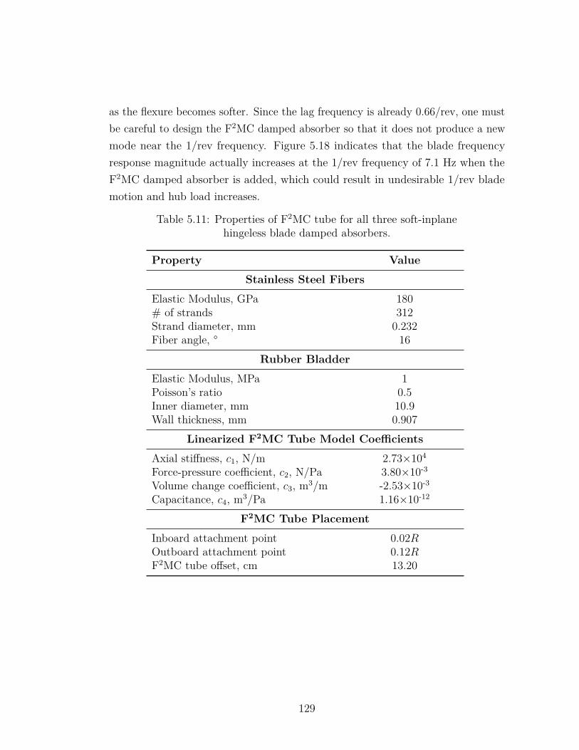
as the flexure becomes softer. Since the lag frequency is already 0.66/rev, one mustbe careful to design the F2MC damped absorber so that it does not produce a newmode near the 1/rev frequency. Figure 5.18 indicates that the blade frequencyresponse magnitude actually increases at the 1/rev frequency of 7.1 Hz when theF2MC damped absorber is added, which could result in undesirable 1/rev blademotion and hub load increases.
Table 5.11: Properties of F2MC tube for all three soft-inplanehingeless blade damped absorbers.
Property Value
Stainless Steel Fibers
Elastic Modulus, GPa 180# of strands 312Strand diameter, mm 0.232Fiber angle, ° 16
Rubber Bladder
Elastic Modulus, MPa 1Poisson’s ratio 0.5Inner diameter, mm 10.9Wall thickness, mm 0.907
Linearized F2MC Tube Model Coefficients
Axial stiffness, c1, N/m 2.73×10⁴
Force-pressure coefficient, c2, N/Pa 3.80×10⁻³
Volume change coefficient, c3, m3/m -2.53×10⁻³
Capacitance, c4, m3/Pa 1.16×10⁻¹²
F2MC Tube Placement
Inboard attachment point 0.02ROutboard attachment point 0.12RF2MC tube offset, cm 13.20
129
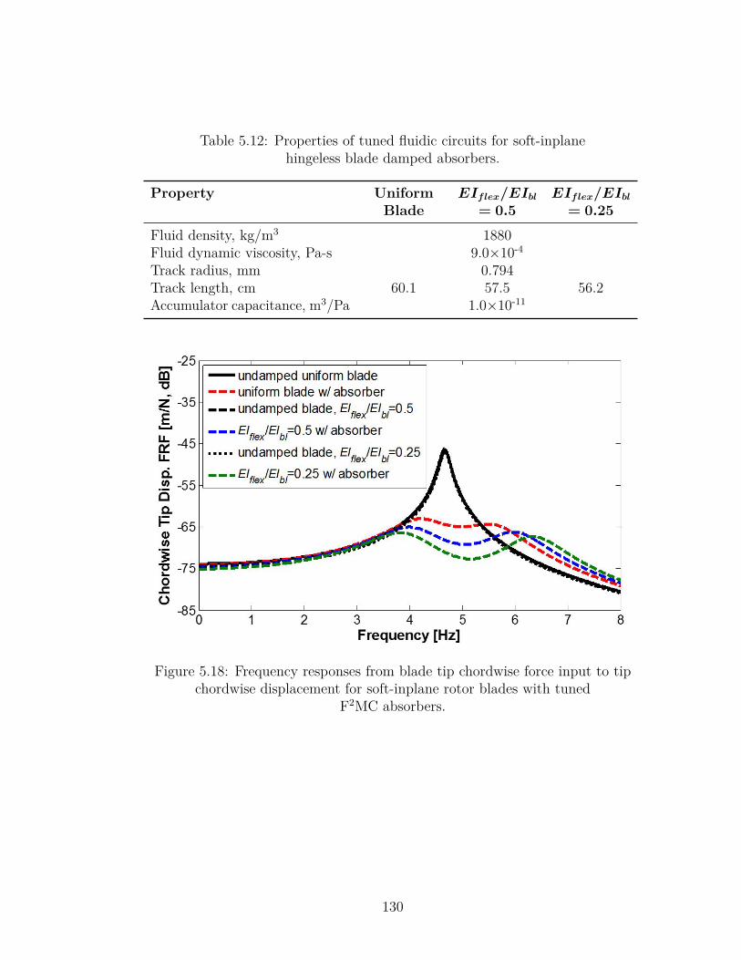
Table 5.12: Properties of tuned fluidic circuits for soft-inplanehingeless blade damped absorbers.
Property UniformBlade
EIflex/EIbl
= 0.5EIflex/EIbl
= 0.25
Fluid density, kg/m3 1880Fluid dynamic viscosity, Pa-s 9.0×10⁻⁴
Track radius, mm 0.794Track length, cm 60.1 57.5 56.2Accumulator capacitance, m3/Pa 1.0×10⁻¹¹
Figure 5.18: Frequency responses from blade tip chordwise force input to tipchordwise displacement for soft-inplane rotor blades with tuned
F2MC absorbers.
130
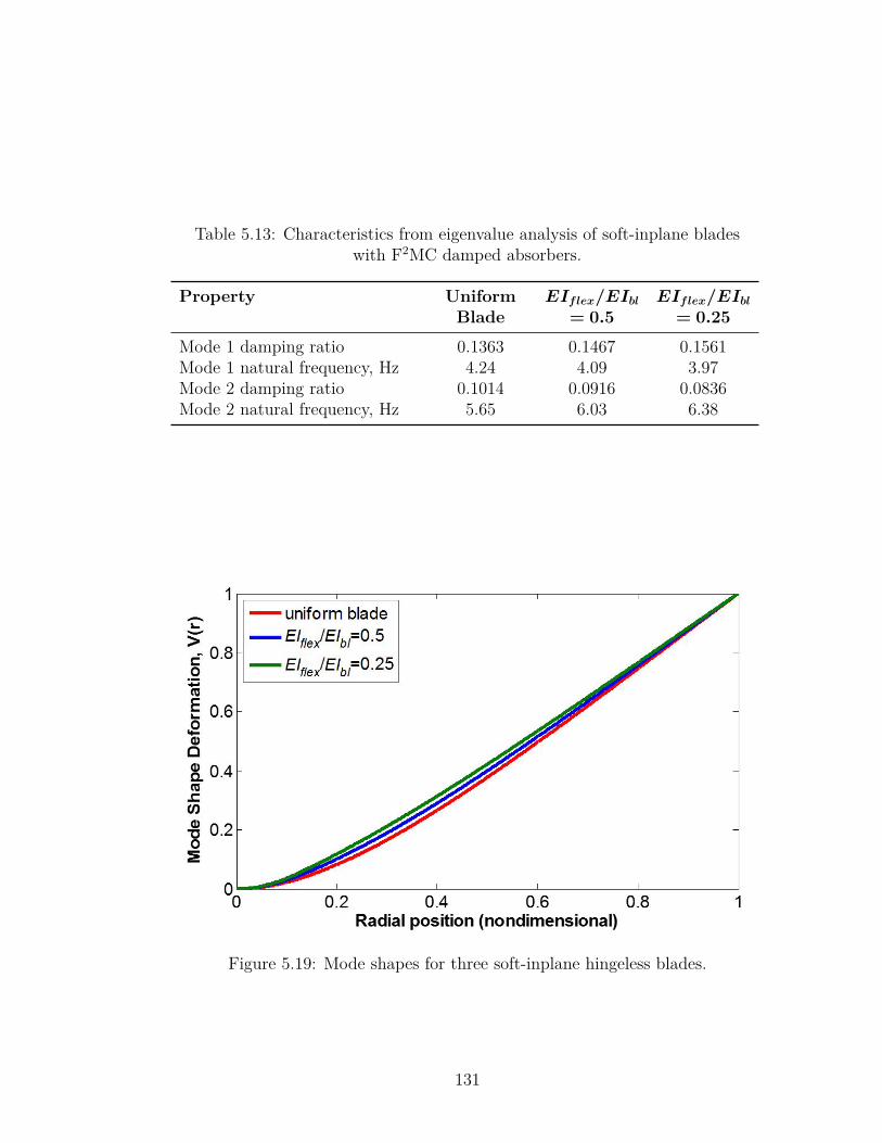
Table 5.13: Characteristics from eigenvalue analysis of soft-inplane bladeswith F2MC damped absorbers.
Property UniformBlade
EIflex/EIbl
= 0.5EIflex/EIbl
= 0.25
Mode 1 damping ratio 0.1363 0.1467 0.1561Mode 1 natural frequency, Hz 4.24 4.09 3.97Mode 2 damping ratio 0.1014 0.0916 0.0836Mode 2 natural frequency, Hz 5.65 6.03 6.38
Figure 5.19: Mode shapes for three soft-inplane hingeless blades.
131
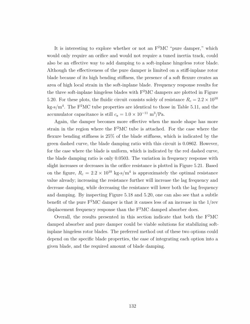
It is interesting to explore whether or not an F2MC “pure damper,” whichwould only require an orifice and would not require a tuned inertia track, couldalso be an effective way to add damping to a soft-inplane hingeless rotor blade.Although the effectiveness of the pure damper is limited on a stiff-inplane rotorblade because of its high bending stiffness, the presence of a soft flexure creates anarea of high local strain in the soft-inplane blade. Frequency response results forthe three soft-inplane hingeless blades with F2MC dampers are plotted in Figure5.20. For these plots, the fluidic circuit consists solely of resistance Rc = 2.2× 10¹⁰
kg-s/m4. The F2MC tube properties are identical to those in Table 5.11, and theaccumulator capacitance is still ca = 1.0× 10⁻¹¹ m3/Pa.
Again, the damper becomes more effective when the mode shape has morestrain in the region where the F2MC tube is attached. For the case where theflexure bending stiffness is 25% of the blade stiffness, which is indicated by thegreen dashed curve, the blade damping ratio with this circuit is 0.0862. However,for the case where the blade is uniform, which is indicated by the red dashed curve,the blade damping ratio is only 0.0503. The variation in frequency response withslight increases or decreases in the orifice resistance is plotted in Figure 5.21. Basedon the figure, Rc = 2.2 × 10¹⁰ kg-s/m4 is approximately the optimal resistancevalue already; increasing the resistance further will increase the lag frequency anddecrease damping, while decreasing the resistance will lower both the lag frequencyand damping. By inspecting Figure 5.18 and 5.20, one can also see that a subtlebenefit of the pure F2MC damper is that it causes less of an increase in the 1/revdisplacement frequency response than the F2MC damped absorber does.
Overall, the results presented in this section indicate that both the F2MCdamped absorber and pure damper could be viable solutions for stabilizing soft-inplane hingeless rotor blades. The preferred method out of these two options coulddepend on the specific blade properties, the ease of integrating each option into agiven blade, and the required amount of blade damping.
132
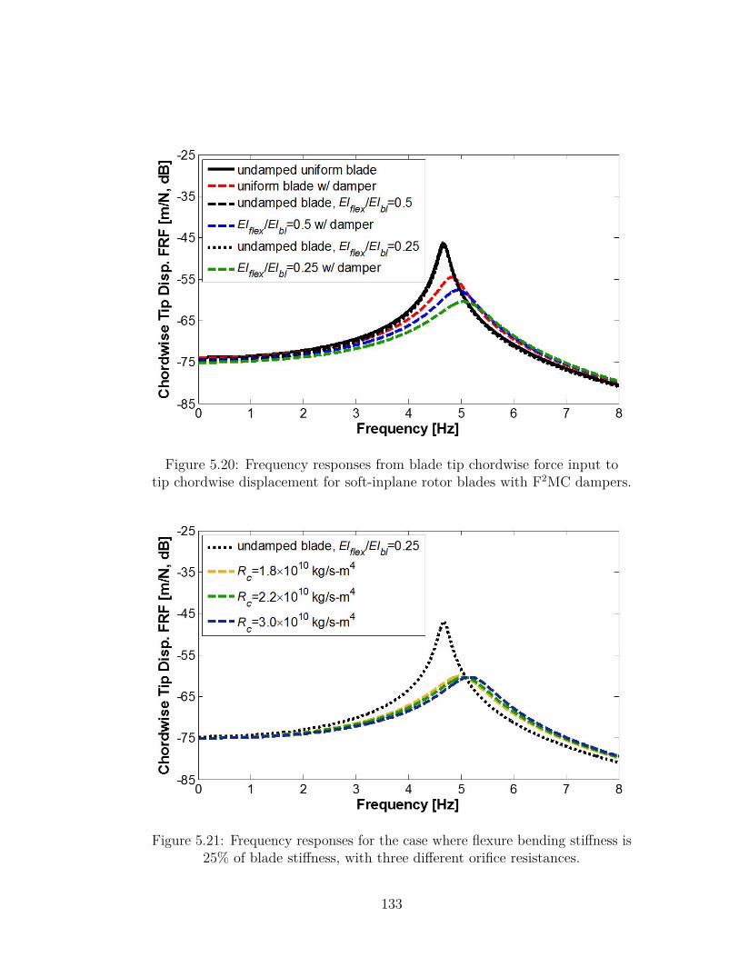
Figure 5.20: Frequency responses from blade tip chordwise force input totip chordwise displacement for soft-inplane rotor blades with F2MC dampers.
Figure 5.21: Frequency responses for the case where flexure bending stiffness is25% of blade stiffness, with three different orifice resistances.
133
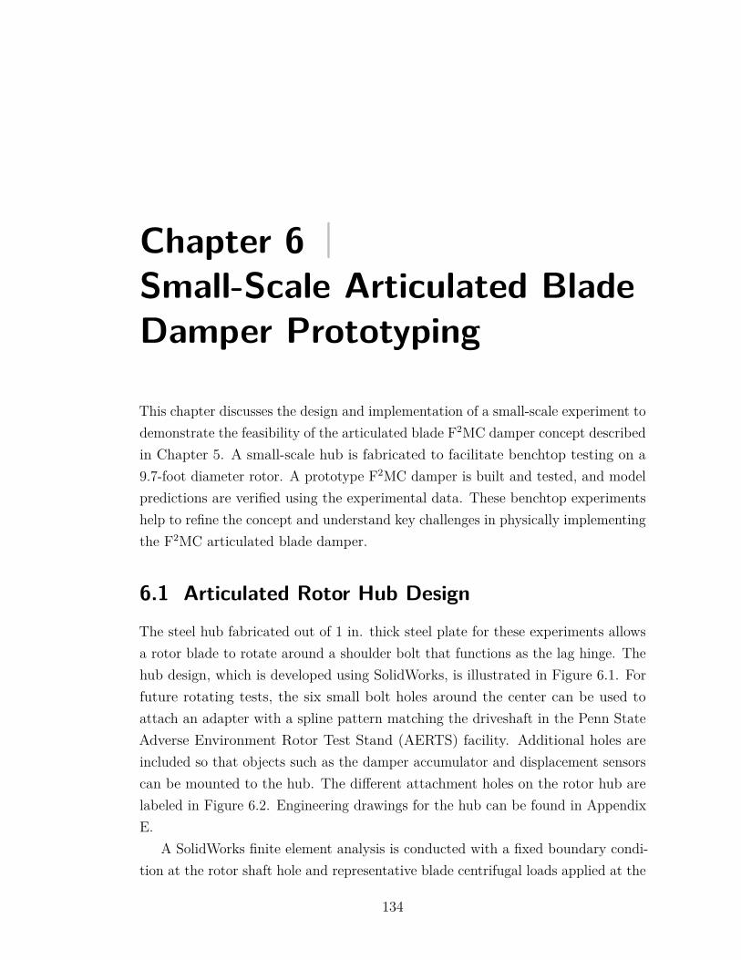
Chapter 6 |Small-Scale Articulated BladeDamper Prototyping
This chapter discusses the design and implementation of a small-scale experiment todemonstrate the feasibility of the articulated blade F2MC damper concept describedin Chapter 5. A small-scale hub is fabricated to facilitate benchtop testing on a9.7-foot diameter rotor. A prototype F2MC damper is built and tested, and modelpredictions are verified using the experimental data. These benchtop experimentshelp to refine the concept and understand key challenges in physically implementingthe F2MC articulated blade damper.
6.1 Articulated Rotor Hub DesignThe steel hub fabricated out of 1 in. thick steel plate for these experiments allowsa rotor blade to rotate around a shoulder bolt that functions as the lag hinge. Thehub design, which is developed using SolidWorks, is illustrated in Figure 6.1. Forfuture rotating tests, the six small bolt holes around the center can be used toattach an adapter with a spline pattern matching the driveshaft in the Penn StateAdverse Environment Rotor Test Stand (AERTS) facility. Additional holes areincluded so that objects such as the damper accumulator and displacement sensorscan be mounted to the hub. The different attachment holes on the rotor hub arelabeled in Figure 6.2. Engineering drawings for the hub can be found in AppendixE.
A SolidWorks finite element analysis is conducted with a fixed boundary condi-tion at the rotor shaft hole and representative blade centrifugal loads applied at the
134
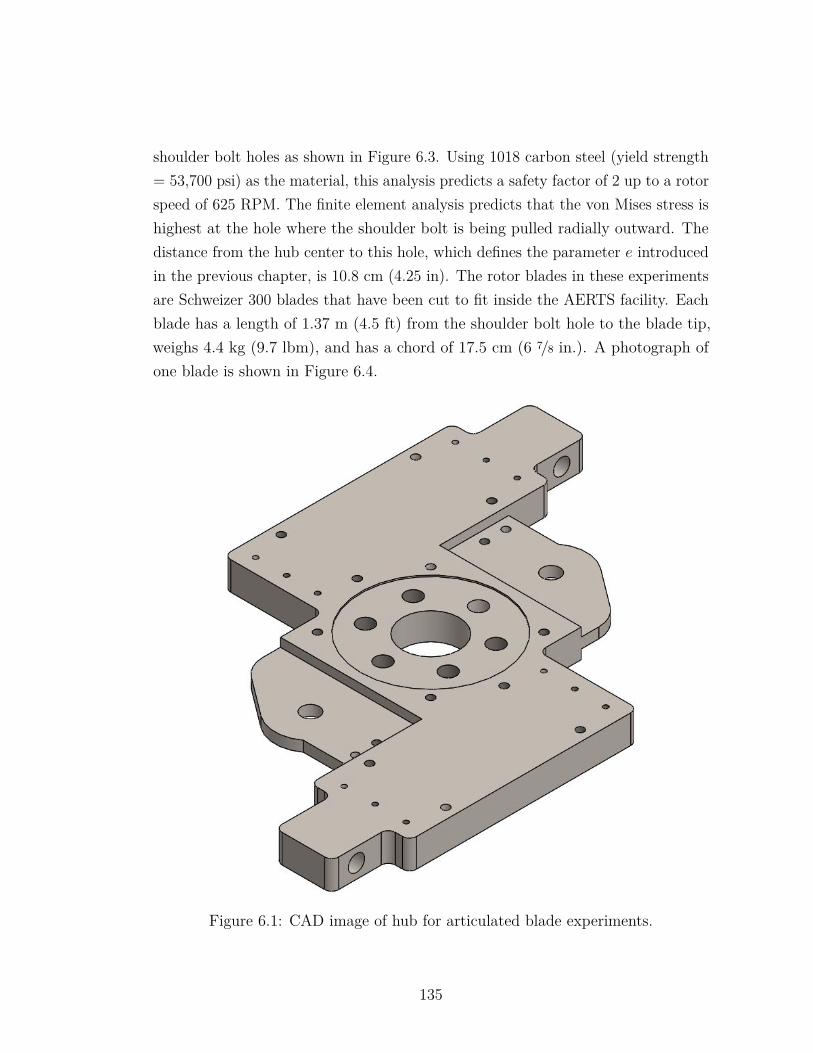
shoulder bolt holes as shown in Figure 6.3. Using 1018 carbon steel (yield strength= 53,700 psi) as the material, this analysis predicts a safety factor of 2 up to a rotorspeed of 625 RPM. The finite element analysis predicts that the von Mises stress ishighest at the hole where the shoulder bolt is being pulled radially outward. Thedistance from the hub center to this hole, which defines the parameter e introducedin the previous chapter, is 10.8 cm (4.25 in). The rotor blades in these experimentsare Schweizer 300 blades that have been cut to fit inside the AERTS facility. Eachblade has a length of 1.37 m (4.5 ft) from the shoulder bolt hole to the blade tip,weighs 4.4 kg (9.7 lbm), and has a chord of 17.5 cm (6 7/8 in.). A photograph ofone blade is shown in Figure 6.4.
Figure 6.1: CAD image of hub for articulated blade experiments.
135
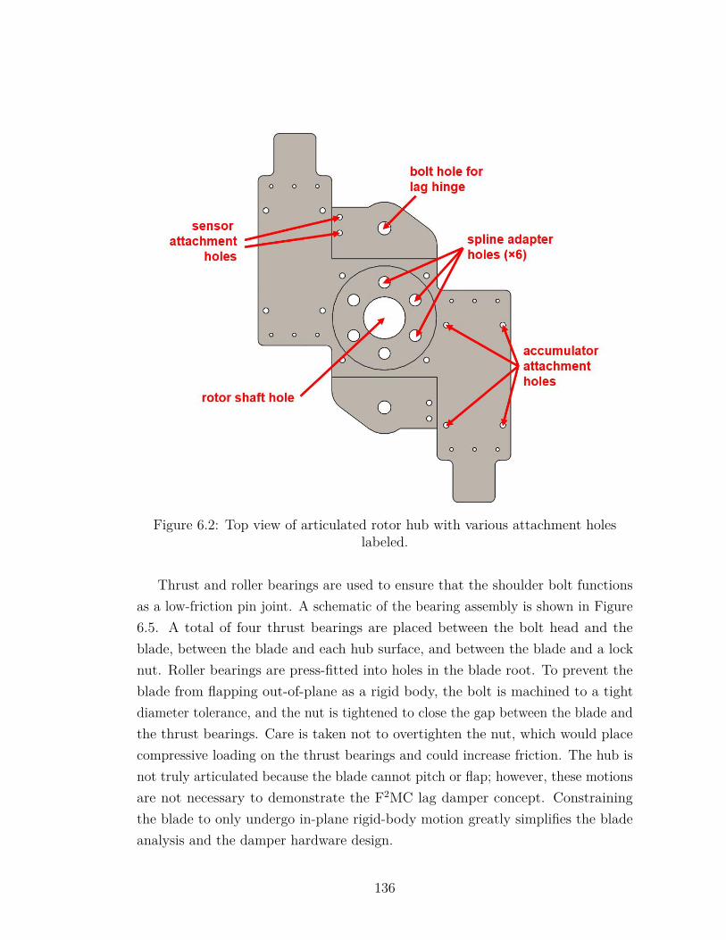
Figure 6.2: Top view of articulated rotor hub with various attachment holeslabeled.
Thrust and roller bearings are used to ensure that the shoulder bolt functionsas a low-friction pin joint. A schematic of the bearing assembly is shown in Figure6.5. A total of four thrust bearings are placed between the bolt head and theblade, between the blade and each hub surface, and between the blade and a locknut. Roller bearings are press-fitted into holes in the blade root. To prevent theblade from flapping out-of-plane as a rigid body, the bolt is machined to a tightdiameter tolerance, and the nut is tightened to close the gap between the blade andthe thrust bearings. Care is taken not to overtighten the nut, which would placecompressive loading on the thrust bearings and could increase friction. The hub isnot truly articulated because the blade cannot pitch or flap; however, these motionsare not necessary to demonstrate the F2MC lag damper concept. Constrainingthe blade to only undergo in-plane rigid-body motion greatly simplifies the bladeanalysis and the damper hardware design.
136
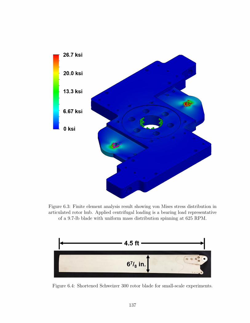
Figure 6.3: Finite element analysis result showing von Mises stress distribution inarticulated rotor hub. Applied centrifugal loading is a bearing load representative
of a 9.7-lb blade with uniform mass distribution spinning at 625 RPM.
Figure 6.4: Shortened Schweizer 300 rotor blade for small-scale experiments.
137
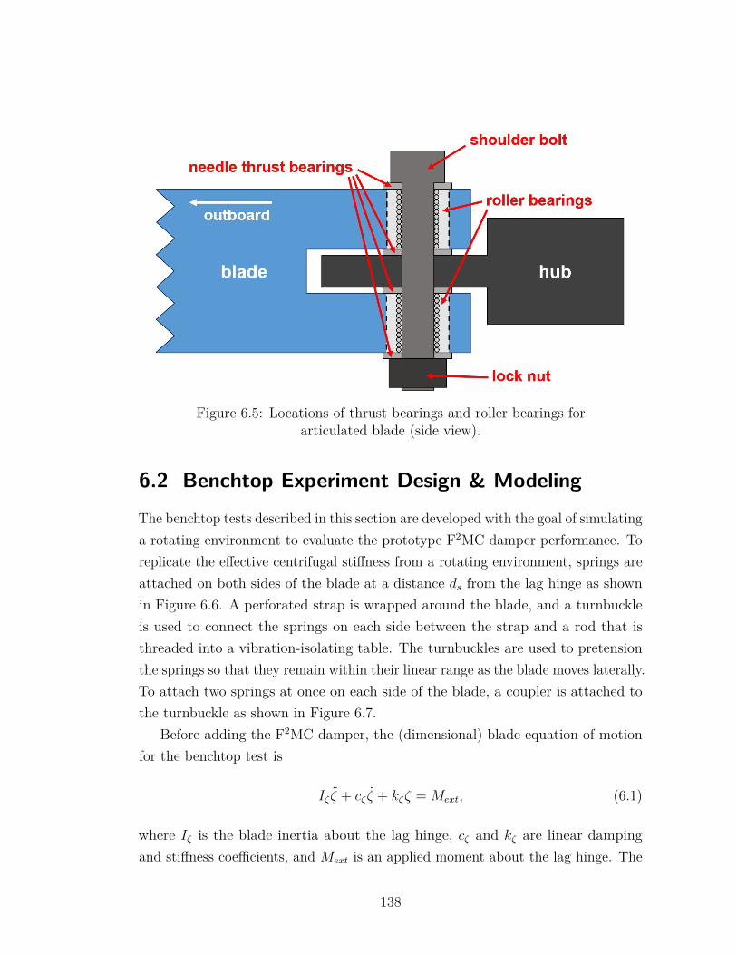
Figure 6.5: Locations of thrust bearings and roller bearings forarticulated blade (side view).
6.2 Benchtop Experiment Design & ModelingThe benchtop tests described in this section are developed with the goal of simulatinga rotating environment to evaluate the prototype F2MC damper performance. Toreplicate the effective centrifugal stiffness from a rotating environment, springs areattached on both sides of the blade at a distance ds from the lag hinge as shownin Figure 6.6. A perforated strap is wrapped around the blade, and a turnbuckleis used to connect the springs on each side between the strap and a rod that isthreaded into a vibration-isolating table. The turnbuckles are used to pretensionthe springs so that they remain within their linear range as the blade moves laterally.To attach two springs at once on each side of the blade, a coupler is attached tothe turnbuckle as shown in Figure 6.7.
Before adding the F2MC damper, the (dimensional) blade equation of motionfor the benchtop test is
Iζ ζ + cζ ζ + kζζ = Mext, (6.1)
where Iζ is the blade inertia about the lag hinge, cζ and kζ are linear dampingand stiffness coefficients, and Mext is an applied moment about the lag hinge. The
138
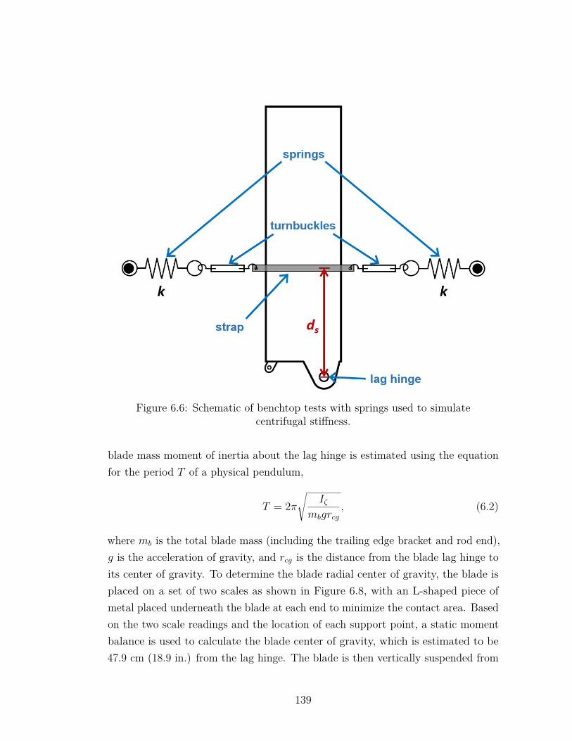
Figure 6.6: Schematic of benchtop tests with springs used to simulatecentrifugal stiffness.
blade mass moment of inertia about the lag hinge is estimated using the equationfor the period T of a physical pendulum,
T = 2π√
Iζmbgrcg
, (6.2)
where mb is the total blade mass (including the trailing edge bracket and rod end),g is the acceleration of gravity, and rcg is the distance from the blade lag hinge toits center of gravity. To determine the blade radial center of gravity, the blade isplaced on a set of two scales as shown in Figure 6.8, with an L-shaped piece ofmetal placed underneath the blade at each end to minimize the contact area. Basedon the two scale readings and the location of each support point, a static momentbalance is used to calculate the blade center of gravity, which is estimated to be47.9 cm (18.9 in.) from the lag hinge. The blade is then vertically suspended from
139
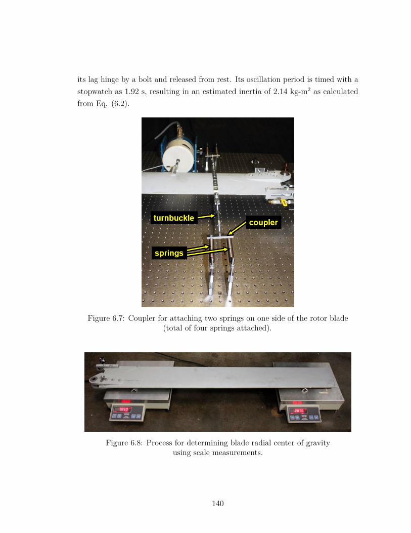
its lag hinge by a bolt and released from rest. Its oscillation period is timed with astopwatch as 1.92 s, resulting in an estimated inertia of 2.14 kg-m2 as calculatedfrom Eq. (6.2).
Figure 6.7: Coupler for attaching two springs on one side of the rotor blade(total of four springs attached).
Figure 6.8: Process for determining blade radial center of gravityusing scale measurements.
140
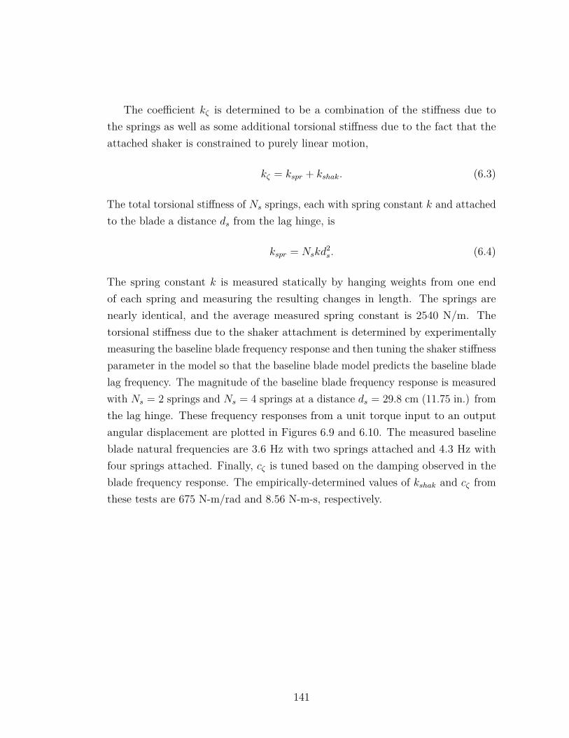
The coefficient kζ is determined to be a combination of the stiffness due tothe springs as well as some additional torsional stiffness due to the fact that theattached shaker is constrained to purely linear motion,
kζ = kspr + kshak. (6.3)
The total torsional stiffness of Ns springs, each with spring constant k and attachedto the blade a distance ds from the lag hinge, is
kspr = Nskd2s. (6.4)
The spring constant k is measured statically by hanging weights from one endof each spring and measuring the resulting changes in length. The springs arenearly identical, and the average measured spring constant is 2540 N/m. Thetorsional stiffness due to the shaker attachment is determined by experimentallymeasuring the baseline blade frequency response and then tuning the shaker stiffnessparameter in the model so that the baseline blade model predicts the baseline bladelag frequency. The magnitude of the baseline blade frequency response is measuredwith Ns = 2 springs and Ns = 4 springs at a distance ds = 29.8 cm (11.75 in.) fromthe lag hinge. These frequency responses from a unit torque input to an outputangular displacement are plotted in Figures 6.9 and 6.10. The measured baselineblade natural frequencies are 3.6 Hz with two springs attached and 4.3 Hz withfour springs attached. Finally, cζ is tuned based on the damping observed in theblade frequency response. The empirically-determined values of kshak and cζ fromthese tests are 675 N-m/rad and 8.56 N-m-s, respectively.
141
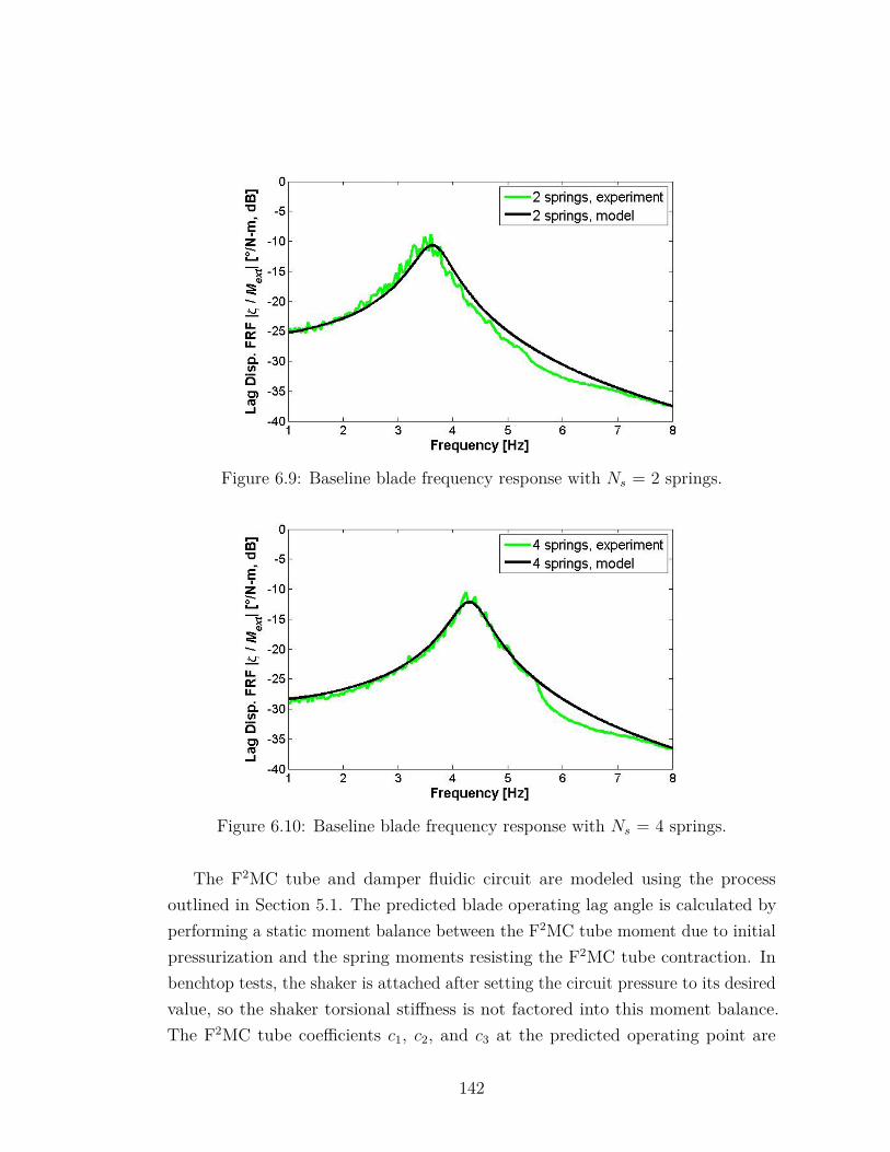
Figure 6.9: Baseline blade frequency response with Ns = 2 springs.
Figure 6.10: Baseline blade frequency response with Ns = 4 springs.
The F2MC tube and damper fluidic circuit are modeled using the processoutlined in Section 5.1. The predicted blade operating lag angle is calculated byperforming a static moment balance between the F2MC tube moment due to initialpressurization and the spring moments resisting the F2MC tube contraction. Inbenchtop tests, the shaker is attached after setting the circuit pressure to its desiredvalue, so the shaker torsional stiffness is not factored into this moment balance.The F2MC tube coefficients c1, c2, and c3 at the predicted operating point are
142
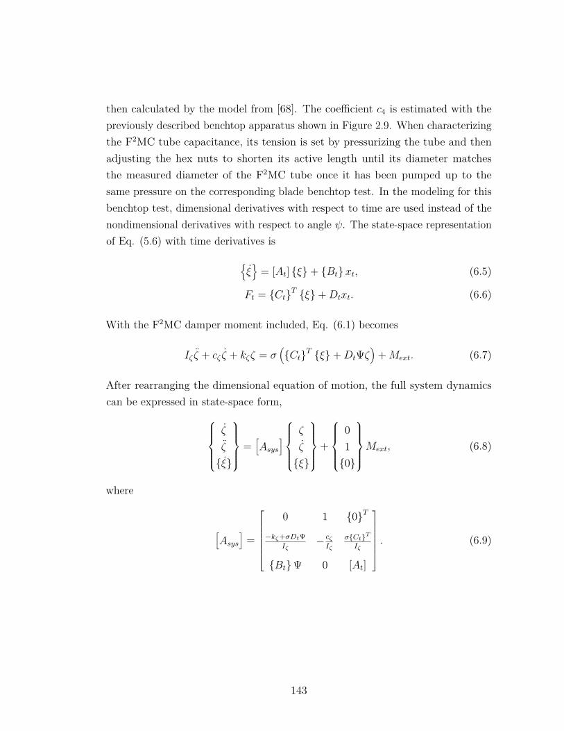
then calculated by the model from [68]. The coefficient c4 is estimated with thepreviously described benchtop apparatus shown in Figure 2.9. When characterizingthe F2MC tube capacitance, its tension is set by pressurizing the tube and thenadjusting the hex nuts to shorten its active length until its diameter matchesthe measured diameter of the F2MC tube once it has been pumped up to thesame pressure on the corresponding blade benchtop test. In the modeling for thisbenchtop test, dimensional derivatives with respect to time are used instead of thenondimensional derivatives with respect to angle ψ. The state-space representationof Eq. (5.6) with time derivatives is
ξ
= [At] ξ+ Btxt, (6.5)
Ft = CtT ξ+Dtxt. (6.6)
With the F2MC damper moment included, Eq. (6.1) becomes
Iζ ζ + cζ ζ + kζζ = σ(CtT ξ+DtΨζ
)+Mext. (6.7)
After rearranging the dimensional equation of motion, the full system dynamicscan be expressed in state-space form,
ζ
ζ
ξ
=[Asys
]ζ
ζ
ξ
+
010
Mext, (6.8)
where
[Asys
]=
0 1 0T
−kζ+σDtΨIζ
− cζIζ
σCtTIζ
BtΨ 0 [At]
. (6.9)
143
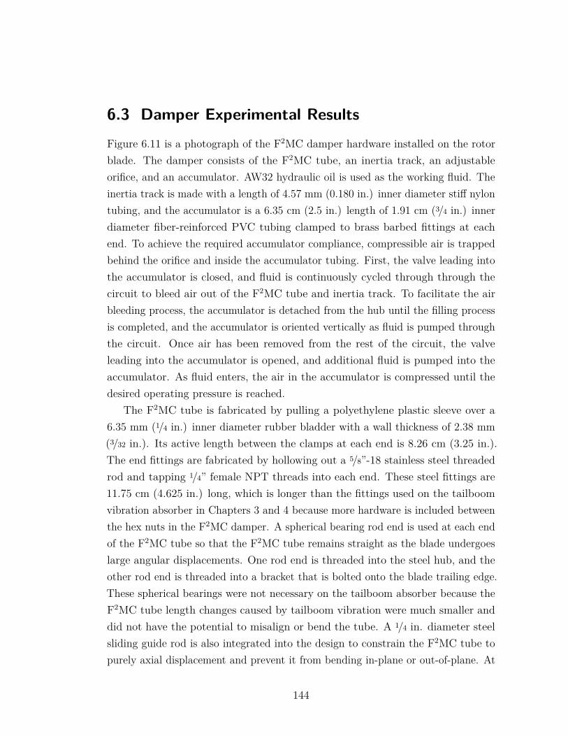
6.3 Damper Experimental ResultsFigure 6.11 is a photograph of the F2MC damper hardware installed on the rotorblade. The damper consists of the F2MC tube, an inertia track, an adjustableorifice, and an accumulator. AW32 hydraulic oil is used as the working fluid. Theinertia track is made with a length of 4.57 mm (0.180 in.) inner diameter stiff nylontubing, and the accumulator is a 6.35 cm (2.5 in.) length of 1.91 cm (3/4 in.) innerdiameter fiber-reinforced PVC tubing clamped to brass barbed fittings at eachend. To achieve the required accumulator compliance, compressible air is trappedbehind the orifice and inside the accumulator tubing. First, the valve leading intothe accumulator is closed, and fluid is continuously cycled through through thecircuit to bleed air out of the F2MC tube and inertia track. To facilitate the airbleeding process, the accumulator is detached from the hub until the filling processis completed, and the accumulator is oriented vertically as fluid is pumped throughthe circuit. Once air has been removed from the rest of the circuit, the valveleading into the accumulator is opened, and additional fluid is pumped into theaccumulator. As fluid enters, the air in the accumulator is compressed until thedesired operating pressure is reached.
The F2MC tube is fabricated by pulling a polyethylene plastic sleeve over a6.35 mm (1/4 in.) inner diameter rubber bladder with a wall thickness of 2.38 mm(3/32 in.). Its active length between the clamps at each end is 8.26 cm (3.25 in.).The end fittings are fabricated by hollowing out a 5/8”-18 stainless steel threadedrod and tapping 1/4” female NPT threads into each end. These steel fittings are11.75 cm (4.625 in.) long, which is longer than the fittings used on the tailboomvibration absorber in Chapters 3 and 4 because more hardware is included betweenthe hex nuts in the F2MC damper. A spherical bearing rod end is used at each endof the F2MC tube so that the F2MC tube remains straight as the blade undergoeslarge angular displacements. One rod end is threaded into the steel hub, and theother rod end is threaded into a bracket that is bolted onto the blade trailing edge.These spherical bearings were not necessary on the tailboom absorber because theF2MC tube length changes caused by tailboom vibration were much smaller anddid not have the potential to misalign or bend the tube. A 1/4 in. diameter steelsliding guide rod is also integrated into the design to constrain the F2MC tube topurely axial displacement and prevent it from bending in-plane or out-of-plane. At
144
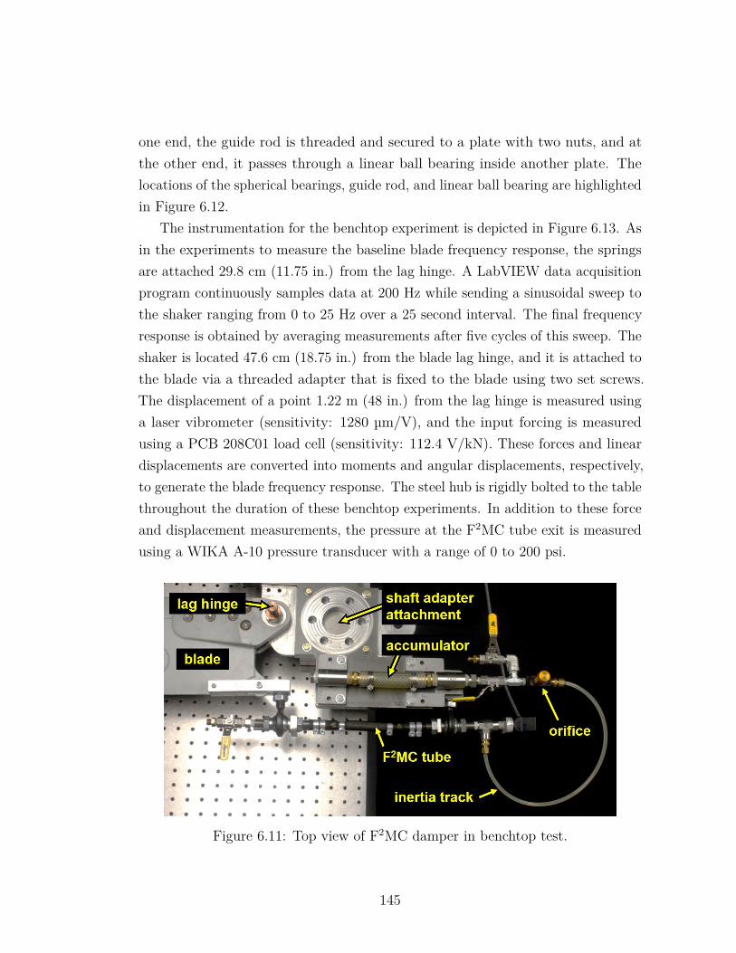
one end, the guide rod is threaded and secured to a plate with two nuts, and atthe other end, it passes through a linear ball bearing inside another plate. Thelocations of the spherical bearings, guide rod, and linear ball bearing are highlightedin Figure 6.12.
The instrumentation for the benchtop experiment is depicted in Figure 6.13. Asin the experiments to measure the baseline blade frequency response, the springsare attached 29.8 cm (11.75 in.) from the lag hinge. A LabVIEW data acquisitionprogram continuously samples data at 200 Hz while sending a sinusoidal sweep tothe shaker ranging from 0 to 25 Hz over a 25 second interval. The final frequencyresponse is obtained by averaging measurements after five cycles of this sweep. Theshaker is located 47.6 cm (18.75 in.) from the blade lag hinge, and it is attached tothe blade via a threaded adapter that is fixed to the blade using two set screws.The displacement of a point 1.22 m (48 in.) from the lag hinge is measured usinga laser vibrometer (sensitivity: 1280 µm/V), and the input forcing is measuredusing a PCB 208C01 load cell (sensitivity: 112.4 V/kN). These forces and lineardisplacements are converted into moments and angular displacements, respectively,to generate the blade frequency response. The steel hub is rigidly bolted to the tablethroughout the duration of these benchtop experiments. In addition to these forceand displacement measurements, the pressure at the F2MC tube exit is measuredusing a WIKA A-10 pressure transducer with a range of 0 to 200 psi.
Figure 6.11: Top view of F2MC damper in benchtop test.
145
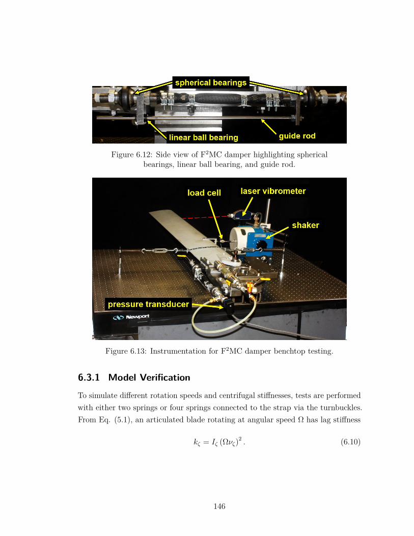
Figure 6.12: Side view of F2MC damper highlighting sphericalbearings, linear ball bearing, and guide rod.
Figure 6.13: Instrumentation for F2MC damper benchtop testing.
6.3.1 Model Verification
To simulate different rotation speeds and centrifugal stiffnesses, tests are performedwith either two springs or four springs connected to the strap via the turnbuckles.From Eq. (5.1), an articulated blade rotating at angular speed Ω has lag stiffness
kζ = Iζ (Ωνζ)2 . (6.10)
146
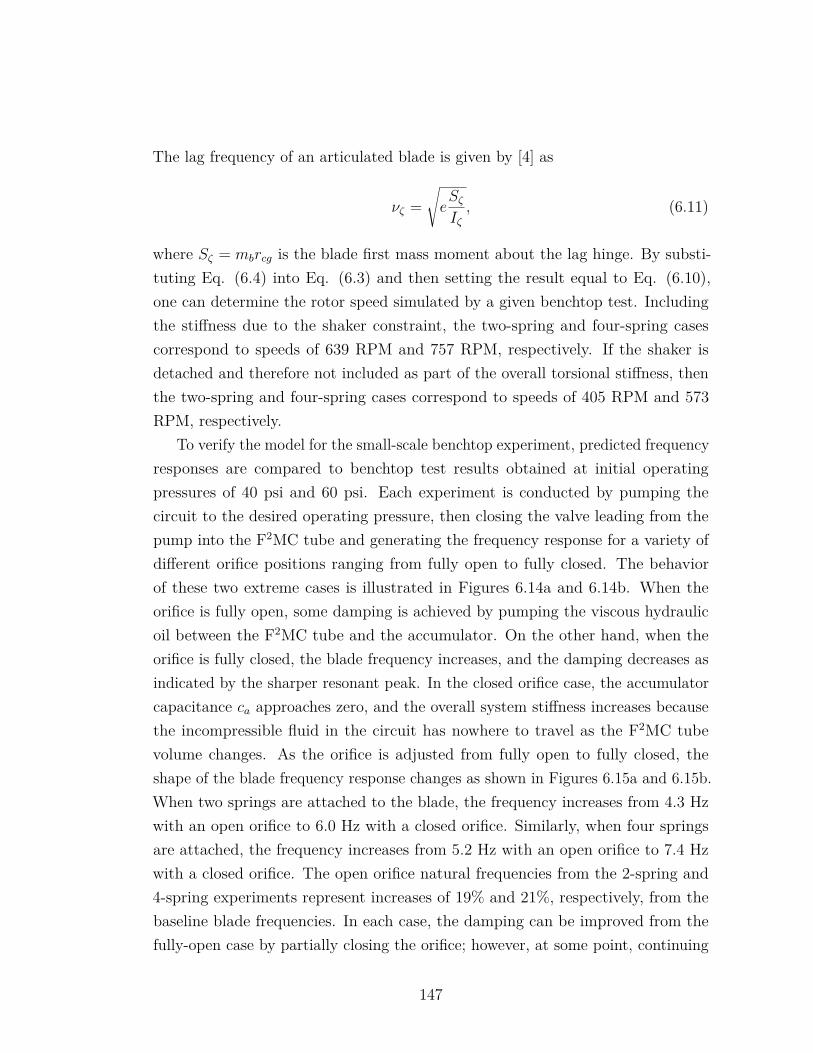
The lag frequency of an articulated blade is given by [4] as
νζ =√eSζIζ, (6.11)
where Sζ = mbrcg is the blade first mass moment about the lag hinge. By substi-tuting Eq. (6.4) into Eq. (6.3) and then setting the result equal to Eq. (6.10),one can determine the rotor speed simulated by a given benchtop test. Includingthe stiffness due to the shaker constraint, the two-spring and four-spring casescorrespond to speeds of 639 RPM and 757 RPM, respectively. If the shaker isdetached and therefore not included as part of the overall torsional stiffness, thenthe two-spring and four-spring cases correspond to speeds of 405 RPM and 573RPM, respectively.
To verify the model for the small-scale benchtop experiment, predicted frequencyresponses are compared to benchtop test results obtained at initial operatingpressures of 40 psi and 60 psi. Each experiment is conducted by pumping thecircuit to the desired operating pressure, then closing the valve leading from thepump into the F2MC tube and generating the frequency response for a variety ofdifferent orifice positions ranging from fully open to fully closed. The behaviorof these two extreme cases is illustrated in Figures 6.14a and 6.14b. When theorifice is fully open, some damping is achieved by pumping the viscous hydraulicoil between the F2MC tube and the accumulator. On the other hand, when theorifice is fully closed, the blade frequency increases, and the damping decreases asindicated by the sharper resonant peak. In the closed orifice case, the accumulatorcapacitance ca approaches zero, and the overall system stiffness increases becausethe incompressible fluid in the circuit has nowhere to travel as the F2MC tubevolume changes. As the orifice is adjusted from fully open to fully closed, theshape of the blade frequency response changes as shown in Figures 6.15a and 6.15b.When two springs are attached to the blade, the frequency increases from 4.3 Hzwith an open orifice to 6.0 Hz with a closed orifice. Similarly, when four springsare attached, the frequency increases from 5.2 Hz with an open orifice to 7.4 Hzwith a closed orifice. The open orifice natural frequencies from the 2-spring and4-spring experiments represent increases of 19% and 21%, respectively, from thebaseline blade frequencies. In each case, the damping can be improved from thefully-open case by partially closing the orifice; however, at some point, continuing
147
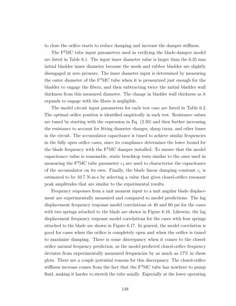
to close the orifice starts to reduce damping and increase the damper stiffness.The F2MC tube input parameters used in verifying the blade-damper model
are listed in Table 6.1. The input inner diameter value is larger than the 6.35 mminitial bladder inner diameter because the mesh and rubber bladder are slightlydisengaged at zero pressure. The inner diameter input is determined by measuringthe outer diameter of the F2MC tube when it is pressurized just enough for thebladder to engage the fibers, and then subtracting twice the initial bladder wallthickness from this measured diameter. The change in bladder wall thickness as itexpands to engage with the fibers is negligible.
The model circuit input parameters for each test case are listed in Table 6.2.The optimal orifice position is identified empirically in each test. Resistance valuesare tuned by starting with the expression in Eq. (2.50) and then further increasingthe resistance to account for fitting diameter changes, sharp turns, and other lossesin the circuit. The accumulator capacitance is tuned to achieve similar frequenciesin the fully open orifice cases, since its compliance determines the lower bound forthe blade frequency with the F2MC damper installed. To ensure that the modelcapacitance value is reasonable, static benchtop tests similar to the ones used inmeasuring the F2MC tube parameter c4 are used to characterize the capacitanceof the accumulator on its own. Finally, the blade linear damping constant cζ isestimated to be 10.7 N-m-s by selecting a value that gives closed-orifice resonantpeak amplitudes that are similar to the experimental results.
Frequency responses from a unit moment input to a unit angular blade displace-ment are experimentally measured and compared to model predictions. The lagdisplacement frequency response model correlations at 40 and 60 psi for the caseswith two springs attached to the blade are shown in Figure 6.16. Likewise, the lagdisplacement frequency response model correlations for the cases with four springsattached to the blade are shown in Figure 6.17. In general, the model correlation isgood for cases when the orifice is completely open and when the orifice is tunedto maximize damping. There is some discrepancy when it comes to the closed-orifice natural frequency prediction, as the model-predicted closed-orifice frequencydeviates from experimentally measured frequencies by as much as 17% in theseplots. There are a couple potential reasons for this discrepancy. The closed-orificestiffness increase comes from the fact that the F2MC tube has nowhere to pumpfluid, making it harder to stretch the tube axially. Especially at the lower operating
148
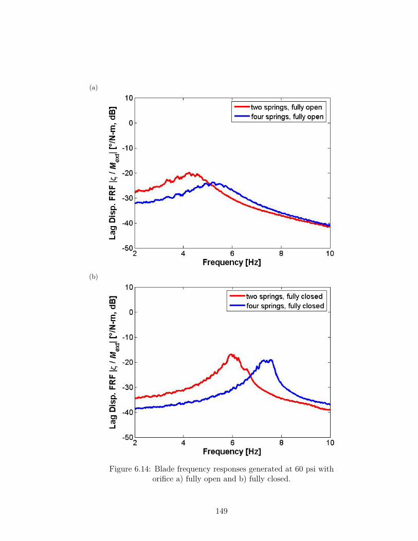
(a)
(b)
Figure 6.14: Blade frequency responses generated at 60 psi withorifice a) fully open and b) fully closed.
149
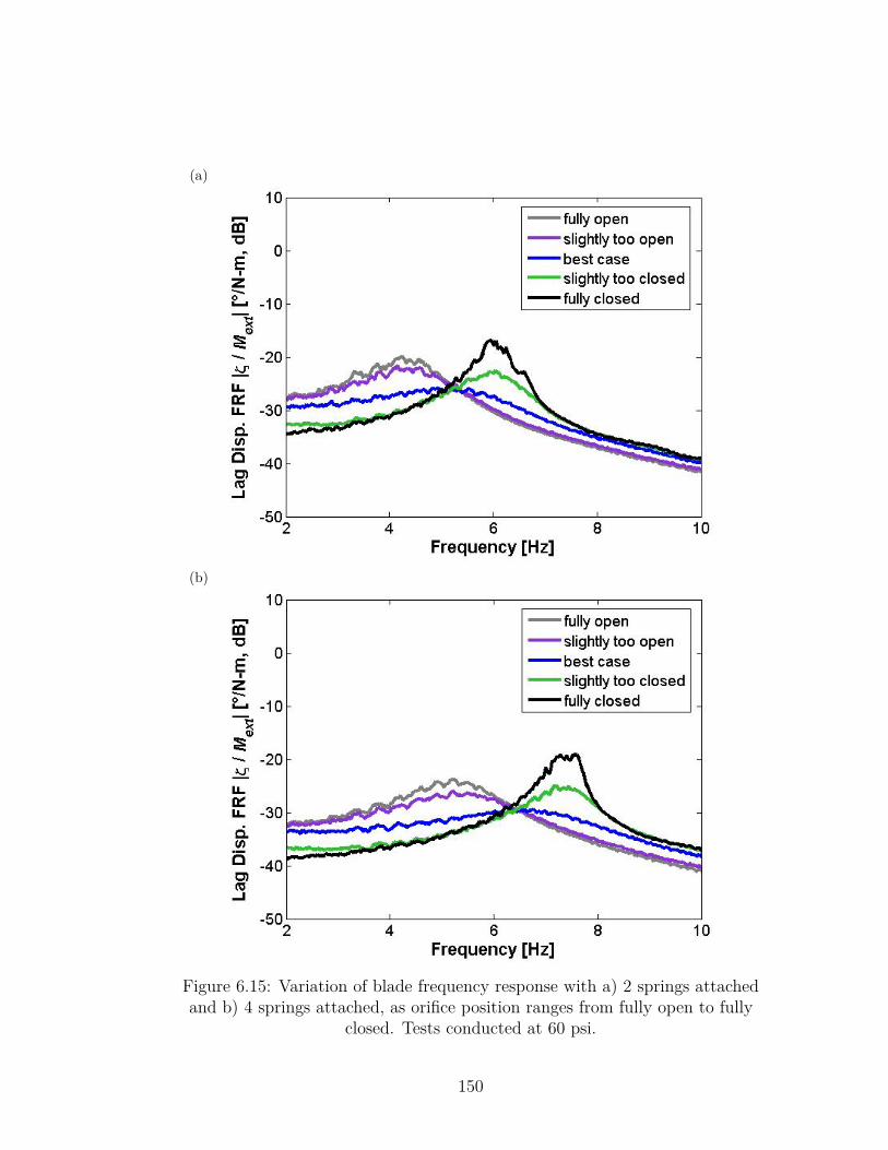
(a)
(b)
Figure 6.15: Variation of blade frequency response with a) 2 springs attachedand b) 4 springs attached, as orifice position ranges from fully open to fully
closed. Tests conducted at 60 psi.
150
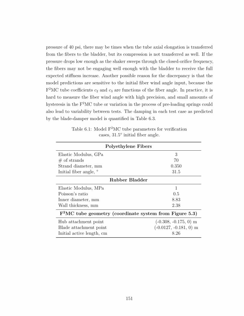
pressure of 40 psi, there may be times when the tube axial elongation is transferredfrom the fibers to the bladder, but its compression is not transferred as well. If thepressure drops low enough as the shaker sweeps through the closed-orifice frequency,the fibers may not be engaging well enough with the bladder to receive the fullexpected stiffness increase. Another possible reason for the discrepancy is that themodel predictions are sensitive to the initial fiber wind angle input, because theF2MC tube coefficients c2 and c3 are functions of the fiber angle. In practice, it ishard to measure the fiber wind angle with high precision, and small amounts ofhysteresis in the F2MC tube or variation in the process of pre-loading springs couldalso lead to variability between tests. The damping in each test case as predictedby the blade-damper model is quantified in Table 6.3.
Table 6.1: Model F2MC tube parameters for verificationcases, 31.5° initial fiber angle.
Polyethylene Fibers
Elastic Modulus, GPa 3# of strands 70Strand diameter, mm 0.350Initial fiber angle, ° 31.5
Rubber Bladder
Elastic Modulus, MPa 1Poisson’s ratio 0.5Inner diameter, mm 8.83Wall thickness, mm 2.38F2MC tube geometry (coordinate system from Figure 5.3)
Hub attachment point (-0.308, -0.175, 0) mBlade attachment point (-0.0127, -0.181, 0) mInitial active length, cm 8.26
151
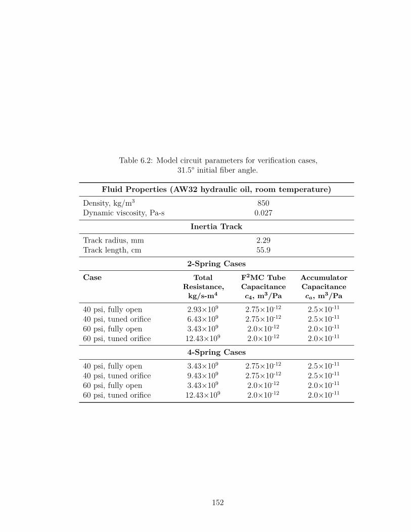
Table 6.2: Model circuit parameters for verification cases,31.5° initial fiber angle.
Fluid Properties (AW32 hydraulic oil, room temperature)
Density, kg/m3 850Dynamic viscosity, Pa-s 0.027
Inertia Track
Track radius, mm 2.29Track length, cm 55.9
2-Spring Cases
Case TotalResistance,
kg/s-m4
F2MC TubeCapacitancec4, m3/Pa
AccumulatorCapacitanceca, m3/Pa
40 psi, fully open 2.93×10⁹ 2.75×10⁻¹² 2.5×10⁻¹¹
40 psi, tuned orifice 6.43×10⁹ 2.75×10⁻¹² 2.5×10⁻¹¹
60 psi, fully open 3.43×10⁹ 2.0×10⁻¹² 2.0×10⁻¹¹
60 psi, tuned orifice 12.43×10⁹ 2.0×10⁻¹² 2.0×10⁻¹¹
4-Spring Cases
40 psi, fully open 3.43×10⁹ 2.75×10⁻¹² 2.5×10⁻¹¹
40 psi, tuned orifice 9.43×10⁹ 2.75×10⁻¹² 2.5×10⁻¹¹
60 psi, fully open 3.43×10⁹ 2.0×10⁻¹² 2.0×10⁻¹¹
60 psi, tuned orifice 12.43×10⁹ 2.0×10⁻¹² 2.0×10⁻¹¹
152
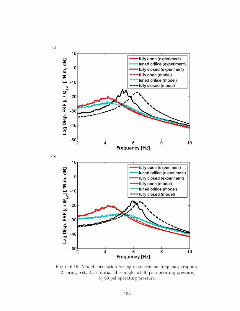
(a)
(b)
Figure 6.16: Model correlation for lag displacement frequency response,2-spring test, 31.5° initial fiber angle, a) 40 psi operating pressure,
b) 60 psi operating pressure.
153
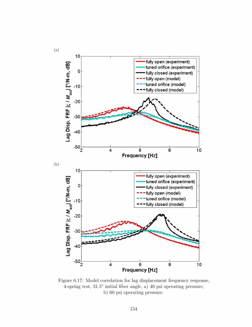
(a)
(b)
Figure 6.17: Model correlation for lag displacement frequency response,4-spring test, 31.5° initial fiber angle, a) 40 psi operating pressure,
b) 60 psi operating pressure.
154
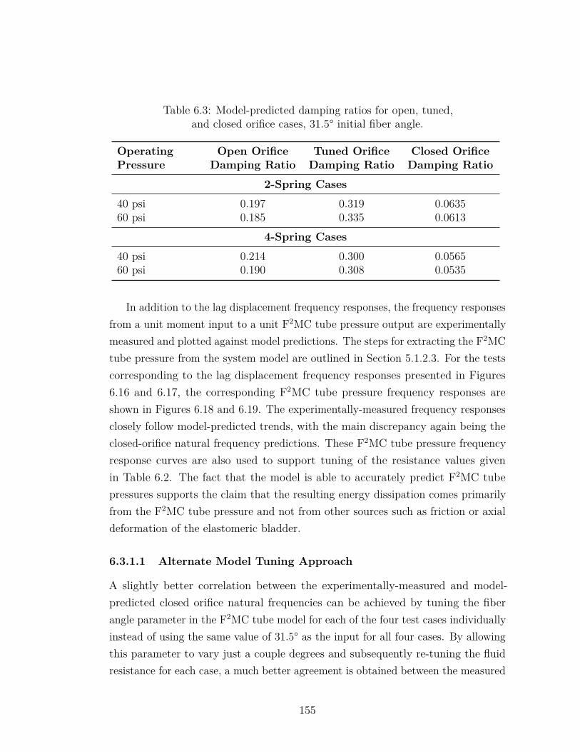
Table 6.3: Model-predicted damping ratios for open, tuned,and closed orifice cases, 31.5° initial fiber angle.
OperatingPressure
Open OrificeDamping Ratio
Tuned OrificeDamping Ratio
Closed OrificeDamping Ratio
2-Spring Cases
40 psi 0.197 0.319 0.063560 psi 0.185 0.335 0.0613
4-Spring Cases
40 psi 0.214 0.300 0.056560 psi 0.190 0.308 0.0535
In addition to the lag displacement frequency responses, the frequency responsesfrom a unit moment input to a unit F2MC tube pressure output are experimentallymeasured and plotted against model predictions. The steps for extracting the F2MCtube pressure from the system model are outlined in Section 5.1.2.3. For the testscorresponding to the lag displacement frequency responses presented in Figures6.16 and 6.17, the corresponding F2MC tube pressure frequency responses areshown in Figures 6.18 and 6.19. The experimentally-measured frequency responsesclosely follow model-predicted trends, with the main discrepancy again being theclosed-orifice natural frequency predictions. These F2MC tube pressure frequencyresponse curves are also used to support tuning of the resistance values givenin Table 6.2. The fact that the model is able to accurately predict F2MC tubepressures supports the claim that the resulting energy dissipation comes primarilyfrom the F2MC tube pressure and not from other sources such as friction or axialdeformation of the elastomeric bladder.
6.3.1.1 Alternate Model Tuning Approach
A slightly better correlation between the experimentally-measured and model-predicted closed orifice natural frequencies can be achieved by tuning the fiberangle parameter in the F2MC tube model for each of the four test cases individuallyinstead of using the same value of 31.5° as the input for all four cases. By allowingthis parameter to vary just a couple degrees and subsequently re-tuning the fluidresistance for each case, a much better agreement is obtained between the measured
155
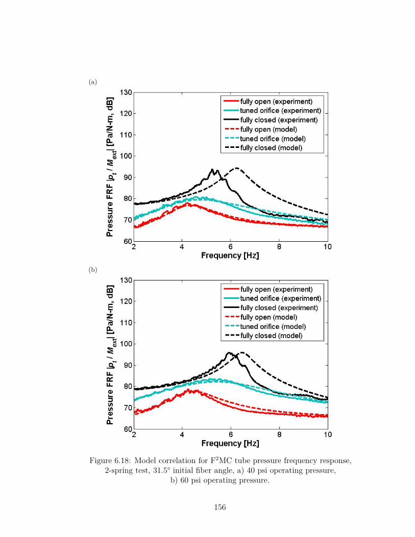
(a)
(b)
Figure 6.18: Model correlation for F2MC tube pressure frequency response,2-spring test, 31.5° initial fiber angle, a) 40 psi operating pressure,
b) 60 psi operating pressure.
156
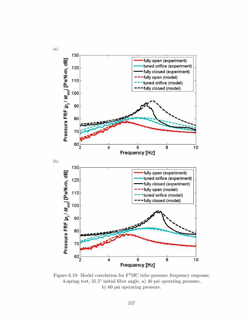
(a)
(b)
Figure 6.19: Model correlation for F2MC tube pressure frequency response,4-spring test, 31.5° initial fiber angle, a) 40 psi operating pressure,
b) 60 psi operating pressure.
157
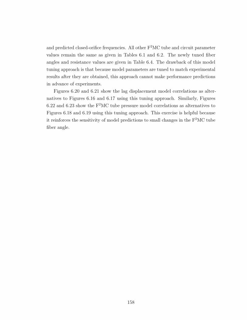
and predicted closed-orifice frequencies. All other F2MC tube and circuit parametervalues remain the same as given in Tables 6.1 and 6.2. The newly tuned fiberangles and resistance values are given in Table 6.4. The drawback of this modeltuning approach is that because model parameters are tuned to match experimentalresults after they are obtained, this approach cannot make performance predictionsin advance of experiments.
Figures 6.20 and 6.21 show the lag displacement model correlations as alter-natives to Figures 6.16 and 6.17 using this tuning approach. Similarly, Figures6.22 and 6.23 show the F2MC tube pressure model correlations as alternatives toFigures 6.18 and 6.19 using this tuning approach. This exercise is helpful becauseit reinforces the sensitivity of model predictions to small changes in the F2MC tubefiber angle.
158
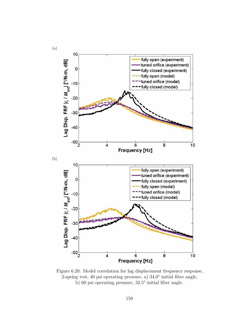
(a)
(b)
Figure 6.20: Model correlation for lag displacement frequency response,2-spring test, 40 psi operating pressure, a) 34.0° initial fiber angle,
b) 60 psi operating pressure, 32.5° initial fiber angle.
159
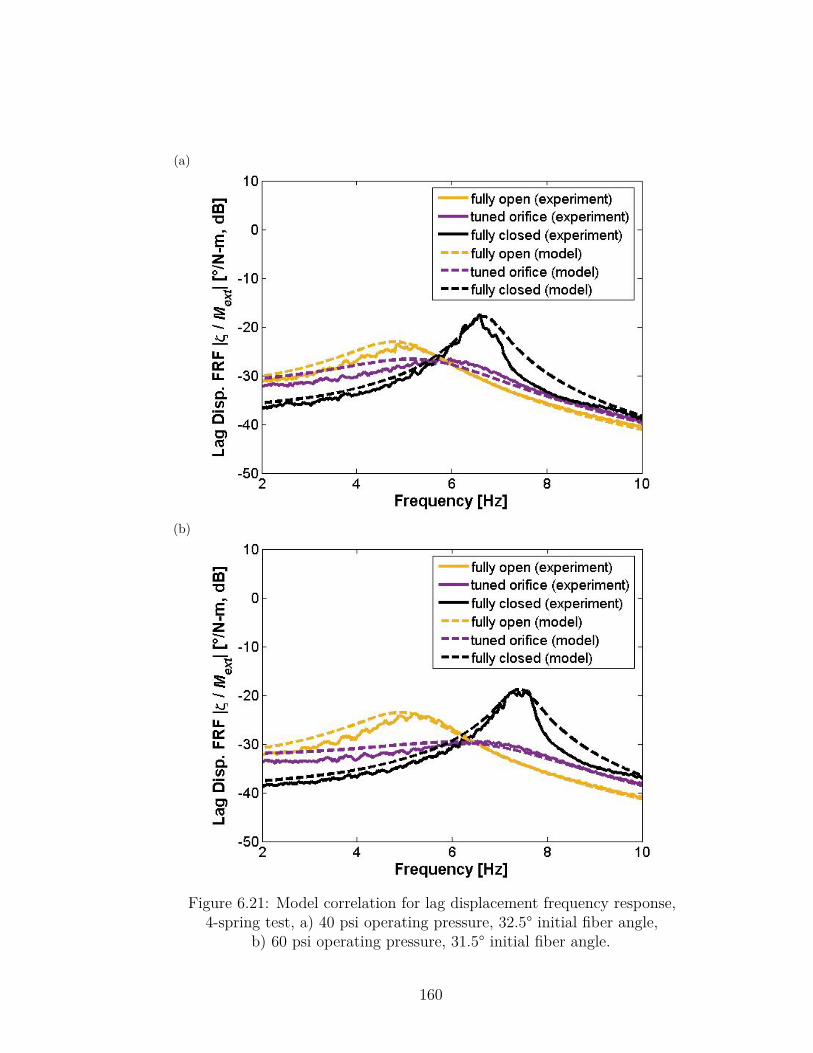
(a)
(b)
Figure 6.21: Model correlation for lag displacement frequency response,4-spring test, a) 40 psi operating pressure, 32.5° initial fiber angle,
b) 60 psi operating pressure, 31.5° initial fiber angle.
160
(a)
(b)
Figure 6.22: Model correlation for F2MC tube pressure frequency response,2-spring test, 40 psi operating pressure, a) 34.0° initial fiber angle,
b) 60 psi operating pressure, 32.5° initial fiber angle.
161
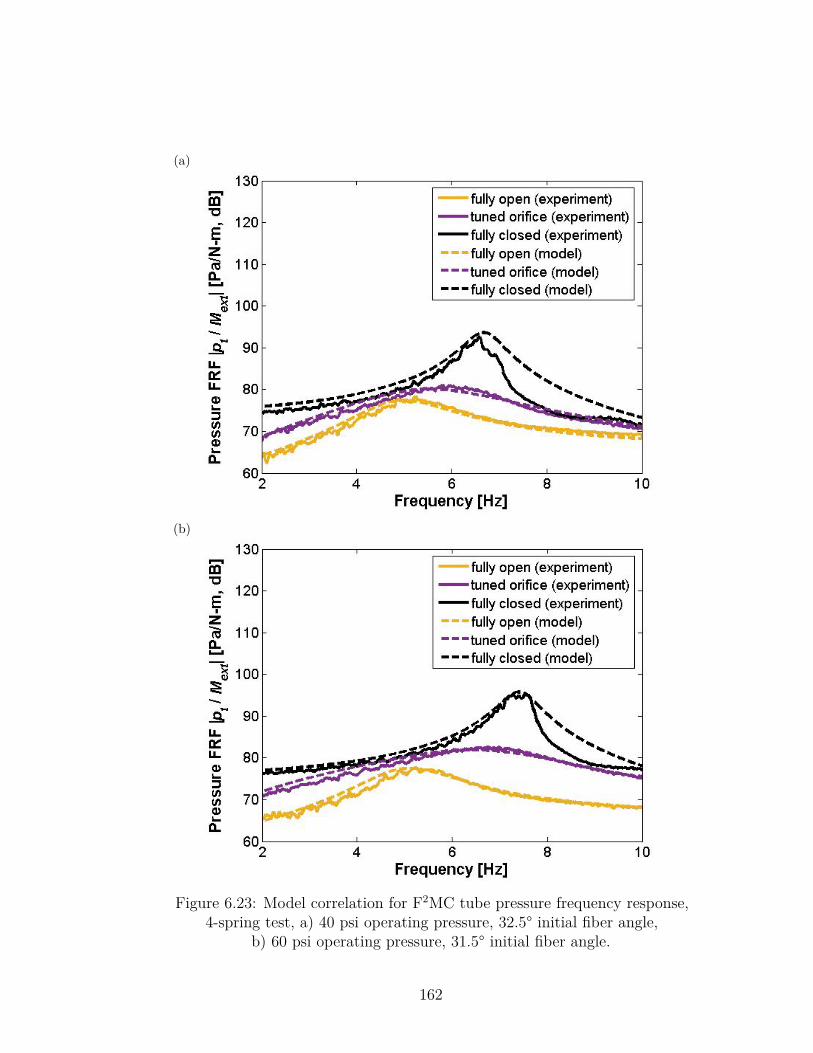
(a)
(b)
Figure 6.23: Model correlation for F2MC tube pressure frequency response,4-spring test, a) 40 psi operating pressure, 32.5° initial fiber angle,
b) 60 psi operating pressure, 31.5° initial fiber angle.
162
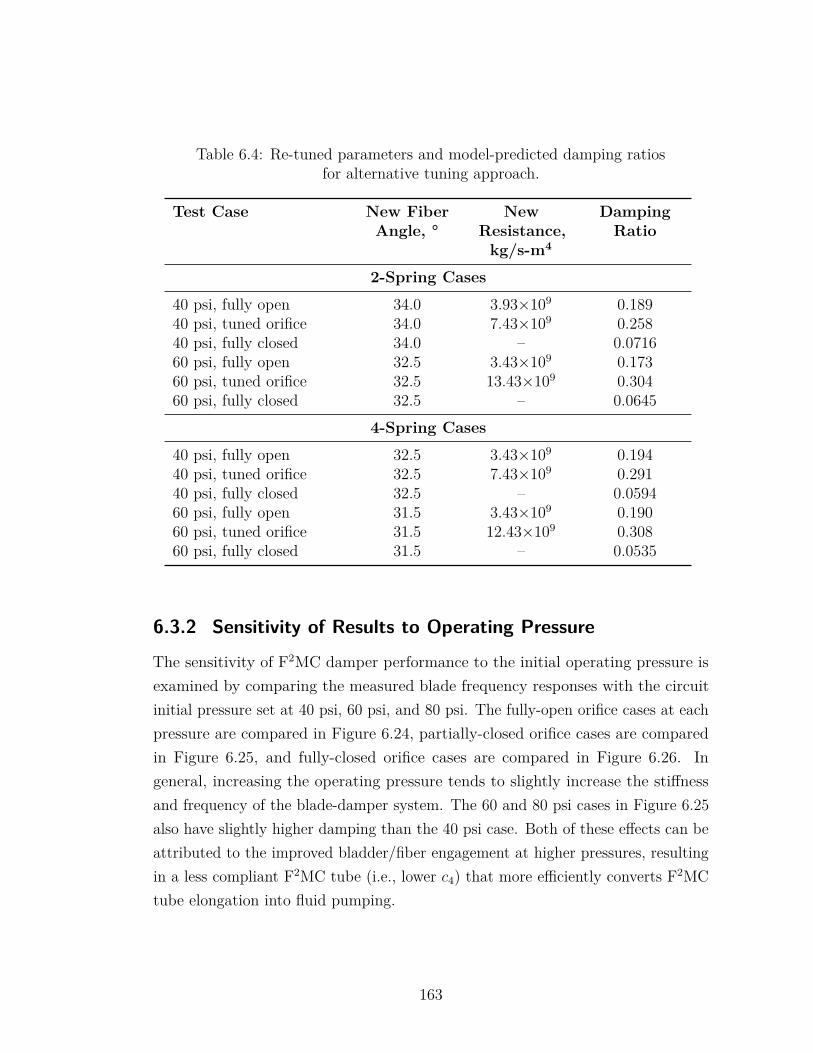
Table 6.4: Re-tuned parameters and model-predicted damping ratiosfor alternative tuning approach.
Test Case New FiberAngle, °
NewResistance,kg/s-m4
DampingRatio
2-Spring Cases
40 psi, fully open 34.0 3.93×10⁹ 0.18940 psi, tuned orifice 34.0 7.43×10⁹ 0.25840 psi, fully closed 34.0 – 0.071660 psi, fully open 32.5 3.43×10⁹ 0.17360 psi, tuned orifice 32.5 13.43×10⁹ 0.30460 psi, fully closed 32.5 – 0.0645
4-Spring Cases
40 psi, fully open 32.5 3.43×10⁹ 0.19440 psi, tuned orifice 32.5 7.43×10⁹ 0.29140 psi, fully closed 32.5 – 0.059460 psi, fully open 31.5 3.43×10⁹ 0.19060 psi, tuned orifice 31.5 12.43×10⁹ 0.30860 psi, fully closed 31.5 – 0.0535
6.3.2 Sensitivity of Results to Operating Pressure
The sensitivity of F2MC damper performance to the initial operating pressure isexamined by comparing the measured blade frequency responses with the circuitinitial pressure set at 40 psi, 60 psi, and 80 psi. The fully-open orifice cases at eachpressure are compared in Figure 6.24, partially-closed orifice cases are comparedin Figure 6.25, and fully-closed orifice cases are compared in Figure 6.26. Ingeneral, increasing the operating pressure tends to slightly increase the stiffnessand frequency of the blade-damper system. The 60 and 80 psi cases in Figure 6.25also have slightly higher damping than the 40 psi case. Both of these effects can beattributed to the improved bladder/fiber engagement at higher pressures, resultingin a less compliant F2MC tube (i.e., lower c4) that more efficiently converts F2MCtube elongation into fluid pumping.
163
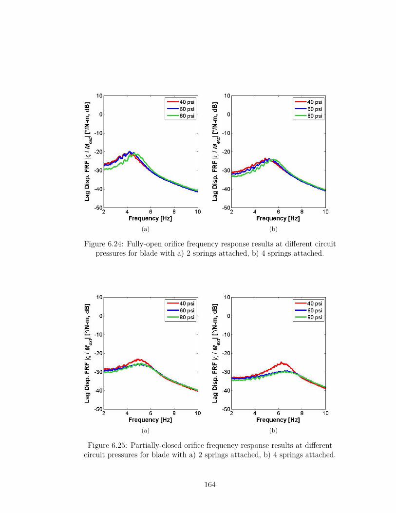
(a) (b)
Figure 6.24: Fully-open orifice frequency response results at different circuitpressures for blade with a) 2 springs attached, b) 4 springs attached.
(a) (b)
Figure 6.25: Partially-closed orifice frequency response results at differentcircuit pressures for blade with a) 2 springs attached, b) 4 springs attached.
164
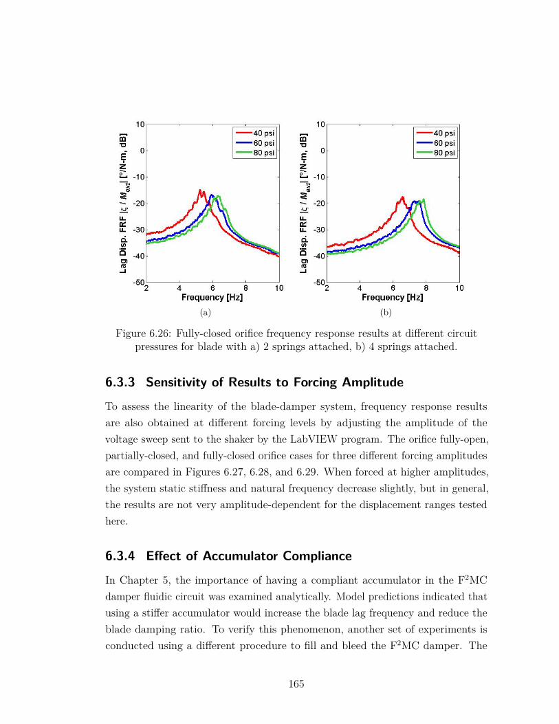
(a) (b)
Figure 6.26: Fully-closed orifice frequency response results at different circuitpressures for blade with a) 2 springs attached, b) 4 springs attached.
6.3.3 Sensitivity of Results to Forcing Amplitude
To assess the linearity of the blade-damper system, frequency response resultsare also obtained at different forcing levels by adjusting the amplitude of thevoltage sweep sent to the shaker by the LabVIEW program. The orifice fully-open,partially-closed, and fully-closed orifice cases for three different forcing amplitudesare compared in Figures 6.27, 6.28, and 6.29. When forced at higher amplitudes,the system static stiffness and natural frequency decrease slightly, but in general,the results are not very amplitude-dependent for the displacement ranges testedhere.
6.3.4 Effect of Accumulator Compliance
In Chapter 5, the importance of having a compliant accumulator in the F2MCdamper fluidic circuit was examined analytically. Model predictions indicated thatusing a stiffer accumulator would increase the blade lag frequency and reduce theblade damping ratio. To verify this phenomenon, another set of experiments isconducted using a different procedure to fill and bleed the F2MC damper. The
165
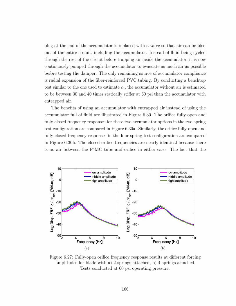
plug at the end of the accumulator is replaced with a valve so that air can be bledout of the entire circuit, including the accumulator. Instead of fluid being cycledthrough the rest of the circuit before trapping air inside the accumulator, it is nowcontinuously pumped through the accumulator to evacuate as much air as possiblebefore testing the damper. The only remaining source of accumulator complianceis radial expansion of the fiber-reinforced PVC tubing. By conducting a benchtoptest similar to the one used to estimate c4, the accumulator without air is estimatedto be between 30 and 40 times statically stiffer at 60 psi than the accumulator withentrapped air.
The benefits of using an accumulator with entrapped air instead of using theaccumulator full of fluid are illustrated in Figure 6.30. The orifice fully-open andfully-closed frequency responses for these two accumulator options in the two-springtest configuration are compared in Figure 6.30a. Similarly, the orifice fully-open andfully-closed frequency responses in the four-spring test configuration are comparedin Figure 6.30b. The closed-orifice frequencies are nearly identical because thereis no air between the F2MC tube and orifice in either case. The fact that the
(a) (b)
Figure 6.27: Fully-open orifice frequency response results at different forcingamplitudes for blade with a) 2 springs attached, b) 4 springs attached.
Tests conducted at 60 psi operating pressure.
166
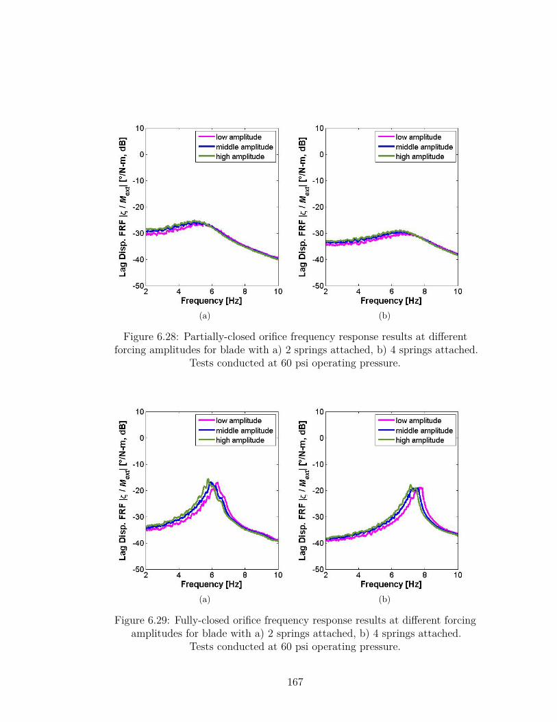
(a) (b)
Figure 6.28: Partially-closed orifice frequency response results at differentforcing amplitudes for blade with a) 2 springs attached, b) 4 springs attached.
Tests conducted at 60 psi operating pressure.
(a) (b)
Figure 6.29: Fully-closed orifice frequency response results at different forcingamplitudes for blade with a) 2 springs attached, b) 4 springs attached.
Tests conducted at 60 psi operating pressure.
167
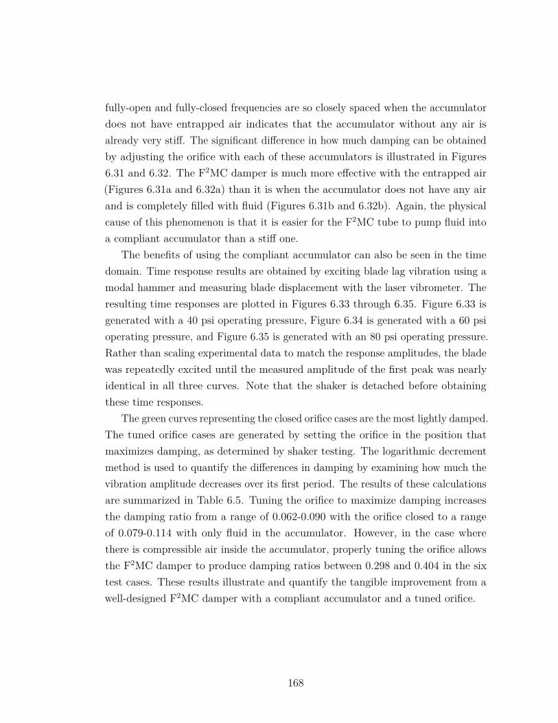
fully-open and fully-closed frequencies are so closely spaced when the accumulatordoes not have entrapped air indicates that the accumulator without any air isalready very stiff. The significant difference in how much damping can be obtainedby adjusting the orifice with each of these accumulators is illustrated in Figures6.31 and 6.32. The F2MC damper is much more effective with the entrapped air(Figures 6.31a and 6.32a) than it is when the accumulator does not have any airand is completely filled with fluid (Figures 6.31b and 6.32b). Again, the physicalcause of this phenomenon is that it is easier for the F2MC tube to pump fluid intoa compliant accumulator than a stiff one.
The benefits of using the compliant accumulator can also be seen in the timedomain. Time response results are obtained by exciting blade lag vibration using amodal hammer and measuring blade displacement with the laser vibrometer. Theresulting time responses are plotted in Figures 6.33 through 6.35. Figure 6.33 isgenerated with a 40 psi operating pressure, Figure 6.34 is generated with a 60 psioperating pressure, and Figure 6.35 is generated with an 80 psi operating pressure.Rather than scaling experimental data to match the response amplitudes, the bladewas repeatedly excited until the measured amplitude of the first peak was nearlyidentical in all three curves. Note that the shaker is detached before obtainingthese time responses.
The green curves representing the closed orifice cases are the most lightly damped.The tuned orifice cases are generated by setting the orifice in the position thatmaximizes damping, as determined by shaker testing. The logarithmic decrementmethod is used to quantify the differences in damping by examining how much thevibration amplitude decreases over its first period. The results of these calculationsare summarized in Table 6.5. Tuning the orifice to maximize damping increasesthe damping ratio from a range of 0.062-0.090 with the orifice closed to a rangeof 0.079-0.114 with only fluid in the accumulator. However, in the case wherethere is compressible air inside the accumulator, properly tuning the orifice allowsthe F2MC damper to produce damping ratios between 0.298 and 0.404 in the sixtest cases. These results illustrate and quantify the tangible improvement from awell-designed F2MC damper with a compliant accumulator and a tuned orifice.
168
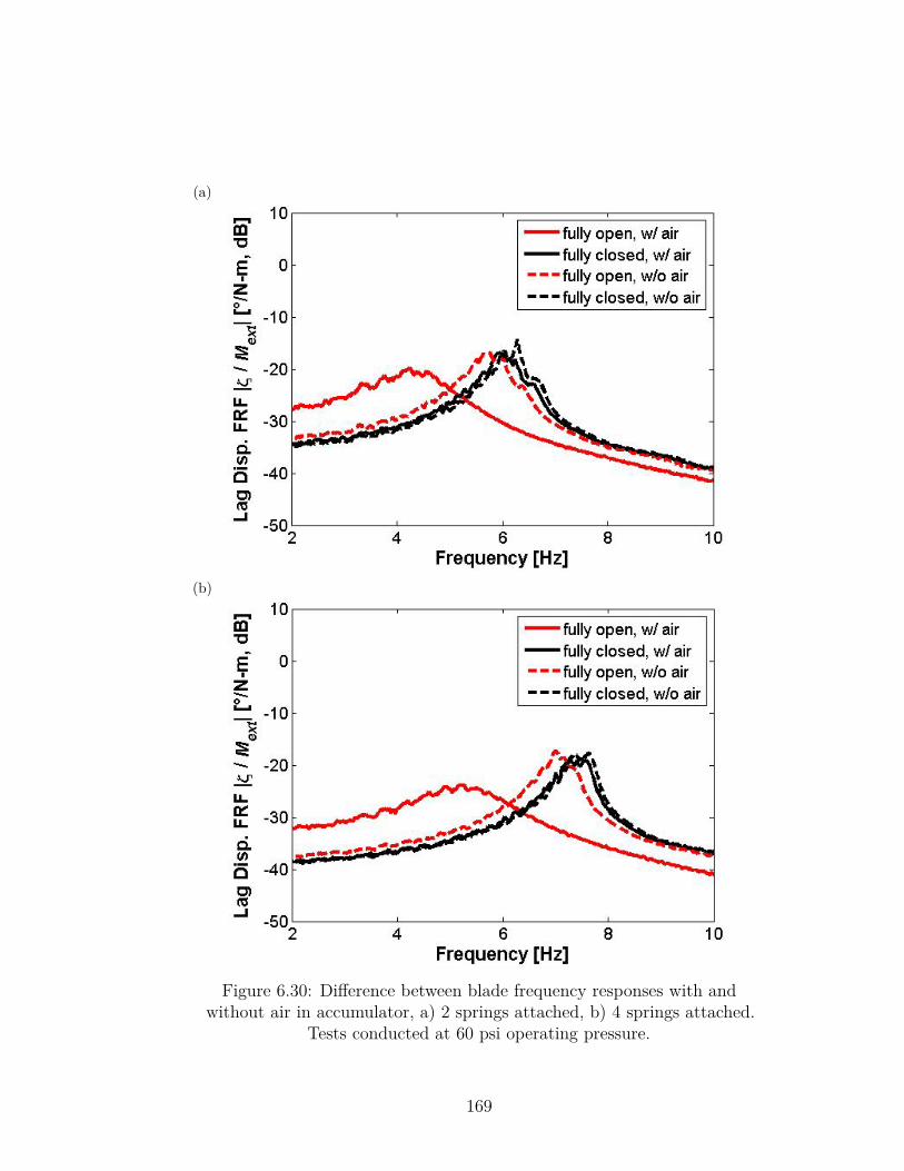
(a)
(b)
Figure 6.30: Difference between blade frequency responses with andwithout air in accumulator, a) 2 springs attached, b) 4 springs attached.
Tests conducted at 60 psi operating pressure.
169
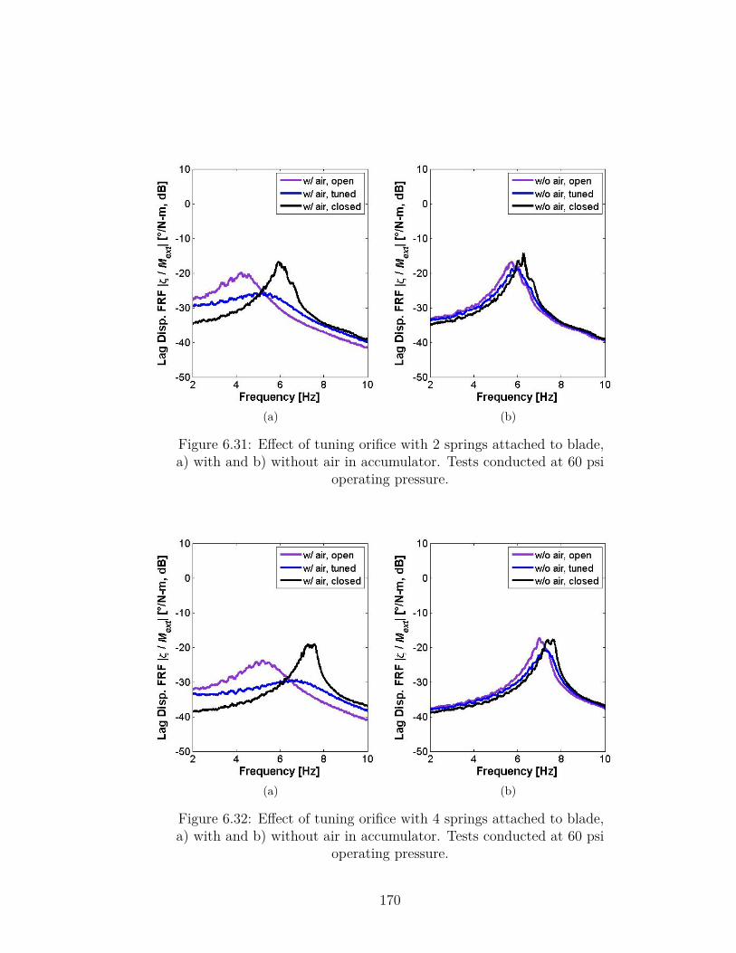
(a) (b)
Figure 6.31: Effect of tuning orifice with 2 springs attached to blade,a) with and b) without air in accumulator. Tests conducted at 60 psi
operating pressure.
(a) (b)
Figure 6.32: Effect of tuning orifice with 4 springs attached to blade,a) with and b) without air in accumulator. Tests conducted at 60 psi
operating pressure.
170
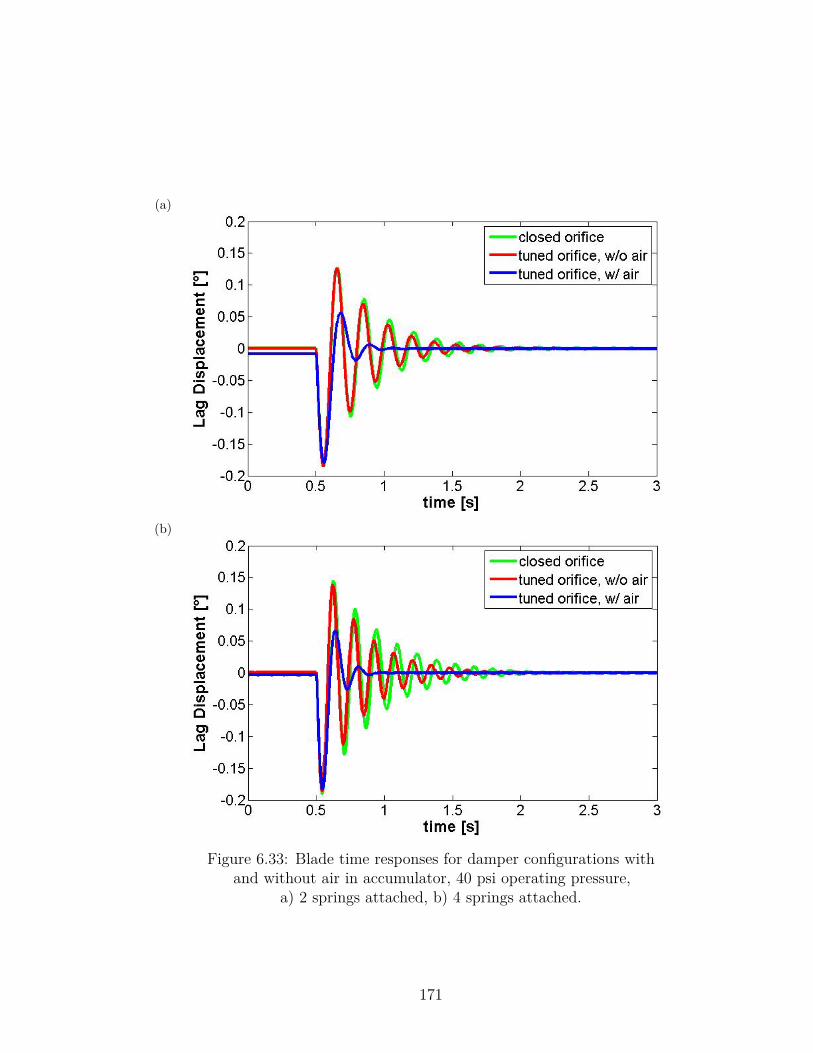
(a)
(b)
Figure 6.33: Blade time responses for damper configurations withand without air in accumulator, 40 psi operating pressure,
a) 2 springs attached, b) 4 springs attached.
171
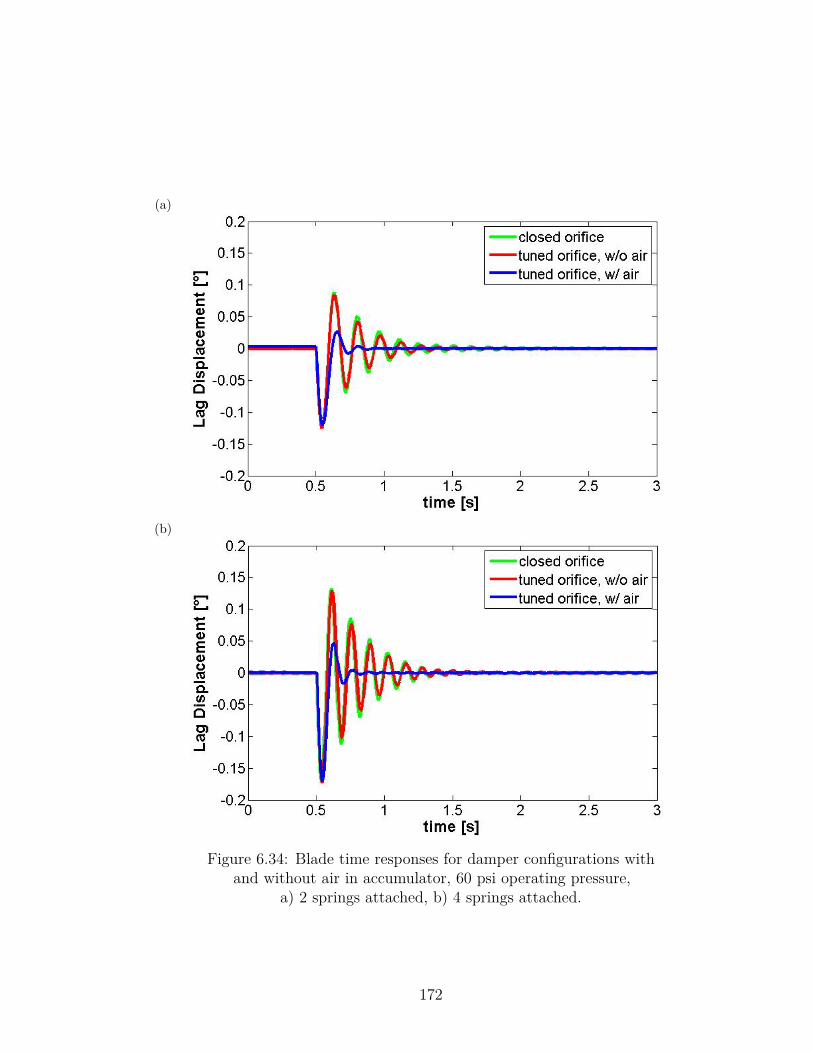
(a)
(b)
Figure 6.34: Blade time responses for damper configurations withand without air in accumulator, 60 psi operating pressure,
a) 2 springs attached, b) 4 springs attached.
172
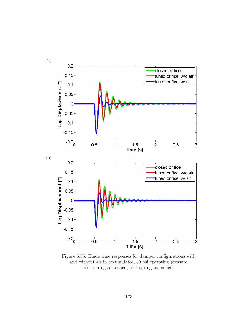
(a)
(b)
Figure 6.35: Blade time responses for damper configurations withand without air in accumulator, 80 psi operating pressure,
a) 2 springs attached, b) 4 springs attached.
173
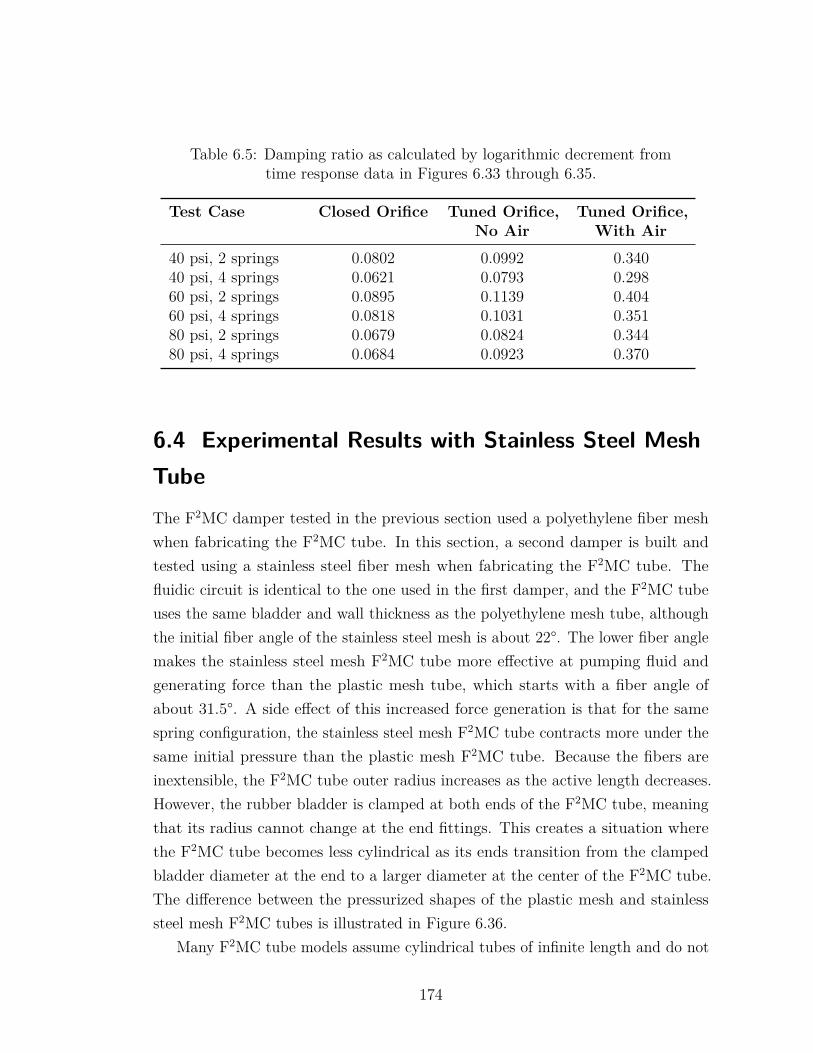
Table 6.5: Damping ratio as calculated by logarithmic decrement fromtime response data in Figures 6.33 through 6.35.
Test Case Closed Orifice Tuned Orifice,No Air
Tuned Orifice,With Air
40 psi, 2 springs 0.0802 0.0992 0.34040 psi, 4 springs 0.0621 0.0793 0.29860 psi, 2 springs 0.0895 0.1139 0.40460 psi, 4 springs 0.0818 0.1031 0.35180 psi, 2 springs 0.0679 0.0824 0.34480 psi, 4 springs 0.0684 0.0923 0.370
6.4 Experimental Results with Stainless Steel MeshTubeThe F2MC damper tested in the previous section used a polyethylene fiber meshwhen fabricating the F2MC tube. In this section, a second damper is built andtested using a stainless steel fiber mesh when fabricating the F2MC tube. Thefluidic circuit is identical to the one used in the first damper, and the F2MC tubeuses the same bladder and wall thickness as the polyethylene mesh tube, althoughthe initial fiber angle of the stainless steel mesh is about 22°. The lower fiber anglemakes the stainless steel mesh F2MC tube more effective at pumping fluid andgenerating force than the plastic mesh tube, which starts with a fiber angle ofabout 31.5°. A side effect of this increased force generation is that for the samespring configuration, the stainless steel mesh F2MC tube contracts more under thesame initial pressure than the plastic mesh F2MC tube. Because the fibers areinextensible, the F2MC tube outer radius increases as the active length decreases.However, the rubber bladder is clamped at both ends of the F2MC tube, meaningthat its radius cannot change at the end fittings. This creates a situation wherethe F2MC tube becomes less cylindrical as its ends transition from the clampedbladder diameter at the end to a larger diameter at the center of the F2MC tube.The difference between the pressurized shapes of the plastic mesh and stainlesssteel mesh F2MC tubes is illustrated in Figure 6.36.
Many F2MC tube models assume cylindrical tubes of infinite length and do not
174
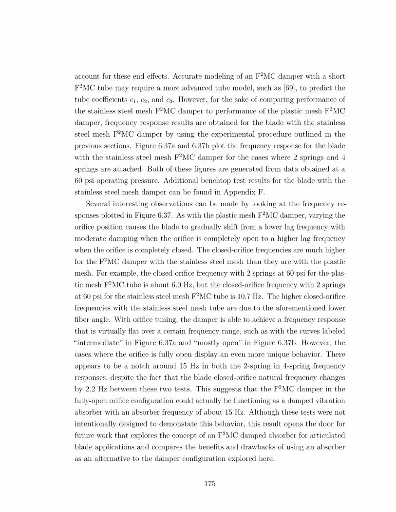
account for these end effects. Accurate modeling of an F2MC damper with a shortF2MC tube may require a more advanced tube model, such as [69], to predict thetube coefficients c1, c2, and c3. However, for the sake of comparing performance ofthe stainless steel mesh F2MC damper to performance of the plastic mesh F2MCdamper, frequency response results are obtained for the blade with the stainlesssteel mesh F2MC damper by using the experimental procedure outlined in theprevious sections. Figure 6.37a and 6.37b plot the frequency response for the bladewith the stainless steel mesh F2MC damper for the cases where 2 springs and 4springs are attached. Both of these figures are generated from data obtained at a60 psi operating pressure. Additional benchtop test results for the blade with thestainless steel mesh damper can be found in Appendix F.
Several interesting observations can be made by looking at the frequency re-sponses plotted in Figure 6.37. As with the plastic mesh F2MC damper, varying theorifice position causes the blade to gradually shift from a lower lag frequency withmoderate damping when the orifice is completely open to a higher lag frequencywhen the orifice is completely closed. The closed-orifice frequencies are much higherfor the F2MC damper with the stainless steel mesh than they are with the plasticmesh. For example, the closed-orifice frequency with 2 springs at 60 psi for the plas-tic mesh F2MC tube is about 6.0 Hz, but the closed-orifice frequency with 2 springsat 60 psi for the stainless steel mesh F2MC tube is 10.7 Hz. The higher closed-orificefrequencies with the stainless steel mesh tube are due to the aforementioned lowerfiber angle. With orifice tuning, the damper is able to achieve a frequency responsethat is virtually flat over a certain frequency range, such as with the curves labeled“intermediate” in Figure 6.37a and “mostly open” in Figure 6.37b. However, thecases where the orifice is fully open display an even more unique behavior. Thereappears to be a notch around 15 Hz in both the 2-spring in 4-spring frequencyresponses, despite the fact that the blade closed-orifice natural frequency changesby 2.2 Hz between these two tests. This suggests that the F2MC damper in thefully-open orifice configuration could actually be functioning as a damped vibrationabsorber with an absorber frequency of about 15 Hz. Although these tests were notintentionally designed to demonstate this behavior, this result opens the door forfuture work that explores the concept of an F2MC damped absorber for articulatedblade applications and compares the benefits and drawbacks of using an absorberas an alternative to the damper configuration explored here.
175
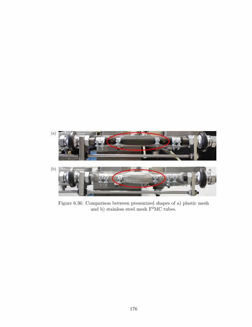
(a)
(b)
Figure 6.36: Comparison between pressurized shapes of a) plastic meshand b) stainless steel mesh F2MC tubes.
176
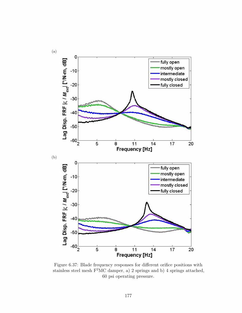
(a)
(b)
Figure 6.37: Blade frequency responses for different orifice positions withstainless steel mesh F2MC damper, a) 2 springs and b) 4 springs attached,
60 psi operating pressure.
177
Chapter 7 |Conclusions and Future Work
Through a combination of analytical modeling and experiments, this researchinvestigates the viability of vibration treatments utilizing F2MC tubes for severaldifferent rotorcraft vibration control applications. The first application focuseson reducing tailboom vibration with a damped F2MC vibration absorber. Alaboratory-scale tailboom is used as a testbed for the design and testing of F2MCvibration absorbers that reduce vibrations in lateral, vertical, and torsional modes.This research is the first use of the finite element method to model a structureintegrated with F2MC tubes, and it is also the first time vibration reduction has beendemonstrated experimentally in a coupled vibration mode using an F2MC absorber.Furthermore, a new absorber configuration that can treat both a vertical and lateralbending tailboom mode with one fludic circuit is demonstrated experimentally. Thisadvances the state-of-the art for F2MC vibration absorbers, which had previouslyonly attempted to control one mode at a time.
The research into the second application of rotor blade damping is the firstattempt to model rotor blades integrated with F2MC tubes for damping of eitherrigid-body lag motion in the case of articulated rotors or in-plane bending motionin the case of hingeless rotors. Initial sizing and parameter studies are performed toassess the effectiveness of these F2MC dampers on full-scale rotor blades. Followingthis analysis, an articulated blade F2MC damper is retrofitted onto a small-scalerotor blade, and its damping performance is successfully demonstrated in benchtoptests. This research is the first integration of an F2MC tube-based damper intorealistic rotor hardware.
178
7.1 Single-Mode & Multi-Mode Tailboom VibrationAbsorberA comprehensive model is developed for a structure integrated with a set of F2MCtubes and a tuned fluidic circuit. The approach couples the dynamics of a three-dimensional finite element structural model and a dynamic model of the F2MCtubes and fluidic circuit. As tailboom bending strains the F2MC tubes, a fluidmass oscillates within the circuit. The effective inertia of this fluid mass is tunedto create a fluidic vibration absorber that reduces vibrations in a target tailboommode. As the fluid oscillates, energy is dissipated due to the fluid viscosity.
A structural model is developed and experimentally verified for a 6 foot longlaboratory-scale tailboom. The structural model uses 22 Euler-Bernoulli beamfinite elements and adequately predicts the tailboom low-frequency dynamics. TheF2MC tube model characterizes the tube force and volume as a function of its axialdisplacement and internal pressure, while the fluidic model captures the inertiatrack dynamics through the lumped parameters of inertance and resistance. Thestructural and fluidic domains are coupled by relating nodal displacements in thefinite element model to the resulting F2MC tube displacements. Equations ofmotion are derived for the full system including tailboom, F2MC tube, and fluiddynamics.
Using the comprehensive system model, two possible configurations for reducingvibrations in a 26.7 Hz lateral bending/torsion tailboom mode are considered.According to model predictions, a damped vibration absorber designed to directlyreduce lateral bending vibrations in this coupled mode will also reduce torsionalvibrations. Conversely, the model predicts that an absorber designed to directlyreduce torsional vibrations in this mode can also reduce lateral bending vibrations.Model results suggest that the absorber designed to directly reduce bending vibra-tions is more effective at treating the target 26.7 Hz mode. The bending absorber isalso more practical from an engineering standpoint because it requires less inertiatrack tubing. The F2MC absorber designed to treat lateral bending vibration usesfour F2MC tubes arranged in two pairs symmetrically about the lateral bendingplane. As the tailboom bends laterally, F2MC tubes on one side extend axially topump fluid, and tubes on the opposite side shorten axially to receive fluid. The
179
lengths of inertia track segments connecting the left and right side F2MC tubepairs are tuned to set the absorber frequency based on the given F2MC tubes andchoice of working fluid.
Parametric studies are conducted to study the effect of changing inertia trackradius and F2MC tube length in the lateral bending absorber. Decreasing inertiatrack radius has the benefit of reducing the inertia track length needed to tune theF2MC absorber, making the absorber more compact. However, a narrower track alsoincreases losses due to fluid viscosity, resulting in a slightly less effective vibrationabsorber. Performance for a range of different track radii varies from 67% to 72%vibration reduction at resonance with proper inertia track tuning. Reducing thelength of the tailboom spanned by the F2MC tubes increases their effective stiffnessas quantified by the capacitance parameter c4. As the F2MC tube is shortened,more inertance is needed to tune the circuit for the same absorber frequency. Themodel predicts that with proper tuning of the fluidic circuit, shortening the F2MCtubes from 25 in. to 15 in. long only reduces the F2MC absorber effectivenessfrom 71% reduction at resonance to 66% reduction, although the tuned inertiatrack main segment length becomes 2.3 times longer if the track radius remainsunchanged.
An F2MC absorber is built and tested on the laboratory-scale tailboom to verifythe model prediction that bending and torsional vibrations can be reduced withthe same absorber. The absorber uses four F2MC tubes fabricated by pulling astainless steel mesh over a 3/8 in. inner diameter, 1/32 in. thick rubber bladder.Three different fluidic circuits are tested: one with rigid copper tubing and wateras the working fluid, one with rigid copper tubing and a high-density working fluid(specific gravity ≈ 1.88), and one with rigid plastic tubing and water as the workingfluid. Frequency response results are experimentally obtained by measuring theinput force from a shaker and output displacements at the tailboom tip and on thehorizontal and vertical tails. Reductions of up to 80% in both bending and torsionalvibration are demonstrated in the coupled 26.7 Hz lateral bending/torsion tailboommode. Good correlation is observed between model-predicted and experimentally-measured frequency responses with the F2MC absorber. The model also predictsthat the tailboom vibration reduction is accompanied by a reduction in the internalshear force and moment.
180
Although the absorber performs similarly with all three fluidic circuits, eachof them have unique advantages. The circuit with rigid copper tubing and waterachieves slightly better vibration reduction than the circuit with the high-densityfluid, although the tuned inertia track in the latter absorber is shorter and morecompact because of the higher fluid density. Substituting lightweight plastic tubingfor the copper tubing does not significantly degrade the absorber performance; themaximum vibration reduction observed at resonance is 80% with the copper tubingand 77% with the plastic tubing.
After successfully demonstrating a tailboom F2MC vibration absorber thatcontrols a single coupled lateral bending/torsion mode, its fluidic circuit design isslightly modified to treat one lateral bending and one vertical bending mode withthe same circuit. This multi-mode concept is evaluated on the tailboom by testing afluidic circuit designed to reduce vibration in a 12.2 Hz vertical bending mode and a26.7 Hz lateral bending/torsion mode. The circuit is tuned in two steps. First, thebranch length that optimally tunes the fluidic circuit for the 26.7 Hz lateral/bendingtorsion mode is identified. Next, the length of the segment connecting the toppair of F2MC tubes to the bottom pair of F2MC tubes is adjusted until the circuitis tuned for the 12.2 Hz vertical mode as well. The tuned multi-mode absorberreduces vibration by 63% and 65% in the vertical and lateral modes, respectively,whereas the absorber tuned only for a vertical mode reduces vibration by 68% inthe vertical mode but just 42% in the lateral bending/torsion mode. Tuning thecircuit to reduce vibrations in both the 26.7 Hz lateral bending/torsion mode andthe 12.2 Hz vertical bending mode increases the overall absorber weight by lessthan 2%, since an inertia track with rigid plastic tubing only makes up a smallfraction of the overall absorber weight.
7.2 Rotor Blade DampersTwo different concepts are introduced for damping rotor blade in-plane motionwith F2MC tubes. The first concept is intended for use on articulated rotors. Thepiston in a conventional hydraulic lead-lag damper is replaced with an F2MC tube,and energy is dissipated by pumping fluid through an orifice. The second conceptis intended for use on hingeless rotors. The hingeless blade concept functions as adamped vibration absorber, harnessing blade chordwise bending strain to pump
181
fluid through a tuned inertia track and into an accumulator. Models that coupleblade dynamics with F2MC tube and fluid dynamics are derived for both concepts.
The feasibility of each concept is assessed by modeling a representative bladewith the corresponding F2MC damper. An articulated blade based on the UH-60rotor is modeled and integrated with an F2MC damper, and parametric studies areperformed to understand the effect of varying orifice resistance and accumulatorcapacitance. As the blade lag angle increases, the F2MC tube shortens, and thefiber angle α increases. This reduces the amount of fluid pumped by the F2MCtube, since it is most effective at pumping fluid when the fiber angle is low. Up toa certain point, increasing orifice resistance results in an increased blade dampingratio for the linearized blade-damper system, although this also results in higherF2MC tube oscillatory pressures. Increasing accumulator capacitance results inincreased blade damping and reduced F2MC damper stiffness.
A stiff-inplane hingeless blade based on the X2 rotor is used as a baseline toevaluate the F2MC damped absorber concept for stiff-inplane hingeless rotor blades.The rotating blade is modeled using 12 Euler-Bernoulli beam finite elements withchordwise bending degrees of freedom. In the dampers analyzed by this research,the F2MC tube is installed either inside the blade spar or outside the blade leadingedge. Eigenvalue analysis predicts that first chordwise bending mode (frequency= 1.4/rev) damping ratio can be increased from a baseline of 0.02 to a rangeof 0.059-0.066 by integrating an F2MC absorber into the blade root, with theF2MC tube spanning 10% of the blade radius. Choosing an accumulator with highcapacitance makes the absorber more effective and can reduce the correspondinginertia track length needed to tune the absorber.
Soft-inplane hingeless rotors represent an intermediate configuration betweenarticulated and stiff-inplane rotors. A soft-inplane blade (frequency = 0.66/rev)based on the BO105 rotor is analyzed using the same finite element approach, andboth the F2MC damper and the F2MC damped absorber circuit configurations areevaluated. Based on model results, both circuits are feasible options for augmentingthe damping of soft-inplane rotors. The effectiveness of either the F2MC damperor the F2MC damped absorber depends on the flexure stiffness and the blade modeshape. Making the flexure softer relative to the rest of the blade changes the blademode shape to localize more strain at the blade root where the F2MC tube isattached, thereby making the damper more effective.
182
To experimentally demonstrate the articulated blade F2MC damper concept,a damper consisting of an F2MC tube, an inertia track, a tunable orifice, and anaccumulator is integrated into a small-scale blade that is free to pivot about a laghinge. The prototype damper uses a combination of spherical and linear bearings toconstrain the F2MC tube to axial motion as the blade leads and lags. A compliantaccumulator is realized by entrapping compressible air inside the accumulator afterbleeding air from the rest of the fluidic circuit.
The damper is tested on the benchtop by using springs to simulate the centrifugalstiffness at a given rotor speed. In general, good correlation is observed betweenmodel predictions and experimentally-measured frequency responses. Based onmodel predictions, the blade damping ratios in these frequency-domain benchtoptests increase from a range of 0.054-0.064 with the orifice fully closed to a range of0.300-0.335 with the orifice tuned to maximize damping. Benchtop tests also verifythe importance of having a compliant accumulator. Experimental results showthat a damper tested with the accumulator completely full of fluid is much lesseffective than one containing compressible air. In time-domain results, measuredblade damping ratios are in the range of
• 0.062-0.090 with the orifice fully closed,• 0.079-0.114 using an accumulator filled with fluid and no air, and• 0.298-0.404 using an accumulator with entrapped air.
7.3 Recommendations for Future WorkThis section briefly describes some suggestions for future work that would build uponthis research and further mature F2MC tubes as a technology. These suggestionsare broken down into two main categories: research that would be valuable forgeneral vibration control applications with F2MC tubes, and research focused onthe rotor blade damping applications introduced in Chapters 5 and 6.
7.3.1 General F2MC Tube Research
The ability to predict the F2MC tube capacitance parameter c4 in advance wouldgreatly improve the accuracy of early inertia track tuning and the prediction ofF2MC treatment performance. In an F2MC vibration absorber, the parameter c4
183
determines the effective absorber stiffness. It is important to quantify this parameterso that the model accurately predicts the inertia track length and/or radius that willyield a desired absorber frequency. However, this research frequently approximatedthe c4 parameter based on previous empirical measurements, and the validity ofthese approximations have not yet been confirmed. The linearized model [68] inthis research only calculates F2MC tube coefficients c1-c3. Both analytical andexperimental research could be done to improve the fidelity of c4 approximationsfor new F2MC tubes, rather than relying on benchtop experiments to determine c4
after an F2MC tube has already been sized and fabricated. Finite element analysiscould be used to model a bladder reinforced by a fiber mesh and compute the F2MCtube volume change due to an applied internal pressure. Alternatively, benchtopexperiments could be conducted to characterize the capacitance of F2MC tubeshaving different lengths, diameters, and bladder thicknesses to build correlationsbetween F2MC tube parameters and empirically measured c4 values.
Another topic for further F2MC tube research could be more detailed design todevelop “production-ready” end fittings and assess the static and fatigue strength ofF2MC tubes built using realistic hardware. Off-the-shelf components such as barbedfittings and hose clamps were used for ease of fabrication in this research. However,designing custom hardware would likely result in a more reliable F2MC tube andmay also reduce the weight and/or size of end fittings. For example, Woods et al. [90]used finite element analysis to support the design of end fittings for pneumaticartificial muscles (PAMs), and this specialized end fitting was demonstrated to lastover 120,000,000 pressurization cycles. Static testing was also conducted, with bothends of the actuator fixed and internal pressure applied. The observed failure modein all three specimens was rupture of the polyethylene mesh at an applied pressureof about 270 psi, and the authors note that the polyethylene mesh limited theactuator static strength rather than the bladder. Follow-up research could evaluatewhether using different mesh or bladder materials improves the actuator strength.
Woods et al. [90] mentions several failure modes noted by other researchersincluding the fiber mesh pulling out of the clamps, pinhole leaks in the bladder,and bladder rupture. Placing emphasis on studying and improving F2MC tubedurability could identify which failure modes are most likely to occur and revealvaluable information about the practical limitations of F2MC tubes. As Chapters 5and 6 illustrated, the models presented in this research can be used to estimate the
184
pressures that an F2MC tube will develop at a given vibration level. If informationabout the typical vibratory loading for a structure is known ahead of time, thenthe F2MC tube in a given treatment can be sized to reduce vibrations by a desiredamount and also to ensure that it will have an adequate fatigue life and/or safetyfactor for the application.
7.3.2 Blade Damper Research
Because this is the first research to consider the idea of an F2MC rotor bladedamper, there are many paths for future work on this subject. Improvements canbe made to both the damper models presented in Chapter 5 and the hardwaredesigned in Chapter 6.
7.3.2.1 Articulated Blade and Damper Modeling
The articulated blade model presented in this research is very simple. The modeltreats the blade as a rigid body and only considers the lead-lag degree of freedom,neglecting both flap and pitch motions and eliminating any effects of couplingbetween different blade modes. While this research recognizes that the blade lagangle significantly affects the F2MC damper behavior, it does not attempt topredict what the steady blade lag angle will be in different flight conditions suchas hover, forward flight, or maneuvers. Both the aerodynamic forcing as well asdamper design parameters such as the F2MC tube diameter, active length, initialpressurization, and moment arm about the lag hinge will affect the equilibrium lagangle, which can be calculating by balancing moments about the lag hinge. Thismoment balance should consider the fact that as the rotor spins up, the circuitpressure will gradually increase from its pressure when the rotor is at rest. Asthe blade straightens out due to the centrifugal restoring moment, the F2MC tubestretches axially, decreases in volume, and pushes fluid into the accumulator tocompress the gas until equilibrium is reached. Because this changing pressure duringrotor spin-up will continuously change the moment exerted by the F2MC tube onthe blade, an iterative solution may be necessary to determine the equilibrium lagangle and circuit pressure.
While the linearized model presented in Chapter 5 suggested the initial feasibilityof the F2MC damper, several simplifications were made to maintain linearity of
185
the fluidic circuit model. As Chapter 5 mentioned, the blade lead-lag motioncauses the F2MC tube to undergo large axial displacements and exhibit nonlinearbehavior as the fiber wind angle changes. A fully nonlinear F2MC tube model thatis able to continuously predict the F2MC tube state, including the tube volumeand force exerted on the blade for a given displacement and pressure, would allowfor more refined simulation of the blade-damper system. In addition, modelingend effects due to the nonuniform F2MC tube diameter illustrated in Figure 6.36may improve predictions and reveal information about how the F2MC behaviordiffers from the linear model predictions as the end effects become more significant.Theoretically, the end effects would become more significant for shorter F2MCtubes and at higher contraction ratios. Some nonlinear McKibben actuator modelshave included geometric end effects [64, 69, 91]; however, these models typicallyfocus on the relationship between input pressure and the resulting tube length withan applied axial load. For a nonlinear F2MC tube model, the tube internal volumeis also of interest, since that dictates how much fluid is pumped by the F2MC tubeas it changes length. End effects are much less of a concern for the hingeless rotorblade and tailboom applications, since the F2MC tube length does not change assignificantly as it does in the articulated blade damper.
Modeling the damper orifice as a linear fluid resistance is another approximationfrom this research which keeps the system dynamics linear, although it is notphysically precise. Eq. (5.4) could have been modified to incorporate the nonlinearrelationship [92]
Q = AorfCd
√2(pt − pa)
ρ
(pt − pa)|pt − pa|
, (7.1)
where Aorf is the orifice cross-sectional area and Cd is the orifice discharge coefficient.This equation captures the so-called “V-squared” resistance of a hydraulic orificeand could more accurately predict the complex pressures and forces generated overan F2MC damper cycle. The orifice cross-sectional area is also more useful as adesign variable than orifice resistance Rc, since the area has physical significancewhereas orifice resistance was effectively a tuning parameter in this research.
Finally, although the articulated blade damper concept with one F2MC tube, anorifice, and an accumulator was successfully demonstrated in benchtop tests, this isnot guaranteed to be the most effective way to implement an F2MC damper on an
186
articulated rotor blade. It may be worthwhile to conceptualize, analyze, and testother F2MC damper configurations in future research. For example, one alternatedamper configuration could attach a second F2MC tube on the leading-edge sideof the blade so that fluid is pumped between an antagonistic pair of F2MC tubesinstead of one F2MC tube and an accumulator.
7.3.2.2 Articulated Blade Damper Hardware & Circuit
One of the main reasons for building the benchtop F2MC damper prototype inChapter 6 was to start understanding the practical challenges of implementing thisconcept. Early testing revealed that without any mechanism for aligning the twoend fittings, the F2MC tube would bend out-of-plane due to the weight of its endfittings and the attached valves or pressure transducers. The spherical bearingsallow the end fittings to rotate, and the F2MC tube has very low bending stiffness,especially if the tube is not under significant tension. The problem was addressedadequately in this research by adding a linear bearing and a guide rod as illustratedin Figure 6.12. However, because the linear bearing can accomodate some guiderod misalignment, it is possible for the F2MC tube to twist slightly between thetwo end fittings. To prevent this, the hardware could have been redesigned so thattwo guide rods are used for each F2MC tube as shown in Figure 7.1. With this newdesign, the entire F2MC tube is still free to spin around its own axis, but the twoends would not be able to twist relative to each other. The alignment mechanismused in this damper prototype was conveniently designed and implemented usingoff-the-shelf hardware, but there may be better ways to constrain the F2MC tubein the damper to purely axial motion.
The experiments in Chapter 6 confirmed the importance of using a soft accu-mulator to achieve an F2MC damper with low stiffness and high damping. In thebenchtop experiment, this is accomplished by trapping air behind the orifice inthe circuit. For the best possible damper performance, all of the compressibilityin the circuit should remain behind the orifice. If any air were to remain stuck inthe F2MC tube or the inertia track, this would lower the effective bulk modulus ofthe hydraulic oil and reduce the amount of fluid pumped through the orifice. In arotating environment, the air may have a different equilibrium position within thefluidic circuit. Movement of this entrapped air could cause the damper to performdifferently when rotating than it does in benchtop tests, especially if air travels past
187
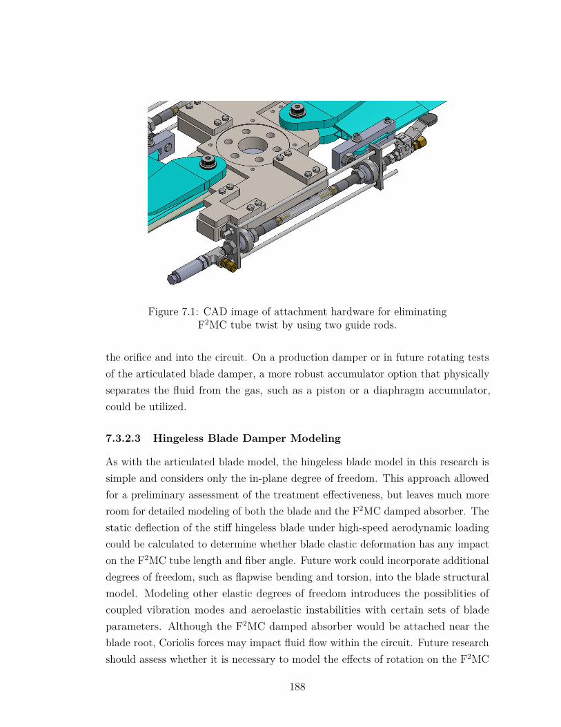
Figure 7.1: CAD image of attachment hardware for eliminatingF2MC tube twist by using two guide rods.
the orifice and into the circuit. On a production damper or in future rotating testsof the articulated blade damper, a more robust accumulator option that physicallyseparates the fluid from the gas, such as a piston or a diaphragm accumulator,could be utilized.
7.3.2.3 Hingeless Blade Damper Modeling
As with the articulated blade model, the hingeless blade model in this research issimple and considers only the in-plane degree of freedom. This approach allowedfor a preliminary assessment of the treatment effectiveness, but leaves much moreroom for detailed modeling of both the blade and the F2MC damped absorber. Thestatic deflection of the stiff hingeless blade under high-speed aerodynamic loadingcould be calculated to determine whether blade elastic deformation has any impacton the F2MC tube length and fiber angle. Future work could incorporate additionaldegrees of freedom, such as flapwise bending and torsion, into the blade structuralmodel. Modeling other elastic degrees of freedom introduces the possiblities ofcoupled vibration modes and aeroelastic instabilities with certain sets of bladeparameters. Although the F2MC damped absorber would be attached near theblade root, Coriolis forces may impact fluid flow within the circuit. Future researchshould assess whether it is necessary to model the effects of rotation on the F2MC
188
absorber, and it should also determine under which conditions or with which choicesof circuit design parameters these effects become significant. The use of F2MCdamped absorbers to stabilize an unstable rotor or to further improve the stabilitymargin of a stable rotor could be another area of future research.
If a passive device cannot provide sufficient blade damping, or if the chordwisebending frequency is sensitive to rotor speed and a more robust device is neededto provide damping across a wider frequency range, then an active F2MC damperusing hydraulic power may also be considered as a potential damping solution.
7.3.2.4 Testing of Articulated & Hingeless Blade Dampers inRotating Environment
The eventual goal of this F2MC damper research is to successfully demonstrateincreased damping for both articulated and hingeless rotor blades in a rotatingframe. For a number of reasons, this is much more complicated than demonstratingdamper performance on a benchtop test. Some factors to consider when planningand conducting these tests include:
• Instrumentation: A displacement sensor for each rotor blade must beintegrated into the hub. For the articulated blade application, these sensorsmust be capable of sensing low frequency (0-10 Hz) vibration, and they mustalso have suitable sensitivity and measurement range to observe blade lagdisplacement in the rotating frame. Having at least one pressure transducerin the fluidic circuit would be useful for real-time pressure monitoring. Asmentioned earlier, spinning up the rotor from rest will cause the pressure inthe fluidic circuit to increase as the blade straightens out. This testing wouldbe complemented well by an analytical prediction of final rotating F2MC tubepressure as part of the moment balance discussed in Section 7.3.2.1. Thisprediction could be verified by the experiment and could also help determinethe initial pressurization that results in the desired circuit pressure when therotor is at full speed. High-speed cameras can be used to visualize the F2MCdamper as it is rotating and aid in troubleshooting any issues that arise.
• Signal Conditioning: Conducting tests in a rotating frame requires signalsto be passed back into the fixed frame through a slip ring, which may resultin increased noise that disrupts sensor measurements. Signal processing
189
methods such as digital filtering may be necessary to separate unwantedsignal components, such as 1/rev and other steady-state harmonic vibration,from the transient blade motion that more clearly illustrates damping. Whenpossible, low-noise sensors that are not affected by the expected centrifugalaccelerations should be selected for these tests.
• Excitation: To prove that the F2MC damper is effective in a rotatingenvironment, the blade lag mode must be perturbed sufficiently to measurethe difference between a slowly-decaying baseline vibration case and a casewhere the F2MC damper causes the lag mode to decay faster. The lightly-damped case could either be the baseline rotor blade or the blade with theF2MC damper installed and the orifice fully closed. In helicopter flight testing,rotor aeromechanical stability can be assessed by applying cyclic blade pitchto excite the lag mode and then measuring the resulting decay. However,the hub fabricated for this research was not designed to accomodate bladepitch, and implementing this excitation method in a rotating test wouldbe complex. Exciting the lag mode in a reliable and repeatable mannermay require installation of one or more actuators on the rotor blade, withappropriate actuator control signals passed through the slip ring.
• Rotor Speed Regulation: The benchtop tests in Chapter 6 simulate thecentrifugal stiffness due to a constant rotational speed. If the rotor speedis not constant in the actual test, energy from the blade lag motion may betransferred from the blade into the driveshaft, making it harder to observe alow-damping baseline case. Ideally, the rotor speed can be precisely maintainedby an electronic control system with strong control gains. Adding more massto the rotor hub would also increase the rotor inertia and reduce any rotorspeed fluctuations. Appropriate instrumentation should be added to the rotorsystem to measure its rotation speed in real time and ensure that it remainsconstant as blade lag motion is perturbed.
The Penn State Adverse Environment Rotor Test Stand has been identified asone candidate facility for this research, although other options may be explored ifnecessary.
190
Appendix A|Element Properties inLaboratory-Scale TailboomModel
The table below contains cross-section information for all fourteen tailboom elementsas calculated based on properties in [76]. This cross-section information is used ingenerating element mass and stiffness matrices for the fourteen tailboom elements.Elements are numbered such that element 1 is the one closest to the root andelement 14 is the one closest to the tip. In this research, the tailboom finite elementmesh changes slightly as the tube length varies, since the model requires bothF2MC tube attachment points to be nodes. However, these changes in the meshhave minimal effect on the predicted tailboom natural frequencies and mode shapes.Point masses and root spring values also change slightly for different models asdiscussed in the text. Tuning these values helps match certain tailboom naturalfrequencies more closely to experimental results depending on which ones are mostimportant for the research at hand.
The cross-sectional area moment values in this table are before stiffness modifi-cations made for model tuning purposes. Specifically, the second area moments Iyyand Izz in the model are reduced by 25% from the values listed in Table A.1 whencalculating the element stiffness matrix.
191
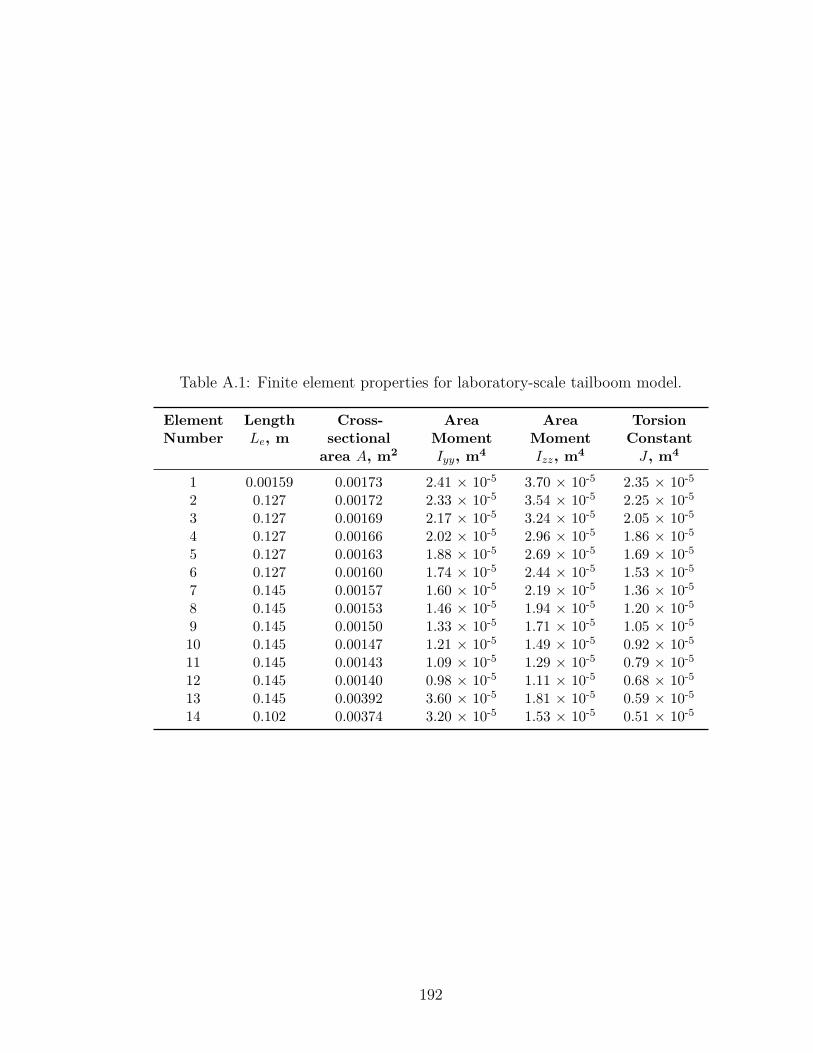
Table A.1: Finite element properties for laboratory-scale tailboom model.
ElementNumber
LengthLe, m
Cross-sectional
area A, m2
AreaMomentIyy, m4
AreaMomentIzz, m4
TorsionConstantJ , m4
1 0.00159 0.00173 2.41 × 10⁻⁵ 3.70 × 10⁻⁵ 2.35 × 10⁻⁵
2 0.127 0.00172 2.33 × 10⁻⁵ 3.54 × 10⁻⁵ 2.25 × 10⁻⁵
3 0.127 0.00169 2.17 × 10⁻⁵ 3.24 × 10⁻⁵ 2.05 × 10⁻⁵
4 0.127 0.00166 2.02 × 10⁻⁵ 2.96 × 10⁻⁵ 1.86 × 10⁻⁵
5 0.127 0.00163 1.88 × 10⁻⁵ 2.69 × 10⁻⁵ 1.69 × 10⁻⁵
6 0.127 0.00160 1.74 × 10⁻⁵ 2.44 × 10⁻⁵ 1.53 × 10⁻⁵
7 0.145 0.00157 1.60 × 10⁻⁵ 2.19 × 10⁻⁵ 1.36 × 10⁻⁵
8 0.145 0.00153 1.46 × 10⁻⁵ 1.94 × 10⁻⁵ 1.20 × 10⁻⁵
9 0.145 0.00150 1.33 × 10⁻⁵ 1.71 × 10⁻⁵ 1.05 × 10⁻⁵
10 0.145 0.00147 1.21 × 10⁻⁵ 1.49 × 10⁻⁵ 0.92 × 10⁻⁵
11 0.145 0.00143 1.09 × 10⁻⁵ 1.29 × 10⁻⁵ 0.79 × 10⁻⁵
12 0.145 0.00140 0.98 × 10⁻⁵ 1.11 × 10⁻⁵ 0.68 × 10⁻⁵
13 0.145 0.00392 3.60 × 10⁻⁵ 1.81 × 10⁻⁵ 0.59 × 10⁻⁵
14 0.102 0.00374 3.20 × 10⁻⁵ 1.53 × 10⁻⁵ 0.51 × 10⁻⁵
192
Appendix B|Transfer Functions for F2MCTubes & Fluidic Circuit Model
This appendix contains the full form of entries in the transfer function matrix [H(s)]from Eq. (2.67). These are used in conjunction with the MATLAB state-spacetools to generate an equivalent state-space system for the F2MC tubes and fluiddynamics.
Uncoupled Pairs of Tubes/Torsion TreatmentThis derivation is for one of the two uncoupled pairs. The same process can beapplied to the other pair since the two pairs are not connected fluidically. Eqs.(2.43)-(2.48) are the basis for the transfer functions and are reproduced here forreference.
c1x1 + c2p1 = F1 (B.1)
c1x2 + c2p2 = F2 (B.2)
−c3x1 − c4p1 = Q1 (B.3)
−c3x2 − c4p2 = Q2 (B.4)
Q1 = −Q2 (B.5)
p1 − p2 = IcQ1 +RcQ1 (B.6)
193
After manipulation of Eqs. (B.1)-(B.6), the resulting transfer functions frominput F2MC tube displacements to output tube forces are:
F1(s)x1(s) = F2(s)
x2(s) = ((c1c42 − c2c3c4)Ic) s2 + ((c1c4
2 − c2c3c4)Rc) s+ (2c1c4 − c2c3)(c42Ic)s2 + (c42Rc)s+ 2c4
(B.7)
F1(s)x2(s) = F2(s)
x1(s) = −c2c3
(c42Ic)s2 + (c42Rc)s+ 2c4(B.8)
Coupled Pairs of Tubes/Bending TreatmentFor the case where both pairs of tubes are coupled together through a commoninertia track, a total of sixteen equations are needed to characterize the completesystem of four F2MC tubes and the fluidic circuit. Eqs. (2.51)-(2.66) define thesystem, but they are not reproduced here for brevity. Note that Eq. (2.66) actuallyexpresses more than one equation in the text.
There are only three unique transfer functions that populate the entire transferfunction matrix from input F2MC tube displacements to output tube forces. Thethree unique transfer functions are:
F1(s)x1(s) = b4s
4 + b3s3 + b2s
2 + b1s+ b0
a4s4 + a3s3 + a2s2 + a1s+ a0, (B.9)
where
b4 = 4c1c43Ib
2 + 4c1Imc43Ib − 4c2c3c4
2Ib2 − 4c2c3Imc4
2Ib
b3 = 8c1c43IbRb + 4c1c4
3IbRm + 4c1c43ImRb − 8c2c3c4
2IbRb
− 4c2c3c42IbRm − 4c2c3c4
2ImRb
b2 = 8c1c42Ib + 4c1c4
2Im + 4c1c43Rb
2 − 4c2c3c42Rb
2 − 5c2c3c4Ib
− 2c2c3c4Im + 4c1c43RbRm − 4c2c3c4
2RbRm
b1 = 8c1c42Rb + 4c1c4
2Rm − 5c2c3c4Rb − 2c2c3c4Rm
194
b0 = 4c1c4 − c2c3
a4 = 4c42Ib(c4Ib + c4Im)
a3 = 4c42Rb(c4Ib + c4Im) + 4c4
2Ib(c4Rb + c4Rm)
a2 = 4c42Ib + 4c4(c4Ib + c4Im) + 4c4
2Rb(c4Rb + c4Rm)
a1 = 4c42Rb + 4c4(c4Rb + c4Rm)
a0 = 4c4
F1(s)x2(s) = d4s
4 + d3s3 + d2s
2 + d1s+ d0
a4s4 + a3s3 + a2s2 + a1s+ a0, (B.10)
where
d4 = 0
d3 = 0
d2 = − c2c3(c4Ib + 2c4Im)
d1 = − c2c3(c4Rb + 2c4Rm)
d0 = − c2c3
F1(s)x3(s) = f4s
4 + f3s3 + f2s
2 + f1s+ f0
a4s4 + a3s3 + a2s2 + a1s+ a0, (B.11)
where
f4 = 0
f3 = 0
f2 = − c2c3c4Ib
f1 = − c2c3c4Rb
195
f0 = − c2c3
The remaining terms are all identical to one of these three transfer functions.Note that the transfer function matrix is symmetric and all entries on the diagonalare identical.
F1(s)x1(s) = F2(s)
x2(s) = F3(s)x3(s) = F4(s)
x4(s) (B.12)
F1(s)x2(s) = F2(s)
x1(s) = F3(s)x4(s) = F4(s)
x3(s) (B.13)
F1(s)x3(s) = F1(s)
x4(s) = F2(s)x3(s) = F2(s)
x4(s) = F3(s)x1(s) = F3(s)
x2(s) = F4(s)x1(s) = F4(s)
x2(s) (B.14)
196
Appendix C|Relevance of Inertia TrackSymmetry
The fluidic circuit model presented in Chapter 2 assumes that all four branchsegments are equivalent; in other words, the T-junction in the fluidic circuit hasexactly the same length of tubing from the junction to the F2MC tube on eitherside. If the junction is moved away from this spot such that the two branchesin a pair are not equal lengths, then the effective inertance of the two brancheswill decrease for the absorber mode where fluid is moving from one pair of tubes,through the main segment, and into the other pair of tubes. Therefore, the twofluidic circuit designs depicted in Figure C.1 will not produce the same frequencyresponse despite using the same total length of track tubing. This phenomenon ismathematically proven here.
Branch segments with inertance I1 and I2 are in parallel. Assuming that thepressures for both F2MC tubes in a pair are equal, their equivalent inertance isgiven by
Ieq = I1I2
I1 + I2.
If the branches are symmetric such that I1 = I2 = Ib, then the equivalent inertanceof the two branches is
Ieq = IbIbIb + Ib
= Ib2 .
197
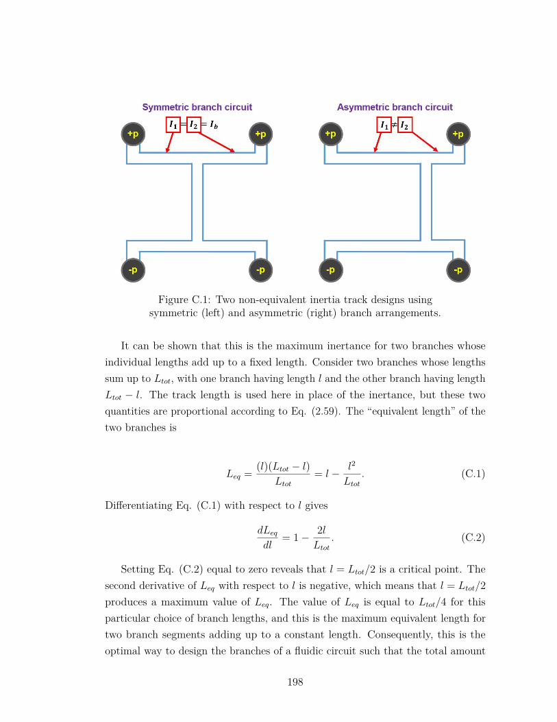
Figure C.1: Two non-equivalent inertia track designs usingsymmetric (left) and asymmetric (right) branch arrangements.
It can be shown that this is the maximum inertance for two branches whoseindividual lengths add up to a fixed length. Consider two branches whose lengthssum up to Ltot, with one branch having length l and the other branch having lengthLtot − l. The track length is used here in place of the inertance, but these twoquantities are proportional according to Eq. (2.59). The “equivalent length” of thetwo branches is
Leq = (l)(Ltot − l)Ltot
= l − l2
Ltot. (C.1)
Differentiating Eq. (C.1) with respect to l gives
dLeqdl
= 1− 2lLtot
. (C.2)
Setting Eq. (C.2) equal to zero reveals that l = Ltot/2 is a critical point. Thesecond derivative of Leq with respect to l is negative, which means that l = Ltot/2produces a maximum value of Leq. The value of Leq is equal to Ltot/4 for thisparticular choice of branch lengths, and this is the maximum equivalent length fortwo branch segments adding up to a constant length. Consequently, this is theoptimal way to design the branches of a fluidic circuit such that the total amount
198

of tubing in the fluidic circuit is minimized. Any other placement of the T-junctionwould result in the two branch segments having a lower inertance contributionand therefore requiring a longer main segment to achieve the desired inertance fortuning.
199
Appendix D|Mechanical Analogy for RotorBlade with F2MC Damper
The dynamics of a rotor blade integrated with an F2MC treatment can be physicallyunderstood by considering an analogous mechanical system consisting of masses,springs, and dampers. The following section explains how to derive the equationsof motion for this equivalent mechanical system. If a modal reduction is usedto reduce the hingeless blade dynamics to one mode, then the same mechanicalanalogy applies to both the hingeless or articulated rotor cases.
Consider a system with the single degree of freedom q governing blade dynamicsand the properties mb, cb, and kb defining the blade modal mass, damping, andstiffness:
mbq + cbq + kbq = BFext + σFt. (D.1)
B and σ are scalars which convert the applied external forcing and F2MC tubeforce into the appropriate loading for the chosen modal coordinates. As describedin Chapter 5, the transfer function from F2MC tube extension xt to F2MC tubeforce Ft for a circuit with an F2MC tube, inertia track, and accumulator is given by
Ft(s)xt(s)
= b2s2 + b1s+ b0
a2s2 + a1s+ a0, (D.2)
where the coefficients are as follows:
200
b2 = (c1c4 − c2c3)Icca
b1 = (c1c4 − c2c3)Rcca
b0 = c1c4 − c2c3 + c1ca
a2 = c4caIc
a1 = c4caRc
a0 = c4 + ca
Alternatively, Eq. (D.2) can be written in the time domain as two equations:
Ft = b2ξ + b1ξ + b0ξ (D.3)
xt = a2ξ + a1ξ + a0ξ (D.4)
Substituting the kinematic relation xt = Ψq into Eq. (D.4), the second equationbecomes
Ψq = a2ξ + a1ξ + a0ξ. (D.5)
Eq. (D.5) can be solved for ξ and substituted back into Eq. (D.3) to yield a newexpression for the dynamics of the F2MC tube force Ft in terms of the degree offreedom q and the state variable ξ,
Ft =(b1 −
b2a1
a2
)ξ +
(b0 −
b2a0
a2
)ξ + b2
a2Ψq. (D.6)
This expression can be substituted into Eq. (D.1) to produce the full systemequation of motion,
mbq + cbq + kbq − σ((
b1 −b2a1
a2
)ξ +
(b0 −
b2a0
a2
)ξ + b2
a2Ψq)
= BFext. (D.7)
Note that the coefficient of the ξ term in the above equation reduces to 0. Eqs.(D.5) and (D.7) can be written in matrix form as
201
mb 00 a2
qξ+
cb 00 a1
qξ+
kb − b2a2σΨ −σ
(b0 − b2a0
a2
)−Ψ a0
qξ =
B0Fext (D.8)
Next, perform a change of variables so that the units of the new state variableλ have the same units as q,
ξ = Ψa0λ. (D.9)
Eq. (D.8) now becomes
mb 00 Ψa2
a0
qλ+
cb 00 Ψa1
a0
qλ+
kb − σΨ b2a2−σΨ
a0
(b0 − b2a0
a2
)−Ψ Ψ
qλ =
B0Fext. (D.10)
From here, multiply the bottom equation by σa0
(b0 − b2a0
a2
)so that the new matrix
system of equations is
mb 00 σΨa2
a02
(b0 − b2a0
a2
)qλ+
cb 00 σΨa1
a02
(b0 − b2a0
a2
)qλ+
kb − σΨ b2a2
−σΨa0
(b0 − b2a0
a2
)−σΨ
a0
(b0 − b2a0
a2
)σΨa0
(b0 − b2a0
a2
) qλ =
B0Fext. (D.11)
Now, consider the two-degree-of-freedom mechanical system depicted in FigureD.1. The matrix equation for this mechanical system ismm 0
0 mf
z1
z2
+cm 0
0 cf
z1
z2
+km + kf −kf−kf kf
z1
z2
=
F0 . (D.12)
The system defined by only mm, cm, and km is analogous to the baseline bladesystem, and the addition of coupling spring kf , absorber mass mf , and dampercf is analogous to the integration of an F2MC damper or damped absorber. Byequating terms in the mass, damping, and stiffness matrices of Eqs. (D.11) and
202
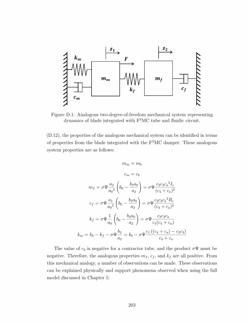
Figure D.1: Analogous two-degree-of-freedom mechanical system representingdynamics of blade integrated with F2MC tube and fluidic circuit.
(D.12), the properties of the analogous mechanical system can be identified in termsof properties from the blade integrated with the F2MC damper. These analogoussystem properties are as follows:
mm = mb
cm = cb
mf = σΨ a2
a02
(b0 −
b2a0
a2
)= σΨ c2c3ca
2Ic(c4 + ca)2
cf = σΨ a1
a02
(b0 −
b2a0
a2
)= σΨ c2c3ca
2Rc
(c4 + ca)2
kf = σΨ 1a0
(b0 −
b2a0
a2
)= σΨ c2c3ca
c4(c4 + ca)
km = kb − kf − σΨ b2
a2= kb − σΨc1 ((c4 + ca)− c2c3)
c4 + ca
The value of c3 is negative for a contractor tube, and the product σΨ must benegative. Therefore, the analogous properties mf , cf , and kf are all positive. Fromthis mechanical analogy, a number of observations can be made. These observationscan be explained physically and support phenomena observed when using the fullmodel discussed in Chapter 5:
203
1. The analogous mass and damping terms mf and cf are directly proportionalto fluid inertance and resistance.
2. The stiffness of the F2MC-integrated blade is higher than the baseline bladestiffness, because km > kb. c1((c4+ca)−c2c3)
c4+ca is a positive quantity and theproduct σΨ is a negative quantity. Physically, the F2MC tube has axialstiffness defined by the parameter c1, and additional stiffness comes from theF2MC tube pumping incompressible fluid into an accumulator with somestiffness.
3. The coupling spring stiffness kf increases with decreasing accumulator capac-itance ca. The coupling spring in the analogy transfers energy from the massmm into the absorber mass mf . In the F2MC system, a stiff accumulatorresists the F2MC tube fluid pumping and allows less fluid mass to oscillatewithin the circuit, reducing the F2MC damper effectiveness. As the absorbermass mf decreases to zero, the analogous mechanical system becomes aspring-mass-damper connected to a “pure damper” governed by a spring anddamper in series.
4. The undamped natural frequency of the spring-mass absorber system is√√√√ kfmf
=√c4 + cac4caIc
. (D.13)
This equation can be useful to estimate the inertance that will tune the circuitfor a given absorber frequency based on a given F2MC tube capacitancec4 and accumulator capacitance ca. For very large values of accumulatorcapacitance ca, the absorber frequency asymptotically approaches
√1
c4Ic.
5. The magnitude of the terms kf , mf , and cf are all proportional to σ andΨ. Increasing all of these terms while holding the properties mm, cm, andkm constant increases the authority of the damper or damped absorber. Forthe hingeless blade model, the magnitudes of both σ and Ψ increase as theF2MC tube distance from the neutral axis increases. Physically, the increasedseparation means that the F2MC tube exerts a larger moment and strainsmore for the same blade deformation. For the articulated blade model, the
204
magnitudes of both σ and Ψ increase as the distance between the lag hingeand the F2MC tube increases.
6. The F2MC tube properties c2 and c3 define how much force the F2MC tubeexerts for a given unit pressure and how much fluid is pumped for a given unitdisplacement. Physically, increasing both of these properties also increasesthe magnitude of kf , mf , and cf .
205
Appendix E|Specifications for ArticulatedRotor Hub
-
206
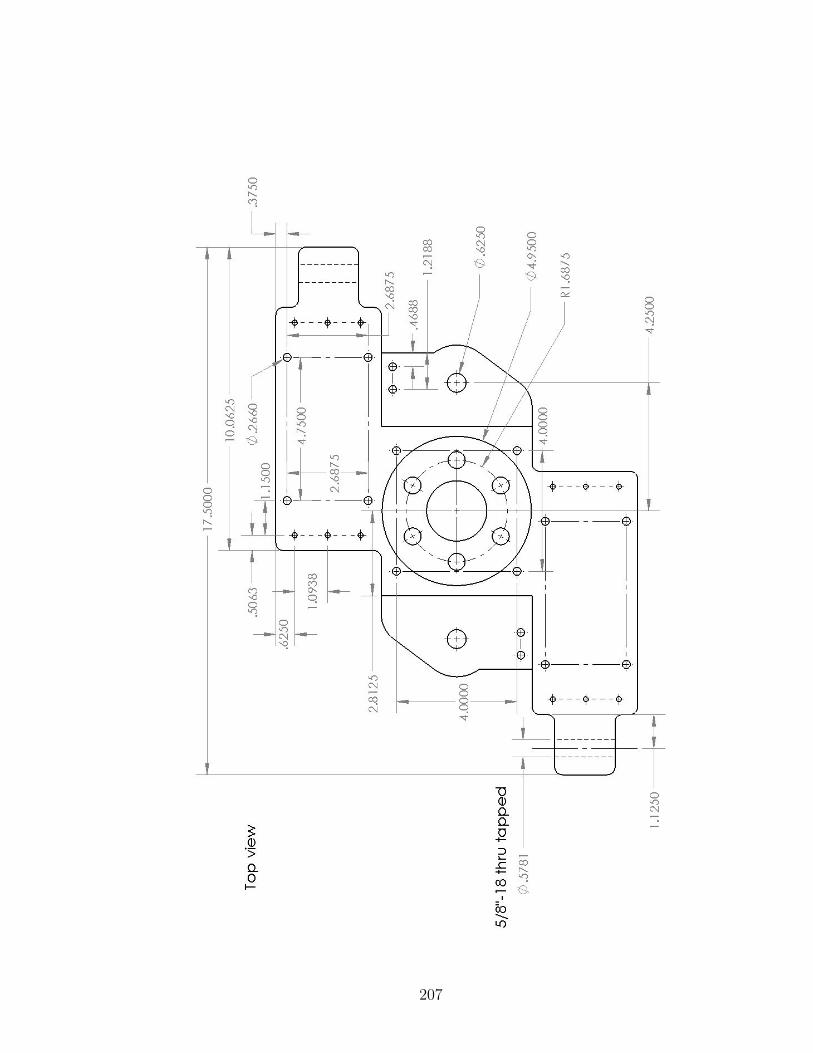
207
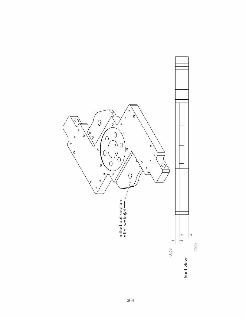
208

Appendix F|Additional Benchtop DamperTest Results
This section contains additional frequency-domain and time-domain results fromthe F2MC damper testing in Chapter 6. Results from both the plastic mesh andstainless steel mesh F2MC tubes are included.
209
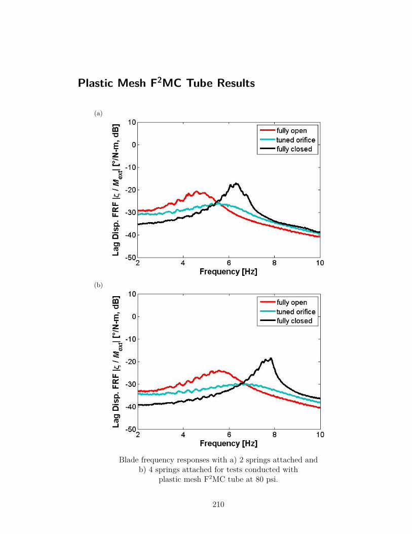
Plastic Mesh F2MC Tube Results
(a)
(b)
Blade frequency responses with a) 2 springs attached andb) 4 springs attached for tests conducted with
plastic mesh F2MC tube at 80 psi.
210
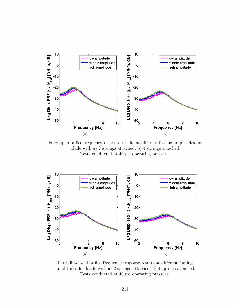
(a) (b)
Fully-open orifice frequency response results at different forcing amplitudes forblade with a) 2 springs attached, b) 4 springs attached.
Tests conducted at 40 psi operating pressure.
(a) (b)
Partially-closed orifice frequency response results at different forcingamplitudes for blade with a) 2 springs attached, b) 4 springs attached.
Tests conducted at 40 psi operating pressure.
211
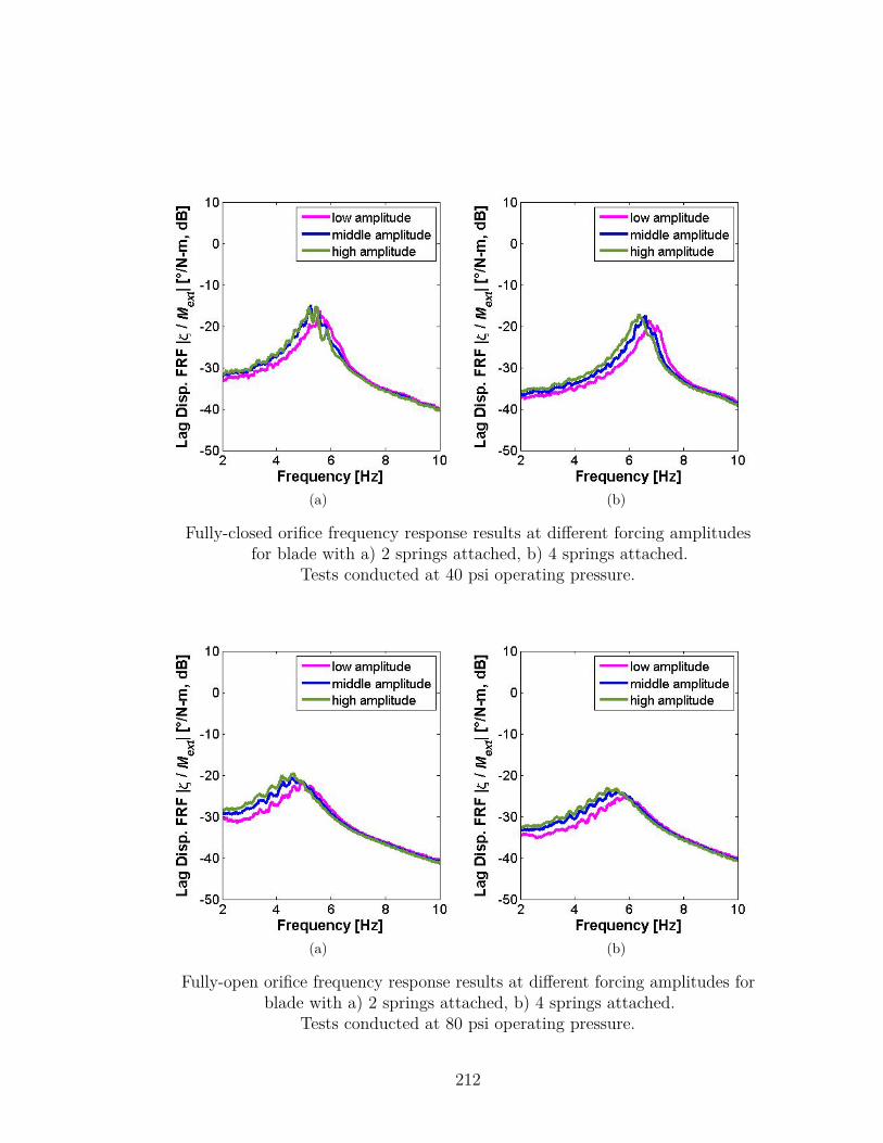
(a) (b)
Fully-closed orifice frequency response results at different forcing amplitudesfor blade with a) 2 springs attached, b) 4 springs attached.
Tests conducted at 40 psi operating pressure.
(a) (b)
Fully-open orifice frequency response results at different forcing amplitudes forblade with a) 2 springs attached, b) 4 springs attached.
Tests conducted at 80 psi operating pressure.
212
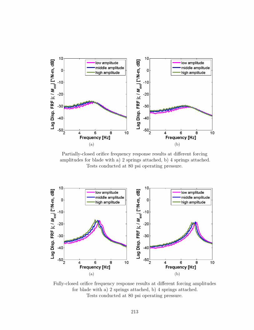
(a) (b)
Partially-closed orifice frequency response results at different forcingamplitudes for blade with a) 2 springs attached, b) 4 springs attached.
Tests conducted at 80 psi operating pressure.
(a) (b)
Fully-closed orifice frequency response results at different forcing amplitudesfor blade with a) 2 springs attached, b) 4 springs attached.
Tests conducted at 80 psi operating pressure.
213
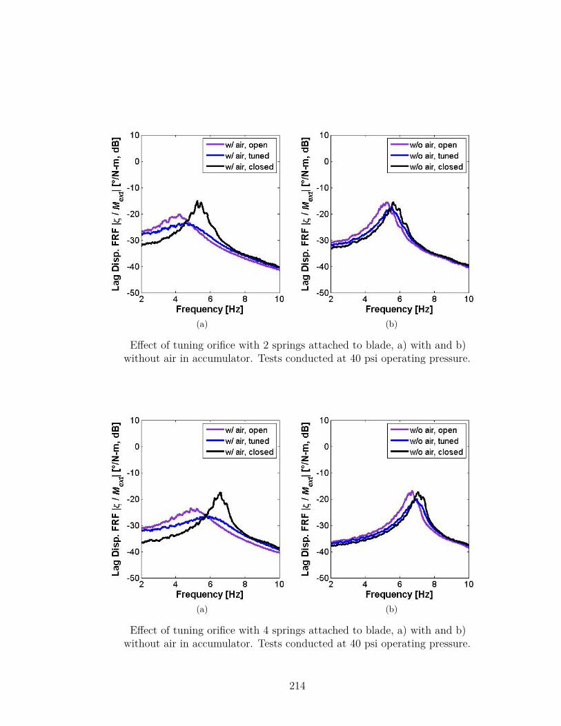
(a) (b)
Effect of tuning orifice with 2 springs attached to blade, a) with and b)without air in accumulator. Tests conducted at 40 psi operating pressure.
(a) (b)
Effect of tuning orifice with 4 springs attached to blade, a) with and b)without air in accumulator. Tests conducted at 40 psi operating pressure.
214
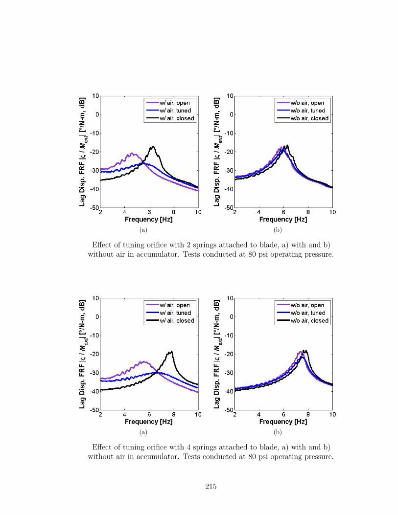
(a) (b)
Effect of tuning orifice with 2 springs attached to blade, a) with and b)without air in accumulator. Tests conducted at 80 psi operating pressure.
(a) (b)
Effect of tuning orifice with 4 springs attached to blade, a) with and b)without air in accumulator. Tests conducted at 80 psi operating pressure.
215
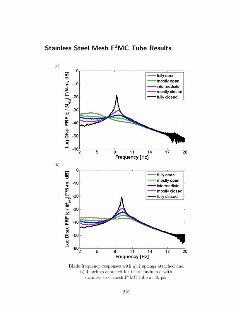
Stainless Steel Mesh F2MC Tube Results
(a)
(b)
Blade frequency responses with a) 2 springs attached andb) 4 springs attached for tests conducted withstainless steel mesh F2MC tube at 40 psi.
216
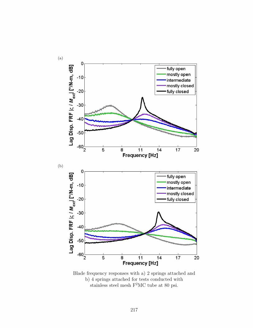
(a)
(b)
Blade frequency responses with a) 2 springs attached andb) 4 springs attached for tests conducted withstainless steel mesh F2MC tube at 80 psi.
217
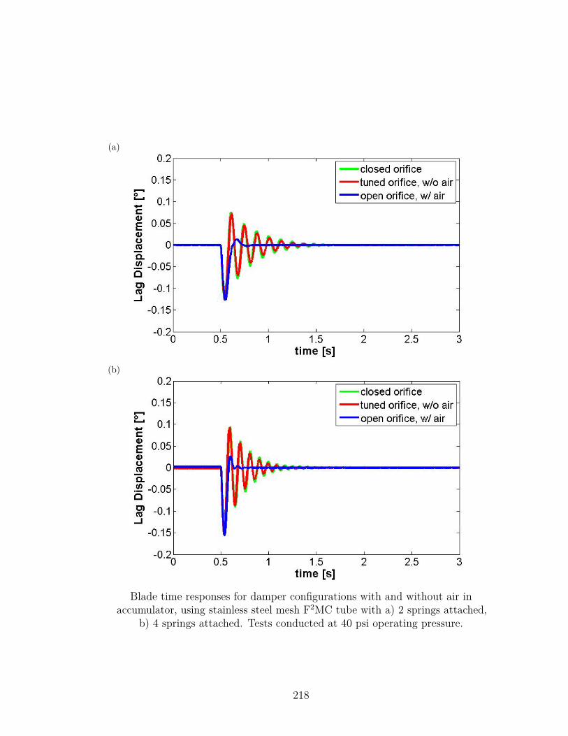
(a)
(b)
Blade time responses for damper configurations with and without air inaccumulator, using stainless steel mesh F2MC tube with a) 2 springs attached,
b) 4 springs attached. Tests conducted at 40 psi operating pressure.
218
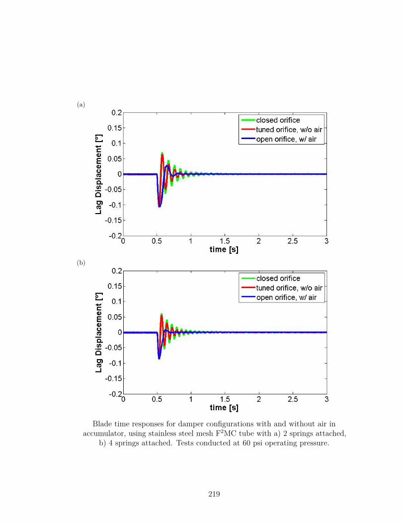
(a)
(b)
Blade time responses for damper configurations with and without air inaccumulator, using stainless steel mesh F2MC tube with a) 2 springs attached,
b) 4 springs attached. Tests conducted at 60 psi operating pressure.
219
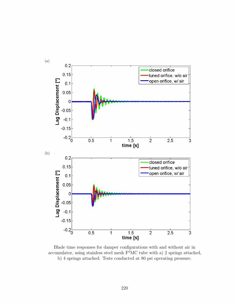
(a)
(b)
Blade time responses for damper configurations with and without air inaccumulator, using stainless steel mesh F2MC tube with a) 2 springs attached,
b) 4 springs attached. Tests conducted at 80 psi operating pressure.
220
Bibliography
[1] Loewy, R., “Helicopter Vibrations: A Technological Perspective,” Journal ofthe American Helicopter Society, Vol. 29, No. 4, 1984, pp. 4–30.
[2] Harrer, K., Yniguez, D., Majar, M., Ellenbecker, D., Estrada, N., and Geiger,M., “Whole Body Vibration Exposure for MH-60S Pilots,” Naval MedicalCenter, San Diego, CA, 2005.
[3] Bielawa, R., Rotary Wing Structural Dynamics and Aeroelasticity, AmericanInstitute of Aeronautics and Astronautics, Reston, VA, 2nd ed., 2006.
[4] Johnson, W., Rotorcraft Aeromechanics, Cambridge University Press, NewYork, NY, 2013.
[5] de Waard, P. and Trouvé, M., “Tail Shake Vibration In Flight: Objective Com-parison Of Aerodynamic Configurations In A Subjective Environment,” Amer-ican Helicopter Society 55th Annual Forum Proceedings, Montréal, Canada,1999.
[6] Pope, M., Wilder, D., and Magnusson, M., “A review of studies on seatedwhole body vibration and low back pain,” Journal of Engineering in Medicine,Vol. 213, No. 6, 1999, pp. 435–446.
[7] Hendricks, M., “The Bell 525’s Smooth Ride,” American Helicopter Society72nd Annual Forum Proceedings, West Palm Beach, FL, 2016.
[8] Krysinski, T. and Malburet, F., Mechanical Vibrations: Active and PassiveControl, ISTE, London, UK, 2007.
[9] Flannelly, W., “The Dynamic Antiresonant Vibration Isolator,” AmericanHelicopter Society 22nd Annual National Forum Proceedings, Washington,D.C., 1966.
[10] Halwes, D., “LIVE - Liquid Inertia Vibration Eliminator,” American HelicopterSociety 36th Annual Forum Proceedings, Washington, D.C., 1980.
221
[11] McGuire, D., “High Stiffness (“Rigid”) Helicopter Pylon Vibration Isola-tion Systems,” American Helicopter Society 59th Annual Forum Proceedings,Phoenix, AZ, 2003.
[12] Smith, M., Lee, T., and Merkley, D., “Active Vibration Treatment UsingPiezo-LIVE Technology,” 46th AIAA/ASME/ASCE/AHS/ASC Structures,Structural Dynamics & Materials Conference, Austin, TX, 2005.
[13] Smith, M. and Redinger, W., “The Model 427 Pylon Isolation System,” Amer-ican Helicopter Society 55th Annual Forum Proceedings, Montréal, Canada,1999.
[14] Romano, P., Seifert, M., and Smith, M., “The 505 Low Vibration Solution,”American Helicopter Society 73rd Annual Forum Proceedings, Fort Worth, TX,2017.
[15] Frahm, H., “Device for damping vibrations of bodies,” U.S. Patent No. 989,958,1911.
[16] Rao, S., Mechanical Vibrations, Prentice Hall, Upper Saddle River, NJ, 5thed., 2011.
[17] Snowdon, J., Vibration and Shock in Damped Mechanical Systems, John Wiley& Sons, New York, NY, 1968.
[18] Sun, J., Jolly, M., and Norris, M., “Passive, Adaptive, and Active TunedVibration Absorbers—A Survey,” Journal of Mechanical Design, Vol. 117,No. B, 1995, pp. 234–242.
[19] Kela, L. and Vähäoja, P., “Recent Studies of Adaptive Tuned VibrationAbsorbers/Neutralizers,” Applied Mechanics Reviews, Vol. 62, No. 6, 2009.
[20] Gaffey, T., Kidd, D., and Grimes, M., “Nonlinear vibration absorber,” U.S.Patent No. 4,766,984, 1988.
[21] Bansemir, H. and Bongers, B., “Apparatus and method for reducing vibrationsof a structure particularly a helicopter,” U.S. Patent No. 6,286,782, 2001.
[22] Duling, C. and Lindner, J., “Evaluating Disruptive Tuned Mass VibrationAttenuators in Rotary Wing Applications,” American Helicopter Society 74thAnnual Forum Proceedings, Phoenix, AZ, 2018.
[23] Vuillet, A. and Zoppitelli, E., “Device for reducing the vibrations on thestructure of a helicopter,” U.S. Patent No. 5,775,637, 1998.
222
[24] Amer, K. and Neff, J., “Vertical-Plane Pendulum Absorbers for MinimizingHelicopter Vibratory Loads,” Journal of the American Helicopter Society,Vol. 19, No. 4, 1974, pp. 44–48.
[25] Paul, W., “Development and Evaluation of the Main Rotor Bifilar Absorber,”American Helicopter Society 25th Annual National Forum Proceedings, Wash-ington, D.C., 1969.
[26] Ganguli, R., Thakkar, D., and Viswamurthy, S., Smart Helicopter Rotors:Optimization and Piezoelectric Vibration Control, Springer, 2016.
[27] Staple, A., “An Evaluation of Active Structural Response as a Means ofReducing Helicopter Vibration,” 15th European Rotorcraft Forum, Amsterdam,Netherlands, 1991.
[28] Pearson, J. and Goodall, R., “Frequency versus time domain adaptive controlalgorithms for the active control of helicopter structural response,” Interna-tional Conference on Control, Edinburgh, Scotland, 1991.
[29] Pearson, J. and Goodall, R., “Adaptive Schemes for the Active Control ofHelicopter Structural Response,” IEEE Transactions on Control SystemsTechnology, Vol. 2, No. 2, 1994, pp. 61–72.
[30] Heverly, D., Smith, E., and Wang, K., “A distributed actuator approach foractive control of helicopter airframe vibration,” 40th Structures, StructuralDynamics, and Materials Conference and Exhibit, St. Louis, MO, 1999.
[31] Heverly, D., Wang, K., and Smith, E., “An Optimal Actuator PlacementMethodology for Active Control of Helicopter Vibrations,” Journal of theAmerican Helicopter Society, Vol. 46, No. 4, 2001, pp. 251–261.
[32] Heverly, D., Singh, R., and Pappas, J., “Adaptive Algorithms for RotorcraftActive Vibration Control,” American Helicopter Society 65th Annual ForumProceedings, Grapevine, TX, 2009.
[33] Mahmood, R. and Heverly, D., “In-Flight Demonstration of Active VibrationControl Technologies on the Bell 429 Helicopter,” American Helicopter Society68th Annual Forum Proceedings, Fort Worth, TX, 2012.
[34] Priems, M., Dreher, S., Konstanzer, P., Hoffmann, F., Kerdreux, B., andJouve, J., “Active Cabin Vibration Control for Light Single and Twin EngineHelicopters,” American Helicopter Society 68th Annual Forum Proceedings,Fort Worth, TX, 2012.
[35] Panza, M., McGuire, D., and Jones, P., “Modeling, Actuation and Controlof an Active Fluid Vibration Isolator,” Journal of Vibration and Acoustics,Vol. 119, No. 1, 1997, pp. 52–59.
223
[36] Cranga, P., Jouve, J., and Skladanek, Y., “Active SARIB®: a New Generationof Suspension for Helicopters,” American Helicopter Society 74th Annual ForumProceedings, Phoenix, AZ, 2018.
[37] Smith, M., Stamps, F., and Pascal, R., “Method and apparatus for improvedvibration isolation,” U.S. Patent 6,695,106, 2004.
[38] Brigley, M., Welsh, W., Altieri, R., and Rich, A., “Design and Testing of aNew Vibration Suppression System,” American Helicopter Society 67th AnnualForum Proceedings, Virginia Beach, VA, 2011.
[39] Andrews, J., Welsh, W., Altieri, R., and DiOttavio, J., “Ground and FlightTesting of a Hub Mounted Vibration Suppression System,” American HelicopterSociety 70th Annual Forum Proceedings, Montréal, Canada, 2014.
[40] Krysinsky, T., “Method and device for reducing the vibration generated onthe structure of a helicopter,” U.S. Patent No. 5,816,533, 1998.
[41] Eglin, P., “Method for using a steerable tail fin to reduce the vibration generatedon the fuselage of a helicopter,” U.S. Patent 7,461,819, 2008.
[42] Manfredotti, T., “Device for reducing the vibration generated on the structureof a rotary-wing aircraft,” U.S. Patent 6,279,704, 2001.
[43] Strehlow, H., Rottmayr, H., Duerr, J., and Zaglauer, H., “Method for dampingrear extension arm vibrations of rotorcraft and rotorcraft with a rear extensionarm vibration damping device,” U.S. Patent Application 20080173754, 2008.
[44] Klöppel, V., Jänker, P., Konstanzer, P., and Dieterich, O., “Apparatus andmethod for reducing, avoiding or eliminating lateral vibrations of a helicopter,”EU Patent 2,687,440, 2014.
[45] Monico, M., DiOttavio, J., and Kakaley, D., “Achieving Near Zero N/RevVibration with Zero-VibeTM Technology,” American Helicopter Society 74thAnnual Forum Proceedings, Phoenix, AZ, 2018.
[46] Kessler, C., “Active rotor control for helicopters: motivation and survey onhigher harmonic control,” 36th European Rotorcraft Forum, Paris, France,2010.
[47] Cronjé, J., Heyns, P., Theron, N., and Loveday, P., “Development of a VariableStiffness and Damping Tunable Vibration Isolator,” Journal of Vibration andControl, Vol. 11, No. 3, 2005, pp. 381–396.
[48] du Plooy, N., Heyns, P., and Brennan, M., “The development of a tunablevibration absorbing isolator,” International Journal of Mechanical Sciences,Vol. 47, No. 7, 2005, pp. 983–997.
224
[49] Smith, M. and Stamps, F., “Vibration isolation system,” U.S. Patent 5,435,531,1995.
[50] Hiemenz, G., Hu, W., and Wereley, N., “Semi-Active MagnetorheologicalHelicopter Crew Seat Suspension for Vibration Isolation,” Journal of Aircraft,Vol. 45, No. 3, 2008, pp. 945–953.
[51] Bansemir, H. and Bongers, B., “Mass damper,” U.S. Patent 6,009,986, 2000.
[52] du Bois, J., Lieven, N., and Adhikari, S., “Adaptive Passive Control of DynamicResponse Through Structural Loading,” 48th AIAA/ASME/ASCE/AHS/ASCStructures, Structural Dynamics, and Materials Conference, Honolulu, HI,2007.
[53] du Bois, J., Lieven, N., and Adhikari, S., “A tensioned cable as an adaptivetuned vibration absorber for response suppression in rotorcraft,” ISMA 2012International Conference on Noise and Vibration Engineering, Leuven, 2012.
[54] Almeras, P., “Active control of aeromechanical stability applied by Eurocopter,”23rd European Rotorcraft Forum, Dresden, Germany, 1997.
[55] McGuire, D., “Fluidlastic® Dampers and Isolators for Vibration Control inHelicopters,” American Helicopter Society 50th Annual Forum Proceedings,Washington, D.C., 1994.
[56] Jones, P., Russell, D., and McGuire, D., “Latest Developments in Fluidlastic®Lead-Lag Dampers for Vibration Control in Helicopters,” American HelicopterSociety 59th Annual Forum Proceedings, Phoenix, AZ, 2003.
[57] Panda, B., Mychalowycz, E., and Tarzanin, F., “Application of passive dampersto modern helicopters,” Smart Materials and Structures, Vol. 5, No. 5, 1996,pp. 509–516.
[58] Domke, B., “Aviation Images,” http://www.b-domke.de/AviationImages.html,2018.
[59] Ruddell, A. and Macrino, J., “Advancing Blade Concept (ABC)TM High SpeedDevelopment,” American Helicopter Society 36th Annual Forum Proceedings,Washington, D.C., 1980.
[60] Abbe, J., Blackwell, R., and Jenney, D., “Advanced Blade Concept (ABC)TM
Dynamics,” 33rd Annual National Forum of the American Helicopter SocietyProceedings, Washington, D.C., 1977.
[61] Blackwell, R. and Millott, T., “Dynamics Design Characteristics of the SikorskyX2 TechnologyTM Demonstrator Aircraft,” American Helicopter Society 64thAnnual Forum Proceedings, Montréal, Canada, 2008.
225
[62] Walsh, D., Weiner, S., Arifian, K., Bagai, A., Lawrence, T., and Blackwell,R., “Development Testing of the Sikorsky X2 TechnologyTM Demonstrator,”American Helicopter Society 65th Annual Forum Proceedings, Grapevine, TX,2009.
[63] Walsh, D., Weiner, S., Arifian, K., Lawrence, T., Wilson, M., Millott, T.,and Blackwell, R., “High Airspeed Testing of the Sikorsky X2 TechnologyTM
Demonstrator,” American Helicopter Society 67th Annual Forum Proceedings,Virginia Beach, VA, 2011.
[64] Liu, W. and Rahn, C., “Fiber-Reinforced Membrane Models of McKibbenActuators,” Journal of Applied Mechanics, Vol. 70, No. 6, 2003, pp. 853–859.
[65] Lekhnitskii, S., Theory of Elasticity of an Anisotropic Body, Mir Publishers,Moscow, Russia, 1981.
[66] Shan, Y., Lotfi, A., Philen, M., Li, S., Bakis, C., Rahn, C., and Wang, K.,“Fluidic flexible matrix composites for autonomous structural tailoring,” SPIE6525, Active and Passive Smart Structures and Integrated Systems 2007 , 2007.
[67] Shan, Y., Philen, M., Lotfi, A., Li, S., Bakis, C., Rahn, C., and Wang, K.,“Variable Stiffness Structures Utilizing Fluidic Flexible Matrix Composites,”Journal of Intelligent Material Systems and Structures, Vol. 20, No. 4, 2009,pp. 443–456.
[68] Scarborough III, L., Rahn, C., and Smith, E., “Fluidic Composite TunableVibration Isolators,” Journal of Vibration and Acoustics, Vol. 134, No. 1, 2012.
[69] Shan, Y., Philen, M., Bakis, C., Wang, K., and Rahn, C., “Nonlinear-elasticfinite axisymmetric deformation of flexible matrix composite membranes underinternal pressure and axial force,” Composites Science and Technology, Vol. 66,No. 15, 2006, pp. 3053–3063.
[70] Zhu, B., Rahn, C., and Bakis, E., “Tailored Fluidic Composites for Stiffnessor Volume Change,” ASME 2011 Conference on Smart Materials, AdaptiveStructures and Intelligent Systems, Scottsdale, AZ, 2011.
[71] Lotfi-Gaskarimahalle, A., Scarborough III, L., Rahn, C., and Smith, E., “Tun-able fluidic composite mounts for vibration absorption,” Journal of Vibrationand Control, Vol. 20, No. 14, 2014, pp. 2137–2145.
[72] Zhu, B., Rahn, C., and Bakis, C., “Fluidic Flexible Matrix Composite DampingTreatment for a Cantilever Beam,” Journal of Sound and Vibration, Vol. 340,2015, pp. 80–94.
226
[73] Zhu, B., Rahn, C., and Bakis, C., “Fluidic Flexible Matrix Composite VibrationAbsorber for a Cantilever Beam,” Journal of Vibration and Acoustics, Vol. 137,No. 2, 2015.
[74] Miura, K., Krott, M., Smith, E., Rahn, C., and Romano, P., “ExperimentalValidation of Tailboom Vibration Control Using Fluidic Flexible Matrix Com-posite Tubes,” American Helicopter Society 71st Annual Forum Proceedings,Virginia Beach, VA, 2015.
[75] Miura, K., Rahn, C., and Smith, E., “Passive Tailboom Vibration Control UsingFluidic Flexible Matrix Composite Tubes,” 55th AIAA/ASME/ASCE/AH-S/ASC Structures, Structural Dynamics, and Materials Conference, NationalHarbor, MD, 2014.
[76] Heverly, D., Optimal Actuator Placement and Active Structure Design forControl of Helicopter Airframe Vibrations, Ph.D. thesis, The PennsylvaniaState University, 2002.
[77] Kattan, P., MATLAB Guide to Finite Elements: An Interactive Approach,Springer, Berlin, Germany, 2007.
[78] Miura, K., Modeling, Design, and Experimental Validation of a TailboomVibration Absorber Using Fluidic Flexible Matrix Composite Tubes, Ph.D.thesis, The Pennsylvania State University, 2016.
[79] Donovan, F., Taylor, B., and Su, M., “One-Dimensional Computer Analysisof Oscillatory Flow in Rigid Tubes,” Journal of Biomechanical Engineering,Vol. 113, No. 4, 1991, pp. 476–484.
[80] Jinghong, Y., Zhaoneng, C., and Yuanzhang, L., “The Variation of Oil EffectiveBulk Modulus With Pressure in Hydraulic Systems,” Journal of DynamicSystems, Measurement, and Control, Vol. 116, No. 1, 1994, pp. 146–150.
[81] Logan, D., A First Course In The Finite Element Method, Thomson, Toronto,Canada, 4th ed., 2007.
[82] Tondu, B., “Modelling of the McKibben artificial muscle: A review,” Journal ofIntelligent Material Systems and Structures, Vol. 23, No. 3, 2012, pp. 225–253.
[83] Potter, J., McGuire, D., and Brubaker, E., “Elastomers + Fluids + Electronics= Improved Comfort and Reliability for Aircraft,” 21st European RotorcraftForum, St. Petersburg, Russia, 1995.
[84] Macia, N. and Thaler, G., Modeling and Control of Dynamic Systems, ThomsonDelmar Learning, Clifton Park, NY, 2007.
227
[85] Kang, H. and Glaz, B., “Aeroelastic Stability Analysis of Stiff-in-plane HingelessRotors,” American Helicopter Society 74th Annual Forum Proceedings, Phoenix,AZ, 2018.
[86] Lesieutre, G., “Frequency-Independent Modal Damping for Flexural Structuresvia a Viscous ‘Geometric’ Damping Model,” Journal of Guidance, Control,and Dynamics, Vol. 33, No. 6, 2010, pp. 1931–1935.
[87] Lesieutre, G. and Kauffman, J., “‘Geometric’ Viscous Damping Model forNearly Constant Beam Modal Damping,” AIAA Journal, Vol. 51, No. 7, 2013,pp. 1688–1694.
[88] Bagai, A., “Aerodynamic Design of the X2 Technology DemonstratorTM MainRotor Blade,” American Helicopter Society 64th Annual Forum Proceedings,Montréal, Canada, 2008.
[89] Peterson, R. and Johnson, W., “Aeroelastic Loads and Stability Investigationof a Full-Scale Hingeless Rotor,” DGLR/AAAF/AIAA/RAeS InternationalForum on Aeroelasticity and Structural Dynamics, Aachen, Germany, 1991.
[90] Woods, B., Gentry, M., Kothera, C., and Wereley, N., “Fatigue life testing ofswaged pneumatic artificial muscles as actuators for aerospace applications,”Journal of Intelligent Material Systems and Structures, Vol. 23, No. 3, 2012,pp. 327–343.
[91] Tsagarakis, N. and Caldwell, D., “Improved Modeling and Assessment ofpneumatic Muscle Actuators,” IEEE International Conference on Roboticsand Automation, San Francisco, CA, 2000.
[92] Bauchau, O. and Liu, H., “On the Modeling of Hydraulic Components in Rotor-craft Systems,” American Helicopter Society 62nd Annual Forum Proceedings,Phoenix, AZ, 2006.
228
VitaMatthew J. Krott
EducationThe Pennsylvania State University
Doctor of Philosophy, Mechanical Engineering, December 2018Master of Science, Mechanical Engineering, May 2017Bachelor of Science with honors, Mechanical Engineering, May 2013
Selected Conference Publications• Krott, M., Smith, E.C., Palacios, J., and Rahn, C.D., “Modeling, Development,
and Testing of Fluidic Flexible Matrix Composite Blade Dampers,” AmericanHelicopter Society 74th Annual Forum Proceedings, Phoenix, AZ, May 2018.
• Krott, M., Smith, E.C., and Rahn, C.D., “Experimental Validation of Multi-ModeTailboom Passive Vibration Control Using Fluidic Flexible Matrix CompositeTubes,” American Helicopter Society 73rd Annual Forum Proceedings, Fort Worth,TX, May 2017.
• Krott, M., Miura, K., Rahn, C.D., and Smith, E.C. “Finite Element Modeling ofFluidic Flexible Matrix Composite (F2MC) Treatments for Bending and TorsionalVibration Control,” 57th AIAA/ASCE/AHS/ASC Structures, Structural Dynamics,and Materials Conference, San Diego, CA, January 2016.
• Miura, K., Krott, M., Smith, E., Rahn, C., and Romano, P., “ExperimentalDemonstration of Tailboom Vibration Reduction Using Fluidic Flexible MatrixComposite Tubes,” American Helicopter Society 71st Annual Forum Proceedings,Virginia Beach, VA, May 2015.
Selected Journal Publications• Krott, M.J., Smith, E.C., and Rahn, C.D., “Modeling and Testing of Fluidic Flexible
Matrix Composite Lead-Lag Dampers,” Journal of the American Helicopter Society(in preparation).
• Krott, M.J., Smith, E.C., and Rahn, C.D., “Coupled and Multi-Mode TailboomVibration Control Using Fluidic Flexible Matrix Composite Tubes,” Journal of theAmerican Helicopter Society (submitted for review).
• Miura, K., Krott, M.J., Smith, E.C., and Rahn, C.D., “Experimental Demonstrationof a Vibration Absorber Using Braid-Sheathed Fluidic Flexible Matrix CompositeTubes,” Journal of the American Helicopter Society (accepted with revision).
Related Documents