1 Inductive sensors The operating principle is based on the following relationship: L=f(x) M=g(x) •High robusteness against influencing quantities (environmental)

Welcome message from author
This document is posted to help you gain knowledge. Please leave a comment to let me know what you think about it! Share it to your friends and learn new things together.
Transcript

1
Inductive sensors
The operating principle is based on the
following relationship:
L=f(x)
M=g(x)
•High robusteness against influencing
quantities (environmental)

2
Basics
N
i
h1
h2
fmm = Ni = magnetic flux x reluctance= F x R [A-spire]
NiF
R[Weber]
The magnetomotive force is:
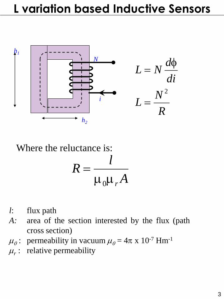
L variation based Inductive Sensors
3
N
i
h1
h2
R
NL
di
dNL
2
Where the reluctance is:
l: flux path
A: area of the section interested by the flux (path
cross section)
m0 : permeability in vacuum m0 = 4p x 10-7 Hm-1
mr : relative permeability
A
lR
rmm
0
L variation based Inductive Sensors
4
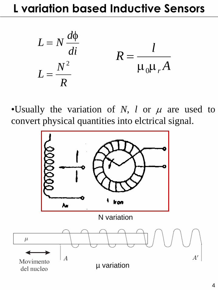
•Usually the variation of N, l or m are used to
convert physical quantities into elctrical signal.
N variation
L variation based Inductive Sensors
R
NL
di
dNL
2
A
lR
rmm
0
µ variation
5
Advantages:
•Robustness against environmental quantities
•Reduced load effects
•High responsivity
Drawbacks:
•Sensitivity to magnetic field: shielding;
•Side effects reduce the operating range.
•Must work below the Curie Temperature.
Materials:
•In Vacuum: low responsivity, high frequency
operation
•Ferromagnetic core: high responsivity, low
frequency operation (<20kHz).
L variation based Inductive Sensors
6
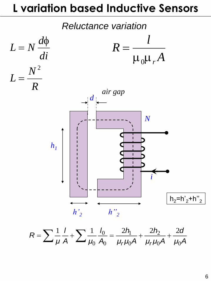
d air gap
N
i
h1
h’’2
Aμ
d
Aμμ
h
Aμμ
h
A
l
μA
l
μR
rr 00
2
0
1
0
0
0
22211
h’2
h2=h’2+h’’2
L variation based Inductive Sensors
Reluctance variation
A
lR
rmm
0
R
NL
di
dNL
2

7 Non linear behaviour with d !!
0
0
00
210
0
con )1(
222
R
kdxxRR
Aμk,
Aμμ
hhR
kdRR
r
0
2
0
0
0
22
eing
1)1(
R
NLb
x
L
xR
N
R
NL
L variation based Inductive Sensors
Reluctance variation
R0 takes into account
flux path through the coil
and not through the air!
Aμ
d
Aμμ
h
Aμμ
h
A
l
μA
l
μR
rr 00
2
0
1
0
0
0
22211
dair gap
N
i
h1
h’’2
8
L variation based Inductive Sensors
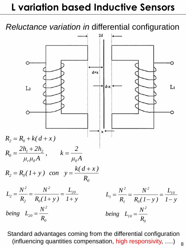
Reluctance variation in differential configuration
0
02
00r
210
02
R
)xd(ky con )y1(RR
Aμ
2k,
Aμμ
h2h2R
)xd(kRR
0
2
20
20
0
2
2
2
2
R
NL eingb
y1
L
)y1(R
N
R
NL
0
2
10
10
0
2
1
2
1
R
NL eingb
y1
L
)y1(R
N
R
NL
Standard advantages coming from the differential configuration
(influencing quantities compensation, high responsivity, ….)
9
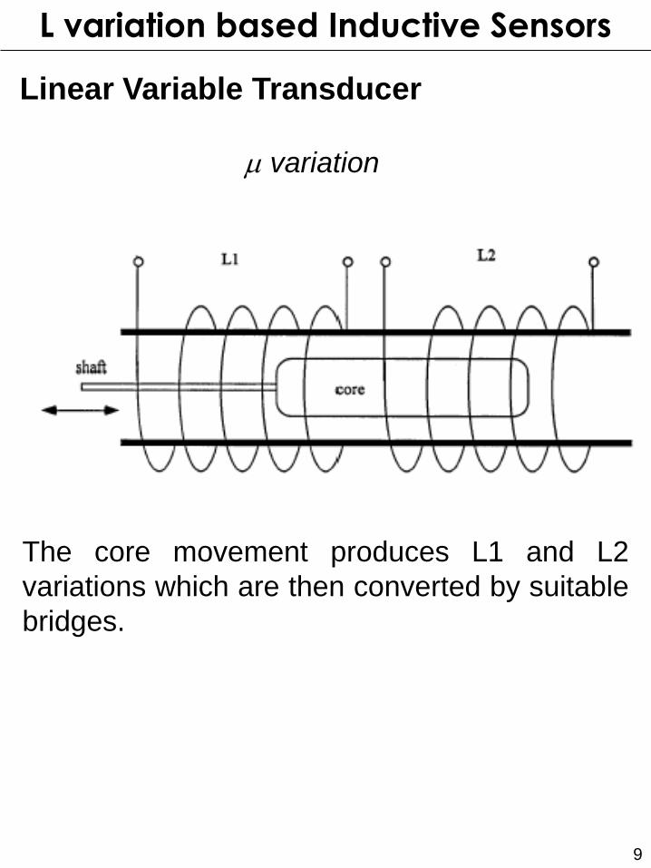
Linear Variable Transducer
The core movement produces L1 and L2
variations which are then converted by suitable
bridges.
L variation based Inductive Sensors
m variation
10
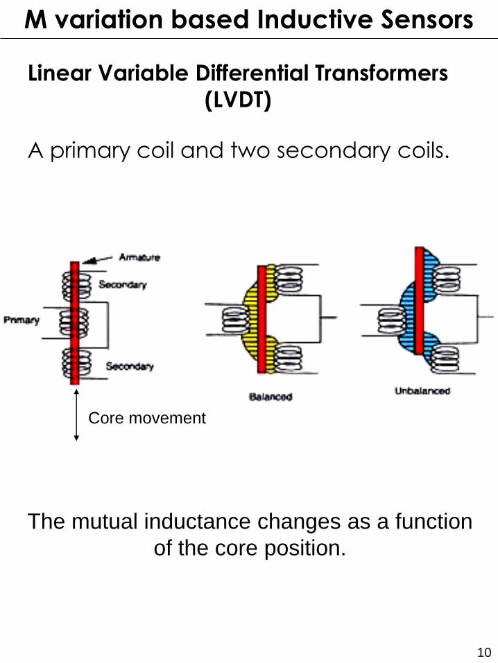
A primary coil and two secondary coils.
Linear Variable Differential Transformers
(LVDT)
The mutual inductance changes as a function
of the core position.
Core movement
M variation based Inductive Sensors
11
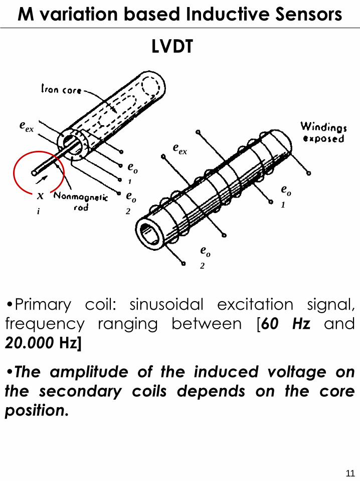
•Primary coil: sinusoidal excitation signal,
frequency ranging between [60 Hz and
20.000 Hz]
•The amplitude of the induced voltage on
the secondary coils depends on the core position.
eo
1
eo
2
eex
x
i
eo
1
eo
2
eex
LVDT
M variation based Inductive Sensors
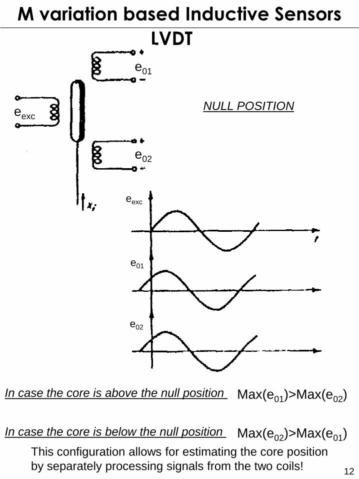
12
LVDT
e01
e02
eexc
M variation based Inductive Sensors
NULL POSITION
e02
e01
eexc
In case the core is above the null position Max(e01)>Max(e02)
In case the core is below the null position Max(e02)>Max(e01)
This configuration allows for estimating the core position
by separately processing signals from the two coils!

13
LVDT
Secondary coils in differential configuration
e0 eexc
M variation based Inductive Sensors
Advantages coming from the
differential configuration:
•influencing quantities compensation;
•high responsivity;
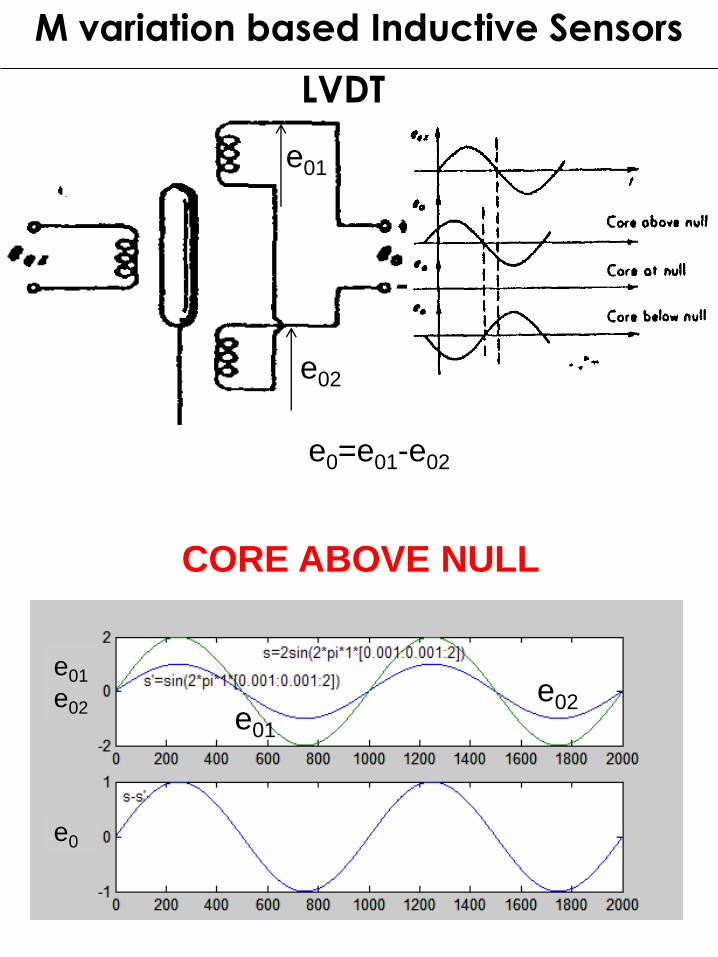
LVDT
e01
e02
e0
M variation based Inductive Sensors
e01
e02
e01
e02
e0=e01-e02
CORE ABOVE NULL
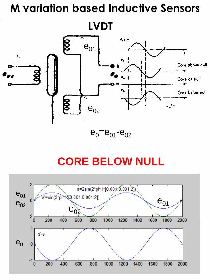
LVDT
e01
e02
e0
M variation based Inductive Sensors
e01
e02
e02
e01
e0=e01-e02
CORE BELOW NULL
17
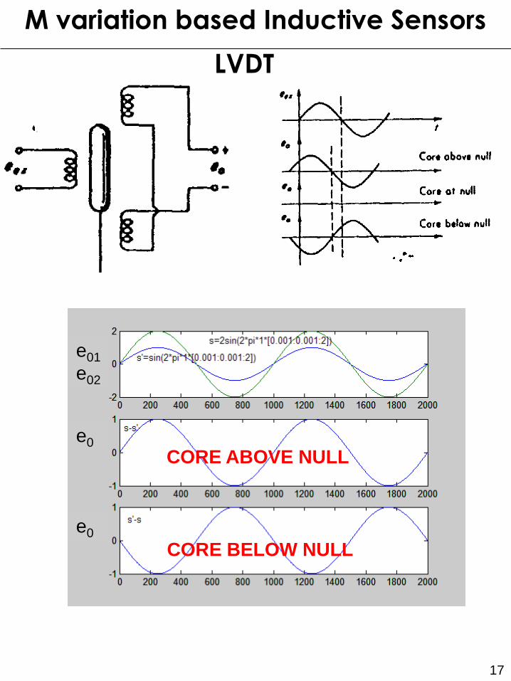
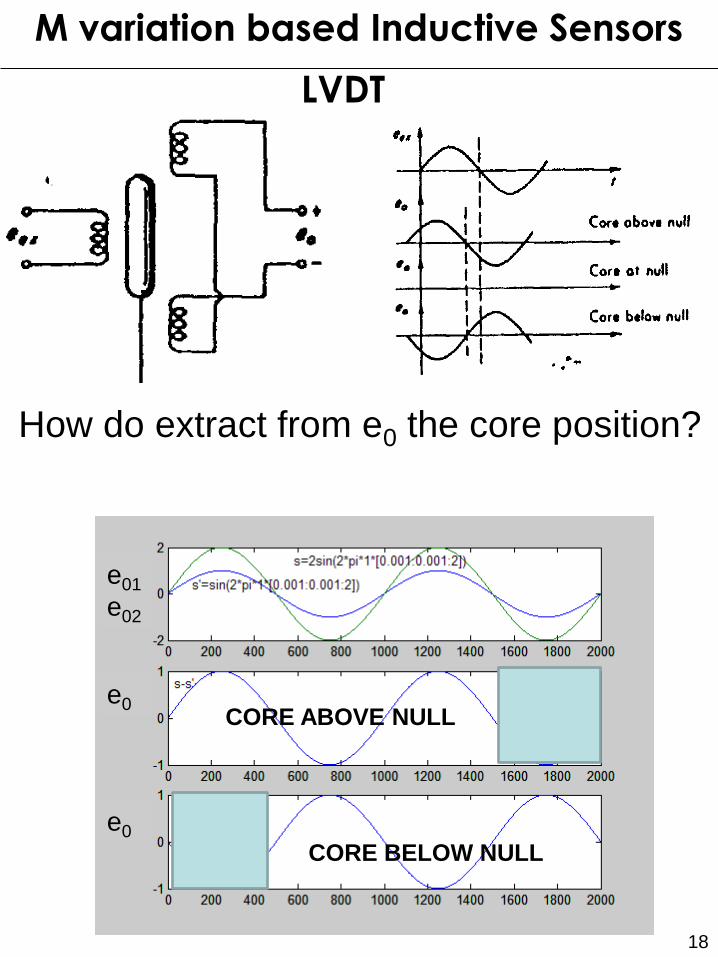
LVDT
e01
e02
e0
e0
M variation based Inductive Sensors
CORE BELOW NULL
CORE ABOVE NULL
18
LVDT
e01
e02
e0
e0
M variation based Inductive Sensors
How do extract from e0 the core position?
CORE ABOVE NULL
CORE BELOW NULL
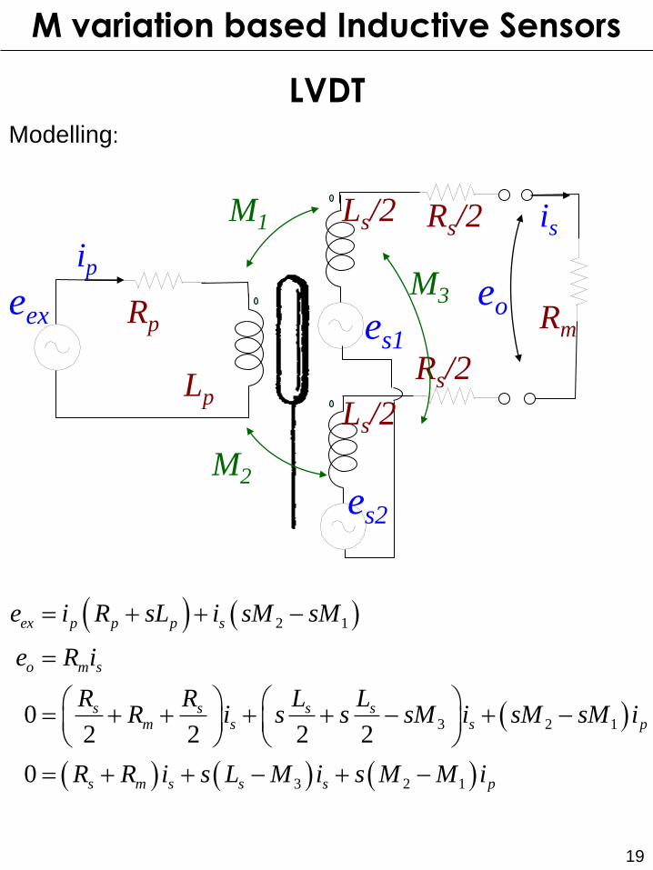
19
LVDT Modelling:
eex es1
es2
Ls/2
Ls/2
Rm
Rs/2
Rs/2
Rp
Lp
M1
M2
ip
is
M3 eo
2 1
3 2 1
3 2 1
02 2 2 2
0
ex p p p s
o m s
s s s sm s s p
s m s s s p
e i R sL i sM sM
e R i
R R L LR i s s sM i sM sM i
R R i s L M i s M M i
M variation based Inductive Sensors
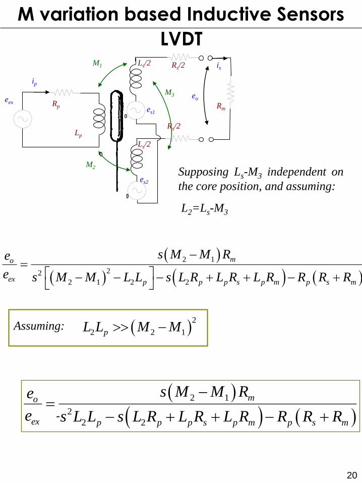
20
LVDT
eex
es1
es2
Ls/2
Ls/2
Rm
Rs/2
Rs/2
Rp
Lp
M1
M2
ip
is
M3 eo
Supposing Ls-M3 independent on
the core position, and assuming:
L2=Ls-M3
2 1
22
2 1 2 2
mo
ex p p p s p m p s m
s M M Re
e s M M L L s L R L R L R R R R
Assuming: 2
2 2 1pL L M M
2 1
2
2 2
mo
ex p p p s p m p s m
s M M Re
e s L L s L R L R L R R R R
-
M variation based Inductive Sensors
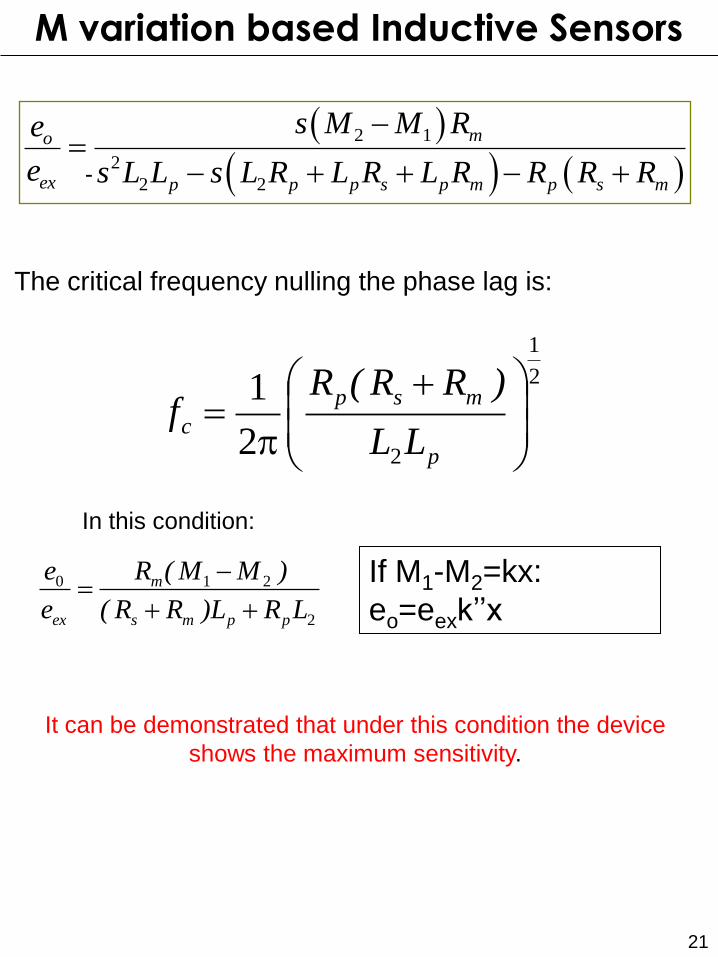
21
The critical frequency nulling the phase lag is:
2
1
22
1
p
p
msp
cLL
)RR(Rf
2
210
LRL)RR(
)MM(R
e
e
ppms
m
ex
In this condition:
It can be demonstrated that under this condition the device
shows the maximum sensitivity.
If M1-M2=kx:
eo=eexk’’x
M variation based Inductive Sensors
2 1
2
2 2
mo
ex p p p s p m p s m
s M M Re
e s L L s L R L R L R R R R
-
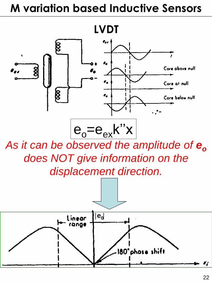
22
LVDT
As it can be observed the amplitude of eo
does NOT give information on the
displacement direction.
e0
eo=eexk’’x
M variation based Inductive Sensors
23
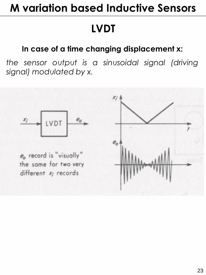
LVDT
In case of a time changing displacement x:
the sensor output is a sinusoidal signal (driving signal) modulated by x.
M variation based Inductive Sensors
24
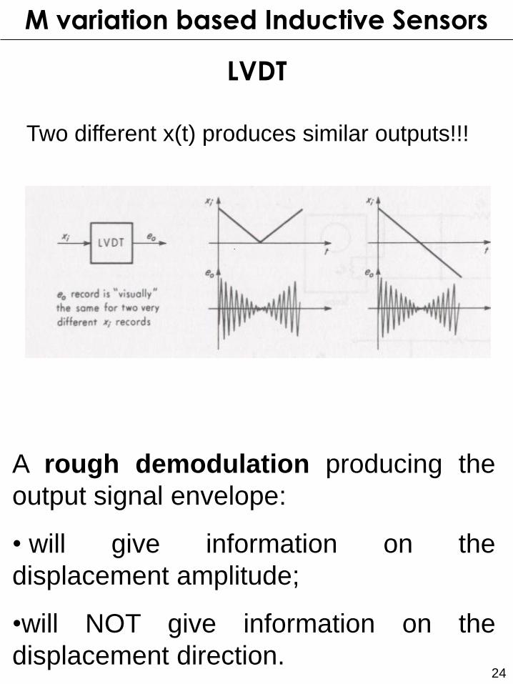
LVDT
A rough demodulation producing the
output signal envelope:
• will give information on the
displacement amplitude;
•will NOT give information on the
displacement direction.
M variation based Inductive Sensors
Two different x(t) produces similar outputs!!!
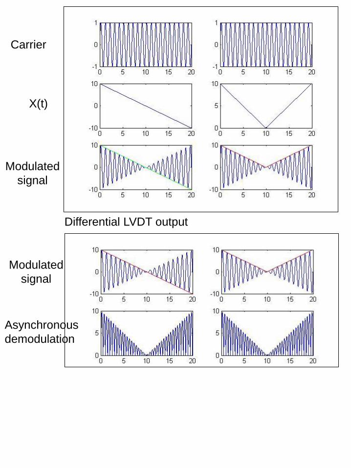
Differential LVDT output
Asynchronous
demodulation
Carrier
X(t)
Modulated
signal
Modulated
signal
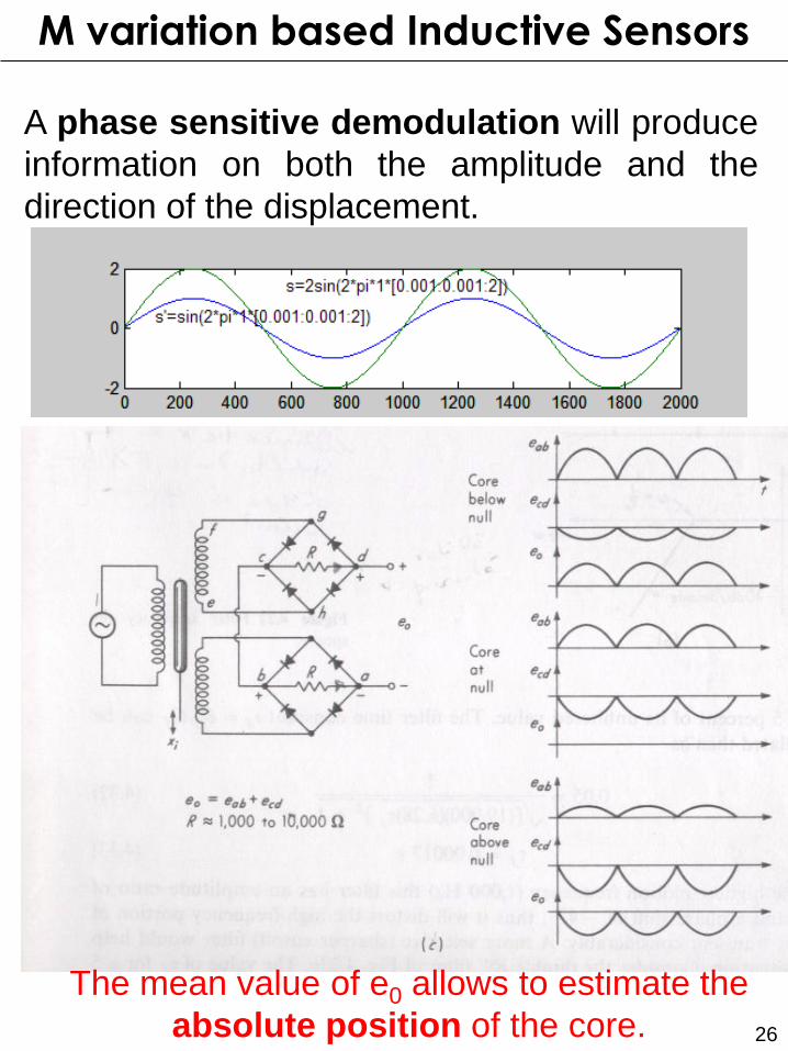
26
The mean value of e0 allows to estimate the
absolute position of the core.
A phase sensitive demodulation will produce
information on both the amplitude and the
direction of the displacement.
M variation based Inductive Sensors

27
LVDT
A phase sensitive demodulation will produce
information on both the amplitude and the
direction of the displacement.
.
M variation based Inductive Sensors
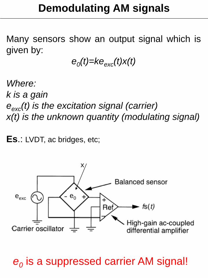
Demodulating AM signals
Many sensors show an output signal which is
given by:
e0(t)=keexc(t)x(t)
Where:
k is a gain
eexc(t) is the excitation signal (carrier)
x(t) is the unknown quantity (modulating signal)
Es.: LVDT, ac bridges, etc;
eexc e0
x
e0 is a suppressed carrier AM signal!
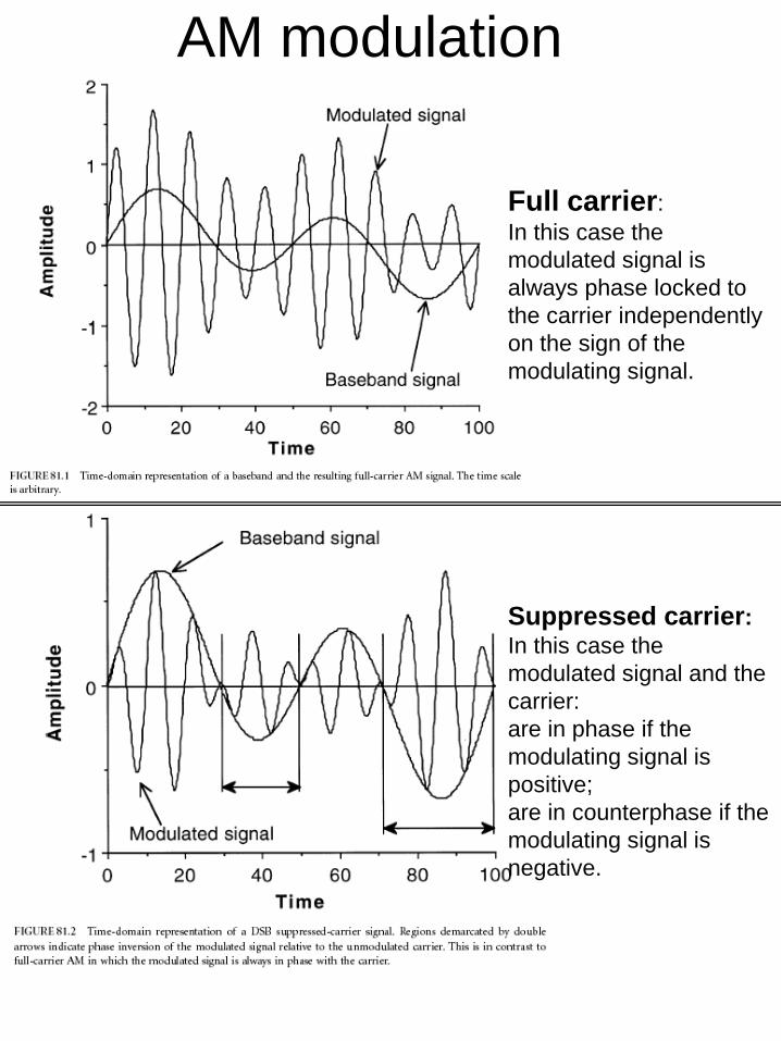
AM modulation
Full carrier:
In this case the
modulated signal is
always phase locked to
the carrier independently
on the sign of the
modulating signal.
Suppressed carrier:
In this case the
modulated signal and the
carrier:
are in phase if the
modulating signal is
positive;
are in counterphase if the
modulating signal is
negative.
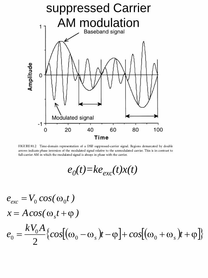
tcostcosAkV
e
)tcos(Ax
)tcos(Ve
ss
s
exc
000
0
00
2
e0(t)=keexc(t)x(t)
suppressed Carrier
AM modulation
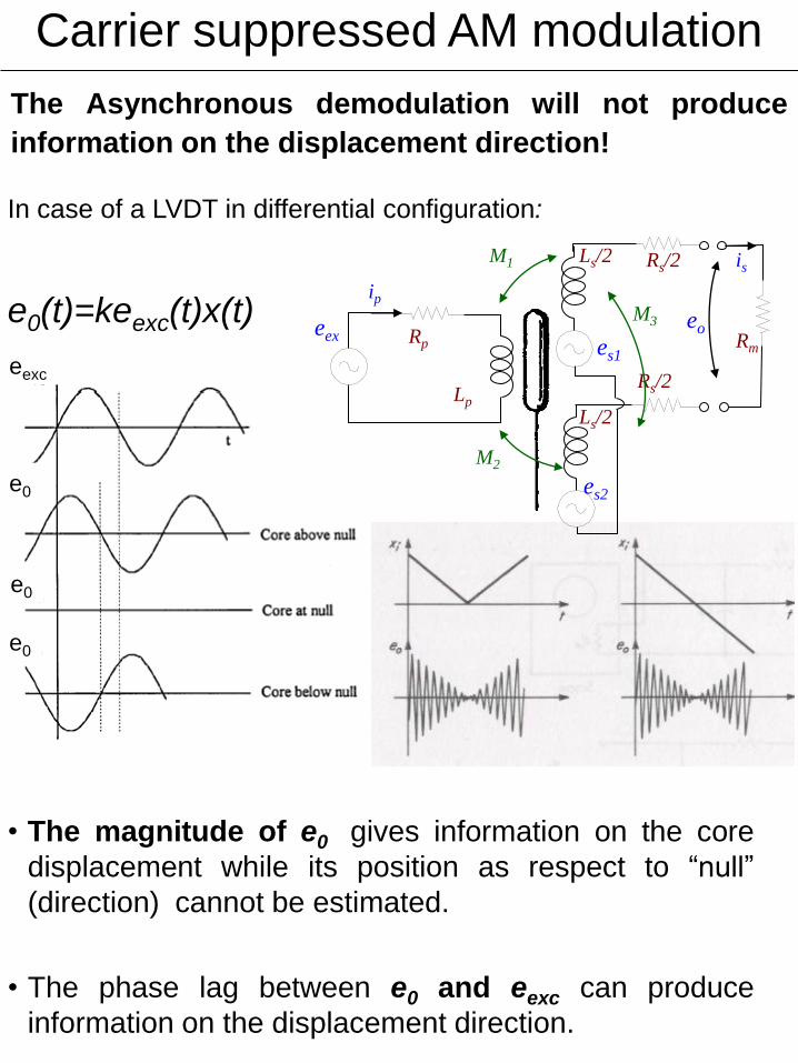
In case of a LVDT in differential configuration:
e0(t)=keexc(t)x(t)
• The magnitude of e0 gives information on the core
displacement while its position as respect to “null”
(direction) cannot be estimated.
• The phase lag between e0 and eexc can produce
information on the displacement direction.
eexc
e0
e0
e0
eex es1
es2
Ls/2
Ls/2
Rm
Rs/2
Rs/2
Rp
Lp
M1
M2
ip
is
M3 eo
The Asynchronous demodulation will not produce
information on the displacement direction!
Carrier suppressed AM modulation
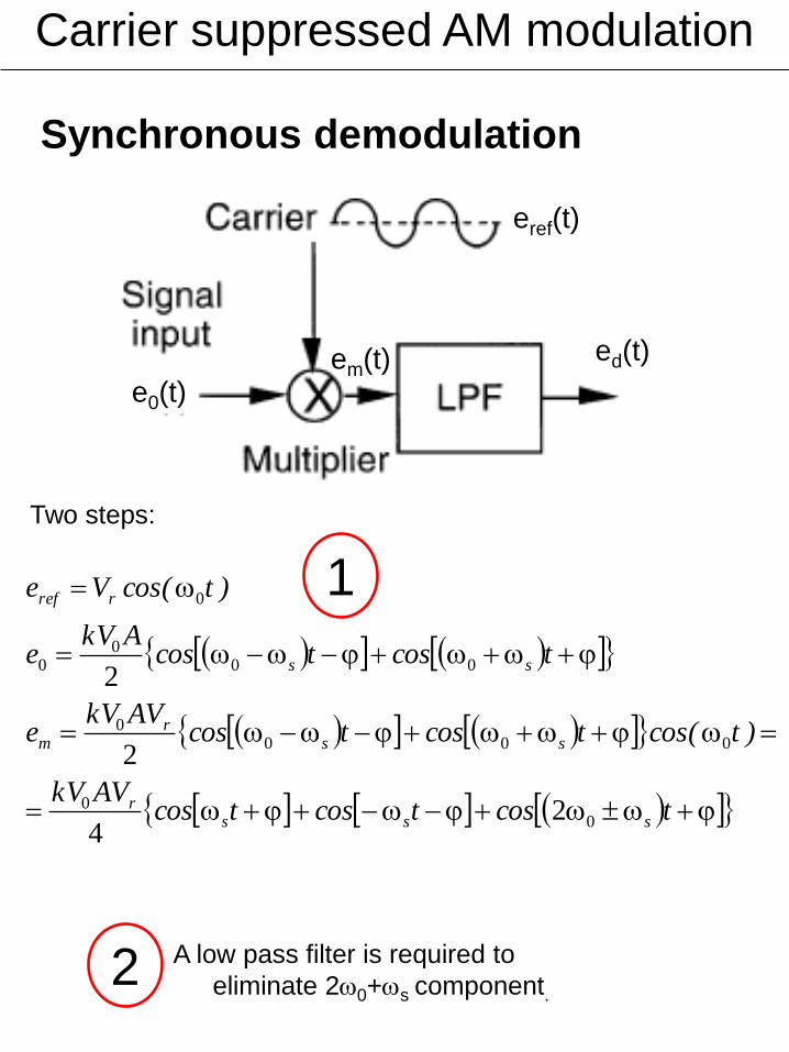
e0(t)
eref(t)
ed(t) em(t)
Synchronous demodulation
tcostcostcosAVkV
)tcos(tcostcosAVkV
e
tcostcosAkV
e
)tcos(Ve
sssr
ssr
m
ss
rref
00
0000
000
0
0
24
2
2
Two steps:
A low pass filter is required to
eliminate 20+s component.
Carrier suppressed AM modulation
1
2
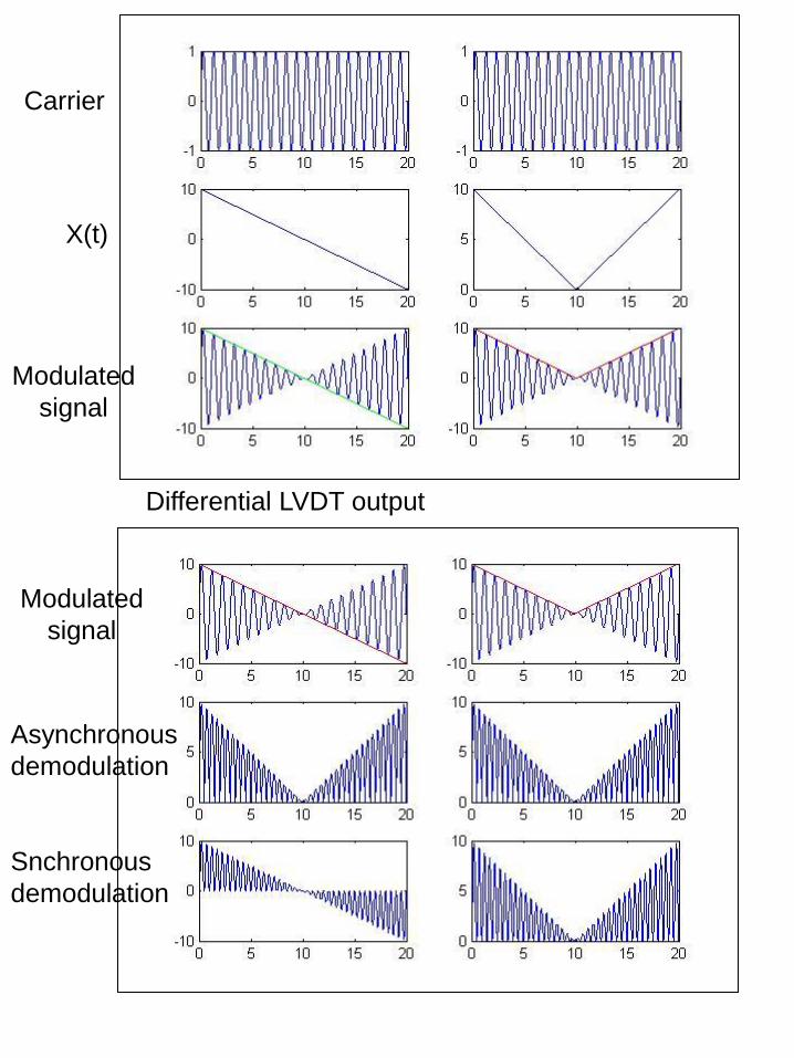
Differential LVDT output
Asynchronous
demodulation
Snchronous
demodulation
Carrier
X(t)
Modulated
signal
Modulated
signal

The Synchronous demodulation can
be implemented by a
CARRIER AMPLIFIER
Carrier suppressed AM modulation
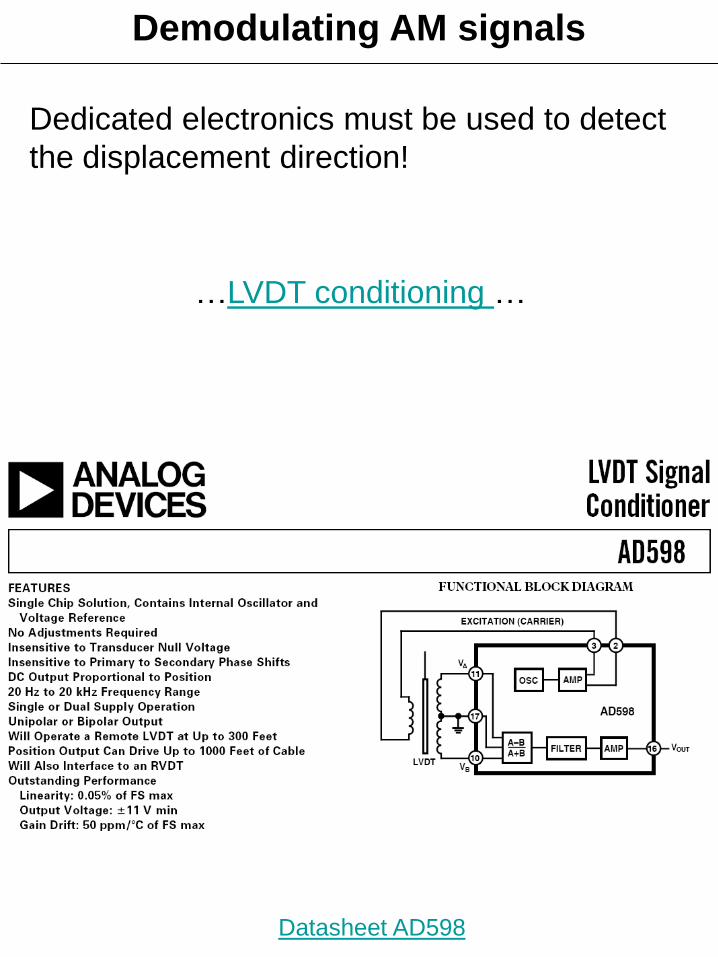
Dedicated electronics must be used to detect
the displacement direction!
Datasheet AD598
…LVDT conditioning …
Demodulating AM signals
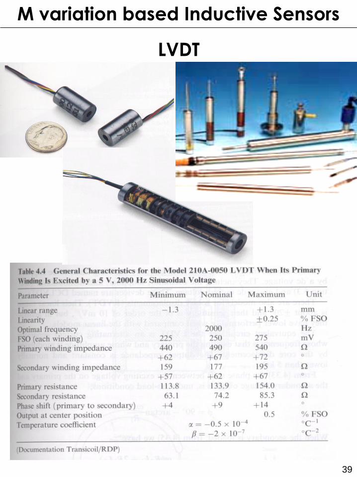
39
LVDT
M variation based Inductive Sensors
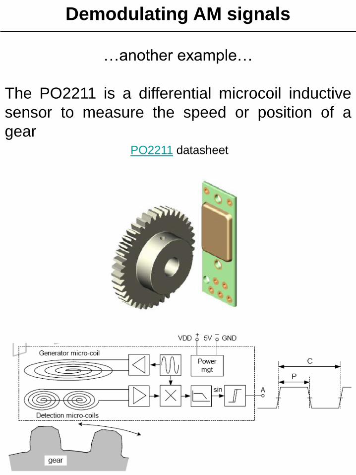
…another example…
The PO2211 is a differential microcoil inductive
sensor to measure the speed or position of a
gear PO2211 datasheet
Demodulating AM signals
41
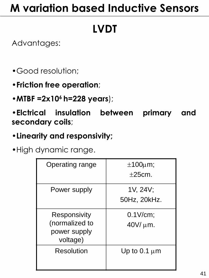
Advantages:
•Good resolution;
•Friction free operation;
•MTBF =2x10⁶ h=228 years);
•Elctrical insulation between primary and secondary coils;
•Linearity and responsivity;
•High dynamic range.
Operating range 100mm;
25cm.
Power supply 1V, 24V;
50Hz, 20kHz.
Responsivity
(normalized to
power supply
voltage)
0.1V/cm;
40V/ mm.
Resolution Up to 0.1 mm
LVDT
M variation based Inductive Sensors
42
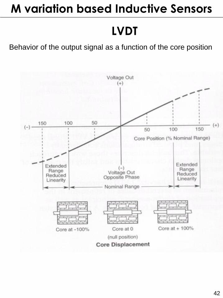
LVDT
Behavior of the output signal as a function of the core position
M variation based Inductive Sensors

43
Drawbacks
•Offset voltage in the null position due to
parasitic capacitance
•3° armonic distorsion due to the
ferromagnetic core saturation;
•Self heating of R.
LVDT
M variation based Inductive Sensors
44
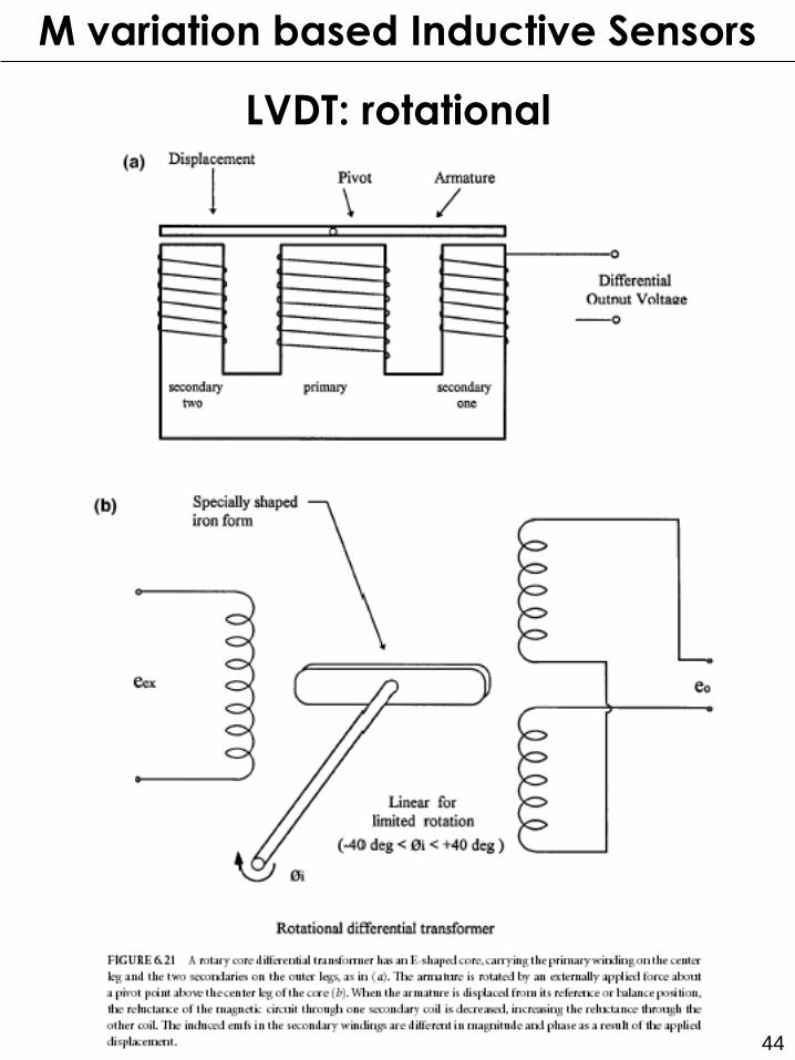
LVDT: rotational
M variation based Inductive Sensors
Related Documents