CPE 626 Advanced VLSI Design Lecture 2 Aleksandar Milenkovic http://www.ece.uah.edu/~milenka http://www.ece.uah.edu/~milenka/cpe626-04F/ [email protected] Assistant Professor Electrical and Computer Engineering Dept. University of Alabama in Huntsville

The Need for IP Cores
Jan 13, 2016
CPE 626 Advanced VLSI Design Lecture 2 Aleksandar Milenkovic http://www.ece.uah.edu/~milenka http://www.ece.uah.edu/~milenka/cpe626-04F/ [email protected] Assistant Professor Electrical and Computer Engineering Dept. University of Alabama in Huntsville. Benefits of HDL-based design - PowerPoint PPT Presentation
Welcome message from author
This document is posted to help you gain knowledge. Please leave a comment to let me know what you think about it! Share it to your friends and learn new things together.
Transcript
CPE 626 Advanced VLSI Design
Lecture 2
Aleksandar Milenkovic
http://www.ece.uah.edu/~milenkahttp://www.ece.uah.edu/~milenka/cpe626-04F/
Assistant ProfessorElectrical and Computer Engineering Dept.
University of Alabama in Huntsville

A. Milenkovic 2
Advanced VLSI Design
The Need for IP CoresBenefits of HDL-based design
Portability
Technology independence
Design cycle reduction
Automatic synthesis and Logic optimization
… But, the gap between available chip complexity and design productivity continues to increase
Design productivity21% / year
Chip Complexity 58% / year
Use IP cores
LaCASA IP Library

A. Milenkovic 3
Advanced VLSI Design
New Generation of Designers …Emphasis on hierarchical IP core design
Design systems, not components!
Understand hardware/software co-design
Understand and explore design tradeoffs between complexity, performance, and power consumption
Design a soft processor/micro-controller core
LaCASA IP Library

A. Milenkovic 4
Advanced VLSI Design
UAH Library of Soft Cores
Microchip’s PIC18 micro-controller
Microchip’s PIC16 micro-controller
Intel’s 8051
ARM Integer CPU core
FP10 Floating-point Unit (ARM)
Advanced Encryption Standard (AES)
Video Processing System on a Chip
LaCASA IP Library

A. Milenkovic 5
Advanced VLSI Design
Design Flow for CPU CoresReference Reference
ManualManual
InstructionInstructionSet AnalysisSet Analysis
Dpth&CntrDpth&CntrDesignDesign
VHDL ModelVHDL Model
VerificationVerification
ASM Test ASM Test ProgramsPrograms
MPLAB IDEMPLAB IDE
iHex2RomiHex2Rom
Synthesis&Synthesis&ImplementationImplementation
C C ProgramsPrograms
C CompilerC Compiler
LaCASA IP Library

A. Milenkovic 6
Advanced VLSI Design
Soft IP Engineering CycleEncompasses all relevant steps
Put together knowledge in digital design, HDLs, computer architecture, programming languages
State-of-the-art devices
Work in teams
Specification
Design
Modeling
Simulation &Verification
FPGA Implementation
Measurements(Compl.&Perf.&Power)
Design Improvements
LaCASA IP Library
A. Milenkovic 7
Advanced VLSI Design
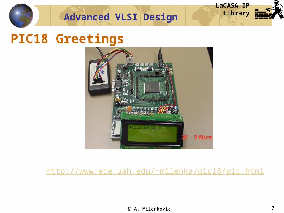
PIC18 Greetings
http://www.ece.uah.edu/~milenka/pic18/pic.html
LaCASA IP Library

A. Milenkovic 8
Advanced VLSI Design
Designing a simple CPU in 60 minutes
LaCASA step-by-step tutorialhttp://www.ece.uah.edu/~lacasa/tutorials/mu0/mu0tutorial.html
Design, verify, implement, and prototypea rudimentary processor MU0
Modeling using VHDL
Simulation using ModelSim
Implement using Xilinx ISE and a SpartanII device

A. Milenkovic 9
Advanced VLSI Design
MU0 – A Simple Processor
Instruction format
Instruction setopcode S
12 bits4 bits
Instruction Opcode Effect
LDA S 0000 ACC := mem16[S]
STO S 0001 mem16[S] := ACC
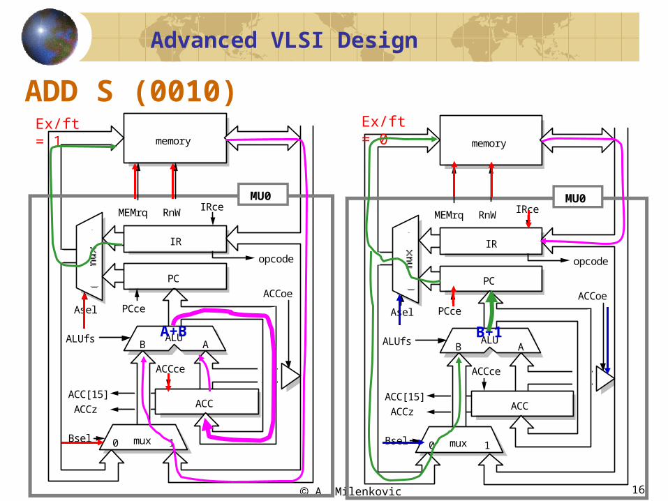
ADD S 0010 ACC := ACC + mem16[S]
SUB S 0011 ACC := ACC - mem16[S]
JMP S 0100 PC := S
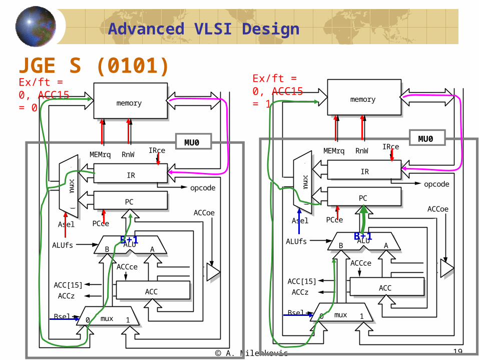
JGE S 0101 if ACC >= 0 PC := S
JNE S 0110 if ACC !=0 PC := S
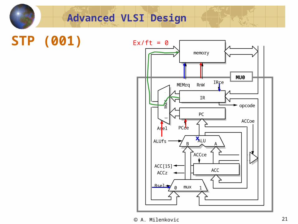
STP 0111 stop
A. Milenkovic 10
Advanced VLSI Design
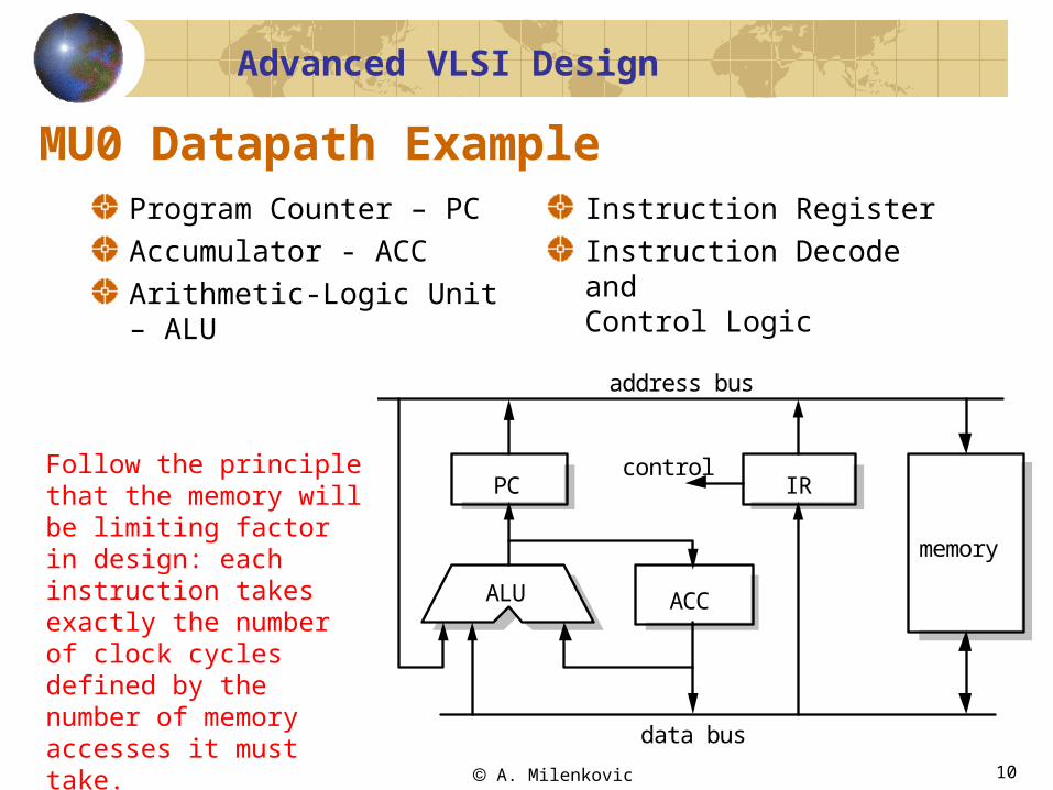
MU0 Datapath ExampleProgram Counter – PC
Accumulator - ACC
Arithmetic-Logic Unit – ALU
Instruction Register
Instruction Decode andControl Logic
IRPC
ACCALU
memory
control
address bus
data bus
Follow the principle that the memory will be limiting factor in design: each instruction takes exactly the number of clock cycles defined by the number of memory accesses it must take.

A. Milenkovic 11
Advanced VLSI Design
MU0 Datapath DesignAssume that each instruction starts when it has arrived in the IR
Step 1: EX (execute)LDA S: ACC <- Mem[S]
STO S: Mem[S] <- ACC
ADD S: ACC <- ACC + Mem[S]
SUB S: ACC <- ACC - Mem[S]
JMP S: PC <- S
JGE S: if (ACC >= 0) PC <- S
JNE S: if (ACC != 0) PC <- S
Step 2: IF (fetch the next instruction)
Either PC or the address in the IR is issued to fetch the next instruction
address is incremented in the ALU and value saved into the PC
InitializationReset input to start executing instructions from a known address; here it is 000hex
• provide zero at the ALU output and then load it into the PC register

A. Milenkovic 12
Advanced VLSI Design
MU0 RTL OrganizationControl Logic
Asel
Bsel
ACCce (ACC change enable)
PCce (PC change enable)
IRce (IR change enable)
ACCoe (ACC output enable)
ALUfs (ALU function select)
MEMrq (memory request)
RnW (read/write)
Ex/ft (execute/fetch)
memory
ACC
IRce
PCce
ALUfs
Bsel
ACCce
ACCoe
MEMrq RnW
mux0 1
Asel
ALUAB
PC
ACC[15]
ACCz
IR
opcode
MU0
A. Milenkovic 13
Advanced VLSI Design
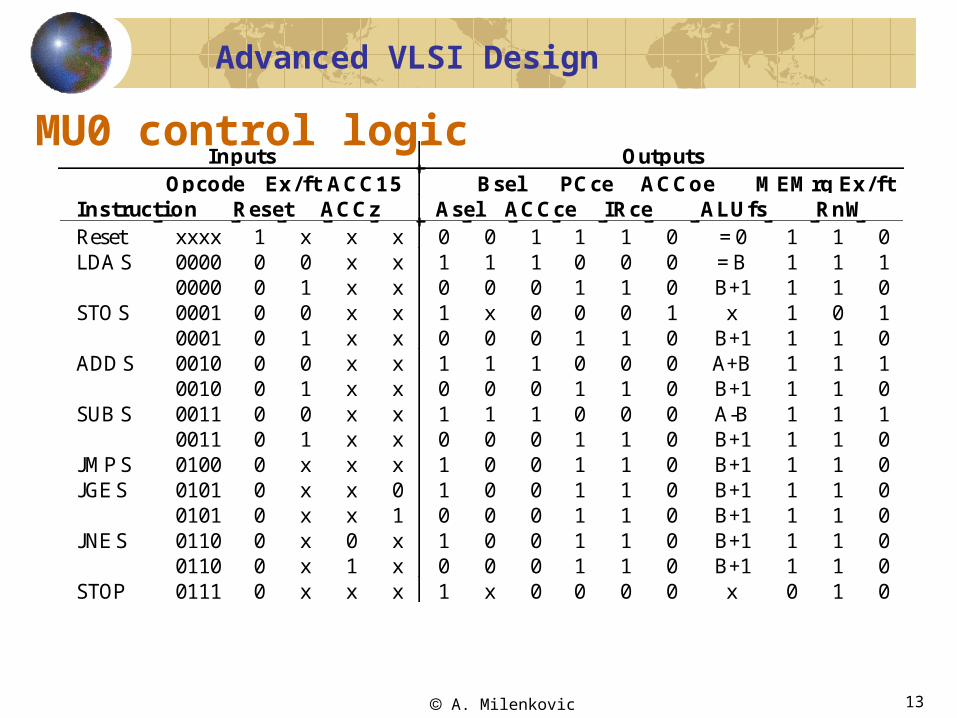
MU0 control logicInputs Outputs
Opco de Ex / f t ACC1 5 Bs e l PCce ACCo e MEMrq Ex / f tIns truct i o n Res et ACCz As el ACCce IRce ALUfs RnWReset xxxx 1 x x x 0 0 1 1 1 0 = 0 1 1 0LDA S 0000
000000
01
xx
xx
10
10
10
01
01
00
= BB+1
11
11
10
STO S 00010001
00
01
xx
xx
10
x0
00
01
01
10
xB+1
11
01
10
ADD S 00100010
00
01
xx
xx
10
10
10
01
01
00
A+BB+1
11
11
10
SUB S 00110011
00
01
xx
xx
10
10
10
01
01
00
A-BB+1
11
11
10
JMP S 0100 0 x x x 1 0 0 1 1 0 B+1 1 1 0JGE S 0101
010100
xx
xx
01
10
00
00
11
11
00
B+1B+1
11
11
00
JNE S 01100110
00
xx
01
xx
10
00
00
11
11
00
B+1B+1
11
11
00
STOP 0111 0 x x x 1 x 0 0 0 0 x 0 1 0

A. Milenkovic 14
Advanced VLSI Design
LDA S (0000)memory
ACC
IRce
PCce
ALUfs
Bsel
ACCce
ACCoe
MEMrq RnW
mux0 1
Asel
ALUAB
PC
ACC[15]
ACCz
IR
opcode
MU0
memory
ACC
IRce
PCce
ALUfs
Bsel
ACCce
ACCoe
MEMrq RnW
mux0 1
Asel
ALUAB
PC
ACC[15]
ACCz
IR
opcode
MU0
B
Ex/ft = 1Ex/ft = 0
B+1

A. Milenkovic 15
Advanced VLSI Design
STO S (0001)
memory
ACC
IRce
PCce
ALUfs
Bsel
ACCce
ACCoe
MEMrq RnW
mux0 1
Asel
ALUAB
PC
ACC[15]
ACCz
IR
opcode
MU0
memory
ACC
IRce
PCce
ALUfs
Bsel
ACCce
ACCoe
MEMrq RnW
mux0 1
Asel
ALUAB
PC
ACC[15]
ACCz
IR
opcode
MU0
x
Ex/ft = 1 Ex/ft = 0
B+1
A. Milenkovic 16
Advanced VLSI Design
ADD S (0010)
memory
ACC
IRce
PCce
ALUfs
Bsel
ACCce
ACCoe
MEMrq RnW
mux0 1
Asel
ALUAB
PC
ACC[15]
ACCz
IR
opcode
MU0
memory
ACC
IRce
PCce
ALUfs
Bsel
ACCce
ACCoe
MEMrq RnW
mux0 1
Asel
ALUAB
PC
ACC[15]
ACCz
IR
opcode
MU0
A+B
Ex/ft = 1 Ex/ft = 0
B+1

A. Milenkovic 17
Advanced VLSI Design
SUB S (0011)
memory
ACC
IRce
PCce
ALUfs
Bsel
ACCce
ACCoe
MEMrq RnW
mux0 1
Asel
ALUAB
PC
ACC[15]
ACCz
IR
opcode
MU0
memory
ACC
IRce
PCce
ALUfs
Bsel
ACCce
ACCoe
MEMrq RnW
mux0 1
Asel
ALUAB
PC
ACC[15]
ACCz
IR
opcode
MU0
A-B
Ex/ft = 1 Ex/ft = 0
B+1

A. Milenkovic 18
Advanced VLSI Design
JMP S (0100)memory
ACC
IRce
PCce
ALUfs
Bsel
ACCce
ACCoe
MEMrq RnW
mux0 1
Asel
ALUAB
PC
ACC[15]
ACCz
IR
opcode
MU0
B+1
Ex/ft = 0
A. Milenkovic 19
Advanced VLSI Design
JGE S (0101)
memory
ACC
IRce
PCce
ALUfs
Bsel
ACCce
ACCoe
MEMrq RnW
mux0 1
Asel
ALUAB
PC
ACC[15]
ACCz
IR
opcode
MU0
B+1
Ex/ft = 0, ACC15 = 0 memory
ACC
IRce
PCce
ALUfs
Bsel
ACCce
ACCoe
MEMrq RnW
mux0 1
Asel
ALUAB
PC
ACC[15]
ACCz
IR
opcode
MU0
B+1
Ex/ft = 0, ACC15 = 1

A. Milenkovic 20
Advanced VLSI Design
JNE S (0110)
memory
ACC
IRce
PCce
ALUfs
Bsel
ACCce
ACCoe
MEMrq RnW
mux0 1
Asel
ALUAB
PC
ACC[15]
ACCz
IR
opcode
MU0
B+1
Ex/ft = 0, ACCz = 0 memory
ACC
IRce
PCce
ALUfs
Bsel
ACCce
ACCoe
MEMrq RnW
mux0 1
Asel
ALUAB
PC
ACC[15]
ACCz
IR
opcode
MU0
B+1
Ex/ft = 0, ACCz = 1
A. Milenkovic 21
Advanced VLSI Design
STP (001)memory
ACC
IRce
PCce
ALUfs
Bsel
ACCce
ACCoe
MEMrq RnW
mux0 1
Asel
ALUAB
PC
ACC[15]
ACCz
IR
opcode
MU0
x
Ex/ft = 0

A. Milenkovic 22
Advanced VLSI Design
Resetmemory
ACC
IRce
PCce
ALUfs
Bsel
ACCce
ACCoe
MEMrq RnW
mux0 1
Asel
ALUAB
PC
ACC[15]
ACCz
IR
opcode
MU0
0
Ex/ft = 0
Related Documents


