NatVent Overcoming technical barriers to low-energy natural ventilation in office type buildings in moderate and cold climates EC CONTRACT: JOR3-CT95-0022 (DGXII) The NatVent programme 1.0 Fundamentals Charlotte Svensson J&W Consulting Engineers, Sweden Søren Aggerholm Danish Building Research Institute, SBI July 1998 Research part funded by THE EUROPEAN COMMISION in the framework of the Non Nuclear Energy Programme

Welcome message from author
This document is posted to help you gain knowledge. Please leave a comment to let me know what you think about it! Share it to your friends and learn new things together.
Transcript

NatVent
Overcoming technical barriers to low-energy
natural ventilation in office type buildings
in moderate and cold climates
EC CONTRACT: JOR3-CT95-0022 (DGXII)
The NatVent programme 1.0
Fundamentals
Charlotte Svensson
J&W Consulting Engineers, Sweden
Søren Aggerholm
Danish Building Research Institute, SBI
July 1998
Research part funded by
THE EUROPEAN COMMISION
in the framework of the
Non Nuclear Energy Programme

NatVentSimple Design Tool - Fundamentals
Contents
1 Infiltration, Ventilation and Thermal Modelling_______________________________ 3
2 Physical Fundamentals___________________________________________________ 4
2.1 Pressure distribution _______________________________________________________42.1.1 Wind Pressure __________________________________________________________42.1.2 Thermal Buoyancy ______________________________________________________52.1.3 Pressure difference ______________________________________________________6
2.2 Air Flows _________________________________________________________________72.2.1 General Air Flow Theory _________________________________________________72.2.2 Air Flow through the Building Envelope _____________________________________72.2.3 Air Flow through Vents___________________________________________________82.2.4 Air Flow through Windows________________________________________________82.2.5 Air Flow through Ducts___________________________________________________9
2.3 The Thermal Model _______________________________________________________112.3.1 General thermal theory __________________________________________________112.3.2 Transmission __________________________________________________________122.3.3 Clear sky solar radiation _________________________________________________132.3.4 Solar radiation on walls and roof __________________________________________152.3.5 Insolation through windows and skylight ____________________________________172.3.6 Internal Heat Gains _____________________________________________________192.3.7 Ventilation Cooling Power _______________________________________________19
2.4 Solution Method __________________________________________________________202.4.1 Introduction ___________________________________________________________202.4.2 System of Equations ____________________________________________________20
3 Nomenclature _________________________________________________________ 22
4 Acknowledgements _____________________________________________________ 24
5 Disclaimer ____________________________________________________________ 24
6 Future progress ________________________________________________________ 24
7 References ____________________________________________________________ 24
8 Appendix _____________________________________________________________ 25

Fundamentals - the NatVent simulation programme
Page 3
1 Infiltration, Ventilation and Thermal ModellingWith faster computers and better techniques of creating user-friendly interfaces it has becomepossible to write a programme, with a reasonable computing time for an ordinary PC, coupling athermal model with a ventilation model. It is also possible to make it user friendly so it can beavailable to everybody involved at the design stage. Our aims while developing this model have beento create a robust model with an easy-to-use interface and thus make the tool available to a largeaudience.
There are of cause other models in the area, both single-zone models and multi-zone models. AIDA -Air Infiltration Development Algorithm (Liddament, 1996) for example, is a basic single-zoneventilation and infiltration procedure. It is written in BASIC in about 50 lines but despite itssimplicity it is robust and incorporates most of the applicable physics.
More complex are the multi-zone models allowing to simulate the air flows between different roomsor zones within the building. Examples of programmes are the air flow models COMIS (Feustel &Raynoor, 1990) and CONTAM and the thermal models TSBI3 and TRNSYS. Some coupled modelswith one of these air flow models coupled with one of the thermal models have been made, e.g.COMIS and TRNSYS (Dorer and Weber 1994). These coupled programmes are large and acquirequite extensive input, which requires some work and knowledge from the user.
The NatVent programme is made to serve as a pre-design tool that can be used early in the designprocess before explicit data about the building and the ventilation system is known. Thereforeassumptions and simplifications about the building and the ventilation system are made within theprogramme.

Fundamentals - the NatVent simulation programme
Page 4
2 Physical FundamentalsIn this chapter the physical fundamentals of the programme are described. Due to a pressuredifference over the building envelope a force for the air flow is created. This gives the ventilationmodel. The thermal model encounters both indoor and outdoor effects on the thermal conditions. Thethermal and the ventilation models interacts and together they determine the indoor air temperatureand the ventilation rate.
2.1 Pressure distributionDue to wind, thermal buoyancy and fans, if any, a pressure difference over the building envelope willbe created. The different pressure differences caused by reasons above can be added and the totalpressure difference will vary over the facades and the roof. As a pressure difference occurs over thebuilding envelope, the air is bound to flow from higher pressure to lower pressure and thus air flow toand from the building will arise.
2.1.1 Wind PressureThe wind creates a pressure field around the building. The shape of this pressure field is determinedby the surroundings, the shape of the building and of cause by the wind velocity and direction.
The wind velocity varies with height and roughness of the surroundings. Wind velocities given in themeteorological input should be the wind velocity at a height of ten meters in open surroundings. Touse a value of the wind velocity that is appropriate for the specific conditions, the measured velocitymust be adjusted. In order to adjust the measured values to the current conditions, the programme usesthe empirical relation to determine the wind velocity at the height z, uz,wind:
u u k zz wind m wind waw
, ,= × × [m/s] (BS 5925 : 1991)
where: um,wind = measured wind velocity at 10 meters height [m/s]kw, aw = constants dependant on terrain [ - ] as in Table 2.1
Table 2.1: Classification of the shielding conditions
Description Shielding Conditions kw aw
Exposed Open, flat country 0.68 0.15Obstructions of 1/2 building’s height Country with scattered wind breads 0.52 0.2Obstructions of building’s height Urban 0.35 0.3
In the programme, the velocity is approximated to the velocity at the top of the building, and thus zequals the height of the building.
When the wind meets a facade the flow is slowed down on the wind ward side. The wind finds newpaths, as in Figure 2.1, and due to this a pressure pattern is developed with different pressures on thedifferent facade elements. The pressure varies for the different facades and also over a facade. Atypical pressure distribution over a building is presented in Figure 2.2.
Figure 2.1: Wind changing direction when meeting a facade
Fundamentals - the NatVent simulation programme
Page 5
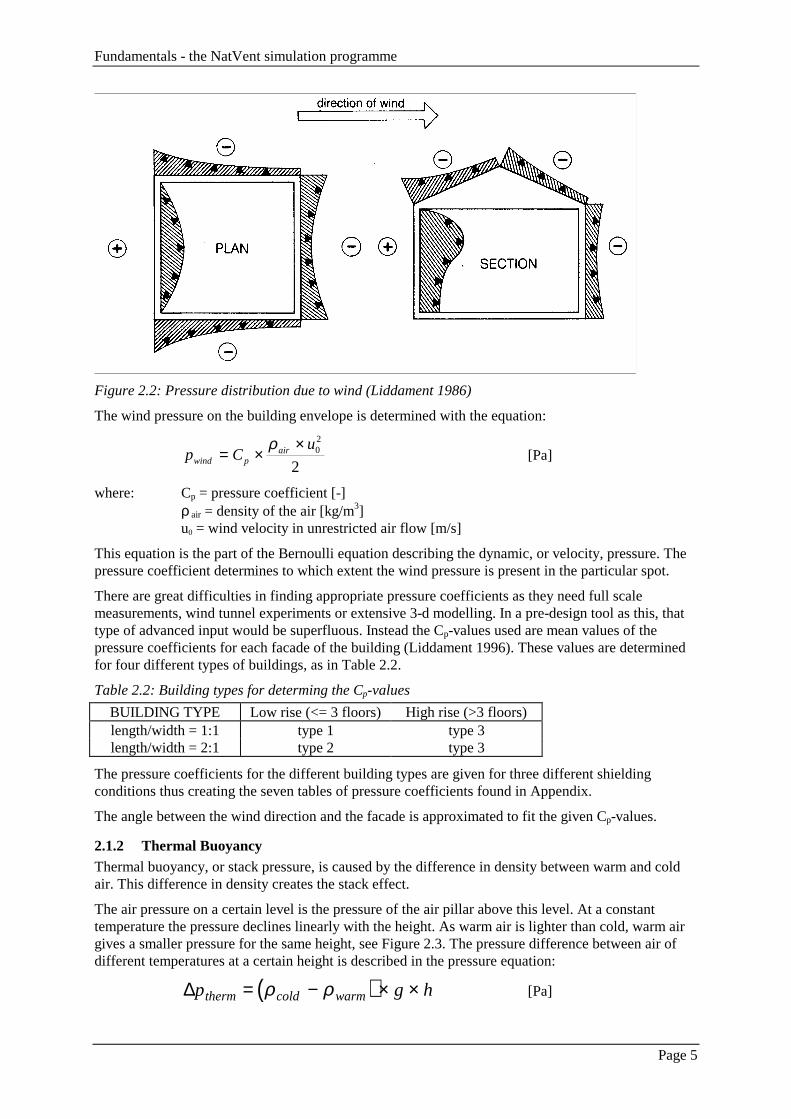
Figure 2.2: Pressure distribution due to wind (Liddament 1986)
The wind pressure on the building envelope is determined with the equation:
p Cu
wind pair= ×
×ρ 02
2[Pa]
where: Cp = pressure coefficient [-]ρ air = density of the air [kg/m3]u0 = wind velocity in unrestricted air flow [m/s]
This equation is the part of the Bernoulli equation describing the dynamic, or velocity, pressure. Thepressure coefficient determines to which extent the wind pressure is present in the particular spot.
There are great difficulties in finding appropriate pressure coefficients as they need full scalemeasurements, wind tunnel experiments or extensive 3-d modelling. In a pre-design tool as this, thattype of advanced input would be superfluous. Instead the Cp-values used are mean values of thepressure coefficients for each facade of the building (Liddament 1996). These values are determinedfor four different types of buildings, as in Table 2.2.
Table 2.2: Building types for determing the Cp-values
BUILDING TYPE Low rise (<= 3 floors) High rise (>3 floors)length/width = 1:1 type 1 type 3length/width = 2:1 type 2 type 3
The pressure coefficients for the different building types are given for three different shieldingconditions thus creating the seven tables of pressure coefficients found in Appendix.
The angle between the wind direction and the facade is approximated to fit the given Cp-values.
2.1.2 Thermal BuoyancyThermal buoyancy, or stack pressure, is caused by the difference in density between warm and coldair. This difference in density creates the stack effect.
The air pressure on a certain level is the pressure of the air pillar above this level. At a constanttemperature the pressure declines linearly with the height. As warm air is lighter than cold, warm airgives a smaller pressure for the same height, see Figure 2.3. The pressure difference between air ofdifferent temperatures at a certain height is described in the pressure equation:
( )∆p g htherm cold warm= − × ×ρ ρ [Pa]

Fundamentals - the NatVent simulation programme
Page 6
where: ρcold = density of the colder air [kg/m3]ρwarm = density of the warmer air [kg/m3]g = gravitation = 9.81 [m/s2]h = height [m]
p0 p0 ∆p = 0
p g hwarm0 + × ×ρ p g hcold0 + × ×ρ ( )∆p g hcold warm= − × ×ρ ρFigure 2.3: Pressure differences due to thermal buoyancy
The density of air is affected by the temperature and the moisture content of the air. The density of airat the temperature zero degrees Celsius and a relative humidity of 50 % is 1.291 kg/m3. The density atother temperatures can be derived from this.
During the heating season the indoor air is warmer than the outdoor air and this gives a natural drivingforce for the air.
When the pressure due to thermal buoyancy is determined the reference height, href = 0, is set toground level.
In a large volume a certain temperature stratification will occur. This is not considered in theprogramme.
The effect on air density of the moisture content in the air is quite small especially for the moderatetemperature interval (about -20ºC - +40ºC) the programme is dealing with. Therefore the effect ofdifferent relative humidities is neglected in the programme. The relative humidity used in theprogramme is 50 %.
As the NatVent programme is dealing primarily with naturally ventilated buildings, fans are no bigissue for the programme. Radial fans can be simulated as a steady flow rate which is added in themass balance. If the fans are running only non-working hours, i.e. for night cooling, the programmeassumes that they are only running if the calculated internal mean temperature for the last 24 hoursexceeds 20 degrees Celsius.
2.1.3 Pressure differenceThe pressure difference over the building envelope due to wind and thermal buoyancy can be addedand, with stating an internal pressure, a total pressure difference over the building envelope can befound.
∆ ∆p p p ptot wind therm= + + int [Pa]
where: pint = internal pressure at ground level [Pa]

Fundamentals - the NatVent simulation programme
Page 7
2.2 Air Flows
2.2.1 General Air Flow TheoryAir flow through the building envelope can take many paths. Air flow through walls and ceiling,through small cracks and imperfections, through vents in the facade, through window airing, throughskylight, through ducts for supply air or passive stacks and forced flow through fans - if any. In orderto get a realistic model of the building, it is of importance that the paths are described in a realisticway.
The pressure drop over a crack due to the air flow through cracks, small openings etc, is generallydescribed with the equation (Kronvall, 1980):
∆pl
d
ucrack fric
crack
hi
i
nair m= × +
×
×
=∑λ ξ ρ
1
2
2[Pa]
where: λfric = friction coefficient [ - ]lcrack = length in flow direction [m]dh = hydraulic diameter [m]ξi = loss factor, for contraction, expansion or bend losses [ - ]ρair = density of the air [kg/m3]um = average air velocity [m/s]
The friction factor is dependant on the surface roughness and Reynolds’ number, Re. Whether the airflow can be described as laminar or turbulent is determined by Reynolds’ number:
Re=×u dm h
ν [ - ]
where: ν = η / ρ = the kinematic viscosity [m2/s]
The kinematic viscosity is slightly temperature dependant as the viscosity and the density aretemperature dependant. The viscosity in the flow path is calculated with:
( )ηcrack crackT= + × × −171 0 049 106. . [Ns/ m2]
where: Tcrack = air temperature in the flow path [°C]
If the Reynolds’s number is larger than about 3500 the air flow is turbulent and if it is smaller thanabout 2300 it is laminar. In the interval 2300 - 3500 the flow is a mix between turbulent and laminarflow.
To simplify the equations above and to summarise all pressure drops along the flow path, the air flowrate is presented as the equation:
q a pmb= × ∆ [kg/s]
where: a = flow coefficient [kg / (s*Pab)]b = flow exponent [-]
2.2.2 Air Flow through the Building EnvelopeTo mathematically describe the air flow through the building envelope is difficult as the air flow runthrough both porous materials and through leaks and imperfections in the facade.
A flow exponent of 0.67 is assumed, since it is emperical shown by many measurements on buildingenvelopes that this is a good estimation.
The air flow equation from 2.2.1 is used and the programme assumes the flow exponent to 0.67,
q a pm = × ∆ 0 67. [kg/s]
Fundamentals - the NatVent simulation programme
Page 8
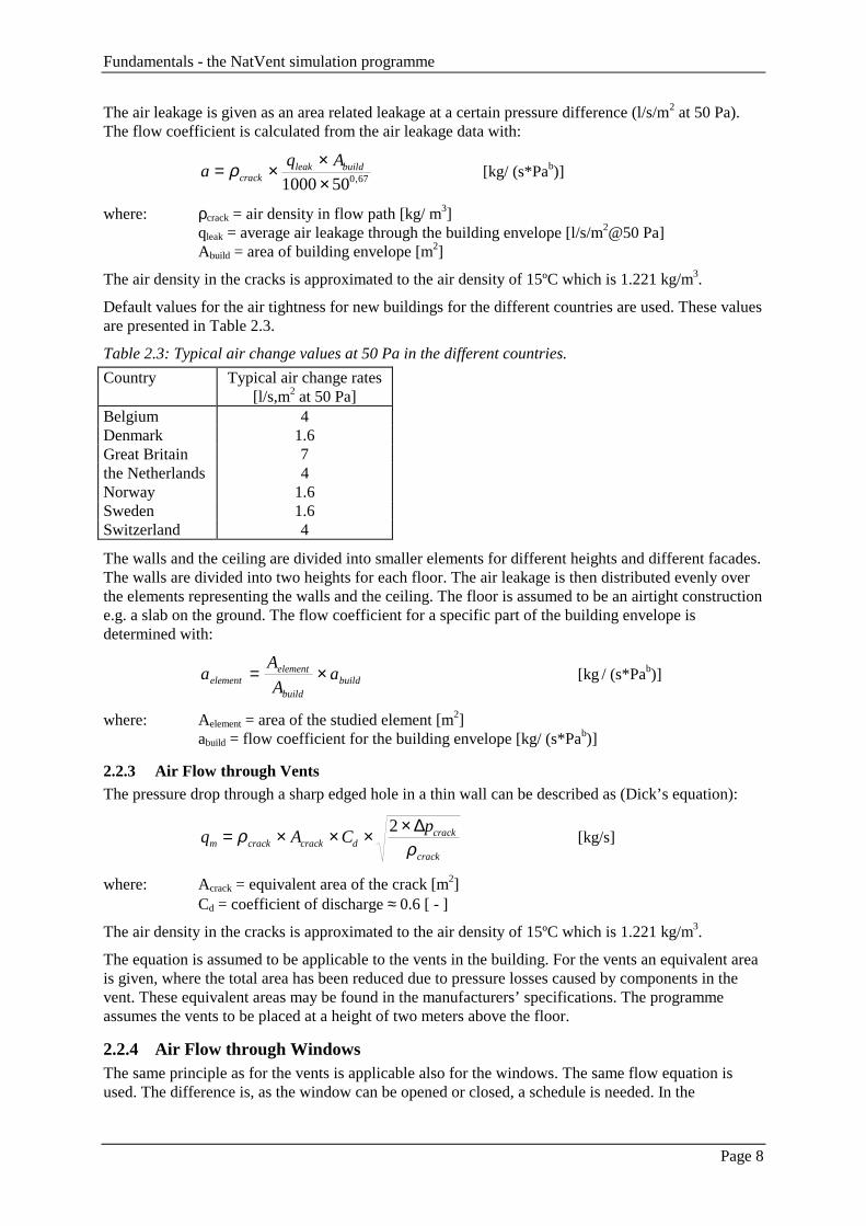
The air leakage is given as an area related leakage at a certain pressure difference (l/s/m2 at 50 Pa).The flow coefficient is calculated from the air leakage data with:
aq A
crackleak build= × ×
×ρ
1000 500 67, [kg/ (s*Pab)]
where: ρcrack = air density in flow path [kg/ m3]qleak = average air leakage through the building envelope [l/s/m2@50 Pa]Abuild = area of building envelope [m2]
The air density in the cracks is approximated to the air density of 15ºC which is 1.221 kg/m3.
Default values for the air tightness for new buildings for the different countries are used. These valuesare presented in Table 2.3.
Table 2.3: Typical air change values at 50 Pa in the different countries.
Country Typical air change rates[l/s,m2 at 50 Pa]
Belgium 4Denmark 1.6Great Britain 7the Netherlands 4Norway 1.6Sweden 1.6Switzerland 4
The walls and the ceiling are divided into smaller elements for different heights and different facades.The walls are divided into two heights for each floor. The air leakage is then distributed evenly overthe elements representing the walls and the ceiling. The floor is assumed to be an airtight constructione.g. a slab on the ground. The flow coefficient for a specific part of the building envelope isdetermined with:
aA
Aaelement
element
buildbuild= × [kg / (s*Pab)]
where: Aelement = area of the studied element [m2]abuild = flow coefficient for the building envelope [kg/ (s*Pab)]
2.2.3 Air Flow through VentsThe pressure drop through a sharp edged hole in a thin wall can be described as (Dick’s equation):
q A Cp
m crack crack dcrack
crack
= × × × ×ρρ
2 ∆[kg/s]
where: Acrack = equivalent area of the crack [m2]Cd = coefficient of discharge ≈ 0.6 [ - ]
The air density in the cracks is approximated to the air density of 15ºC which is 1.221 kg/m3.
The equation is assumed to be applicable to the vents in the building. For the vents an equivalent areais given, where the total area has been reduced due to pressure losses caused by components in thevent. These equivalent areas may be found in the manufacturers’ specifications. The programmeassumes the vents to be placed at a height of two meters above the floor.
2.2.4 Air Flow through WindowsThe same principle as for the vents is applicable also for the windows. The same flow equation isused. The difference is, as the window can be opened or closed, a schedule is needed. In the

Fundamentals - the NatVent simulation programme
Page 9
programme the windows are open (ajar) during working hours and closed during the night. If thewindows are open day and night they should be simulated as vents, with an equivalent open area.
A large opening such as a window may have air flow that differs in direction top to bottom. To enablethe option of a two way flow through the window, it is simulated as two links, one bottom half andone top half. From the given top and bottom frame heights, the two links representing the window isapproximated. Figure 2.4 shows how a window is simulated.
Figure 2.4: The heights to the left in the two figures are the heights given. The heights to the right arethe calculated link heights.
In order to describe a window which is ajar, the opening factor, the portion open of the window, isintroduced and the equivalent area of the open window is:
( ) ( )A t o t Aopenwindow window totopenwindow= × [kg/s]
where: owindow = opening factor for the window, 0 < owindow < 1 [-]Atotopenwindow = total area of open windows [m2]
If the opening factor is 0 the window is closed and if it is 1 it is fully open. In between anapproximation of the open portion of the window has to be made.
The programme assumes owindow = 0.1 which is an approximation of a window which is ajar.
If an entire year is studied, the ventilation strategy is determined by the calculated internaltemperature. If the calculated internal temperature exceeds 20ºC, the windows are opened, as given inthe input, during working hours. If the calculated temperature is below this temperature the windowsare closed.
2.2.5 Air Flow through DuctsThere are two kind of ducts: supply air ducts and passive stacks. They both include air flow throughducts and they are treated in similar ways. The flow through the ducts is determined with theequation:
q a pmb= × ∆ [kg/s]
where: b = flow exponent, assumed value 0.5 [-]
In the ducts the total pressure drop is due to friction losses along the duct and to losses due tocomponents.
( )∆ ∆ Σ ∆p p pduct friction component= + [Pa]
where: ∆pfriction = pressure loss due to friction [Pa]

Fundamentals - the NatVent simulation programme
Page 10
∆pcomponent = pressure loss due to components [Pa]
As the components in the system are unknown, the component pressure drop is approximated as to thepressure drop of a circular hole (see 2.2.3). The friction part of the pressure drop over the ducts isstudied.
∆pl
d
ufriction fric
duct
h
air m= × ××λ ρ 2
2[Pa]
where: lduct = length in flow direction [m]
By transforming the average air velocity into a flow rate, this equation can be written on the generalform with the flow coefficient due to friction is:
a Ad
lfriction duct ducth
fric duct air
= ××
× ×ρ
λ ρ2
[kg / (s*Pab)]
The friction factor is approximated with (Selander, 1978):
λ ε εfric
h hd d= × − × + ×
+
−
24 793 10
0 2 0 2698
2
log.
Relog
Re. . [ - ]
where: ε = surface roughness, assumed value = 0.15 (Kronvall, 1980) [mm]
For the ducts the hydraulic diameter is given by the size of the duct. The programme assumes a size ofthe stacks and the ducts that give a hydraulic diameter for the passive stacks of 0.2 m and for thesupply air ducts of 0.5 m.
Reynolds’ numbers are calculated as in 2.2.1, with the air density and the kinematic viscositydetermined at the average temperature. The air velocity used is the velocity of the previous time step,i.e. um(time-1).
When the component losses are described as a hole an equation can be formulated:
q
a
q
a
q
aduct
duct
friction
friction
crack
crack
= + [Pa]
where: qduct = qfriction = qcrack = the flow through the duct [kg/s]
As the flow through the sharp edged hole is the same as the flow through the duct, the flow coefficientfor the duct can be determined from the flow coefficients of the two pressure losses:
a
a a
duct
friction crack
=
+
1
1 12 2
[kg / (s*Pab)]

Fundamentals - the NatVent simulation programme
Page 11
2.3 The Thermal ModelThe thermal conditions are of most interest during the summer period as during the heating season theindoor air temperature, as well as the internal surface temperature, are assumed to be kept at aminimum of 20 °C by the heating system, see 2.3.1.
2.3.1 General thermal theoryThe heat balance and the indoor temperature are calculated hour by hour using a one time constantmodel, see Figure 2.5. In the model it is assumed that all internal structures and surfaces have thesame temperature. The heat balance and the indoor air temperature calculated are an average for thebuilding or the zone.
φs,window,i
φs,roof
φs,wall,i
• TstrucTsurf •Tair
•
φin
Text
Figure 2.5: The thermal model.
The heat transferred to the indoor air is calculated first - neglecting the heat exchange between theinternal surfaces and the indoor air:
Φ Φ Φ Φ Φair in s window window vent= × + × + +05 05. . , [W]
where: Φin = internal heat gains [W]Φs,window = insolation through the skylight and the windows [W]Φwindow = heat transfer through the skylight and the windows, excl. solar radiation [W]Φvent = heat transfer by ventilation [W]
The new indoor air temperature at time t is calculated using the internal surface temperature from theprevious time step:
( )T t T t tHair surf
air
a s
= − +−
( )∆ Φ[°C]
where: Tsurf(t-∆t) = internal surface temperature at the previous time step [C°]∆t = length of each time step [s]Φair = heat transfer to the indoor air (neglecting heat exchange with surfaces) [W]Ha-s = specific heat transfer between indoor air and internal surfaces [W/K]
The specific heat transfer between the indoor air and the internal surfaces are:

Fundamentals - the NatVent simulation programme
Page 12
floorsa AhH ××=− int4 [W/K]
where: hint = internal surface heat transfer coefficient [W/m2 K]Afloor = gross floor area in the building or zone [m2]
The programme anticipates an internal surface to gross floor area ratio of 4 and an internal surface toair heat transfer coefficient hint = 3 W/m2 K.
The heat transfer from the indoor air to the internal surfaces is then:
( ) ( )( )ttTtTH airairsasa ∆−−×=Φ −− [W]
The new internal surface temperature is calculated from the internal surface temperature at theprevious time step.
( ) ( )T t T t t tCsurf surf
surf
struc
= − + ×∆ ∆Φ
[°C]
where: Φsurf = resultant heat transfer to internal surfaces [W]Cstruc = active thermal capacity of structures in the building [Wh/K]
The active thermal capacity in buildings with different types of structures is shown in Table 2.4.
The resultant heat transferred to the internal surfaces is:
Φ Φ Φ Φ Φ Φsurf in s window s wall wall a s= × + × + + + −05 05. . , , [W]
where: Φin = internal heat gains [W]Φs,window = insolation through the skylight and the windows [W]Φs,wall = solar energy transmitted through roof and walls to internal surfaces [W]Φwall = heat transfer through roof and walls, excluding solar radiation [W]Φa-s = heat transfer from indoor air to internal surfaces [W]
The thermal model is only used in the summer for the calculation of the indoor air temperature andthe internal surface temperature in the building. In winter the indoor air temperature and the internalsurface temperature is set to 20 degrees Celsius and the thermal model is not used.
During the year-round performance a minimum indoor air temperature and a minimum internalsurface temperature of 18 °C during working hours and 17 °C during non-working hours are used ifthe minimum air temperature during the past 24 hours is below 22 °C.
Table 2.4: Active thermal capacity of structures per m2 gross floor area.Description Internal Construction Active Thermal Capacity, cstruc
Wh/K m2
Very Light Light walls, floor and ceiling, e.g. skeleton withboards, without any heavy structures.
40
Light Some heavy structures, e.g. concrete slab withwooden floor or light-weight concrete walls.
80
Heavy Several heavy structures, e.g. concrete slab withclinker and brick or clinker concrete walls.
120
Very Heavy Heavy walls, floor and ceiling made byconcrete, brick or clinker.
160
2.3.2 TransmissionU-values for external walls, roof and windows are calculated from the insulation thickness or suppliedby the user of the programme. Heat losses through the ground floor is set to 0. Heat losses from thebuilding are indicated by negative numbers.

Fundamentals - the NatVent simulation programme
Page 13
The heat transfer through the roof and the external walls is (excluding solar radiation):
( ) ( )( )ttTtTH surfextwallwall ∆−−×=Φ [W]
and the heat transfer through the skylight and the windows is:
( ) ( )( )ttTtTH airextwindowwindow ∆−−×=Φ [W]
where: Text(t) = external air temperature [°C]Tsurf(t-∆t) = internal surface temperature at the previous time step [°C]Tair(t-∆t) = indoor air temperature at the previous time step [°C]Hwall = specific heat transfer through roof and walls from ext. air to int. surfaces [W/K]Hwindow = spec. heat trans. through skylight and windows from ext. to indoor air [W/K]
The specific heat transfer through the external walls and the roof from the external air to the internalsurfaces is:
( )∑=
−− ×+×=4
1,,,
facadesewalliwallseroofroofwall UAUAH [W/K]
and the specific heat transfer through the skylight and the windows is:
( )∑=
×+×=4
1,
facadewindowiwindowwindowskylightwindow UAUAH [W/K]
where: Aroof = roof area [m2]Awall,i = external wall area of facade i [m2]Askylight = skylight area, measured as the hole in the roof [m2]Awindow,i = window area in facade i [m2]Uroof,e-s = U-Value between external air and internal surface for the roof [W/m2 K]Uwall,e-s = U-Value between external air and internal surface for the walls [W/m2 K]Uwindow = U-Value for the windows [W/m2 K]
The U-value between the external air and the internal surface of the construction is:
U
h U
e s
ext s s
−
−
=+
11 1
[W/m2 K]
where: hext = external surface heat transfer coefficient [W/m2 K]Us-s = U-value between external surface and internal surface [W/m2 K]
In the programme an external surface heat transfer coefficient of 10 W/m2 K is anticipated at summerconditions.
2.3.3 Clear sky solar radiationFor summer design the solar radiation is calculated assuming clear sky, see Figure 2.6.

Fundamentals - the NatVent simulation programme
Page 14
Eo
Eeo
ED,n
Ed,h
Figure 2.6: Generation of solar radiation weather data for clear sky conditions.
The extraterrestial irradiance is:
××+×=
365
360cos033.01
JEE oeo [W/m2]
where: Eo = solar constant [W/m2]J = day of year (1 = January 1. and 365 = December 31.)
The programme anticipates Eo = 1377 W/m2.
The direct solar radiation normal to the beam at ground level is:
≤
>
+××−×=
00
04.99.0
exp,
s
seonD
if
ifm
BmE
Eγ
γ[W/m2]
where: γs = altitude of the sun above the horizon [deg.]m = relative optical air mass [ - ]B = turbidity coefficient [ - ]
The programme uses a turbidity coefficient B = 3.5, anticipating sub-urban location and summerconditions.
The relative optical air mass is:
ms
= 1
sinγ[ - ]
The diffuse solar radiation on the horizontal plane at ground level is:
( )
≤>×−×
=00
0sin,,
s
ssnDeohd if
ifEEE
γγγκ
[W/m2]
The constant κ is the ratio between the diffuse solar radiation on the horizontal plane at ground leveland the total diffuse scattering of the solar radiation as it passes through the atmosphere. Theprogramme anticipates a constant κ = 0.28.The solar radiation on external surfaces and the insolation through windows is then calculated fromthis, see Figure 2.7.

Fundamentals - the NatVent simulation programme
Page 15
ED,n
Ed,h
φs,wall,i
φs,window,i
φs,roof
φs,skylight
Figure 2.7: Calculation of solar radiation on external surfaces and insolation through windows.
2.3.4 Solar radiation on walls and roofThe direct solar radiation on the horizontal plane and therefore also on the roof is:
≤>×
=00
0sin,,
s
ssnDhD if
ifEE
γγγ
[W/m2]
where: ED,n = direct solar radiation normal to the beam at ground level [W/m2]
The direct solar radiation on wall i is:
≥≤<>⋅
=900
90cos
,
,,,,,
iwallhs
iwallhsiwallnDiwallD iorif
iandifiEE
γγγγ
[W/m2]
where: γh = horizon angle [deg.]γs = altitude of the sun above the horizon, [deg.]iwall,i = incidence angle for direct solar radiation on wall i, [deg.]
The horizon angle, γh is the average altitude angle to the top of the surroundings: ground, buildings,trees etc., see Table 2.5.
Table 2.5: Horizon angle, γh. Average of all windows in the facades of the building. The distance tothe obstructions are assumed to be equal to the height of the building.Surroundings Horizon angle, γh
Deg.Free horizon 0Buildings or trees with 1/2 the height of the building 10Buildings or trees with the same height as the building 25
The angle is measured from the centre of the facade, see Figure 2.8. The same angel is anticipated forall windows in the facade.
Figure 2.8: Definition of horizon angle γh.

Fundamentals - the NatVent simulation programme
Page 16
The incidence angle is measured between the solar radiation beam and the normal to the wall. Theangle is calculated as:
( )( )iwallssiwalli ,, coscosarccos ααγ −×= [deg.]
where: αs = solar azimuth angle [deg.]αwall,i = azimuth angle of the normal to the wall [deg.]
Both azimuth angles are angular displacement from south measured on the horizontal plane.
The diffuse solar radiation on wall i is:
E f Ed wall i cl wall i d h, , , , ,= ⋅ [W/m2]
where: fcl,wall,i = diffuse solar radiation factor for wall i for clear sky conditions [-]
The diffuse solar radiation factor, fcl,wall,i is the diffuse solar radiation on the (vertical) wall comparedto the diffuse solar radiation on the horizontal plane. The diffuse solar radiation factor is:
<×+≥×+×+
=0coscos1.065.0
0coscos45.0cos2.065.0
,,
,,2
,,,
iwalliwall
iwalliwalliwalliwallcl iifi
iifiif [ - ]
The solar radiation on the walls from the ground reflectans is the same for all the walls:
( )hdhDwallr EErE ,,, 5.0 +××= [W/m2]
where: r = reflectance of the ground [ - ]Ed,h = diffuse solar radiation on the horizontal plane at ground level [W/m2]
The programme anticipates r = 0.20 .
The solar radiation on the roof is:
φ s roof D h d hE E, , ,= + [W/m2]
and the solar radiation on wall i is:
φ s wall i D wall i d wall i r wallE E E, , , , , , ,= + + [W/m2]
The total solar energy transmitted through the roof and the walls is:
( )∑=
××+××=Φ4
1,,,,,
facadeiwallwalliwallsroofroofroofswalls AA ηφηφ [W]
where: ηroof = solar transmission factor for the roof [ - ]Aroof = roof area [m2]ηwall = solar transmission factor for the external walls [ - ]Awall,i = external wall in facade i [m2]
The solar transmission factor for the roof is:
ssroofext
ssroofroofroof Uh
U
−
−
+⋅
=,
,αη
and the solar transmission factor for the external walls is:
sswallext
sswallwallwall Uh
U
−
−
+⋅
=,
,αη
Fundamentals - the NatVent simulation programme
Page 17
where: αroof = solar absorptance for the roof [ - ]αwall = solar absorptance for the walls [ - ]Uroof,s-s = U-value between external roof surface and internal roof surface [W/m2 K]Uwall,s-s = U-value between external wall surface and internal wall surface [W/m2 K]hext = external surface heat transfer coefficient [W/m2 K]
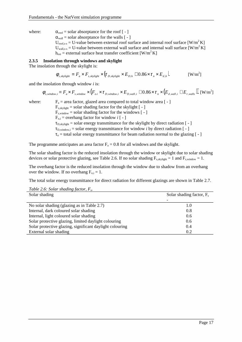
2.3.5 Insolation through windows and skylightThe insolation through the skylight is:
( )hdnhDskylightDskylightsaskylights EEFF ,,,,, 86.0 ××+×××= ττφ [W/m2]
and the insolation through window i is:
( )( )wallsriwalldniwallDiwindowDiowindowsaiwindows EEEFFF ,,,,,,,.,,, 86.0 +××+××××= ττφ [W/m2]
where: Fa = area factor, glazed area compared to total window area [ - ]Fs,skylight = solar shading factor for the skylight [ - ]Fs,window = solar shading factor for the windows [ - ]Fo,i = overhang factor for window i [ - ]τD,skylight = solar energy transmittance for the skylight by direct radiation [ - ]τD,window,i = solar energy transmittance for window i by direct radiation [ - ]τn = total solar energy transmittance for beam radiation normal to the glazing [ - ]
The programme anticipates an area factor Fa = 0.8 for all windows and the skylight.
The solar shading factor is the reduced insolation through the window or skylight due to solar shadingdevices or solar protective glazing, see Table 2.6. If no solar shading Fs,skylight = 1 and Fs,window = 1.
The overhang factor is the reduced insolation through the window due to shadow from an overhangover the window. If no overhang Fo,i = 1.
The total solar energy transmittance for direct radiation for different glazings are shown in Table 2.7.
Table 2.6: Solar shading factor, Fs.Solar shading Solar shading factor, Fs
-No solar shading (glazing as in Table 2.7) 1.0Internal, dark coloured solar shading 0.8Internal, light coloured solar shading 0.6Solar protective glazing, limited daylight colouring 0.6Solar protective glazing, significant daylight colouring 0.4External solar shading 0.2

Fundamentals - the NatVent simulation programme
Page 18
Table 2.7: Characteristics of glazing.Glazing U-value glazing
W/m2 KU-value windowW/m2 K
Transmittance, τn
-Single panes 6.0 5.0 0.85Double panes 3.0 2.7 0.75Triple panes 2.0 1.9 0.65Energy panes (double panes with argon
filling and one low emission coating)1.6 1.6 0.65
The overhang factor for window i is calculated as:
( ) ( )( )
≤−
>−×−
×−=
0cos0
0costancos
tan5.01
,
,,.,,
iwallls
iwalllsioiwalls
s
io
if
ifF
αα
ααεαα
γ[ - ]
where: γs = altitude of the sun above the horizon [deg.]αs = solar azimuth angle [deg.]αwall,i = azimuth angle of the normal to wall i [deg.]εo,i = overhang angle for window i [deg.]
The overhang angle is the zenith angle measured from the centre of the window to the front ofoverhang, see Figure 2.9. The programme uses the overhang angles shown in Table 2.8.
Figure 2.9: Definition of overhang.
Table 2.8: Overhang angle, εo,i. Zenith angle, measured from the centre of the window to the front ofthe overhang.Overhang Overhang angle, εo,i
Deg.No overhang 0Small overhang 20Medium overhang 40Large overhang 60
The solar energy transmittance for the skylight by direct radiation is calculated as:
≤
>
−
⋅+
−
⋅−−
⋅−⋅=00
0100
9013.2
100
90933.2
100
9004.01
126
,
s
ssss
nskylightD
if
if
γ
γγγγ
ττ
and the solar energy transmittance for window i by direct radiation for is calculated as:

Fundamentals - the NatVent simulation programme
Page 19
≥
<
⋅+
⋅−⋅−⋅=
900
90100
13.2100
933.2100
04.01
,
,
12
,
6
,,
,,
iwindow
iwindowiwalliwalliwall
niwindowD
iif
iifiii
ττ
where: iwall,i = incidence angle between the solar radiation beam and the normal to wall [deg.]
The programme anticipates that the skylight has horizontal glazing and that the glazing in a windowhas the same orientation as the wall.
The total insolation through the skylight and the windows is:
( )∑=
×+×=Φ4
1,,,,,
facadeiwindowiwindowsskylightskylightswindows AA φφ [W]
where: Askylight = skylight area, measured as the hole in the roof [m2]Awindow,i = window area in facade i [m2]
2.3.6 Internal Heat GainsThe internal heat gains are due to people, lighting and other electrical equipment, see Table 2.9. As anordinary office building is essentially inhabited during the day, there are different internal heat gainsduring working hours and during non-working hours. During non-working hours only 20 % of theassigned internal heat gain is expected.
The total contribution from the internal heat gains is:
Φin in floorA= ×φ [W]
where: φin = internal heat gains per square meter, see Table 2.9 [W/m2]Afloor = gross floor area in the building or zone [m2]
Table 2.9: Internal heat gains per m2 of gross floor area.
Description Working hours, φin
[W/m2]Non-working hours, φin
[W/m2]None 0 0Low 15 3Medium 25 5High 40 8
2.3.7 Ventilation Cooling PowerAs the external air have a different (normally lower) temperature than the indoor air, the air thatventilates the building will normally cool the indoor air and the internal surfaces and structures. Thepower removed from the building by ventilation is (cooling and removed power is negative):
( ) ( )( )ttTtTqc airextventairpairvent ∆−−×××=Φ ,ρ [W]
where: ρair = density of air [kg/m3]cp,air = specific heat capacity of air [J/kgK]qvent = ventilation air flow [kg/s]Text(t) = external air temperature [°C]Tair(t-∆t) = indoor air temperature at the previous time step [°C]
The cp,air indicates the amount of energy that is needed to heat one kilogram of air one degree Kelvin.The programme uses cp,air = 1000 J/kg K.

Fundamentals - the NatVent simulation programme
Page 20
2.4 Solution Method
2.4.1 IntroductionThis model is a single zone model. The entire building is represented by only one single zone. Thesingle zone has one temperature and one internal pressure at ground level. The zone is effected inmany ways by the weather, the occupants and maybe by a mechanical ventilation system. To visuallyillustrate these factors Figure 2.10 shows a picture of the thermal and pressure that creates thetemperature and ventilation system in the zone. When the system of equations is established, a tool forsolving the system is needed.
Figure 2.10: The single zone model
The calculations can be made for either the entire building or a part of it. To simulate a part of thebuilding one, two or three facades are marked as internal wall and thus it is assumed that no air flowsthrough the marked wall, see Figure 2.11.
Figure 2.11: One of the walls is facing an adjointing part of the building.
2.4.2 System of EquationsThe criteria for solving the infiltration part of the equation system is that at all times there should bemass balance in the zone. This can be illustrated with the sum of the mass flows through the differentlinks:
( )q tm linklink
n
, ==
∑ 01
[kg/s]

Fundamentals - the NatVent simulation programme
Page 21
The mass flow for each different link is calculated for each time step, as established earlier, with anon-linear equation written on the form:
q a pm link link linkb link
,,= × ∆ [kg/s]
where:
∆ ∆p p p plink wind therm= − +int [Pa]
where: pint = unknown internal pressure [Pa]
The solution of the system must be found iterative, where the internal pressure is the unknownparameter that are to be found. This is done by using the Newton-Raphson method. By setting a startvalue of the p0, new approximations are made with:
( )( )p p
f p
f pn nn
n
0 1 00
0, ,
,
,'+ = − [Pa]
where: ( ) ( )f p a pnb
0 0, = ×Σ ∆ for all links
( ) ( )f p a b pnb' ,0 0
1= × × −Σ ∆ for all links
For each time step the calculated internal pressure for the previous time step is used. As for the firsttime step the internal pressure = -1 Pa is used.
The criteria for mass balance is set to a maximum difference for Σqm of 0.0001 kg/s.
To make faster calculations the indoor air temperature of the previous time step is used, thus savingmany iterations. This would be a good approximation except in the case of a very light structure andquick changes in the outdoor climate.

Fundamentals - the NatVent simulation programme
Page 22
3 Nomenclatureαroof - solar absorptance for the roofαwall - solar absorptance for the wallsαs deg. solar azimuth angleαwall,i deg. azimuth angle of the normal to the wallε m surface roughness, default = 10-5
εo,i deg. overhang angle for window i [deg.]φin W/m2 internal heat load per square meterφs,roof W/m2 solar radiation on the roofφs,wall W/m2 solar radiation on external wall surfacesηwall - transmission factor for solar radiation on external wallsηroof - transmission factor for solar radiation on roofηcrack Ns/m2 viscosity in the flow pathγh deg. horizon angleγs deg. altitude of the sun above the horizonλ - friction coefficientλfric - friction factorκ - ratio between the diffuse solar radiation on the horizontal plane at ground level and
the total diffuse scattering of the solar radiation as it passes through the atmosphereν m2/s the kinematic viscosityρ0°C,RH=50% kg/m3 density of air at 0 °C, RH 50 %ρair kg/m3 density of the airρcold kg/m3 air density of the colder airρcrack kg/m3 the mean of outdoor and indoor densitiesρcrack kg/m3 air density in flow pathρext kg/m3 air density of outdoor airρin kg/m3 density of internal airρwarm kg/m3 air density of the warmer airξi - loss factor, for contraction, expansion or bend lossesΦair W heat transfer to the indoor air (neglecting heat exchange with surfaces)Φa-s W heat transfer from indoor air to internal surfacesΦin W internal heat gainsΦs,wall W solar energy transmitted through roof and walls to internal surfacesΦs,window W insolation through the skylight and the windowsΦsurf W resultant heat transfer to internal surfacesΦwall W heat transfer through roof and walls, excluding solar radiationΦvent W heat transfer by ventilationΦwindow W heat transfer through the skylight and the windows, excl. solar radiationτD,skylight - solar energy transmittance for the skylight by direct radiationτD,window,i - solar energy transmittance for window i by direct radiationτn - total solar energy transmittance for beam radiation normal to the glazinga kg / (s*Pab) flow coefficientaw - wind constant dependant on terrainb - flow exponentcp,air J/kgK specific heat capacity of airdh m hydraulic diameterdisol m thickness of the insulationfcl,wall,i - diffuse solar radiation factor for wall i for clear sky conditionsg m/s2 gravitation force = 9.81h m height

Fundamentals - the NatVent simulation programme
Page 23
hext W/ m2K external surface heat transfer coefficienthint W/m2 K internal surface heat transfer coefficientiwall,i deg. incidence angle for direct solar radiation on wall ikw - wind constant dependant on terrainlcrack m length in flow directionlduct m length in flow directionm - relative optical air massowindow - the opening factor for the window, 0 < owindow < 1∆pcomponent Pa pressure drop over a component∆pcrack Pa the pressure drop over the crack∆pduct Pa total pressure loss for the duct∆pfriction Pa pressure loss due to frictionpint Pa internal pressure at ground level∆ptherm Pa the pressure difference due to thermal buoyancy∆ptot Pa total pressure differencepwind Pa wind induced pressureqm kg/s mass air flow rateqvent kg/s infiltration air flow rateqm,link(t) kg/s mass flow for a certain link at time = tr - reflectance of the ground∆t s lengh of each timestepu0 m/s wind velocity in unrestricted air flowum m/s average air velocityum,wind m/s measured wind velocity at 10 meters heightuz,wind m/s wind velocity at the height zz m height of buildingAbuild m2 area of the building envelopeAcrack m2 Equivalent area of the crackAelement m2 area of the studied elementAfloor m2 gross floor area in the building or zoneAroof m2 area of roofAskylight m2 skylight area, measured as the hole in the roofAtotopenwindow m2 total area of open windowsAwall,i m2 external wall area of facade iAwindow m2 area of windowsAwindow,i m2 window area in facade iB - turbidity coefficientCd - coefficient of discharge ≈ 0.6Cstruc Wh/K active thermal capacity of structures in the buildingEd,h W/m2 diffuse solar radiation on the horizontal plane at ground levelED,n W/m2 direct solar radiation normal to the beam at ground levelED,h W/m2 direct solar radiation on the horizontal planeED,wall,i W/m2 direct solar radiation on wall iEeo W/m2 the extraterrestial irradianceEo W/m2 solar constantFa - area factor, glazed area compared to total window areaFs,skylight - solar shading factor for the skylightFs,window - solar shading factor for the windowsFo,i - overhang factor for window iHa-s W/K specific heat transfer between room air and surfacesHwall W/K specific heat transfer through roof and walls from ext. air to int. surfacesHwindow W/K spec. heat trans. through skylight and windows from ext. to indoor airJ - day of year (1 = January 1. and 365 = December 31.)

Fundamentals - the NatVent simulation programme
Page 24
Re - Reynolds’ numberTair °C indoor air temperatureTcrack °C air temperature in the flow pathText °C external air temperatureTsurf °C internal surface temperatureUe-s W/ m2K U-Value between external air and internal surfaceUroof,e-s W/ m2K U-Value between external air and internal surface for the roofUroof,s-s W/ m2K U-value between external roof surface and internal roof surfaceUs-s W/ m2K U-Value between external surface and internal surfaceUwall,e-s W/ m2K U-Value between external air and internal surface for the wallsUwall,s-s W/ m2K U-value between external wall surface and internal wall surfaceUwindow W/ m2K U-Value for the window
4 AcknowledgementsThis programme is an output from the NatVent project which is part funded by the EuropeanCommission DGXII within the JOULE programme 1994-1998 and under contract JOR3-CT95-0022.The work is also part funded by the Swedish Board for Building Research under contract 950442-9.
5 DisclaimerThe NatVent consortium as well as J&W Consulting Engineers are not in any way responsible for anyresults calculated with this programme or any conclusions drawn from the results or any actions takenbased on the results.
6 Future progressThis is a demonstration programme of the 1.0 beta version of the NatVent program. A full versionwill be released during 1999.Unfortunately no support at all can be given on this demonstrationprogramme. However comments are welcome on e-mail [email protected].
7 ReferencesCEN TC 156/WG2/AHG4/N6 and N4, 1995, Calculation Methods for the Determination of Air FlowRates in Dwellings (Draft), European Committee for Standardization, Brussels, Belgium
CIE, TC-4.2 Daylighting, 1990, Guide on Daylighting of Building Interiors, Draft
Dorer V and Weber A, 1994, Simulation of passive cooling and natural facade driven ventilation,Proceedings 15th AIVC Conference, Buxton, England
Duffie J and Beckman W, 1991, Solar Engineering of Thermal Processes, John Wiley & Sons, NewYork. 2. edition
Feustel H & Raynor-Hoosen A, 1990, COMIS - Fundamentals, Energy Performance of BuildingGroup, Applied Science Division, Lawrence Berkeley Laboratory, USA
Herrlin M, 1987, Luftströmning i byggnader – en beräkningsmodell (In Swedish), Avd förInstallationsteknik, KTH, Sweden
Kronvall J, 1980, Air Flows in Building Components, Div of Building Technology, Lund Institute ofTechnology, Lund, Sweden
Liddament M, 1996, A Guide to Energy Efficient Ventilation, AIVC
Liddament M, 1986, Air Infiltration Calculation Techniques – An Applications Guide, AIVC

Fundamentals - the NatVent simulation programme
Page 25
Orme M, Liddament M, Wilson A, 1994, An Analysis and Data Summary of the AIVC’c NumericalDatabase, Techical Note 44, AIVC
Petersen E, 1966, Solar Heat Gain Through Windows. Danish Technical University. (In Danish)
Petersen E, 1982, Solar radiation and daylight - measured and calculated. The Danish illuminatingEngineering Laboratory. (In Danish)
Selander W N, 1978, Explicit formulas for the computation of friction factors in turbulent pipe flow,Atomic Energy of Canada Ltd, Report AECL-6354, Chalk River, Nuclear Laboratories, Chalk River,Ontario
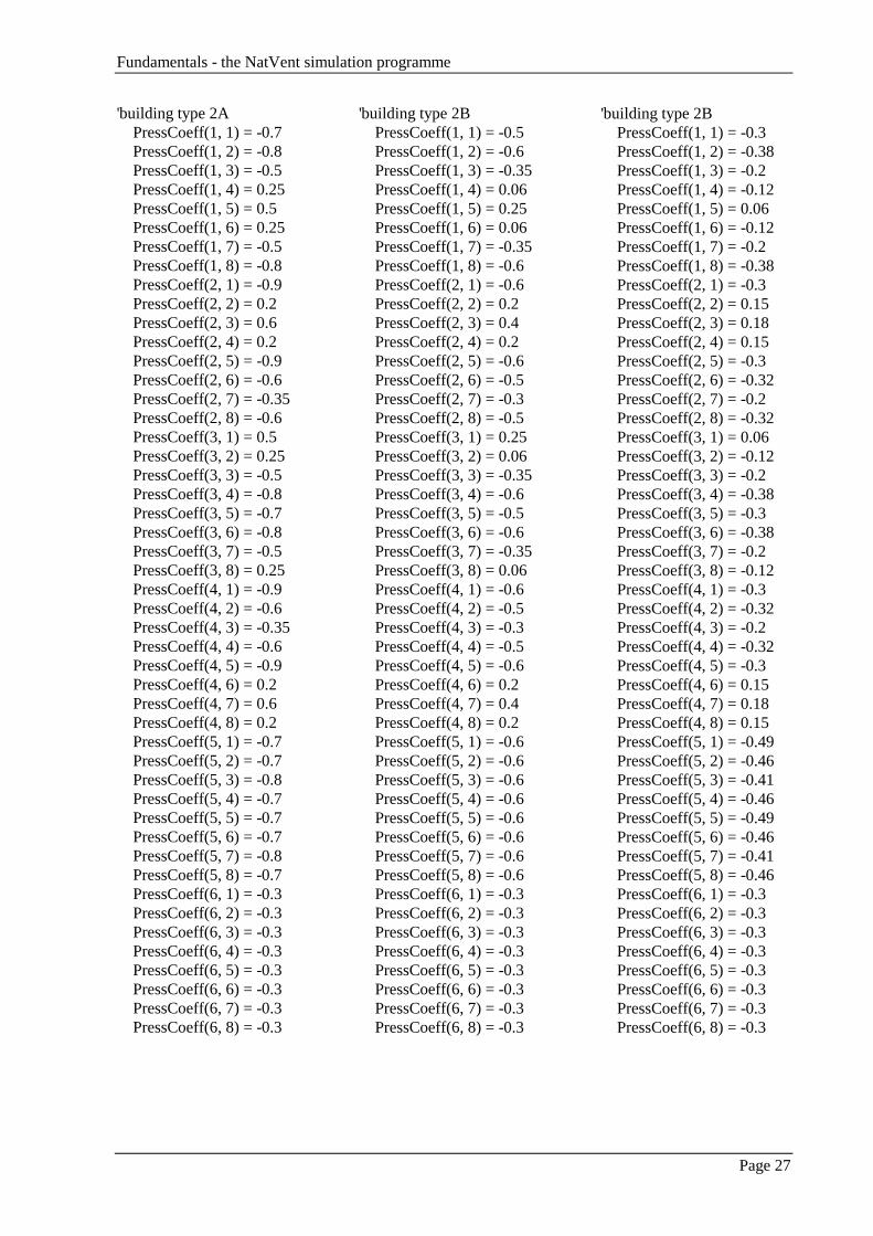
8 AppendixThe different types are according to Table 2.2 and the letters A to C stand for the different shieldingconditions. The pressure coefficients are presented as PressCoeff(facade, angle), where the values forfacade and the angle are described in the tables below (Liddament 1996).
Facade Surface1 Facade 12 Facade 23 Facade 34 Facade 45 Roof6 Stack devices
Angle Wind angle1 1802 2253 2704 3155 06 457 908 135

Fundamentals - the NatVent simulation programme
Page 26
'buildingtype 1A PressCoeff(1, 1) = -0.2 PressCoeff(1, 2) = -0.4 PressCoeff(1, 3) = -0.5 PressCoeff(1, 4) = 0.35 PressCoeff(1, 5) = 0.7 PressCoeff(1, 6) = 0.35 PressCoeff(1, 7) = -0.5 PressCoeff(1, 8) = -0.4 PressCoeff(2, 1) = -0.5 PressCoeff(2, 2) = 0.35 PressCoeff(2, 3) = 0.7 PressCoeff(2, 4) = 0.35 PressCoeff(2, 5) = -0.5 PressCoeff(2, 6) = -0.4 PressCoeff(2, 7) = -0.2 PressCoeff(2, 8) = -0.4 PressCoeff(3, 1) = 0.7 PressCoeff(3, 2) = 0.35 PressCoeff(3, 3) = -0.5 PressCoeff(3, 4) = -0.4 PressCoeff(3, 5) = -0.2 PressCoeff(3, 6) = -0.4 PressCoeff(3, 7) = -0.5 PressCoeff(3, 8) = 0.35 PressCoeff(4, 1) = -0.5 PressCoeff(4, 2) = -0.4 PressCoeff(4, 3) = -0.2 PressCoeff(4, 4) = -0.4 PressCoeff(4, 5) = -0.5 PressCoeff(4, 6) = 0.35 PressCoeff(4, 7) = 0.7 PressCoeff(4, 8) = 0.35 PressCoeff(5, 1) = -0.6 PressCoeff(5, 2) = -0.6 PressCoeff(5, 3) = -0.6 PressCoeff(5, 4) = -0.6 PressCoeff(5, 5) = -0.6 PressCoeff(5, 6) = -0.6 PressCoeff(5, 7) = -0.6 PressCoeff(5, 8) = -0.6 PressCoeff(6, 1) = -0.3 PressCoeff(6, 2) = -0.3 PressCoeff(6, 3) = -0.3 PressCoeff(6, 4) = -0.3 PressCoeff(6, 5) = -0.3 PressCoeff(6, 6) = -0.3 PressCoeff(6, 7) = -0.3 PressCoeff(6, 8) = -0.3
'buildingtype 1B PressCoeff(1, 1) = -0.2 PressCoeff(1, 2) = -0.35 PressCoeff(1, 3) = -0.3 PressCoeff(1, 4) = 0.1 PressCoeff(1, 5) = 0.4 PressCoeff(1, 6) = 0.1 PressCoeff(1, 7) = -0.3 PressCoeff(1, 8) = -0.35 PressCoeff(2, 1) = -0.3 PressCoeff(2, 2) = 0.1 PressCoeff(2, 3) = 0.4 PressCoeff(2, 4) = 0.1 PressCoeff(2, 5) = -0.3 PressCoeff(2, 6) = -0.35 PressCoeff(2, 7) = -0.2 PressCoeff(2, 8) = -0.35 PressCoeff(3, 1) = 0.4 PressCoeff(3, 2) = 0.1 PressCoeff(3, 3) = -0.3 PressCoeff(3, 4) = -0.35 PressCoeff(3, 5) = -0.2 PressCoeff(3, 6) = -0.35 PressCoeff(3, 7) = -0.3 PressCoeff(3, 8) = 0.1 PressCoeff(4, 1) = -0.3 PressCoeff(4, 2) = -0.35 PressCoeff(4, 3) = -0.2 PressCoeff(4, 4) = -0.35 PressCoeff(4, 5) = -0.3 PressCoeff(4, 6) = 0.1 PressCoeff(4, 7) = 0.4 PressCoeff(4, 8) = 0.1 PressCoeff(5, 1) = -0.6 PressCoeff(5, 2) = -0.5 PressCoeff(5, 3) = -0.4 PressCoeff(5, 4) = -0.5 PressCoeff(5, 5) = -0.6 PressCoeff(5, 6) = -0.5 PressCoeff(5, 7) = -0.4 PressCoeff(5, 8) = -0.5 PressCoeff(6, 1) = -0.3 PressCoeff(6, 2) = -0.3 PressCoeff(6, 3) = -0.3 PressCoeff(6, 4) = -0.3 PressCoeff(6, 5) = -0.3 PressCoeff(6, 6) = -0.3 PressCoeff(6, 7) = -0.3 PressCoeff(6, 8) = -0.3
'building type 1C PressCoeff(1, 1) = -0.25 PressCoeff(1, 2) = -0.3 PressCoeff(1, 3) = -0.25 PressCoeff(1, 4) = 0.05 PressCoeff(1, 5) = 0.2 PressCoeff(1, 6) = 0.05 PressCoeff(1, 7) = -0.25 PressCoeff(1, 8) = -0.3 PressCoeff(2, 1) = -0.25 PressCoeff(2, 2) = 0.05 PressCoeff(2, 3) = 0.2 PressCoeff(2, 4) = 0.05 PressCoeff(2, 5) = -0.25 PressCoeff(2, 6) = -0.3 PressCoeff(2, 7) = -0.25 PressCoeff(2, 8) = -0.3 PressCoeff(3, 1) = 0.2 PressCoeff(3, 2) = 0.05 PressCoeff(3, 3) = -0.25 PressCoeff(3, 4) = -0.3 PressCoeff(3, 5) = -0.25 PressCoeff(3, 6) = -0.3 PressCoeff(3, 7) = -0.25 PressCoeff(3, 8) = 0.05 PressCoeff(4, 1) = -0.25 PressCoeff(4, 2) = -0.3 PressCoeff(4, 3) = -0.25 PressCoeff(4, 4) = -0.3 PressCoeff(4, 5) = -0.25 PressCoeff(4, 6) = 0.05 PressCoeff(4, 7) = 0.2 PressCoeff(4, 8) = 0.05 PressCoeff(5, 1) = -0.5 PressCoeff(5, 2) = -0.5 PressCoeff(5, 3) = -0.4 PressCoeff(5, 4) = -0.5 PressCoeff(5, 5) = -0.5 PressCoeff(5, 6) = -0.5 PressCoeff(5, 7) = -0.4 PressCoeff(5, 8) = -0.5 PressCoeff(6, 1) = -0.3 PressCoeff(6, 2) = -0.3 PressCoeff(6, 3) = -0.3 PressCoeff(6, 4) = -0.3 PressCoeff(6, 5) = -0.3 PressCoeff(6, 6) = -0.3 PressCoeff(6, 7) = -0.3 PressCoeff(6, 8) = -0.3
Fundamentals - the NatVent simulation programme
Page 27
'building type 2A PressCoeff(1, 1) = -0.7 PressCoeff(1, 2) = -0.8 PressCoeff(1, 3) = -0.5 PressCoeff(1, 4) = 0.25 PressCoeff(1, 5) = 0.5 PressCoeff(1, 6) = 0.25 PressCoeff(1, 7) = -0.5 PressCoeff(1, 8) = -0.8 PressCoeff(2, 1) = -0.9 PressCoeff(2, 2) = 0.2 PressCoeff(2, 3) = 0.6 PressCoeff(2, 4) = 0.2 PressCoeff(2, 5) = -0.9 PressCoeff(2, 6) = -0.6 PressCoeff(2, 7) = -0.35 PressCoeff(2, 8) = -0.6 PressCoeff(3, 1) = 0.5 PressCoeff(3, 2) = 0.25 PressCoeff(3, 3) = -0.5 PressCoeff(3, 4) = -0.8 PressCoeff(3, 5) = -0.7 PressCoeff(3, 6) = -0.8 PressCoeff(3, 7) = -0.5 PressCoeff(3, 8) = 0.25 PressCoeff(4, 1) = -0.9 PressCoeff(4, 2) = -0.6 PressCoeff(4, 3) = -0.35 PressCoeff(4, 4) = -0.6 PressCoeff(4, 5) = -0.9 PressCoeff(4, 6) = 0.2 PressCoeff(4, 7) = 0.6 PressCoeff(4, 8) = 0.2 PressCoeff(5, 1) = -0.7 PressCoeff(5, 2) = -0.7 PressCoeff(5, 3) = -0.8 PressCoeff(5, 4) = -0.7 PressCoeff(5, 5) = -0.7 PressCoeff(5, 6) = -0.7 PressCoeff(5, 7) = -0.8 PressCoeff(5, 8) = -0.7 PressCoeff(6, 1) = -0.3 PressCoeff(6, 2) = -0.3 PressCoeff(6, 3) = -0.3 PressCoeff(6, 4) = -0.3 PressCoeff(6, 5) = -0.3 PressCoeff(6, 6) = -0.3 PressCoeff(6, 7) = -0.3 PressCoeff(6, 8) = -0.3
'building type 2B PressCoeff(1, 1) = -0.5 PressCoeff(1, 2) = -0.6 PressCoeff(1, 3) = -0.35 PressCoeff(1, 4) = 0.06 PressCoeff(1, 5) = 0.25 PressCoeff(1, 6) = 0.06 PressCoeff(1, 7) = -0.35 PressCoeff(1, 8) = -0.6 PressCoeff(2, 1) = -0.6 PressCoeff(2, 2) = 0.2 PressCoeff(2, 3) = 0.4 PressCoeff(2, 4) = 0.2 PressCoeff(2, 5) = -0.6 PressCoeff(2, 6) = -0.5 PressCoeff(2, 7) = -0.3 PressCoeff(2, 8) = -0.5 PressCoeff(3, 1) = 0.25 PressCoeff(3, 2) = 0.06 PressCoeff(3, 3) = -0.35 PressCoeff(3, 4) = -0.6 PressCoeff(3, 5) = -0.5 PressCoeff(3, 6) = -0.6 PressCoeff(3, 7) = -0.35 PressCoeff(3, 8) = 0.06 PressCoeff(4, 1) = -0.6 PressCoeff(4, 2) = -0.5 PressCoeff(4, 3) = -0.3 PressCoeff(4, 4) = -0.5 PressCoeff(4, 5) = -0.6 PressCoeff(4, 6) = 0.2 PressCoeff(4, 7) = 0.4 PressCoeff(4, 8) = 0.2 PressCoeff(5, 1) = -0.6 PressCoeff(5, 2) = -0.6 PressCoeff(5, 3) = -0.6 PressCoeff(5, 4) = -0.6 PressCoeff(5, 5) = -0.6 PressCoeff(5, 6) = -0.6 PressCoeff(5, 7) = -0.6 PressCoeff(5, 8) = -0.6 PressCoeff(6, 1) = -0.3 PressCoeff(6, 2) = -0.3 PressCoeff(6, 3) = -0.3 PressCoeff(6, 4) = -0.3 PressCoeff(6, 5) = -0.3 PressCoeff(6, 6) = -0.3 PressCoeff(6, 7) = -0.3 PressCoeff(6, 8) = -0.3
'building type 2B PressCoeff(1, 1) = -0.3 PressCoeff(1, 2) = -0.38 PressCoeff(1, 3) = -0.2 PressCoeff(1, 4) = -0.12 PressCoeff(1, 5) = 0.06 PressCoeff(1, 6) = -0.12 PressCoeff(1, 7) = -0.2 PressCoeff(1, 8) = -0.38 PressCoeff(2, 1) = -0.3 PressCoeff(2, 2) = 0.15 PressCoeff(2, 3) = 0.18 PressCoeff(2, 4) = 0.15 PressCoeff(2, 5) = -0.3 PressCoeff(2, 6) = -0.32 PressCoeff(2, 7) = -0.2 PressCoeff(2, 8) = -0.32 PressCoeff(3, 1) = 0.06 PressCoeff(3, 2) = -0.12 PressCoeff(3, 3) = -0.2 PressCoeff(3, 4) = -0.38 PressCoeff(3, 5) = -0.3 PressCoeff(3, 6) = -0.38 PressCoeff(3, 7) = -0.2 PressCoeff(3, 8) = -0.12 PressCoeff(4, 1) = -0.3 PressCoeff(4, 2) = -0.32 PressCoeff(4, 3) = -0.2 PressCoeff(4, 4) = -0.32 PressCoeff(4, 5) = -0.3 PressCoeff(4, 6) = 0.15 PressCoeff(4, 7) = 0.18 PressCoeff(4, 8) = 0.15 PressCoeff(5, 1) = -0.49 PressCoeff(5, 2) = -0.46 PressCoeff(5, 3) = -0.41 PressCoeff(5, 4) = -0.46 PressCoeff(5, 5) = -0.49 PressCoeff(5, 6) = -0.46 PressCoeff(5, 7) = -0.41 PressCoeff(5, 8) = -0.46 PressCoeff(6, 1) = -0.3 PressCoeff(6, 2) = -0.3 PressCoeff(6, 3) = -0.3 PressCoeff(6, 4) = -0.3 PressCoeff(6, 5) = -0.3 PressCoeff(6, 6) = -0.3 PressCoeff(6, 7) = -0.3 PressCoeff(6, 8) = -0.3

Fundamentals - the NatVent simulation programme
Page 28
'building type 3A PressCoeff(1, 1) = -0.34 PressCoeff(1, 2) = -0.47 PressCoeff(1, 3) = -0.46 PressCoeff(1, 4) = 0.24 PressCoeff(1, 5) = 0.49 PressCoeff(1, 6) = 0.24 PressCoeff(1, 7) = -0.46 PressCoeff(1, 8) = -0.47 PressCoeff(2, 1) = -0.61 PressCoeff(2, 2) = 0.14 PressCoeff(2, 3) = 0.4 PressCoeff(2, 4) = 0.14 PressCoeff(2, 5) = -0.61 PressCoeff(2, 6) = -0.39 PressCoeff(2, 7) = -0.19 PressCoeff(2, 8) = -0.39 PressCoeff(3, 1) = 0.49 PressCoeff(3, 2) = 0.24 PressCoeff(3, 3) = -0.46 PressCoeff(3, 4) = -0.47 PressCoeff(3, 5) = -0.34 PressCoeff(3, 6) = -0.47 PressCoeff(3, 7) = -0.46 PressCoeff(3, 8) = 0.24 PressCoeff(4, 1) = -0.61 PressCoeff(4, 2) = -0.39 PressCoeff(4, 3) = -0.19 PressCoeff(4, 4) = -0.39 PressCoeff(4, 5) = -0.61 PressCoeff(4, 6) = 0.14 PressCoeff(4, 7) = 0.4 PressCoeff(4, 8) = 0.14 PressCoeff(5, 1) = -0.6 PressCoeff(5, 2) = -0.53 PressCoeff(5, 3) = -0.58 PressCoeff(5, 4) = -0.53 PressCoeff(5, 5) = -0.6 PressCoeff(5, 6) = -0.53 PressCoeff(5, 7) = -0.58 PressCoeff(5, 8) = -0.53 PressCoeff(6, 1) = -0.3 PressCoeff(6, 2) = -0.3 PressCoeff(6, 3) = -0.3 PressCoeff(6, 4) = -0.3 PressCoeff(6, 5) = -0.3 PressCoeff(6, 6) = -0.3 PressCoeff(6, 7) = -0.3 PressCoeff(6, 8) = -0.3
Related Documents


