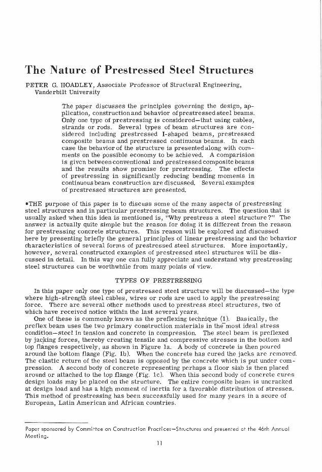
The Nature of Prestressed Steel Structures PETER G. HOADLEY, Associate Professor of Structural Engineering, Vanderbilt University The paper discusses the principles governing the design, ap- plication, construction and bE:havior ofprestressed steel beams. Only one type of prestressing is considered-that using cables, strands or rods. Several types of beam structures are con- sidered including prestressed I-shaped beams, prestressed composite beams and prestressed continuous beams. In each case the behavior of the structure is presentedalong with com- ments on the possible economy to be achieved. A comparision is given between conventional and prestressed composite beams and the results show promise for prestressing. The effects of prestressing in significantly reducing bending moments in continuous beam construction are discussed. Several examples of prestressed structures are presented. •THE purpose of this paper is to discuss some of the many aspects of prestressing steel structures and in particular prestressing beam structures. The question that is usually asked when this idea is mentioned is, "Why pre stress a steel structure?" The answer is actually quite simple but the reason for doing it is different from the reason for prestressing concrete structures. This reason will be explored and discussed here by presenting briefly the general principles of linear prestressing and the behavior characteristics of several forms of pre stressed steel structures. More importantly, however, several constructed examples of prestressed steel structures will be dis- cussed in detail. In this way one can fully appreciate and understand why prestressing steel structures can be worthwhile from many points of view. TYPES OF PRESTRESSING In this paper only one type of prestressed steel structure will be discussed-the type where high-strength steel cables, wires or rods are used to apply the prestressing force. There are several other methods used to prestress steel structures, two of which have received notice within the last several years. One of these is commonly known as the preflexing technique (1). Basically, the preflex beam uses the two primary construction materials in the- most ideal stress condition-steel in tension and concrete in compression. The steel beam is preflexed by jac,king forces, thereby creating tensile and compressive stresses in the bottom and top flanges respectively, as shown in Figure la. A body of concrete is then poured around the bottom flange (Fig. lb). When the concrete has cured the jacks are removed. The elastic return of the steel beam is opposed by the concrete which is put under com- pression. A second body of concrete representing perhaps a floor slab is then placed around or attached to the top flange (Fig. le). When this second body of concrete cures design loads may be placed on the structure. The entire composite beam is uncracked at design load and has a high moment of inertia for a favorable distribution of stresses. This method of prestressing has been successfully used for many years in a score of European, Latin American and African countries . Paper sponsored by Committee on Construction Practices-Structures and present ed at the 46th Annual Meeting. 11

Welcome message from author
This document is posted to help you gain knowledge. Please leave a comment to let me know what you think about it! Share it to your friends and learn new things together.
Transcript
The Nature of Prestressed Steel Structures PETER G. HOADLEY, Associate Professor of Structural Engineering,
Vanderbilt University
The paper discusses the principles governing the design, application, construction and bE:havior ofprestressed steel beams. Only one type of prestressing is considered-that using cables, strands or rods. Several types of beam structures are considered including prestressed I-shaped beams, prestressed composite beams and prestressed continuous beams. In each case the behavior of the structure is presentedalong with comments on the possible economy to be achieved. A comparision is given between conventional and prestressed composite beams and the results show promise for prestressing. The effects of prestressing in significantly reducing bending moments in continuous beam construction are discussed. Several examples of prestressed structures are presented.
•THE purpose of this paper is to discuss some of the many aspects of prestressing steel structures and in particular prestressing beam structures. The question that is usually asked when this idea is mentioned is, "Why pre stress a steel structure?" The answer is actually quite simple but the reason for doing it is different from the reason for prestressing concrete structures. This reason will be explored and discussed here by presenting briefly the general principles of linear prestressing and the behavior characteristics of several forms of pre stressed steel structures. More importantly, however, several constructed examples of prestressed steel structures will be discussed in detail. In this way one can fully appreciate and understand why prestressing steel structures can be worthwhile from many points of view.
TYPES OF PRESTRESSING
In this paper only one type of prestressed steel structure will be discussed-the type where high-strength steel cables, wires or rods are used to apply the prestressing force. There are several other methods used to prestress steel structures, two of which have received notice within the last several years.
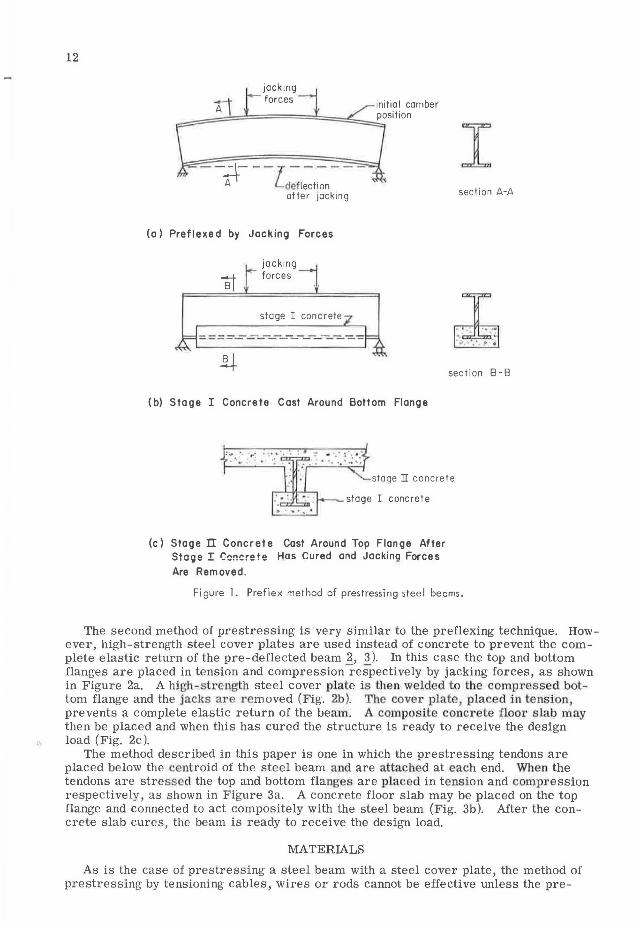
One of these is commonly known as the preflexing technique (1). Basically, the preflex beam uses the two primary construction materials in the-most ideal stress condition-steel in tension and concrete in compression. The steel beam is preflexed by jac,king forces, thereby creating tensile and compressive stresses in the bottom and top flanges respectively, as shown in Figure la. A body of concrete is then poured around the bottom flange (Fig. lb). When the concrete has cured the jacks are removed. The elastic return of the steel beam is opposed by the concrete which is put under compression. A second body of concrete representing perhaps a floor slab is then placed around or attached to the top flange (Fig. le). When this second body of concrete cures design loads may be placed on the structure. The entire composite beam is uncracked at design load and has a high moment of inertia for a favorable distribution of stresses. This method of prestressing has been successfully used for many years in a score of European, Latin American and African countries .
Paper sponsored by Committee on Construction Practices-Structures and presented at the 46th Annual Meeting.
11
12
Ti jacking farces
-- i+ --[deflection - - -
after jacking
(a) Prefle>led by Jacking Forces
jacking forces
stage I concrete
(bl Stage I Concrete Cast Around Bottom Flange
I section A-A
section B-B
·'• .. •. ·: ~- :_:. : . ...•. ;; stage II concrete t- ·· ·r·~ :: stoge I co•mte
... . "", .
(c) Stage n Concrete Cast Around Top Flange After Stage I Concrete Has Cured and Jocking Forces Are Removed.
Figure l. Pref lex method of prestressing steel beams.
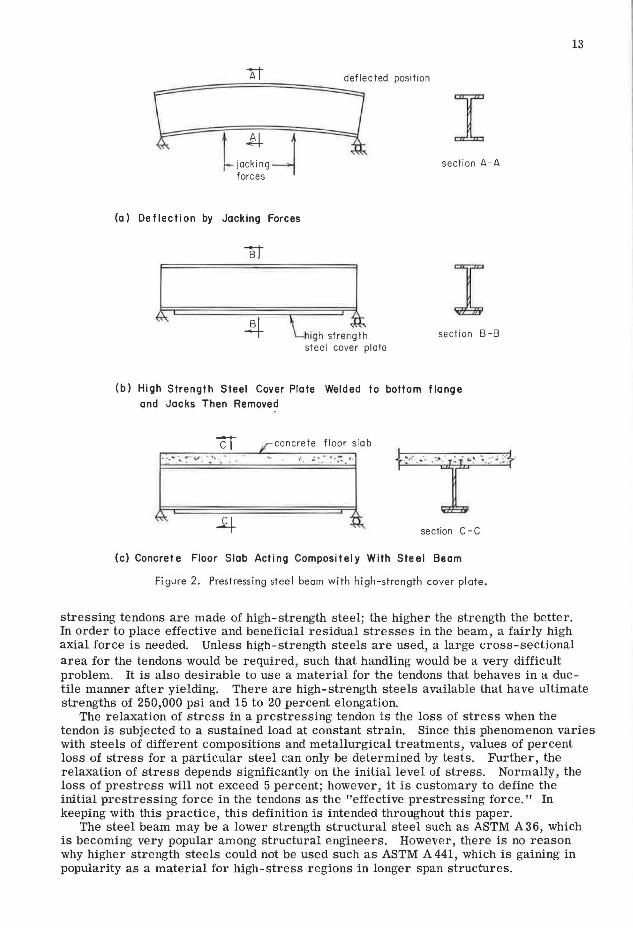
The second method of prestressing is very similar to the preflexing technique. However, high-strength steel cover plates are used instead of concrete to prevent the complete elastic return of the pre-deflected beam 2, 3). In this case the top and bottom flanges are placed in tension and compression respectively by jacking forces, as shown in Figure 2a. A high -strength steel cover plate is then welded to the compressed bottom flange and the jacks a r 1·emoved (Fig. 2b). The cover plate, placed in tension, prevents a complete elastic return of the beam. A composite concrete floor slab may then be placed and when this has cured the structure is ready to receive the design load (Fig. 2c ).
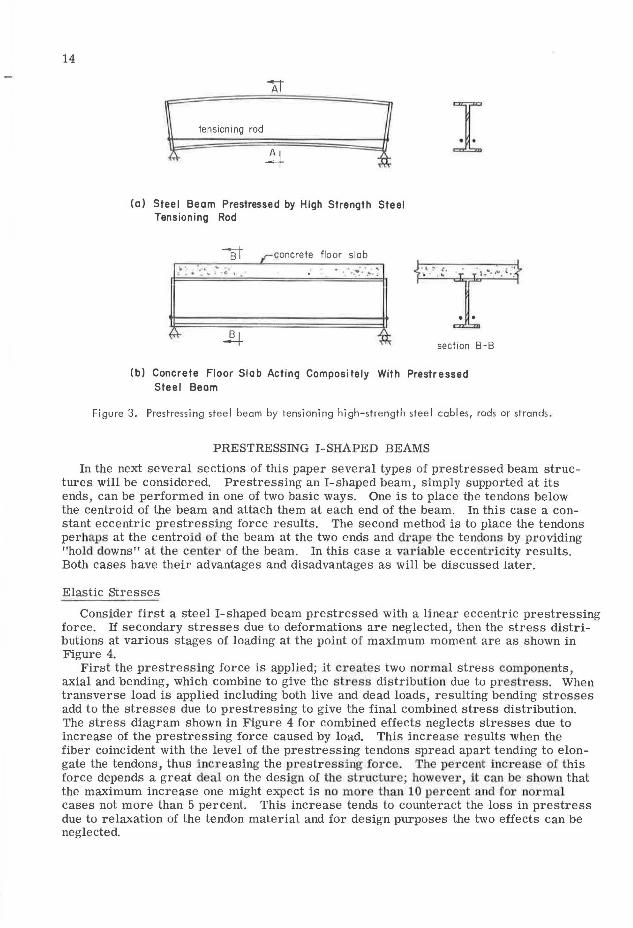
The method described in this paper is one in which the prestressing tendons are placed below the centroid of the steel beam and are attached at each end. When the tendons are stressed the top and bottom flanges are placed in tension and compression respectively, as shown in Figure 3a. A concrete floor slab may be placed on the top flange and connected to act compositely with the steel beam (Fig. 3b). After the concrete slab cures, the beam is ready to receive the design load.
MATERIALS
As is the case of prestressing a steel beam with a steel cover plate, the method of prestressing by tensioning cables, wires or rods cannot be effective unless the pre-
-=============~de~f_:lected position
I L!,~
forces section A-A
(a) Deflection by Jacking Forces
l. 1 I 4 \...high strength section B-B
steel cover plate
(b) High Strength Steel Cover Plate Welded to bottom flange and Jacks Then Removed
n /"" conc rete fl oor slab ··: ... .. -~·"". · ... ·· _~.'. :.·: ~- :: .•-
section C-C
(c) Concrete Floor Slab Acting Compositely With Steel Beam
Figure 2 . Prestressing steel beam with high-strength cove r plate.
stressing tendons are made of high-strength steel; the higher the strength the better.
13
In order to place effective and beneficial residual stresses in the beam, a fairly high axial force is needed. Unless high-strength steels are used, a large cross-sectional area for the tendons would be required, such that handling would be a very difficult problem. It is also desirable to use a material for the tendons that behaves in a ductile manner after yielding. There are high-strength steels available that have ultimate strengths of 250,000 psi and 15 to 20 percent elongation.
The relaxation of stress in a prestressing tendon is the loss of stress when the tendon is subjected to a sustained load at constant strain. Since this phenomenon varies with steels of different compositions and metallurgical treatments, values of percent loss of stress for a particular steel can only be determined by tests. Further, the relaxation of stress depends significantly on the initial level of stress. Normally, the loss of prestress will not exceed 5 percent; however , it is customary to define the initial prestressing force in the tendons as the "effective prestressing force." In keeping with this practice, this definition is intended throughout this paper.
The steel beam may be a lower strength structural steel such as ASTM A36, which is becoming very popular among structural engineers. However , there is no reason why higher strength steels could not be used such as ASTM A 441 , which is gaining in popularity as a material for high-stress regions in longer span structures.
14
At
lens ion i ng rod
4 ~ ~. (a) Steel Beam Prestressed by High Strength Steel
Tensioning Rod
sf ,,-concrete floor slob ~ •. ·· • ~ .
L • • _ .., • 0 1 . . ·.:•:. · ....
I
. . . .. , ... · •"". '"·.
section B-B
(bl Concrete Floor Slab Acting Compositely With Prestressed Steel Beam
Figure 3. Prestress i ng stee I beam by tensioning high-strength stee I cab I es, rods or strands .
PRESTRESSING I-SHAPED BEAMS
In the next several sections of this paper several types of prestressed beam structures will be considered. Prestressing an I-shaped beam, simply supported at its ends, can be performed in one of two basic ways. One is to place the tendons below the centroid of the beam and attach them at each end of the beam. In this case a constant eccentric prestressing force results. The second method is to place the tendons perhaps at the centroid of the beam at the two ends and drape the tendons by providing "hold downs" at the ce11ter of the beam. In this case a variable eccentricity results. Both cases have their advantages and disadvantages as will be discussed later.
Elastic Stresses
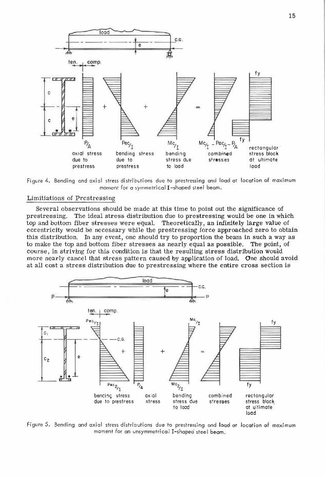
Consider first a steel I-shaped beam prestressed with a linear eccentric prestressing force. If secondary stresses due to deformations are neglected, then the stress distributions at various stages of loading at the point of maximum moment are as shown in Figure 4.
First the prestressing force is applied; it creates two normal stress components, axial and bending, which combine to give the stress distribution due to presb-ess. When transverse load is applied including both live and dead loads, resulting bending stresses add to the stresses due to prestressing to give the final combined stress distribution. The stress diagram shown in Figure 4 for combined effects neglects stresses due to increase of the prestressing force caused by load. This increase results when the fiber coincident with the level of the prestressing tendons spread apart tending to elongate the tendons, thus increasing the pre stressing force. The percent increase of lhis force depends a great deal on the design of the structure; however, it can be sbown that the maximum increase one might expect is no more than 10 percent and for normal cases not more than 5 percent. This increase tends to counteract the loss in prestress due to relaxation of the tendon material and for design purposes the two effects can be neglected.
15
len . , j c~mp.
fy
+
P;A Pec11 Mc/I Mc1 _ Pec1 - lz fy
I I A rectangular axial stress bending stress bending combined stress block due to due to stress due stress es at ultimote pre stress pre stress to load load
Figure 4. Bending and axial stress distributions due to prestressing and load at location of maximum moment for a symmetrical I-shaped steel beam.
Limitiations of Prestressing
Several observations should be made at this time to point out the significance of prestressing. The ideal stress distribution due to prestressing would be one in which top and bottom fiber stresses were equal. Theoretically, an infinitely large value of eccentricity would be necessary while the prestressing force approached zero to obtain this distribution. In any event, one should try to proportion the beam in such a way as to make the top and bottom fiber stresses as nearly equal as possible. The point, of course, in striving for this condition is that the resulting stress distribution would more nearly cancel that stress pattern caused by application of load. One should avoid at all cost a stress distribution due to prestressing where the entire cross section is
I~. I c1omp.
Pec,11
+
Pec 2 P1A /1
bending stress axial due to prestress stress
Mc2 tr
bending stress due to load
combined stresses
fy
fy
rectangular stress block at ultimate · load
Figure 5. Bending and axial stress distributions due to prestressing and load at location of maximum moment for on unsymmetrical I-shaped steel beam.
16
LOAD
~WARD DEFLECTION DUE TO PRESTRESS
DEFLECTION
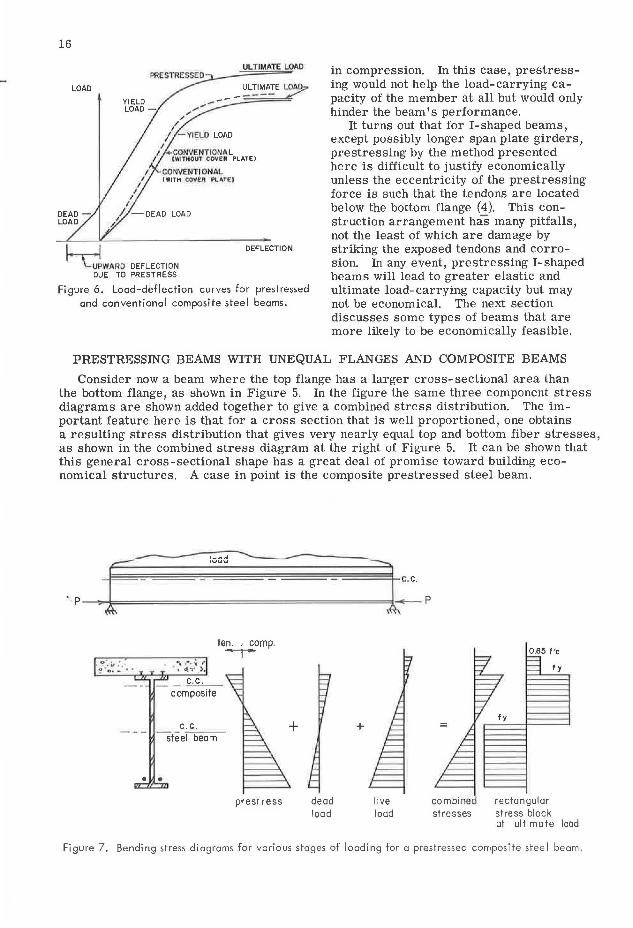
Figure 6. Load-deflection curves for prestressed and conventional composite steel beams.
in compression. In this case, prestressing would not help the load-carrying capacity of the member at all but would only hinder the beam's performance.
It turns out that for I-shaped beams, except possibly longer span plate girders, prestressing by the method presented here is difficult to justify economically unless the eccentricity of the prestressing force is such that the tendons are located below the bottom flange (4). This construction arrangement has many pitfalls, not the least of which are damage by striking the exposed tendons and corrosion. In any event, prestressing I-shaped beams will lead to greater elastic and ultimate load-carrying capacity but may not be economical. The next section discusses some types of beams that are more likely to be economically feasible.
PRESTRESSING BEAMS WITH UNEQUAL FLANGES AND COMPOSITE BEAMS
Consider now a beam where the top flange has a larger cross-sectional area than the bottom flange, as shown in Figure 5. In the figure the same three component stress diagrams are shown added together to give a combined stress distribution. The important feature here is that for a cross section that is well proportioned, one obtains a resulting stress distribution that gives very nearly equal top and bottom fiber stresses, as shown in the combined stress diagram at the right of Figure 5. It can be shown that this general cross-sectional shape has a great deal of promise toward building economical structures. A case in point is the composite prestressed steel beam.
# ,uuu --
"P- ~-¼==~==-==================~1'·' p
---- , __ ,. .......________ ___ _
composite
c.c. s teel beam
• • pres! ress
+
dead load
+
live load
0.85 f'c
fy
combined rectangular stresses stress block
at ultimate load
Figure 7. Bending stress diagrams for various stages of loading for a prestressed composite steel beam.
17
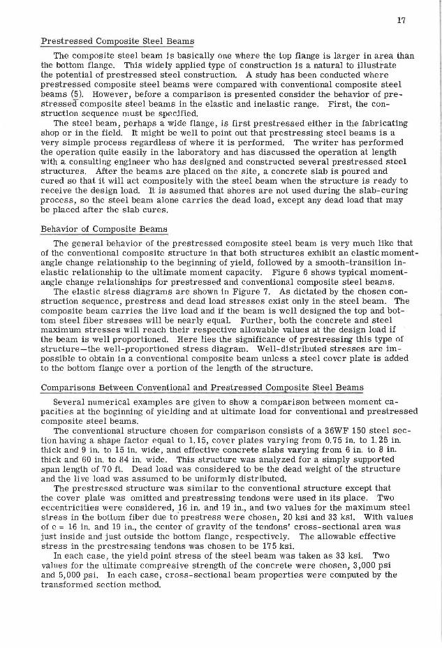
Prestressed Composite Steel Beams
The composite steel beam is basically one where the top flange is larger in area than the bottom flange. This widely applied type of construction is a natural to illustrate the potential of prestressed steel construction. A study has been conducted where prestressed composite steel beams were compared with conventional composite steel beams (5 ). However, before a comparison is presented consider the behavior of prestressed composite steel beams in the elastic and inelastic range. First, the construction sequence must be specified.
The steel beam, perhaps a wide flange, is first prestressed either in the fabricating shop or in the field. It might be well to point out that prestressing steel beams is a very simple process regardless of where it is performed. The writer has performed the operation quite easily in the laboratory and has discussed the operation at length with a consulting engineer who has designed and constructed several prestressed steel structures. After the beams are placed on the site, a concrete slab is poured and cured so that it will act compositely with the steel beam when the structure is ready to receive the design load. It is assumed that shores are not used during the slab-curing process, so the steel beam alone carries the dead load, except any dead load that may be placed after the slab cures.
Behavior of Composite Beams
The general behavior of the prestressed composite steel beam is very much like that of the conventional composite structure in that both structures exhibit an elastic momentangle change relationship to the beginning of yield, followed by a smooth-transition inelastic relationship to the ultimate moment capacity. Figure 6 shows typical momentangle change relationships for prestressed and conventional composite steel beams.
The elastic stress diagrams are shown in Figure 7. As dictated by the chosen construction sequence, prestress and dead load stresses exist only in the steel beam. The composite beam carries the live load and if the beam is well designed the top and bottom steel fiber stresses will be nearly equal. Further, both the concrete and steel maximum stresses will reach their respective allowable values at the design load if the beam is well proportioned. Here lies the significance of prestressing this type of structure-the well-proportioned stress diagram. Well-distributed stresses are impossible to obtain in a conventional composite beam unless a steel cover plate is added to the bottom flange over a portion of the length of the structure.
Comparisons Between Conventional and Prestressed Composite Steel Beams
Several numerical examples are given to show a comparison between moment capacities at the beginning of yielding and at ultimate load for conventional and prestressed composite steel beams.
The conventional structure chosen for comparison consists of a 36WF 150 steel section having a shape factor equal to 1.15, cover plates varying from 0. 75 in. to 1. 25 in. thick and 9 in. to 15 in. wide, and effective concrete slabs varying from 6 in. to 8 in. thick and 60 in. to 84 in. wide. This structure was analyzed for a simply supported span length of 70 ft. Dead load was considered to be the dead weight of the structure and the live load was assumed to be uniformly distributed.
The prestressed structure was similar to the conventional structure except that the cover plate was omitted and prestressing tendons were used in its place. Two eccentricities were considered, 16 in. and 19 in., and two values for the maximum steel stress in the bottom fiber due to' prestress were chosen, 20 ksi and 33 ksi. With values of e = 16 in. and 19 in., the center of gravity of the tendons' cross-sectional area was just inside and just outside the bottom flange , respectively. The allowable effective stress in the prestressing tendons was chosen to be 17 5 ksi.
In each case, the yield point stress of the steel beam was taken as 33 ksi. Two values for the ultimate compresive strength of the concrete were chosen, 3,000 psi and 5,000 psi. In each case, cross-sectional beam properties were computed by the transformed section method.
18
TABLE 1 EFFECT OF VARIATION IN SLAB DIMENSION ON MOMENT
RATIOS-RELATIVELY EFFICIENT USE OF PRESTRESSING
slab slab My Mp M'y /My
M'p /Mp t'c width depth
psi in. in. in. -kips in.-ki ps
3000 60 6 33,550 43,400 1.38 8 34,670 44,710 1.34
84 6 33,960 43,750 1. 36 8 34,960 48,400 1.40
5000 60 6 34,650 45,700 1.37 8 35,870 49,000 1.38
84 6 34,860 47,300 1.33 8 35,860 51,000 1.42
L = 70'-o" Ap = 12.0 in.2 36 VF 150 e = 19" <T'bp = 33 ksi Ap;As = 3.85 P = 546K As = 3.12 in.2
TABLE 2
EFFECT OF VARIATION IN SLAB DIMENSION ON MOMENT RATIOS-RELATIVELY INEFFICIENT USE
OF PRESTRESSING
1.21 1.26 1.26 1.22 1.22 1.23 1.22 1.23
slab slab My Mp My/ M'p/ Fe width depth My Mp psi in. l n. in.-kios in.- kios
3000 60 6 33,550 43,400 1.05 1.00 8 34,670 44,710 1.03 1.03
84 6 33,960 43,750 1.06 1.03
8 34,960 48,400 1.06 1.00 5000 60 6 34,650 45,700 1.05 1.01
8 35,870 49,000 1.06 1.01 84 6 34,860 47,300 1.03 1.01
8 35,860 51,000 1.08 1.01
L'.'.'. 701 -011 ~ n - !2 .0in.2 36\AF !50 ~~
e = 16" c:r bp = 20 ksi A%s= 5.72 P = 366 As = 2.09 in.2
TABLE 3
EFFECT OF VARIATION IN COVER PLATE DIMENSIONS ON MOMENT RATIOS-RELATIVELY EFFICIENT USE OF PRESTRESSING
cover cover Ap My Mp Ap M'y/ M'p/ plate plate As My Mp thickness width in.2 in.- kips in.- kips in. in.
0.75 9 6,75 28,030 39,440 2.17 1.67 1.41
15 11.25 33,550 44,780 3,61 1,39 1.24
1.25 9 11,25 33,150 44,980 3.61 1. 41 1.24 15 18.75 42,020 53,640 6.02 I. II 1,04
L =70'-o" 36 W'" 150 b = 72" As= 3.12 in,2 t'c = 3, OOOpsi d = 7" p = 546K e = 19.0" <f'bp = 3 3 ksi
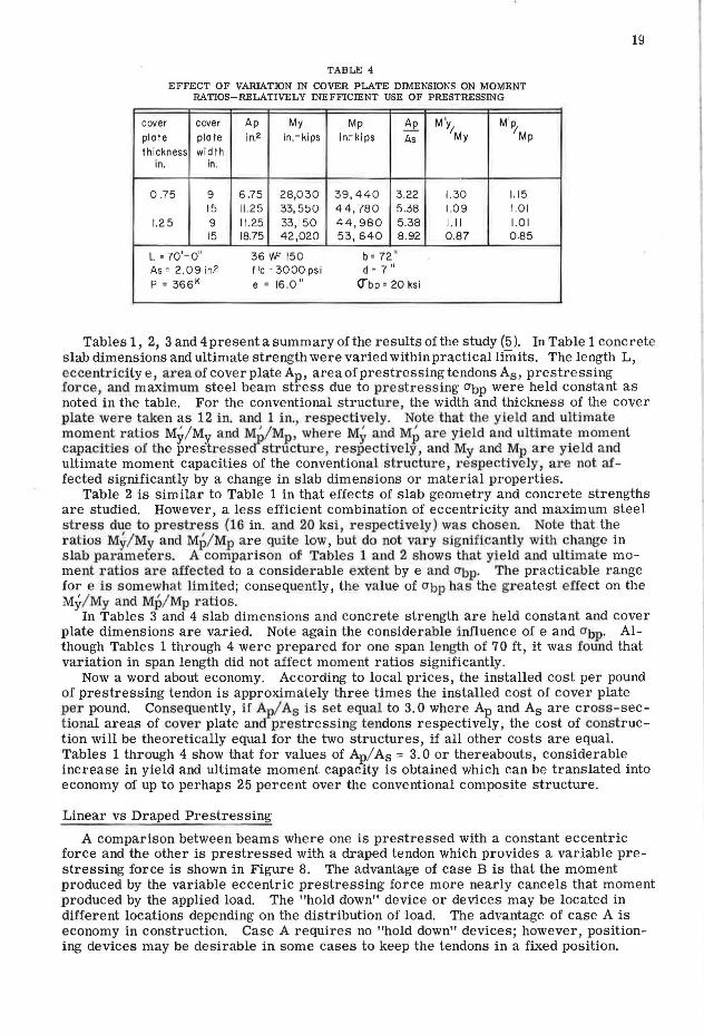
TABLE 4
EFFECT OF VARIATION IN COVER PLATE DThiENSIONS ON MOMENT RATIOS-RELATIVELY INEFFICIENT USE OF PRESTRESSING
cover cover Ap My Mp Ap M\ M''} plate plate in.2 in.-kips in.-kips As My Mp
th ickness wi dth in. in.
0 .75 9 6.75 28,0 30 39 , 44 0 3 .22 1.30 1. 15 15 1125 33,550 44,780 5 .38 1.09 1.01
1.25 9 11 .25 33, 150 44,980 5.38 I. II 1.01 15 18.75 42,020 53,640 8 .92 0.87 0,85
L = 70'-o" 36 VF 150 b = 72 " As= 2.09 in.2 f 'c = 3000 psi d = 7" P = 366K e = 16.0" 0-bp = 20 ksi
19
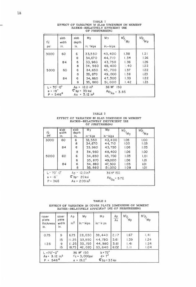
Tables 1, 2, 3 and 4 present a summary of the results of the study (5 ). In Table 1 concrete slab dimensions and ultimate strength were varied within practical limits. The length L, eccentricity e, area of cover plate Ap, areaofprestressing tendons As, prestressing force, and maximum steel beam stress due to pr estressing abp were held constant as noted in the table. For the conventional structure, the width and thickness of the cover plate wer e taken as 12 in. and 1 in., respecti vely. Note t hat the yield and ultimate moment ratios My/ My and M{/Mp, where My and Mp ar e yield a nd ultimate moment capacities of the prestressed s tructure, r espectively, and My and Mp are yield a nd ultimate moment capacities of the conventional structure , r espectively, are not affected significantly by a change in slab dimensions or material properties.
Table 2 is similar to Table 1 in that effects of slab geometry and concrete strengths are studied. However, a less efficient combination of eccentricity and maximum steel st r ess due to prestress (16 in. and 20 ksi , respect ively) was chosen. Note that the r atios My/My and Mp/ Mp are quite low, but do not vary significantly with change in slab par ameters. A comparison of Tables 1 and 2 shows that yield and ultimat e moment r atios are affected to a considerable extent by e and O"bp• The practicable range for e i.s s omewhat limited; consequently, the value of a bp has the gr eatest effect on the My/ My and Mp/ Mp ratios.
In Tables 3 and 4 slab dimensions and concrete strength are held constant and cover plate dimensions are varied. Note again the considerable influence of e and O"bp· Although Tables 1 through 4 were prepared for one span length of 70 ft, it was found that variation in span length did not affect moment ratios significantly.
Now a word about economy. According to local prices, the installed cost per pound of prestressing tendon is approximately three times the installed cost of cover plate per pound. Consequently, if Ap/ As is set equal to 3.0 where Ap and As are cros s - sectional areas of cover plate and prestressing tendons respectively, the cost of construction will be theoretically equal for the two structures, if all other costs are equal. Tables 1 through 4 show that for values of Ap/ As = 3. 0 or thereabouts, considerable increase in yield and ultimate moment capacity is obtained which can be translated into economy of up to perhaps 25 percent over the conventional composite structure.
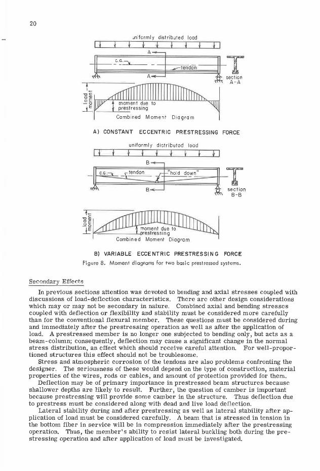
Linear vs Draped Prestressing
A comparison between beams where one is prestressed with a constant eccentric force and the other is prestressed with a draped tendon which provides a variable prestressing force is shown in Figure 8. The advantage of case B is that the moment produced by the variable eccentric prestressing force more nearly cancels that moment produced by the applied load. The "hold down" device or devices may be located in different locations depending on the distribution of load. The advantage of case A is economy in construction. Case A requires no "hold down" devices; however, positioning devices may be desirable in some cases to keep the tendons in a fixed position.
20
uniformly distributed load
I I
Comb ined Moment Diagram
A) CONSTANT ECCENTRIC PRESTRESSING FORCE
uniform I y distributed load
I I I } ~ t I I B
C.C! . tendon ''hold down '' T B section
B-B
B) VARIABLE ECCENTRIC PRESTRESSI NG FORCE
Figure 8. Moment diagrams for two basic prestressed systems.
In previous sections attention was devoted to bending and axial stresses coupled with discussions of load-deflection characteristics. There are other design considerations which may or may not be secondary in nature. Combined axial and bending stresses coupled with deflection or flexibility and stability must be considered more carefully than for the conventional flexural member. These questions must be considered during and immediately after the prestressing operation as well as after the application of load. A pre stressed member is no longer one subjected to bending only, but acts as a beam-column; consequently, deflection may cause a significant change in the normal stress distribution, an effect whi~h should receive careful attention For well-proportioned structures this effect should not be troublesome.
Stress and atmospheric corrosion of the tendons are also problems confronting the designer. The seriousness of these would depend on the type of construction, material properties of the wires, rods or cables, and amount of protection provided for them.
Deflection may be of primary importance in prestressed beam structures because shallower depths are likely to result. Further, the question of camber is important because prestressing will provide some camber in the structure. Thus deflection due to prestress must be considered along with dead and live load deflection.
Lateral stability during and after prestressing as well as lateral stability after application of load must be considered carefully. A beam that is stressed in tension in the bottom fiber in service will be in compression immediately after the prestressing operation. Thus, the member's ability to resist lateral buckling both during the prestressing operation and after application of load must be investigated.
I I I I I I
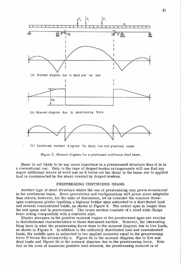
(a) Moment diagram due to dead and live load
I I
w I II I I I I
l~-----'~I (b) Moment diagram due to prestressing force
(c) Combined moment diagram for dead, live and prestress loads
Figure 9. Moment diagrams for a prestressed continuous steel beam.
21
Shear is not likely to be any more important in a prestressed structure than it is in a conventional one. Only in the case of draped tendon arrangements will one find any major additional forces at work and as it turns out the shear in the beam due to applied load is counteracted by the shear created by draped tendons.
PRESTRESSING CONTINUOUS BEAMS
Another type of steel structure where the use of prestressing may prove economical is the continuous beam. Some geometries and configurations will prove more adaptable than others; however, for the sake of discussion, let us consider the common threespan continuous girder typifying a highway bridge span subjected to a distributed load and several concentrated loads, as shown in Figure 9. The center span is longer than the end spans and is prestressed. The cross section consists of a steel wide-flange beam acting compositely with a concrete slab.
Elastic stresses in the positive moment region of the prestressed span are similar in distributional characteristics to those discussed earlier. However, 'the interesting thing here is what the prestressing force does to the moment diagram due to live loads, as shown in Figure 9. In addition to the uniformly distributed load and concentrated loads, the middle span is subjected to two applied moments equal to the prestressing force P times the eccentricity e. Figure 9a is the moment diagram due to live and dead loads and Figure 9b is the moment diagram due to the prestressing force. Note that in the area of maximum positive load moment, the prestressing moment is of
22
-C: Q)
E
50
~ 40
E ::,
E >(
E 30
C
C 0
g 20 ""Cl
~
~
cw w It 1111 Ill ii 111111111111 II I II I ~ f A-. t_ l· L •I• kl ·1-L .. ,
101-----.L.----.L.----'-----.L.---------'--1.o 1. 2 1. 4 1.6 1,8 2.0 22
k
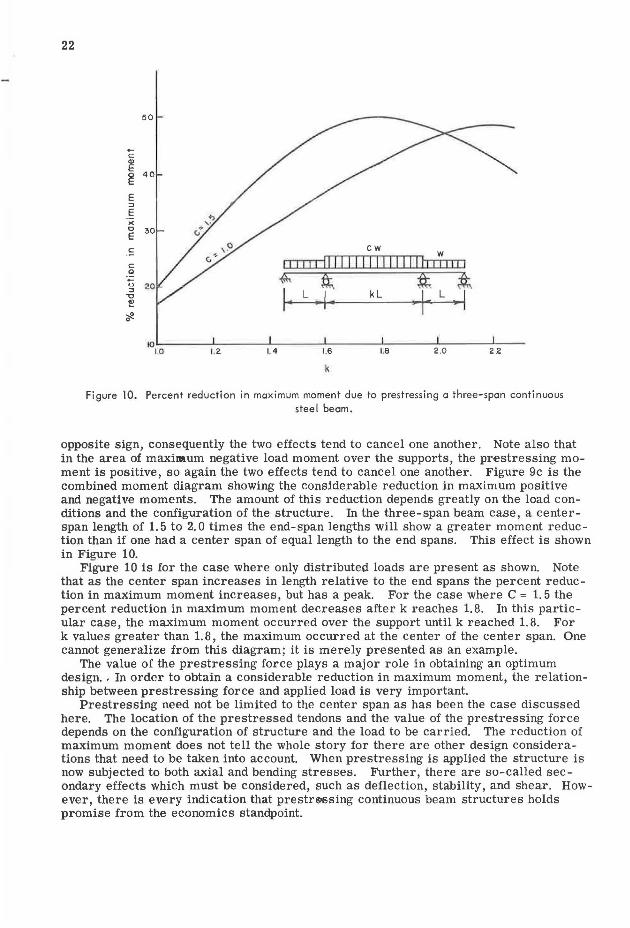
Figure 10. Percent reduction in maximum moment due to prestressing o three-span continuous steel beam.
opposite sign, consequently the two effects tend to cancel one another. Note also that in the area of maxilllum negative load moment over the supports, the prestressing moment is positive, so again the two effects tend to cancel one another. Figure 9c is the combined moment diagram showing the considerable reduction in maximum positive and negative moments. The amount of this reduction depends greatly on the load conditions and the configuration of the structure. In the three-span beam case, a centerspan length of 1. 5 to 2. 0 times the end-span lengths will show a greater moment reduction than if one had a center span of equal length to the end spans. This effect is shown in Figure 10.
Figure 10 is for the case where only distributed loads are present as shown. Note that as the center span increases in length relative to the end spans the percent reduction in maximum moment increases, but has a peak. For the case where C = 1. 5 the percent reduction in maximum moment decreases after k reaches 1. 8. In this particular case, the maximum moment occurred over the support until k reached 1.8. For k values greater than 1.8, the maximum occurred at the center of the center span. One cannot generalize from this diagram; it is merely presented as an example.
The value of the prestressing force plays a major role in obtaining an optimum design .. In order to obtain a considerable reduction in maximum moment, the relationship between prestressing force and applied load is very important.
Prestressing need not be limited to the center span as has been the case discussed here. The location of the prestressed tendons and the value of the prestressing force depends on the configuration of structure and the load to be carried. The reduction of maximum moment does not tell the whole story for there are other design considerations that need to be taken into account. When prestressing is applied the structure is now subjected to both axial and bending stresses. Further, there are so-called secondary effects which must be considered, such as deflection, stability, and shear. However, there is every indication that prestr<9Ssing continuous beam structures holds promise from the economics standpoint.
23
18'
3'
: • .: ,:< ·,· · .. ~· , hoop connectors .. :,·: · : ·, ·. ' · concrete deck ,: . :l :. ~ ~ ~ ~ ~: :, :':·o'".- .-. -l-::-\ -; ,- !- ,- , - ------+--,1'----------¥'----'-......;..----, -.. -. "-. -.-.. -., -,-.. -,,.-l
- V 10 '1211 ~ • '•, ::•., ._~.-;.~\ ; • (; •"' 0,: :~
s' 2'- 6 11
q_ beam
4 ' 4' - 4~/
prestressing cables
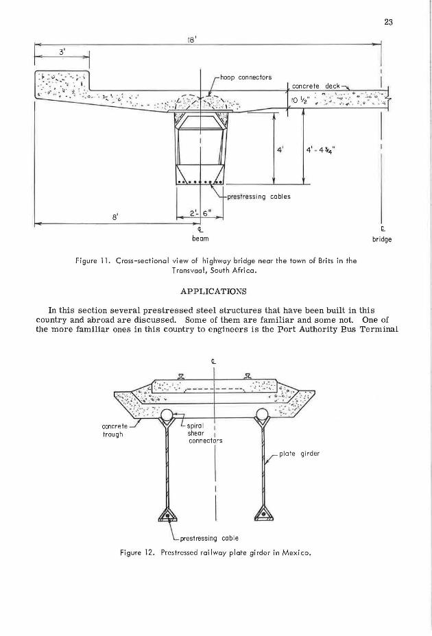
Figure 11. Cross-sectional view of highway bridge near the town of Brits in the Transvaal, South Africa.
APPLICATIONS
t bridge
In this section several prestressed steel structures that have been built in this country and abroad are discussed. Some of them are familiar and some not. One of the more familiar ones in this country to engineers is the Port Authority Bus Terminal
,----------
spiral shear 1 connectors
plate girder
• prestressing coble
Figure 12. Prestressed railway plate girder in Mexico.
rt
H
711
pr
es,t
ress
ed
con
cre
te
sla
b
'l:~·,
a·•· ..
•
: Q
:, .. ~
... ••I
I I I I
I I FL
I
I I 2
1x,4
I
/ /
ll!x
5 ,8
x9,'
~o
" )
'IFL
l'I 1ft.
]
I 21
x1 ,4
I
21x5 r
ax9
'-o
" TT
11 I I I
I~
I I
21x
1 ,4 l
I
I
I I
lh
fil, I
I I/
Ls3
-x2
-x
-2
2 4
15
'-4
"
:1i1
AD~
rr:n L'A
nch
ora
ge
14
).r'
-8"W
:-C
ol.
I ~I
I:~ I d
ib
4 L
pre
stre
sse
d
wir
es -
ult
. str
. =
24
0 k
si
21
'-4
"
1-7'
-o" e
ffe
cti
ve
sl
ab
-i ;o
_ ...
~
••
C,
·"··.
we
lde
d
pla
te g
ird
er
A-3
6
ste
el
... ~:
•o ._
;,c.•
.•
<.·
.·
, I
I I
Ls 3
: 2 x
22
x 4
21 X
_l 4 1•
16 -
4 w
ires
e
ach
sid
e
-lo
ad
= 1
00 K
,sid
e
12x
.!. 2
Sec
. A
-A
111
I lrt
I I
I I
m
8 C
18.
7
4tJL
4
l'I 11 1
Sec
. 8
-B
15
'-4
"
... ,-
c;~ .;
;~
• ..
•. !:
.
C 1
8.7
5 ~
21
xe
~.'-
91ol
:•
.. :
C"'·:;
.·I,!'
11 I
I !
I II
I I:
~!~
"I·:
-YV--
Fig
ure
13.
Th
ree-
span
co
nti
nu
ou
s pr
estr
esse
d st
eel
gir
der
in
O
akla
nd
, C
alif
orn
ia,
apar
tmen
t b
uid
lin
g.
I\;)
,I
>-
0 I
C\J
0 I
-v
2'- 6 11
" -. " . .. \ _ .......... . .
It. 42x.!. 2
3 28 XS
I I i-;---ft. 72x 2 x5
I" c, 36-2 tendons encased
in concrete
I 24 x 2
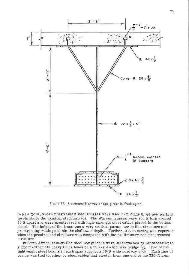
Figure 14. Prestressed highway bridge girder in Washington.
25
in New York, where prestressed steel trusses were used to provide three new parking levels above the existing structure (6). The Warren trusses were 200 ft long spaced 50 ft apart and were prestressed wifii high-strength steel cables placed in the bottom chord. The height of the truss was a very critical parameter in this structure and prestressing made possible the shallower depth. Further, a cost saving was reported when the prestressed structure was compared with the preliminary non-prestressed structure.
In South Africa, thin-walled steel box girders were strengthened by prestressing to support extremely heavy truck loads on a four-span highway bridge (7). Two of the lightweight steel beams in each .span support a 36-ft wide roadway deck. Each line of beams was tied together by steel cables that stretch from one end of the 330-ft long
26
bridge to the other. The beams were fabricated from ¼-in. steel plate, and were 82 ft 6 in. long, 3 ft wide, 4 ft 6 in. deep and weighed 24,000 lb. Each girder was prestressed with nine cables, each of which comprised 12 strands of 0. 276-in. diameter wire. The wires were placed in steel tubes and fixed to the girder ends. The Freqssinent system was used to prestress the cables in the shop to a total force of 360 tons. A sketch of the cross section of the bridge is shown in Figure 11.
In Mexico, a prestressed steel girder railway bridge was constructed across a canyon (8 ). Delta-style welded plate girders acting compositely with a concrete slab were utiilzed as shown in Figure 12.
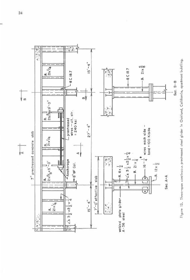
In California, a three-span continuous prestressed steel girder was used to support a three-story apartment building above the basement parking lot (9 ). The middle span of each girder was prestressed with high-strength steel wires as shown in Figure 13. Each girder was designed for composite action with the 7-in. concrete slab. A prestressing force of 200 kips per girder was selected to reduce the tension in the concrete in the negative moment region over the columns from 640 psi to 358 psi in order to minimize cracking of the concrete. The prestressing force reduced the tensile stress in the bottom flange at the center of the middle span from 27,500 psi to 17,200 psi and reduced the compressive stress in the bottom flange at the column from 24,200 psi to 17,200 psi.
Across the Nooksack River near Deming, Washington, a pair of 150-ft long prestressed steel delta-style welded plate girders acting compositely with a concrete slab provide the main supporting elements for a two-lane highway bridge (10). Each 6-ft girder weighs 36. 5 tons, which is less than half that of a comparable prestressed concrete girder, and the depth is about 12 in. less than that of a comparable all-steel girder. A cross-sectional view of one girder is shown in Figure 14. This structure is another example of the economy in prestressing composite steel beams.
There are many other such examples that could be discussed, such as Professor Magnel's prestressed trusses at Melsbrock Airport in Brussels (the old iron truss with rod and turnbuckle was a very early application of prestressing) and the Pan American passenger terminal at Kennedy Airport in New York; however, the application of prestressing is clear.
SUMMARY In this paper the nature of prestressed steel beam structures has been discussed.
The presentation has been limited to the type of prestressing which is applied by cables, wires or rods. There is reason to believe, as has been pointed out here, that this type of construction has many practicable applications and should be considered along with other types of solutions to a given problem. There are still many problems of design such as deflection and lateral stability that need special attention in this type of construction, and it is hoped through programs of research many of these questions will be answered. This type of structure has proven to be the solution in cases of medium to long spans carrying heavy loads where depth must be kept to a minimum, which indicates that the use of the prestressing principle applied to steel structures is most promising.
REFERENCES 1. Zollman, C. C. Prestressing Structural Steel. Military Engineer, Jan.-Feb. 1961. 2. Prestressed Steel Beams Replace Concrete. Steel Construction Digest, Amer. Inst.
of steel Const., Vol. 18, No. 2, 1961. 3. Prestressing Steel Stringers Reduces Bridge Weight by 25%. Engineering News
Record, Oct. 19, 1961. 4. Barnett, R. L. Prestressed Truss-Beams. Trans. ASCE, Vol. 124, 1959. 5. Hoadley, P. G. Behavior of Prestressed Composite Steel Beams. Jour. Struct.
Div., ASCE, Vol. 89, No. ST3, June 1963. 6. Cetra, M. A. Bus Terminal Extended Upward Three Stories. Civil Engineering,
ASCE, Oct. 1961.
27
7. Prestressed Steel Makes A Bridge. Engineering News-Record, Nov. 5, 1964. 8. Engineering News-Record, Dec. 14, 1961. 9. Prestressed Steel Girders Carry Prestressed Concrete Floor. Engineering News
Record, March 26, 1964. 10. Bridge Girders Blend Steel and Concrete. Engineering News-Record, April 7,
1966.
Related Documents