The missing half of the subduction factory: shipboard results from the Izu rear arc, IODP Expedition 350 Cathy J. Busby a , Yoshihiko Tamura b , Peter Blum c , Gilles Guèrin d , Graham D. M. Andrews e , Abigail K. Barker f , Julien L. R. Berger g , Everton M. Bongiolo h , Manuela Bordiga i , Susan M. DeBari j , James B. Gill k , Cedric Hamelin l , Jihui Jia m , Eleanor H. John n , Ann-Sophie Jonas o , Martin Jutzeler p , Myriam A. C. Kars q , Zachary A. Kita r , Kevin Konrad s , Susan H. Mahony t , Michelangelo Martini u , Takashi Miyazaki b , Robert J. Musgrave v , Debora B. Nascimento h , Alexander R. L. Nichols w , Julia M. Ribeiro x , Tomoki Sato b , Julie C. Schindlbeck y , Axel K. Schmitt z , Susanne M. Straub aa , Maryline J. Mleneck-Vautravers ab and Alexandra Yang Yang ac a Department of Earth and Planetary Sciences, University of California Davis, Davis, CA, USA; b Research and Development Center for Ocean Drilling Science, Japan Agency for Marine-Earth Science and Technology (JAMSTEC), Yokosuka, Japan; c International Ocean Discovery Program, Texas A&M University, College Station, TX, USA; d Lamont-Doherty Earth Observatory of Columbia University, Palisades, NY, USA; e Department of Geology & Geography, West Virginia University, Morgantown, WV, USA; f Institute of Earth Sciences, Uppsala University, Uppsala, Sweden; g Géosciences Environnement Toulouse (GET), Observatoire de Midi-Pyrénées, CNRS, IRD, Université Paul Sabatier, Toulouse, France; h Departamento de Geologia, Universidade Federal do Rio de Janeiro, Rio de Janeiro, Brazil; i Department of Earth Science, Paleobiology, Uppsala University, Uppsala, Sweden; j Department of Geology, Western Washington University, Bellingham, WA, USA; k Earth and Planetary Sciences, University of California Santa Cruz, Santa Cruz, CA, USA; l Centre for Geobiology, University of Bergen, Bergen, Norway; m Department of Urban Management, Kyoto University, Kyoto, Japan; n School of Geography, Earth Science and Environment, University of the South Pacific, Suva, Fiji; o Department of Organic Geochemistry, Institute of Geosciences, Christian-Albrechts-Universität zu Kiel, Kiel, Germany; p School of Physical Sciences and Centre of Excellence in Ore Deposits (CODES), University of Tasmania, Hobart, TAS, Australia; q Center for Advanced Marine Core Research, Kochi University, Nankoku, Japan; r Department of Earth and Atmospheric Sciences, University of Nebraska Lincoln, Lincoln, NE, USA; s College of Earth, Ocean and Atmospheric Sciences, Oregon State University, Corvallis, OR, USA; t Department of Earth Sciences, University of Bristol, Bristol, UK; u Instituto de Geología, Universidad Nacional Autónoma de México, Mexico, D.F., Mexico; v School of Geosciences, The University of Sydney, Sydney, NSW, Australia; w Department of Geological Sciences, University of Canterbury, Christchurch, New Zealand; x Department of Earth Science, Rice University, Houston, TX, USA; y GEOMAR Helmholtz Center for Ocean Research Kiel, Kiel, Germany; z Institute of Earth Sciences, Heidelberg University, Heidelberg, Germany; aa Geochemistry Division, Lamont-Doherty Earth Observatory of Columbia University, Palisades, NY, USA; ab Godwin Laboratory for Paleoclimate Research, Department of Earth Sciences, University of Cambridge, Cambridge, UK; ac Guangzhou Institute of Geochemistry, Chinese Academy of Sciences, Guangzhou, Guangdong, China ABSTRACT IODP Expedition 350 was the first to be drilled in the rear part of the Izu-Bonin, although several sites had been drilled in the arc axis to fore-arc region; the scientific objective was to understand the evolution of the Izu rear arc, by drilling a deep-water volcaniclastic section with a long temporal record (Site U1437). The Izu rear arc is dominated by a series of basaltic to dacitic seamount chains up to ~100-km long roughly perpendicular to the arc front. Dredge samples from these are geochemically distinct from arc front rocks, and drilling was undertaken to understand this arc asymmetry. Site U1437 lies in an ~20-km-wide basin between two rear arc seamount chains, ~90-km west of the arc front, and was drilled to 1804 m below the sea floor (mbsf) with excellent recovery. We expected to drill a volcaniclastic apron, but the section is much more mud-rich than expected (~60%), and the remaining fraction of the section is much finer-grained than predicted from its position within the Izu arc, composed half of ashes/tuffs, and half of lapilli tuffs of fine grain size (clasts <3 cm). Volcanic blocks (>6.4 cm) are only sparsely scattered through the lowermost 25% of the section, and only one igneous unit was encountered, a rhyolite peperite intrusion at ~1390 mbsf. The lowest biostratigaphic datum is at 867 mbsf (~6.5 Ma), the lowest palaeomagnetic datum is at ~1300 mbsf (~9 Ma), and the rhyolite peperite at ~1390 mbsf has yielded a U–Pb zircon concordia intercept age of (13.6 + 1.6/-1.7) Ma. Both arc front and rear arc sources contributed to the fine-grained (distal) tephras of the upper 1320 m, but the coarse-grained (proximal) volcani- clastics in the lowest 25% of the section are geochemically similar to the arc front, suggesting arc asymmetry is not recorded in rocks older than ~13 Ma. ARTICLE HISTORY Received 4 February 2017 Accepted 4 February 2017 KEYWORDS International Ocean Discovery Program; Izu-Bonin-Marianas arc; island arcs; magmatic arcs; rear arc; Japanese volcanoes CONTACT Cathy J. Busby [email protected] Department of Earth and Planetary Sciences, University of California Davis, One Shields Avenue, Davis, CA 95616, USA INTERNATIONAL GEOLOGY REVIEW, 2017 http://dx.doi.org/10.1080/00206814.2017.1292469 © 2017 Informa UK Limited, trading as Taylor & Francis Group

Welcome message from author
This document is posted to help you gain knowledge. Please leave a comment to let me know what you think about it! Share it to your friends and learn new things together.
Transcript

The missing half of the subduction factory: shipboard results from the Izu reararc, IODP Expedition 350Cathy J. Busbya, Yoshihiko Tamurab, Peter Blumc, Gilles Guèrind, Graham D. M. Andrewse, Abigail K. Barkerf,Julien L. R. Bergerg, Everton M. Bongioloh, Manuela Bordigai, Susan M. DeBarij, James B. Gillk, Cedric Hamelinl,Jihui Jiam, Eleanor H. Johnn, Ann-Sophie Jonaso, Martin Jutzelerp, Myriam A. C. Karsq, Zachary A. Kitar, Kevin Konrads,Susan H. Mahonyt, Michelangelo Martiniu, Takashi Miyazakib, Robert J. Musgravev, Debora B. Nascimentoh,Alexander R. L. Nicholsw, Julia M. Ribeirox, Tomoki Satob, Julie C. Schindlbecky, Axel K. Schmittz, SusanneM. Straubaa,Maryline J. Mleneck-Vautraversab and Alexandra Yang Yangac
aDepartment of Earth and Planetary Sciences, University of California Davis, Davis, CA, USA; bResearch and Development Center forOcean Drilling Science, Japan Agency for Marine-Earth Science and Technology (JAMSTEC), Yokosuka, Japan; cInternational OceanDiscovery Program, Texas A&M University, College Station, TX, USA; dLamont-Doherty Earth Observatory of Columbia University,Palisades, NY, USA; eDepartment of Geology & Geography, West Virginia University, Morgantown, WV, USA; fInstitute of Earth Sciences,Uppsala University, Uppsala, Sweden; gGéosciences Environnement Toulouse (GET), Observatoire de Midi-Pyrénées, CNRS, IRD,Université Paul Sabatier, Toulouse, France; hDepartamento de Geologia, Universidade Federal do Rio de Janeiro, Rio de Janeiro, Brazil;iDepartment of Earth Science, Paleobiology, Uppsala University, Uppsala, Sweden; jDepartment of Geology, Western WashingtonUniversity, Bellingham, WA, USA; kEarth and Planetary Sciences, University of California Santa Cruz, Santa Cruz, CA, USA; lCentre forGeobiology, University of Bergen, Bergen, Norway; mDepartment of Urban Management, Kyoto University, Kyoto, Japan; nSchool ofGeography, Earth Science and Environment, University of the South Pacific, Suva, Fiji; oDepartment of Organic Geochemistry, Instituteof Geosciences, Christian-Albrechts-Universität zu Kiel, Kiel, Germany; pSchool of Physical Sciences and Centre of Excellence in OreDeposits (CODES), University of Tasmania, Hobart, TAS, Australia; qCenter for Advanced Marine Core Research, Kochi University,Nankoku, Japan; rDepartment of Earth and Atmospheric Sciences, University of Nebraska Lincoln, Lincoln, NE, USA; sCollege of Earth,Ocean and Atmospheric Sciences, Oregon State University, Corvallis, OR, USA; tDepartment of Earth Sciences, University of Bristol,Bristol, UK; uInstituto de Geología, Universidad Nacional Autónoma de México, Mexico, D.F., Mexico; vSchool of Geosciences, TheUniversity of Sydney, Sydney, NSW, Australia; wDepartment of Geological Sciences, University of Canterbury, Christchurch, NewZealand; xDepartment of Earth Science, Rice University, Houston, TX, USA; yGEOMAR Helmholtz Center for Ocean Research Kiel, Kiel,Germany; zInstitute of Earth Sciences, Heidelberg University, Heidelberg, Germany; aaGeochemistry Division, Lamont-Doherty EarthObservatory of Columbia University, Palisades, NY, USA; abGodwin Laboratory for Paleoclimate Research, Department of Earth Sciences,University of Cambridge, Cambridge, UK; acGuangzhou Institute of Geochemistry, Chinese Academy of Sciences, Guangzhou,Guangdong, China
ABSTRACTIODP Expedition 350 was the first to be drilled in the rear part of the Izu-Bonin, although severalsites had been drilled in the arc axis to fore-arc region; the scientific objective was to understand theevolution of the Izu rear arc, by drilling a deep-water volcaniclastic section with a long temporalrecord (Site U1437). The Izu rear arc is dominated by a series of basaltic to dacitic seamount chainsup to ~100-km long roughly perpendicular to the arc front. Dredge samples from these aregeochemically distinct from arc front rocks, and drilling was undertaken to understand this arcasymmetry. Site U1437 lies in an ~20-km-wide basin between two rear arc seamount chains, ~90-kmwest of the arc front, and was drilled to 1804 m below the sea floor (mbsf) with excellent recovery.We expected to drill a volcaniclastic apron, but the section is much more mud-rich than expected(~60%), and the remaining fraction of the section is much finer-grained than predicted from itsposition within the Izu arc, composed half of ashes/tuffs, and half of lapilli tuffs of fine grain size(clasts <3 cm). Volcanic blocks (>6.4 cm) are only sparsely scattered through the lowermost 25% ofthe section, and only one igneous unit was encountered, a rhyolite peperite intrusion at~1390 mbsf. The lowest biostratigaphic datum is at 867 mbsf (~6.5 Ma), the lowest palaeomagneticdatum is at ~1300 mbsf (~9 Ma), and the rhyolite peperite at ~1390 mbsf has yielded a U–Pb zirconconcordia intercept age of (13.6 + 1.6/−1.7) Ma. Both arc front and rear arc sources contributed tothe fine-grained (distal) tephras of the upper 1320 m, but the coarse-grained (proximal) volcani-clastics in the lowest 25% of the section are geochemically similar to the arc front, suggesting arcasymmetry is not recorded in rocks older than ~13 Ma.
ARTICLE HISTORYReceived 4 February 2017Accepted 4 February 2017
KEYWORDSInternational OceanDiscovery Program;Izu-Bonin-Marianas arc;island arcs; magmatic arcs;rear arc; Japanese volcanoes
CONTACT Cathy J. Busby [email protected] Department of Earth and Planetary Sciences, University of California Davis, One Shields Avenue,Davis, CA 95616, USA
INTERNATIONAL GEOLOGY REVIEW, 2017http://dx.doi.org/10.1080/00206814.2017.1292469
© 2017 Informa UK Limited, trading as Taylor & Francis Group

Introduction
This article provides an overview of shipboard resultsfrom one of three closely related International OceanDiscovery Program (IODP) expeditions carried out insequence in the Izu-Bonin-Mariana (IBM) arc system in2014 (Figure 1). It is meant to reach a wider audiencethan the scientific ocean drilling community, by pre-senting shipboard results in a compact and accessiblemanner, focusing on geologic results that will be ofinterest to those working in magmatic arcs on conti-nents as well as those in the sea. More sophisticatedgeochemical results will be reported in future papers,using shore-based techniques; this article focuses ongeologic observations, which will not change. We referthose seeking much greater detail to the Proceedings ofthe International Ocean Discovery Program, Expedition350; all of the figures presented here appear in thatvolume, along with hundreds more (Tamura et al.2015a, 2015d).
Expedition 350 was the first expedition to drill in theIzu rear arc; all previous IODP/ODP sites were drilled inor near the Izu-Bonin arc front or fore-arc (Figure 2),leading to an incomplete view of Izu arc magmatism.Thus, the main objective of Expedition 350 was toreveal the history of ‘the missing half’ of the subductionfactory (Tamura et al. 2013). The second expedition(351) focused on IBM arc origins by drilling west ofthe Kyushu-Palau Ridge (Figure 1), where it was inferredthat the foundation, origin, and early evolution of theIBM arc are recorded (Arculus et al. 2013, 2015). Thethird expedition (352) examined the processes of sub-duction initiation, by drilling the outer IBM fore-arc(Figure 1; Pearce et al. 2013; Reagan et al. 2015).
The goal of Expedition 350 was to core and log onesite on the Izu rear arc, Site U1437 (Figure 1). This sitewas chosen to provide a temporal record of rear-arcmagma compositions, ideally from Palaeogene toNeogene time, allowing comparison with the previouslydrilled fore-arc magmatic record and determination ofacross-arc geochemical variations throughout the his-tory of the arc system. In addition to drilling in the reararc, Expedition 350 also drilled a 150 m deep geotech-nical hole in the fore-arc (Site U1436, Figure 1) forpotential deep drilling; this site was chosen partly onthe basis of results gotten from ODP Site 792, which isonly 1.5 to the east of site U1436 (Tamura et al. 2015a).ODP Site 792 was drilled to 886 m below the sea floor(mbsf,) and the stratigraphy of its upper 150 m (Taylorand Fujioka et al. 1990) is very similar to that of SiteU1436. Core from these sites yielded a rich record oflate Pleistocene explosive volcanism (Tamura et al.2015c), but is not discussed further here, for space
considerations. This article focuses on Site U1437,which was cored at 1776 m below sea level (mbsl) to
0 500
km
130°E 135° 140° 145°
10°
15°
20°
25°
30°
35°N
PalauIslands
Pacific plate
OgasawaraPlateau
Mar
iana
arc
Mar
iana
Tro
ugh
Wes
t Mar
iana
Rid
ge
PareceVelaBasin
ShikokuBasin
Kyu
shu-
Pal
au R
idge
AmamiPlateau
Daito RidgeOki-Daito Ridge
WestPhilippineBasin
Bon
in R
idge
Izu
arc
Bon
in a
rc
Fore-arc high/Shin-Kurose Ridge
U1436
U1437
Sof
ugan
Tec
toni
c Li
ne
EXP 351
EXP 352
Figure 1. Tectonic setting of IBM arc (from Taylor 1992; Tamuraand Tatsumi 2002). The IBM arc-trench system forms the conver-gent margin between the Pacific and Philippine Sea plates. Shownhere are bathymetric features of the eastern Philippine Sea, IBM arcsystem, and Expedition 350 (Site U1436 in fore-arc and Site U1437in rear arc) and Expedition 351 and 352 site locations (EXP). Dashedlines = wide-angle seismic profiles; the north–south seismic profiles(along the present-day arc front and rear arc ~150 km west of thearc front) are shown in Figure 4. Lines of circles = conspicuousnorth–south rows of long-wavelength magnetic anomalies, attrib-uted to loci of Oligocene magmatic centres by Yamazaki and Yuasa(1998). Site U1436 is on the fore-arc anomaly (fore-arc high/Shin-Kurose Ridge); Site U1437 is on the rear-arc anomaly (Nishi-shichitoRidge). The boundary between the Izu arc and the Bonin arc lies atthe Sofugan Tectonic Line, discussed further in Figure 4. Figurereprinted from Proceedings of the International Ocean DiscoveryProgram, Expedition 350 (Tamura et al. 2015a) with permissionfrom IODP.
2 C. J. BUSBY ET AL.

a depth of 1806.5 mbsf, through a volcaniclastic succes-sion, with excellent core recovery (Holes U1437 B, D,and E overall: 55%, 74%, and 62%). This provided atime-integrated view of the rear arc over the past~14 million years.
Major questions addressed by drilling the Izu rear arcinclude the following: (1) Izu rear arc volcanoes differfrom arc front volcanoes by being more similar to aver-aged continental crust (i.e. enriched in alkalis, Ba, Th, U,and LREE). The Izu rear arc is, therefore, important forunderstanding how arc magmas and intracrustal differ-entiation produce crust that is similar in composition tothe ‘averaged continental crust’. When did this arcasymmetry develop? (2) What kinds of basins accom-modated the volcaniclastic succession we drilled? (3)What eruption, transport and depositional processesare recorded in the rear arc volcaniclastic successiontargeted for drilling, and what kinds of depositionalenvironments are represented by the succession?
Evolution of the IBM arc system
The IBM arc (Figure 1) has formed in response to sub-duction of the Pacific plate over the past 52 million year(Stern et al. 2003). Subduction began as part of a hemi-sphere-scale foundering of old, dense lithosphere in thewestern Pacific (Bloomer et al. 1995; Cosca et al. 1998).During the subduction initiation stage (~52–47 Ma)investigated by Expedition 352 (Figure 1), igneous activ-ity successively produced low-K mid-ocean-ridge basalt(MORB)-like tholeiite, boninite, and subordinate low-Krhyolite across the region that now lies in the fore-arc(cf. Reagan et al. 2015). This suggests that sinking of the
downgoing plate was rapidly followed by an episode ofasthenospheric upwelling and melting, sometimesenhanced by solute-bearing water fluxes releasedfrom the downgoing plate, over a zone that was thou-sands of kilometres long and as wide as 200 km(Reagan et al. 2010). As subduction proceeded, hydrousmantle melting overprinted decompression mantlemelting, establishing the first mature arc in Eocene toOligocene time, referred to as the Kyushu-Palau arc(Taylor 1992; Ishizuka et al. 2006a, 2006b, 2011), hereinalso referred to as the Palaeogene arc.
By ~25 Ma, rifting began along the length of theKyushu-Palau arc and opening of the Shikoku Basinisolated the rear-arc volcanoes from the arc-front volca-noes (Ishizuka et al. 2011; Figure 1), producing theKyushu-Palau Ridge remnant arc, which has Eoceneand Oligocene rear-arc rocks (see Expedition 351 site,Figure 1). Seafloor spreading of the Shikoku and PareceVela Basins (Figure 1) at ~25–17 Ma was likely accom-panied by a hiatus in arc magmatism, but the fore-arcsedimentary record shows that arc-front volcanismresumed by ~17 Ma (Stern et al. 2003), referred to asthe Neogene arc, or the IBM arc (Ishizuka et al. 2011).
The Neogene IBM arc front is inferred to lie in nearlythe same position as the Palaeogene arc front (Ishizukaet al. 2011); however, pre-Quaternary rocks have notbeen recovered from the IBM arc front, perhapsbecause they are buried or were partly remelted and/or remobilized during the Quaternary. In contrast, theIzu rear arc (Figures 1 and 3) has not been extensivelyburied or modified by Quaternary magmatic processes,so Neogene rocks are well preserved; these are domi-nated by ~17–3 Ma NE-trending rear-arc seamount
138°E 139° 140° 141° 142°
791 792 793 786
km
10
20
30
ShikokuBasin
Riftbasin
Arc front
Fore-arc basin
BON
Outer-arc high Shinkai dives
7.8
7.57.1-7.3
6.0-6.3 6.56
7<5FAB
?
Serpentiniteseamounts
Hydratedlow-Vmantle
Trenchaxis
Rear arc
km
10
20
30
U1437 U1436
0 100
km
Figure 2. Wide-angle seismic profile across the Izu arc, with P-wave velocities for upper, middle, and lower crust (greens) and formantle (blues) (Suyehiro et al. 1996). ODP (black) and IODP (red) sites are projected onto this line of section. Site U1437 is the firstsite drilled in the broad region of long-lived rear-arc seamount chains (shown in Figure 3). ODP Site 791 is also in the rear arc, but itis located in the narrow, young, and active Sumisu rift. Site U1436 and ODP Sites 792, 793, and 786 are in the modern fore-arc basin.BON = boninite, FAB = fore-arc basalt. Figure reprinted from Proceedings of the International Ocean Discovery Program, Expedition350 (Tamura et al. 2015a) with permission from IODP.
INTERNATIONAL GEOLOGY REVIEW 3

chains described in the following. The Marianas seg-ment of the IBM arc (Figure 1) differs from the Izusegment by lacking the rear-arc seamount chains;
instead, a new episode of arc rifting began at ~7 Ma,resulting in opening of the Mariana Trough back-arcbasin by seafloor spreading at ~3–4 Ma (Yamazaki andStern 1997). Rifting of the Izu arc began at ~3 Mabehind the arc front (Figure 3).
We know more about the Neogene history of theIBM arc than we do about its Palaeogene history; yet itis thought that most of the IBM crust was generated inthe Palaeogene (Eocene–Oligocene; Kodaira et al. 2008).Furthermore, silicic volcanoes of the Quaternary arcfront and Miocene granitic rocks in the Izu collisionzone on Honshu are inferred to have formed by meltingof Eocene–Oligocene arc crust (Tamura et al. 2009,2010). As discussed in the following, Neogene rhyolitevolcanism may be more important in the Izu rear-arcseamount chain than previously thought and couldhave resulted from melting of Palaeogene ‘arc base-ment’. For this reason, we will now review the evidencefor Palaeogene arc basement highs in the Izu arc anddiscuss constraints on their age and origin.
Palaeogene arc basement highs in the Izu arc
Magnetic and seismic surveys indicate that both IODPSites U1436 and U1437 lie along buried north–southridges that consist of magmatic crystalline rocks, whichare inferred to be Oligocene–Eocene (Palaeogene) inage. Three conspicuous, approximately north–southrows of long-wavelength magnetic anomalies wereidentified by Yamazaki and Yuasa (1998) in the Izu-Bonin arc system and attributed to loci of middle- tolower-crustal magmatic bodies (Figure 1):
● The western north–south anomaly corresponds tothe Kyushu-Palau Ridge, where Eocene andOligocene lava was dredged; these have rear-arcgeochemical affinity, and are interpreted as rear-arc magmas rifted off the Palaeogene arc duringthe opening of the Shikoku Basin (Kodaira et al.2008; Ishizuka et al. 2011).
● The eastern north–south anomaly lies in the mod-ern fore-arc near the arc front and corresponds tothe Shin-Kurose Ridge (Figure 1) (Yamazaki andYuasa 1998), also referred to as the Izu fore-archigh (Taylor and Fujioka et al. 1990). The Shin-Kurose Ridge/fore-arc high forms a bathymetrichigh in the northern Izu arc and is buried beneathOligocene to Quaternary volcaniclastic and sedi-mentary rocks in the southern Izu arc, at OceanDrilling Program (ODP) Site 792 and Site U1436.Andesite lava in the lowermost 82 m at Site 792was referred to as ‘Oligocene basement’, on thebasis of K/Ar ages (Taylor and Fujioka et al. 1990;
Figure 3. Volcano-tectonic domains within Izu arc. The well-defined arc front is formed by a ~north–south chain of islandvolcanoes, the largest of which are named here. Arc crust underliesthe rear arc, whereas the Shikoku Basin (Figure 1), which forms thewestern boundary of the rear arc, is floored by oceanic crust. Therear arc is divided into two tectonic zones, from west to east (alsooldest to youngest): (1) rear-arc seamount chains (~100-km long;~17–3Ma) which trend at a high angle to the arc front and span thecompositional range from basalt to rhyolite, and (2) extensionalzone (~100-km wide, <3 Ma), overlapping the eastern half of therear-arc seamount chains, and characterized by ~north–south nor-mal faults with small bimodal volcanoes (backarc knolls). Along theeasternmargin of the extensional zone, immediately behind the arcfront, lies a narrow active rift (<1 Ma), with north–south rift basinsand bimodal volcanism. Volcanic rocks in the extensional zone andthe active rift are referred to as rift-type magmas, and those in therear-arc seamount chains are referred to as rear-arc seamount chain-type magmas. White stars = Site U1436 (fore-arc) and Site U1437(rear arc). Box = area of Figure 7.
4 C. J. BUSBY ET AL.

Taylor 1992), but more recent 40Ar/39Ar datingshow these are Eocene (Ishizuka et al. 2011).
● The central north–south magnetic anomaly liesburied in the Izu rear arc (Figure 1) and is referredto as the Nishi-shichito Ridge (Figure 4) (Yamazakiand Yuasa 1998). This basement high has not beendrilled and was one of the objectives of Expedition350. Kodaira et al. (2008) ran a wide-angle seismicprofile along the length of the rear-arc Nishi-shi-chito Ridge and compared it to a wide-angle seis-mic profile made along the length of the arc frontby Kodaira et al. (2007a, 2007b) (Figure 4). Theydivided the arc front into segments based onvariations in the thickness of middle crust anddid the same for the rear-arc Nishi-shichito Ridge.They concluded that although the thickness of themiddle crust for each rear-arc segment is smallerthan the thickness in the arc front, the bulk com-positions of the crust segments are inferred to bethe same, on the basis of seismic properties..Furthermore, they used the match on middle crus-tal thicknesses to infer that the Nishi-shichitoRidge is a ‘palaeo-arc’ that obliquely rifted off thearc front in an extension direction parallel to thenortheast–southwest Sofugan Tectonic Line(Figure 1). The Sofugan Tectonic Line is theboundary between the Izu and Bonin arc seg-ments (Figure 1); south of it lies the prominent
Bonin Ridge and the deep fault-boundedOgasawara Trough to the west, produced byEocene to early Oligocene arc magmatism andback-arc extension, respectively. Both the promi-nent arc ridge and the fault-controlled back-arcbasin are absent north of the Sofugan Tectonic
Figure 4. Wide-angle seismic profiles (Kodaira et al. 2008) showing middle-crust thickness variations in two transects: one along thearc front and one along the rear-arc Nishi-shichito Ridge; the positions of these lines are shown as lines of circles on Figure 1. The6.0–6.8, 7.1–7.3, and 7.8 km/s layers (see P wave velocity on key) correspond to middle crust, lower crust, and upper mantle,respectively. Based on variations in middle-crust thickness in these profiles, Kodaira et al. (2008) infer that rear-arc crust wasobliquely rifted off the arc front, probably during the opening of the Shikoku and Parece Vela Basins (~25 Ma; Figure 1). Quaternarybasalt-dominant island volcanoes on the arc front: Mi = Miyakejima, Ha = Hachijojima, Ao = Aogashima, Su = Sumisu Caldera,To = Torishima; andesite Oligocene volcano east of arc front: Om = Omachi Seamount. ODP Sites 787, 792, and 793 also shown.Figure reprinted from Proceedings of the International Ocean Discovery Program, Expedition 350 (Tamura et al. 2015a) withpermission from IODP.
NE Japan
Volcanoes
Man
tlew
edge
Cru
st
Subducting plate
Japan Trench
Hot fingers in the mantle wedge
Figure 5. Hot fingers hypothesis of Tamura et al. (2002) proposedfor northeast Japan and adapted here for the origin of Izu rear-arcseamount chains. Hypothetically, mantle convection above thesubducting slab produces finger-like hot regions in the mantlewedge below the rear-arc plate. These hot regions extend towardsthe arc front with time, suggesting younging of rear-arc seamountsfrom west to east. Figure reprinted from Proceedings of theInternational Ocean Discovery Program, Expedition 350 (Tamuraet al. 2015a) with permission from IODP.
INTERNATIONAL GEOLOGY REVIEW 5

Line, so we infer that the Sofugan Tectonic Lineoriginated as an accommodation fault between aregion of high extension to the south and little orno extension to the north. Kodaira et al. (2008)propose that oblique rifting of the Nishi-shichitoRidge palaeoarc off the arc front occurred duringthe opening of the Shikoku Basin, sometime after~30 Ma. If the oblique rifting model is correct, thecrystalline basement beneath Site U1437, notreached during Expedition 350, may representrear-arc crust but formed in a position much closerto the arc front than it is now; alternatively, it mayrepresent arc-front crust that has becomestranded in the rear arc by rifting. New seismicsurveys undertaken in preparation for drilling atSite U1437, described in the following, also sup-port the interpretation that the rear arc is under-lain by Palaeogene arc basement rocks.
Neogene rear-arc volcanism, Izu arc
We refer to all Neogene volcanic rocks behind the Izuarc front as rear-arc volcanic rocks. Rear-arc volcanicrocks (Figure 3) include (1) the ~17–3 Ma east NE-trend-ing basaltic to rhyolitic rear-arc seamount chains, (2) the<3 Ma bimodal back-arc knolls of the broad extensionalzone, and (3) the <1.5 Ma bimodal volcanic rocks of theactive rift immediately behind the arc front. Thus, Izurear-arc volcanism falls into two magmatic suites: the<3 Ma bimodal rift-type magmas and the ~17–3 Mabasalt to rhyolite rear-arc seamount-type magmas.Both types lie within the rear part of the arc (i.e. behindthe arc front) and lie on arc crust, although the western-most end of the rear-arc seamount chains lies onShikoku Basin oceanic crust. The bimodal rift-type mag-mas differ from both the arc front and the rear-arcseamount chains in trace element and radiogenic iso-topic ratios; this has been variably attributed to (1) atransition from flux to decompression mantle meltingas arc rifting commences, (2) a change in the characterof slab-derived flux, or (3) a change in the mantlesource through mantle wedge convection(Hochstaedter et al. 1990a, 1990b, 2001; Ishizuka et al.2003a, 2006b; Tollstrup et al. 2010).
The Izu rear-arc seamount chains are as long as ~80 kmand strike N60°E (Figure 3). The tops of the Izu rear-arcvolcanic chains were sampled by dredging, and theircompositions range from basalt to rhyolite (Ishizukaet al. 1998, 2003b; Hochstaedter et al. 2000). Three mainhypotheses have been proposed for the origin of theseamount chains:
(1) They are related to compression caused by colli-sion between the southwest Japan and Izu arcs,associated with opening of the Japan Sea (Karigand Moore 1975a; Bandy and Hilde 1983).
(2) They formed along Shikoku Basin transformfaults (Yamazaki and Yuasa 1998).
(3) They overlie diapirs in the mantle wedge, such asthe ‘hot fingers’ proposed for northeast Japan(Tamura et al. 2002), illustrated in Figure 5.
A striking characteristic of volcanic arcs is the asym-metry in geochemical characteristics with distance fromthe trench, which was known prior to the advent ofplate tectonics (Kuno 1959; Dickinson and Hatherton1967). Izu arc-front rocks are low-K, but the rear-arctype lava is medium to high-K (Gill 1981). Similarly,arc-front volcanic rocks are strongly depleted in incom-patible light rare earth elements (REEs) relative to themiddle and heavy REEs, whereas lava from rear-arcseamount chains is enriched in light REEs. On bothK2O versus SiO2 and REE plots, the composition of therear-arc seamount chain magmas is more similar to thecontinental crust composition than the arc-front mag-mas. Thus, the Izu rear-arc magmatism and crust forma-tion appears to be a better analogue to generatecontinental crust than the arc front (Tamura et al. 2013).
Site U1437 lies in an ~20-km wide basin in the lowarea between two major constructional volcanic ridges:the Manji and Enpo rear-arc seamount chains (Figure 3).It is therefore classified as a volcano-bounded intra-arcbasin, using the criteria elucidated by Smith and Landis(1995) (Figure 6). In contrast, the active rift to the eastof Site U1437 (Figure 3) is a fault-bounded intra-arcbasin, using the terminology of Smith and Landis(1995) (Figure 6). For simplicity, the volcano-boundedbasin bounded by the Enpo and Manji rear-arc sea-mount chains (Figure 7) is referred to as the Enpo-Manji volcano-bounded basin (Figure 8(c,d)). Similarly,we propose that future workers refer to other basinsbetween rear-arc seamount chains by the names of thechains that bound them (e.g. Genroku-Enpo Basin andManji-Kan’ei Basin, Figure 3).
New descriptive scheme for volcaniclastic rocks
Expedition 350 devised a new scheme for describingvolcaniclastic and associated nonvolcaniclastic sedi-ments, described in detail by Tamura et al. (2015b).The new scheme was devised to improve descriptionof volcaniclastic sediments and their mixtures with non-volcanic (siliciclastic, chemical, and biogenic) sedimentsbut maintain the usefulness of prior schemes fordescribing nonvolcanic sediments. The new scheme
6 C. J. BUSBY ET AL.

was devised to facilitate the understanding of volcano-sedimentary processes by making reproducible andquantifiable observations of volcanic input to the sedi-mentary record. Previous core descriptions (e.g. ODPLeg 126) obscured the importance of volcanic inputby referring to volcanic material (e.g. ashes/tuffs) assiliclastic material (e.g. sands/sandstone or tuffaceoussands/sandstones). The new classification scheme isbased entirely on observations that can be made byany scientist at the macroscopic and microscopic level,making the data more reproducible from user to user.Genetic inferences are not part of the descriptivescheme but can be added as comments to descriptiverecords if so desired. A very brief description of thescheme is presented here to allow the reader to under-stand our rock descriptions.
Four sedimentary lithologic classes were defined,including: (1) volcanic lithologic class, defined as >75%volcanic particles; (2) tuffaceous lithologic class, contain-ing 25–75% volcanic-derived particles mixed with non-volcanic particles; (3) nonvolcanic siliciclastic lithologicclass, containing <25% volcanic siliciclastic particles,where nonvolcanic siliciclastic particles dominate chemi-cal and biogenic particles; (4) biogenic lithologic class,containing <25% volcanic and nonvolcaniclastic siliciclas-tic and chemical particles. The principal name for
sediments and sedimentary rocks is based on grain sizeand is purely descriptive; it does not depend on inter-pretations of fragmentation, transport, or depositional oralteration processes. The sedimentary grain size classesof Wentworth (1922) are used for the nonvolcanic silici-clastic and tuffaceous lithologic classes, whereas thegrain size classes of Fisher and Schmincke (1984) areused for the volcanic lithologic class. The prefix ‘mono-mict’ was applied where clast compositions wererestricted to a single type and ‘polymict’ was appliedwhere clast compositions of multiple types were present.We adopted a new method to estimate the composi-tional range of volcanic clasts using three entries: ‘mafic’,‘evolved’ and a mixture of the two, termed ‘bimodal’. Inour macroscopic analyses, mafic versus evolved intervalswere defined by the greyscale index of the main particlecomponent, with mafic grains and clasts usually rangingfrom black to dark grey and evolved grains and clastsranging from dark grey to white. Microscopic examina-tion further aided in assigning the prefix ‘mafic’ or‘evolved’, using glass shard colour and mineralogy.Intervals we described as mafic are inferred to be basaltand basaltic andesite, and intervals we described asevolved were inferred to be intermediate and silicic incomposition; however, precise determination of bulkcomposition requires chemical analysis.
Volcano-bounded basin Fault-bounded basin
Volcaniclastic sediments
a
Volcanic rocks
b
Figure 6. Two main basin types recognized within arcs, as defined by Smith and Landis (1995). (a) Volcano-bounded basin: small,irregular basins between individual volcanoes; larger linear troughs between volcanic chains; and thick basin fill preserved only inoceanic arcs, below sea level. Low areas between the series of rear-arc seamount chains shown in Figure 3 are volcano-boundedbasins formed during growth of the chains between ~17 and 3 Ma. Site U1437 is located in one of these volcano-bounded basins,which we refer to as the Enpo-Manji Basin (Figures 7 and 8(c,d)). (b) Fault-bounded basin: rapidly subsiding basins that are deep (upto 10 km) and have very high sediment accumulation rates (~1 km/million year); they are found in continental and oceanic arcs. Afault-bounded basin is currently forming in the <1 Ma active rift west of the Izu arc front (Figure 3). Although the broader zone ofextension (<3 Ma) produced faults within the eastern halves of the volcano-bounded basins between the rear-arc seamount chains,including the basin drilled at Site U1437 (some visible on Figure 8(c,d)), the bounding volcanic chains (and not the <3 Maextensional zone faults) primarily controlled accommodation (Figure 8(c)). Figure reprinted from Proceedings of the InternationalOcean Discovery Program, Expedition 350 (Tamura et al. 2015a) with permission from IODP.
INTERNATIONAL GEOLOGY REVIEW 7

In summary, the new volcaniclastic descriptivescheme applied during Expedition 350 uses a morenongenetic approach than proposed by previousauthors because the sediments and rocks are namedbased on materials that are visible macroscopically andmicroscopically and not on the basis of inferred frag-mentation, transport, and depositional processes (i.e.pyroclasts, autoclasts, hydroclasts, epiclasts, andreworked volcanic clasts [Fisher and Schmincke 1984;Cas and Wright 1987; McPhie et al. 1993).
International Ocean Discovery Program SiteU1437
Site U1437 is located in the Izu rear arc and is ~330 kmwestof the axis of the Izu-Bonin Trench (Figures 1 and 2) and~90 km west of the arc-front volcanoes Myojinsho andMyojin Knoll (Figure 3) at 2117 mbsl between the Manjiand Enpo seamount chains (Figure 7). The stratigraphicsection shown in Figure 9 is a composite from three holesdrilled a few tens of metres apart using different techni-ques. The shallowest and least consolidated material waspenetrated at Hole U1437B (drilled using Advanced PistonCoring (APC), Half-Length Advanced Piston Corer (HLAPC),and Extended Core Barrel (XCB)). Deeper, more consoli-dated units were drilled at Holes U1437D and U1437Eusing the Rotary Core Barrel (RCB) (see http://iodp.tamu.edu/tools/for details about these tools). These differentdrilling techniques resulted in partial sampling of the sec-tion: In Hole U1437B we cored 439.1 m and recovered242.6 m (55% recovery). In Hole U1437D we cored677.4 m, with 503.8 m recovered (74%). In Hole U1437Ewe cored 702.5 m and recovered 387.45 m (55% recovery).Incomplete and disturbed cores are unfortunate butexpected; to ensure a more uniform perspective on thesection (including intervals that are not recovered incores), downhole logging is carried out before the hole iscased. Combined studies of cores andwell logs allowed theentire sequence to be interrogated. Most of the unconsoli-dated stratigraphy in Hole U1347B is well preserved andfew coring disturbances occur, allowing very good strati-graphic continuity. Drilling disturbances are present inHoles U1347D and U1347E, and vary depending on rocktype and consolidation.
Seismic surveys
Seismic surveys for Site U1437 are summarized brieflyhere. Numerous lines were shot in two different cam-paigns (Yamashita et al. 2017); parts of three seismicsections that cross at Site U1437 are plotted on Figure 7(c) and shown in Figure 8. Line IBr5 (Figure 8(a)) is thelongest seismic line, running east–west from the Manji
-4000
-4000
-3000
-3000
-3000
-2000
-2000-2000
-200
0
-200
0
-200
0
-100
0
-1000
-1000
-1000
-1000
-100
0
-100
0
-1000
1000
Aogashima
Myojin Knoll
Enpo
Manji
Kan’ei
0 50
km
IBM3-N
E5IBM
3-NW5
IBr5
Myojinsho
31°00'
31°30'
32°00'
32°30'N
138°00'E 138°30' 139°00' 139°30' 140°00'
b
31°00'
31°30'
32°00'
32°30'N
-4000
-4000
-3000
-3000
-3000
-2000
-2000-2000
-200
0
-200
0
-200
0
-100
0
-1000
-1000
-1000
-1000
-100
0
-100
0
-1000
-1000
0 50
km
Myojin Knoll
Manji Chain
12.35
138°00'E 138°30' 139°00' 139°30' 140°00'31°00'
31°30'
32°00'
32°30'N
-4000
-3000
-3000
-2000
-2000
-200
0
-200
0
-200
0
-100
0
-1000
-1000
-1000
-100
0
-100
0
-1000
6.866.53
3.67
0.55
<0.15
4.7
5.8
2.492.51
1.472.7
1.29
2.77
1.6
1.96
0.920.351.0
1.86
10.67
2.08
1.54
1.33
1.88
Kan’ei Chain
Enpo Chain
0 50
km
Myojinsho
0.60.2
Aogashima
Manji
Enpo
Kanbun
Meireki
Daigo-Nishi-Aogashima Knoll
U1437
a
Figure 7. Bathymetric maps of rear-arc region behind the arc-front volcanoes (location on Figure 3). (a) Unannotated andannotated bathymetric maps, showing named volcanoes and40Ar/39Ar and K–Ar ages in Ma from Ishizuka et al. (2003b). Agegroups: ~12.5–3 Ma rear-arc basalt to rhyolite seamount volca-noes, <3 Ma bimodal volcanic rocks in extension zone thatoverlaps eastern half of the rear-arc seamount chains, and<1 Ma bimodal volcanic rocks of the narrow active rift(Figure 3). Site U1437 lies in a volcano-bounded basin(Figure 6(a)) between the Manji and Enpo rear-arc seamountchains at the foot of flat-topped Manji Volcano, presumablyplaned by wave action. (b) Positions of JAMSTEC surveys(Yamashita et al. 2015) shown in Figure 8. Figure reprintedfrom Proceedings of the International Ocean DiscoveryProgram, Expedition 350 (Tamura et al. 2015a) with permissionfrom IODP.
8 C. J. BUSBY ET AL.

rear-arc seamount chain across the Enpo seamountchain to the arc front; it was shot both by wide-angleocean-bottom seismometer (OBS, Figure 8(a)) and bymultichannel seismic (MCS, Figure 8(b)). The wide-angleOBS survey shows the velocity structure of the upper
~10 km, and the MCS line shows the upper ~5 km.Generally, the velocity transition to >5 km/s is thoughtto represent the transition to igneous rocks, perhapsrepresenting arc upper crust lava or crystalline rocks,and the velocity transition to 6 km/s is generally
0
10
Dep
th (
km)
2.0
3.0
4.0
5.0
6.0
7.0 P-w
ave
velo
city
(km
/s)
U1437 (IBM-3C)a Line IBr5 OBS
0
10
Dep
th (
km)
Line IBr5 MCSb
5 km/s
6 km/s
Manji Chain(Kanbun Seamount)
0 20 40 60
km
0 20 40 60
km
Enpo-Manji Basin
Enpo Chain Arc front
2
2.5
3.0
3.5
4.0
4.5
SW NE
Line IBM3-NE5
U1437(IBM-3)
0 3 6 9
km
Two
-way
trav
eltim
e (s
)
L4
L5
1317 1100 m
337 295 m
Predictionfrom seismic
model
Predictionfrom shipboard
velocity data
6500 7000 7500 8000 8500 9000 9500 10000 10500 11000
Enpo-Manji volcano-bounded basin
2.5
3.0
3.5
4.0
4.5
NW SE
Line IBM3-NW5
0 2 4 6
U1437(IBM-3)
L2
L4
L3
L5
~32 m
1317 1100 m
793 665 m
Predictionfrom seismic
model
Predictionfrom shipboard
velocity data
Two
-way
trav
eltim
e (s
)
7500 8000 8500 9000 9500 10000 10500
km
337 295 m
Enpo-Manji volcano-bounded basin
c
d
Figure 8. Three seismic lines, crossing at Site U1437; positions plotted on Figure 7(b). Line IBr5 is the longest, an ~E–W line thatruns from the Manji rear-arc seamount chain in the west to the arc front in the east. This is shown as: (a) line IBr5 OBS: seismicvelocity image obtained from wide-angle OBS data, with OBSs deployed every 5 km along line IBr5, and (b) line IBr5 MCS, depth-converted MCS reflection profile; dashed yellow lines = iso-velocity contours of 5 and 6 km/s obtained from seismic velocity imagein (a), which are interpreted as the depth to igneous basement (upper crust) and middle crust, respectively. Seismic lines withinterpreted seismic layers are shown in (c) and (d), running transverse to the Enpo-Manji volcano-bounded basin (c) and along theaxis of the basin (d). On (c), the Manji volcano lies on the northwest, with 40Ar/39Ar ages of 6.86 and 6.53 Ma, and an unnamedvolcano lies on the southeast, with an 40Ar/39Ar age of 1.96 Ma (see Figure 7). On (d), an unnamed volcano lies on the southwest,with a 40Ar/39Ar age of 12.35 Ma; minor north–northwest faults lie transverse to the volcano-bounded basin, parallel to normalfaults in the broad extensional zone to the east (Figure 3). The north–northwest faults appear to have been active prior to thedeposition of Layer L3 but do not provide the primary accommodation.
INTERNATIONAL GEOLOGY REVIEW 9

Dep
th (
mbs
f)
Unit I
Unit II
Unit III
Unit IV
0
50
100
150
200
250
300
350
400
450
500
550
600
650
700
750
800
850
900
950
1000
1050
1100
1150
1200
1250
1300
1350
0 0.5 1 1.5 2 2.5 3 3.5 4 4.5 5 5.5 6 6.5 7 7.5 8 8.5 9
Pleistocene Pliocene Miocene
Unit V
Unit VI
Polarity reversals
Calcareous nannofossils T
Calcareous nannofossils B
Calcareous nannofossils X
Foraminifers T
Foraminifers B
?
Age (Ma)
0
100
200
LSR
(m
/My)
AR
(g
/cm
2/k
y)
0 0.5 1 1.5 2 2.5 3 3.5 4 4.5 5 5.5 6 6.5 7 7.5 8 8.5 9
40
0
Age (Ma)
U14
37D
U14
37B
U14
37E
C3A
n.2n
C4n
.1n
C4A
n
C4r
.1n
C4n
2n
C4r
.2r
C4n
.1r
C3A
n.1r
C3A
n.1n
C3
r
C3
n.4n
C2
Ar
C2
An.
3n
C2
An.
2r
C1n
C1r
.1r
C1r
.1n
C1r
.3r
C2n
C2r
.2r
C2
An.
1n
C2
An.
1r
C3
n.1n
C3
n.1r
C3
n.2n
C3
n.2r
C3
n.3
nC
3n.
3r
C4r
.1r
C2
An.
2n
C3A
r
C3
Bn
C3
Br
C1r
.2r
C2r
.1r
Total MARLSR
CARnCAR
Figure 9. Age-depth model for Site U1437. Shown are shipboard biostratigraphic and magnetostratigraphic datums, and linearsedimentation rates (LSR)/mass accumulation rates (MAR). MARs are calculated using LSR derived from the age-depth model anddry bulk density calculated from shipboard moisture and density (MAD) analyses. MARs of carbonate (CAR) and noncarbonated(nCAR) are calculated by multiplying the MAR by carbonate weight per cent, calculated from shipboard coulometry measurementsof inorganic carbon weight per cent. T = top, B = bottom, X = crossover.
10 C. J. BUSBY ET AL.

thought to represent the transition to middle crust (seeboundaries picked in Figure 8(b)). Tamura et al. (2013)estimated the 5 km/s iso-velocity contour to lie at~2100 mbsf at Site U1437 and suggested that theserocks could be Oligocene–Eocene ‘igneous basement’,consisting of lava and/or intrusions. Line IBM3-NW5(Figure 8(c)) clearly shows that Site U1437 lies in avolcano-bounded basin between the Enpo and Manjirear-arc seamount chains.
Age model
Site U1437 was drilled to a depth of 1804 mbsf in threeholes (U1437B, U1437D, and U1437E), which we divideinto seven lithostratigraphic units and one igneous unit(Figures 9 and 10). The biochronology for Site U1437was established based on planktonic foraminifers andcalcareous nannofossils (Figure 9). Both fossil groupsshow that the upper 1403 m of the succession spans
Figure 10. Summary lithostratigraphic log for Site U1437. The boundary between coarse- and fine-grained volcaniclastics is 2 mm(corresponding to the boundary between ash and lapilli-sized particles). Representative core photos for Lithostratigraphic units Ithrough VI and Igneous unit I are shown in Figures 11–18.
INTERNATIONAL GEOLOGY REVIEW 11

from the lower Pleistocene to the upper Miocene (max-imum age detectable was ~11–12 Ma), and the timingof bioevents agrees well with magnetostratigraphicdata. Deeper than 1403 mbsf, bioevents were difficultto establish because of poor preservation and lowmicrofossil abundance (Figure 9), corresponding to alithologic change from a succession dominated by tuf-faceous mud/mudstone to one dominated by volcanicmaterial (Figure 10).
We infer that a normal fault at the base of HoleU1437D was responsible for drilling problems there,including low recovery and more fractured rock. Thisforced us to drill a new hole (Hole U1437E) whichstarted at the same sub-bottom depth as the base ofHole U1437D.; the first core was also fractured butcores below that were not. The fault is not obvious inthe seismic section (Figure 8(c,b)) but it is notexcluded either. On the basis of palaeomagneticresults (Tamura et al. 2015a), this normal fault isinferred to have caused a loss of section betweenthe two holes (Figure 9). Magnetostratigraphy could
then be followed down as far as the top of ChronC4An (8.771 Ma) at 1302 mbsf (unit V, Figure 9). Theage model does not extend into units VI and VII(Figure 9) because magnetostratigraphy was impossi-ble to recognize, with the exception of reversedpolarity seen at 1389.35 mbsf in igneous unit I,which indicated that coring had proceeded belowthe base of normal Chron C5n.2n (9.984–11.056 Ma;Tamura et al. 2015a) spanning the upper part of thelowest nannofossil age range. One additional agecontrol point was added immediately postcruise:Igneous unit I is a rhyolite intrusive sheet with peper-ite margins (at 1389–1390 mbsf, Figure 10), describedfurther later, which indicate that it is penecontem-poraneous with the volcaniclastic section thatencloses it (unit VI, Figure 10). In-situ measurementof zircons within magnetite crystals in the rhyoliteintrusion yielded a preliminary U–Pb age of 13.6 Ma±1.7 (n = 9) (Schmitt, pers. comm., 2014; Andrewset al. 2015; Konrad et al. 2016). Thus, we tentativelyinfer that the age of units VI and VII is ca. 9–14 Ma.
Tuffaceous mud
Mafic ash
Mafic ash
Tuffaceous mud
Mafic ash pods
Crystal-richlayer
10 cm
Evolved tuff
Bioturbatedtuffaceous mudstone
Bioturbation
Contactnot recovered
Evolved tuff
Bioturbatedtuffaceous mudstone
Bioturbated tuffaceous mudstone
10 cm
Coa
rser
Coa
rser
Figure 11. Unit I, representative core photos and interpretations: (Left pair) 5–10 cmmafic ash intervals with sharp bases and tops gradingupward into tuffaceous mud, with mafic ash pods. (Right pair) Evolved tuff intervals grading upward into tuffaceous mud and bioturbation.
12 C. J. BUSBY ET AL.

Description and interpretation of lithostratigraphicunits
Lithostratigraphic units I–VII (Figure 10) are distinguishedfrom each other based on the proportion and character-istics of tuffaceous mud/mudstone and interbedded tuff,lapilli-tuff, and tuff-breccia. Visual description of core wassupplemented by 13 smear slides from Hole U1437B, andthin sections from Holes U1437B, U1437D, U1437E (5, 63,and 93, respectively). Mineralogywas done bymacroscopic
and microscopic description; the shipboard XRD unit wasnot working so more detailed clay mineralogy was notdone. The tuffaceous mud/mudstone is strongly to inten-sely bioturbated. Alteration becomes more pervasive andincreases in intensity downhole; it is initially predominantlyglauconitic–smectitic and eventually becomes more chlori-tic. The transition from unconsolidated to lithified rocksoccurred progressively; however, the change to RCB dril-ling provides a useful approximation of the transition
Cross bedding
Clast-supportedpumice lapillistone
Crystal-rich layer
Pyrite grains
Closely intercalated:tuff, lapilli-tuff, lapillistone
Planar bedding
Crystal-rich layer
Normally graded
1Crystal-rich tuff
3Lapillistone
2Lapilli-tuff
3
2
1
3
3
a
b
Figure 12. Unit II, core photos and line drawings of closely intercalated monomictic tuff, lapilli-tuff, and lapillistone, showing stratifica-tion, cross stratification, and normal grading. Crystal-rich tuff (1), lapilli-tuff (2), and lapillistone (3) in planar and cross-bedded intervals.
INTERNATIONAL GEOLOGY REVIEW 13

Bioturbation
Evolvedlapilli-tuff
Alteration
Evolved tuff
Bioturbation
Closelyintercalated(1) Tuffaceous mudstone(2) Evolved tuff (1)
(2)
(2)
(2)
(2)
(1)
Tuffaceous mudstone
a
Intercalated whiteto gray/greenevolved tuff
Soft-sedimentdeformation
10 cm
350-U1437D-57R-5350-U1437D-57R-4
Crystal-richbands
Fiamme
Weakstratification
Pumice
c d
b
Figure 13. Unit III, core photos: (a) Alternating intervals of tuffaceous mudstone, evolved tuff, and evolved lapilli-tuff. (b)Intercalated white to grey-green evolved tuff, including soft-sediment deformation. (c) Crystal-rich stratified interval. (d) Fiamme-rich (with flattened pumice) and (nonflattened) pumice-rich intercalated layers.
14 C. J. BUSBY ET AL.

between unconsolidated sediment and sedimentary rock;on this basis the transition lies at 427 mbsf (bottom of HoleU1437B and top of Hole U1437D). Exact positions of thecontacts between lithostratigraphic units are given in thework of Tamura et al. (2015a, 2015d).
Lithostratigraphic unit I (0–682.12 mbsf)Unit I is 0 to ~4.3 Ma in age (Figure 9), is 682.12-m
thick, and consists largely (88%) of mud/mudstone with25–75% dispersed ash, referred to as tuffaceous mud or
mudstone (depending on whether or not it is lithified;Figures 10 and 11). The tuffaceous mud/mudstone con-tains abundant fine colourless glass shards and rarecrystals, plus carbonate materials such as foraminifers.The rest of unit I (12%) consists of ash or tuff intervals(again depending on whether or not it is lithified),except for very rare (1.2%) laplli-ash/lapilli tuff andlapillistone intervals with pumice or scoria <1 cm insize. The ash/tuff lithofacies was mainly differentiated
Normallygraded
Normallygraded
Clast-supportedon lapilli-tuff
Medium sand-sized tuff
Sharp planarboundary
Fine sand-sizedlight green tuff
Clast-supportedpolymicticlapilli-tuff
Tuff
Lithic clasts
Pumice
Pumice
Lithicclasts
1 2
1 cm 1 cm
Plagioclase
Pumice
PumiceFiamme
Andesitic lithic clasts
350-U1437E-67R-3350-U1437E-67R-1
21
a b
c
d
Figure 14. Unit IV: (a) Line scan and schematic drawing showing tuff, clast-supported polymictic lapilli-tuff, and fine-grained lightgreen tuff lithofacies. (b) Line scan and schematic drawing of tuff and clast-supported polymictic lapilli-tuff lithofacies. (c) Fine-grained light green tuff, including: (1) sand-sized tuff with planar stratification, and (2) silt-sized vitric light green tuff with convolutebedding. (d) Photomicrographs of lapillistone and lapilli-tuff (plane-polarized light): 1. Lapillistone dominated by plagioclase-phyricandesite clasts with minor pumice clasts. 2. Lapilli-tuff with pumice clasts and fiamme.
INTERNATIONAL GEOLOGY REVIEW 15

into two types, evolved (white to dark grey, probablyintermediate to silicic composition), or mafic (black,with brownish shards). A small number of intervalswere described as bimodal because they have bothcolourless and brown-coloured glass. The ashes/tuffsare mainly composed of glass shards (i.e. they are vitrictuffs), although some are graded, with crystal-rich basallayers, commonly plagioclase and pyroxene (Figure 11).Sedimentary structures include lamination and
bioturbation (Figure 11). Evolved ash/tuff intervals arefour times as common as the mafic ash/tuff intervals.Hornblende-bearing evolved ashes/tuffs, while rare(7%), have elevated K2O contents relative to most ofthe other ash/tuff intervals (geochemical methodsdescribed in Tamura et al. 2015b); we suggest theserecord rear-arc seamount volcanism rather than arcfront or rift volcanism (geochemistry discussed furtherlater). Unit I has an unusually high sedimentation rate
Curviplanar,erosive base
Pale green tuff
Fiamme lapilli-tuff
Lapillus
Fiamme lapilli-tuffwith tuffaceousmudstone
Reversely gradedfiammeFig. 9E-b
Increasing tuffaceous mudcontent, foraminifer content,and bioturbation
More glassy tuff
Pumice
Tuff
Two generationsof cross-cuttingfaults
Stratifiedtuff
Rotatedfault
Tuff
Normalfault
Plagioclase
Cpx
Plag
Pumice
Plag
Pumice
Volcaniclithic clast
1 2
3
1 mm0.75 mm
1 mm
Pumice
a
b
c
Figure 15. Unit V. (a) Monomictic reversely graded lapilli-tuff with tuffaceous mudstone. The lapilli are made of flattened pumice(fiamme) or nonflattened pumice. Note the erosive base and reverse coarse-tail grading of lapilli, with upward-increasing tuffaceousmudstone. (b) Annotated line scan of soft-sediment faulting in tuff, unit V. (c) Lapilli-tuff and lapillistone: (1) white to light greylapilli-tuff with large pumice lapillus. The matrix is composed of glass shards, smaller pumice lapilli, and plagioclase; (2) clast-supported dark grey-green lapilli-tuff showing pumice lapilli and volcanic lithic clasts, plagioclase, and opaques; (3) clast-supporteddark grey-green lapilli-tuff with crystals of pyroxene, plagioclase, and opaques; the large feldspars have visible melt inclusions.
16 C. J. BUSBY ET AL.

for fine-grained deep marine sediment far from a con-tinental margin and not associated with a deep-sea fansystem; it is ~118 m/million year in the upper 230 m (0–2 Ma), and ~200 m/million year in the lower 450 m (2–4.3 Ma).
For more than 4 million year, this part of the Enpo-Manji basin collected mud with a high ash componentat a high rate, with volcaniclastic intervals consistingalmost entirely of ash/tuff limited to only 12% of thesection. The sparseness, thinness, and fine grain size ofdiscrete volcaniclastic layers in lithostratigraphic unit I isenigmatic, given that it accumulated in close proximityto volcanoes of the active rift and back-arc knolls
extensional zone (<3 Ma) and rear-arc seamount chains(>3 Ma), in addition to lying within 90 km of the arcfront (Figures 1 and 3). The lateral continuity of reflec-tors in Lithostratigraphic unit I on the seismic sectionthat lies transverse to the Enpo-Manji basin (Figure 8(c))is typical of fine-grained basinal deposits far from vol-canic sources. Based on features of the volcaniclasticintervals (evolved ash/tuff and mafic ash/tuff), includingsharp basal contacts, good sorting, and normal grading,we suggest deposition by suspension settling throughwater, or by seafloor-hugging density currents, or somecombination (e.g. vertical density currents that transi-tion into lateral density currents when they reach the
b350-U1437E-34R-5, 8-21 cm
Pumice
Lithicclasts
350-U1437E-33R-6, 130-146 cm
a
Pumice
Lithicclasts
0.5 cm
TS130
Fiamme
Stratification
Tuff with fiamme
dc
1 cm
1 cm
Up
Up
Pumice
Lithicclasts
Lithic clasts
e
f
Clast-supportedpolymicticlapilli-tuff
Matrix-supportedpolymicticlapilli-tuff
1 mm1 mm
Opaqueminerals
Clinopyroxene
Plagioclase
ih
h, i
1 cm
Up
g
Figure 16. Unit VI. (a) Clast-supported polymictic lapilli-tuff with subrounded pumice and lithic clasts of rounded mafic and evolvedvolcanics. (b) Clast-supported polymictic lapillistone with pumice and lithic clasts of subrounded tuffaceous mudstone and evolvedvolcanics. (c) Stratification in a tuff layer with subordinate fiamme, in macroscopic view, and (d) in microscopic view. (e) Microscopicview of clast-supported polymictic lapilli-tuff. (f) Microscopic view of matrix-supported polymictic lapilli-tuff. (g) Andesite clast withplagioclase, clinopyroxene, and opaques (plane-polarized light). Red box = location of photomicrographs shown in (h) plane-polarized light and (i) cross-polarized light.
INTERNATIONAL GEOLOGY REVIEW 17

seafloor, in a manner envisioned by Carey 1997;Manville and Wilson 2004). Thus, the ash/tuff intervalsmay represent ash falls from relatively distal subaerialeruptions, which settled through water, and perhaps insome cases flowed along the bottom as dilute densitycurrents, and escaped reworking by bottom currentsbefore burial. The depositional process for the tuffac-eous mud/mudstone that make up 88% of unit I is lesswell understood; it may be hemipelagic rain, dilute
turbid flow, sediment drift, or some combinationthereof.
Lithostratigraphic unit II (682.12–726.50 mbsf)Unit II is ~4.3–4.4 Ma in age and is only 44.38-m thick
(Figures 9 and 10), but it makes bright reflectors on theseismic profiles (Figure 8(c,d)). This is because it hasmuch more abundant volcaniclastics (~75%) andmuch less tuffaceous mudstone (~25%) than is presentin units I or III. Additionally, the volcaniclastics in unit II
cm
Intrusive rhyolite-dacite (igneous Unit 1)
Clast-supported polymictic lapilli-tuff (Unit VI)
Tuffaceous mudstone (Unit VI)
?
Fig. 9H-b
Fig. 9H-c
a
Clast-supportedpolymicticlapilli-tuff(Unit VI)
Rhyolite-dacite(igneous Unit 1)
Flow-banding
Xenoliths
Chilled margin
Oxidized lapilli-tuff(baked contact)
1
C
3
E
2
4
TS122
TS121
b
1 mm 0.1 mm
1 mm 0.1 mm
1 mm
Polymictic lapilli-tuff
Rhyolite-dacite
Igneous Unit 1
Unit VI
Oxidized polymictic lapilli-tuff
B
1 cm
c
Figure 17. Igneous unit I intrusive rhyolite: (a) Igneous unit I and its intrusive relationship with unit VI. Only 1.21 m was recoveredbut its true thickness may be up to 6.50 m (see text). A second interval of similar material lower in the core (labelled ‘?’) is only 5-cmthick and has no recovered contacts; it was, therefore, described as a clast (note that similar clasts are described from the host unitVI). (b) Upper contact on igneous unit I intrusive rhyolite and relationship with its unit VI host; for discussion, see text.Photomicrographs of the (1, 2) margin and (3, 4) interior show the chilled upper margin of igneous unit I. (c) Peperitic lowercontact on igneous unit I intrusive rhyolite.
18 C. J. BUSBY ET AL.

1 mm1 mm
Matrix-supported lapilli-tuff and lapillistone
Quenched margins
Poorly inflatedbreadcrust texture
Chilled margin
Andesite clast
Clast-supportedpolymictic lapilli-tuff with breccia
Amygdules
1 mm
Glass
Plag
Cpx
b c
1 mm
a
fg
d e
Figure 18. Unit VII: (a) Representative photo of 84-m thick nongraded, nonstratified, black glassy lapillistone and lapilli tuff: consists ofnonvesicular glass particles with plagioclase and pyroxene phenocrysts and glomerocrysts, with no bubble-wall shards or broken crystals.(b) Plane-polarized light and (c) cross-polarized light photomicrograph of andesite clast containing plagioclase (Plag) and clinopyroxene(Cpx) in a glass groundmass. (d) Plane-polarized light and (e) cross-polarized light photomicrograph of jigsaw-fit and randomly distributedandesite glassy clasts with poorly inflated breadcrust textures. (f) Matrix-supported lapilli-tuff showing clasts with quenched margins andbreadcrust texture. (g) Chilled margin around amygdaloidal andesite lithic clast surrounded by lapilli-tuff.
INTERNATIONAL GEOLOGY REVIEW 19

are coarser grained than those in adjacent units I and III(Figure 12), with pumice lapilli-tuff and pumice lapillis-tone forming slightly more than half of the thickness,and tuff forming slightly less than half. The volcaniclas-tics in unit II also differ from those of units I and III bybeing entirely evolved (no mafic volcaniclastics pre-sent). The volcaniclastic intervals are planar bedded orcross bedded, and commonly show normal grading(Figure 12). They contain plagioclase, clinopyroxene,orthopyroxene, and amphibole crystals in varying pro-portions. The tuffaceous mudstone is like that of unit Ibut more lithified and altered to green clay minerals.
Unit II is dominated by monomictic pumice lapilli-tuff and lapillistone that is relatively well sorted, withabundant interstratified well-sorted crystal and vitrictuff, and is stratified, with planar and cross lamination,sharp bases, and graded bioturbated tops (Figure 12).We interpret it to represent the deposits of densitycurrent deposits, and the monomictic compositionmay indicate that at least some were eruption fed.
Lithostratigraphic unit III (726.50–1017.88 mbsf)Unit III is ~4.4–6.2 Ma in age (Figure 9), is 291.38-m
thick, and is dominated by tuffaceous mudstone (~64%)and lesser tuff (~35%) (Figures 10 and 13). Lapilli-tuffrepresents only ~1% of the unit. All intervals of tuff, andthe rare lapilli-tuff, are compositionally evolved. Unit IIIshows an increase in fine-grained tuff (relative to tuffac-eous mudstone) in its basal ~80 m; above that, unit III issimilar to unit I, except that it lacks the mafic tuff thatmakes up ~20% of the tuff in unit I. The tuffaceousmudstone intervals in unit III have abundant bioturba-tion (Figure 13). The evolved tuffs of unit III are of twomain types: (1) dark grey tuffs identical to those of unitsI and II, and not described further here; and (2) inter-calated white to grey-green tuff, which is much finergrained and better sorted, in places appearing chert-like, i.e. a dense very fine-grained siliceous material(Figure 13). This fine-grained tuff has laminations pro-duced by alternation of glass shard–rich layers (white)and layers of mixed shards, pumice, and crystal frag-ments (grey-green), repeated over intervals up to sev-eral meters thick, with no bioturbation or tuffaceousmudstone interbeds. Thus, the intervals seem to recordfairly continuous but pulsating sedimentation, probablyfrom unsteady density currents, over a relatively shortperiod of time for each interval (possibly days orweeks). The laminations commonly show soft-sedimentdeformation (Figure 13), supporting the interpretationthat the intervals were deposited rapidly. Intercalatedwhite to grey-green evolved tuff intervals form much ofthe volcaniclastics in the lower part of unit III, where thevolcaniclastic content is highest for this unit. The verylarge quantity of very fine glass shards in this facies
suggests phreatomagmatic eruption, typified by extre-mely efficient glass fragmentation due to enhancedexplosivity (Fisher and Schmincke 1984). This lithofaciesalso occurs in units IV and V.
Unit III also contains one distinctive interval (1.91-cmthick) with deformed tuffaceous mudstone intraclasts(up to ~20 cm in size) and clasts of scoria and pumice(up to 5 cm) supported in a deformed tuffaceous mud-stone matrix; this is interpreted to represent a disag-gregated slump or submarine debris flow deposit.
Lithostratigraphic unit IV (1017.88–1120.11 mbsf)Unit IV is ~6.2–7.5 Ma in age (Figure 9), and is 102.23-
m thick (Figure 10). It contrasts with the tuffaceousmudstone-dominated units III and V, and consists offour lithofacies, in order of abundance: (1) normallygraded polymictic lapilli-tuff and lapillistone(Figure 14). Lapilli are small (average 3–5 mm), andvolcanic lithic clasts dominate over pumice, and areplagioclase-pyroxene andesites (Figure 14), that is,they are evolved. Shell fragments are also present, indi-cating that at least some of the material was sourcedfrom shallow water. (2) Intercalated white to grey-greenevolved tuff, identical to that in unit III (compareFigure 14(c) with Figure 13(b)). Similarly, it formsmulti-metre thick, non-bioturbated intervals with planarlamination or soft-sediment deformation. (3) Dark greyevolved tuff, like that described in units I, II, and III, withplagioclase, pyroxene and pumice. (4) Tuffaceous mud-stone, like that described in units I, II and III. For inter-pretation of the second through fourth lithofacies, seeabove. The first lithofacies (polymictic, evolved lapilli-tuff and lapillistone) occurs as very thick (multimetre)relatively well-sorted intervals with no internal stratifi-cation, composed of volcanic clasts of a variety ofevolved types (Figure 14(a,b)). These characteristics sug-gest deposition from high-concentration density cur-rents, probably by mass wasting or resedimentationfrom one or more volcanoes; alternatively, this faciescould be products from pyroclastic eruptions thatmobilized large volumes of lithic clasts. This lithofaciesis also abundant in unit V.
Lithostratigraphic unit V (1120.11–1320.00 mbsf)Lithostratigraphic unit V is ~7.5–9 Ma in age
(Figure 9), and is 199.89-m thick (Figure 10). It is distin-guished largely on the basis of its intervals of mono-mictic reversely graded pumice lapilli-tuff (Figure 15(a));these distinctive beds, with their flattened pumice andnonflattened pumice dispersed in a tuff matrix, contrastwith the polymictic, dominantly lithic lapilli-tuff of theoverlying and underlying units (IV and VI). The flattenedpumice is referred to as ‘fiamme’ with no connotationof welding compaction; in fact most or all of thepumices were probably flattened during diagenesis.
20 C. J. BUSBY ET AL.

Each monomictic reversely graded pumice lapilli-tuff inunit V has (Figure 15(a)): (1) a sharp base, typicallyeroded into the underlying tuffaceous mudstone, over-lain by (2) evolved tuff with abundant glass shards andgrains of pumice, in turn grading upward into (3)pumice lapilli-tuff with flattened or non-flattenedpumices that become progressively coarser upward(i.e. reversely graded); this passes upward into (4) tuf-faceous mudstone. This lithofacies is thus composedalmost entirely of vitric material (glass shards andpumice). This monomictic tuff with pumice and fiammemakes up 13% of unit V and recurs throughout. Weinterpret this lithofacies to represent density currentdeposits, based on (a) basal scours; (b) poor sortingwith ash-sized material with pumice lapilli or fiammethat become more abundant upward in each bed, indi-cating density grading; and (c) the increase in tuffac-eous mudstone at the top of each bed. The monomictcomposition and the presence of abundant evolvedglass shards, pumice, and broken crystals indicate thatthese were fed from pyroclastic eruptions.
Similar to units I, III, and IV, unit V also has tuffaceousmudstone (69%); evolved tuff (15%), some with soft-sediment faulting (Figure 15(b)); and lapilli-tuff andlapillistone (3%) with lithic and volcanic rock fragments(Figure 15(c)).
Lithostratigraphic unit VI (1320.00 to 1459.80 mbsf)Lithostratigraphic unit VI is older than ~9 Ma
(Figure 9) and extends to at least 10.97–11.85 Ma inage, and is 139.80-m thick (Figure 10). It is characterizedby an abundance of polymictic lapilli-tuff with pumiceand lithic clasts (Figure 16(a,b)), although it also con-tains monomictic pumice lapilli-tuff (Figure 16(c,d)). Thetop of lithostratigraphic unit VI is marked by the firstappearance of multiple intervals of polymictic lapilli-tuff, and its base is marked by the top of a very dis-tinctive black monomictic glassy lapillistone and lapilli-tuff in the upper part of unit VII.
The polymictic lapilli-tuff and lapillistone forms verythick beds (>1.5 m, the length of a core section, or upto 2.8-m thick assuming complete recovery betweencore sections). Tuff and tuffaceous mudstone intervalsare interbedded. Polymictic lapilli-tuff with pumice andlithic clasts is four times more abundant than mono-mictic pumice lapilli-tuff in unit VI; monomictic varietiescontain only pumice, whereas polymictic varieties haveevolved and lesser mafic volcanic lithic clast types aswell as pumice clasts (Figure 16(a,b)). The polymicticlapilli-tuff with lithic clasts and pumice shows a com-plete gradation from clast-supported (Figure 16(e)), tomatrix-supported (Figure 16(f)) whereas the monomic-tic pumice lapilli-tuff is entirely matrix-supported.
Lithic lapilli in unit VI are dominantly:
• Porphyritic andesite with plagioclase and clinopyr-oxene (Figure 16(g–1)). Clasts of this type also occur asscattered small blocks (>6.4 cm in size) in the polymicticlapilli-tuff.
• Rhyolite-dacite, which becomes more commonnear the rhyolite intrusive sheet with peperitic bound-aries, described as igneous unit I in the following. Theseinclude crystal-poor and porphyritic varieties, withamphibole, plagioclase, and quartz.
Pumice lapilli clasts in unit VI are light to dark greenand commonly flattened by compaction and lithifica-tion into fiamme (Figure 16(c,d)). Red to brown tuffac-eous mudstone clasts are also present in unit VI(Figure 16(b)).
In summary, unit VI is dominated by lapilli-tuff andlapillistone in very thick (multimeter) beds with nointernal stratification, composed of volcanic clasts of avariety of evolved types (Figure 16(a,b)); this was depos-ited from high-concentration density currents, probablyby mass wasting or resedimentation from one or morevolcanoes. Additionally, unit VI has matrix-supportedmonomictic pumice lapilli tuff that may have hadbeen fed from pyroclastic eruptions.
Igneous unit I (1388.86–1390.07 mbsf)The only igneous unit at Site U1437 consists of a
single rhyolite intrusion, which lies within lithostrati-graphic unit VI (Figure 10). As noted above, igneousunit I yielded a U–Pb zircon age of 13.6 Ma ±1.7 inshore-based work immediately following the expedi-tion, described by Konrad et al. (2016). Core recoveryis much lower in igneous unit I (~45%) than its hostvolcaniclastic rock (~94%), and the recovered igneousunit I core material is fractured by drilling disturbance(Figure 17), probably due to greater competency of therhyolite intrusion compared to the surrounding volca-niclastic host. Therefore, although only 1.21-m thicknesswas described for igneous unit I (Figure 17), its max-imum thickness is estimated at 6.50 m assuming all thematerial not recovered from this interval was part ofigneous unit I.
Shipboard geochemical analysis (discussed later)shows that igneous unit I is a rhyolite with 74.5%SiO2. It has sieve-textured subhedral plagioclase (up to4 mm, ~7%), euhedral hornblende (up to 0.5 mm, ~3%),large anhedral to subhedral quartz (up to 8 mm, ~1%)with fresh glassy melt inclusions, some opaque miner-als, and rare zircon (<30 μm in size). Flow banding isobserved across the entire unit in various orientations(Figure 17(b)). The groundmass varies from cryptocrys-talline near the upper and lower contacts to finegrained in the centre of the unit (Figure 17(b)).Palaeomagnetic data on igneous unit I show a consis-tent, single component demagnetization and normal
INTERNATIONAL GEOLOGY REVIEW 21

polarity with appropriate inclination of the characteris-tic remanent magnetization, supporting the interpreta-tion that igneous unit I is an intrusion, rather thansimply a large clast. The upper margin of the intrusionis chilled, and the overlying lapilli-tuff is baked(Figure 17(b)), also indicating that igneous unit I is anintrusion rather than a clast or lava. The lower contactof igneous unit I is peperitic, defined as a magma-wetsediment mixture (Busby-Spera and White 1987); thecontact shows complex mingling between the intrusionand the host, including crenulated lobate margins onthe intrusion and dispersal of the magma into the hoston the microscopic scale (Figure 17(c)). Peperite is con-sidered penecontemporaneous with the section itintrudes (Busby-Spera and White 1987). Blocks of similarmaterial occur in the host, unit VI (rhyolite-daciteblocks, described earlier), indicating that the bodylocally vented onto the surface during accumulationof unit VI.
Lithostratigraphic unit VII (1459.80–1806.50 mbsf)Unit VII is older than 10.97–11.85 Ma and is 346.70-m
thick (Figure 10). It is ~90% extremely thick bedded,nongraded, nonstratified, poorly sorted, coarse-grainedangular andesitic lapilli-tuff, in places with blocks tensof centimetres in size (Figure 18). Some of these blockshave quenched margins, jigsaw-fit textures, intricatefluidal margins, or peperitic margins, described in detaillater. These features indicate that the blocks wereemplaced hot, so the blocks could have originated ashot clasts, lava, and/or intrusions. Thus unit VII is inter-preted to be a near-vent deposit. Unit VII is divided intoupper and lower parts (shallower and deeper than1643.73 mbsf).
Upper part of unit VII: black glassy lapillistone andlapilli-tuffThe upper part of unit VII consists of one massive(nonstratified) ~184-m thick deposit of homogeneous,nonvesicular glassy black lapillistone and lapilli-tuff. Theglass clasts are unaltered and angular, with abundantlarge clinopyroxene glomerocrysts and plagioclase glo-merocrysts (Figure 18(a)). The glass is isotropic andnonvesicular, and bubble-wall shards or broken crystalsare absent (Figure 18(a,c)). Only a few volcanic lithicclasts are present, some with quenched margins, and afew red oxidized clasts also occur. The black glassylapillistone and lapilli-tuff lithofacies lacks stratificationcompletely, except for one thin (~25-cm thick) intervalof crudely stratified ash. The angular, glassy, nonvesi-cular, monomict character of the clasts, together with
the lack of bubble-wall shard or broken crystals, indi-cates fragmentation by autobrecciation and quenchingof lava in a submarine environment (i.e. hyaloclastite).The few nonglassy clasts in the deposit suggest minoraccidental incorporation of clasts during transport, butmost of the unit is monomictic and nonstratified, indi-cating minimal resedimentation. A lack of tuffaceousmudstone interbeds indicates rapid accumulation.
Lower part of unit VII: coarse-grained massive lapilli-tuff with in situ quench-fragmented blocksThe lower part of unit VII (~157-m thick) is dominatedby a lithofacies of green (i.e. altered) angular andesitelithic lapilli-tuff, in places with blocks up to 53 cm insize (tuff breccia) (see Figure 18(f,g)). Like the blackglassy lapillistone and lapilli-tuff unit that forms theupper part of lithostratigraphic unit VII, these lithiclapilli-tuff and tuff-breccia intervals are massive, form-ing extremely thick intervals of nonstratified, verypoorly sorted monomictic andesite lapilli-tuff withblocks, but unlike the upper part of unit VII, the lowerpart has intercalated stratified lithic lapilli-tuff and tuff(also altered green). Clasts in the extremely thick non-stratified intervals are angular or have very irregularshapes, including jig-saw fit clasts (Figure 18(d,e)), indi-cating very minimal transport. Many intervals containglassy blocks and coarse lapilli, and some have glassyrims and poorly inflated breadcrust or cauliflower tex-ture, indicating that clasts came to rest at high tem-peratures (Figure 18(f,g)). In at least one case, a clastappears to be surrounded by sediment with a bakedmargin. Additionally, there are no clasts with brokenchilled margins as would be expected if the clasts weretransported and deposited after they cooled. In someintervals, very angular, jigsaw-fit hyaloclasts (formed ofquenched glass) indicate in situ mixing of hot clastsand/or intrusions with the host hyaloclastic tuff-breccia,all of the same andesitic composition. On the basis ofthe core, it is not possible to determine whether all ofthese features formed on hot clasts or if some of thesefeatures formed on the complexly embayed margins ofsmall intrusive bodies or lava. Further support of hotemplacement is provided by palaeomagnetic inclina-tions from two of the clasts; despite multidomain over-printing, the demagnetization analyses of these twoindividual clasts resolved the characteristic reversedpolarity expected for hot emplacement (for moredetails see Tamura et al. 2015a). Some intervals havemore heterogenerous andesite lithic clast types, withvariable plagioclase and pyroxene contents, and
22 C. J. BUSBY ET AL.

ranging from nonvesicular to moderately vesicular, indi-cating resedimentation.
Petrophysical data from cores and downholelogging
We collected petrophysical data from all cores, includingdensity and porosity, sonic velocity, magnetic susceptibil-ity and natural gamma radiation (Figure 19). In addition,we conducted downhole logging operations in HoleU1437D, from 92 to ~960 mbsf. The logging parametersincluded those measured on Figure 19, plus bulk resistiv-ity, and micro-resistivity imaging (not presented here).
The top 92 m could not be logged because the drill pipeextended to that depth for operational and safety reasons.The logs extend to ~960 mbsf because 980 mbsf was thedepth of the hole when the drill string had to be retrievedfor a bit change and it seemed prudent to conduct a firstset of downholemeasurements at that time. After loggingwas completed, Hole U1437D was deepened from 980 to1105 mbsf, where drilling difficulties were encounteredand the hole had to be terminated. We drilled a new HoleU1437E to that depth without coring, deployed a 1086-mlong casing string, and cored from 1104 to 1806 mbsf. Atthat time a technical problem precluded re-entry and wecould not log Hole 1437E. Fortunately the on-board
0
200
400
600
800
1000
1200
1400
1600
1800
I
II
III
IV
V
VI
VII
Lith.units
200
0
400
600
800
1000
1200
1400
1600
1800B D E
HolesCore recovery
1.5 2 2.5
Core GRALog GRACore MAD
Bulk density (g/cm3)
10 30 50 70 90
Log APLC
Core MAD
Porosity (%)1 2 3
Log RT
Resistivity(ohm.m)
2 3 4
Log VCO
Core PWC
P-wave (km/s)0 1000 2000
Core MSL
Log MSS
Mag. susc.10 20 30 40 50
Core NGRLog HSGR
(gAPI)
Natural gamma
Figure 19. Petrophysical data from cores (whole-round core section logging, black dots; section half measurements, green crosses;discrete samples, blue crosses) and from downhole logging (red lines). Three holes were cored at Site U1437 (B, D, E) with corerecovery shown in the left-most column (black = recovered, white = not recovered). GRA = gamma ray attenuation method.PWC = P-wave caliper method. MAD = moisture and density method. Log RT = ‘true resistivity’ from downhole logging. Mag.Susc. = magnetic susceptibility. Bulk density estimates from the MAD method used on cores match very well the values obtainedwith the GRA method in downhole logs. Density values using GRA on cores (black dots) are underestimated because (1) calibrationis routinely performed for 66 mm diameter cores (as in Hole U1437B) and not the 58 mm diameter cores of Holes U1437D and E;and (2) core disturbance (gaps, cracks, washouts) result in even lower values. These data are useful for the detection of coredisturbance and they can be partially corrected for a high-resolution density record with some effort. Porosity and P-wave velocityvalues obtained from cores and from logs match well despite the different methods, tools and scales employed. Magneticsusceptibility values are arbitrary instrument units from both core and downhole detectors and we bring the values to the samescale by multiplying the log values with 105 and adding 30. Natural gamma radiation values from cores are in instrument-specificcounts/s unit, whereas those from downhole logs are calibrated according to the American Petroleum Institute (API) standard andexpressed as gAPI. We chose to bring the core and log records to the same scale by multiplying the core data by 1.4 and adding 8.Technical difficulties prohibited downhole logging in Hole U1437E. Grey lines delineate lithologic unit boundaries (Roman numeralsin Lith. Units column). Purple lines (appear as one line) represent the nominally 1.2-m thick igneous unit I.
INTERNATIONAL GEOLOGY REVIEW 23

petrophysical measurements were unaffected (Figure 19).The two shallowest logging unit boundaries, between 1and 2 and between 2 and 3, correspond to the lowerboundaries of sharp resistivity anomalies at 310 and612 m, respectively, and both lie within lithologic unit I.Logging unit boundary 3–4 corresponds to lithologic unitboundary I/II at 680 m. The lower boundary of the con-spicuous lithologic unit II was not defined in the loggingdata, although it can be clearly recognized in the resistiv-ity log. The deepest logging unit boundary 4/5 at 789 mcorresponds to an increase in natural gamma radiationand resistivity and lies within lithologic unit III (Figure 19).
The first order trends in physical properties are indi-cated by density, porosity, resistivity and p-wave velo-city. These all change rapidly with depth in the interval~700–950 mbsf, which corresponds to lithologic unit IIand most of unit III. The trends above and below thisinterval have similar and lower rates of change withdepth; the range of values is significantly larger below950 mbsf.
The higher rate of downhole increase in density andsonic velocity, and the corresponding decrease in por-osity, in the interval 700–950 mbsf, are the result ofcompaction and cementation by incipient diagenesis inthe volcaniclastics and tuffaceous mudstone of litholo-gic units II and III. These trends are accompanied bysignificant changes in the magnetic susceptibility (MS)and natural gamma radiation (NGR), which are compo-sitional proxies. MS is low in the upper 700 m at SiteU1437, increases two to threefold in the interval700–950 mbsf, and below 950 mbsf shows a cyclicpattern with values ranging from lowest to highest inthe entire section. MS variations most likely reflectoxide concentration, particularly magnetite. NGR, incontrast, has generally higher values above 1000 mbsfand lower values below, suggesting first-order changesin sediment provenance above and below that depth;this lies at the unit III/IV boundary at ~6.2 Ma(Figure 19).
The interval at 290–312 mbsf (logging depth, withinunit I, Figure 19) shows a sharp resistivity increase totwice the local baseline value. In the FormationMicroScanner (FMS) micro-resistivity images, this inter-val appears slightly less layered (more granular or chao-tic?) than the overlying and underlying intervals. In thissame high-resistivity interval, MS values triple, and nat-ural gamma radiation drops to local minimum values.The corresponding interval in the cores (at coring depthscale) had almost no recovery: Core U1437B-40X(291.1–300.8 mbsf) had 1.8 m recovery (12%) and therecovered tuffaceous mud and ash layers are indistin-guishable from overlying sediments. Cored intervals41–42X (300.8–320.2 mbsf) had zero recovery.
Furthermore, when we attempted to drill Hole U1437Cto 425 mbsf without coring, circulation and rotationwere lost at 309.7 mbsf. The bit had to be droppedand the stuck pipe had to be worked for several hoursbefore it became free and could be retrieved, at whichpoint Hole U1437C was abandoned. The drilling pro-blems in this interval suggests loose or fractured mate-rial, however, that would not explain higher resistivity,which may indicate less porosity (cementation, remold-ing) or less saline pore water. The high-resistivity inter-val corresponds to the sequence boundary betweenseismic layers L2 and L3 (Figure 8), a boundary thatmay reflect a period of non-deposition, erosion and/ordeposition by mass wasting, and/or lateral fluid flow.The MS and NGR signals could indicate a primary com-positional change or alteration associated with fluidflow. At this time we simply don’t know what thismystery interval represents. An interval with similarlog signature at 607.3–614.6 m (logging depth) hasalso lower, but reasonably good core recovery (~60%,compared to ~82% in 50 m above and ~97% in 50 mbelow). The recovered material from this interval istuffaceous mudstone with intercalations of tuff andshows no obvious characteristics that would differenti-ate it macroscopically from the overlying and underlingintervals.
Over the entire section at Site U1437, both MS andNGR records show high-amplitude variations at thedecimetre to metre depth scale that can be linked tolithologic and compositional changes. These relation-ships cannot be elaborated or illustrated within thescope of this overview and are subject to on-goingstudies.
Interpretation of depositional environment at SiteU1437: deep-water basinal succession
As noted above, the section drilled at Site U1437 accu-mulated in a deep-water volcano-bounded basinbetween the Manji and Enpo seamount chains. Wenow present evidence that the section is best describedas a deep-water basinal succession, characterized byfine-grained well stratified, laterally continuous depositsin the upper 75% of the section; this passes downwardinto proximal volcaniclastic deposits in the lower 25%of the section, which we infer records eruption andsedimentation from nearby volcanoes and localizedventing within the deep-water basinal setting.
Upper 75% of the section drilled at Site U1437This part of the section (units I through V;
0–1320 mbsf; ca. 0–7.5 Ma) has the followingcharacteristics:
24 C. J. BUSBY ET AL.

● It is mostly tuffaceous mudstone (~60%) depositedfrom hemipelagic rain, dilute turbid flows, bottomcurrents/sediment drift, or some combinationthereof.
● The grain size of volcanic clasts in the discretevolcaniclastic layers is small: about half ash andhalf fine-grained lapilli.
● Lack of block-sized clasts.● Little evidence for density current deposits, except
in unit II, which is thin; most of the volcaniclasticscould represent suspension fallout from distaleruptions.
● There is no geomorphic or seismic stratigraphicevidence for fan- or wedge-shaped sedimentbodies or of chaotic facies; instead, the seismicreflection images show laterally persistent tabularstratification, consistent with the fine grainedcharacter of the section drilled.
In summary, from 0 Ma to ca. 7.5 Ma, hemipelagicsedimentation dominated the basin, with ash regularlydeposited in the area and variably mixed with mud ofuncertain origin (possible origins of the mud discussedlater). Lapilli-sized fragments (albeit fine-grained) wereonly provided to the basin in one brief episode at4.3 Ma, represented by unit II, and it is dominated byevolved pumice lapilli indicative of an explosive volca-nic event; however the fine grain size of the lapilli couldindicate that the eruption was relatively distal, and thisunit only represents 3% of the drilled section. Twoaspects of the upper 75% of the section are difficultto explain: (1) The section is much more mud-rich thanexpected for an arc-proximal sedimentary succession,and (2) the grain size of the volcaniclastics is muchsmaller than expected for an intra-arc basin surroundedby volcanoes.
Lower 25% of the section drilled at Site U1437This part of the section (unit VI, igneous unit I, and
unit VII; 1320–1804 mbsf; ca. 9–14 Ma) differs from theupper 75% in the following ways:
● Tuffaceous mudstone is minor (10% of unit VI) toabsent (unit VII).
● The grain size of volcanic clasts increases dramati-cally, with coarse-grained lapilli dominating thesection, and blocks occurring in unit VII.
● Lapilli-sized volcaniclastics of unit VI are polymicticand formed thick massive beds, some graded;these were deposited from density currents carry-ing detritus from seamounts surrounding theEnpo-Manji Basin. Intervening minor tuffaceousmudstone record background hemipelagic sedi-mentation between density current events.
● Andesite lapilli tuff and tuff breccia of unit VII aremonomictic, and show macroscopic textural evi-dence of quench fragmentation and palaeomag-netic evidence of emplacement at hightemperatures. The absence of background sedi-ment (tuffaceous mudstone) indicates high/steadyvolcanic input. Unit VII is a vent-proximal deposit.
● Unit VI was intruded by a quartz-phyric rhyolite-dacite sheet dated at (13.6 + 1.6/−1.7) Ma (igneousunit I); this intrusion is a peperite (formed by mix-ing of magma and wet sediment), indicating thatit formed contemporaneously with the section itintrudes; furthermore, blocks of igneous unit I arescattered through the section above and below,indicating its contemporaneity with unit VI.
In summary, from ~9 to 14 Ma, coarse-grained vol-caniclastic sedimentation dominated the area of SiteU1437, with polymictic material derived from adjacentvolcanoes (unit VI), and monomictic material producedby local eruptions (unit VII) and peperite intrusions(igneous unit I), with little to no evidence for resedi-mentation, i.e. dominantly in situ.
Shipboard igneous geochemistry
This section is brief, because shore-based micro-analy-tical igneous geochemical studies (in progress) areexpected to be much more revealing than the ship-based studies. This is because:
• The fine grain size of the upper 75% of the sectionlargely precluded analysis of individual clasts by ship-board techniques, requiring us to analyse bulk samples,referred to as ‘volcaniclastic samples’ (Figures 20 and21), taken from different parts of lapilli-tuff or tuff beds,some of which are graded. Shipboard analyses of indi-vidual clasts are restricted to: (1) a single dacite pumiceclast from unit II, (2) a single andesitic lithic clast fromunit IV. These two clasts, along with igneous unit I, arereferred to as ‘igneous samples’. Shore-based microa-nalytical techniques will allow analysis of individualclasts that are lapilli- to ash-sized.
• Due to alteration, shipboard analyses relied largelyon Zr, Zr/Y and Zr/Y vs. SiO2 plots for distinguishingdefining geochemical units (Figures 20 and 21). Wefocused on Zr and Y because they are relatively fluidimmobile and remain robust during alteration (Gill et al.1994). We used shipboard Zr/Y analyses as an indicatorfor magmatic provenance and to distinguish betweenrear-arc and arc-front sources. Micro-analytical techni-ques will be more successful at exploiting relict glassdomains, and will be used to determine the chemistryof minerals, which are less altered than the glass.
INTERNATIONAL GEOLOGY REVIEW 25
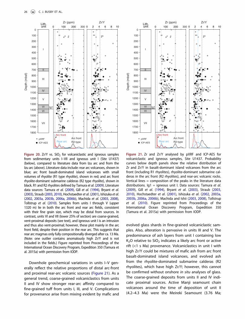
Downhole geochemical variations in units I–V gen-erally reflect the relative proportions of distal arc-frontand proximal rear-arc volcanic sources (Figure 21). As ageneral trend, coarse-grained volcaniclastics from unitsII and IV show stronger rear-arc affinity compared tofine-grained tuff from units I, III, and V. Complicationsfor provenance arise from mixing evident by mafic and
evolved glass shards in fine-grained volcaniclastic sam-ples. Also, alteration is pervasive in units III and V. Thepredominance of ash layers from unit I containing lowK2O relative to SiO2 indicates a likely arc front or activerift (<1 s Ma) provenance. Volcaniclastics in unit I withhigh Zr/Y could be mixtures of mafic ash from arc frontbasalt-dominated island volcanoes, and evolved ashfrom the rhyolite-dominated submarine calderas (R2rhyolites), which have high Zr/Y; however, this cannotbe confirmed without onshore in situ analyses of glass.The coarse-grained deposits from units II and IV indi-cate proximal sources. Active Manji seamount chainvolcanoes around the time of deposition of unit II(4.2–4.3 Ma) were the Meireki Seamount (3.76 Ma;
I
II
III
IV
VII
VI
V
Ig1
pXRF
ICP-AES
Arc front
Rear arcArc frontR2-type
0
100
200
300
400
500
600
700
800
900
1000
1100
1200
1300
1400
1500
1600
1700
1800
Dep
th (
mbs
f)Zr (ppm) Zr/YLith.
unit 3000 100 200 0 2 4 6 8 10
VI
Figure 20. Zr/Y vs. SiO2 for volcaniclastic and igneous samplesfrom sedimentary units I–VII and igneous unit I (Site U1437)(below), compared to literature data from Izu arc and from theIzu arc (above). Literature data include: rear arc volcanoes, shown inblue; arc front basalt-dominated island volcanoes with smallvolumes of rhyolite (R1 type rhyolite), shown in red; and arc frontrhyolite-dominant submarine calderas (R2 type rhyolite), shown inblack. R1 and R2 rhyolites defined by Tamura et al. (2009). Literaturedata sources: Tamura et al. (2009), Gill et al. (1994), Bryant et al.(2003), Straub (2003, 2010), Hochstaedter et al. (2001), Ishizuka et al.(2002, 2003a, 2003b, 2006a, 2006b), Machida et al. (2003, 2008),Tollstrup et al. (2010). Samples from units I through V (upper1320 m) lie in both the arc front and rear arc fields, consistentwith their fine grain size, which may be distal from sources. Incontrast, units VI and VII (lower 25% of section) are coarse-grained,vent-proximal deposits (see text), and igneous unit I is an intrusionand thus also vent-proximal; however, these plot mainly in the arcfront field, despite their position in the rear arc. This suggests thatrear arcmagmas only fully compositionally diverged after ca. 13Ma.(Note: one outlier contains anomalously high Zr/Y and is notincluded in the fields.) Figure reprinted from Proceedings of theInternational Ocean Discovery Program, Expedition 350 (Tamura etal. 2015a) with permission from IODP.
I
II
III
IV
VII
VI
V
Ig1
pXRF
ICP-AES
Arc front
Rear arcArc frontR2-type
0
100
200
300
400
500
600
700
800
900
1000
1100
1200
1300
1400
1500
1600
1700
1800
Dep
th (
mbs
f)
Zr (ppm) Zr/YLith.unit 3000 100 200 0 2 4 6 8 10
VI
Figure 21. Zr and Zr/Y analysed by pXRF and ICP-AES forvolcaniclastic and igneous samples, Site U1437. Probabilitycurves below depth panels show the relative distribution ofZr and Zr/Y in basalt-dominant island volcanoes from the arcfront (including R1 rhyolites), rhyolite-dominant submarine cal-deras in the arc front (R2 rhyolites), and rear-arc volcanic rocks.Vertical lines = composition of the peaks in the literature datadistributions. Ig1 = igneous unit I. Data sources: Tamura et al.(2009), Gill et al. (1994), Bryant et al. (2003), Straub (2003,2010), Hochstaedter et al. (2001), Ishizuka et al. (2002, 2003a,2003b, 2006a, 2006b), Machida and Ishii (2003, 2008), Tollstrupet al. (2010). Figure reprinted from Proceedings of theInternational Ocean Discovery Program, Expedition 350(Tamura et al. 2015a) with permission from IODP.
26 C. J. BUSBY ET AL.

Ishizuka et al. 1998) ~20 km to the north and the Daigo-Nishi-Aogashima Knoll (5.05 Ma; Ishizuka et al. 2003b)~40 km to the northeast of Site U1437 (Figure 7). Bothare rhyolite volcanoes with similar SiO2 contents (72–76 wt%), whereas Meireki Seamount volcanic rockshave higher K2O (~3 wt%) but lower Zr/Y (~2.8) com-pared to the Daigo-Nishi-Aogashima Knoll(K2O = ~ 1.5 wt%; Zr/Y = ~ 4.4) (Hochstaedter et al.2001). Although the limited data (five analyses in total)available for both seamounts preclude reliable geo-chemical matching with unit II volcaniclastics, they arepotential sources for lapilli in unit II considering theirgeographic locations, ages, and chemical composition.Similarly, single clast compositions of unit IV can betentatively matched to available data for ManjiSeamount volcanic rocks (Figure 7; ~6.5–6.9 Ma;Ishizuka et al. 2002). Two high-K2O volcaniclasticsresemble the high-K Manji Seamount rocks with potas-sic alteration, whereas most volcaniclastics from unit IVfollow the trend for altered Manji Seamount rocks(Ishizuka et al. 2002), including depletions in CaO withincreasing SiO2 (see Figure F44 of Tamura et al. 2015a).Unit V is primarily tuffaceous mudstone, and given thepervasive alteration throughout this unit, it is difficult toprovide an accurate provenance for its volcaniclasticintervals.
The geochemistry of samples from units VI and VIIand igneous unit I does not fall neatly into the rear-arcfield, but instead spans both fields (Figure 20), eventhough a rear-arc source is demanded by the vent-proximal nature of the deposits (described earlier).One of the goals of Expedition 350 (Tamura et al.2013) was to determine the timing of development ofgeochemical asymmetry between the arc front and reararc. This is important because dredge samples thatwere already in hand from Neogene volcanoes of therear arc were more ‘continental’ in chemical composi-tion than dredge and drill core samples from the arcfront, therefore making the rear arc more suitable as apossible building block for continental crust. We pre-sented two models for the development of arc asym-metry: ‘from the beginning’ and ‘from the middle’(Tamura et al. 2013). The ‘from the beginning’ hypoth-esis stipulated that arc asymmetry was established atEocene arc inception and persisted through theNeogene. The ‘from the middle’ hypothesis stipulatedthat the asymmetry developed during an arc hiatusassociated with opening of the Shikoku backarc basinat 27–17 Ma. On the basis of seismic stratigraphy, weexpected to reach Oligocene (>23 Ma) strata at1250 mbsf, to determine which hypothesis was correct,but instead those strata are 9 Ma (late Miocene; lowerpart of unit V), so the chemistry of the Palaeogene rear
arc remains unknown. However, the compositional het-erogeneity of units VI and VII suggests that arc asym-metry did not develop until after ~13 Ma (middleMiocene), which is during the Neogene, that is, neither‘from the beginning’ nor ‘from the middle’.
Depositional model
The biggest surprise of the expedition was the predo-minance of tuffaceous mud and the fine grain size ofthe volcaniclastics at Site U1437. We expected to drillinto a volcaniclastic apron (see Scientific Prospectus;Tamura et al. 2013), with abundant large lapilli- toblock-sized volcanic clasts that could be geochemicallyanalysed individually on the ship. This is not what weencountered, but before presenting the depositionalmodel, it is necessary to define the term ‘volcaniclasticapron’ in order to show how the depositional model forSite U1437 differs from models for volcaniclastic aprons.
Although some may use the term ‘volcaniclasticapron’ to loosely refer to any accumulation of sedimentaround a volcano or chain of volcanoes, the term hasbeen used in a much more rigorous sense by sedimen-tologists over the past 40 years (Karig and Moore1975b; Sample and Karig 1982; Carey and Sigurdsson1984; Farquharson et al. 1984; Fisher 1984; Busby-Spera1985, 1988; Cas and Wright 1987; Smith 1987; Whiteand Busby-Spera 1987; Houghton and Landis 1989;Palmer and Walton 1990; Fisher and Smith 1991;Fisher and Schmincke 1994; Smith and Landis 1995;Orton 1996; Wright 1996; Carey 2000; Mitchell 2000;Gamberi 2001; Karátson and Németh 2001; Allen et al.2006; Casalbore et al. 2010; Carey and Schneider 2011).In these papers, a volcaniclastic apron is defined as athick accumulation of coarse volcanic debris thatfringes a volcano or a chain of volcanoes and buildsoutward from them; volcaniclastic aprons are typicallyfan shaped or are composed of coalescing fans thatform a wedge. They are steep in their proximal reaches,with abundant large lithic blocks and slumps, passingsmoothly into medial to distal reaches that have gentlerslopes, formed of debris flow and coarse-grained pyr-oclastic density current deposits. For example, the ‘vol-canic apron’ of Gran Canaria is a volcaniclastic apron(Funck et al. 1996), consisting of volcano-flank seismi-cally chaotic pillow breccia and hylaoclastite and poorlystratified debris flow deposits, which pass basinwardinto crudely stratified slump, debris flow, and turbiditycurrent deposits. The submarine flanks of AnahatanVolcano and Northeast Anahatan Volcano (MarianaArc) are largely mantled with volcaniclastic aprons,which extend 5–20 km from the island of Anahatan;these have slopes decreasing from 15–25° to 5° with
INTERNATIONAL GEOLOGY REVIEW 27

distance, and their outer edge is marked by a distinctbreak in slope, with abyssal sediment beyond(Chadwick et al. 2005). Volcaniclastic aprons form inboth nonmarine and marine environments, and theycommonly prograde into basins with time, producingan overall upward-coarsening sequence.
The depositional model for Site U1437 must takeaccount of the fact that it is an entirely deep-waterdeposit, and using the criteria above, it clearly doesnot represent a volcaniclastic apron. The depositionalmodel may instead be based on analogies with theother major type of deep-water depositional system,the submarine fans and aprons of siliciclastic deep-water systems. Submarine fans and aprons are relativelycoarse grained constructional features, whereas thebasin plain beyond is flat and fine grained with laterallycontinuous deposits (Reading and Richards 1994; Stowet al. 1996; Richards 2009). The upper 75% of the sec-tion drilled at Site U1437 is analogous to the basinplain; it is a fine-grained, well-stratified sequence withlaterally continuous layers. For this reason, we refer to itas a deep-water basinal succession, not a volcaniclasticapron.
The lower 25% of the section, in contrast, consistslargely of blocky hyaloclastic deposits (unit VII, 347 m)that cooled in situ with very limited remobilization andthus represent near-vent deposits. It also includes lesserpolymict lapilli tuffs (unit VI, 140 m) sourced fromnearby volcanoes but also with rhyolite blocks locallyderived from igneous unit I (within unit VI). Therefore,the lower 25% of the section is dominated by localizedvent-related deposits within the deep-water basinalsuccession. As discussed earlier, the geochemistry ofthe lower 25% also differs from the upper 75% of thesection.
Conclusion: surprises and questions to beaddressed in shore-based investigations
Four surprises resulted from drilling at U1437 that ledto questions for on-going (shore-based) investigation,to be summarized in future papers.
The first surprise is that the section is much moremud-rich than expected for an arc-proximal sedimen-tary succession. The section as a whole is 60% tuffac-eous mudstone, with 89% in the uppermost 433 m, andwith high sedimentation rates of 100–260 m/millionyear for the upper 1300 m. What was the source of allthat mud, and how was it deposited?
The second surprise is that the grain size of thevolcaniclastics is much smaller than expected for anarc-proximal sedimentary succession, composed ofhalf ash/tuff and half fine-grained lapilli tuff. No
volcanic blocks are present in the upper 75% of thesection. Yet Site U1437 lies downslope, within kilo-metres to tens of kilometre, of seamounts dated at6.86–6.53 (Manji), 3.76 Ma (Meoreki), and 5.05 and0.55 Ma (Daigo-Nishi-Aogashima Knoll) from dredgedsamples, as shown in Figure 7. This may indicate thatmost <7 Ma eruptions from the seamounts were small-volume effusions that did not produce much volcani-clastic material. Alternatively, the dredged samplesrepresent late-stage, small volume eruptions that man-tle the surfaces on the seamounts, and they were lar-gely built before ~9 Ma.
The third surprise is that the section is much youngerthan predicted from seismic stratigraphy. For example,Oligocene (>23 Ma) strata were predicted at 1250 mbsf,but instead those strata are 9 Ma (Miocene).
Fourth, it was predicted that compositional diver-gence between arc-front and rear-arc magmas devel-oped during a volcanic hiatus associated with openingof the backarc basin at 27–17 Ma, if it did not alreadyexist from the time of arc inception in the Eocene(~45 Ma); however, preliminary data presented heresuggest that this divergence only fully developed after~13–14 Ma (middle Miocene). The cause is not known.
Acknowledgements
We thank all of the personnel aboard the R/V Joides Resolutionduring Expedition 350 for their skill and dedication. The edi-torial staff at the IODP JOIDES Resolution Science Operator inTAMU are thanked for help with publication of the Expedition350 Proceedings volume, which is summarized herein. Wealso thank Bob Stern for his participation as a shore-basedscientist, and for encouraging us to write this article. Helpfulreviews provided by two anonymous reviewers are gratefullyacknowledged.
Disclosure statement
No potential conflict of interest was reported by the authors.
References
Allen, S.R., Hayward, B.W., and Mathews, E., 2006, A faciesmodel for a submarine volcaniclastic apron: The MioceneManukau Subgroup, New Zealand: Geological Society ofAmerica Bulletin, v. 119, no. 5–6, p. 725–742. doi:10.1130/B26066.1
Andrews, G.D.M., Schmitt, A.K., Busby, C.J., and Brown, S.R.,2015, Geochronology and geochemistry of zircons fromIODP Site U1437: in the rear arc of the Izu-Bonin volcanicchain: American Geophysical Union Fall Meeting, AbstractDl13A-2627.
Arculus, R., Ishizuka, O., and Bogus, K.A., 2013, Izu-Bonin-Mariana arc origins: Continental crust formation at intrao-ceanic arc: Foundations, inceptions, and early evolution:
28 C. J. BUSBY ET AL.

International Ocean Discovery Program ScientificProspectus, p. 351. doi:10.2204/iodp.sp.351.2013
Arculus, R., Ishizuka, O., and Bogus, M.H. and the Expedition351 Scientists, 2015, Proceedings of the InternaitonalOcean Discovery Program, Volume 351 publications.iodp.org. doi:10.14379/iodp.proc.351.101.2015
Bandy, W.L., and Hilde, T.W.C., 1983, Structural features of theBonin arc: Implications for its tectonic history:Tectonophysics, v. 99, no. 2–4, p. 331–353. doi:10.1016/0040-1951(83)90111-7
Bloomer, S.H., Taylor, B., MacLeod, C.J., Stern, R.J., Fryer, P.,Hawkins, J.W., and Johnson, L., 1995, Early arc volcanismand the ophiolite problem: A perspective from drilling inthe western Pacific, in Taylor, B., and Natland, J., eds., Activemargins and marginal basins of the western Pacific:Geophysical Monograph, v. 88, p. 1-30. doi:10.1029/GM088p0001
Bryant, C.J., Arculus, R.J., and Eggins, S.M., 2003, The geochem-ical evolution of the Izu-Bonin arc system: A perspectivefrom tephras recovered by deep-sea drilling: Geochemistry,Geophysics, Geosystems, v. 4, no. 11, p. 1094. doi:10.1029/2002GC000427
Busby-Spera, C.J., 1985, A sand-rich submarine fan in thelower Mesozoic Mineral King caldera complex, SierraNevada, California: Journal of Sedimentary Research, v. 55,no. 3, p. 376–391. doi:10.1306/212F86D9-2B24-11D7-8648000102C1865D
Busby-Spera, C.J., 1988, Evolution of a middle Jurassic back-arc basin, Cedros Island, Baja California: Evidence from amarine volcaniclastic apron: Geological Society of AmericaBulletin, v. 100, no. 2, p. 218–233. doi:10.1130/0016-7606(1988)100<0218:EOAMJB>2.3.CO;2
Busby-Spera, C.J., and White, J.D.L., 1987, Variation in peperitetextures associated with differing host-sediment properties:Bulletin of Volcanology, v. 49, no. 6, p. 765–776.doi:10.1007/BF01079827
Carey, S., 1997, Influence of convective sedimentation on theformation of widespread tephra fall layers in the deep sea:Geology, v. 25, no. 9, p. 839–842. doi:10.1130/0091-7613(1997)025<0839:IOCSOT>2.3.CO;2
Carey, S., 2000, Volcaniclastic sedimentation around islandarcs, in Sigurdsson, H., Houghton, B.F., McNutt, S.R.,Rymer, H., and Stix, J., eds., Encyclopedia of volcanoes,San Diego: Academic Press, p. 627–642.
Carey, S., and Sigurdsson, H., 1984, A model of volcanogenicsedimentation in marginal basins, in Kokelaar, B.P., andHowells, M.F., eds., Marginal basin geology: Volcanic andassociated sedimentary and tectonic processes in modernand ancient marginal basins: Geological Society SpecialPublication v. 16, p. 37-58. doi:10.1144/GSL.SP.1984.016.01.04
Carey, S.N., and Schneider, J.-L., 2011, Volcaniclastic processesand deposits in the deep sea, in Hüneke, H., and Mulder, T.,eds., Developments in sedimentology, Volume 63: Deep-SeaSediments, Oxford: Elsevier, p. 457–515. doi:10.1016/B978-0-444-53000-4.00007-X
Cas, R.A.F., and Wright, J.V., 1987, Volcanic successions, mod-ern and ancient: A geological approach to processes, pro-ducts and successions: London, Allen and Unwin.
Casalbore, D., Romagnoli, C., Chiocci, F., and Frezza, V., 2010,Morpho-sedimentary characteristics of the volcaniclastic
apron around Stromboli volcano (Italy): Marine Geology, v.269, no. 3–4, p. 132–148. doi:10.1016/j.margeo.2010.01.004
Chadwick, W.W., Embley, R.W., Johnsons, P.D., Merle, S.G.,Ristau, S., and Bobbitt, A., 2005, The submarine flank ofAnatahan volcano: Commonwealth of the NorthernMariana Islands: Journal of Volcanology and GeothermalResearch, v. 146, p. 8–25.
Cosca, M.A., Arculus, R.J., Pearce, J.A., and Mitchell, J.G., 1998,40Ar/39Ar and K-Ar geochronological age constraints forthe inception and early evolution of the Izu-Bonin-Marianaarc system: The Island Arc, v. 7, no. 3, p. 579–595.doi:10.1111/j.1440-1738.1998.00211.x
Dickinson, W.R., and Hatherton, T., 1967, Andesitic volcanismand seismicity around the Pacific: Science, v. 157, no. 3790,p. 801–803. doi:10.1126/science.157.3790.801
Farquharson, G.W., Hamer, R.D., and Ineson, J.R., 1984,Proximal volcaniclastic sedimentation in a Cretaceousback-arc apron, northern Antarctic Peninsula, in Kokelaar,B.P., and Howells, M.F., eds., Marginal basin geology:Volcanic and associated sedimentary and tectonic pro-cesses in modern and ancient marginal basins: GeologicalSociety Special Publication v. 16, p. 5-27. doi:10.1144/GSL.SP.1984.016.01.17
Fisher, R.V., 1984, Submarine volcaniclastic rocks, in Kokelaar,B.P., and Howells, M.F., eds., Marginal basin geology:Volcanic and associated sedimentary processes in modernand ancient basins, vol. 16. Springer-Verlag; p. 5–27.doi:10.1144/GSL.SP.1984.016.01.02
Fisher, R.V., and Schmincke, H.-U., 1984, Pyroclastic rocks:Berlin, Springer-Verlag. doi:10.1007/978-3-642-74864-6
Fisher, R.V., and Schmincke, H.-U., 1994, Volcaniclastic sedi-ment transport and deposition, in Pye, K., eds., Sedimenttransport and depositional processes, Oxford, UK: BlackwellScientific Publishing, p. 351–388.
Fisher, R.V., and Smith, G.A., 1991, Volcanism, tectonics andsedimentation, in Fisher, R.V., and Smith, G.A., eds.,Sedimentation in volcanic settings, vol. 45. SpecialPublication-SEPM (Society for Sedimentary Geology; p. 1–5. doi:10.2110/pec.91.45.0001
Funck, T., Dickmann, T., Rihm, R., Krastel, S., Lykke-Andersen,H., and Schmincke, H.-U., 1996, Reflection seismic investiga-tions in the volcaniclastic apron of Gran Canaria and impli-cations for its volcanic evolution: Geophysical JournalInternational, v. 125, no. 2, p. 519–536. doi:10.1111/j.1365-246X.1996.tb00015.x
Gamberi, F., 2001, Volcanic facies associations in a modernvolcaniclastic apron (Lipari and Vulcano offshore, AeolianIsland arc): Bulletin of Volcanology, v. 63, no. 4, p. 264–273.doi:10.1007/s004450100143
Gill, J.B., 1981, Minerals and rocks, Volume 16: OrogenicAndesites and Plate Tectonics: Berlin, Springer-Verlag.doi:10.1007/978-3-642-68012-0
Gill, J.B., Hiscott, R.N., and Vidal, P., 1994, Turbidite geochem-istry and evolution of the Izu-Bonin arc and continents:Lithos, v. 33, no. 1–3, p. 135–168. doi:10.1016/0024-4937(94)90058-2
Hochstaedter, A., Gill, J., Peters, R., Broughton, P., Holden, P.,and Taylor, B., 2001, Across-arc geochemical trends in theIzu-Bonin arc: Contributions from the subducting slab:Geochemistry, Geophysics, Geosystems, v. 2, no. 7, p.1019. doi:10.1029/2000GC000105
INTERNATIONAL GEOLOGY REVIEW 29

Hochstaedter, A.G., Gill, J.B., Kusakabe, M., Newman, S.,Pringle, M., Taylor, B., and Fryer, P., 1990a, Volcanism inthe Sumisu Rift, I. Major element, volatile, and stable iso-tope geochemistry: Earth and Planetary Science Letters, v.100, no. 1–3, p. 179–194. doi:10.1016/0012-821X(90)90184-Y
Hochstaedter, A.G., Gill, J.B., and Morris, J.D., 1990b, Volcanismin the Sumisu Rift, II. Subduction and non-subductionrelated components: Earth and Planetary Science Letters,v. 100, no. 1–3, p. 195–209. doi:10.1016/0012-821X(90)90185-Z
Hochstaedter, A.G., Gill, J.B., Taylor, B., Ishizuka, O., Yuasa, M.,and Monta, S., 2000, Across-arc geochemical trends in theIzu-Bonin arc: Constraints on source composition and man-tle melting: Journal of Geophysical Research: Solid Earth, v.105, no. B1, p. 495–512. doi:10.1029/1999JB900125
Houghton, B.F., and Landis, C.A., 1989, Sedimentation andvolcanism in a Permian arc-related basin, southern NewZealand: Bulletin of Volcanology, v. 51, no. 6, p. 433–450.doi:10.1007/BF01078810
Ishizuka, O., Kimura, J.-I., Li, Y.B., Stern, R.J., Reagan, M.K.,Taylor, R.N., Ohara, Y., Bloomer, S.H., Ishii, T., Hargrove, U.S., III, and Haraguchi, S., 2006a, Early stages in the evolutionof Izu-Bonin arc volcanism: New age, chemical, and isotopicconstraints: Earth and Planetary Science Letters, v. 250, no.1–2, p. 385–401. doi:10.1016/j.epsl.2006.08.007
Ishizuka, O., Taylor, R.N., Milton, J.A., and Nesbitt, R.W., 2003a,Fluid-mantle interaction in an intraoceanic arc: Constraintsfrom high-precision Pb isotopes: Earth and PlanetaryScience Letters, v. 211, no. 3–4, p. 221–236. doi:10.1016/S0012-821X(03)00201-2
Ishizuka, O., Taylor, R.N., Milton, J.A., Nesbitt, R.W., Yuasa, M.,and Sakamoto, I., 2006b, Variation in the mantle sources ofthe northern Izu arc with time and space—Constraints fromhigh-precision Pb isotopes: Journal of Volcanology andGeothermal Research, v. 156, no. 3–4, p. 266–290.doi:10.1016/j.jvolgeores.2006.03.005
Ishizuka, O., Taylor, R.N., Yuasa, M., and Ohara, Y., 2011,Making and breaking an island arc: A new perspectivefrom the Oligocene Kyushu-Palau arc, Philippine Sea:Geochemistry, Geophysics, Geosystems, v. 12, no. 5, p.Q05005. doi:10.1029/2010GC003440
Ishizuka, O., Uto, K., and Yuasa, M., 2003b, Volcanic history ofthe back-arc region of the Izu-Bonin (Ogasawara) arc, inLarter, R.D., and Leat, P.T., eds., Tectonic and magmaticprocesses, Geological Society Special Publication v. 291, p.187-205. doi:10.1144/GSL.SP.2003.219.01.09
Ishizuka, O., Uto, K., Yuasa, M., and Hochstaedter, A.G., 1998, K-Ar ages from seamount chains in the back-arc region of theIzu-Ogasawara arc: The Island Arc, v. 7, no. 3, p. 408–421.doi:10.1111/j.1440-1738.1998.00199.x
Ishizuka, O., Yuasa, M., and Uto, K., 2002, Evidence of porphyrycopper-type hydrothermal activity from a submerged rem-nant back-arc volcano of the Izu-Bonin arc: Implications forthe volcanotectonic history of back-arc seamounts: Earthand Planetary Science Letters, v. 198, no. 3–4, p. 381–399.doi:10.1016/S0012-821X(02)00515-0
Karátson, D., and Németh, K., 2001, Lithofacies associations ofan emerging volcaniclastic apron in a Miocene volcaniccomplex: An example from the Börzsöny Mountains,Hungary: International Journal of Earth Sciences, v. 90, no.4, p. 776–794. doi:10.1007/s005310100193
Karig, D.E., and Moore, G.F., 1975a, Tectonic complexities inthe Bonin arc system: Tectonophysics, v. 27, no. 2, p. 97–118. doi:10.1016/0040-1951(75)90101-8
Karig, D.E., and Moore, G.F., 1975b, Tectonically controlledsedimentation in marginal basins: Earth and PlanetaryScience Letters, v. 26, no. 2, p. 233–238. doi:10.1016/0012-821X(75)90090-4
Kodaira, S., Sato, T., Takahashi, N., Ito, A., Tamura, Y., Tatsumi,Y., and Kaneda, Y., 2007a, Seismological evidence for vari-able growth of crust along the Izu intraoceanic arc: Journalof Geophysical Research: Solid Earth, v. 112, no. B5, p.B05104. doi:10.1029/2006JB004593
Kodaira, S., Sato, T., Takahashi, N., Miura, S., Tamura, Y.,Tatsumi, Y., and Kaneda, Y., 2007b, New seismological con-straints on growth of continental crust in the Izu-Boninintra-oceanic arc: Geology, v. 35, no. 11, p. 1031–1034.doi:10.1130/G23901A.1
Kodaira, S., Sato, T., Takahashi, N., Yamashita, M., No, T., andKaneda, Y., 2008, Seismic imaging of a possible paleoarc inthe Izu-Bonin intraoceanic arc and its implications for arcevolution processes: Geochemistry, Geophysics,Geosystems, v. 9, no. 10, p. Q10X01. doi:10.1029/2008GC002073
Konrad, K., Schmitt, A.K., Andrews, G.D., Horle, K., Brown, S.R.,Koppers, A.A.P., Busby, C., and Tamura, Y., 2016, 40Ar/39Ardating and zircon chronochemistry for the Izu-Bonin reararc, in IODP site U1437: American Geophysical Union FallMeeting, Abstract V13C-2853.
Kuno, H., 1959, Origin of Cenozoic petrographic provinces ofJapan and surrounding areas: Bulletin of Volcanology, v. 20,no. 1, p. 37–76. doi:10.1007/BF02596571
Machida, S., and Ishii, T., 2003, Backarc volcanism along the enechelon seamounts: The Enpo Seamount chain in thenorthern Izu-Ogasawara arc: Geochemistry, Geophysics,Geosystems, v. 4, no. 8, p. 9006. doi:10.1029/2003GC000554
Machida, S., Ishii, T., Kimura, J.-I., Awaji, S., and Kato, Y., 2008,Petrology and geochemistry of cross-chains in the Izu-Bonin back arc: Three mantle components with contribu-tions of hydrous liquids from a deeply subducted slab:Geochemistry, Geophysics, Geosystems, v. 9, no. 5, p.Q05002. doi:10.1029/2007GC001641
Manville, V., and Wilson, C.J.N., 2004, Vertical density currents:A review of their potential role in the deposition and inter-pretation of deep-sea ash layers: Journal of the GeologicalSociety, v. 161, no. 6, p. 947–958. doi:10.1144/0016-764903-067
McPhie, J., Doyle, M., and Allen, R., 1993, Volcanic textures: Aguide to the interpretation of textures in volcanic rocks:Hobart, Tasmanian Government Printing Office.
Mitchell, S.F., 2000, Facies analysis of a Cretaceous–Paleocenevolcaniclastic braid-delta, in Presented at the GeologicalSociety of Trinidad and Tobago 2000 SPE Conference andExhibition, Port of Spain, Trinidad, 10–13 July 2000 (PaperSS03). http://archives.datapages.com/data/gstt/SS03F.PDF
Orton, G.J., 1996, Volcanic environments, in Reading, H.G.,eds., Sedimentary environments: Processes, facies and stra-tigraphy, Oxford, UK: Blackwell Science Publishing, p. 485–573.
Palmer, B.A., and Walton, A.W., 1990, Accumulation of volca-niclastic aprons in the Mount Dutton Formation(Oligocene–Miocene), Marysvale volcanic field, Utah:Geological Society of America Bulletin, v. 102, no. 6, p.
30 C. J. BUSBY ET AL.

734–748. doi:10.1130/0016-7606(1990)102<0734:AOVAIT>2.3.CO;2
Pearce, J.A., Reagan, M.K., Stern, R.J., and Petronotis, K., 2013,Izu-Bonin-Mariana fore-arc: Testing subduction initiationand ophiolite models by drilling the outer Izu-Bonin-Mariana fore arcfore-arc: International Ocean DrillingProgram Scientific Prospectus, v. 352. doi:10.14379/iodp.sp.352.2013
Plank, T., 2014, The chemical composition of subducting sedi-ments, in Rudnick, R.L., ed., Treatise on geochemistry (sec-ond edition), Volume 4: The Crust. Holland, H.D., andTurekian, K.K. (Series eds.), Oxford: Elsevier, p. 607–629.doi:10.1016/B978-0-08-095975-7.00319-3
Reading, H.G., and Richards, M., 1994, Turbidite systems indeep-water basin margins classified by grain size and fee-der system: AAPG Bulletin, v. 78, no. 5, p. 792–822. http://aapgbull.geoscienceworld.org/cgi/content/abstract/78/5/792
Reagan, M.K., Ishizuka, O., Stern, R.J., Kelley, K.A., Ohara, Y.,Blichert-Toft, J., Bloomer, S.H., Cash, J., Fryer, P., Hanan, B.B.,Hickey-Vargas, R., Ishii, T., Kimura, J.-I., Peate, D.W., Rowe, M.C., and Woods, M., 2010, Fore-arc basalts and subductioninitiation in the Izu-Bonin-Mariana system: Geochemistry,Geophysics, Geosystems, v. 11, no. 3, p. Q03X12.doi:10.1029/2009GC002871
Reagan, M.K., Pearce, J.A., and Petronotis, K., and ExpeditionScientists, 2015, Izu-Bonin-Mariana Fore Arc. Proceedings ofthe International Ocean Discovery Program: InternationalOcean Discovery Program, v. 352. doi:10.14379/iodp.proc.352.2015
Richards, M.T., 2009, Deep-marine clastic systems, in Emery, D.,and Myers, K., eds., Sequence stratigraphy, London:Blackwell Science Publishing, p. 178–210. doi:10.1002/9781444313710.ch9
Sample, J.C., and Karig, D.E., 1982, A volcanic production ratefor the Mariana island arc: Journal of Volcanology andGeothermal Research, v. 13, no. 1–2, p. 73–82.doi:10.1016/0377-0273(82)90020-8
Smith, G.A., 1987, Sedimentology of volcanism-induced aggra-dation in fluvial basins: Examples from the PacificNorthwest, U.S.A., in Ethridge, F.G., Flores, R.M., andHarvey, M.D., eds., Recent developments in fluvial sedimen-tology, Special Publication – SEPM (Society for SedimentaryGeology) v. 39, p. 217-228. doi:10.2110/pec.87.39.0217
Smith, G.A., and Landis, C., 1995, Intra-arc basins, in Busby, C.J., and Ingersoll, R.V., eds., Tectonics of sedimentary basins,Oxford: Blackwell Science Publishing, p. 263–298.
Stern, R.J., Fouch, M.J., and Klemperer, S., 2003, An overview ofthe Izu-Bonin-Mariana subduction factory, in Eiler, J., eds.,Inside the subduction factory: Geophysical Monograph v.138, p. 175-122. doi:10.1029/138GM10
Stow, D.A.V., Reading, H.G., and Collinson, J.D., 1996, Deepseas, in Reading, H.G., eds., Sedimentary environments:Processes, facies and stratigraphy, Oxford, UK: BlackwellScience Publishing, p. 395–453.
Straub, S.M., 2003, The evolution of the Izu Bonin - Marianavolcanic arcs (NW Pacific) in terms of major element chem-istry: Geochemistry, Geophysics, Geosystems, v. 4, no. 2, p.1018. doi:10.1029/2002GC000357
Straub, S.M., Goldstein, S.L., Class, C., Schmidt, A., and Gomez-Tuena, A., 2010, Slab and mantle controls on the Sr–Nd–Pb–Hf isotope evolution of the post 42 Ma Izu–Bonin
volcanic arc: Journal of Petrology, v. 51, no. 5, p. 993–1026. doi:10.1093/petrology/egq009
Suyehiro, K., Takahashi, N., Ariie, Y., Yokoi, Y., Hino, R.,Shinohara, M., Kanazawa, T., Hirata, N., Tokuyama, H., andTaira, A., 1996, Continental crust, crustal underplating, andlow-Q upper mantle beneath an oceanic island arc: Science,v. 272, no. 5260, p. 390–392. doi:10.1126/science.272.5260.390
Tamura, Y., Busby, C., and Blum, P., 2013, Izu-Bonin-MarianaRear Arc: The missing half of the subduction factory:International Ocean Discovery Program ScientificProspectus, p. 350. doi:10.2204/iodp.sp.350.2013
Tamura, Y., Busby, C.J., Blum, P., Guèrin, G., Andrews, G.D.M.,Barker, A.K., Berger, J.L.R., Bongiolo, E.M., Bordiga, M.,DeBari, S.M., Gill, J.B., Hamelin, C., Jia, J., John, E.H., Jonas,A.-S., Jutzeler, M., Kars, M.A.C., Kita, Z.A., Konrad, K.,Mahoney, S.H., Martini, M., Miyazaki, T., Musgrave, R.J.,Nascimento, D.B., Nichols, A.R.L., Ribeiro, J.M., Sato, T.,Schindlbeck, J.C., Schmitt, A.K., Straub, S.M., Vautravers, M.J., and Yang, Y., 2015a, Expedition 350 summary, in Tamura,Y., Busby, C.J., and Blum, P., and the Expedition 350Scientists, eds., Proceedings of the International OceanDiscovery Program, Expedition 350: Izu-Bonin-MarianaRear Arc, College Station, TX: International OceanDiscovery Program. doi:10.14379/iodp.proc.350.101.2015
Tamura, Y., Busby, C.J., Blum, P., Guèrin, G., Andrews, G.D.M.,Barker, A.K., Berger, J.L.R., Bongiolo, E.M., Bordiga, M.,DeBari, S.M., Gill, J.B., Hamelin, C., Jia, J., John, E.H., Jonas,A.-S., Jutzeler, M., Kars, M.A.C., Kita, Z.A., Konrad, K.,Mahoney, S.H., Martini, M., Miyazaki, T., Musgrave, R.J.,Nascimento, D.B., Nichols, A.R.L., Ribeiro, J.M., Sato, T.,Schindlbeck, J.C., Schmitt, A.K., Straub, S.M., Vautravers, M.J., and Yang, Y., 2015b, Expedition 350 methods, in Tamura,Y., Busby, C.J., and Blum, P., and the Expedition 350Scientists, eds., Proceedings of the International OceanDiscovery Program, Expedition 350: Izu-Bonin-MarianaRear Arc, College Station, TX: International OceanDiscovery Program. doi:10.14379/iodp.proc.350.102.2015
Tamura, Y., Busby, C.J., Blum, P., Guèrin, G., Andrews, G.D.M.,Barker, A.K., Berger, J.L.R., Bongiolo, E.M., Bordiga, M.,DeBari, S.M., Gill, J.B., Hamelin, C., Jia, J., John, E.H., Jonas,A.-S., Jutzeler, M., Kars, M.A.C., Kita, Z.A., Konrad, K.,Mahoney, S.H., Martini, M., Miyazaki, T., Musgrave, R.J.,Nascimento, D.B., Nichols, A.R.L., Ribeiro, J.M., Sato, T.,Schindlbeck, J.C., Schmitt, A.K., Straub, S.M., Vautravers, M.J., and Yang, Y., 2015c, Site U1436, in Tamura, Y., Busby, C.J.,and Blum, P., and the Expedition 350 Scientists, eds.,Proceedings of the International Ocean DiscoveryProgram, Expedition 350: Izu-Bonin-Mariana Rear Arc,College Station, TX: International Ocean DiscoveryProgram. doi:10.14379/iodp.proc.350.103.2015
Tamura, Y., Busby, C.J., Blum, P., Guèrin, G., Andrews, G.D.M.,Barker, A.K., Berger, J.L.R., Bongiolo, E.M., Bordiga, M.,DeBari, S.M., Gill, J.B., Hamelin, C., Jia, J., John, E.H., Jonas,A.-S., Jutzeler, M., Kars, M.A.C., Kita, Z.A., Konrad, K.,Mahoney, S.H., Martini, M., Miyazaki, T., Musgrave, R.J.,Nascimento, D.B., Nichols, A.R.L., Ribeiro, J.M., Sato, T.,Schindlbeck, J.C., Schmitt, A.K., Straub, S.M., Vautravers, M.J., and Yang, Y., 2015d, Site U1437, in Tamura, Y., Busby, C.J., and Blum, P., and the Expedition 350 Scientists, eds.,Proceedings of the International Ocean DiscoveryProgram, Expedition 350: Izu-Bonin-Mariana Rear Arc,
INTERNATIONAL GEOLOGY REVIEW 31
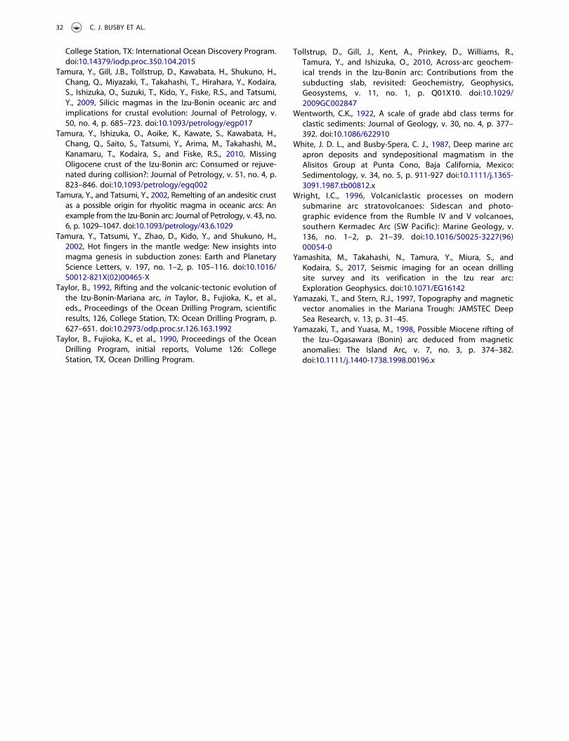
College Station, TX: International Ocean Discovery Program.doi:10.14379/iodp.proc.350.104.2015
Tamura, Y., Gill, J.B., Tollstrup, D., Kawabata, H., Shukuno, H.,Chang, Q., Miyazaki, T., Takahashi, T., Hirahara, Y., Kodaira,S., Ishizuka, O., Suzuki, T., Kido, Y., Fiske, R.S., and Tatsumi,Y., 2009, Silicic magmas in the Izu-Bonin oceanic arc andimplications for crustal evolution: Journal of Petrology, v.50, no. 4, p. 685–723. doi:10.1093/petrology/egp017
Tamura, Y., Ishizuka, O., Aoike, K., Kawate, S., Kawabata, H.,Chang, Q., Saito, S., Tatsumi, Y., Arima, M., Takahashi, M.,Kanamaru, T., Kodaira, S., and Fiske, R.S., 2010, MissingOligocene crust of the Izu-Bonin arc: Consumed or rejuve-nated during collision?: Journal of Petrology, v. 51, no. 4, p.823–846. doi:10.1093/petrology/egq002
Tamura, Y., and Tatsumi, Y., 2002, Remelting of an andesitic crustas a possible origin for rhyolitic magma in oceanic arcs: Anexample from the Izu-Bonin arc: Journal of Petrology, v. 43, no.6, p. 1029–1047. doi:10.1093/petrology/43.6.1029
Tamura, Y., Tatsumi, Y., Zhao, D., Kido, Y., and Shukuno, H.,2002, Hot fingers in the mantle wedge: New insights intomagma genesis in subduction zones: Earth and PlanetaryScience Letters, v. 197, no. 1–2, p. 105–116. doi:10.1016/S0012-821X(02)00465-X
Taylor, B., 1992, Rifting and the volcanic-tectonic evolution ofthe Izu-Bonin-Mariana arc, in Taylor, B., Fujioka, K., et al.,eds., Proceedings of the Ocean Drilling Program, scientificresults, 126, College Station, TX: Ocean Drilling Program, p.627–651. doi:10.2973/odp.proc.sr.126.163.1992
Taylor, B., Fujioka, K., et al., 1990, Proceedings of the OceanDrilling Program, initial reports, Volume 126: CollegeStation, TX, Ocean Drilling Program.
Tollstrup, D., Gill, J., Kent, A., Prinkey, D., Williams, R.,Tamura, Y., and Ishizuka, O., 2010, Across-arc geochem-ical trends in the Izu-Bonin arc: Contributions from thesubducting slab, revisited: Geochemistry, Geophysics,Geosystems, v. 11, no. 1, p. Q01X10. doi:10.1029/2009GC002847
Wentworth, C.K., 1922, A scale of grade abd class terms forclastic sediments: Journal of Geology, v. 30, no. 4, p. 377–392. doi:10.1086/622910
White, J. D. L., and Busby-Spera, C. J., 1987, Deep marine arcapron deposits and syndepositional magmatism in theAlisitos Group at Punta Cono, Baja California, Mexico:Sedimentology, v. 34, no. 5, p. 911-927 doi:10.1111/j.1365-3091.1987.tb00812.x
Wright, I.C., 1996, Volcaniclastic processes on modernsubmarine arc stratovolcanoes: Sidescan and photo-graphic evidence from the Rumble IV and V volcanoes,southern Kermadec Arc (SW Pacific): Marine Geology, v.136, no. 1–2, p. 21–39. doi:10.1016/S0025-3227(96)00054-0
Yamashita, M., Takahashi, N., Tamura, Y., Miura, S., andKodaira, S., 2017, Seismic imaging for an ocean drillingsite survey and its verification in the Izu rear arc:Exploration Geophysics. doi:10.1071/EG16142
Yamazaki, T., and Stern, R.J., 1997, Topography and magneticvector anomalies in the Mariana Trough: JAMSTEC DeepSea Research, v. 13, p. 31–45.
Yamazaki, T., and Yuasa, M., 1998, Possible Miocene rifting ofthe Izu–Ogasawara (Bonin) arc deduced from magneticanomalies: The Island Arc, v. 7, no. 3, p. 374–382.doi:10.1111/j.1440-1738.1998.00196.x
32 C. J. BUSBY ET AL.
Related Documents