HAL Id: hal-00765455 https://hal-mines-paristech.archives-ouvertes.fr/hal-00765455 Submitted on 4 Jun 2013 HAL is a multi-disciplinary open access archive for the deposit and dissemination of sci- entific research documents, whether they are pub- lished or not. The documents may come from teaching and research institutions in France or abroad, or from public or private research centers. L’archive ouverte pluridisciplinaire HAL, est destinée au dépôt et à la diffusion de documents scientifiques de niveau recherche, publiés ou non, émanant des établissements d’enseignement et de recherche français ou étrangers, des laboratoires publics ou privés. The mechanics of materials in contact problems Georges Cailletaud, Stéphanie Basseville, Julian Durand, Frédéric Feyel, Henry Proudhon, Lingtao Sun, Vladislav Yastrebov To cite this version: Georges Cailletaud, Stéphanie Basseville, Julian Durand, Frédéric Feyel, Henry Proudhon, et al.. The mechanics of materials in contact problems. 19th European conference on fracture- ECF 19, Aug 2012, Kazan, Russia. 10 p. hal-00765455

Welcome message from author
This document is posted to help you gain knowledge. Please leave a comment to let me know what you think about it! Share it to your friends and learn new things together.
Transcript
HAL Id: hal-00765455https://hal-mines-paristech.archives-ouvertes.fr/hal-00765455
Submitted on 4 Jun 2013
HAL is a multi-disciplinary open accessarchive for the deposit and dissemination of sci-entific research documents, whether they are pub-lished or not. The documents may come fromteaching and research institutions in France orabroad, or from public or private research centers.
L’archive ouverte pluridisciplinaire HAL, estdestinée au dépôt et à la diffusion de documentsscientifiques de niveau recherche, publiés ou non,émanant des établissements d’enseignement et derecherche français ou étrangers, des laboratoirespublics ou privés.
The mechanics of materials in contact problemsGeorges Cailletaud, Stéphanie Basseville, Julian Durand, Frédéric Feyel,
Henry Proudhon, Lingtao Sun, Vladislav Yastrebov
To cite this version:Georges Cailletaud, Stéphanie Basseville, Julian Durand, Frédéric Feyel, Henry Proudhon, et al.. Themechanics of materials in contact problems. 19th European conference on fracture- ECF 19, Aug2012, Kazan, Russia. 10 p. �hal-00765455�

The Mechanics of Materials in Contact Problems
Georges Cailletaud1,a , Stéphanie Basseville2,b , Julian Durand1,c ,
Frédéric Feyel3,d , Henry Proudhon1,e , Lingtao Sun1,f, Vladislav
Yastrebov1,g
1MINES ParisTech, Centre des Matériaux, CNRS UMR 7633, Avenue Henry Desbruères, BP 87, 91003 EVRY Cedex, France.
2Laboratoire des Systèmes d'Ingénierie de Versailles, 45 avenue des Etats Unis, 78000 Versailles, France.
3ONERA, 29 avenue de la Division Leclerc, 92320 CHATILLON, France
[email protected], [email protected],
[email protected], [email protected], eHenry.Proudhon@mines-
paristech.fr, [email protected], [email protected] Keywords: Damage in contact problems, fretting, roughness, crystal plasticity
Abstract. Contact zones are places in structures where the stress and stress fields are very
heterogeneous. For the case of metal-metal contacts that is studied here, the size of the macroscopic
contact zones is generally small, so that the gradients are very large. The many theoretical solutions
that have been developed in the path for a series of problems, most of them in the framework of an
elastic behaviour, are fully acceptable to determine global responses. Nevertheless, authors' opinion
is that they are limited to explain damage mechanisms, that are very local phenomena. As a
consequence, it is important to develop a new class of approach, based on a fine description of the
contact geometry and of the material properties. Three topics are presented here: contact against a
rough surface, wear description and crystal plasticity in fatigue-fretting.
Introduction
During the eighties, the progress of the mechanics of materials has been a corner stone for a better
representation of the materials in structural computations [1]. It allows to replace pure
phenomenological models by microstructure informed approaches, and produces more reliable
results [2, 3]. The same development has now to be made in the framework of contact mechanics,
where most of the handbooks classically consider an elastic behaviour (see for instance [4]). Would
one have a look at a better representation of the material, then one has to pay attention to both
geometry and constitutive equations. This is already undertaken in references like [5]. The purpose
of the present paper is to illustrate the need for extending this type of approach, by pointing out the
effect of roughness and of nonlinear constitutive equations on stress and strain fields. Having in
hand such a local information will allow researchers to have an access to robust models accounting
for real damage mechanisms in the years to come.
Roughness effect. It is now widely accepted that the contact between two surfaces is in fact a one to
one contact between many asperities. This represents a strong deviation from the perfect contact
assumed in the Hertz theory, the real contact area being usually significantly smaller than the
apparent contact area, and proportional to the normal load for small contact areas. This generates
consequences in electrical and thermal conductivity, tribology or sealing problems. Our main
purpose in this field is to quantitatively analyze the results of FE simulations of normal frictionless
contacts between a rough specimen and a rigid plane, and to see how the contact surface and the free
space between the two surfaces are influenced by the constitutive equations. Elastic, J2 plasticity
and crystal plasticity are considered [6].
Modeling of the wear process. The problem studied is attached to fatigue-fretting damage. Under
this type of loading, the material can either develop fatigue cracks (for small displacement-high
pressure cases) or present wear (for larger displacement-low pressure cases). The competition
between both damaging modes is worth understanding, since cracking, the most dangerous mode,
must be avoided in real components [7].
Crystal Plasticity. Even when considering a flat surface, the presence of crystal plasticity introduces
shear banding and other types of heterogeneities that drastically change the local strain and stress
fields. This has been evaluated for the case of fatigue on FCC polycrystal aggregates [8], and also
for fretting problems in Titanium alloys [9]. The model introduces realistic grain morphologies and
the relevant slip systems families in 2D and 3D computations. Studies that are on the way now are
devoted to crack propagation [10]. The methodology used allows us to predict the crack direction
and the kinetics of the crack propagation.
Constitutive Equations
The equations of the models are not listed here for the sake of brevity. Depending on the application,
a classical plasticity model or a crystal plasticity model is used. The full description of the models
and the values of the material parameters are given in companion papers that are mentioned in the
following.
Classical plasticity. The yield function is built by means of the von Mises criterion. The material
used for the study of the roughness effect is a high resistance steel. Since the loading is monotonic
(in fact, there is one unloading to zero force that is not able to produce any reverse plastic flow),
only isotropic hardening is introduced in the model. For the two other cases (wear and crystal
plasticity), the material is a titanium alloy. For this material, the cyclic hardening/softening effect is
small enough to be neglected. However the description of the stress redistribution in presence of
cyclic loadings with a non zero mean strain must be accurate. This is why advanced kinematic
constitutive equations are used (kinematic with a threshold in the fading memory term) [11].
Crystal Plasticity. In this case, plasticity results from the plastic slip of some slip systems in given
slip planes and given slip directions. The macroscopic flow is obtained as a sum of all the glides,
affected to their respective orientation tensors (that is the dyadic product of the vector normal to the
slip plane by the vector giving the slip direction). The predominant phase for Ti alloy at room
temperature is the alpha phase, that is Hexagonal Close Placked (HCP). There is a series of slip
system families that are all taken into account in the calculation (basal, prismatic, pyramidal) [9].
Slip systems can then be seen as onedimensional mechanisms that introduce non linear kinematic
and isotropic hardening.
Roughness Effect
Definition of the Problem.The resolution of the contact problem by Finite Element Analysis
requires a very thin mesh close to the surface in order to represent the complex geometry due to
roughness and to capture high stress gradients close to the surface. On the other hand, the total
height of the mesh has to be sufficiently large to represent the bulk material and avoid edge effects.
A specific transition set of element was then created to realize this kind of mesh (very fine mesh
close to the surface and coarse in the bulk). It introduces a special arrangement of 8-node bricks, 6-
node prismatic and 5-node pyramidal elements, and allows us to switch from 1 to 9 elements within
one element layer. The final finite element mesh used for the computation is made of 330,394 nodes.
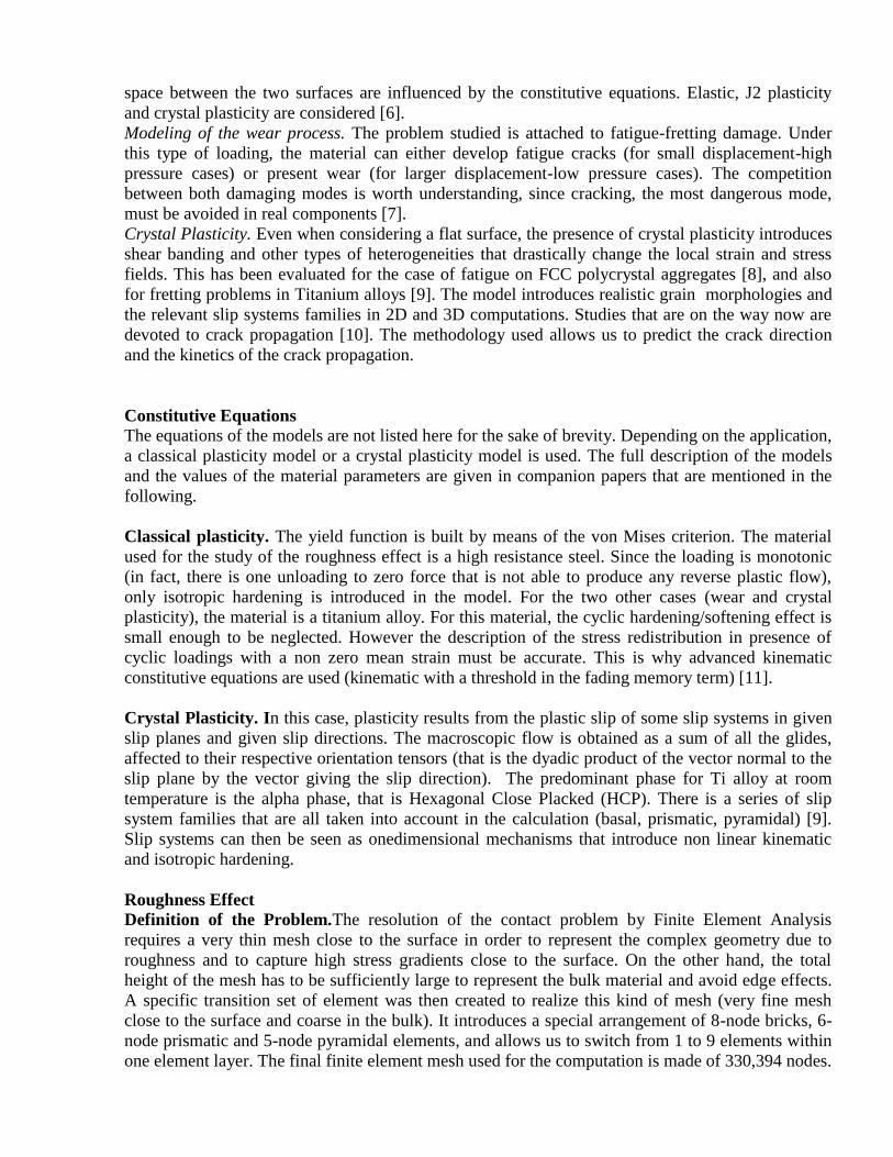
More than 210,000 of them are located in 2 layers constituting a regularly meshed zone adjacent to
the contacting surface (Fig. 1). The rough surface itself consists of 105,625 nodes. The number of
Fig. 1. Finite Element mesh of the rough surface (54 µm x 63 µm)
asperities which belong to the surface is about 230, so that the average number of nodes used for one
asperity is about 460. The mesh is then able to account for local gradients that develop during the
deformation process (see [6]). The normal and frictionless contact between a rough surface and a
rigid plan is then simulated. The normal displacement is fixed on the lateral faces, and a vertical
displacement in the direction of the rigid plane is imposed to the bottom of the mesh. The other
displacements of this face are blocked. The computation is performed through a multi-threading
treatment on four dual-core processor workstation (Intel X5550 2.67GHz) using an Partial Dirichlet-
Neuman technique [13] implemented in the finite element code Zset/Zebulon [14].
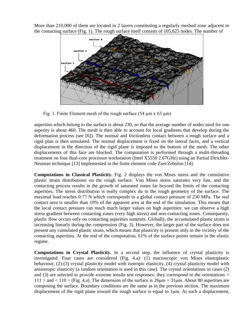
Computations in Classical Plasticity. Fig. 2 displays the von Mises stress and the cumulative
plastic strain distributions on the rough surface. Von Mises stress saturates very fast, and the
contacting process results in the growth of saturated zones far beyond the limits of the contacting
asperities. The stress distribution is really complex du to the rough geometry of the surface. The
maximal load reaches 0.77 N which corresponds to a global contact pressure of 230 MPa. The real
contact area is smaller than 10% of the apparent area at the end of the simulation. This means that
the local contact pressure can reach much larger values on high asperities: we can observe a high
stress gradient between contacting zones (very high stress) and non-contacting zones. Consequenty,
plasfic flow occurs only on contacting asperities summits. Globally, the accumulated plastic strain is
increasing linearly during the compression (Fig. 3). However, the larger part of the surface does not
present any cumulated plastic strain, which means that plasticity is present only in the vicinity of the
contacting asperities. At the end of the computation, 61% of the surface points remain in the elastic
regime.
Computations in Crystal Plasticity. In a second step, the influence of crystal plasticity is
investigated. Four cases are considered (Fig. 4.a): (1) macroscopic von Mises elastoplastic
behaviour, (2)-(3) crystal plasticity model with isotropic elasticity, (4) crystal plasticity model with
anisotropic elasticity (a random orientation is used in this case). The crystal orientations in cases (2)
and (3) are selected to provide extreme tensile test responses: they correspond to the orientations <
111 > and < 110 > (Fig. 4.a). The dimension of the surface is 26μm × 31μm. About 80 asperities are
composing the surface. Boundary conditions are the same as in the previous section. The maximum
displacement of the rigid plane toward the rough surface is equal to 1μm. At such a displacement,
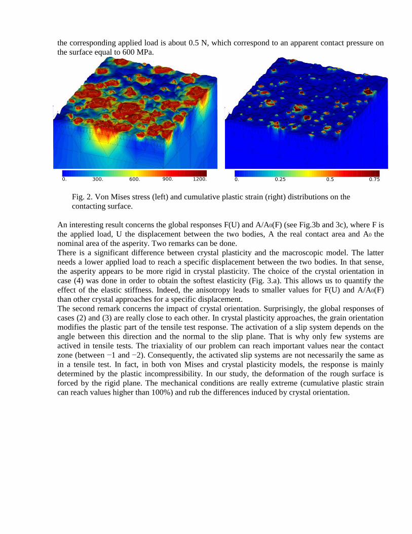
the corresponding applied load is about 0.5 N, which correspond to an apparent contact pressure on
the surface equal to 600 MPa.
Fig. 2. Von Mises stress (left) and cumulative plastic strain (right) distributions on the
contacting surface.
An interesting result concerns the global responses F(U) and A/A0(F) (see Fig.3b and 3c), where F is
the applied load, U the displacement between the two bodies, A the real contact area and A0 the
nominal area of the asperity. Two remarks can be done.
There is a significant difference between crystal plasticity and the macroscopic model. The latter
needs a lower applied load to reach a specific displacement between the two bodies. In that sense,
the asperity appears to be more rigid in crystal plasticity. The choice of the crystal orientation in
case (4) was done in order to obtain the softest elasticity (Fig. 3.a). This allows us to quantify the
effect of the elastic stiffness. Indeed, the anisotropy leads to smaller values for F(U) and A/A0(F)
than other crystal approaches for a specific displacement.
The second remark concerns the impact of crystal orientation. Surprisingly, the global responses of
cases (2) and (3) are really close to each other. In crystal plasticity approaches, the grain orientation
modifies the plastic part of the tensile test response. The activation of a slip system depends on the
angle between this direction and the normal to the slip plane. That is why only few systems are
actived in tensile tests. The triaxiality of our problem can reach important values near the contact
zone (between −1 and −2). Consequently, the activated slip systems are not necessarily the same as
in a tensile test. In fact, in both von Mises and crystal plasticity models, the response is mainly
determined by the plastic incompressibility. In our study, the deformation of the rough surface is
forced by the rigid plane. The mechanical conditions are really extreme (cumulative plastic strain
can reach values higher than 100%) and rub the differences induced by crystal orientation.
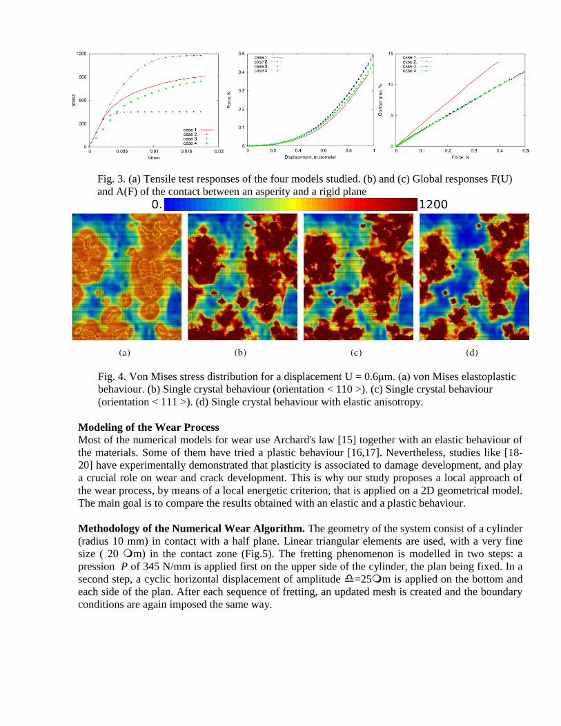
Fig. 3. (a) Tensile test responses of the four models studied. (b) and (c) Global responses F(U)
and A(F) of the contact between an asperity and a rigid plane
Fig. 4. Von Mises stress distribution for a displacement U = 0.6μm. (a) von Mises elastoplastic
behaviour. (b) Single crystal behaviour (orientation < 110 >). (c) Single crystal behaviour
(orientation < 111 >). (d) Single crystal behaviour with elastic anisotropy.
Modeling of the Wear Process
Most of the numerical models for wear use Archard's law [15] together with an elastic behaviour of
the materials. Some of them have tried a plastic behaviour [16,17]. Nevertheless, studies like [18-
20] have experimentally demonstrated that plasticity is associated to damage development, and play
a crucial role on wear and crack development. This is why our study proposes a local approach of
the wear process, by means of a local energetic criterion, that is applied on a 2D geometrical model.
The main goal is to compare the results obtained with an elastic and a plastic behaviour.
Methodology of the Numerical Wear Algorithm. The geometry of the system consist of a cylinder
(radius 10 mm) in contact with a half plane. Linear triangular elements are used, with a very fine
size ( 20 m) in the contact zone (Fig.5). The fretting phenomenon is modelled in two steps: a
pression P of 345 N/mm is applied first on the upper side of the cylinder, the plan being fixed. In a
second step, a cyclic horizontal displacement of amplitude =25m is applied on the bottom and
each side of the plan. After each sequence of fretting, an updated mesh is created and the boundary
conditions are again imposed the same way.

(a) (b)
Fig. 5. The cylinder-plan system used in the study. (a) General mesh and loading conditions.
(b) Wear box initial view and eroded configuration showing the master points (empty circles).
Fig. 6. Comparison between the wear profile for elastic and plastic contitutive equations
The wear process is introduced in the Finite Element code Zset/Zebulon [14]. The Coulomb's law is
used, with a friction coefficient of 0,8 to represent the Ti/Ti interaction. The wear process is applied
on the plan only. The mesh update is not the result of a simple translation. It is obtained by means of
a fully new mesh generation, driven by a list of master nodes located at the surface of the mesh.
These nodes are submitted to a vertical erosion, which amplitude is a function of the local energy
attached to the friction process. According to the procedure, a node i on the impacted surface is
moved from a length given by Archard's rule.
Results and Discussion. The wear profiles presented in Fig. 6 have a similar shape for both types of
constitutive equations. In particular, the amount of material that has been removed for a given
number of cycles is preserved (the curves are shown for 200 to 1000 computed cycles, that is 4000
to 20,000 cycles in the real experiment). Nevertheless, differences can be pointed out: the maximum
depth of the print is larger in elasticity. The size of the contact area is larger in plasticity. HCF and
LCF fatigue models have been applied, in order to predict the number of cycles to initiation, and to
know what is the predominant damage mode [7]. Fatigue life is estimated by using the stress states
computed for each computed cycle. Wear is producing local accommodation in the contact area,
then the predicted number of cycles is larger and larger when the computation is made with the later
estimation. After 1000 computed cycles, the equivalent stress falls below the fatigue limit. This
demonstrates that crack initiation is more likely to occur on the early life, but that the predominant
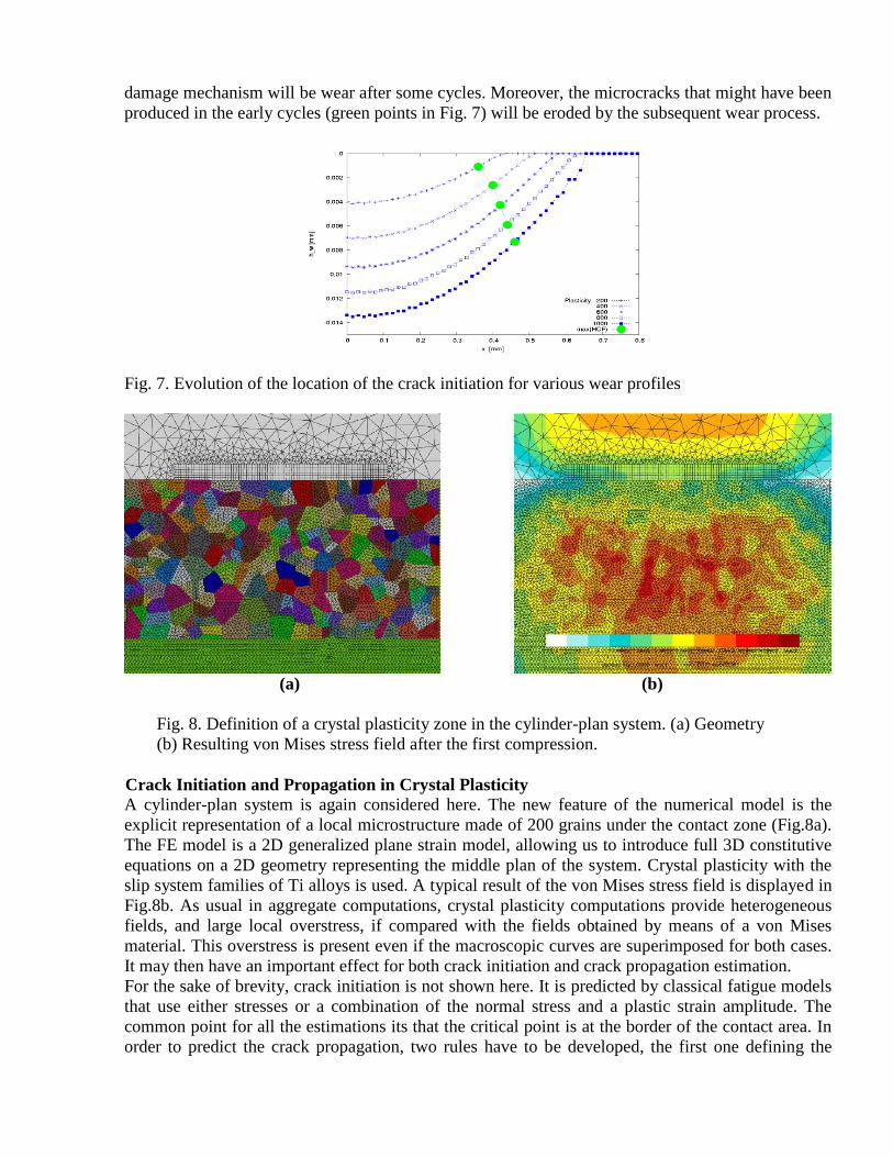
damage mechanism will be wear after some cycles. Moreover, the microcracks that might have been
produced in the early cycles (green points in Fig. 7) will be eroded by the subsequent wear process.
Fig. 7. Evolution of the location of the crack initiation for various wear profiles
(a) (b)
Fig. 8. Definition of a crystal plasticity zone in the cylinder-plan system. (a) Geometry
(b) Resulting von Mises stress field after the first compression.
Crack Initiation and Propagation in Crystal Plasticity
A cylinder-plan system is again considered here. The new feature of the numerical model is the
explicit representation of a local microstructure made of 200 grains under the contact zone (Fig.8a).
The FE model is a 2D generalized plane strain model, allowing us to introduce full 3D constitutive
equations on a 2D geometry representing the middle plan of the system. Crystal plasticity with the
slip system families of Ti alloys is used. A typical result of the von Mises stress field is displayed in
Fig.8b. As usual in aggregate computations, crystal plasticity computations provide heterogeneous
fields, and large local overstress, if compared with the fields obtained by means of a von Mises
material. This overstress is present even if the macroscopic curves are superimposed for both cases.
It may then have an important effect for both crack initiation and crack propagation estimation.
For the sake of brevity, crack initiation is not shown here. It is predicted by classical fatigue models
that use either stresses or a combination of the normal stress and a plastic strain amplitude. The
common point for all the estimations its that the critical point is at the border of the contact area. In
order to predict the crack propagation, two rules have to be developed, the first one defining the
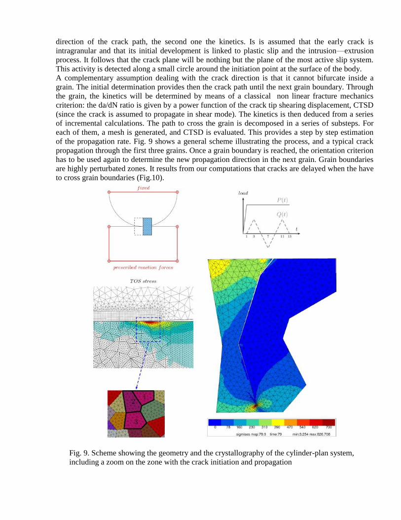
direction of the crack path, the second one the kinetics. Is is assumed that the early crack is
intragranular and that its initial development is linked to plastic slip and the intrusion—extrusion
process. It follows that the crack plane will be nothing but the plane of the most active slip system.
This activity is detected along a small circle around the initiation point at the surface of the body.
A complementary assumption dealing with the crack direction is that it cannot bifurcate inside a
grain. The initial determination provides then the crack path until the next grain boundary. Through
the grain, the kinetics will be determined by means of a classical non linear fracture mechanics
criterion: the da/dN ratio is given by a power function of the crack tip shearing displacement, CTSD
(since the crack is assumed to propagate in shear mode). The kinetics is then deduced from a series
of incremental calculations. The path to cross the grain is decomposed in a series of substeps. For
each of them, a mesh is generated, and CTSD is evaluated. This provides a step by step estimation
of the propagation rate. Fig. 9 shows a general scheme illustrating the process, and a typical crack
propagation through the first three grains. Once a grain boundary is reached, the orientation criterion
has to be used again to determine the new propagation direction in the next grain. Grain boundaries
are highly perturbated zones. It results from our computations that cracks are delayed when the have
to cross grain boundaries (Fig.10).
Fig. 9. Scheme showing the geometry and the crystallography of the cylinder-plan system,
including a zoom on the zone with the crack initiation and propagation
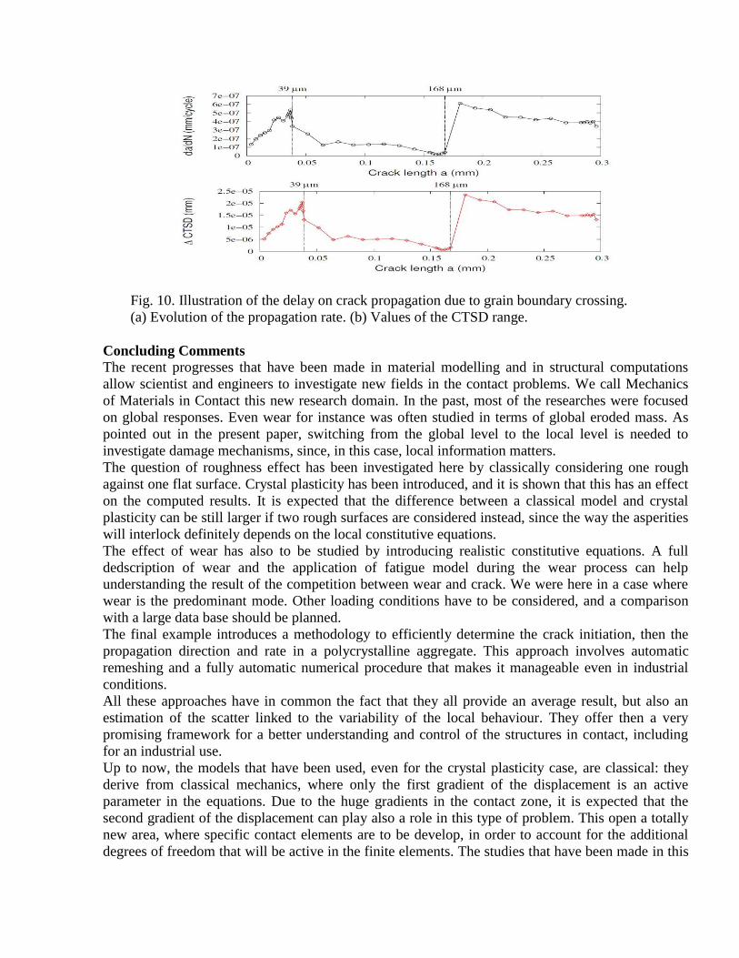
Fig. 10. Illustration of the delay on crack propagation due to grain boundary crossing.
(a) Evolution of the propagation rate. (b) Values of the CTSD range.
Concluding Comments
The recent progresses that have been made in material modelling and in structural computations
allow scientist and engineers to investigate new fields in the contact problems. We call Mechanics
of Materials in Contact this new research domain. In the past, most of the researches were focused
on global responses. Even wear for instance was often studied in terms of global eroded mass. As
pointed out in the present paper, switching from the global level to the local level is needed to
investigate damage mechanisms, since, in this case, local information matters.
The question of roughness effect has been investigated here by classically considering one rough
against one flat surface. Crystal plasticity has been introduced, and it is shown that this has an effect
on the computed results. It is expected that the difference between a classical model and crystal
plasticity can be still larger if two rough surfaces are considered instead, since the way the asperities
will interlock definitely depends on the local constitutive equations.
The effect of wear has also to be studied by introducing realistic constitutive equations. A full
dedscription of wear and the application of fatigue model during the wear process can help
understanding the result of the competition between wear and crack. We were here in a case where
wear is the predominant mode. Other loading conditions have to be considered, and a comparison
with a large data base should be planned.
The final example introduces a methodology to efficiently determine the crack initiation, then the
propagation direction and rate in a polycrystalline aggregate. This approach involves automatic
remeshing and a fully automatic numerical procedure that makes it manageable even in industrial
conditions.
All these approaches have in common the fact that they all provide an average result, but also an
estimation of the scatter linked to the variability of the local behaviour. They offer then a very
promising framework for a better understanding and control of the structures in contact, including
for an industrial use.
Up to now, the models that have been used, even for the crystal plasticity case, are classical: they
derive from classical mechanics, where only the first gradient of the displacement is an active
parameter in the equations. Due to the huge gradients in the contact zone, it is expected that the
second gradient of the displacement can play also a role in this type of problem. This open a totally
new area, where specific contact elements are to be develop, in order to account for the additional
degrees of freedom that will be active in the finite elements. The studies that have been made in this
field will combine constitutive equation, computational contact mechanics, and also new tests, in
order to develop the dialog between theory and experimental observations.
References
[1] J. Lemaitre and J.-L. Chaboche, J.-L., Mechanics of Solid Materials, Cambridge University
Press (1994)
[2] D. François, A. Pineau, A. Zaoui, Mechanical Behaviour of Materials, vol. 1&2, Springer
(2012)
[3] J. Besson, G. Cailletaud, J.-L. Chaboche, S. Forest, Non linear Mechanics of Materials,
Springer, 2010
[4] K.L. Johnson, Contact Mechanics, Cambridge University Press (1994)
[5] I.G. Goryacheva, Contact Mechanics in Tribology, Springer (2011)
[6] V.A. Yastrebov, J. Durand, H. Proudhon and G. Cailletaud, Rough surface contact analysis
by means of the Finite Element Method and of a new reduced model, Comptes Rendus
Mécanique 339:473-490 (2011)
[7] S. Basseville and G. Cailletaud, Wear modelling in fretting with a plastic model: competition
between wear and crack initiation, Proc. Of Colloque Tribology and Sustainable
Development, Aix-en-Provence, France, May 9-11 (2012)
[8] Y. Guilhem, S. Basseville, F. Curtit, J.-M. Stephan, G. Cailletaud, Investigation of the effect
of grain clusters on fatigue crack initiation in polycrystals, International Journal of Fatigue
32:1748–1763 (2011)
[9] T. Dick, S. Basseville, G. Cailletaud, Fatigue modelling in fretting contact with a crystal
plasticity model, Computational Materials Science, 43:36-42 (2008)
[10] Lingtao Sun, H. Proudhon, J.L. Ruiz-Sabariego, G. Cailletaud, Prediction of crack initiation
in fretting problem using the finite element method, in preparation (2012)
[11] J.-L. Chaboche, A review of some plasticity and viscoplasticity constitutive theories, Int. J. of
Plasticity, 24:1642-1693 (2008)
[12] L. Méric, P. Poubanne, G. Cailletaud, Single Crystal Modeling for Structural Calculations.
Part 1: Model Presentation, J. Of Engng Materials and technology, 113:162-170 (1991)
[13] V. Yastrebov, Computational Contact Mechanics, PhD dissertation, Mines ParisTech (2011)
[14] J. Besson, R. LeRiche, R. Foerch, G. Cailletaud, Object--Oriented Programming Applied to
the Finite Element Method, Rev. Eur. Elts Finis, 7:567—588 (1998)
[15] J.F. Archard, Contact and rubbing of flat surfaces, J. of applied Physics, 24:981-988 (1953)
[16] A.L Mohd Tobi, J. Ding, G. Bandak, S.B. Leen, P.H. Shipway, A study on interaction between
fretting wear and cyclic plasticity for Ti-6Al-4V, Wear, 267:270-282 (2009)
[17] L. Feng, J. Xu, The role of plastic anisotropy deformation in fretting wear predictions, Wear,
260:1274-1284 (2006)
[18] A. Kappor, Wear by plastic ratchetting, Wear, 212:119-130 (2001)
[19] S. Fouvry, P. Kapsa, L. Vincent, An elastic-plastic shakedown analysis of fretting wear, Wear,
247:41-54 (2006)
[20] J.M. Ambrico, M.R. Begley, Plasticity in fretting contact, J. of the Mechanics and Physics of
Solids, 48:2391-2417 (2007)
Related Documents