Price: $2.00 Reading Time: 32 Minutes THE MclNTOSH MC 2500 STEREO POWER AMPLIFIER

Welcome message from author
This document is posted to help you gain knowledge. Please leave a comment to let me know what you think about it! Share it to your friends and learn new things together.
Transcript

Price: $2.00 Reading Time: 32 Minutes
THE MclNTOSH MC 2500 STEREO POWER AMPLIFIER

VARIOUS REGULATORY AGENCIES REQUIRE THAT WE BRING THE FOLLOWING INFORMATION TO YOUR ATTENTION. PLEASE READ IT CAREFULLY.
The Mclntosh MC 2500 is an extremely high power amplifier. Because of the high power available it is necessary to emphasize some prudent and safe operating conditions.
1. Loudspeakers can be damaged or destroyed by the high power available from the MC 2500. Never connect or disconnect inputs or outputs while the amplifier is turned on.
2. Never operate the amplifier with the power cord plugged into an auxiliary AC power outlet on source equipment. The amplifier draws 15 amperes and can damage the source equipment.
3. Do not operate the instrument plugged into an ordinary extension cord. A heavy duty extension cord (14 ga. or heavier) is required.
4. Be cautious when lifting the instrument. It weighs 129 pounds. Make certain that what it is placed on can support the weight.
5. The amplifier cooling fans can be thermostatically controlled when the fan switch on the rear panel is placed in the thermally switched positions. When so operated, the fans will not run when the amplifier is cool, as when the amplifier is first turned on. As heat develops, one or both fans will automatically turn on as conditions require. This operating behavior is normal.
WARNING: TO PREVENT FIRE OR SHOCK HAZARD, DO NOT EXPOSE THIS UNIT TO RAIN OR MOISTURE.
The Mclntosh you have purchased is a Model
MC 2500. It has a serial number located on the rear panel
of the chassis. Record that serial number here:
The model, serial number and purchase date are impor
tant to you for any future service. Record the purchase
date here:
Upon application, Mclntosh Laboratory provides a
Three-Year Service Contract. Your Mclntosh authorized
Service Agency can expedite repairs when you provide
the Service Contract with the instrument for repair. To
assist, record your Service Contract number here:
Serial Number
Purchase date
Service Contract Number

Your MC 2500 Stereo Power Amplifier can give you many years of satisfactory performance. If you have any questions, please contact:
CUSTOMER SERVICE Mclntosh Laboratory Inc. 2 Chambers Street Binghamton, New York 13903-9990 Phone: 607-7233512
Contents SERVICE CONTRACT INFORMATION 1
INSTALLATION 2 HOW TO CONNECT 3
FRONT PANEL INFORMATION 8 REAR PANEL INFORMATION 10
PERFORMANCE LIMITS 12 PERFORMANCE CHARTS 13, 14
TECHNICAL DESCRIPTION 15 BLOCK DIAGRAM 17
MclNTOSH THREE YEAR SERVICE CONTRACT An application for A THREE YEAR SERVICE CONTRACT is included with this manual.
The terms of the contract are: 1 Mclntosh will provide all parts, materials
and labor needed to return the measured performance of the instrument to the original performance limits. The SERVICE CONTRACT does not cover any shipping costs to and from the authorized service agency or the factory.
2. Any Mclntosh authorized service agency will repair Mclntosh instruments at normal service rates. To receive service under the terms of the SERVICE CONTRACT, the SERVICE CONTRACT CERTIFICATE must be presented when the instrument is taken to the service agency.
3. Always have service done by a Mclntosh authorized service agency. If the instrument is modified or damaged as a result of unauthorized repair, the SERVICE CONTRACT will be cancelled. Damage by improper use or mishandling is not covered by the SERVICE CONTRACT.
4. The SERVICE CONTRACT is issued to you as the original purchaser. To protect you from misrepresentation, this
contract cannot be transferred to a second owner.
5. To receive the SERVICE CONTRACT, your purchase must be made from a Mclntosh franchised dealer.
6. Your completely filled in application for the SERVICE CONTRACT must be postmarked within 30 days of the date of purchase of the instrument.
7. To receive the SERVICE CONTRACT, all information on the application must be filled in. The SERVICE CONTRACT will be issued when the completely filled in application is received by Mclntosh Laboratory Incorporated in Binghamton, New York.
8. Units in operation outside the United States and Canada are not covered by the Mclntosh Factory Service Contract, irrespective of the place of purchase. Nor are units acquired outside the U.S.A. and Canada, the purchasers of which should consult with their dealer to ascertain what, if any, service contract or warranty may be available locally.
Copyright 1981 © by Mclntosh Laboratory Inc. -1-
Take Advantage of 3 years of Contract Service... Fill in the Application NOW.

Installation
Installation of the MC 2500 requires careful thought about three important factors. They are: the electrical power to operate the unit, the weight, and the heat generated when the MC 2500 is operating.
The MC 2500 draws 15 amperes when operated at full power when amplifying music or speech. Do not use ordinary extension cords. If an extension is used then it must be heavy duty and 14 ga. or heavier. Plug the AC power cord directly into a wall outlet. Make certain that the AC power outlet has at least 15 amperes capacity. Do not plug the MC 2500 into an auxiliary AC power outlet on a preamplifer or other source equipment. If remote power operation is required, an external relay arrangement must be made.
The weight of the instrument is 129 pounds. Make certain that the structure on which it is to be mounted can support that weight.
Adequate ventilation extends the trouble-free life of electronic instruments. It is generally found that each 10° centigrade (18°F) rise in temperature reduces the life of electrical insulation by one half. Adequate ventilation is an inexpensive and effective means of preventing insulation breakdown that results from unnecessarily high operating temperatures. The direct benefit of adequate ventilation is longer, trouble-free life. The heat generated in the operation of the MC 2500 is exhausted from the unit by two temperature controlled low noise, long life fans.
Cooling input air is drawn into the MC 2500 through the ventilation holes on the sides and bottom of the amplifier. The air passes over the transformers, output transistor heat sinks; and, is blown out the back of the instrument by the fans. It is recommended that at least 2 inches of clear space be provided on each side and bottom.
To permit the fans to operate best, provide at least 5 inches of space at the rear of the instrument. A source for input air and a means to exhaust the heated air is necessary so that the heated air does not recirculate through the MC 2500.
RACK INSTALLATION
The MC 2500 may be mounted in a standard 19" rack by removing the aluminum side rails. When rack mounted, the MC 2500 requires 10½ inches of panel space. Allow two inches in front of the panel for the knobs. A depth of 17 inches plus ventilation space is required.
The MC 2500 can be slide mounted in a rack. Tapped weld-nuts and internal structure bracing has been added to both sides of the MC 2500 for use with Model CTS-116 side mounted slide assemblies manufactured by
General Devices Co. Chassis-Trak Div. 525 S. Webster Ave. Indianapolis, IN 46219
-2-

How to Connect INPUT
Stereo operation:
Use shielded cables to connect the signal from the preamplifier or any other signal source to the power amplifier. All connections are made on the back panel of the MC 2500.
For stereo operation, the left output of the preamplifier should be connected to the Left INPUT of the power amplifier. The right output of the preamplifier should be connected to the Right/MONO INPUT of the power amplifier. The MODE SWITCH must be placed in the STEREO position.
To minimize the possibility of hum the shielded leads should be run parallel or loosely twisted together. Locate the cables away from AC power cords.
Monophonic operation:
A shielded cable from the signal source is connected to the Right/MONO input of the MC 2500. The MODE switch on the back panel of the amplifier must be placed in one of the two MONO positions. In these MONO positions the output of the right channel input amplifier is fed to both left and right power amplifiers. The Left INPUT is disconnected. Only the signal fed into the Right/MONO input will be amplified.
OUTPUT
Stereo operation:
To connect the left speaker first check the impedance of the speaker which is usually identified on the speaker itself or in the owner's manual. Connect one lead from the common terminal of the speaker to the LEFT OUTPUT terminal strip screw COMmon. Connect the other terminal of the speaker to the screw with the number corresponding to the speaker impedance on the LEFT OUTPUT terminal strip. The right channel speaker is connected in the same manner on the RIGHT OUTPUT terminal strip. Figure 1 shows the connections for stereo operation.
STEREO LOAD OHMS VOLTS
1 22.4 2 31.6 4 44.7 8 63.2
STEREO OPERATION
CONNECT LOW SIDE OF LOADS TO TERMINALS LEFT COM COM COM COM
RIGHT COM COM COM COM
CONNECT HIGH SIDE OF LOADS TO TERMINALS
LEFT 1W 2W 4W 8W
RIGHT 1W 2W 4W 8W
When multiple speakers are to be connected to either or both outputs, the combined load impedance must be calculated and the load connected to the appropriate impedance tap. The following Figure 2 will aid in selecting the correct impedance match.
Load impedance
in ohms
0.9 to 1.8 1.8 to 3.6
Connect to
1W 2W
Load impedance
in ohms
3.6 to 7.2 7.2 to 14.4
Connect to
4W 8W
Figure 1
Figure 2
If a load impedance is used that is lower than the output impedance tap, then reduced power, increased heating, and possible distortion will result. If a load impedance is used that is higher than the output impedance tap, then the maximum available output is limited.
Make all speaker connections at the amplifier only. For multiple speaker operation, parallel the leads from the speakers to the amplifier.
Because of the high power available from the MC 2500, be sure to use large diameter speaker leads. In all cases, the leads to and from the speaker should be twin conductor or twisted together.
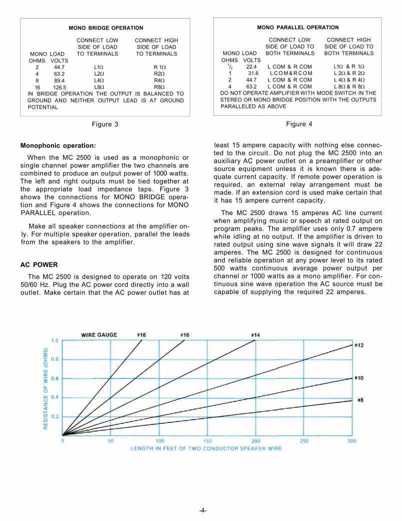
Lamp cord or wire with similar type of insulation can be used to connect the speakers to the amplifier. For the normally short distances of under 20 feet between the amplifier and 8 ohm speakers #18 wire or larger can be used. For distances over 20 feet between the amplifier and speaker use larger diameter wire. Select the correct size wire for the wire distance from the chart (Figure 5 page 4). It is recommended that the DC resistance of the speaker leads not be over 5% of the load impedance. Resistance of the leads must include the length of wire both to and from the speaker or speakers.
-3-
MONO LOAD OHMS VOLTS
2 44.7 4 63.2 8 89.4 16 126.5
MONO BRIDGE OPERATION
CONNECT LOW SIDE OF LOAD TO TERMINALS
L1W L2W L4W L8W
CONNECT HIGH SIDE OF LOAD TO TERMINALS
R 1W R2W R4W R8W
IN BRIDGE OPERATION THE OUTPUT IS BALANCED TO GROUND AND NEITHER OUTPUT LEAD IS AT GROUND POTENTIAL
MONO PARALLEL OPERATION
CONNECT LOW SIDE OF LOAD TO
MONO LOAD BOTH TERMINALS OHMS VOLTS
1/2 22.4 L COM & R COM 1 31.6 L C O M & R C O M 2 44.7 L COM & R COM 4 63.2 L COM & R COM
CONNECT HIGH SIDE OF LOAD TO BOTH TERMINALS
L1W & R 1W L 2W & R 2W L 4W & R 4W L 8W & R 8W
DO NOT OPERATE AMPLIFIER WITH MODE SWITCH IN THE STEREO OR MONO BRIDGE POSITION WITH THE OUTPUTS PARALLELED AS ABOVE
Figure 3 Figure 4
Monophonic operation:
When the MC 2500 is used as a monophonic or single channel power amplifier the two channels are combined to produce an output power of 1000 watts. The left and right outputs must be tied together at the appropriate load impedance taps. Figure 3 shows the connections for MONO BRIDGE operation and Figure 4 shows the connections for MONO PARALLEL operation.
Make all speaker connections at the amplifier only. For multiple speaker operation, parallel the leads from the speakers to the amplifier.
AC POWER
The MC 2500 is designed to operate on 120 volts 50/60 Hz. Plug the AC power cord directly into a wall outlet. Make certain that the AC power outlet has at
least 15 ampere capacity with nothing else connected to the circuit. Do not plug the MC 2500 into an auxiliary AC power outlet on a preamplifier or other source equipment unless it is known there is adequate current capacity. If remote power operation is required, an external relay arrangement must be made. If an extension cord is used make certain that it has 15 ampere current capacity.
The MC 2500 draws 15 amperes AC line current when amplifying music or speech at rated output on program peaks. The amplifier uses only 0.7 ampere while idling at no output. If the amplifier is driven to rated output using sine wave signals it will draw 22 amperes. The MC 2500 is designed for continuous and reliable operation at any power level to its rated 500 watts continuous average power output per channel or 1000 watts as a mono amplifier. For continuous sine wave operation the AC source must be capable of supplying the required 22 amperes.
-4-

Stereophonic Connections
-5-

Mono-Bridge Connections
-6-
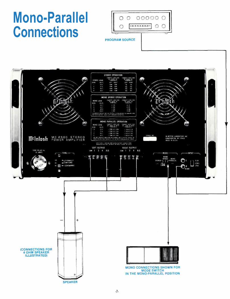
Mono-Parallel Connections
-7-

Front Panel Information METERS
Output power monitor meters indicate the output power of each channel. Each meter has two primary scales: WATTS and DECIBELS. When the METER RANGE switch in one of the decibel (dB) positions, peak signal readings are indicated on the lower DECIBEL scale. When the METER RANGE switch in the WATTS position, direct power in watts is read from the upper WATTS scale. The meters are calibrated to read average watts. The intermediate markings between the calibrations represent, beginning with 500 watts, 200 watts, 100 watts, the indicated 50 watts, 20 watts, 10 watts, the indicated 5 watts, 2 watts, 1 watt, the indicated 0.5 watt, 0.2 watt, 0.1 watt, the indicated 0.05 watt, 0.02 watt, 0.01 watt, the indicated 0.005 watt, 0.002 watt and 0.001 watt. Although the meter calibrations are in average watts for a sine wave signal, the meters electrically respond to signal peaks. The meters are voltage actuated and indicate power accurately when the amplifier is operated into rated output load impedances.
The meters respond to the peak output of each channel. Ordinary meters lack the capability of indicating the short interval information in a sound wave. The mass of the meter movement is too great to respond to the nearly instantaneous changes in
music program material. Short interval information can have a duration as short as half a thousandth of a second. Ordinarily, a meter pointer moving over its scale in such a short time would not be seen. Mclntosh has developed circuits that drive the meters to respond to the short interval information in a sound wave to an accuracy of 90%. The electrical pulse that drives the meter pointer is time stretched long enough so that the peak position of the pointer can register in the persistence of vision characteristic of the retina of the human eye.
LEFT GAIN
The LEFT GAIN control adjusts the volume in the left channel to the desired listening level. Turn the control clockwise to increase the volume.
RIGHT/MONO GAIN
The RIGHT/MONO GAIN control adjusts the volume in the right channel to the desired listening level. Turn the control clockwise to increase the volume. When the output of the MC 2500 is connected for monophonic operation and the rear panel MODE SWITCH in the MONO position, the volume is controlled by the RIGHT/MONO GAIN control only.
-8-

METER RANGE
The METER RANGE switch has five positions.
WATTS
In the WATTS position each meter's primary calibration is from .005 watt (five milliwatts), up to 500 watts, the rated power output of the MC 2500. The meter is calibrated for 1000 watts at the right hand end of the meter scale. While the MC 2500 cannot reach this power level continuously, it is possible for short interval peaks to exceed, considerably, the 500 watt continuous rating.
HOLD
In the HOLD position, each meter indicates WATTS and locks to the highest power peak in a sequence of peaks. The meter will be driven to maximum power and electronically held there until a higher peak passes through the amplifier. If no further peaks are reached the meter needle will very slowly return to its rest position at a decay rate of 6 dB per minute.
DECIBELS (dB)
In the other three positions of the METER RANGE switch the meters will indicate the output of each channel in DECIBELS relative to 500 watts or any other chosen reference. 0 dB In this position of the switch, if the ampli
fier delivers 500 average watts, the meter indicates 0 dB; at 250 average watts the meter indicates - 3 dB. If the amplifier is overdriven to + 2 dB the indicated output would be 792 watts.
- 1 0 dB In this position of the switch, if the amplifier delivers 50 average watts, the meter indicates 0 dB; at 25 average watts the meter indicates -3 dB.
- 2 0 dB In this position of the switch, if the amplifier delivers 5 average watts, the meter indicates 0 dB; at 2.5 average watts the meter indicates -3 dB.
POWER GUARD
POWER GUARD assures that the MC 2500 cannot be overdriven, thus amplifier output clipping is eliminated. Clipping is caused when an amplifier is asked to produce more power output than it can deliver with low distortion. Amplifiers are capable of delivering large quantities of highly distorted power when they are driven to clipping. The extra energy content of the clipped signal will damage most speakers. Mcintosh's Power Guard circuit protects your speakers from this kind of damage. The MC 2500 has a built in "waveform comparator" that compares the wave shape of the output signal to the input signal. If the disparity between the two signals, due to overdrive, exceeds 0.5% (equivalent to 0.5%
total harmonic distortion) a red LIMIT indicator illuminates. With any further increase in distortion the Power Guard circuit operates to limit the amplifier input dynamically so that the amplifier cannot be overdriven. Power Guard eliminates amplifier output clipping. As long as the amplifier operates without overload the NORMAL indicator illuminates.
HEADPHONES
The output of the front panel HEADPHONES jack has been designed to feed low impedance dynamic stereo headphones.
The HEADPHONES output is not affected by the SPEAKERS switch.
SPEAKERS
OFF: The loudspeakers are turned off when the SPEAKER switch is in the OFF position and the red speaker indicator is on.
ON: Music will be heard through the loudspeakers. Use this as the normal listening position. A green speaker light indicates when the speakers are ON.
THE SPEAKER SWITCH MUST BE IN THE "ON" POSITION TO HEAR MUSIC FROM THE LOUDSPEAKERS.
POWER
The power switch turns the MC 2500 ON or OFF. The power switch is also a power input circuit breaker. If the power input to the amplifier exceeds a safe limit the circuit breaker will trip off. To restore power simply place the switch in the OFF position and then to the ON position.
-9-

Rear Panel Information INPUT JACKS
In the stereo mode of operation, both input jacks accept signal. In the mono mode of operation only the Right (MONO) channel input jack accepts signal and the Left channel input jack is disconnected.
INPUT LEVEL
The input sensitivity of the MC 2500 is 0.75 volts or 2.5 V depending on the position of the INPUT LEVEL switch. With indicated voltage applied, the amplifier will deliver its rated power. All Mclntosh preamplifiers have been designed to deliver 2.5 volts output with rated input. For the best signal to noise ratio when using Mclntosh source equipment, always have the INPUT LEVEL switch in the 2.5 V position and the front panel LEFT and RIGHT/MONO GAIN controls in the fully clockwise position. If more gain is desired the 0.75 V position may be used. For source equipment other than Mclntosh, set the switch in the position nearest to the stated output rating of the source equipment.
MODE SWITCH
The MC 2500 will operate in three modes, Stereo, Mono Bridge, and Mono Parallel. The Mono modes
differ in the loads they will drive and the connection sequence to the speaker terminals. A connection chart appears on the rear panel.
LEFT and RIGHT OUTPUT TERMINALS
For stereo operation, output impedances of 1, 2, 4 and 8 ohms have been provided on a secure, screw type barrier strip. For monophonic operation, proper interconnection provides 0.5, 1, 2, 4, 8, and 16 ohms from the same barrier strips. See page 3 for connecting instructions.
FANS SWITCH
Amplifier cooling is accomplished by means of two low noise fans at the rear of the amplifier. Fan operation is controlled by the three position FANS switch. In the THERMALLY SWITCHED LO position the fans do not operate when the amplifier is cool, as when the amplifier is first turned on. As heat develops, one or both fans will automatically turn on to low speed operation as conditions require. Operation in this position of the switch produces the lowest fan noise. Adequate cooling will be provided for all normal operating conditions.
The THERMALLY SWITCHED HI switch position functions like the LO position but the fans operate at
-10-

a high speed under thermal control. The CONTINUOUS HI position makes the fans operate continuously at high speed whenever the amplifier is turned on. These two switch positions can be used for industrial applications or where severe operating conditions are present. Amplifier reliability is enhanced by low operating temperatures.
Should the cooling air be blocked or should the amplifier operating temperature become too high, thermal cutouts within the amplifier will turn off the power to the amplifier. The fans will continue to operate. When the amplifier has cooled it will automatically turn on again.
AC POWER
The MC 2500 is designed to operate on 120 volts 50/60 Hz. The amplifier draws 15 amperes line current when amplifying music or speech at rated output on program peaks. The amplifier uses only 0.7 ampere while idling at no output. If the amplifier is driven to rated output using sine wave signals it will draw 22 amperes. The MC 2500 is designed for continuous and reliable operation at any power level to its rated 500 watts continuous average power output per channel or 1000 watts as a mono amplifier. For continuous sine wave operation the AC source must be capable of supplying the required 22 amperes.
-11-

Performance Limits PERFORMANCE GUARANTEE
Performance Limits are the maximum deviation from perfection permitted for a Mclntosh instrument. We promise you the MC 2500 you buy must be capable of performance at or exceeding these limits or you get your money back. Mclntosh is the only manufacturer that makes this guarantee.
PERFORMANCE Mclntosh audio power ratings are in accordance
with the Federal Trade Commission Regulation of November 4, 1974 concerning power output claims for amplifiers used in home entertainment products.
POWER OUTPUT STEREO 500 watts minimum sine wave continuous average power output, per channel, both channels operating into 1 ohm, 2 ohms, 4 ohms, or 8 ohms load impedance, which is: 22.4 volts RMS across 1 ohm 31.6 volts RMS across 2 ohms 44.7 volts RMS across 4 ohms 63.2 volts RMS across 8 ohms
MONO 1000 watts minimum sine wave continuous average power output into 0.5 ohm, 1 ohm, 2 ohms, 4 ohms, 8 ohms, or 16 ohms load impedance, which is: 22.4 volts RMS across 0.5 ohm 31.6 volts RMS across 1 ohm 44.7 volts RMS across 2 ohms 63.2 volts RMS across 4 ohms 89.4 volts RMS across 8 ohms
126.5 volts RMS across 16 ohms OUTPUT LOAD IMPEDANCE STEREO 1 ohm, 2 ohms, 4 ohms, and 8 ohms; separate terminals are provided for each output. MONO-PARALLEL 0.5 ohm, 1 ohm, 2 ohms, and 4 ohms; obtained by connecting in parallel the appropriate terminals of both channels. MONO-BRIDGED 2 ohms, 4 ohms, 8 ohms, or 16 ohms; obtained by connecting to the output terminals of both channels. The bridged output is balanced to ground. Neither side is grounded. RATED POWER BAND 20 Hz to 20,000 Hz TOTAL HARMONIC DISTORTION STEREO 0.02% maximum harmonic distortion at any power level from 250 milliwatts to 500 watts per channel from 20 Hz to 20,000 Hz, both channels operating. MONO 0.02% maximum harmonic distortion at any power level from 250 milliwatts to 1000 watts from 20 Hz to 20,000 Hz.
INTERMODULATION DISTORTION STEREO 0.02% maximum if instantaneous peak power output is 1000 watts or less per channel with both channels operating for any combination of frequencies, 20 Hz to 20,000 Hz. MONO 0.02% maximum if instantaneous peak power output is 2000 watts or less for any combination of frequencies, 20 Hz to 20,000 Hz. FREQUENCY RESPONSE (at one watt output) 20 Hz to 20,000 Hz +0 -0.25 dB. 10 Hz to 100,000 Hz + 0.25 - 1 dB. NOISE AND HUM 95 dB below rated output.
RATINGS DAMPING FACTOR Greater than 30 INPUT IMPEDANCE 50,000 ohms. INPUT SENSITIVITY Switchable: 0.75 volt or 2.5 volts—Level control provided for higher input voltages. POWER GUARD THD not to exceed 2% with up to 20 dB overdrive at 1 kHz.
GENERAL INFORMATION POWER REQUIREMENTS 120 Volts 50/60 Hz 0.7 to 22 amps., 15 amps UL/CSA SEMICONDUCTOR COMPLEMENT 91 silicon transistors 35 silicon rectifiers and diodes
6 integrated circuits
MECHANICAL INFORMATION SIZE Front panel measures 19 inches wide (48.26 cm) by 10½ inches high (26.67 cm). Chassis measures 17 inches wide (43.18 cm) by 10 inches high (25.4 cm) by 17 inches deep (43.18 cm), including connectors. Clearance in front of mounting panel including knobs 2 inches (5.08 cm) FINISH Front panel is anodized gold and black. Chassis is black baked enamel. MOUNTING Standard 19" (48.26 cm) rack mounting WEIGHT 129 pounds (58.5 kg) net, 144 pounds (65.3 kg) in shipping carton
-12-
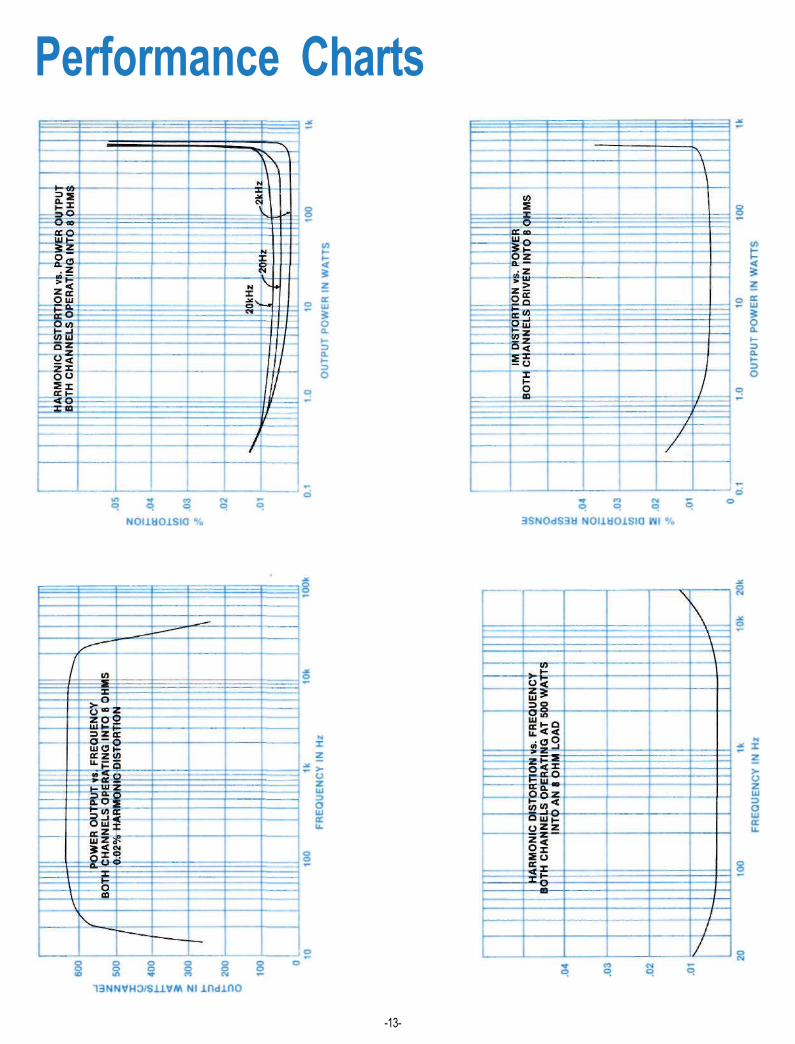
Performance Charts
-13-

-14-

Technical Description INPUT AMPLIFIER
Each channel input contains a complete seven transistor low power amplifier. A differential transistor pair provides high input impedance and low noise. The differential signals are combined in a current mirror circuit which drives a class A amplifier stage. The following output stage is a complementary pair of transistors with class AB biasing. The output signal drives the metering circuit, headphone jack, and the high power output amplifier. This discrete transistor amplifier design was selected for low noise, low distortion, adequate power output capability to drive headphones, and freedom from turn on and turn off transients.
The INPUT LEVEL selector and GAIN controls are passive attenuators which precede the input amplifier circuitry. Therefore, the input system to the amplifier cannot be overloaded when the controls are correctly set.
In the MONO mode of operation the input signal feeds only the right input amplifier via the RIGHT/MONO GAIN control. The output of the right input amplifier feeds both output power amplifier sections. When MONO BRIDGE MODE is selected the left channel input amplifier is used as a phase inverter before the left output amplifier. The output channels are therefore 180° out of phase with respect to each other which is the correct arrangement for bridge output connections. When MONO PARALLEL MODE is selected the channels operate in phase. The channels, of course, also operate in phase for the STEREO MODE.
OUTPUT POWER AMPLIFIER The power amplifier inputs are coupled to the in
put amplifier outputs through an electronic switch. The switch eliminates turn-on and turn-off transients and is used for speaker switching. A junction FET and LED/light dependent resistor network make up the switch. This combination allows the lowest possible distortion when the amplifier is on and high isolation when the output power amplifier is off. The control signal to the switch is held off during the turn-on delay period. Therefore, transients that may come into the amplifier from source equipment will not be amplified or reach the loudspeaker. Since the HEADPHONE output and meters are powered by the input amplifier, their operation is not affected by the SPEAKER switch or turn on delay system.
The first stage of the output power amplifier is a differential transistor pair biased for best linearity. The offset to the differential pair is adjustable. Correct adjustment allows the lowest possible distor
tion at low frequencies. A current mirror circuit combines the differential outputs into one signal which is then amplified by a following class A voltage amplifier. Both the differential transitors and the voltage amplifier are supplied by active current sources. The results are lower distortion and cleaner turn on characteristics.
The driver stage consisting of a complimentary pair of power transitors biased class AB follow the voltage amplifier. Next, six complimentary pairs of rugged power transistors make up the power output stage. All power transistors are mounted on conservatively sized anodized aluminum heat sinks. Because of a unique connection of the bias network, the output transistors operate class B and exhibit no crossover distortion often associated with class B operation. The heat sinks, therefore remain cool when there is no output. During heavy demands, temperature controlled fans keep the heat sinks cool.
The amplifier output signal is fed to the output terminals through the output autotransformer. The Mclntosh designed interleaved multifilar wound autotransformer is used to properly match the amplifier to stereo output load taps for 1, 2, 4 and 8 ohms. The MC 2500 will deliver full power over the entire audio frequency range at any of these impedances. The autotransformer also protects speakers from damage in the event of amplifier failure. Should a direct current component appear in the output it is shunted by the autotransformer and DC cannot damage the speaker.
A Mclntosh patented Sentry Monitoring circuit constantly monitors the output signal and instantly reacts to prevent overload of the output transistors. At signal levels up to rated output this circuit has high impedance and has no effect upon the output. If the power output exceeds design maximum, the Sentry Monitoring circuit operates to limit the signal to the output transistors. In the event of a short circuit across the amplifier output or severe impedance mismatch the Sentry Monitoring circuit will protect the output transistors from failure. Both positive and negative halves of the output signal are monitored and protected independently.
POWER GUARD PROTECTION CIRCUIT The Mclntosh patented Power Guard circuit
eliminates amplifier clipping due to overdrive. The circuit also illuminates red LIMIT indicator lamps when the amplifier is driven beyond its maximum output capacity. Power Guard prevents loudspeaker damage and eliminates harsh output distortion caused by amplifier clipping.
-15-
The Power Guard circuit consists of a waveform comparator which monitors the wave shape of the amplifier input and output signals. Normally there is no disparity between these signals and the comparator produces no output. When the amplifier is driven beyond its maximum power capacity a difference will develope. If the disparity exceeds 0.5% (equivalent to 0.5% total harmonic distortion) the comparator output causes the red LIMIT indicators to light. If there is a further increase in the disparity the comparator output controls an electronic attenuator at the amplifier input to reduce the amplifier gain, thus holding the amplifier output to its maximum undistorted value regardless of the degree of overdrive to the amplifier. The amplifier may be overdriven by 20 dB before the output distortion exceeds 2%.
The comparator is an especially compensated operational amplifier integrated circuit. Its output is detected by a full wave bridge that feeds signals to the control circuitry for the LIMIT and NORMAL indicators and to the electronic attenuator at the amplifier input. The attenuator is a light emitting diode/light dependent resistor network selected especially for its low distortion and time constant characteristics.
METER CIRCUIT The meter circuit has three basic sections: a loga
rithmic amplifier, a full wave rectifier, and a DC amplifier. In the WATTS ranges, the logarithmic amplifier is used. In the DECIBEL ranges, the signal bypasses this amplifier and goes directly to the full wave rectifiers through an attenuator which is controlled by the METER RANGE switch.
The logarithmic amplifier consists of a high gain operational amplifier with a biopolar connected silicon diode pair as feedback elements. These diodes have a uniform logarithmic characteristic over an 80 dB range. Only 60 dB of this logarithmic range is used in the MC 2500.
The full wave rectifier circuit uses an operational amplifier with silicon diode feedback networks. This amplified diode circuit has nearly perfect rectification characteristics. One rectifier detects only positive signals. The other responds only to negative signals and produces a positive output. The outputs of the rectifiers are combined at the operational amplifier output, so the highest signal, either positive or negative, is the one that is indicated by the meters. Gate diodes are used to charge a low leakage capacitor which attains and holds a charge during signal peaks. The operational amplifier provides a large amount of current so the capacitor can charge suddenly. The charge on the peak holding capacitor is amplified in a two transistor DC amplifier which is used to drive the meter. From the output of this amplifier there is a DC feedback network that connects back to the detector to assure
excellent overall linearity and frequency response. The current drive to the meters has a peaking capacitor to accelerate the upscale response of the meter needle. The meters also have a parallel shunt resistor to correctly damp their action. In the WATTS mode the discharge of the peak holding capacitor is controlled by a resistor current source. In WATTS HOLD, the resistor is disconnected so the peak reading is retained. The rate of decay is about 6 dB per minute.
POWER SUPPLY The power supply is a conventional full wave
bridge rectifier arrangement providing plus and minus 50 volts DC. Electronic regulators step down and regulate plus and minus 15 volt sources for low level circuits. Thermistors are used in the power transformer primary circuit to limit the turn-on current.
-16-


MclNTOSH LABORATORY INC. 2 CHAMBERS ST., BINGHAMTON, N.Y. 13903-9990
607-723-3512 The continuous improvement of its products is the policy of Mclntosh Laboratory Incorporated who reserve the right to
improve design without notice. Printed in U.S.A.
039292
Related Documents