LEADER DIGITAL CINEMA SYSTEMS, INC www.leadercinema.com 213.359.8129 The Maui Project A Technical Summary Part 1: The Living Room System Part 2: The Studio in Paradise draft document © Original Text and Materials by Leader Cinema Systems, all other images, logos and trademarks are the property of their legal owners. This document contains confidential and proprietary information which is the sole property of the author Leader Cinema Systems, Inc. Application of this data and engineering concepts, reverse engineering to learn of industry “secrets” to be incorporated into any system or design not authorized by Leader is strictly forbidden and may result in legal penalties. The Leader Wave Plug Logo, LHF Block Logo and Leader Hollywood Format(tm) are the trademarks of Leader D Cinema Systems, Inc. All World Rights Reserved 1997

Welcome message from author
This document is posted to help you gain knowledge. Please leave a comment to let me know what you think about it! Share it to your friends and learn new things together.
Transcript

LEADER DIGITAL CINEMA SYSTEMS, INC
www.leadercinema.com
213.359.8129
The Maui Project
A Technical Summary
Part 1: The Living Room System
Part 2: The Studio in Paradise
draft document
©© OOrriiggiinnaall TTeexxtt aanndd MMaatteerriiaallss bbyy LLeeaaddeerr CCiinneemmaa SSyysstteemmss,, aallll ootthheerr iimmaaggeess,, llooggooss aanndd ttrraaddeemmaarrkkss aarree tthhee pprrooppeerrttyy ooff tthheeiirr lleeggaall oowwnneerrss.. TThhiiss ddooccuummeenntt
ccoonnttaaiinnss ccoonnffiiddeennttiiaall aanndd pprroopprriieettaarryy iinnffoorrmmaattiioonn wwhhiicchh iiss tthhee ssoollee pprrooppeerrttyy ooff tthhee aauutthhoorr LLeeaaddeerr CCiinneemmaa SSyysstteemmss,, IInncc.. AApppplliiccaattiioonn ooff tthhiiss ddaattaa aanndd
eennggiinneeeerriinngg ccoonncceeppttss,, rreevveerrssee eennggiinneeeerriinngg ttoo lleeaarrnn ooff iinndduussttrryy ““sseeccrreettss”” ttoo bbee iinnccoorrppoorraatteedd iinnttoo aannyy ssyysstteemm oorr ddeessiiggnn nnoott aauutthhoorriizzeedd bbyy LLeeaaddeerr iiss ssttrriiccttllyy
ffoorrbbiiddddeenn aanndd mmaayy rreessuulltt iinn lleeggaall ppeennaallttiieess.. TThhee LLeeaaddeerr WWaavvee PPlluugg LLooggoo,, LLHHFF BBlloocckk LLooggoo aanndd LLeeaaddeerr HHoollllyywwoooodd FFoorrmmaatt((ttmm)) aarree tthhee ttrraaddeemmaarrkkss ooff
LLeeaaddeerr DD CCiinneemmaa SSyysstteemmss,, IInncc.. AAllll WWoorrlldd RRiigghhttss RReesseerrvveedd 11999977

2
The Leader Hollywood Format(tm) Maui Project [DRAFT]
September 21, 1997 (C) Leader Cinema Systems, Inc All World Rights Reserved
The resulting Leader Hollywood Format(tm) Living Room sound system weighs 3.5 tons / 7000
pounds or 3182 Kgs. And now, the rest of the story..........
Both the Living Room and Studio LHF(tm) systems are now finally complete. Spanning 6 years
since we first met with the client and due to construction delays, the results represent a
crowning achievement in electro-acoustic science together with simply staggering degrees of
musical “high-fidelity”. The end result is something to behold across all musical genres. The
most demanding Hollywood studio movie sound-track mixes are reproduced across a power
bandwidth and transparency the equal of the best Hollywood dubbing stages. Studio grade
music playback rivals the best-of-the-best international studios to include Toshiba/EMI Tokyo
and Air Lyndhurst London among two dozen others. It is almost impossible to discuss the
“sound” for the expansiveness of the space together with sophisticated methods of acoustical
treatment, the sound experience is indeed one that needs to be “experienced”.

3
The Residence and The Background:
Bruce Dunbar and his wife Christine are among the world’s most demanding and
knowledgeable clients. Bruce (Masters in Music) has been David Bowie’s manager for 18 years.
He is the secret behind Bowie’s success and from a business perspective, it was Bruce’s
background in finance and management that created over two billion dollars of net worth for
Bowie. Christine with her degrees in Choreography is one of the New York stages leading
choreographers. As a gifted pianist, the couple has worked with the worlds leading industry
professionals. They represent the ideal client for us at Leader Inc.
Master Bedroom and Office Suite entire floor
<< OCEAN 16 feet Side view of the residence / Main Floor Open Plan
Overall Main Floor area: 2800 sq ft / 260 Sq Meters
Studio: 530 sq ft / 49 Sq Meters
The Dunbar’s have lived on the island of Maui Hawaii for over 21 years. Bruce commutes to
New York on a regular basis. When not sitting on a plane, the phone lines buzz non-stop from
“Paradise” to New York or to London England. They secured a choice piece of waterfront
property in the South West corner of Maui in 1990. Located just a few steps from the Maui
Prince Hotel at Makena Beach the Dunbar triangular shaped property proved a challenge for
five architects. None could create that magical result to suite the stunning setting. Then
Bruce is introduced to the Canadian architect Arthur Erickson. Erickson’s international
accomplishments include: The Canadian Embassy Washington DC, The San Diego Convention
Center, King Faisal University Saudi Arabia, Kuwait Oil Sector Complex, Etisalat Tower Abu
Dhabi and over 500 projects world wide. Erickson’s abilities by far out weigh the others. Most
of us can “hear” around corners. Arthur can, I am sure, “see” around multiple corners. His

4
visionary creative genius created an ultra modern concrete residence clad in expansive glass,
as if a land yacht had been frozen in time.
The Dunbar’s were understandably delighted with the outcome. More than a residence, it
became indeed a work of art.
Christine and Bruce live in the world of art. Their business is music...very much an art. The
resulting two Leader Hollywood Format(tm) sound systems and theater are world-class tools
created for international super star professionals. When Christine is working out a dance
routine for a major Broadway or TV show, the music tracks are delivered to her from the
studios on DAT (Digital Audio Tape), CD or ¼” tape at 15 IPS. These studio quality masters
are reproduced at “live you are there” volume levels. The energy in the musical sequences is
reproduced faithfully. It actually both feels and sounds as if a 25 piece orchestra is in the

5
living room (the open plan space totals 2800 sq ft / 260 sq meters). The second LHF(tm) studio
system is located on the ground floor level which contains the sound isolated and floating
music studio.
Bruce critically evaluates mixes sent to him by Bowie and other colleagues from around the
world. Studio Reel-to-Reel tape is also a format in addition to DAT and CD. The playback
system is compatible with numerous large scale “tracking” studio monitoring systems found in
the worlds leading studios. The layers in a mix together with the extended power bandwidth at
the frequency extremes take on dimensions impossible to reproduce on conventional consumer
sound systems. This system will faithfully deliver peak levels to 138 dB SPL per main screen
channel with headroom capabilities. We limit the peak level to 124 dB SPL per channel, which
creates at least 14 dB of headroom ! = Cool Running and reliability.
The result is one of the world’s most highly evolved multi-channel sound systems to be found
anywhere, and here it is, in the middle of the Pacific Ocean.
Behind the Scenes and Development
The client was obviously motivated to have a stellar musical playback and cinema system
created for the massive open-plan living room space spanning 2800 sq feet or 260 sq meters.
The exceptional demands put upon the architect by Bruce prior to Leader being involved in the
project posed a very challenging series of events. Bruce had discussed his needs with the
world’s leading manufacturers of sound systems. None could guarantee that a successful
result would provide the quality of sound for both music and movies to be reproduced from the
same sound system. Lacking from the discussion with over 20 companies was any acoustical
design elements for an exceptionally complex acoustical space. Hard surfaces almost
everywhere, over 120 lineal feet / 36 lineal meters of retractable glass walls, concrete floors and
a hard ceiling.
Bruce was introduced to Emmy Award winner Michael Leader in 1991.
The results of this most positive meeting illustrated to both Bruce and
Architect Erickson a direction. The rooms orientation and acoustical
modifications suggested by Leader served as the foundation for success. It
was readily apparent to Erickson and his lead architect and designer
Michel LaFlamme that this was to become no ordinary living room.

6
Michael Leader had trumped the original living room design concept; he
rotated the rooms interior by 90 degrees along with a series of modifications.
It took an additional 14 months for Leader Acoustic Labs and Leader Cinema Systems to be
awarded the contract. Subsequent to Bruce’s quest to find the ultimate, his world travels
enabled him to further discuss this project with speaker manufacturers. His pointed
questions, because of meeting Michael, when put to these companies were frequently met with
blank faces and stares, no answers, or a contradiction of responses from a previous meeting
Dunbar might have had with them. In short, the obvious was that out of 23 world “renowned”
companies, none had the demonstrated background in the successful implementation of such
systems. Late in 1992 Leader won, it was a great Christmas present for us.
The Living Room
We were elated to have the opportunity to create a masterful system, which would be installed
into an acoustically large space. Contrary to the simplistic view that the 1540 Sq Feet / 143
Sq Meters of retractable glass walls would have a serious deleterious effect upon the sound,
quite the opposite was the result.
Speaker Wall>>>>> a
The other highly desirable aspect of this large space, was unlike typical rooms where adjacent
walls are positioned in close proximity to speaker systems causing multiple reflections and
phantom images, this was not the case here on Maui. The walls to the left (Position “A”) and
right (Position “D”) of the “Main Stage” Left-Center-Right speaker systems are almost 24 feet /
7.3 meters distant from each side. Due to the use of specialized “wave guides” on the mid and
high frequency sections, off-axis energy is controlled such that the sound energy heading in the
direction of the side glass wall is well down in level. More on this follows in the technical
section.
The enormity of the entire space approaching 28,000 Cu Feet / 793 Cu Meters represented
acoustic territory that would result in a huge benefit in the creation of sublime excellence.
7
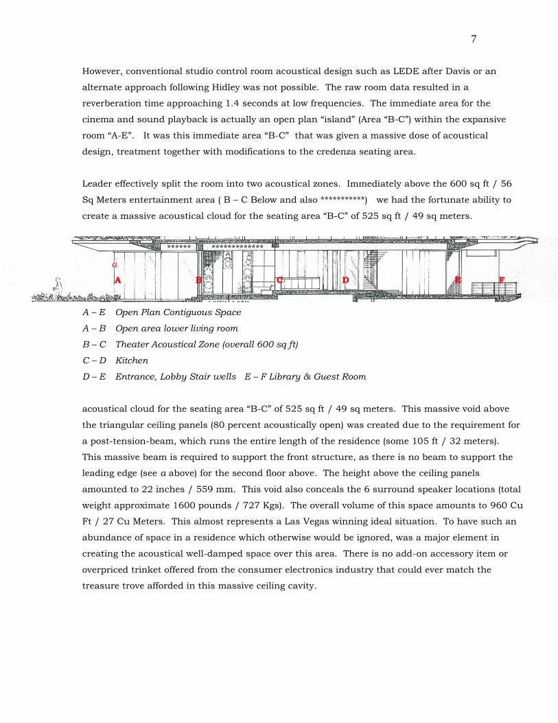
However, conventional studio control room acoustical design such as LEDE after Davis or an
alternate approach following Hidley was not possible. The raw room data resulted in a
reverberation time approaching 1.4 seconds at low frequencies. The immediate area for the
cinema and sound playback is actually an open plan “island” (Area “B-C”) within the expansive
room “A-E”. It was this immediate area “B-C” that was given a massive dose of acoustical
design, treatment together with modifications to the credenza seating area.
Leader effectively split the room into two acoustical zones. Immediately above the 600 sq ft / 56
Sq Meters entertainment area ( B – C Below and also ***********) we had the fortunate ability to
create a massive acoustical cloud for the seating area “B-C” of 525 sq ft / 49 sq meters.
****** *************
a
A B C D E F
A – E Open Plan Contiguous Space
A – B Open area lower living room
B – C Theater Acoustical Zone (overall 600 sq ft)
C – D Kitchen
D – E Entrance, Lobby Stair wells E – F Library & Guest Room
acoustical cloud for the seating area “B-C” of 525 sq ft / 49 sq meters. This massive void above
the triangular ceiling panels (80 percent acoustically open) was created due to the requirement for
a post-tension-beam, which runs the entire length of the residence (some 105 ft / 32 meters).
This massive beam is required to support the front structure, as there is no beam to support the
leading edge (see a above) for the second floor above. The height above the ceiling panels
amounted to 22 inches / 559 mm. This void also conceals the 6 surround speaker locations (total
weight approximate 1600 pounds / 727 Kgs). The overall volume of this space amounts to 960 Cu
Ft / 27 Cu Meters. This almost represents a Las Vegas winning ideal situation. To have such an
abundance of space in a residence which otherwise would be ignored, was a major element in
creating the acoustical well-damped space over this area. There is no add-on accessory item or
overpriced trinket offered from the consumer electronics industry that could ever match the
treasure trove afforded in this massive ceiling cavity.
8
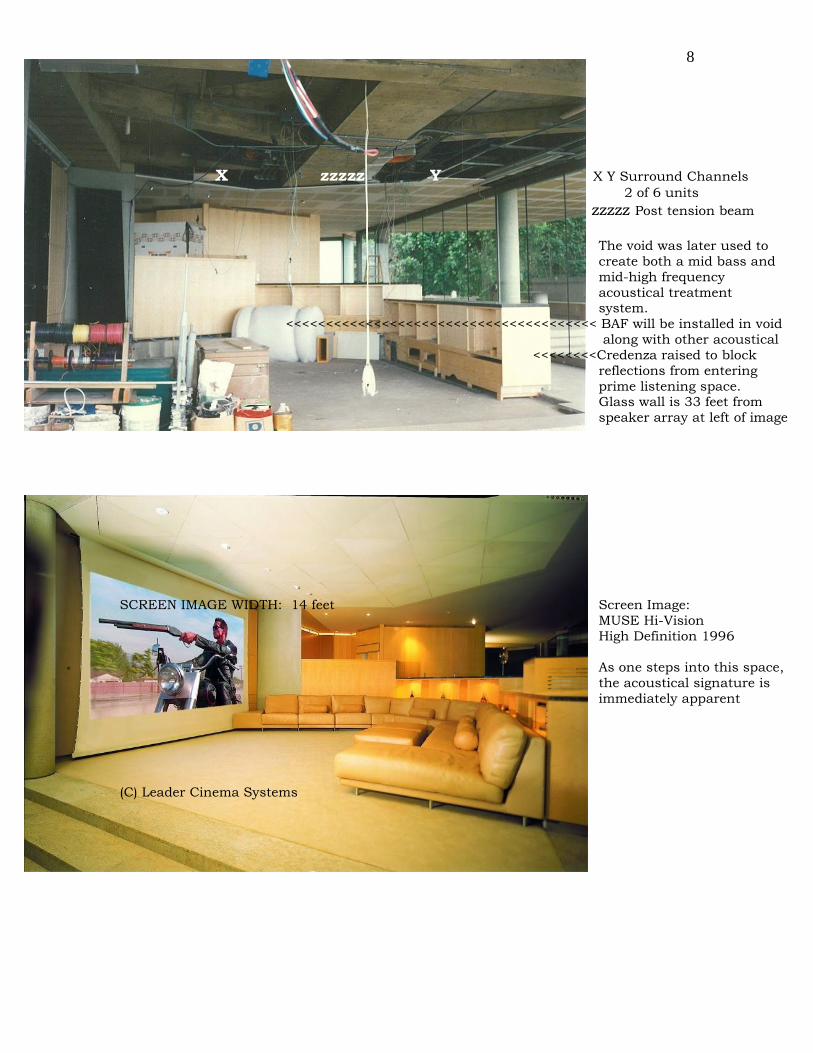
X zzzzz Y X Y Surround Channels
2 of 6 units
zzzzz Post tension beam
The void was later used to
create both a mid bass and
mid-high frequency
acoustical treatment system.
<<<<<<<<<<<<<<<<<<<<<<<<<<<<<<<<<<<<<<< BAF will be installed in void
along with other acoustical
<<<<<<<<Credenza raised to block
reflections from entering
prime listening space. Glass wall is 33 feet from
speaker array at left of image
SCREEN IMAGE WIDTH: 14 feet Screen Image:
MUSE Hi-Vision
High Definition 1996
As one steps into this space,
the acoustical signature is
immediately apparent
(C) Leader Cinema Systems

9
The early design phase during 1992 revealed that such a luxury of space would eliminate low-
frequency standing waves, which are all too common in normal sized rooms. Such “normal”
small sized rooms color the sound resulting in “boomy” low frequencies. The Maui living
room’s irregular shape provides additional low frequency diffusion in addition to venting low
frequency energy down the hall and into stairwells, a natural “bass trap”. As the room is not
“air tight” desirable low frequency “leakage” is permitted through the rubber mullions between
the movable glass panels, as these do not seal 100%. Therefore the low frequency performance
of this amazing room is such that the low frequencies are both visceral, heard and
experienced then dissipate without causing annoying reflections. With the entire glass system
open, the effect does not change radically, proving that there is both sufficient low frequency
control as the low frequency energy disperses down to areas D to E and stair wells.
Treatment Treatment and Surrounds
A B C D
L Ctr R
A to D is open contiguous space approx 60 feet /18.3 meters
Unlike “normal rooms” there is no wall at positions “B” and “C”
A to B is approx 24 feet / 7315 mm Theater Area B-C approx 22 feet / 6705 mm
Speaker position at L and R do not have any wall reflections which are prominent in “normal” rooms
Consequently the acoustically controlled area B – C is a “reflection free zone” operating as LEDE
The Mid Band and High Frequency Rt60 (reverberation time) is 00.26 seconds
All enclosed 6-sided rooms (4 walls, floor and ceiling) and typical small rooms in particular as
found in “normal” residences create complex (undesirable) room resonances. Phantom mirror
images are created due to wall reflections in addition to “modal room resonances” across axial,
tangential and oblique dimensions of any room. Suffice to say, that larger rooms with critical
attention paid to acoustical treatment will always outperform small rooms.
The physical construction of the living room and indeed the entire residence is concrete, glass
and steel. The book case, credenza and seating area is as solid as a rock. During our low

10
frequency slow sweep vibration tests nothing in this room either buzzes or rattles, and the few
items that did, namely a few of the triangular ceiling panels, were promptly fixed.
The massive speaker arrays comprising the Main Screen Channels (Left-Center-Right) have an
overall weight in the range of 2250 pounds / 1.125 tons / 1022 Kgs. They are resiliently
mounted from the concrete wall and each of the five (5) enclosures is completely isolated from
the cabinetry and acoustically transparent door systems. The entire area has the 5 speaker
enclosures “soffit” mounted in a quasi LEDE arrangement, where the entire front face of the
critical mid and high frequency enclosures is acoustically treated to eliminate all “early
reflections” otherwise often referred to as “edge diffraction effects”. The doors are acoustically
transparent.
L<<<<<< >>>>R
Sl Sc Sr
Note the “toe in” of the Left and Right Speakers.
The stereo imaging in L/R stereo music playback
results in pin-point imaging accuracy with a very
wide “sweet spot” When seated at “S” the stereo
image extends as shown. The “effective stereo image”
width at the main seating position is 24 feet / 7.3 meters.
The Directivity Index Di in the mid/hi band is 11.3dB and
is the key to the stability in L&R imaging. See page: XXXX
The camera view in the photo at right, ” represents a
position which would appear to be beyond the area to create a worth while “stereo” image. In fact, as in the “Sr” example above, the sound stage appears to extend beyond the left and right speaker systems. This contributes to the expansive nature of not only Sl Sc Sr the Left and Right channels, but in “Cinema” mode the acoustical summation between the Center, Left and Right arrays becomes a seamless transition.
a listening position

11
The six (6) surround channels are located above the acoustically transparent 80% open
expanded metal triangular ceiling panels. Each is a 15 inch 2 way bi-amplified system with a
weigh of 235 Lbs / 107 Kgs for a total of 1410 lbs / 641 Kgs.
Width of face = 48” / 1219mm LCS 1502-6.8-32 SF 15 inch / 2 way
Bi-Amplified Speaker System, Hilti-bolted to concrete ceiling. Note the front face is “toed in” and also tilted down
235 Pounds / 107 Kgs each
Expanded Metal 80% open
It’s a three man job to lift just one!!!

12
The six two way speaker systems in the surround array is acoustically identical to the 3 way
Center Channel. The mid band response being identical and there being no requirement in the
surrounds to extend the frequency response to 20 kHz, the surround array has a flat power
bandwidth to 16 kHz, which is far beyond the requirements for a surround channel. The low
frequency section is flat to 32 Hz, and is -3 dB at 27 Hz. The acoustical match in timber with
the L-C-R front channels results in a seamless transition to the entire Surround Array.
Due to the potential corrosive elements of the salt air, all electronics are located in the lower
level studio. This floating room contains its own dedicated HVAC system. The rooms STC 56
acoustical doors also provides an air tight seal for the studio. Consequently, the degree of
reliability created for the system is based upon our mission critical studio design process.
D 1503 Leader
Speaker System
@ full height
Warm
Air
return
The Studio in Paradise Design and Engineering by Michael Leader
As the speaker systems are in the living room, as a safety precaution, we designed a unique
system to keep the metal frames of the speakers at a temperature above the ambient room

13
temperature. As air will condense on metal components when cooler, this technique will insure
long term reliability with a complete elimination of any instance of corrosion also aided by our
treatment of all metal surfaces.
Critical Distance:
A study was made to determine the performance of the 600 sq ft space to serve as the main
listening area B & C. The Room Constant for this area is 6405. The Critical Distance (Dc) is
37.5 feet/ 11.43 meters. This is a remarkable achievement. The Critical Distance is the point
at which the direct sound from a speaker will contain the same amount of energy as the
reverberant field. As one moves away from a sound source, the sound pressure level drops by
6dB for every doubling of distance. When the point is reached that the 6dB drop does not
occur and the SPL remains constant or does not drop by 6 dB but some value less, Dc has
been reached. The main listening position is 22 feet / 6706 mm back from the Main L-C-R
array. Any reflected energy or reverberation will arrive at the listener some 12.5 milliseconds
later, after the first wave front has passed the listener.
The Rt60 (reverberation time) for this immediate area is 00.28 seconds.
Absorptive Ceiling treatment above expanded metal panels / approx area 600 sq feet
Six (6) Surround Speaker Systems (1410 lbs / 641 Kgs) above
“A” reflection
Credenza contains vertically mounted
240 lbs / 109 Kgs HD projection system. Lift mechanism raises a First Surface mirror to reflect
HD image to screen.

14
Theoretical reflections from glass wall at and near position “A”:
Left Channel is 80 degrees off axis to the glass (Position “A”) and is positioned 24 feet /
7315mm away. The Polar Diagram shows that at 80 degrees off-axis the level leaving the Mid-
Hi frequency wave guides is down 18 dB. As the round trip from glass reflection at “A” to the
listener is 50 feet, applying the inverse square law, the level arriving at the listener is down -45
dB when referenced On-Axis. This reflection is impossible to hear. In terms of a distortion
measurement, minus 40 dB is the same as 1% THD. Therefore, -45 dB results in a minute
00.5623413 % distortion or slightly over one half of one percent.....astonishing.
An example of Critical Distance in ordinary untreated rooms:
Dc in common living rooms is very shallow. In untreated rooms, the Dc moves closer toward the speakers.
As an example, a typical 20 x 15 foot room ( 6096mm x 4572mm) will have untreated walls of gypsum
plaster. Possibly a series of draperies together with a sofa, upholstered chair, carpet, book case and not
much else. The resulting Rt60 is approximately 00.93 seconds. However, the Dc (room constant = 212.78)
is only 5 feet. This means that at a distance of 5 feet back from the speaker system, the overall room energy
containing all reflections and “reverberation” (reverberation in small spaces does not really exist) and the
direct sound is unfortunately equal. This means at the listening position, which may be 10 feet / 3048mm
back from the sound source will not exhibit the most ideal overall sound quality and compromised stereo
image. Consequently we say that the Critical Distance moves forward in untreated rooms. Further, the
majority of “naked dome” consumer Mid Frequency and Hi-Frequency devices exhibits a rising Di off axis,
such that the beam-width narrows. These are said to be a “low Q” speaker, which also contributes to the
shortening of Dc. In this example we have taken the Di to be a nominal 6.5 dB.
Reflections from walls to the listener is this small room example:
Direct speaker to listener: 10 feet / 3048 mm (variable example)
Reflected Path: 13.5 feet / 4115 mm
Reduction in level: 29.6 dB or equivalent distortion 3.311% THD
This is an oversimplified example, and when multiple reflections are considered such as multiple early
reflections, the overall sound signature lacks focus, has a diffuse undefined “stereo image” and can sound
harsh.
Electro Acoustic Details:
Early on in the design phase, during a visit to our office, Bruce had a DAT with him of a
session. This was in a format not intended for release, hence compression was minimal,
however the dynamic range took full advantage of the 20 Bit dynamic range of the DAT (CD’s
are a 16 bit medium). Our demonstration system at that time (1992) was a 4 way active

15
system. The DAT played with such realism that Bruce became speechless. In our 900 sq ft /
84 sq meters demo theater in 2 channel Lo/Ro playback he was able to not only hear all of the
layers in the mix but to almost visualize them. Then a degree of magic....we turned to volume
down to a whisper. Remaining in tact were all of the elements.
The world-wide recording industry currently is a hybrid of the ultimate analog and digital
systems. However, when digital recording arrived on the scene in the late 1970’s monitoring
in studios was nowhere near ready to reproduce down to a very solid 20 to 25 Hz. Monitor
systems typically rolled off below 35 to 40 Hz. As the CD and wide spread digital recording
were in full swing by the mid 1980’s, it was imperative for all recording engineers and studios
world wide to know precisely what is going on below 40 Hz and on down to 20 Hz. During the
early 1980’s, Michael Leader was the Vice President of the Studio Systems Division for Electro-
Voice, Inc in Buchanan Michigan. Leader had commenced aggressive research early on and
this work together with EV was then and transferred and adopted by Leader into studio
systems destined for the motion picture industry which included all major Hollywood Motion
Picture Studios. Still not content with the lacking THX(tm) specification, Michael Leader
created a system for Walt Disney Pictures in Burbank California.
Main Dubbing Stage
Walt Disney Pictures
Burbank, California
The first LHF(tm) System
with 5 Main Screen Channels
The result became Hollywood’s most highly prized Dubbing Stage. Leader was well aware
during 1985 of the direction that Hollywood would take, as Digital Motion Picture sound was
then in the early stages of development. Showscan Corporation was the first in 1985 to use a
double system 6 track digital playback system running in synchronization with 70 mm film for
Expo ’86 in Vancouver Canada. Kodak along with Optical Radiation Corporation created CDS

16
(Cinema Digital Sound) with Dick Tracy starring Madonna being the first movie with great
music tracks to be released in digital. No public cinema throughout the world has presented
to date any digital sound track and this includes Terminator 2 with the full resolution and
impact one experiences on the dubbing stage and this includes the Maui Leader Hollywood
Format (tm) system.
Based upon Leader’s background and intimate association with the industry, Leader Cinema
Systems leadership position remains at the forefront of the industry.
To achieve the sound imaging detail in addition to a 128 dB dynamic range potential, while
retaining all of the sensuality of the musical art form at any and all volume levels from a
whisper to full on concert levels, necessitates a thorough understanding of both the physics
and electronic devices to create such a system.
3.5 Tons / 7000 pounds / 3181 Kilograms was the final net weight of the system. Both Bruce
and Chris made it clear at the outset, the system must possess the elegance to reproduce
chamber music, soloists, full orchestral scores, studio tapes for Broadway shows, Hollywood
movies at “studio levels of performance” and also to entertain upwards of 200 music industry
professionals at special events hosted at the residence. To achieve this, the system was
deigned to operate at a sustained level of 123 dB SPL, and to operate flawlessly non-stop for
hours and hours. We did test the system to the max (126 dB SPL average per channel) over a
period of 6 hours with no failure. The system is electronically limited to 120 dB SPL per
channel during our final certification process.
The Details:
Each section of the system becomes an absolute critical component. However, it is the
conversion from electrical energy into acoustical energy, which proves to be the most complex.
The control of the sound from each section to accurately cover the area with the ability to
accurately “focus” or direct the on-axis and off-axis energy is the key to success. Hence, all of
the speaker enclosures become very large, and this is true for any sized venue including our
compact room systems.
Mid and Hi Frequency Section (Left and Right Channels)
NOTE: The Center Channel has identical Mid and High frequency drivers and wave guides.
However, the Center Channel Enclosure is a three way system which uses a 15 inch
studio woofer in place of the 12 inch “mid-bass” unit used in the left and right systems.

17
The Center Channel Low Frequency Response is flat to 32 Hz and is -3 dB at 27 Hz
(same as the six surround speakers located above the ceiling). The center channel is
tri-amplified.
The Mid and High Frequency sections for the Left and Right channels are three way systems.
(An entire Left and Right channel is a 4 way active system, quad amplified). The Directivity
Index (Di) of 11.3 dB represents exceptional off-axis control of the energy. The wave guides
Leader incorporated into the Mid and Hi sections exhibit stable off-axis frequency response to
95 degrees horizontal, and within 40 degrees vertical.
Viewed as virtually constant frequency response (actually power response) both on and off-axis,
the energy contained within the beam width is far greater than “naked dome tweeters” and
“mid-range” devices. These naked dome drivers all have a rising Di as frequency increases,
which results in a narrowing of the beam (both in height and width). This prevents an ideal
and stable wide “stereo” sound stage from being created. The additional benefit of applying
wave-guides is in the control of the reverberant field due to the higher “Q” of the driver and
wave-guide combination.

18
The “Effective Stereo” width of 24 feet, is taken at -6dB down. As the response is within +/- 2
dB (or better) upon final calibration, the reader may observe the Horizontal beamwidth from
the above and the two polar diagrams below and have a clear understanding of the superlative
off-axis performance. Beyond 45 / 50 degrees off-axis in the Horizontal, the acoustical
coverage smoothly drops thereby reducing interaction with any walls or building details which
may in other circumstances be located in the proximity of the mid-hi section, which is not the
case in the Maui project. Note the horizontal 45 degree off-axis performance at 2K, 4K and 16
K to an accuracy of 3 dB or better, further represents the precision with which the mid-hi
section has been designed to.
Ref: 4 khz Ref: 2 khz
6
............... 10 khz Horiz ................ 16 khz Horiz
Mid Bass Section:
Contained within the same cabinet as the Mid and Hi wave guides is the 12 inch mid bass
system. The Wave Guides are each contained within their own enclosures which eliminates
any high pressure impact upon them which would be created by the 12 inch mid bass driver.
The overall enclosure has a net internal volume of 6 cu ft, and is tuned to 48 Hz. We apply
“overlapping” crossover techniques to the VLF (very low frequency) section which contains the
two 18 inch woofers in a 600 lbs / 272 Kgs enclosure.
The mid-bass section of the 3 way system Mid-Hi Enclosure consists of a 12 inch transducer in
a double walled enclosure with an overall frequency response of 40 Hz to 2.6 Khz. The
crossover frequency from the Mid Range Wave-guide to the Mid Bass Section is 1630 Hz with
time delay to optimize both the on-axis and off-axis performance. Delay is a critical element in
achieving absolute imaging. Delay is a function of the active crossover network which is place

19
before the amplifier inputs. The left and right channels being 4 way, each transducer has its
own dedicated amplifier channel, and is commonly referred to as being quad amplified. The
three transducers contained in each Left & Right enclosure are “toed in” and tilted down. The
mid bass driver is a precision device with a long term average power handling of 300 watts.
The test voltage is 45.5 volts rms, with a peak voltage of 91 volts. The ideal amplifier size is
800 watts average into 8 ohms, delivering 91 volts rms short term and 130 volts peak. The
sensitivity of the 12 inch mid bass driver is 1 watt = 110 dB SPL @ 1 meter. The coverage
angle of 98 degrees provides an ideal match to the mid-range wave guide at the crossover point.
Leader Cinema Systems 1503-7.4-27SD Center Channel Speaker Enclosure Double wall construction / 3 chambers Overall weight 318 Lbs / 145 Kgs 3 way active, tri-amplified 15 inch woofer Below: During Installation Phase
--------------- 5’ 10” to floor
1778mm
Low Frequency Section Left and Right Channels:
Each channel operates as a full range system down to 20 Hz. While the system has the capabilities
to easily reproduce down to 18 Hz and lower, we deliberately limit the low frequency extension. The
main reason is that far too many sound recordings contain excessive noise below 25 Hz. This noise

20
includes air conditioning very low frequency noise, traffic rumble and other structure borne noise
which is easily reproduced on systems of this nature. Movie sound tracks being completed on
calibrated large format sound systems on the dubbing stage exhibit far less undesirable garbage
below 25 Hz.
The Leader Cinema D1800-19-26 SD low frequency system may be applied either as a true low
frequency reproducer and or as a cinema “sub-woofer” for the LFE .1 channel. The dual 18 inch
system which has an overall weight of 600 pounds / 273 Kgs each has the capability to faithfully
reproduce music....pure forms of bass to include complexities associated with string quartets and
cellos in particular. In the modern era, HipHop and R&B bass lines has “smacko and get down”,
kick drums really “Kick” with explosive energy, jazz and rock & roll has dramatic realism while
synthesizer bass runs expands the size of the room as the synth run goes down-down-down in pitch.
Each 18 inch transducer is a 1000 watt continuous program device. Each woofer is independently
driven by a dedicated amplifier with a damping factor in excess of 3000:1 The output power
capabilities of each amplifier is 2500 watts average at 6 ohms. Allowing for 6 dB of headroom, the
amplifier will deliver 625 watts average (a more accurate reference than to the incorrect use of RMS)
an ideal match for the long term power of 600 watts to each woofer.
The reference test voltage is 59.5 volts rms (true) resulting in 119 volts peak. This results in 2360
watts on a short term basis for a few milliseconds for each woofer.
The resulting performance for a dual woofer system:
Usable Frequency Response: 18 to 250 Hz -6 dB (2 pi loading)
Power Response: 21 to 90 Hz - 3dB
Flat Power Response: 24 to 85 Hz 0 dB
Absolute Maximum SPL: 132 dB SPL per enclosure
21 to 90 Hz (limited in final installation)
Output in Acoustic Watts: 71.8 a Watts (not electrical amplifier watts)
90 second power compression: 00.6 dB (filtered shaped pink noise 25 to 90 Hz)
@ 1200 watts (both woofers)
Final calibrated safe maximum operating level: 125 dB SPL / enclosure peak
Typical safe program max level: 118 to 120 dB SPL
The very dynamic nature of this low-frequency system together with the exceptional wide dynamic
range capabilities of the mid-high section results in a system with such dynamics and musicality
that cannot be described, but needs to be experienced.

21
Subjective evaluation of mid-band and high frequencies: Bruce having spent thousands of hours in
the world’s top studios and listening to recordings while travelling, his desire was to achieve two
critical elements: 1) to achieve the effortless transparency of his Sennheiser headphones which he
can listen to for hours and hours on end and 2) to achieve that same transparency he is able to
experience via superb studio monitoring systems found in the worlds ultimate studios.
The Maui Project achieves this degree of transparency and effortless reproduction that is craved by
the entire industry. In addition, the expansive Left and Right
stereo imaging which has been alluded to above has the ability
to create a dimension not frequently experienced from two
channel Lo/Ro playback. The study of “Absolute Polarity”
shows that with systems designed along similar lines, together
with the elimination of lateral reflections, that two channel
playback information may “wrap around” ones head...
obviously given superb recordings. There also is an illusion
of elevation in the recording in addition to a Z axis, where
again dependent upon recording technique it becomes
possible to visualize instruments positioned with depth front
to back. This represents the ultimate level of performance in
a stereo L/R playback situation, which is critically important
in the creation of expansive space for motion picture playback
in L-C-R mode plus surrounds.
Right Channel D 1804 System
D1800 LF enclosure Dims OA: W 22.5” / 572mm H 58” / 1473mm D 29” / 737 mm
Mid-Bass, Mid-Hi Enclosure (top) H 36” / 914mm D 28.5” / 724mm
W 22.5” / 572 mm [note the tilt-down and toe-in which is designed into the enclosure] Illustrated without acoustical padding.
Overall weight as shown:
900 Lbs / 409 Kgs

22
Low Frequencies in Cinema LFE mode:
The cinema industry assigns explosive and wide dynamic range effects to the LFE Channel (low
Frequency Effects .1 channel) Operating below 100 Hz, the purpose of this channel is to reduce the
stress on the three woofer sections in the Left, Center, Right Channels. This is a good idea.
However the term “sub woofer” is a hang over from the days when professional cinema systems
seriously lacked low frequency power handling across all screen channels. Here is the story:
When the analog Dolby Surround 4-2-4 matrix systems were applied in cinemas during the 1970’s
and early 1980’s (prior to THX), as the studios were creating sound mixes with greater demands on
the low frequency sections for the Main Screen Channels, and this includes the Surround Channels
(after Kintek), a filtered sum output was created for the Dolby CP45 and CP55 cinema processors
which provided a separate output to power a series of “sub-woofers”. Still today, the majority of
Main Screen Channels as installed in each and every cinema world-wide exhibits low frequency roll
off around 40 Hz. This means that almost a full octave of information which is contained on the
sound track for each L,C,R channel is missing or reduced in level, and never reaches the ears of the
audience.
Now in the era of digital sound tracks, no longer is the delivery method restricted by previously noisy
analog sound tracks with limited frequency response. Digital sound tracks effectively provides
frequency response to 10 Hz or lower in each channel with CD levels of inaudible noise. However, it
becomes exceptionally costly for cinemas to provide this degree of performance for very large rooms
to seat 200, 300, 500 or more in the audience. So, the “sub-woofer” remains in the LFE channel to
this day, which arguably is a good idea.
In the Maui system and all other Leader Hollywood Format(tm) systems, the LFE channel is
processed by proprietary Leader Cinema processors, and is directed into each of the Left, Center,
Right Low Frequency Sections. The reader will readily see that this technique has many desirable
elements: The headroom capabilities in each dedicated channel by far is superior to the limited
specification for sub-woofers in cinema. Further, in both large and compact rooms, Leader has the
ability to introduce time offsets in the LFE channel alone to compensate for challenging room mode
effects in smaller rooms. In this case, the LFE channel is simultaneously directed to all Main Screen
Channels below 90 Hz. Each Screen Low Frequency Screen Channel remains a dedicated LF section
for its respective channel.
Consequently in a fully configured LHF system where there would be 3 identical D1800 enclosures
in the L-C-R positions, the headroom capabilities and performance can only be matched on the

23
worlds ultimate dubbing stages. This technique was first applied by Michael Leader in the 1986
installation for the Walt Disney Pictures Dubbing Stage project in Burbank California.
Specifically in the Maui project, the Center Channel’s 15 inch woofer remains dedicated only to the
Center Channel and does not receive any LFE signal. The LFE channel is directed to the Left and
Right channels in the Maui Living Room. The LFE channel performance which is the sum of both
L&R channels becomes:
The LFE Channel Specification / Dynamic Performance:
Maximum Performance SPL: 135 dB SPL average
Maximum Peak SPL: 140 dB SPL Peak
Output for 2 enclosures combined: 215 Acoustic Watts
Calibrated Final System max level: 130 dB SPL Peak
Total Woofers: 4 x 18 inch
Amplifier Power: 4 x 2500 watts
Total Power below 90 Hz = 10,000 watts average
Low Frequency System Weight: 1450 pounds / 659 Kgs
Enclosures, Amplifiers & Proc
The overall performance at a whisper is simply remarkable...imagine the power of a whisper!
Electronics:
The entire system operates across two studio grade levels of distribution:
1) AES/EBU Digital to and from the DOLBY DP 562 digital cinema processor
2) + 4 dBu analog audio on balanced lines, with a peak clip level of + 28 dBu
Consumer format devices such as VCR’s are routed to a A to D converter and routed via a digital
router into the Dolby DP 562 for conversion into 5.1 or 6.1 cinema sound or LoRo in the case of
stereo music playback.
The noise level of the system maximizes the dynamic range of both CD’s and digital cinema as the
entire architecture of the system operates continuously near max DBFS. The level control (overall
system volume control) is created at the input of all amplifier channels. There are 20 VCA channels
which control the input to the calibrated amplifiers. A Crestron system controls the 20 VCA
channels which track within 00.004 dB.
24
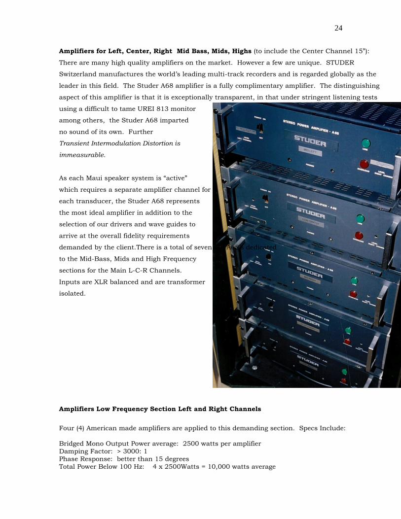
Amplifiers for Left, Center, Right Mid Bass, Mids, Highs (to include the Center Channel 15”):
There are many high quality amplifiers on the market. However a few are unique. STUDER
Switzerland manufactures the world’s leading multi-track recorders and is regarded globally as the
leader in this field. The Studer A68 amplifier is a fully complimentary amplifier. The distinguishing
aspect of this amplifier is that it is exceptionally transparent, in that under stringent listening tests
using a difficult to tame UREI 813 monitor
among others, the Studer A68 imparted
no sound of its own. Further
Transient Intermodulation Distortion is
immeasurable.
As each Maui speaker system is “active”
which requires a separate amplifier channel for
each transducer, the Studer A68 represents
the most ideal amplifier in addition to the
selection of our drivers and wave guides to
arrive at the overall fidelity requirements
demanded by the client.There is a total of seven (7) A68’s dedicated
to the Mid-Bass, Mids and High Frequency
sections for the Main L-C-R Channels.
Inputs are XLR balanced and are transformer
isolated.
Amplifiers Low Frequency Section Left and Right Channels
Four (4) American made amplifiers are applied to this demanding section. Specs Include:
Bridged Mono Output Power average: 2500 watts per amplifier
Damping Factor: > 3000: 1 Phase Response: better than 15 degrees
Total Power Below 100 Hz: 4 x 2500Watts = 10,000 watts average

25
Amplifiers for Bi-amplified Surround Channels:
The six surround channels require 12 channels of amplification.
Bruce had an existing UREI 6290 amplifier which was removed from a previous studio.
This great amplifier (62 pounds / 29 Kgs) produces over 400 watts per channel average
This was the ideal amplifier to be applied to the six (6) 15 inch woofers which are identical to the
Center Channel 15 inch woofer.
3 each UREI 6290 amplifiers in 2 channel mode (6 channels total) are applied below 1600 Hz for a
total of 2400 watts average power. Leader provided two new amplifiers for a total of 3 units.
The High Frequency Section also requires 6 channels of amplification. A single Miles Audio 6
channel amplifier @ 125 watts per channel with Darlington Pair output stages drives the Mid-Hi
section above 1600 Hz.
The entire surround array out performs most cinemas Main Screen Channels. The overall fidelity is
exceptional. The low frequency section together with the mid band wave guides and driver has
identical sound characteristics to the center and left & right channels. The acoustical match
between the front and side/surround channels results in a seamless transition as effects pass
between side and front locations. The HF response is tailored and does not use the traditional “X”
curve. We at Leader Cinema find the X curve when applied to the Surround Channels to be
incorrect, as sound arriving at the ear from the sides has a completely different character than from
the front, where the X curve was originally derived (after Schulein AES Paper). Leader does apply
surround channel equalization which more accurately matches with the Main Screen Channels.
The maximum SPL performance from the full Surround Channel array is: 127 dB SPL
The average sustained long term output in Acoustic Watts: 117 a Watts (not electrical amplifier watts)
Low Frequency Power Bandwidth: 27 Hz – 3dB
Audience area receives Quasi Constant Power (rather than constant intensity in the case of
traditional cinema surround channel speaker positions) which results in a more open and

26
immersive sound field. The audience positioned inside an LHF(tm) surround array does not zero-in
on a speaker location or group of speakers.
Low Frequency Re-capture is applied to extract low frequencies from the sound track which has
been reduced in level below 85 Hz (hi passed at 85 Hz) during the dubbing process. This is done to
protect all surround speakers (read underpowered at low frequencies otherwise limited “power
response”) and this has been common since the development of THX(tm) systems commencing in
1983 and is still a problem today in the mid 1990’s!! across the entire public cinema exhibition
industry.
The Leader LF Recapture(tm) process extends the Surround Low frequency performance down to a
solid 30 Hz or lower depending upon the sound effect. The motion pictures Jumanji and Hunt for
Red October are both ideal examples where the Dubbing Stage Mixers have introduced greater
amounts of low frequency information into the surround channels, (see Kintek data). Unfortunately
most cinemas are unable to reproduce these dramatic LF effects...but the info is there on the
completed sound track although at a greatly reduced level.
AC POWER
All great edifices require a solid foundation. In terms of high performance studio systems the power
and grounding system is the equivalent of the rocket fuel to power this time machine. This being a
complex residence where the residence long axis runs along the length of the property, the distance
from the street power drop to the house spans 100 feet. The main distro panel and breaker box is
located in the garage, about 30 feet from the street and 75 feet to the auxiliary breaker panels within
the house proper. As we require a technical power and grounding system, commonly referred to as
an IG (Isolated Ground System) or simply Tech Power, such systems are to be found in recording
facilities, post production studios, radio broadcast and television stations.
The overall 100 foot run from the street to the house would result in challenges for us. The
residence contains a large machine room to run the pool pumps and zero infinity edge pool spill way
motors. Multiple HVAC systems, refrigerators and vacuum cleaners all create various forms of
electrical “clicks, pops and whines” as various devices are turned on or off. Some of course better
than others. However, there is no absolute guarantee that the Neutral would remain at zero volts
when various devices are used. This also would impact upon the noise and voltage performance
required to satisfy the wide dynamic range capabilities for the entire sound and video system(s) for
both the Living Room and Music Studio.

27
With much heated debate with the electrical contractor, local electrical inspectors, Maui Electric and
a local consultant, Leader Cinema won. Located in the garage was a dedicated 4 wire panel with
Isolated Ground System. Feeds to this panel were derived from the lowest “stud” feeding the main
panel from the street. This represented the lowest impedance and hence the best possible possibility
of eliminating any noise on both the Neutral and Ground conductors.
The 85 foot run from the garage to the house took a slightly different path from the main feed. This
was to prevent any induced noise into the Tech Power system from the Main House feed had they
been run in close proximity. The sub-breaker panel in the house provided clean power to both the
Music Studio and Living Room technical racks which included the 220 volts for the projector.
Upon completion of the system, we demonstrated the superiority of this technique to the electrical
contractor and to Maui Electric. In a highly un-ethical temporary patch, we swapped out the “clean
feed” and substituted the Main House feed into our Tech Power Sub-Panel. With the sound systems
gain at full in addition to an additional +10 dB of gain, using the IG Tech Power System, the audio
(very low level) quiescent noise remained constant as motors, pumps, refrigerators & freezers and
vacuum cleaners were cycled on and off.
However, when the system was operated on House Power, clicks, pops motor whine was clearly
audible. Reducing the system gain to “normal” and removing the optional +10 dB gain, background
noise during the cycling of motors and pumps clearly could be heard, although at much lower
volume.....yes due to the overall volume being turned down. When playing music at a low level,
some background noises were still discernable, but became masked when music was played at a
healthy level. Both the electrical contractor and Maui Electric were surprised with the results of this
dramatic demonstration.
Back on Tech Power, even with elevated gain of +10 dB, placing ones head next to a speaker system,
no noise or hum at all can be heard. (you had better stand back before someone presses the “play”
button!)
In Conclusion:
The overall project spanned 6 years from the time we were first introduced to Dunbar and through to
completion. Much of the preliminary design work we had achieved prior to 1991. However, the
28
magic behind the success again was a motivated client who knew exactly what they wanted together
with the architectural team who embraced the exceptional and esoteric professional needs of their
client. The relationship between Leader and Erickson really was the magic sauce behind the
success. Without the physical aspects being created and modified to meet our technical
requirements, the electro-acoustic outcome might have been completely different.
The results were just as Leader had expected them to be when we had the test system in operation
in our 1200 sq ft well damped development theater in Vancouver during 1993. It was wow then, and
w-o-w upon completion smack dap in the middle of the Pacific Ocean..... Wowee on Maui !
*END*
The Studio System is covered in Part 2
29
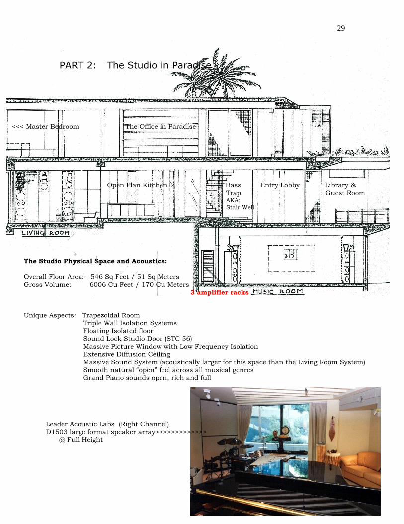
PART 2: The Studio in Paradise
<<< Master Bedroom The Office in Paradise
Open Plan Kitchen Bass Entry Lobby Library &
Trap Guest Room AKA: Stair Well
The Studio Physical Space and Acoustics:
Overall Floor Area: 546 Sq Feet / 51 Sq Meters
Gross Volume: 6006 Cu Feet / 170 Cu Meters
3 amplifier racks
Unique Aspects: Trapezoidal Room
Triple Wall Isolation Systems
Floating Isolated floor
Sound Lock Studio Door (STC 56)
Massive Picture Window with Low Frequency Isolation Extensive Diffusion Ceiling
Massive Sound System (acoustically larger for this space than the Living Room System)
Smooth natural “open” feel across all musical genres
Grand Piano sounds open, rich and full
Leader Acoustic Labs (Right Channel)
D1503 large format speaker array>>>>>>>>>>>>> @ Full Height

30
3 racks Electronics
<<<<<<D1503 Center D1503>>>>>
The studio is a fully isolated “floating” enclosure. Triple wall construction together with “jack up”
poured concrete floor, isolated ceiling and a massive multi-layered window system (designed by
Leader) results in a fully “sound proofed” room. The HVAC system is an in floor system, with the
warm air returns located above the equipment racks. The ceiling system inside the studio is a
“diffusion” ceiling which contributes to the expansive nature of this medium sized room. This ceiling
system eliminates specular reflections. The diffused energy is reduced in amplitude and is spread
out in time. This energy which is spread out in time falls approximating an exponential value. This
technique was chosen over an absorptive ceiling (such as in the Living Room) as the acoustical
signature of the room would have become dull. The room upon entering has an intimate appeal due
to the overall design and color scheme together with natural daylight.
At right, one of three racks of electronics. Illustrated here is Rack 1 which contains 80% of the amplifiers for the Living Room
System.
Left, Rack 2 (Signal Processing) in service position.
Rack 3: contains additional amplifiers for Living Room and Studio System. Rack 3 located to left
of closet door. None of the equipment contains any user controls, execpt Rack 2.

31
The Sound System:
Two (2) Leader Hollywood Format(tm) D1503 tri-amplified systems were custom manufactured to
meet the requirements for this trapezoidal shaped room. The Mid-Hi wave guides were modified to
provide slightly less than 90 degree Horizontal dispersion. This was a requirement, as the side walls
fold inwards, which reduces the width of the room at the “back” wall, illustrated with the sofa in the
picture. Upon completion, the stereo imaging exhibits pin-point accuracy together with fidelity again
which meets the subjective requirements established by Mr. Dunbar 5 years earlier. The mid-hi
smoothness indeed mimics the performance of his beloved Sennheiser headphones, while the depth
of the extended bass musically speaking takes on the weight and spatial dimensions of true to life
“on stage” musical experiences. This is true across bass lines experienced in classical works, to jazz,
chamber music (cellos are masterful) to include the driving force of rock, hip-hop, R&B and pop
music. This sound system also doubles as a “live performance sound system”. Drum pads, and
keyboards are reproduced via this system. While this room is smaller than the Living Room, this
sound system is actually larger than the Living Room system.
The headroom requirements for this system, are such that, while a smaller system could have been
incorporated to play back recorded music to an exceptionally high studio standard, it was necessary
due to live “un-processed” sound sources to have a system that would withstand the occasional
accidental blast of sound through operational error, such as a dropped microphone, feedback, or a
volume control positioned at “11” on a keyboard.
The max sound pressure levels capable from each of the D1503 sections (prior to final system
balance) in the middle of the room are:
Low Frequencies 26 Hz to 85 Hz: 126 dB SPL (average long term)
(includes acoustical gain due to trihedral mounting position of the enclosure in 1/8 space)
@ 1200 watts / 76 volts (10 millisecond peaks = 4800 watts / 152 volts) for each enclosure
Mid frequencies: 80 Hz to 2000 Hz: 130 dB SPL @ 1 meter or 122 dB SPL to middle of room
Hi-Frequencies (25% efficiency): 128 dB SPL @ 1 meter / or 120.8 dB SPL to middle of room
The resulting final calibrated performance for one D1503 results in a continuous SPL of: 124 dB
SPL average, with safe peaks extending to 132 dB SPL. Limiters are incorporated into the signal
processing chain to protect the system above 124 dB SPL.
Each D1503 has an overall total enclosure weight of approximately: 760 pounds / 345 Kgs

32
Amplifiers: Total Power for Left and Right Channels: 8380 Watts Average
Low Frequencies: Two Crown Macro Tech 3600 VZ Amplifiers, Bridged Mono @ 3140 watts each
Mid Frequencies: Two STUDER A 68 Amplifiers bridged mono
Hi-Frequencies: One STUDER A 68 Amplifier, two channel mode
Crossover Networks: Linkwitz-Riley 24 dB / Octave with time delays / Balanced XLR / peak output level per section = + 28 dBm (note: “m”)
Hum and noise: System gain “nominal operating level” to achieve 118 dB SPL, hum and noise
is completely inaudible at the speaker enclosure
Center Channel: Due to space limitations, a modified version of the living rooms Center Channel was incorporated into the music studio. The resulting monitor
system is a two way, bi-amplified enclosure. It uses the identical mid-hi wave
guide that we developed for both the Living Room Surround Channels which
also was used in the Center Channel. There not being sufficient space for a 7
cu foot speaker enclosure to contain a 15 inch woofer, Leader Acoustic Labs modified a 12 inch woofer and incorporated a Cetec Gauss magnetic system
and voice coil from a mid bass 15 inch studio woofer. The 400 watt power
handling of our 12 inch “special” woofer resulted in an enclosure of 5 cu feet.
The results again are nothing short of stellar from a small enclosure with
musical clarity and velvet smoothness.
Amplifier: STUDER A68, two channel mode
CH 1 = Low Frequencies
CH 2 = Hi Frequencies
Surround Channels: Concealed from view behind acoustically transparent bulkhead are two (2) Electro-Voice Sentry 100A studio monitors.
Digital “Surround Sound” Processor: DOLBY LABS DP 562 (same device as Living
Room System)
Projection Systems: Two projectors are co-located within the acoustically transparent bulkhead. PJ 1 provides hi quality video projection
PJ 2 provides data from various instruments
Studio Sound Lock Doors: Custom made to Leader specifications by Acoustical Solutions, Inc
Door System designed to: STC 56
Studio Picture Window: Designed by M. Leader / Leader Acoustic Labs and manufactured by
Advanced Glazing Systems, Inc Seattle / Vancouver
Signal Path, Levels and Routing: Part 3
(C) 1997

33
The Master Bedroom in Paradise (with Leader/Dolby Digital Surround..of course)
Related Documents