RR.Road,CristobalSt.,Paco,Manila www.ps-philgeps.gov.ph 8 290-6300 / 8 290-6400 Republic of the Philippines Department of Budget and M PROCUREMENT SERVI PHILIPPINE GOVERNM BIDS AND AWARDS COM THE MALOLOS-CLARK PROJECT SOUTH LIN ELECTRICAL AND MECHA TO ALL PROSPECTIVE BID This General Bid Bulletin is iss for the above-mentioned Proje Bulletin for details: 1. Annex “A” - Clari 2. Annex “B” - Adde 3. Annex “C” - Not A All other portions of the Biddin and/or clarifications shall rem Revisions/amendments/clarific Bidding Documents of this Pro For your guidance and inform DBM Compound, Gen www.philgeps.gov.ph (02) 8 640 6906 | 8 64 Management ICE - MENT ELECTRONIC PROCUREMENT SYSTEM MMITTEE General Bid Bulletin No. 24 31 August 2021 RAILWAY PROJECT AND THE NORTH-S NE COMMUTER PACKAGE CP NS-01: PRO ANICAL SYSTEMS AND TRACK WORKS ( DDERS: sued to amend/clarify certain provisions in th ect. Please refer to the attached Annexes of ification to the Bidding Documents endum to the Bidding Documents with “Atta Applicable ng Documents not affected by these revision main unchanged. cations made herein shall be conserved as an oject. mation. For the Bids and Awa ENGR. JAIME M. NA Chairpers neral Solano Street, San Miguel, Manila 40 6907 | 8 640 6908 | 8 640 6909 M SOUTH RAILWAY OCUREMENT OF (IFB No: 21-040-3) he Bidding Documents this General Bid achment 1” ns, amendments n integral part of the ards Committee AVARRETE, JR son SIGNATURE REDACTED

Welcome message from author
This document is posted to help you gain knowledge. Please leave a comment to let me know what you think about it! Share it to your friends and learn new things together.
Transcript
RR.Road,CristobalSt.,Paco,Manila www.ps-philgeps.gov.ph 8 290-6300 / 8 290-6400
Republic of the Philippines Department of Budget and ManagementPROCUREMENT SERVICE PHILIPPINE GOVERNMENT ELECTRONIC PROCUREMENT SYSTEMBIDS AND AWARDS COMMITTEE
THE MALOLOS-CLARK RAILWAY PROJECT AND THE NORTHPROJECT SOUTH LINE COMMUTER PACKAGE CP NS
ELECTRICAL AND MECHANICAL SYSTEMS AND TRACK WORKS
TO ALL PROSPECTIVE BIDDERS: This General Bid Bulletin is issufor the above-mentioned Project. Please refer to the attached Annexes of this General Bid Bulletin for details:
1. Annex “A” - Clarification to the Bidding Documents2. Annex “B” - Addendum to the Bidding Documents with “3. Annex “C” - Not Applicable
All other portions of the Bidding Documents not affected by these revisions, amendments and/or clarifications shall remain unchanged. Revisions/amendments/clarifications Bidding Documents of this Project. For your guidance and information.
DBM Compound, General Solano Street, www.philgeps.gov.ph (02) 8 640 6906 | 8 640 6907 | 8 640 6908 | 8 640 6909
Department of Budget and Management PROCUREMENT SERVICE - PHILIPPINE GOVERNMENT ELECTRONIC PROCUREMENT SYSTEMBIDS AND AWARDS COMMITTEE
General Bid Bulletin No. 24
31 August 2021
CLARK RAILWAY PROJECT AND THE NORTH-SOUTH RAILWAY PROJECT SOUTH LINE COMMUTER PACKAGE CP NS-01: PROCUREMENT OF
ELECTRICAL AND MECHANICAL SYSTEMS AND TRACK WORKS (IFB No: 21
TO ALL PROSPECTIVE BIDDERS:
This General Bid Bulletin is issued to amend/clarify certain provisions in the Bidding Documents mentioned Project. Please refer to the attached Annexes of this General Bid
Clarification to the Bidding Documents Addendum to the Bidding Documents with “Attachment 1Not Applicable
All other portions of the Bidding Documents not affected by these revisions, amendments and/or clarifications shall remain unchanged.
Revisions/amendments/clarifications made herein shall be conserved as an integral part of the Bidding Documents of this Project.
For your guidance and information.
For the Bids and Awards Committee
ENGR. JAIME M. NAVARRETE, JR Chairperson
DBM Compound, General Solano Street, San Miguel, Manila
(02) 8 640 6906 | 8 640 6907 | 8 640 6908 | 8 640 6909
PHILIPPINE GOVERNMENT ELECTRONIC PROCUREMENT SYSTEM
SOUTH RAILWAY 01: PROCUREMENT OF
(IFB No: 21-040-3)
ed to amend/clarify certain provisions in the Bidding Documents mentioned Project. Please refer to the attached Annexes of this General Bid
Attachment 1”
All other portions of the Bidding Documents not affected by these revisions, amendments
made herein shall be conserved as an integral part of the
For the Bids and Awards Committee
ENGR. JAIME M. NAVARRETE, JR Chairperson
SIGNATURE REDACTED
PDFescape
Highlight

Annex A
Page 1 of 19
PACKAGE CP NS-01: E&M SYSTEMS AND TRACK WORKS
General Bid Bulletin No. 24 Annex A
Item No.
Volume Section No. Page No.
Clause No. / Title Reference Text
Clarification Request Proposed Revised
Text (if any)
Response
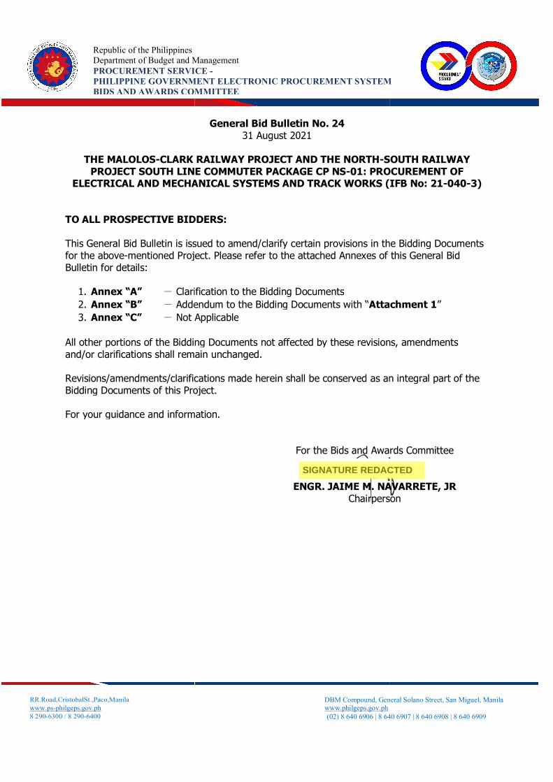
1 Part 2 – Employer’s Requirements Section V1. Employer’s Requirements General Requirements , 91, Clause 11.2.6, All replacement and repairs under the Defect Notification Period shall be carried out by the Contractor promptly and completed to satisfaction of the Engineer, on notification of the defect by the Employer and/or the Engineer on behalf of the Employer so that no Railway System equipment is unfit for service for more than twenty-four (24) hours or another period the Engineer may agree to, which shall exclude the time taken for withdrawal/ induction of trains from/to services
Kindly confirm that the Employer’s Operator will proceed with the dismounting, replacement and configuration of defective material on site/on trains (corrective maintenance), and the Contractor shall provide supervision to these activities, as well as the shipment and repair of said defective material, as part of the DNP obligations.
Corrective maintenance action will be undertaken by the Employer’s Operator supported by the E&M Contractor. Removal and shipment of defected materials, provision of new material and root-cause analysis and all associated costs shall be borne by the Contractor. Replaced parts shall be investigated and replaced or repaired by the E&M Contractor free of cost.
2 Part 2 Section VI, 619, 7.2.1.2 Limited Express Ticket System, The AFC system shall cover the Limited
We assume that the Limited Express Train Service will connect the Metro Manila and Clark International Airport with stops at Alabang and
Please refer to GBB16 Annex A Item 2
Page 2 of 19
PACKAGE CP NS-01: E&M SYSTEMS AND TRACK WORKS General Bid Bulletin No. 24
Annex A Item No.
Volume Section No. Page No.
Clause No. / Title Reference Text
Clarification Request Proposed Revised
Text (if any)
Response
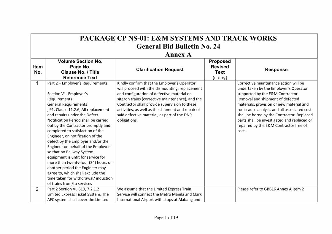
Express Service however unlike the commuter services, the passengers for Limited Express shall be required to validate their SJT and SVC prior to boarding. Ticket validator shall be mounted on Limited Express Platform Screen doors, or any other location proposed by the Contractor, and approved by the Engineer. This validator will ensure that SJT’s are valid tickets being used on the Limited Express whilst in the case of SVC’s the validator will deduct the fare for taking the Limited Express service.
Buendia. As per RFP specification, the passengers for Limited Express shall be required to validate their SJT and SVC at the mounted validators on platform screen doors prior to boarding for the specified stops at CIA, Alabang and Buendia under Limited Express Train Service. In consideration of the operational requirement, does the Contractor need to supply and install the physical automatic gate for entry and exit purpose? Please confirm.
3 Part 2 Section VI, 619, 7.2.1.3 Limited Express Ticket System, The system performance shall conform to the AFC National Standard
Please kindly provide the definition of the "AFC National Standard".
Please refer to GBB16 Annex A Item 3
4 Part 2 Section VI, 637, 7.7.9.1 QR Code Payment, The AFC system shall include a QR code payment system. The QR code system provisions shall include, but shall not be limited to,
Under the RFP document, the Contractor cannot find where the paper QR code tickets will be physically generated from. Does the TVM or POS need to generate the paper QR
Please refer to GBB16 Annex A Item 5
Page 3 of 19
PACKAGE CP NS-01: E&M SYSTEMS AND TRACK WORKS General Bid Bulletin No. 24
Annex A Item No.
Volume Section No. Page No.
Clause No. / Title Reference Text
Clarification Request Proposed Revised
Text (if any)
Response
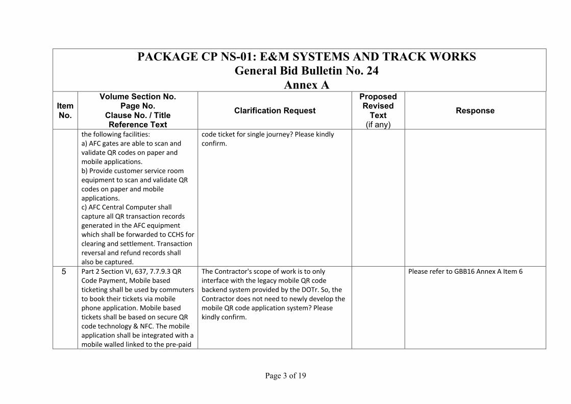
the following facilities: a) AFC gates are able to scan and validate QR codes on paper and mobile applications. b) Provide customer service room equipment to scan and validate QR codes on paper and mobile applications. c) AFC Central Computer shall capture all QR transaction records generated in the AFC equipment which shall be forwarded to CCHS for clearing and settlement. Transaction reversal and refund records shall also be captured.
code ticket for single journey? Please kindly confirm.
5 Part 2 Section VI, 637, 7.7.9.3 QR Code Payment, Mobile based ticketing shall be used by commuters to book their tickets via mobile phone application. Mobile based tickets shall be based on secure QR code technology & NFC. The mobile application shall be integrated with a mobile walled linked to the pre-paid
The Contractor's scope of work is to only interface with the legacy mobile QR code backend system provided by the DOTr. So, the Contractor does not need to newly develop the mobile QR code application system? Please kindly confirm.
Please refer to GBB16 Annex A Item 6
Page 4 of 19
PACKAGE CP NS-01: E&M SYSTEMS AND TRACK WORKS General Bid Bulletin No. 24
Annex A Item No.
Volume Section No. Page No.
Clause No. / Title Reference Text
Clarification Request Proposed Revised
Text (if any)
Response
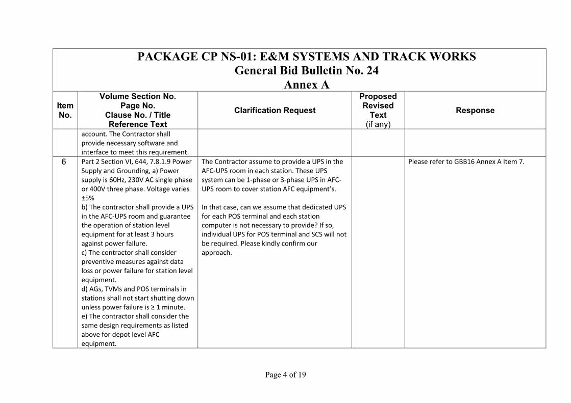
account. The Contractor shall provide necessary software and interface to meet this requirement.
6 Part 2 Section VI, 644, 7.8.1.9 Power Supply and Grounding, a) Power supply is 60Hz, 230V AC single phase or 400V three phase. Voltage varies ±5% b) The contractor shall provide a UPS in the AFC-UPS room and guarantee the operation of station level equipment for at least 3 hours against power failure. c) The contractor shall consider preventive measures against data loss or power failure for station level equipment. d) AGs, TVMs and POS terminals in stations shall not start shutting down unless power failure is ≥ 1 minute. e) The contractor shall consider the same design requirements as listed above for depot level AFC equipment.
The Contractor assume to provide a UPS in the AFC-UPS room in each station. These UPS system can be 1-phase or 3-phase UPS in AFC-UPS room to cover station AFC equipment’s. In that case, can we assume that dedicated UPS for each POS terminal and each station computer is not necessary to provide? If so, individual UPS for POS terminal and SCS will not be required. Please kindly confirm our approach.
Please refer to GBB16 Annex A Item 7.
Page 5 of 19
PACKAGE CP NS-01: E&M SYSTEMS AND TRACK WORKS General Bid Bulletin No. 24
Annex A Item No.
Volume Section No. Page No.
Clause No. / Title Reference Text
Clarification Request Proposed Revised
Text (if any)
Response
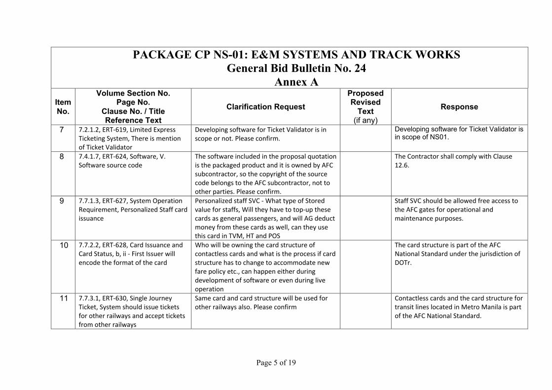
7 7.2.1.2, ERT-619, Limited Express Ticketing System, There is mention of Ticket Validator
Developing software for Ticket Validator is in scope or not. Please confirm.
Developing software for Ticket Validator is in scope of NS01.
8 7.4.1.7, ERT-624, Software, V. Software source code
The software included in the proposal quotation is the packaged product and it is owned by AFC subcontractor, so the copyright of the source code belongs to the AFC subcontractor, not to other parties. Please confirm.
The Contractor shall comply with Clause 12.6.
9 7.7.1.3, ERT-627, System Operation Requirement, Personalized Staff card issuance
Personalized staff SVC - What type of Stored value for staffs, Will they have to top-up these cards as general passengers, and will AG deduct money from these cards as well, can they use this card in TVM, HT and POS
Staff SVC should be allowed free access to the AFC gates for operational and maintenance purposes.
10 7.7.2.2, ERT-628, Card Issuance and Card Status, b, ii - First Issuer will encode the format of the card
Who will be owning the card structure of contactless cards and what is the process if card structure has to change to accommodate new fare policy etc., can happen either during development of software or even during live operation
The card structure is part of the AFC National Standard under the jurisdiction of DOTr.
11 7.7.3.1, ERT-630, Single Journey Ticket, System should issue tickets for other railways and accept tickets from other railways
Same card and card structure will be used for other railways also. Please confirm
Contactless cards and the card structure for transit lines located in Metro Manila is part of the AFC National Standard.
Page 6 of 19
PACKAGE CP NS-01: E&M SYSTEMS AND TRACK WORKS General Bid Bulletin No. 24
Annex A Item No.
Volume Section No. Page No.
Clause No. / Title Reference Text
Clarification Request Proposed Revised
Text (if any)
Response
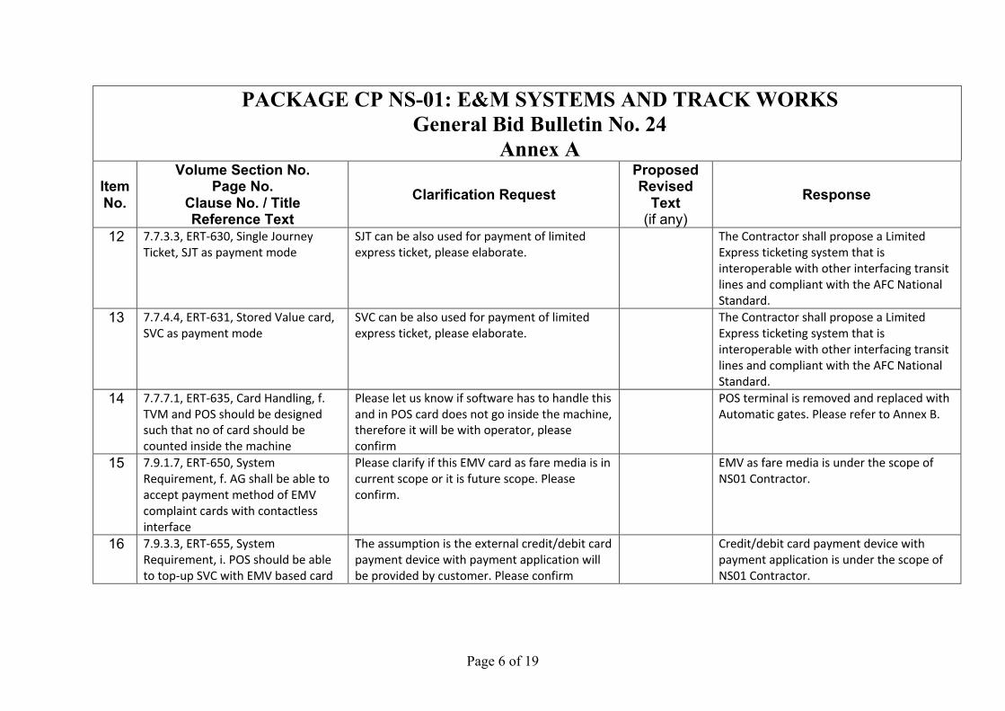
12 7.7.3.3, ERT-630, Single Journey Ticket, SJT as payment mode
SJT can be also used for payment of limited express ticket, please elaborate.
The Contractor shall propose a Limited Express ticketing system that is interoperable with other interfacing transit lines and compliant with the AFC National Standard.
13 7.7.4.4, ERT-631, Stored Value card, SVC as payment mode
SVC can be also used for payment of limited express ticket, please elaborate.
The Contractor shall propose a Limited Express ticketing system that is interoperable with other interfacing transit lines and compliant with the AFC National Standard.
14 7.7.7.1, ERT-635, Card Handling, f. TVM and POS should be designed such that no of card should be counted inside the machine
Please let us know if software has to handle this and in POS card does not go inside the machine, therefore it will be with operator, please confirm
POS terminal is removed and replaced with Automatic gates. Please refer to Annex B.
15 7.9.1.7, ERT-650, System Requirement, f. AG shall be able to accept payment method of EMV complaint cards with contactless interface
Please clarify if this EMV card as fare media is in current scope or it is future scope. Please confirm.
EMV as fare media is under the scope of NS01 Contractor.
16 7.9.3.3, ERT-655, System Requirement, i. POS should be able to top-up SVC with EMV based card
The assumption is the external credit/debit card payment device with payment application will be provided by customer. Please confirm
Credit/debit card payment device with payment application is under the scope of NS01 Contractor.
Page 7 of 19
PACKAGE CP NS-01: E&M SYSTEMS AND TRACK WORKS General Bid Bulletin No. 24
Annex A Item No.
Volume Section No. Page No.
Clause No. / Title Reference Text
Clarification Request Proposed Revised
Text (if any)
Response
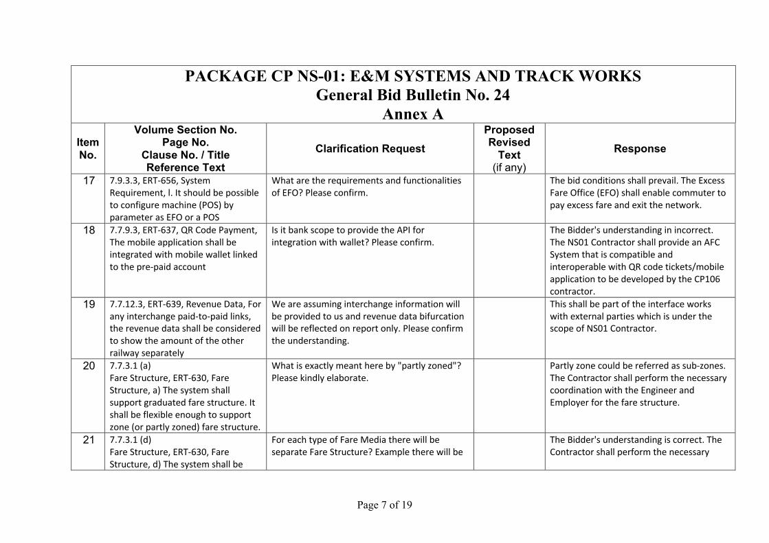
17 7.9.3.3, ERT-656, System Requirement, l. It should be possible to configure machine (POS) by parameter as EFO or a POS
What are the requirements and functionalities of EFO? Please confirm.
The bid conditions shall prevail. The Excess Fare Office (EFO) shall enable commuter to pay excess fare and exit the network.
18 7.7.9.3, ERT-637, QR Code Payment, The mobile application shall be integrated with mobile wallet linked to the pre-paid account
Is it bank scope to provide the API for integration with wallet? Please confirm.
The Bidder's understanding in incorrect. The NS01 Contractor shall provide an AFC System that is compatible and interoperable with QR code tickets/mobile application to be developed by the CP106 contractor.
19 7.7.12.3, ERT-639, Revenue Data, For any interchange paid-to-paid links, the revenue data shall be considered to show the amount of the other railway separately
We are assuming interchange information will be provided to us and revenue data bifurcation will be reflected on report only. Please confirm the understanding.
This shall be part of the interface works with external parties which is under the scope of NS01 Contractor.
20 7.7.3.1 (a) Fare Structure, ERT-630, Fare Structure, a) The system shall support graduated fare structure. It shall be flexible enough to support zone (or partly zoned) fare structure.
What is exactly meant here by "partly zoned"? Please kindly elaborate.
Partly zone could be referred as sub-zones. The Contractor shall perform the necessary coordination with the Engineer and Employer for the fare structure.
21 7.7.3.1 (d) Fare Structure, ERT-630, Fare Structure, d) The system shall be
For each type of Fare Media there will be separate Fare Structure? Example there will be
The Bidder's understanding is correct. The Contractor shall perform the necessary
Page 8 of 19
PACKAGE CP NS-01: E&M SYSTEMS AND TRACK WORKS General Bid Bulletin No. 24
Annex A Item No.
Volume Section No. Page No.
Clause No. / Title Reference Text
Clarification Request Proposed Revised
Text (if any)
Response
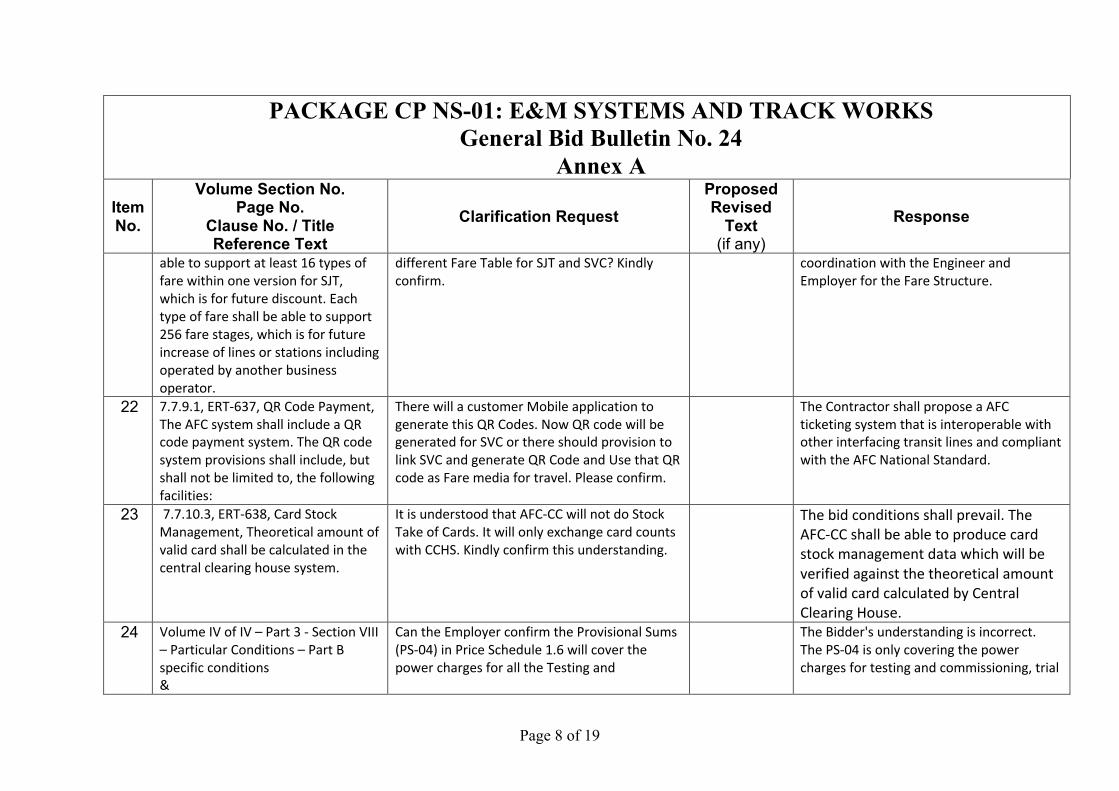
able to support at least 16 types of fare within one version for SJT, which is for future discount. Each type of fare shall be able to support 256 fare stages, which is for future increase of lines or stations including operated by another business operator.
different Fare Table for SJT and SVC? Kindly confirm.
coordination with the Engineer and Employer for the Fare Structure.
22 7.7.9.1, ERT-637, QR Code Payment, The AFC system shall include a QR code payment system. The QR code system provisions shall include, but shall not be limited to, the following facilities:
There will a customer Mobile application to generate this QR Codes. Now QR code will be generated for SVC or there should provision to link SVC and generate QR Code and Use that QR code as Fare media for travel. Please confirm.
The Contractor shall propose a AFC ticketing system that is interoperable with other interfacing transit lines and compliant with the AFC National Standard.
23 7.7.10.3, ERT-638, Card Stock Management, Theoretical amount of valid card shall be calculated in the central clearing house system.
It is understood that AFC-CC will not do Stock Take of Cards. It will only exchange card counts with CCHS. Kindly confirm this understanding.
The bid conditions shall prevail. The AFC-CC shall be able to produce card stock management data which will be verified against the theoretical amount of valid card calculated by Central Clearing House.
24 Volume IV of IV – Part 3 - Section VIII – Particular Conditions – Part B specific conditions &
Can the Employer confirm the Provisional Sums (PS-04) in Price Schedule 1.6 will cover the power charges for all the Testing and
The Bidder's understanding is incorrect. The PS-04 is only covering the power charges for testing and commissioning, trial
Page 9 of 19
PACKAGE CP NS-01: E&M SYSTEMS AND TRACK WORKS General Bid Bulletin No. 24
Annex A Item No.
Volume Section No. Page No.
Clause No. / Title Reference Text
Clarification Request Proposed Revised
Text (if any)
Response
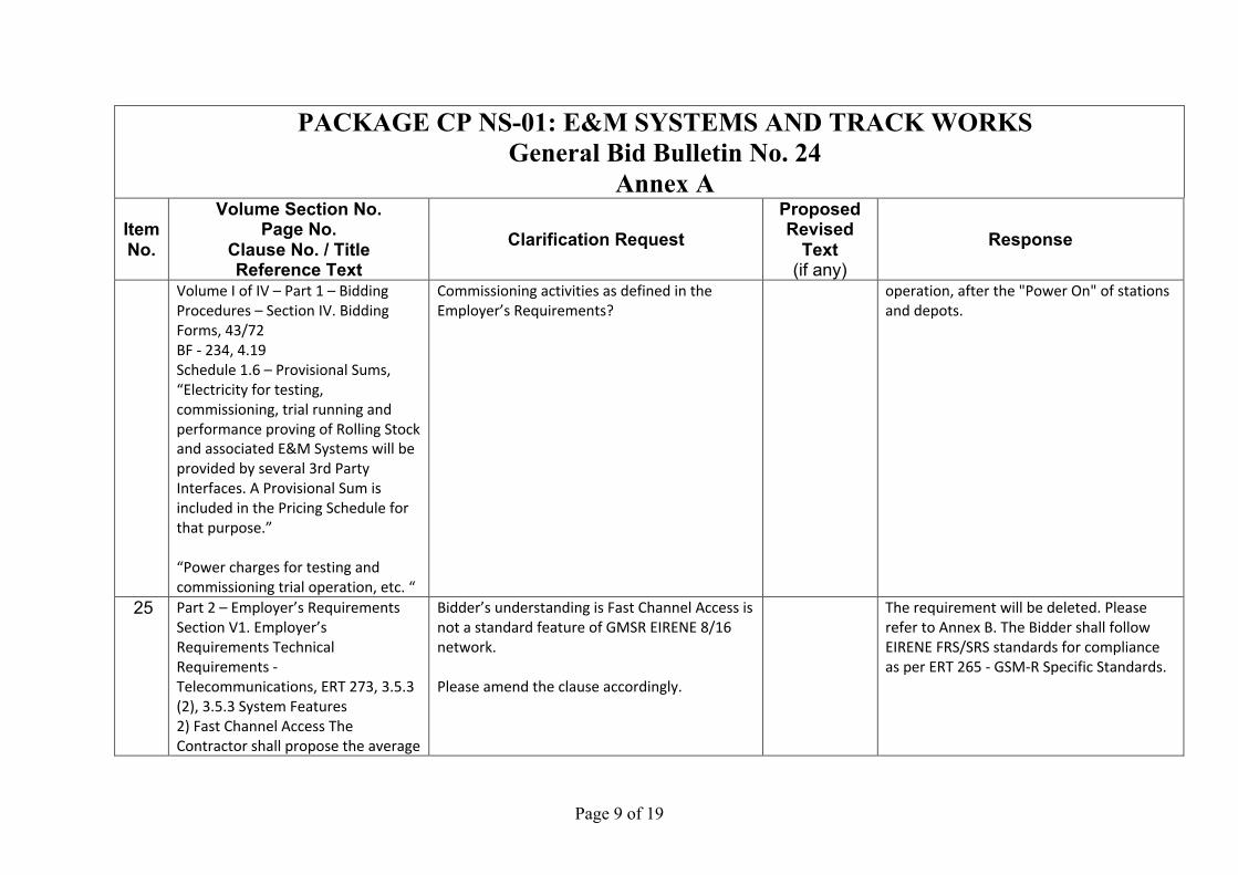
Volume I of IV – Part 1 – Bidding Procedures – Section IV. Bidding Forms, 43/72 BF - 234, 4.19 Schedule 1.6 – Provisional Sums, “Electricity for testing, commissioning, trial running and performance proving of Rolling Stock and associated E&M Systems will be provided by several 3rd Party Interfaces. A Provisional Sum is included in the Pricing Schedule for that purpose.” “Power charges for testing and commissioning trial operation, etc. “
Commissioning activities as defined in the Employer’s Requirements?
operation, after the "Power On" of stations and depots.
25 Part 2 – Employer’s Requirements Section V1. Employer’s Requirements Technical Requirements - Telecommunications, ERT 273, 3.5.3 (2), 3.5.3 System Features 2) Fast Channel Access The Contractor shall propose the average
Bidder’s understanding is Fast Channel Access is not a standard feature of GMSR EIRENE 8/16 network. Please amend the clause accordingly.
The requirement will be deleted. Please refer to Annex B. The Bidder shall follow EIRENE FRS/SRS standards for compliance as per ERT 265 - GSM-R Specific Standards.
Page 10 of 19
PACKAGE CP NS-01: E&M SYSTEMS AND TRACK WORKS General Bid Bulletin No. 24
Annex A Item No.
Volume Section No. Page No.
Clause No. / Title Reference Text
Clarification Request Proposed Revised
Text (if any)
Response
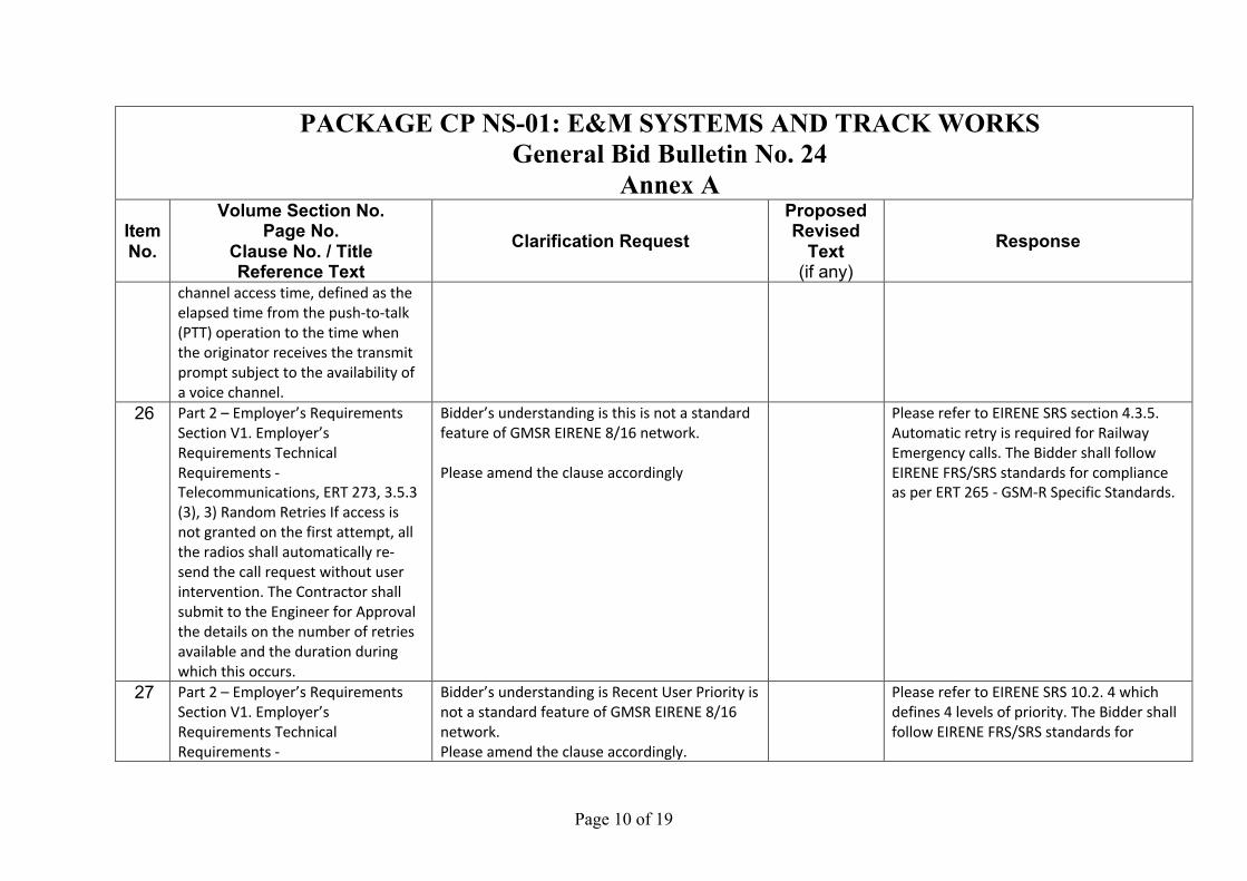
channel access time, defined as the elapsed time from the push-to-talk (PTT) operation to the time when the originator receives the transmit prompt subject to the availability of a voice channel.
26 Part 2 – Employer’s Requirements Section V1. Employer’s Requirements Technical Requirements - Telecommunications, ERT 273, 3.5.3 (3), 3) Random Retries If access is not granted on the first attempt, all the radios shall automatically re-send the call request without user intervention. The Contractor shall submit to the Engineer for Approval the details on the number of retries available and the duration during which this occurs.
Bidder’s understanding is this is not a standard feature of GMSR EIRENE 8/16 network. Please amend the clause accordingly
Please refer to EIRENE SRS section 4.3.5. Automatic retry is required for Railway Emergency calls. The Bidder shall follow EIRENE FRS/SRS standards for compliance as per ERT 265 - GSM-R Specific Standards.
27 Part 2 – Employer’s Requirements Section V1. Employer’s Requirements Technical Requirements -
Bidder’s understanding is Recent User Priority is not a standard feature of GMSR EIRENE 8/16 network. Please amend the clause accordingly.
Please refer to EIRENE SRS 10.2. 4 which defines 4 levels of priority. The Bidder shall follow EIRENE FRS/SRS standards for
Page 11 of 19
PACKAGE CP NS-01: E&M SYSTEMS AND TRACK WORKS General Bid Bulletin No. 24
Annex A Item No.
Volume Section No. Page No.
Clause No. / Title Reference Text
Clarification Request Proposed Revised
Text (if any)
Response
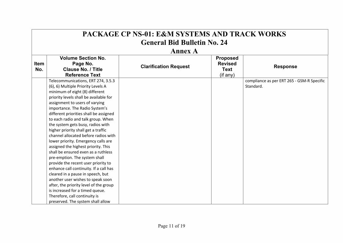
Telecommunications, ERT 274, 3.5.3 (6), 6) Multiple Priority Levels A minimum of eight (8) different priority levels shall be available for assignment to users of varying importance. The Radio System’s different priorities shall be assigned to each radio and talk group. When the system gets busy, radios with higher priority shall get a traffic channel allocated before radios with lower priority. Emergency calls are assigned the highest priority. This shall be ensured even as a ruthless pre-emption. The system shall provide the recent user priority to enhance call continuity. If a call has cleared in a pause in speech, but another user wishes to speak soon after, the priority level of the group is increased for a timed queue. Therefore, call continuity is preserved. The system shall allow
compliance as per ERT 265 - GSM-R Specific Standard.
Page 12 of 19
PACKAGE CP NS-01: E&M SYSTEMS AND TRACK WORKS General Bid Bulletin No. 24
Annex A Item No.
Volume Section No. Page No.
Clause No. / Title Reference Text
Clarification Request Proposed Revised
Text (if any)
Response
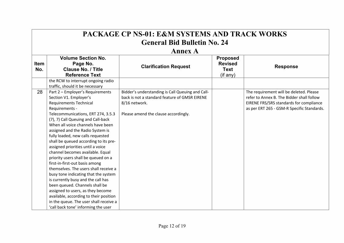
the RCW to interrupt ongoing radio traffic, should it be necessary
28 Part 2 – Employer’s Requirements Section V1. Employer’s Requirements Technical Requirements - Telecommunications, ERT 274, 3.5.3 (7), 7) Call Queuing and Call-back When all voice channels have been assigned and the Radio System is fully loaded, new calls requested shall be queued according to its pre-assigned priorities until a voice channel becomes available. Equal priority users shall be queued on a first-in-first-out basis among themselves. The users shall receive a busy tone indicating that the system is currently busy and the call has been queued. Channels shall be assigned to users, as they become available, according to their position in the queue. The user shall receive a ‘call back tone’ informing the user
Bidder’s understanding is Call Queuing and Call-back is not a standard feature of GMSR EIRENE 8/16 network. Please amend the clause accordingly.
The requirement will be deleted. Please refer to Annex B. The Bidder shall follow EIRENE FRS/SRS standards for compliance as per ERT 265 - GSM-R Specific Standards.
Page 13 of 19
PACKAGE CP NS-01: E&M SYSTEMS AND TRACK WORKS General Bid Bulletin No. 24
Annex A Item No.
Volume Section No. Page No.
Clause No. / Title Reference Text
Clarification Request Proposed Revised
Text (if any)
Response
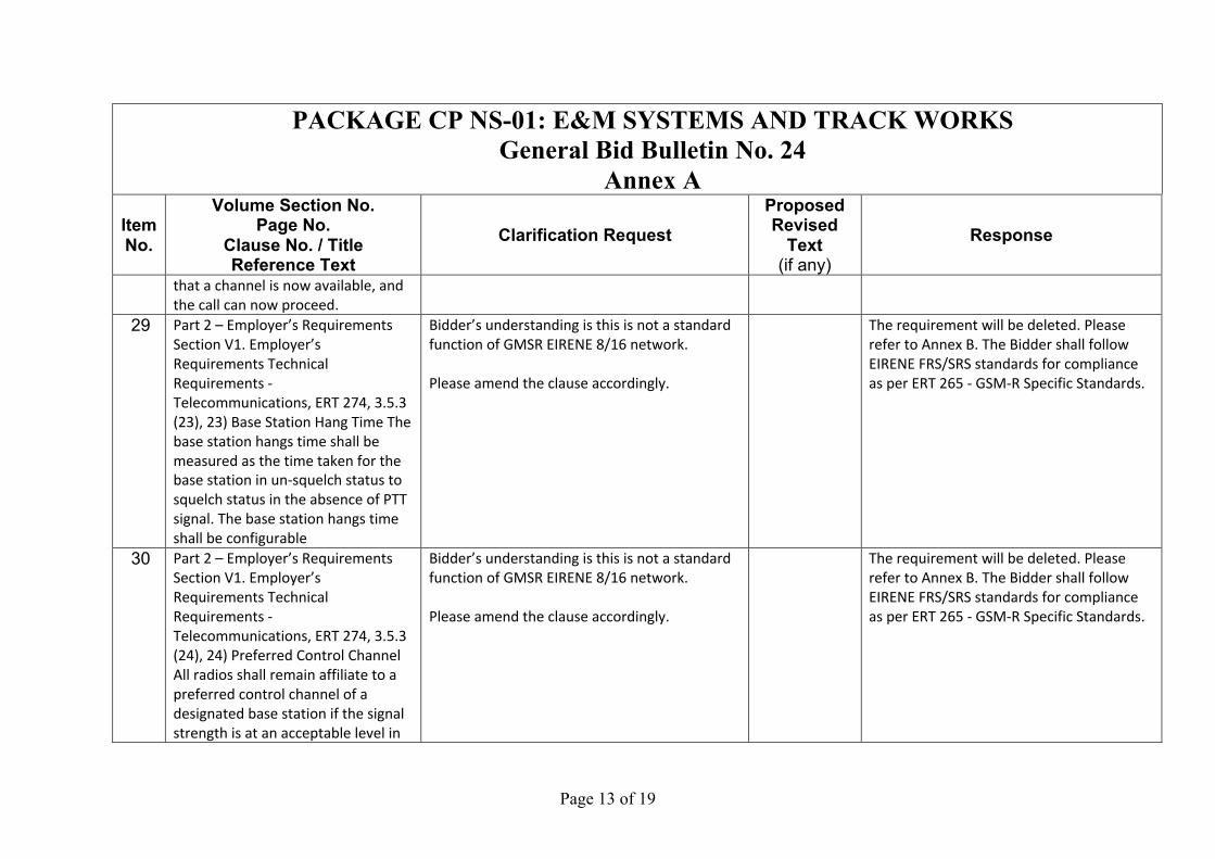
that a channel is now available, and the call can now proceed.
29 Part 2 – Employer’s Requirements Section V1. Employer’s Requirements Technical Requirements - Telecommunications, ERT 274, 3.5.3 (23), 23) Base Station Hang Time The base station hangs time shall be measured as the time taken for the base station in un-squelch status to squelch status in the absence of PTT signal. The base station hangs time shall be configurable
Bidder’s understanding is this is not a standard function of GMSR EIRENE 8/16 network. Please amend the clause accordingly.
The requirement will be deleted. Please refer to Annex B. The Bidder shall follow EIRENE FRS/SRS standards for compliance as per ERT 265 - GSM-R Specific Standards.
30 Part 2 – Employer’s Requirements Section V1. Employer’s Requirements Technical Requirements - Telecommunications, ERT 274, 3.5.3 (24), 24) Preferred Control Channel All radios shall remain affiliate to a preferred control channel of a designated base station if the signal strength is at an acceptable level in
Bidder’s understanding is this is not a standard function of GMSR EIRENE 8/16 network. Please amend the clause accordingly.
The requirement will be deleted. Please refer to Annex B. The Bidder shall follow EIRENE FRS/SRS standards for compliance as per ERT 265 - GSM-R Specific Standards.
Page 14 of 19
PACKAGE CP NS-01: E&M SYSTEMS AND TRACK WORKS General Bid Bulletin No. 24
Annex A Item No.
Volume Section No. Page No.
Clause No. / Title Reference Text
Clarification Request Proposed Revised
Text (if any)
Response
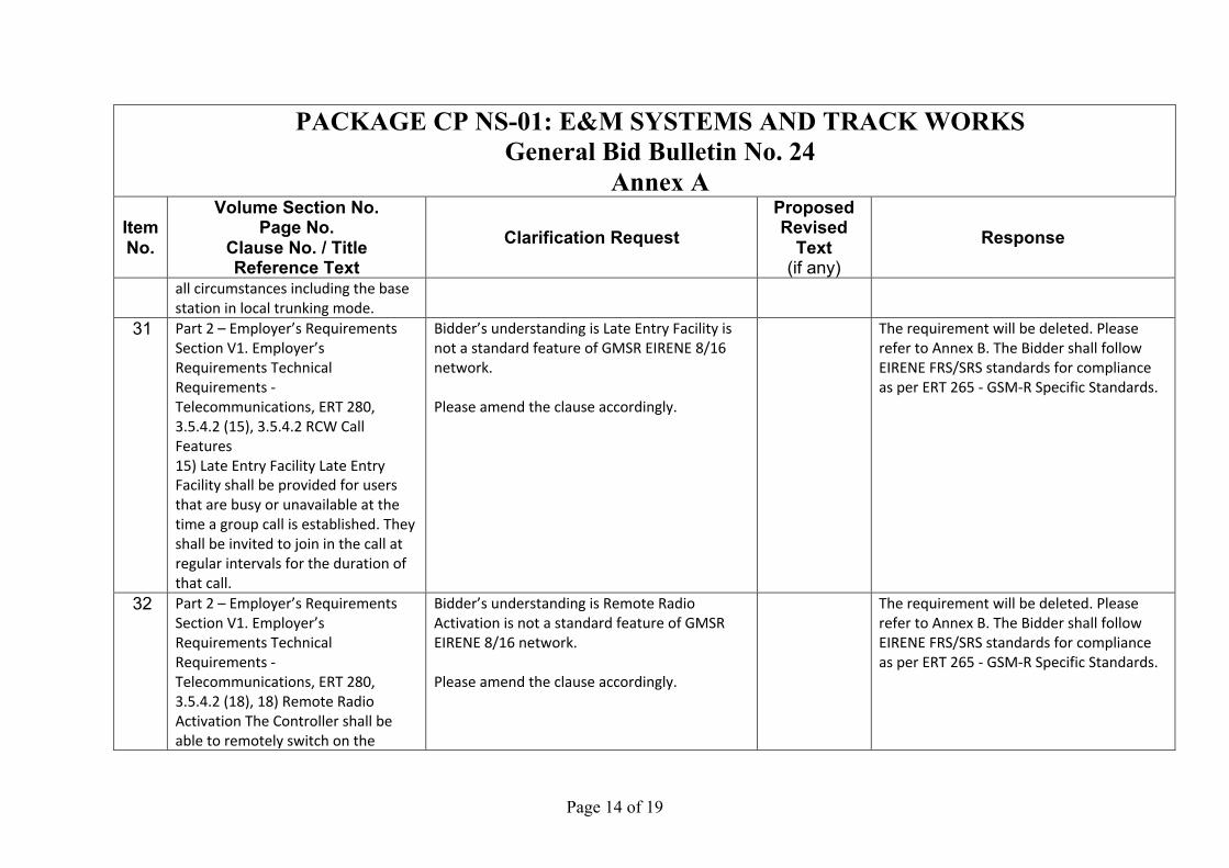
all circumstances including the base station in local trunking mode.
31 Part 2 – Employer’s Requirements Section V1. Employer’s Requirements Technical Requirements - Telecommunications, ERT 280, 3.5.4.2 (15), 3.5.4.2 RCW Call Features 15) Late Entry Facility Late Entry Facility shall be provided for users that are busy or unavailable at the time a group call is established. They shall be invited to join in the call at regular intervals for the duration of that call.
Bidder’s understanding is Late Entry Facility is not a standard feature of GMSR EIRENE 8/16 network. Please amend the clause accordingly.
The requirement will be deleted. Please refer to Annex B. The Bidder shall follow EIRENE FRS/SRS standards for compliance as per ERT 265 - GSM-R Specific Standards.
32 Part 2 – Employer’s Requirements Section V1. Employer’s Requirements Technical Requirements - Telecommunications, ERT 280, 3.5.4.2 (18), 18) Remote Radio Activation The Controller shall be able to remotely switch on the
Bidder’s understanding is Remote Radio Activation is not a standard feature of GMSR EIRENE 8/16 network. Please amend the clause accordingly.
The requirement will be deleted. Please refer to Annex B. The Bidder shall follow EIRENE FRS/SRS standards for compliance as per ERT 265 - GSM-R Specific Standards.
Page 15 of 19
PACKAGE CP NS-01: E&M SYSTEMS AND TRACK WORKS General Bid Bulletin No. 24
Annex A Item No.
Volume Section No. Page No.
Clause No. / Title Reference Text
Clarification Request Proposed Revised
Text (if any)
Response
microphone and transmitter of the Train radio or Hand-portable and listen to the received audio.
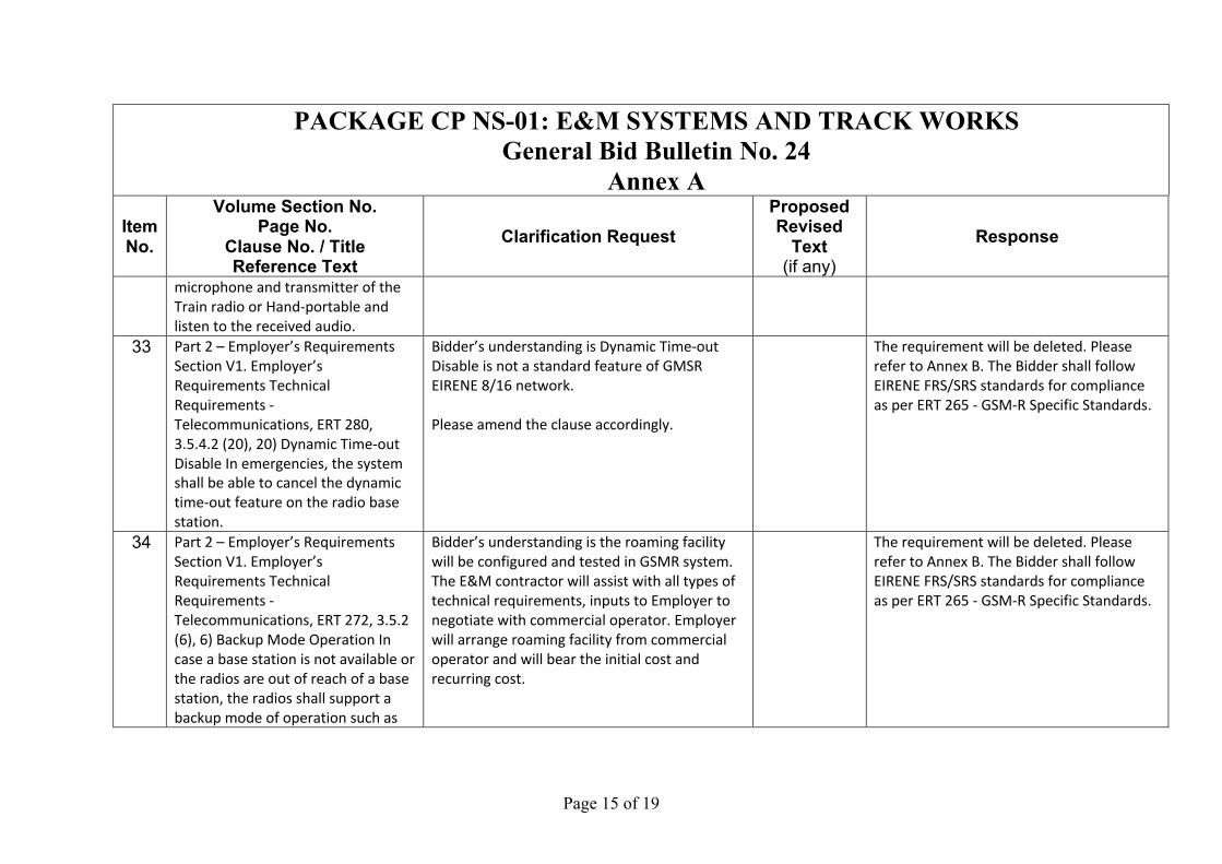
33 Part 2 – Employer’s Requirements Section V1. Employer’s Requirements Technical Requirements - Telecommunications, ERT 280, 3.5.4.2 (20), 20) Dynamic Time-out Disable In emergencies, the system shall be able to cancel the dynamic time-out feature on the radio base station.
Bidder’s understanding is Dynamic Time-out Disable is not a standard feature of GMSR EIRENE 8/16 network. Please amend the clause accordingly.
The requirement will be deleted. Please refer to Annex B. The Bidder shall follow EIRENE FRS/SRS standards for compliance as per ERT 265 - GSM-R Specific Standards.
34 Part 2 – Employer’s Requirements Section V1. Employer’s Requirements Technical Requirements - Telecommunications, ERT 272, 3.5.2 (6), 6) Backup Mode Operation In case a base station is not available or the radios are out of reach of a base station, the radios shall support a backup mode of operation such as
Bidder’s understanding is the roaming facility will be configured and tested in GSMR system. The E&M contractor will assist with all types of technical requirements, inputs to Employer to negotiate with commercial operator. Employer will arrange roaming facility from commercial operator and will bear the initial cost and recurring cost.
The requirement will be deleted. Please refer to Annex B. The Bidder shall follow EIRENE FRS/SRS standards for compliance as per ERT 265 - GSM-R Specific Standards.
Page 16 of 19
PACKAGE CP NS-01: E&M SYSTEMS AND TRACK WORKS General Bid Bulletin No. 24
Annex A Item No.
Volume Section No. Page No.
Clause No. / Title Reference Text
Clarification Request Proposed Revised
Text (if any)
Response
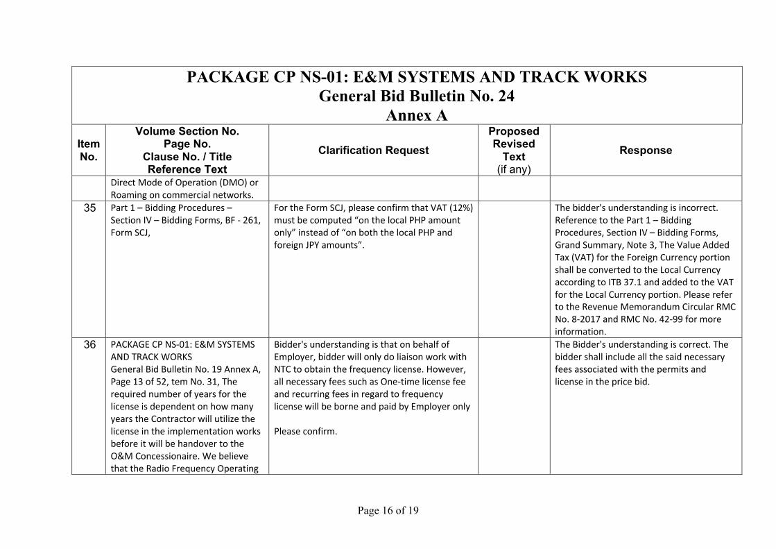
Direct Mode of Operation (DMO) or Roaming on commercial networks.
35 Part 1 – Bidding Procedures – Section IV – Bidding Forms, BF - 261, Form SCJ,
For the Form SCJ, please confirm that VAT (12%) must be computed “on the local PHP amount only” instead of “on both the local PHP and foreign JPY amounts”.
The bidder's understanding is incorrect. Reference to the Part 1 – Bidding Procedures, Section IV – Bidding Forms, Grand Summary, Note 3, The Value Added Tax (VAT) for the Foreign Currency portion shall be converted to the Local Currency according to ITB 37.1 and added to the VAT for the Local Currency portion. Please refer to the Revenue Memorandum Circular RMC No. 8-2017 and RMC No. 42-99 for more information.
36 PACKAGE CP NS-01: E&M SYSTEMS AND TRACK WORKS General Bid Bulletin No. 19 Annex A, Page 13 of 52, tem No. 31, The required number of years for the license is dependent on how many years the Contractor will utilize the license in the implementation works before it will be handover to the O&M Concessionaire. We believe that the Radio Frequency Operating
Bidder's understanding is that on behalf of Employer, bidder will only do liaison work with NTC to obtain the frequency license. However, all necessary fees such as One-time license fee and recurring fees in regard to frequency license will be borne and paid by Employer only Please confirm.
The Bidder's understanding is correct. The bidder shall include all the said necessary fees associated with the permits and license in the price bid.
Page 17 of 19
PACKAGE CP NS-01: E&M SYSTEMS AND TRACK WORKS General Bid Bulletin No. 24
Annex A Item No.
Volume Section No. Page No.
Clause No. / Title Reference Text
Clarification Request Proposed Revised
Text (if any)
Response
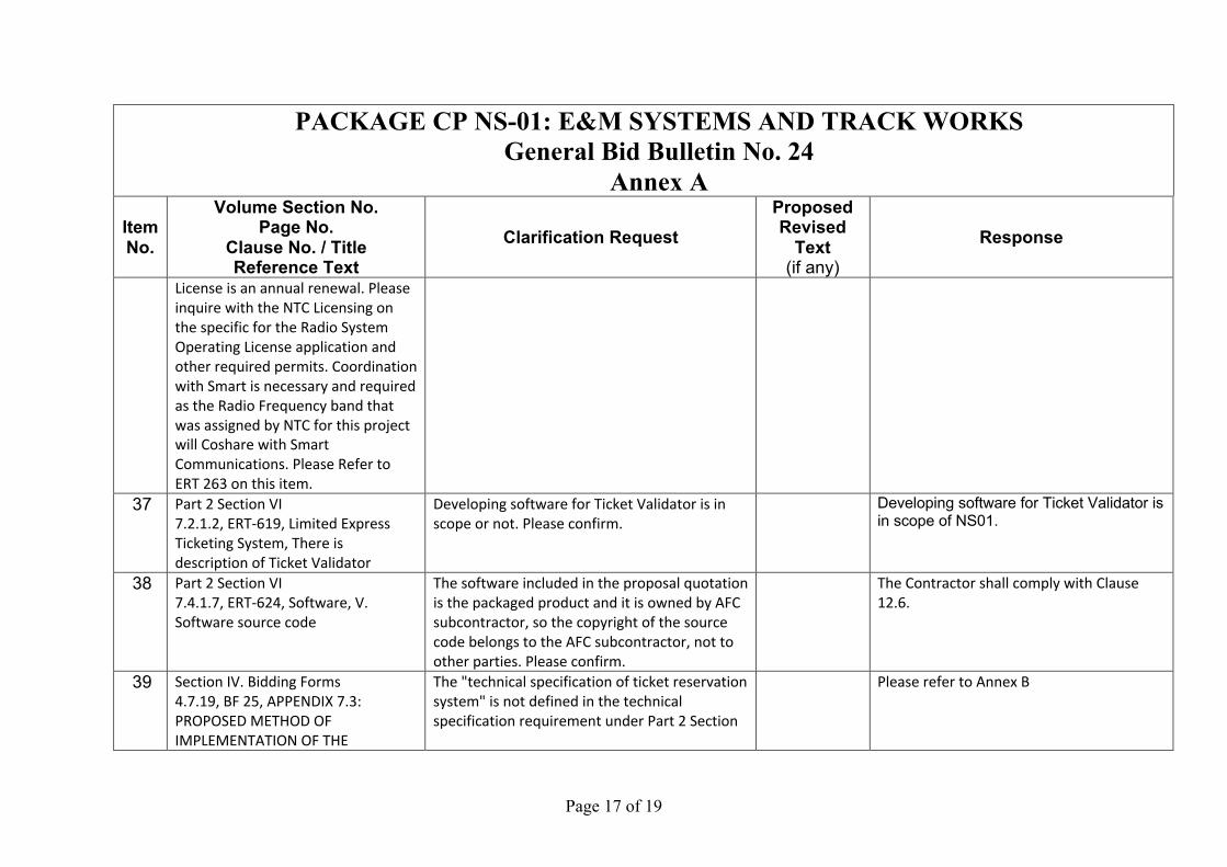
License is an annual renewal. Please inquire with the NTC Licensing on the specific for the Radio System Operating License application and other required permits. Coordination with Smart is necessary and required as the Radio Frequency band that was assigned by NTC for this project will Coshare with Smart Communications. Please Refer to ERT 263 on this item.
37 Part 2 Section VI 7.2.1.2, ERT-619, Limited Express Ticketing System, There is description of Ticket Validator
Developing software for Ticket Validator is in scope or not. Please confirm.
Developing software for Ticket Validator is in scope of NS01.
38 Part 2 Section VI 7.4.1.7, ERT-624, Software, V. Software source code
The software included in the proposal quotation is the packaged product and it is owned by AFC subcontractor, so the copyright of the source code belongs to the AFC subcontractor, not to other parties. Please confirm.
The Contractor shall comply with Clause 12.6.
39 Section IV. Bidding Forms 4.7.19, BF 25, APPENDIX 7.3: PROPOSED METHOD OF IMPLEMENTATION OF THE
The "technical specification of ticket reservation system" is not defined in the technical specification requirement under Part 2 Section
Please refer to Annex B
Page 18 of 19
PACKAGE CP NS-01: E&M SYSTEMS AND TRACK WORKS General Bid Bulletin No. 24
Annex A Item No.
Volume Section No. Page No.
Clause No. / Title Reference Text
Clarification Request Proposed Revised
Text (if any)
Response
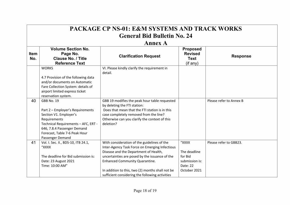
WORKS 4.7 Provision of the following data and/or documents on Automatic Fare Collection System: details of airport limited express ticket reservation system.
VI. Please kindly clarify the requirement in detail.
40 GBB No. 19 Part 2 – Employer’s Requirements Section V1. Employer’s Requirements Technical Requirements – AFC, ERT - 646, 7.8.4 Passenger Demand Forecast, Table 7-6 Peak Hour Passenger Demand
GBB 19 modifies the peak hour table requested by deleting the FTI station: Does that mean that the FTI station is in this case completely removed from the line? Otherwise can you clarify the context of this deletion?
Please refer to Annex B
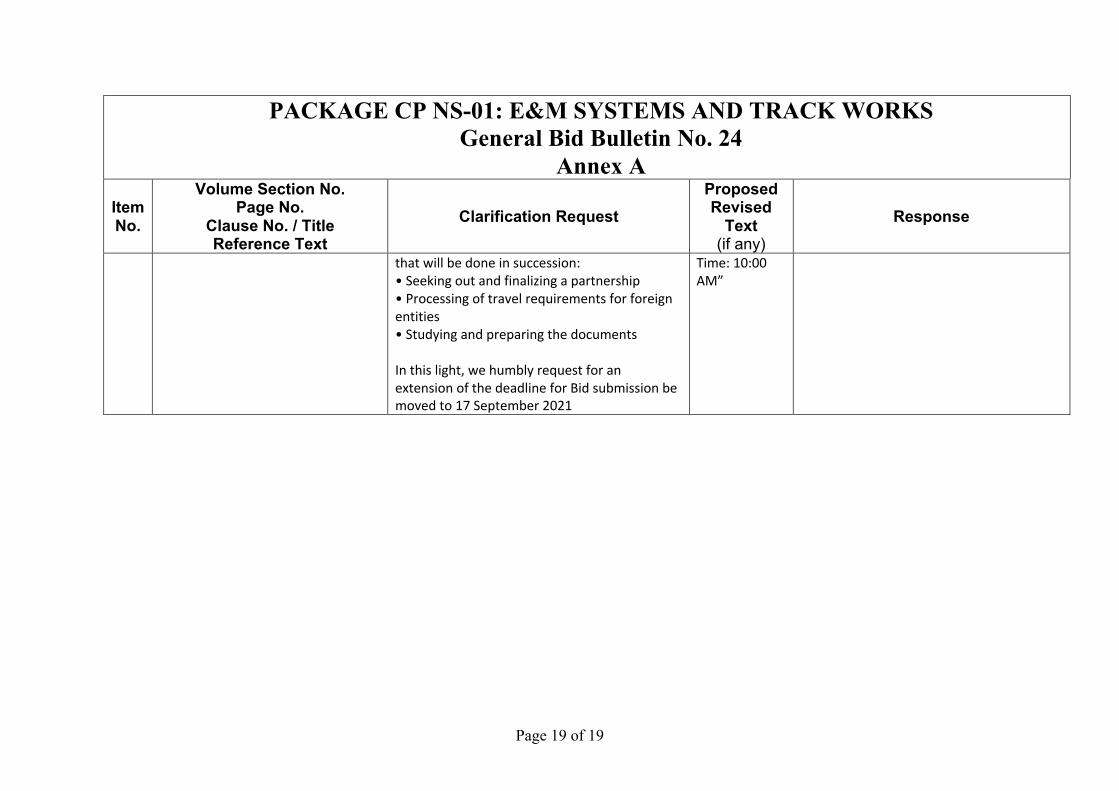
41 Vol. I. Sec. II., BDS-10, ITB 24.1, “XXXX The deadline for Bid submission is: Date: 23 August 2021 Time: 10:00 AM”
With consideration of the guidelines of the Inter-Agency Task Force on Emerging Infectious Disease and the Department of Health, uncertainties are posed by the issuance of the Enhanced Community Quarantine. In addition to this, two (2) months shall not be sufficient considering the following activities
“XXXX The deadline for Bid submission is: Date: 22 October 2021
Please refer to GBB23.
Page 19 of 19
PACKAGE CP NS-01: E&M SYSTEMS AND TRACK WORKS General Bid Bulletin No. 24
Annex A Item No.
Volume Section No. Page No.
Clause No. / Title Reference Text
Clarification Request Proposed Revised
Text (if any)
Response
that will be done in succession: • Seeking out and finalizing a partnership • Processing of travel requirements for foreign entities • Studying and preparing the documents In this light, we humbly request for an extension of the deadline for Bid submission be moved to 17 September 2021
Time: 10:00 AM”

Annex B
Page 2 of 6
PACKAGE CP NS-01: E&M SYSTEMS AND TRACK WORKS
General Bid Bulletin No. 24 Annex B
ITEM NO. REFERENCE/CLAUSE/SECTION
REVISIONS / AMENDMENTS
Volume I Part 1 – Bidding Procedures
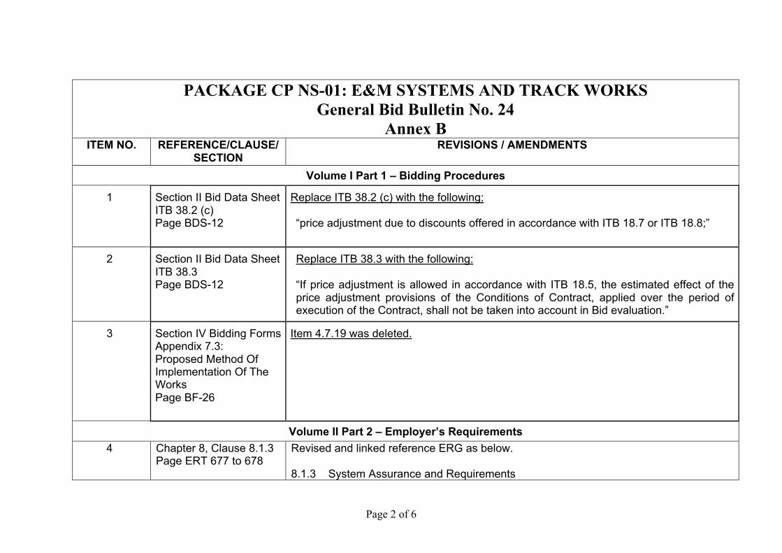
1 Section II Bid Data Sheet ITB 38.2 (c) Page BDS-12
Replace ITB 38.2 (c) with the following: “price adjustment due to discounts offered in accordance with ITB 18.7 or ITB 18.8;”
2 Section II Bid Data Sheet ITB 38.3 Page BDS-12
Replace ITB 38.3 with the following: “If price adjustment is allowed in accordance with ITB 18.5, the estimated effect of the price adjustment provisions of the Conditions of Contract, applied over the period of execution of the Contract, shall not be taken into account in Bid evaluation.”
3 Section IV Bidding Forms Appendix 7.3: Proposed Method Of Implementation Of The Works Page BF-26
Item 4.7.19 was deleted.
Volume II Part 2 – Employer’s Requirements 4 Chapter 8, Clause 8.1.3
Page ERT 677 to 678
Revised and linked reference ERG as below. 8.1.3 System Assurance and Requirements
Page 3 of 6
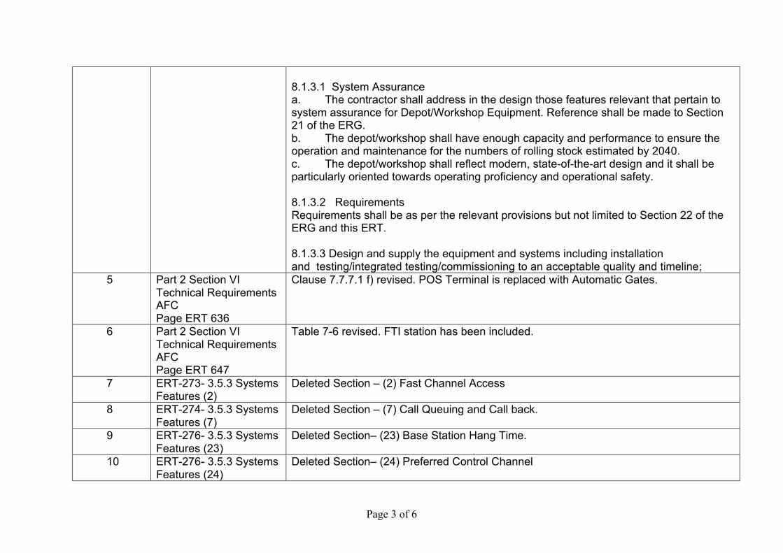
8.1.3.1 System Assurance a. The contractor shall address in the design those features relevant that pertain to system assurance for Depot/Workshop Equipment. Reference shall be made to Section 21 of the ERG. b. The depot/workshop shall have enough capacity and performance to ensure the operation and maintenance for the numbers of rolling stock estimated by 2040. c. The depot/workshop shall reflect modern, state-of-the-art design and it shall be particularly oriented towards operating proficiency and operational safety. 8.1.3.2 Requirements Requirements shall be as per the relevant provisions but not limited to Section 22 of the ERG and this ERT. 8.1.3.3 Design and supply the equipment and systems including installation and testing/integrated testing/commissioning to an acceptable quality and timeline;
5 Part 2 Section VI Technical Requirements AFC Page ERT 636
Clause 7.7.7.1 f) revised. POS Terminal is replaced with Automatic Gates.
6 Part 2 Section VI Technical Requirements AFC Page ERT 647
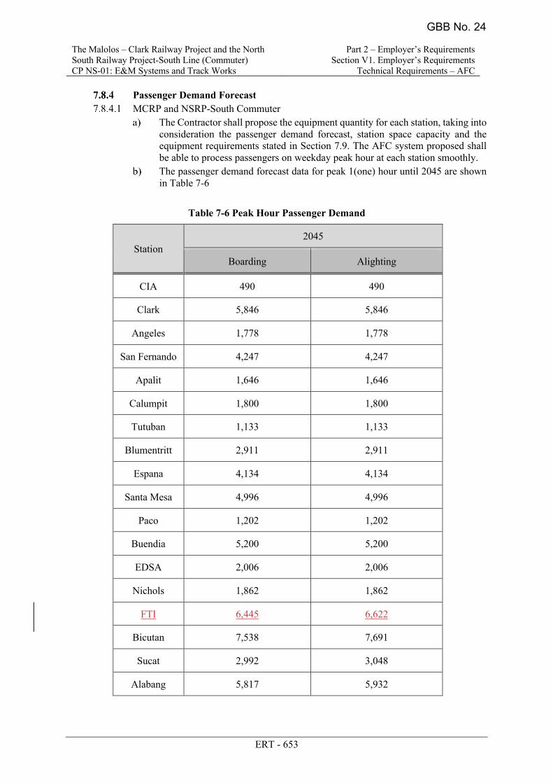
Table 7-6 revised. FTI station has been included.
7 ERT-273- 3.5.3 Systems Features (2)
Deleted Section – (2) Fast Channel Access
8 ERT-274- 3.5.3 Systems Features (7)
Deleted Section – (7) Call Queuing and Call back.
9 ERT-276- 3.5.3 Systems Features (23)
Deleted Section– (23) Base Station Hang Time.
10 ERT-276- 3.5.3 Systems Features (24)
Deleted Section– (24) Preferred Control Channel
Page 4 of 6
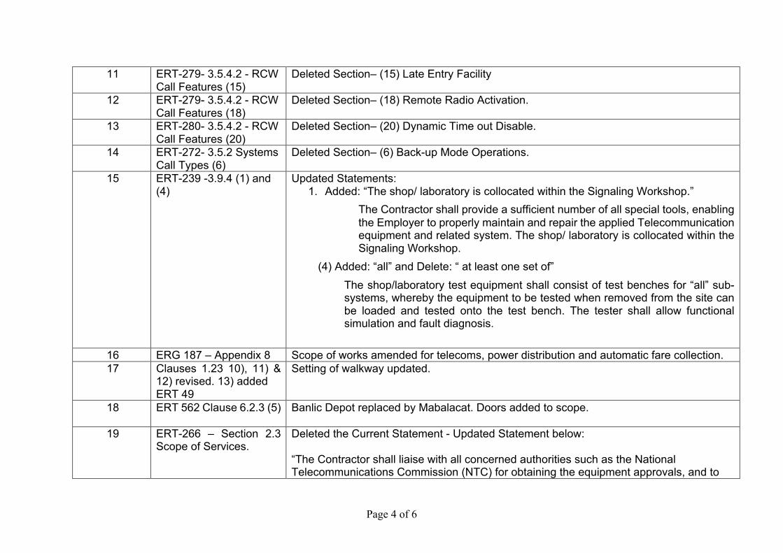
11 ERT-279- 3.5.4.2 - RCW Call Features (15)
Deleted Section– (15) Late Entry Facility
12 ERT-279- 3.5.4.2 - RCW Call Features (18)
Deleted Section– (18) Remote Radio Activation.
13 ERT-280- 3.5.4.2 - RCW Call Features (20)
Deleted Section– (20) Dynamic Time out Disable.
14 ERT-272- 3.5.2 Systems Call Types (6)
Deleted Section– (6) Back-up Mode Operations.
15 ERT-239 -3.9.4 (1) and (4)
Updated Statements: 1. Added: “The shop/ laboratory is collocated within the Signaling Workshop.”
The Contractor shall provide a sufficient number of all special tools, enabling the Employer to properly maintain and repair the applied Telecommunication equipment and related system. The shop/ laboratory is collocated within the Signaling Workshop.
(4) Added: “all” and Delete: “ at least one set of” The shop/laboratory test equipment shall consist of test benches for “all” sub-systems, whereby the equipment to be tested when removed from the site can be loaded and tested onto the test bench. The tester shall allow functional simulation and fault diagnosis.
16 ERG 187 – Appendix 8 Scope of works amended for telecoms, power distribution and automatic fare collection. 17 Clauses 1.23 10), 11) &
12) revised. 13) added ERT 49
Setting of walkway updated.
18 ERT 562 Clause 6.2.3 (5) Banlic Depot replaced by Mabalacat. Doors added to scope.
19 ERT-266 – Section 2.3 Scope of Services.
Deleted the Current Statement - Updated Statement below: “The Contractor shall liaise with all concerned authorities such as the National Telecommunications Commission (NTC) for obtaining the equipment approvals, and to
Page 5 of 6
any other authorities to obtain any necessary licenses, clearances, or permits for the supply, installation and commissioning of the Radio System. The Radio Frequency Operating License shall be applied and obtained by the Employer with the NTC, as the Employer will be the Owner of the Frequency Band.”
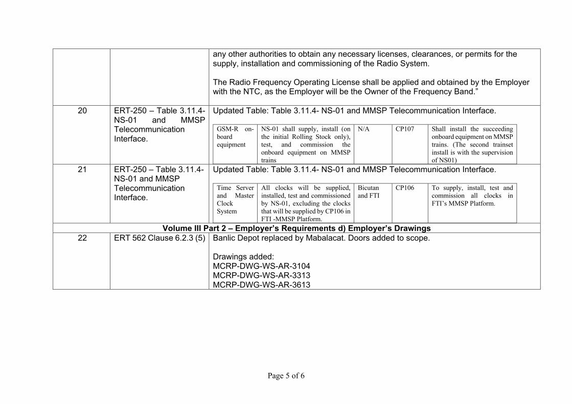
20 ERT-250 – Table 3.11.4- NS-01 and MMSP Telecommunication Interface.
Updated Table: Table 3.11.4- NS-01 and MMSP Telecommunication Interface.
GSM-R on-board equipment
NS-01 shall supply, install (on the initial Rolling Stock only), test, and commission the onboard equipment on MMSP trains
N/A CP107 Shall install the succeeding onboard equipment on MMSP trains. (The second trainset install is with the supervision of NS01)
21 ERT-250 – Table 3.11.4- NS-01 and MMSP Telecommunication Interface.
Updated Table: Table 3.11.4- NS-01 and MMSP Telecommunication Interface.
Time Server and Master Clock System
All clocks will be supplied, installed, test and commissioned by NS-01, excluding the clocks that will be supplied by CP106 in FTI -MMSP Platform.
Bicutan and FTI
CP106 To supply, install, test and commission all clocks in FTI’s MMSP Platform.
Volume III Part 2 – Employer’s Requirements d) Employer’s Drawings 22 ERT 562 Clause 6.2.3 (5)
Banlic Depot replaced by Mabalacat. Doors added to scope. Drawings added: MCRP-DWG-WS-AR-3104 MCRP-DWG-WS-AR-3313 MCRP-DWG-WS-AR-3613
Annex B – Attachment 1
The Malolos–Clark Railway Project and the North South Railway Project-South Line (Commuter) CP NS-01: E&M Systems and Track Works
Part 1 – Bidding Procedures Section II. Bid Data Sheet
BDS - 12
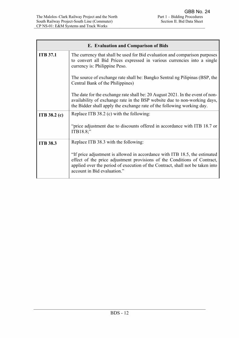
E. Evaluation and Comparison of Bids
ITB 37.1
The currency that shall be used for Bid evaluation and comparison purposes to convert all Bid Prices expressed in various currencies into a single currency is: Philippine Peso.
The source of exchange rate shall be: Bangko Sentral ng Pilipinas (BSP, the Central Bank of the Philippines)
The date for the exchange rate shall be: 20 August 2021. In the event of non-availability of exchange rate in the BSP website due to non-working days, the Bidder shall apply the exchange rate of the following working day.
ITB 38.2 (c) Replace ITB 38.2 (c) with the following:
“price adjustment due to discounts offered in accordance with ITB 18.7 or ITB18.8;”
ITB 38.3 Replace ITB 38.3 with the following: “If price adjustment is allowed in accordance with ITB 18.5, the estimated effect of the price adjustment provisions of the Conditions of Contract, applied over the period of execution of the Contract, shall not be taken into account in Bid evaluation.”
GBB No. 24
The Malolos–Clark Railway Project and the North South Railway Project-South Line (Commuter) CP NS-01: E&M Systems and Track Works
Part 1 – Bidding Procedures Section II. Bid Data Sheet
BDS - 12
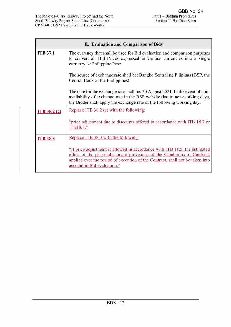
E. Evaluation and Comparison of Bids
ITB 37.1
The currency that shall be used for Bid evaluation and comparison purposes to convert all Bid Prices expressed in various currencies into a single currency is: Philippine Peso.
The source of exchange rate shall be: Bangko Sentral ng Pilipinas (BSP, the Central Bank of the Philippines)
The date for the exchange rate shall be: 20 August 2021. In the event of non-availability of exchange rate in the BSP website due to non-working days, the Bidder shall apply the exchange rate of the following working day.
ITB 38.2 (c) Replace ITB 38.2 (c) with the following:
“price adjustment due to discounts offered in accordance with ITB 18.7 or ITB18.8;”
ITB 38.3 Replace ITB 38.3 with the following: “If price adjustment is allowed in accordance with ITB 18.5, the estimated effect of the price adjustment provisions of the Conditions of Contract, applied over the period of execution of the Contract, shall not be taken into account in Bid evaluation.”
GBB No. 24
The Malolos–Clark Railway Project and the North South Railway Project-South Line (Commuter) CP NS-01: E&M Systems and Track Works
Part 1 – Bidding Procedures Section IV. Bidding Forms
BF - 26
4.8 Provision of the following data and/or documents on Depot Facility:
4.8.1 details of the national or international standards and codes to be used for system design;
4.8.2 drawings of Depot and Workshop Equipment layout;
4.8.3 flow of rolling stock maintenance for every inspection and heavy maintenance;
4.8.4 calculation of rolling stock maintenance capacity with assumptions of manpower and period of maintenance works;
4.8.5 calculation of capacity of rolling stock wash plant;
4.8.6 calculation of capacity of wheel profiling plant;
4.8.7 specifications for Depot and Workshop Equipment;
4.8.8 drawings for infrastructure maintenance workshop equipment layout;
4.8.9 calculation of maintenance capacity with assumptions of manpower and period of maintenance works;
4.8.10 details of the provisions made for interfaces with other Interface Contractors;
4.8.11 preliminary provisions made for interfaces with Railway System Packages; and
4.8.12 estimates of electric power demand.
4.9 Provision of the following data and/or documents on Platform Screen Doors
4.9.1 details of the nationals or international standards and codes to be used for system design:
4.9.2 schematic drawings of the proposed PSD system;
4.9.3 specifications for PSD;
4.9.4 schematic drawings of the proposed PSD;
4.9.5 drawings for layouts of PSD; and
4.9.6 drawings of outline of machines
4.10 Provision of the following data and/or documents on Computerized Maintenance Management System (CMMS):
GBB No. 24
The Malolos–Clark Railway Project and the North South Railway Project-South Line (Commuter) CP NS-01: E&M Systems and Track Works
Part 1 – Bidding Procedures Section IV. Bidding Forms
BF - 26
4.7.19 details of airport limited express ticket reservation system.
4.8 Provision of the following data and/or documents on Depot Facility:
4.8.1 details of the national or international standards and codes to be used for system design;
4.8.2 drawings of Depot and Workshop Equipment layout;
4.8.3 flow of rolling stock maintenance for every inspection and heavy maintenance;
4.8.4 calculation of rolling stock maintenance capacity with assumptions of manpower and period of maintenance works;
4.8.5 calculation of capacity of rolling stock wash plant;
4.8.6 calculation of capacity of wheel profiling plant;
4.8.7 specifications for Depot and Workshop Equipment;
4.8.8 drawings for infrastructure maintenance workshop equipment layout;
4.8.9 calculation of maintenance capacity with assumptions of manpower and period of maintenance works;
4.8.10 details of the provisions made for interfaces with other Interface Contractors;
4.8.11 preliminary provisions made for interfaces with Railway System Packages; and
4.8.12 estimates of electric power demand.
4.9 Provision of the following data and/or documents on Platform Screen Doors
4.9.1 details of the nationals or international standards and codes to be used for system design:
4.9.2 schematic drawings of the proposed PSD system;
4.9.3 specifications for PSD;
4.9.4 schematic drawings of the proposed PSD;
4.9.5 drawings for layouts of PSD; and
4.9.6 drawings of outline of machines
4.10 Provision of the following data and/or documents on Computerized Maintenance Management System (CMMS):
GBB No. 24
The Malolos – Clark Railway Project and the North
South Railway Project-South Line (Commuter)
CP NS-01: E&M Systems and Track Works
Part 2 – Employer’s Requirements
Section V1. Employer’s Requirements
Technical Requirements -Depot Facilities
ERT - 677
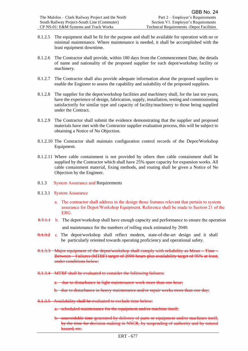
8.1.2.5 The equipment shall be fit for the purpose and shall be available for operation with no or
minimal maintenance. Where maintenance is needed, it shall be accomplished with the
least equipment downtime.
8.1.2.6 The Contractor shall provide, within 180 days from the Commencement Date, the details
of name and nationality of the proposed supplier for each depot/workshop facility or
machinery.
8.1.2.7 The Contractor shall also provide adequate information about the proposed suppliers to
enable the Engineer to assess the capability and suitability of the proposed suppliers.
8.1.2.8 The supplier for the depot/workshop facilities and machinery shall, for the last ten years,
have the experience of design, fabrication, supply, installation, testing and commissioning
satisfactorily for similar type and capacity of facility/machinery to those being supplied
under the Contract.
8.1.2.9 The Contractor shall submit the evidence demonstrating that the supplier and proposed
materials have met with the Contractor supplier evaluation process, this will be subject to
obtaining a Notice of No Objection.
8.1.2.10 The Contractor shall maintain configuration control records of the Depot/Workshop
Equipment.
8.1.2.11 Where cable containment is not provided by others then cable containment shall be
supplied by the Contractor which shall have 25% spare capacity for expansion works. All
cable containment material, fixing methods, and routing shall be given a Notice of No
Objection by the Engineer.
8.1.3 System Assurance and Requirements
8.1.3.1 System Assurance
a. The contractor shall address in the design those features relevant that pertain to system
assurance for Depot/Workshop Equipment. Reference shall be made to Section 21 of
the ERG.
b. The depot/workshop shall have enough capacity and performance to ensure the
operation and maintenance for the numbers of rolling stock estimated by 2040.
c. The depot/workshop shall reflect modern, state-of-the-art design and it shall be
particularly oriented towards operating proficiency and operational safety.
8.1.3.2 Requirements
Requirements shall be as per the relevant provisions but not limited to Section 22 of the
ERG and this ERT.
8.1.3.3 Design and supply the equipment and systems including installation and testing/integrated
testing/commissioning to an acceptable quality and timeline;
a. Presentations, reviews and offer audit support as specified, but not limited to, this ERT
and ERG;
GBB No. 24
The Malolos – Clark Railway Project and the North
South Railway Project-South Line (Commuter)
CP NS-01: E&M Systems and Track Works
Part 2 – Employer’s Requirements
Section V1. Employer’s Requirements
Technical Requirements -Depot Facilities
ERT - 678
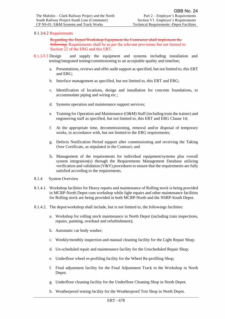
b. Interface management as specified, but not limited to, this ERT and ERG;
c. Identification of locations, design and installation for concrete foundations, to
accommodate piping and wiring etc.;
d. Systems operation and maintenance support services;
e. Training for Operation and Maintenance (O&M) Staff (including train the trainer) and
engineering staff as specified, but not limited to, this ERT and ERG Clause 14;
f. At the appropriate time, decommissioning, removal and/or disposal of temporary
works, in accordance with, but not limited to the ERG requirements;
g. Defects Notification Period support after commissioning and receiving the Taking
Over Certificate, as stipulated in the Contract; and
h. Management of the requirements for individual equipment/systems plus overall
system integration(s) through the Requirements Management Database utilizing
verification and validation (V&V) procedures to ensure that the requirements are fully
satisfied according to the requirements.
8.1.4 System Overview
8.1.4.1. Workshop facilities for Heavy repairs and maintenance of Rolling stock is being provided
in MCRP-North Depot cum workshop while light repairs and other maintenance facilities
for Rolling stock are being provided in both MCRP-North and the NSRP-South Depot.
8.1.4.2. The depot/workshop shall include, but is not limited to, the followings facilities:
a. Workshop for rolling stock maintenance in North Depot (including train inspections,
repairs, painting, overhaul and refurbishment);
b. Automatic car body washer;
c. Weekly/monthly inspection and manual cleaning facility for the Light Repair Shop;
d. Un-scheduled repair and maintenance facility for the Unscheduled Repair Shop;
e. Underfloor wheel re-profiling facility for the Wheel Re-profiling Shop;
f. Final adjustment facility for the Final Adjustment Track in the Workshop in North
Depot.
g. Underfloor cleaning facility for the Underfloor Cleaning Shop in North Depot.
h. Weatherproof testing facility for the Weatherproof Test Shop in North Depot.
i. Automobile maintenance facility for the Automobile Maintenance Shop;
j. Shunting Locomotives
k. Test track in North Depot across road, fitted with flashing lights and klaxon to notify
all personnel that testing is being undertaken; and
GBB No. 24
The Malolos – Clark Railway Project and the North
South Railway Project-South Line (Commuter)
CP NS-01: E&M Systems and Track Works
Part 2 – Employer’s Requirements
Section V1. Employer’s Requirements
Technical Requirements -Depot Facilities
ERT - 677
8.1.2.5 The equipment shall be fit for the purpose and shall be available for operation with no or
minimal maintenance. Where maintenance is needed, it shall be accomplished with the
least equipment downtime.
8.1.2.6 The Contractor shall provide, within 180 days from the Commencement Date, the details
of name and nationality of the proposed supplier for each depot/workshop facility or
machinery.
8.1.2.7 The Contractor shall also provide adequate information about the proposed suppliers to
enable the Engineer to assess the capability and suitability of the proposed suppliers.
8.1.2.8 The supplier for the depot/workshop facilities and machinery shall, for the last ten years,
have the experience of design, fabrication, supply, installation, testing and commissioning
satisfactorily for similar type and capacity of facility/machinery to those being supplied
under the Contract.
8.1.2.9 The Contractor shall submit the evidence demonstrating that the supplier and proposed
materials have met with the Contractor supplier evaluation process, this will be subject to
obtaining a Notice of No Objection.
8.1.2.10 The Contractor shall maintain configuration control records of the Depot/Workshop
Equipment.
8.1.2.11 Where cable containment is not provided by others then cable containment shall be
supplied by the Contractor which shall have 25% spare capacity for expansion works. All
cable containment material, fixing methods, and routing shall be given a Notice of No
Objection by the Engineer.
and maintenance for the numbers of rolling stock estimated by 2040.
8.1.3 System Assurance and Requirements
8.1.3.1 System Assurance
a. The contractor shall address in the design those features relevant that pertain to system assurance for Depot/Workshop Equipment. Reference shall be made to Section 21 of the ERG.
8.3.1.1 b. The depot/workshop shall have enough capacity and performance to ensure the operation
8.1.3.2 c. The depot/workshop shall reflect modern, state-of-the-art design and it shall be particularly oriented towards operating proficiency and operational safety.
8.1.3.3 Major equipment of the depot/workshop shall comply with reliability as Mean – Time –
Between – Failures (MTBF) target of 2000 hours plus availability target of 95% at least,
under conditions below:
8.1.3.4 MTBF shall be evaluated to consider the following failures:
a. due to disturbance in light maintenance work more than one hour;
b. due to disturbance in heavy maintenance and/or repair works more than one day;
8.1.3.5 Availability shall be evaluated to exclude time below:
a. scheduled maintenance for the equipment and/or machine itself;
b. unavoidable time generated by delivery of parts or equipment and/or machines itself,
by the time for decision making in NSCR, by suspending of authority and by natural
hazard, etc.
GBB No. 24
User
Cross-Out
User
Cross-Out
User
Cross-Out
User
Cross-Out
User
Cross-Out
User
Cross-Out
User
Cross-Out
User
Cross-Out
User
Cross-Out
The Malolos – Clark Railway Project and the North
South Railway Project-South Line (Commuter)
CP NS-01: E&M Systems and Track Works
Part 2 – Employer’s Requirements
Section V1. Employer’s Requirements
Technical Requirements -Depot Facilities
ERT - 678
a. Presentations, reviews and offer audit support as specified, but not limited to, this ERT
and ERG;
b. Interface management as specified, but not limited to, this ERT and ERG;
c. Identification of locations, design and installation for concrete foundations, to
accommodate piping and wiring etc.;
d. Systems operation and maintenance support services;
e. Training for Operation and Maintenance (O&M) Staff (including train the trainer) and
engineering staff as specified, but not limited to, this ERT and ERG Clause 14;
f. At the appropriate time, decommissioning, removal and/or disposal of temporary
works, in accordance with, but not limited to the ERG requirements;
g. Defects Notification Period support after commissioning and receiving the Taking
Over Certificate, as stipulated in the Contract; and
h. Management of the requirements for individual equipment/systems plus overall
system integration(s) through the Requirements Management Database utilizing
verification and validation (V&V) procedures to ensure that the requirements are fully
satisfied according to the requirements.
8.1.4 System Overview
8.1.4.1. Workshop facilities for Heavy repairs and maintenance of Rolling stock is being provided
in MCRP-North Depot cum workshop while light repairs and other maintenance facilities
for Rolling stock are being provided in both MCRP-North and the NSRP-South Depot.
8.1.4.2. The depot/workshop shall include, but is not limited to, the followings facilities:
a. Workshop for rolling stock maintenance in North Depot (including train inspections,
repairs, painting, overhaul and refurbishment);
b. Automatic car body washer;
c. Weekly/monthly inspection and manual cleaning facility for the Light Repair Shop;
d. Un-scheduled repair and maintenance facility for the Unscheduled Repair Shop;
e. Underfloor wheel re-profiling facility for the Wheel Re-profiling Shop;
f. Final adjustment facility for the Final Adjustment Track in the Workshop in North
Depot.
g. Underfloor cleaning facility for the Underfloor Cleaning Shop in North Depot.
h. Weatherproof testing facility for the Weatherproof Test Shop in North Depot.
8.1.3.6.2 Requirements
8.1.3.7.3 Design and supply the equipment and systems including installation and
testing/integrated testing/commissioning to an acceptable quality and timeline;
Regarding the Depot/Workshop Equipment the Contractor shall implement the following: Requirements shall be as per the relevant provisions but not limited to Section 22 of the ERG and this ERT.
GBB No. 24
User
Cross-Out
User
Cross-Out
User
Cross-Out
The Malolos – Clark Railway Project and the North South Railway Project-South Line (Commuter) CP NS-01: E&M Systems and Track Works
Part 2 – Employer’s Requirements Section V1. Employer’s Requirements
Technical Requirements – AFC
ERT - 647
Auditability The AFC system shall provide fully auditable accounting records and shall be able to
store Transaction Records and all other usage data (including, but not limited to, Device status messages), securely and indefinitely.
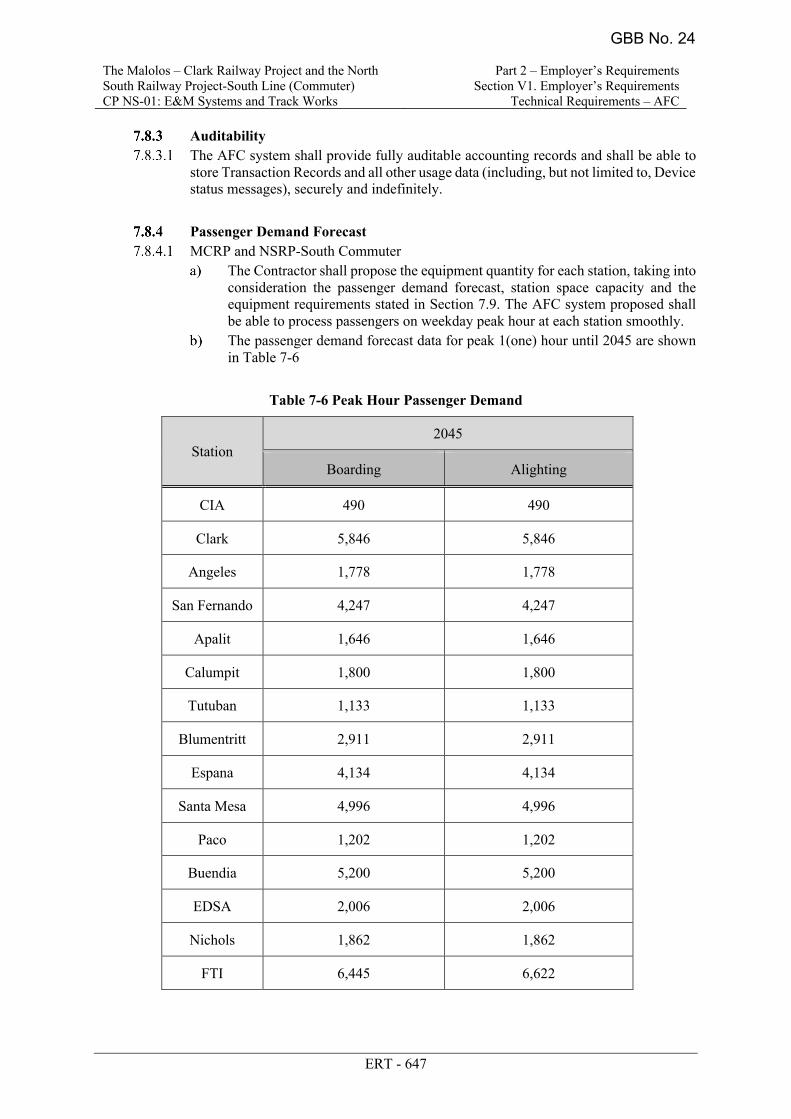
Passenger Demand Forecast MCRP and NSRP-South Commuter
The Contractor shall propose the equipment quantity for each station, taking into consideration the passenger demand forecast, station space capacity and the equipment requirements stated in Section 7.9. The AFC system proposed shall be able to process passengers on weekday peak hour at each station smoothly.
The passenger demand forecast data for peak 1(one) hour until 2045 are shown in Table 7-6
Table 7-6 Peak Hour Passenger Demand
Station 2045
Boarding Alighting
CIA 490 490
Clark 5,846 5,846
Angeles 1,778 1,778
San Fernando 4,247 4,247
Apalit 1,646 1,646
Calumpit 1,800 1,800
Tutuban 1,133 1,133
Blumentritt 2,911 2,911
Espana 4,134 4,134
Santa Mesa 4,996 4,996
Paco 1,202 1,202
Buendia 5,200 5,200
EDSA 2,006 2,006
Nichols 1,862 1,862
FTI 6,445 6,622
GBB No. 24
The Malolos – Clark Railway Project and the North South Railway Project-South Line (Commuter) CP NS-01: E&M Systems and Track Works
Part 2 – Employer’s Requirements Section V1. Employer’s Requirements
Technical Requirements – AFC
ERT - 653
Passenger Demand Forecast MCRP and NSRP-South Commuter
The Contractor shall propose the equipment quantity for each station, taking into consideration the passenger demand forecast, station space capacity and the equipment requirements stated in Section 7.9. The AFC system proposed shall be able to process passengers on weekday peak hour at each station smoothly.
The passenger demand forecast data for peak 1(one) hour until 2045 are shown in Table 7-6
Table 7-6 Peak Hour Passenger Demand
Station 2045
Boarding Alighting
CIA 490 490
Clark 5,846 5,846
Angeles 1,778 1,778
San Fernando 4,247 4,247
Apalit 1,646 1,646
Calumpit 1,800 1,800
Tutuban 1,133 1,133
Blumentritt 2,911 2,911
Espana 4,134 4,134
Santa Mesa 4,996 4,996
Paco 1,202 1,202
Buendia 5,200 5,200
EDSA 2,006 2,006
Nichols 1,862 1,862
FTI 6,445 6,622
Bicutan 7,538 7,691
Sucat 2,992 3,048
Alabang 5,817 5,932
GBB No. 24
The Malolos – Clark Railway Project and the North South Railway Project-South Line (Commuter) CP NS-01: E&M Systems and Track Works
Part 2 – Employer’s Requirements Section V1. Employer’s Requirements
Technical Requirements – AFC
ERT - 636
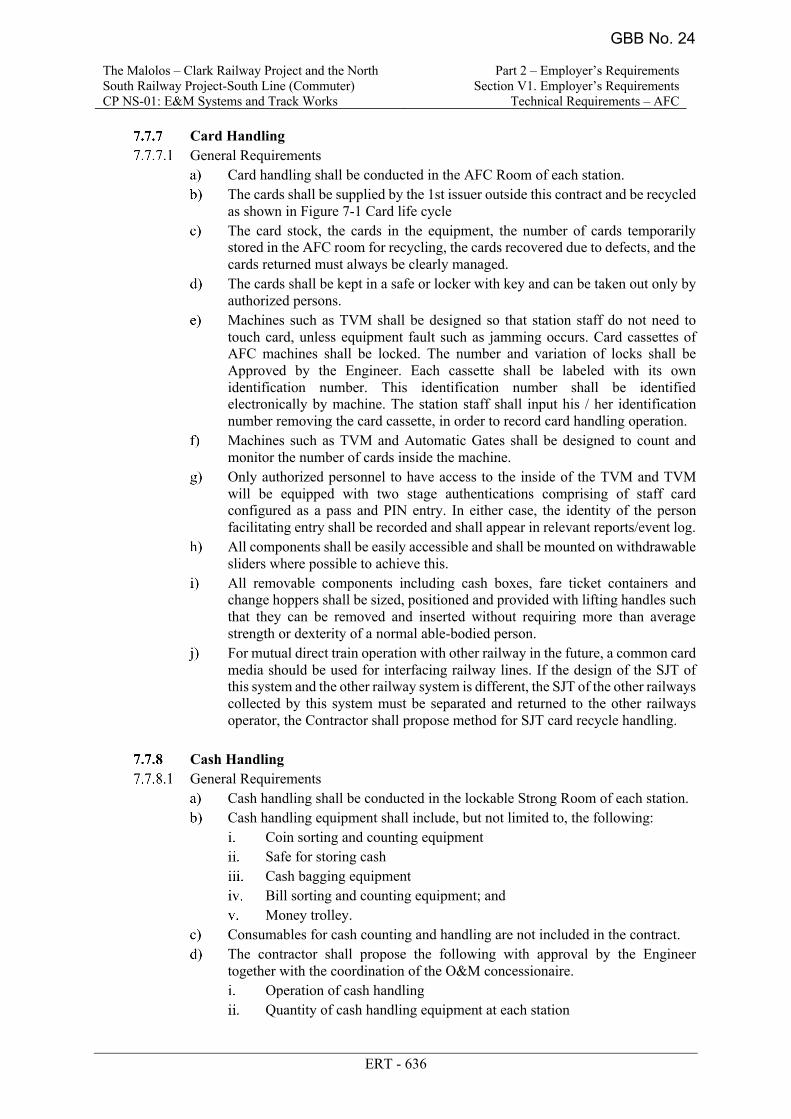
Card Handling General Requirements
Card handling shall be conducted in the AFC Room of each station. The cards shall be supplied by the 1st issuer outside this contract and be recycled
as shown in Figure 7-1 Card life cycle The card stock, the cards in the equipment, the number of cards temporarily
stored in the AFC room for recycling, the cards recovered due to defects, and the cards returned must always be clearly managed.
The cards shall be kept in a safe or locker with key and can be taken out only by authorized persons.
Machines such as TVM shall be designed so that station staff do not need to touch card, unless equipment fault such as jamming occurs. Card cassettes of AFC machines shall be locked. The number and variation of locks shall be Approved by the Engineer. Each cassette shall be labeled with its own identification number. This identification number shall be identified electronically by machine. The station staff shall input his / her identification number removing the card cassette, in order to record card handling operation.
Machines such as TVM and Automatic Gates shall be designed to count and monitor the number of cards inside the machine.
Only authorized personnel to have access to the inside of the TVM and TVM will be equipped with two stage authentications comprising of staff card configured as a pass and PIN entry. In either case, the identity of the person facilitating entry shall be recorded and shall appear in relevant reports/event log.
All components shall be easily accessible and shall be mounted on withdrawable sliders where possible to achieve this.
All removable components including cash boxes, fare ticket containers and change hoppers shall be sized, positioned and provided with lifting handles such that they can be removed and inserted without requiring more than average strength or dexterity of a normal able-bodied person.
For mutual direct train operation with other railway in the future, a common card media should be used for interfacing railway lines. If the design of the SJT of this system and the other railway system is different, the SJT of the other railways collected by this system must be separated and returned to the other railways operator, the Contractor shall propose method for SJT card recycle handling.
Cash Handling
General Requirements Cash handling shall be conducted in the lockable Strong Room of each station. Cash handling equipment shall include, but not limited to, the following:
Coin sorting and counting equipment Safe for storing cash Cash bagging equipment Bill sorting and counting equipment; and Money trolley.
Consumables for cash counting and handling are not included in the contract. The contractor shall propose the following with approval by the Engineer
together with the coordination of the O&M concessionaire. Operation of cash handling Quantity of cash handling equipment at each station
GBB No. 24
The Malolos – Clark Railway Project and the North South Railway Project-South Line (Commuter) CP NS-01: E&M Systems and Track Works
Part 2 – Employer’s Requirements Section V1. Employer’s Requirements
Technical Requirements – AFC
ERT - 636
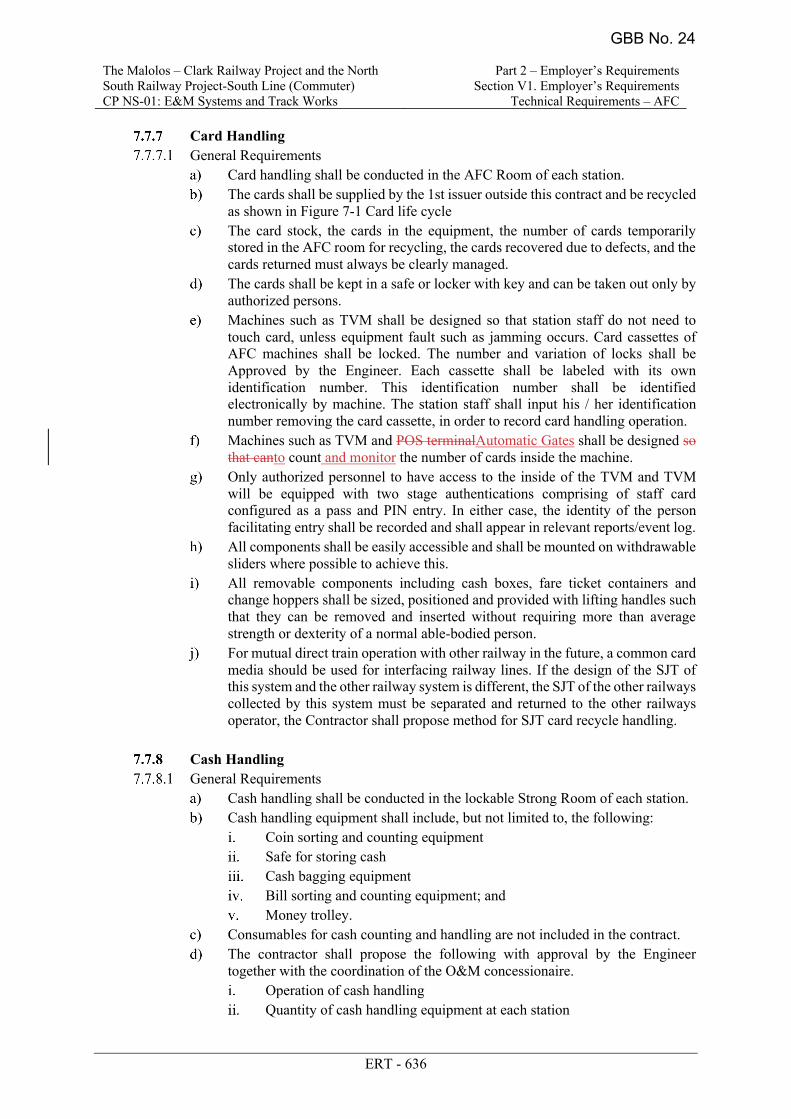
Card Handling General Requirements
Card handling shall be conducted in the AFC Room of each station. The cards shall be supplied by the 1st issuer outside this contract and be recycled
as shown in Figure 7-1 Card life cycle The card stock, the cards in the equipment, the number of cards temporarily
stored in the AFC room for recycling, the cards recovered due to defects, and the cards returned must always be clearly managed.
The cards shall be kept in a safe or locker with key and can be taken out only by authorized persons.
Machines such as TVM shall be designed so that station staff do not need to touch card, unless equipment fault such as jamming occurs. Card cassettes of AFC machines shall be locked. The number and variation of locks shall be Approved by the Engineer. Each cassette shall be labeled with its own identification number. This identification number shall be identified electronically by machine. The station staff shall input his / her identification number removing the card cassette, in order to record card handling operation.
Machines such as TVM and POS terminalAutomatic Gates shall be designed so that canto count and monitor the number of cards inside the machine.
Only authorized personnel to have access to the inside of the TVM and TVM will be equipped with two stage authentications comprising of staff card configured as a pass and PIN entry. In either case, the identity of the person facilitating entry shall be recorded and shall appear in relevant reports/event log.
All components shall be easily accessible and shall be mounted on withdrawable sliders where possible to achieve this.
All removable components including cash boxes, fare ticket containers and change hoppers shall be sized, positioned and provided with lifting handles such that they can be removed and inserted without requiring more than average strength or dexterity of a normal able-bodied person.
For mutual direct train operation with other railway in the future, a common card media should be used for interfacing railway lines. If the design of the SJT of this system and the other railway system is different, the SJT of the other railways collected by this system must be separated and returned to the other railways operator, the Contractor shall propose method for SJT card recycle handling.
Cash Handling
General Requirements Cash handling shall be conducted in the lockable Strong Room of each station. Cash handling equipment shall include, but not limited to, the following:
Coin sorting and counting equipment Safe for storing cash Cash bagging equipment Bill sorting and counting equipment; and Money trolley.
Consumables for cash counting and handling are not included in the contract. The contractor shall propose the following with approval by the Engineer
together with the coordination of the O&M concessionaire. Operation of cash handling Quantity of cash handling equipment at each station
GBB No. 24
The Malolos – Clark Railway Project and the North South Railway Project-South Line (Commuter) CP NS-01: E&M Systems and Track Works
Part 2 – Employer’s Requirements Section V1. Employer’s Requirements
Technical Requirements - Telecommunications
ERT-273
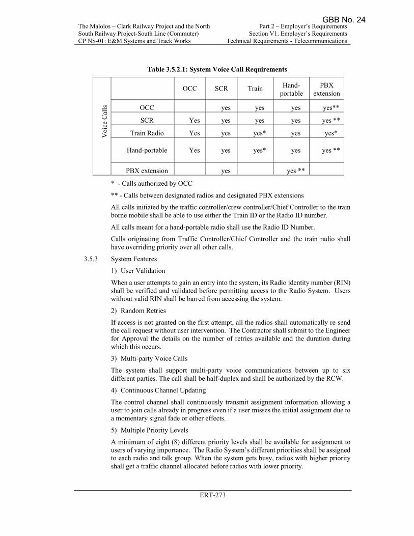
Table 3.5.2.1: System Voice Call Requirements
Voi
ce C
alls
OCC SCR Train Hand-portable
PBX extension
OCC yes yes yes yes**
SCR Yes yes yes yes yes **
Train Radio Yes yes yes* yes yes*
Hand-portable Yes yes yes* yes yes **
PBX extension yes yes **
* - Calls authorized by OCC
** - Calls between designated radios and designated PBX extensions
All calls initiated by the traffic controller/crew controller/Chief Controller to the train borne mobile shall be able to use either the Train ID or the Radio ID number.
All calls meant for a hand-portable radio shall use the Radio ID Number.
Calls originating from Traffic Controller/Chief Controller and the train radio shall have overriding priority over all other calls.
3.5.3 System Features
1) User Validation
When a user attempts to gain an entry into the system, its Radio identity number (RIN) shall be verified and validated before permitting access to the Radio System. Users without valid RIN shall be barred from accessing the system.
2) Random Retries
If access is not granted on the first attempt, all the radios shall automatically re-send the call request without user intervention. The Contractor shall submit to the Engineer for Approval the details on the number of retries available and the duration during which this occurs.
3) Multi-party Voice Calls
The system shall support multi-party voice communications between up to six different parties. The call shall be half-duplex and shall be authorized by the RCW.
4) Continuous Channel Updating
The control channel shall continuously transmit assignment information allowing a user to join calls already in progress even if a user misses the initial assignment due to a momentary signal fade or other effects.
5) Multiple Priority Levels
A minimum of eight (8) different priority levels shall be available for assignment to users of varying importance. The Radio System’s different priorities shall be assigned to each radio and talk group. When the system gets busy, radios with higher priority shall get a traffic channel allocated before radios with lower priority.
GBB No. 24
The Malolos – Clark Railway Project and the North South Railway Project-South Line (Commuter) CP NS-01: E&M Systems and Track Works
Part 2 – Employer’s Requirements Section V1. Employer’s Requirements
Technical Requirements - Telecommunications
ERT-274
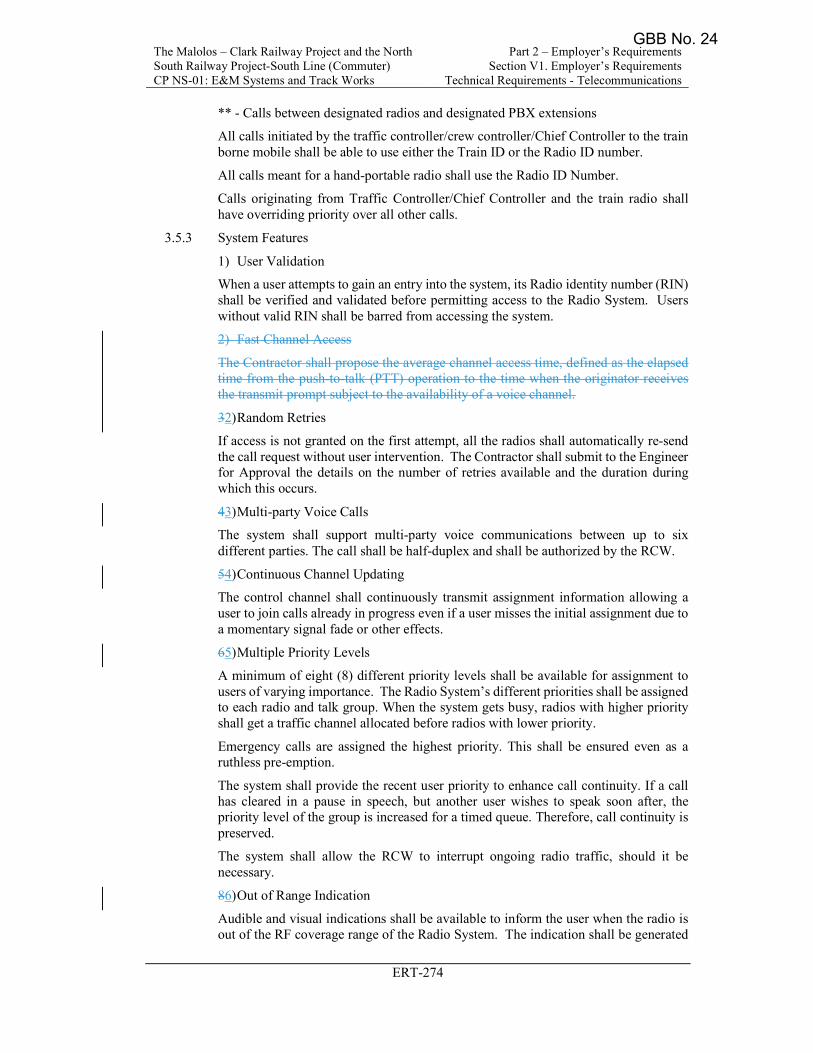
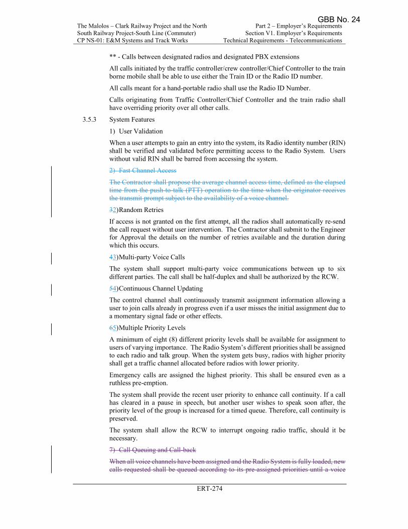
** - Calls between designated radios and designated PBX extensions
All calls initiated by the traffic controller/crew controller/Chief Controller to the train borne mobile shall be able to use either the Train ID or the Radio ID number.
All calls meant for a hand-portable radio shall use the Radio ID Number.
Calls originating from Traffic Controller/Chief Controller and the train radio shall have overriding priority over all other calls.
3.5.3 System Features
1) User Validation
When a user attempts to gain an entry into the system, its Radio identity number (RIN) shall be verified and validated before permitting access to the Radio System. Users without valid RIN shall be barred from accessing the system.
2) Fast Channel Access
The Contractor shall propose the average channel access time, defined as the elapsed time from the push-to-talk (PTT) operation to the time when the originator receives the transmit prompt subject to the availability of a voice channel.
32) Random Retries
If access is not granted on the first attempt, all the radios shall automatically re-send the call request without user intervention. The Contractor shall submit to the Engineer for Approval the details on the number of retries available and the duration during which this occurs.
43) Multi-party Voice Calls
The system shall support multi-party voice communications between up to six different parties. The call shall be half-duplex and shall be authorized by the RCW.
54) Continuous Channel Updating
The control channel shall continuously transmit assignment information allowing a user to join calls already in progress even if a user misses the initial assignment due to a momentary signal fade or other effects.
65) Multiple Priority Levels
A minimum of eight (8) different priority levels shall be available for assignment to users of varying importance. The Radio System’s different priorities shall be assigned to each radio and talk group. When the system gets busy, radios with higher priority shall get a traffic channel allocated before radios with lower priority.
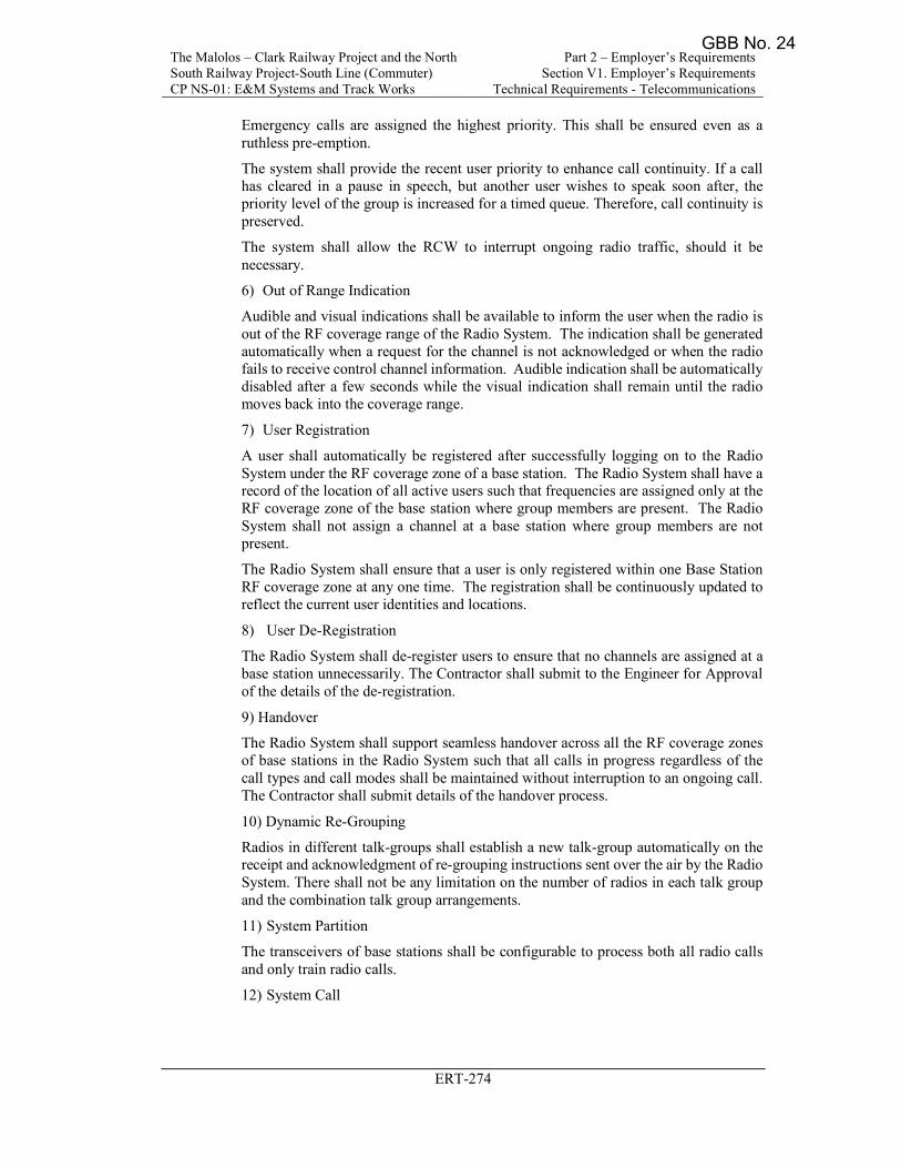
Emergency calls are assigned the highest priority. This shall be ensured even as a ruthless pre-emption.
The system shall provide the recent user priority to enhance call continuity. If a call has cleared in a pause in speech, but another user wishes to speak soon after, the priority level of the group is increased for a timed queue. Therefore, call continuity is preserved.
The system shall allow the RCW to interrupt ongoing radio traffic, should it be necessary.
86) Out of Range Indication
Audible and visual indications shall be available to inform the user when the radio is out of the RF coverage range of the Radio System. The indication shall be generated
GBB No. 24
The Malolos – Clark Railway Project and the North South Railway Project-South Line (Commuter) CP NS-01: E&M Systems and Track Works
Part 2 – Employer’s Requirements Section V1. Employer’s Requirements
Technical Requirements - Telecommunications
ERT-274
Emergency calls are assigned the highest priority. This shall be ensured even as a ruthless pre-emption.
The system shall provide the recent user priority to enhance call continuity. If a call has cleared in a pause in speech, but another user wishes to speak soon after, the priority level of the group is increased for a timed queue. Therefore, call continuity is preserved.
The system shall allow the RCW to interrupt ongoing radio traffic, should it be necessary.
6) Out of Range Indication
Audible and visual indications shall be available to inform the user when the radio is out of the RF coverage range of the Radio System. The indication shall be generated automatically when a request for the channel is not acknowledged or when the radio fails to receive control channel information. Audible indication shall be automatically disabled after a few seconds while the visual indication shall remain until the radio moves back into the coverage range.
7) User Registration
A user shall automatically be registered after successfully logging on to the Radio System under the RF coverage zone of a base station. The Radio System shall have a record of the location of all active users such that frequencies are assigned only at the RF coverage zone of the base station where group members are present. The Radio System shall not assign a channel at a base station where group members are not present.
The Radio System shall ensure that a user is only registered within one Base Station RF coverage zone at any one time. The registration shall be continuously updated to reflect the current user identities and locations.
8) User De-Registration
The Radio System shall de-register users to ensure that no channels are assigned at a base station unnecessarily. The Contractor shall submit to the Engineer for Approval of the details of the de-registration.
9) Handover
The Radio System shall support seamless handover across all the RF coverage zones of base stations in the Radio System such that all calls in progress regardless of the call types and call modes shall be maintained without interruption to an ongoing call. The Contractor shall submit details of the handover process.
10) Dynamic Re-Grouping
Radios in different talk-groups shall establish a new talk-group automatically on the receipt and acknowledgment of re-grouping instructions sent over the air by the Radio System. There shall not be any limitation on the number of radios in each talk group and the combination talk group arrangements.
11) System Partition
The transceivers of base stations shall be configurable to process both all radio calls and only train radio calls.
12) System Call
GBB No. 24
The Malolos – Clark Railway Project and the North South Railway Project-South Line (Commuter) CP NS-01: E&M Systems and Track Works
Part 2 – Employer’s Requirements Section V1. Employer’s Requirements
Technical Requirements - Telecommunications
ERT-274
** - Calls between designated radios and designated PBX extensions
All calls initiated by the traffic controller/crew controller/Chief Controller to the train borne mobile shall be able to use either the Train ID or the Radio ID number.
All calls meant for a hand-portable radio shall use the Radio ID Number.
Calls originating from Traffic Controller/Chief Controller and the train radio shall have overriding priority over all other calls.
3.5.3 System Features
1) User Validation
When a user attempts to gain an entry into the system, its Radio identity number (RIN) shall be verified and validated before permitting access to the Radio System. Users without valid RIN shall be barred from accessing the system.
2) Fast Channel Access
The Contractor shall propose the average channel access time, defined as the elapsed time from the push-to-talk (PTT) operation to the time when the originator receives the transmit prompt subject to the availability of a voice channel.
32) Random Retries
If access is not granted on the first attempt, all the radios shall automatically re-send the call request without user intervention. The Contractor shall submit to the Engineer for Approval the details on the number of retries available and the duration during which this occurs.
43) Multi-party Voice Calls
The system shall support multi-party voice communications between up to six different parties. The call shall be half-duplex and shall be authorized by the RCW.
54) Continuous Channel Updating
The control channel shall continuously transmit assignment information allowing a user to join calls already in progress even if a user misses the initial assignment due to a momentary signal fade or other effects.
65) Multiple Priority Levels
A minimum of eight (8) different priority levels shall be available for assignment to users of varying importance. The Radio System’s different priorities shall be assigned to each radio and talk group. When the system gets busy, radios with higher priority shall get a traffic channel allocated before radios with lower priority.
Emergency calls are assigned the highest priority. This shall be ensured even as a ruthless pre-emption.
The system shall provide the recent user priority to enhance call continuity. If a call has cleared in a pause in speech, but another user wishes to speak soon after, the priority level of the group is increased for a timed queue. Therefore, call continuity is preserved.
The system shall allow the RCW to interrupt ongoing radio traffic, should it be necessary.
7) Call Queuing and Call-back
When all voice channels have been assigned and the Radio System is fully loaded, new calls requested shall be queued according to its pre-assigned priorities until a voice
GBB No. 24

The Malolos – Clark Railway Project and the North South Railway Project-South Line (Commuter) CP NS-01: E&M Systems and Track Works
Part 2 – Employer’s Requirements Section V1. Employer’s Requirements
Technical Requirements - Telecommunications
ERT-276
c) No Reply: Automatically forward the incoming call if there is no reply from the intended recipient; and
d) Not Reachable: Automatically forward the incoming call if the
intended recipient cannot be contacted via the network.
18) Call Hold for Telephone Interconnect Call
The network shall allow the user to temporarily exit from an existing call by putting the call on hold, however, it shall be possible for the user to rejoin the call on hold at any time.
19) Call Waiting for Telephone Interconnect Call
The Radio System shall notify a radio user, who is engaged on an established call, that another call is waiting to be connected.
20) Call Barring
It shall be possible, using a network management system, to prevent individual radio users from making calls to or receiving calls from certain categories of radio users within the network.
3.5.4 Radio Control Workstation (RCW) [Dispatcher] Functionality
3.5.4.1 General
The Contractor shall detail the expansion ability of their RCW Dispatcher network within the switch configuration that has been offered. The radio system shall support a hierarchical dispatcher configuration for the OCC. The higher a particular user is in the hierarchy, the greater their priority within the network.
The RCW shall provide controllers with full functionality with ease of operation and enable reliable communication between users. An unanswered call that has not been acknowledged, shall result in an audible “beep” which shall be made periodically until all calls are acknowledged.
The RCW system shall enable as a minimum the types of the call given below to be initiated by the OCC/Chief Controller/Traffic Controller to the Trains. The Train Controller shall be able to establish these calls without knowing the Radio IDs of the radios involved.
3.5.4.2 RCW Call Features
1) All Trains Calls
Fleet call to all Trains. In a fleet call, the system shall guarantee that the entire fleet is available. Before assigning a channel to a fleet call, the system shall wait for all activity on the users of the communications which comprise the fleet to terminate. As active users end their existing calls, they are in effect put on hold, waiting for the remaining users to become clear. The system will not allow any new calls to be made. When all users are available, the fleet call is granted.
2) Train Group ID Call
The Train Group ID is a Radio ID which will be dynamically allocated by the radio system to a particular group of radios installed on Trains.
The Train Group IDs will also be transparent to all the Train controller operators. During normal operation, there will be no requirement for a Train Controller to utilize any of these IDs in calling a particular Train or group of Trains.
GBB No. 24
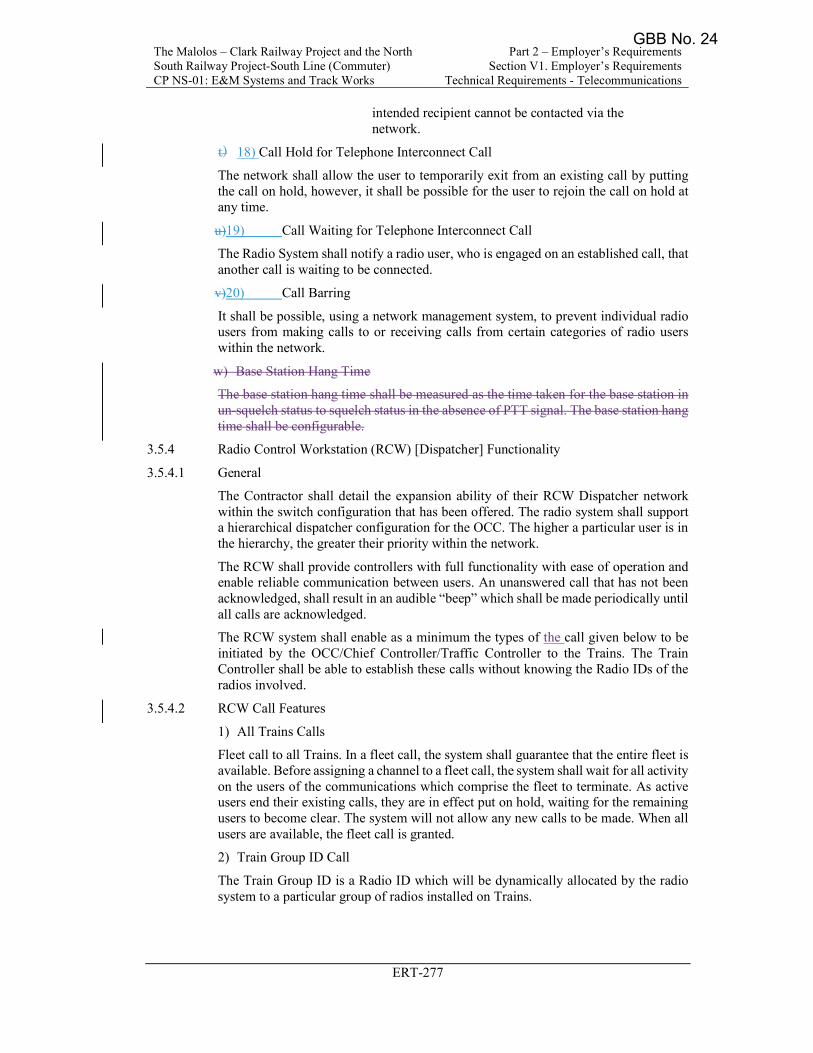
The Malolos – Clark Railway Project and the North South Railway Project-South Line (Commuter) CP NS-01: E&M Systems and Track Works
Part 2 – Employer’s Requirements Section V1. Employer’s Requirements
Technical Requirements - Telecommunications
ERT-277
intended recipient cannot be contacted via the network.
t) 18) Call Hold for Telephone Interconnect Call
The network shall allow the user to temporarily exit from an existing call by putting the call on hold, however, it shall be possible for the user to rejoin the call on hold at any time.
u)19) Call Waiting for Telephone Interconnect Call
The Radio System shall notify a radio user, who is engaged on an established call, that another call is waiting to be connected.
v)20) Call Barring
It shall be possible, using a network management system, to prevent individual radio users from making calls to or receiving calls from certain categories of radio users within the network.
w) Base Station Hang Time
The base station hang time shall be measured as the time taken for the base station in un-squelch status to squelch status in the absence of PTT signal. The base station hang time shall be configurable.
3.5.4 Radio Control Workstation (RCW) [Dispatcher] Functionality
3.5.4.1 General
The Contractor shall detail the expansion ability of their RCW Dispatcher network within the switch configuration that has been offered. The radio system shall support a hierarchical dispatcher configuration for the OCC. The higher a particular user is in the hierarchy, the greater their priority within the network.
The RCW shall provide controllers with full functionality with ease of operation and enable reliable communication between users. An unanswered call that has not been acknowledged, shall result in an audible “beep” which shall be made periodically until all calls are acknowledged.
The RCW system shall enable as a minimum the types of the call given below to be initiated by the OCC/Chief Controller/Traffic Controller to the Trains. The Train Controller shall be able to establish these calls without knowing the Radio IDs of the radios involved.
3.5.4.2 RCW Call Features
1) All Trains Calls
Fleet call to all Trains. In a fleet call, the system shall guarantee that the entire fleet is available. Before assigning a channel to a fleet call, the system shall wait for all activity on the users of the communications which comprise the fleet to terminate. As active users end their existing calls, they are in effect put on hold, waiting for the remaining users to become clear. The system will not allow any new calls to be made. When all users are available, the fleet call is granted.
2) Train Group ID Call
The Train Group ID is a Radio ID which will be dynamically allocated by the radio system to a particular group of radios installed on Trains.
GBB No. 24
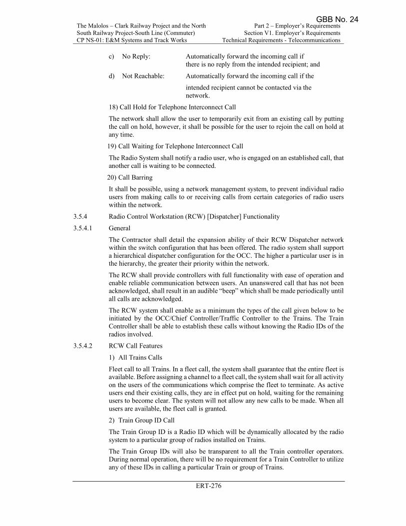
The Malolos – Clark Railway Project and the North South Railway Project-South Line (Commuter) CP NS-01: E&M Systems and Track Works
Part 2 – Employer’s Requirements Section V1. Employer’s Requirements
Technical Requirements - Telecommunications
ERT-276
c) No Reply: Automatically forward the incoming call if there is no reply from the intended recipient; and
d) Not Reachable: Automatically forward the incoming call if the
intended recipient cannot be contacted via the network.
18) Call Hold for Telephone Interconnect Call
The network shall allow the user to temporarily exit from an existing call by putting the call on hold, however, it shall be possible for the user to rejoin the call on hold at any time.
19) Call Waiting for Telephone Interconnect Call
The Radio System shall notify a radio user, who is engaged on an established call, that another call is waiting to be connected.
20) Call Barring
It shall be possible, using a network management system, to prevent individual radio users from making calls to or receiving calls from certain categories of radio users within the network.
3.5.4 Radio Control Workstation (RCW) [Dispatcher] Functionality
3.5.4.1 General
The Contractor shall detail the expansion ability of their RCW Dispatcher network within the switch configuration that has been offered. The radio system shall support a hierarchical dispatcher configuration for the OCC. The higher a particular user is in the hierarchy, the greater their priority within the network.
The RCW shall provide controllers with full functionality with ease of operation and enable reliable communication between users. An unanswered call that has not been acknowledged, shall result in an audible “beep” which shall be made periodically until all calls are acknowledged.
The RCW system shall enable as a minimum the types of the call given below to be initiated by the OCC/Chief Controller/Traffic Controller to the Trains. The Train Controller shall be able to establish these calls without knowing the Radio IDs of the radios involved.
3.5.4.2 RCW Call Features
1) All Trains Calls
Fleet call to all Trains. In a fleet call, the system shall guarantee that the entire fleet is available. Before assigning a channel to a fleet call, the system shall wait for all activity on the users of the communications which comprise the fleet to terminate. As active users end their existing calls, they are in effect put on hold, waiting for the remaining users to become clear. The system will not allow any new calls to be made. When all users are available, the fleet call is granted.
2) Train Group ID Call
The Train Group ID is a Radio ID which will be dynamically allocated by the radio system to a particular group of radios installed on Trains.
The Train Group IDs will also be transparent to all the Train controller operators. During normal operation, there will be no requirement for a Train Controller to utilize any of these IDs in calling a particular Train or group of Trains.
GBB No. 24
The Malolos – Clark Railway Project and the North South Railway Project-South Line (Commuter) CP NS-01: E&M Systems and Track Works
Part 2 – Employer’s Requirements Section V1. Employer’s Requirements
Technical Requirements - Telecommunications
ERT-277
intended recipient cannot be contacted via the network.
t) 18) Call Hold for Telephone Interconnect Call
The network shall allow the user to temporarily exit from an existing call by putting the call on hold, however, it shall be possible for the user to rejoin the call on hold at any time.
u)19) Call Waiting for Telephone Interconnect Call
The Radio System shall notify a radio user, who is engaged on an established call, that another call is waiting to be connected.
v)20) Call Barring
It shall be possible, using a network management system, to prevent individual radio users from making calls to or receiving calls from certain categories of radio users within the network.
w) Preferred Control Channel
All radios shall remain affiliate to a preferred control channel of a designated base station if the signal strength is at an acceptable level in all circumstances including the base station in local trunking mode.
When the preferred control channel signal strength falls below the acceptable level, the radio shall affiliate to another control channel with an acceptable signal level.
3.5.4 Radio Control Workstation (RCW) [Dispatcher] Functionality
3.5.4.1 General
The Contractor shall detail the expansion ability of their RCW Dispatcher network within the switch configuration that has been offered. The radio system shall support a hierarchical dispatcher configuration for the OCC. The higher a particular user is in the hierarchy, the greater their priority within the network.
The RCW shall provide controllers with full functionality with ease of operation and enable reliable communication between users. An unanswered call that has not been acknowledged, shall result in an audible “beep” which shall be made periodically until all calls are acknowledged.
The RCW system shall enable as a minimum the types of the call given below to be initiated by the OCC/Chief Controller/Traffic Controller to the Trains. The Train Controller shall be able to establish these calls without knowing the Radio IDs of the radios involved.
3.5.4.2 RCW Call Features
1) All Trains Calls
Fleet call to all Trains. In a fleet call, the system shall guarantee that the entire fleet is available. Before assigning a channel to a fleet call, the system shall wait for all activity on the users of the communications which comprise the fleet to terminate. As active users end their existing calls, they are in effect put on hold, waiting for the remaining users to become clear. The system will not allow any new calls to be made. When all users are available, the fleet call is granted.
2) Train Group ID Call
The Train Group ID is a Radio ID which will be dynamically allocated by the radio system to a particular group of radios installed on Trains.
GBB No. 24

The Malolos – Clark Railway Project and the North South Railway Project-South Line (Commuter) CP NS-01: E&M Systems and Track Works
Part 2 – Employer’s Requirements Section V1. Employer’s Requirements
Technical Requirements - Telecommunications
ERT-279
A pop-up window with visual and audible alert shall show details of the Train ID and location from which a priority call was originated when there is an incoming “High Priority” call. The controller shall be able to acknowledge the call and then select to activate two-way communication.
12) Call Inclusion
The Traffic Controller shall be able to perform 'Call Inclusion' to participate in active calls, allowing the use of pre-emption and a forced call clearing capability.
13) Group Patching
The Controller shall be able to perform Group Patching to handle call authorization for specific types of calls and/or specific users.
The RCW shall be able to pre-store configurations of the Patch groups. These shall be preferably stored in folders represented on the desktop. The controller shall be able to click on one of the patch folders to bring that folder forward.
The Controller shall be able to modify the members of the Patch groups by bringing the folder forward; clicking on the Patch Edit button and adding members to the group. Members may be removed from the group by clicking again on an "unselect" option.
The Controller shall be able to perform Dynamic Regrouping for modification of Individual and Group priorities.
The Controller shall be able to regroup the talk-groups dynamically to allow flexible and versatile group communication. Group call shall be on an “Everyone hears Everyone” basis in line with traditional open channels. Group call communication shall be achieved by pressing a PTT switch following the selection of the group.
14) Calling Party Identification
The RCW shall include Calling Line Identification to display the calling user identification and which Radio Base Station is used.
The RCW shall include Connected Line Identification to display the called user identification for Telephone Interconnect Call.
15) Hold Function for Telephone Interconnect Call
The RCW shall allow a call Hold function.
16) Call Forwarding for Telephone Interconnect Call
The RCW shall allow Call Forwarding to another Controller if a controller is busy or does not reply with a predefined period.
17) Train Radio Status Call
The train driver shall be able to send pre-defined status messages to the OCC Traffic Controller. The System shall support a minimum of 64 Status messages. The status messages shall be proposed by the Contractor.
18) RCW-ICONS Toolbar
A toolbar is a row of icon buttons at the top of the screen to perform all the RCW call functions shall be provided and shall also include the following buttons. The finalized identification and wording of the buttons shall be given a Notice of No Objection by the Engineer. As a minimum these shall include the following:
a) All Mute;
b) Monitor;
GBB No. 24
The Malolos – Clark Railway Project and the North South Railway Project-South Line (Commuter) CP NS-01: E&M Systems and Track Works
Part 2 – Employer’s Requirements Section V1. Employer’s Requirements
Technical Requirements - Telecommunications
ERT-280
The Controller shall be able to acknowledge an emergency call by pressing a predefined key on the RCW keyboard. An emergency call from a train shall have the highest priority available within the network.
A pop-up window scroll bar shall be displayed with visual and audible alerts showing detail of the Train ID location from which the emergency call originated.
The Controller shall be able to acknowledge the call and then select the calling train to activate two-way communication. If such a call is not answered within a pre-defined number of seconds the call shall be transferred automatically to another designated controller.
11) Priority Alert Call
A pop-up window with visual and audible alert shall show details of the Train ID and location from which a priority call was originated when there is an incoming “High Priority” call. The controller shall be able to acknowledge the call and then select to activate two-way communication.
12) Call Inclusion
The Traffic Controller shall be able to perform 'Call Inclusion' to participate in active calls, allowing the use of pre-emption and a forced call clearing capability.
13) Group Patching
The Controller shall be able to perform Group Patching to handle call authorization for specific types of calls and/or specific users.
The RCW shall be able to pre-store configurations of the Patch groups. These shall be preferably stored in folders represented on the desktop. The controller shall be able to click on one of the patch folders to bring that folder forward.
The Controller shall be able to modify the members of the Patch groups by bringing the folder forward; clicking on the Patch Edit button and adding members to the group. Members may be removed from the group by clicking again on an "unselect" option.
The Controller shall be able to perform Dynamic Regrouping for modification of Individual and Group priorities.
The Controller shall be able to regroup the talk-groups dynamically to allow flexible and versatile group communication. Group call shall be on an “Everyone hears Everyone” basis in line with traditional open channels. Group call communication shall be achieved by pressing a PTT switch following the selection of the group.
14) Calling Party Identification
The RCW shall include Calling Line Identification to display the calling user identification and which Radio Base Station is used.
The RCW shall include Connected Line Identification to display the called user identification for Telephone Interconnect Call.
15) Late Entry Facility
Late Entry Facility shall be provided for users that are busy or unavailable at the time a group call is established. They shall be invited to join in the call at regular intervals for the duration of that call.
165) Hold Function for Telephone Interconnect Call
The RCW shall allow a call Hold function.
GBB No. 24
The Malolos – Clark Railway Project and the North South Railway Project-South Line (Commuter) CP NS-01: E&M Systems and Track Works
Part 2 – Employer’s Requirements Section V1. Employer’s Requirements
Technical Requirements - Telecommunications
ERT-279
A pop-up window with visual and audible alert shall show details of the Train ID and location from which a priority call was originated when there is an incoming “High Priority” call. The controller shall be able to acknowledge the call and then select to activate two-way communication.
12) Call Inclusion
The Traffic Controller shall be able to perform 'Call Inclusion' to participate in active calls, allowing the use of pre-emption and a forced call clearing capability.
13) Group Patching
The Controller shall be able to perform Group Patching to handle call authorization for specific types of calls and/or specific users.
The RCW shall be able to pre-store configurations of the Patch groups. These shall be preferably stored in folders represented on the desktop. The controller shall be able to click on one of the patch folders to bring that folder forward.
The Controller shall be able to modify the members of the Patch groups by bringing the folder forward; clicking on the Patch Edit button and adding members to the group. Members may be removed from the group by clicking again on an "unselect" option.
The Controller shall be able to perform Dynamic Regrouping for modification of Individual and Group priorities.
The Controller shall be able to regroup the talk-groups dynamically to allow flexible and versatile group communication. Group call shall be on an “Everyone hears Everyone” basis in line with traditional open channels. Group call communication shall be achieved by pressing a PTT switch following the selection of the group.
14) Calling Party Identification
The RCW shall include Calling Line Identification to display the calling user identification and which Radio Base Station is used.
The RCW shall include Connected Line Identification to display the called user identification for Telephone Interconnect Call.
15) Hold Function for Telephone Interconnect Call
The RCW shall allow a call Hold function.
16) Call Forwarding for Telephone Interconnect Call
The RCW shall allow Call Forwarding to another Controller if a controller is busy or does not reply with a predefined period.
17) Train Radio Status Call
The train driver shall be able to send pre-defined status messages to the OCC Traffic Controller. The System shall support a minimum of 64 Status messages. The status messages shall be proposed by the Contractor.
18) RCW-ICONS Toolbar
A toolbar is a row of icon buttons at the top of the screen to perform all the RCW call functions shall be provided and shall also include the following buttons. The finalized identification and wording of the buttons shall be given a Notice of No Objection by the Engineer. As a minimum these shall include the following:
a) All Mute;
b) Monitor;
GBB No. 24
The Malolos – Clark Railway Project and the North South Railway Project-South Line (Commuter) CP NS-01: E&M Systems and Track Works
Part 2 – Employer’s Requirements Section V1. Employer’s Requirements
Technical Requirements - Telecommunications
ERT-281
1716) Call Forwarding for Telephone Interconnect Call
The RCW shall allow Call Forwarding to another Controller if a controller is busy or does not reply with a predefined period.
18) Remote Radio Activation
The Controller shall be able to remotely switch on the microphone and transmitter of the Train radio or Hand-portable and listen to the received audio.
197) Train Radio Status Call
The train driver shall be able to send pre-defined status messages to the OCC Traffic Controller. The System shall support a minimum of 64 Status messages. The status messages shall be proposed by the Contractor.
1821) RCW-ICONS Toolbar
A toolbar is a row of icon buttons at the top of the screen to perform all the RCW call functions shall be provided and shall also include the following buttons. The finalized identification and wording of the buttons shall be given a Notice of No Objection by the Engineer. As a minimum these shall include the following:
a) All Mute;
b) Monitor;
c) Transmit;
d) Telephone Dialer;
e) View; and
f) Time Out.
2219) RCW Side menu
A side menu panel shall be provided on the display to allow the type of call to be selected such as free form PA, pre-set PA messages (digital voice stored on the DVA), normal voice, status, priority, or emergency calls.
2320) RCW Window templates
The Controller shall be able to set up individual user screen configurations, i.e. different controller window templates. The terminal shall save and recall up to eight different user-defined screen layouts, allowing different controllers to quickly call up preference files based on the log-in role of the controller.
The RCW shall allow different configurations of built-in help functions, designed to assist the controller.
2421) RCW Log-on Facilities
The RCW shall incorporate Access Control features and bring up a password-protected Log-on dialogue box to provide access control and security and validation of access permissions when the system is switched on so that the RCW is set to the default condition for all available buttons and actions.
A password-protected exit dialogue box shall be provided and be activated when the exit button is pressed to ensure that the user wants to exit the system.
It should be possible to take over control of another RCW while also retaining its own RCW’s control. On taking over control calls should be routed to both the RCWs.
GBB No. 24
The Malolos – Clark Railway Project and the North South Railway Project-South Line (Commuter) CP NS-01: E&M Systems and Track Works
Part 2 – Employer’s Requirements Section V1. Employer’s Requirements
Technical Requirements - Telecommunications
ERT-280
c) Transmit;
d) Telephone Dialer;
e) View; and
f) Time Out.
19) RCW Side menu
A side menu panel shall be provided on the display to allow the type of call to be selected such as free form PA, pre-set PA messages (digital voice stored on the DVA), normal voice, status, priority, or emergency calls.
20) RCW Window templates
The Controller shall be able to set up individual user screen configurations, i.e. different controller window templates. The terminal shall save and recall up to eight different user-defined screen layouts, allowing different controllers to quickly call up preference files based on the log-in role of the controller.
The RCW shall allow different configurations of built-in help functions, designed to assist the controller.
21) RCW Log-on Facilities
The RCW shall incorporate Access Control features and bring up a password-protected Log-on dialogue box to provide access control and security and validation of access permissions when the system is switched on so that the RCW is set to the default condition for all available buttons and actions.
A password-protected exit dialogue box shall be provided and be activated when the exit button is pressed to ensure that the user wants to exit the system.
It should be possible to take over control of another RCW while also retaining its own RCW’s control. On taking over control calls should be routed to both the RCWs.
22) RCW Display
The RCW screen display shall be designed to be uncluttered, well-labeled, and logically arranged for ease of use to help the OCC controllers to respond instantly, even during emergencies.
The RCW display shall include the display of a 24-hour format clock in the top right-hand corner of the screen.
3.5.5 Train Radio Operation
The Contractor shall be responsible for the design/application engineering, retrofitting, supervision, testing, and commissioning of the complete Train-borne Radio Communications System.
The Complete Train Radio System shall be installed in both the leading and trailing cabs operating in hot-standby mode to each other but shall be fully independent of each other. The Contractor shall use the train line between the front and rear cabs, for the Train Radio hot standby features. The Train Radio along with TR-HMI, TRIU, etc. shall be provided in the Rolling Stock. Therefore, the physical dimensions, positions, mounting holes, antenna type, cable routes, cable lengths, cable/pin connections to the Rolling Stock PA/TMS systems, protocols, exact data to be exchanged, etc. are to be interface with the Contractor. The Train Radio Interfacing Unit shall monitor the health of the radio transceivers and all other data interfaces to the train-borne Signaling
GBB No. 24
The Malolos – Clark Railway Project and the North South Railway Project-South Line (Commuter) CP NS-01: E&M Systems and Track Works
Part 2 – Employer’s Requirements Section V1. Employer’s Requirements
Technical Requirements - Telecommunications
ERT-281
1716) Call Forwarding for Telephone Interconnect Call
The RCW shall allow Call Forwarding to another Controller if a controller is busy or does not reply with a predefined period.
197) Train Radio Status Call
The train driver shall be able to send pre-defined status messages to the OCC Traffic Controller. The System shall support a minimum of 64 Status messages. The status messages shall be proposed by the Contractor.
20) Dynamic Time-out Disable
In emergencies, the system shall be able to cancel the dynamic time out feature on the radio base station.
1821) RCW-ICONS Toolbar
A toolbar is a row of icon buttons at the top of the screen to perform all the RCW call functions shall be provided and shall also include the following buttons. The finalized identification and wording of the buttons shall be given a Notice of No Objection by the Engineer. As a minimum these shall include the following:
a) All Mute;
b) Monitor;
c) Transmit;
d) Telephone Dialer;
e) View; and
f) Time Out.
2219) RCW Side menu
A side menu panel shall be provided on the display to allow the type of call to be selected such as free form PA, pre-set PA messages (digital voice stored on the DVA), normal voice, status, priority, or emergency calls.
2320) RCW Window templates
The Controller shall be able to set up individual user screen configurations, i.e. different controller window templates. The terminal shall save and recall up to eight different user-defined screen layouts, allowing different controllers to quickly call up preference files based on the log-in role of the controller.
The RCW shall allow different configurations of built-in help functions, designed to assist the controller.
2421) RCW Log-on Facilities
The RCW shall incorporate Access Control features and bring up a password-protected Log-on dialogue box to provide access control and security and validation of access permissions when the system is switched on so that the RCW is set to the default condition for all available buttons and actions.
A password-protected exit dialogue box shall be provided and be activated when the exit button is pressed to ensure that the user wants to exit the system.
It should be possible to take over control of another RCW while also retaining its own RCW’s control. On taking over control calls should be routed to both the RCWs.
GBB No. 24
The Malolos – Clark Railway Project and the North South Railway Project-South Line (Commuter) CP NS-01: E&M Systems and Track Works
Part 2 – Employer’s Requirements Section V1. Employer’s Requirements
Technical Requirements - Telecommunications
ERT-272
speak at any one time. It shall, however, be possible for a Controller to interrupt the talking member. These calls shall be half-duplex and shall be permitted to all users.
3) Broadcast call
The broadcast call shall be a one-way call from a single user to all users of the same call group within a pre-defined area. Only the OCC shall be permitted to initiate a broadcast call.
4) Data Call:
The System shall support the following:
a) Unprotected data
b) Protected data
c) Pre-formatted/pre-defined text status messages from the train radio, hand-portable radios, or the OCC.
d) The system shall have the facility of transferring data from the train to the OCC.
The system should be supplied with a Packet Data Gateway (PDG) as per ETSI or equivalent standards/guidelines. External access to the Radio System through the PDG shall be firewall protected.
5) Emergency Call
Train-borne mobile, hand-portables, and the Operation Control Center (OCC) shall be permitted to initiate emergency calls. There shall be two types of emergency calls:
a) Train Emergency call: The train emergency call shall be automatically routed to the designated jurisdiction control Traffic Controller; and
b) Shunting emergency call: The Shunting emergency call shall be sent to all users involved in shunting operations.
The radio shall periodically check the availability of a base station. Once a base station is detected again, the radio shall switch back to the normal mode of operation.
The user shall be informed by visual and audible alarms.
This feature might not apply to all users and therefore shall be configurable by the administrator of the system.
The Contractor shall propose the details of the preferred backup mode of operation.
6) Train PA Call
It shall be possible for the OCC to access the Train-borne PA system and make pre-recorded or live announcements to individual trains, a group of trains, or all trains in a section.
7) System Call Requirements
A minimum of eight (8) priority levels shall be available for assignment to radio users of varying importance. Priority-setting shall be configurable from the central control.
The Radio System shall as minimum support the communication between various parties by the following matrix:
GBB No. 24
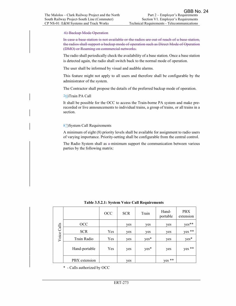
The Malolos – Clark Railway Project and the North South Railway Project-South Line (Commuter) CP NS-01: E&M Systems and Track Works
Part 2 – Employer’s Requirements Section V1. Employer’s Requirements
Technical Requirements - Telecommunications
ERT-273
6) Backup Mode Operation
In case a base station is not available or the radios are out of reach of a base station, the radios shall support a backup mode of operation such as Direct Mode of Operation (DMO) or Roaming on commercial networks.
The radio shall periodically check the availability of a base station. Once a base station is detected again, the radio shall switch back to the normal mode of operation.
The user shall be informed by visual and audible alarms.
This feature might not apply to all users and therefore shall be configurable by the administrator of the system.
The Contractor shall propose the details of the preferred backup mode of operation.
76) Train PA Call
It shall be possible for the OCC to access the Train-borne PA system and make pre-recorded or live announcements to individual trains, a group of trains, or all trains in a section.
87) System Call Requirements
A minimum of eight (8) priority levels shall be available for assignment to radio users of varying importance. Priority-setting shall be configurable from the central control.
The Radio System shall as a minimum support the communication between various parties by the following matrix:
Table 3.5.2.1: System Voice Call Requirements
Voi
ce C
alls
OCC SCR Train Hand-portable
PBX extension
OCC yes yes yes yes**
SCR Yes yes yes yes yes **
Train Radio Yes yes yes* yes yes*
Hand-portable Yes yes yes* yes yes **
PBX extension yes yes **
* - Calls authorized by OCC
GBB No. 24
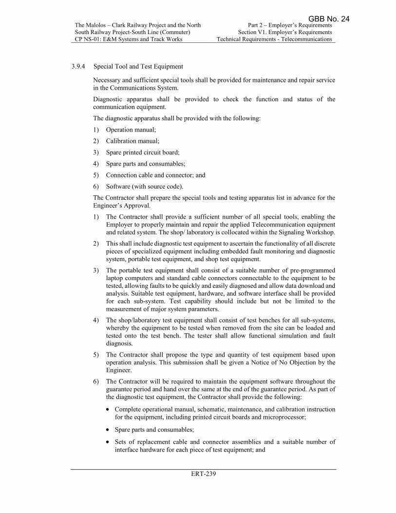
The Malolos – Clark Railway Project and the North South Railway Project-South Line (Commuter) CP NS-01: E&M Systems and Track Works
Part 2 – Employer’s Requirements Section V1. Employer’s Requirements
Technical Requirements - Telecommunications
ERT-239
3.9.4 Special Tool and Test Equipment
Necessary and sufficient special tools shall be provided for maintenance and repair service in the Communications System.
Diagnostic apparatus shall be provided to check the function and status of the communication equipment.
The diagnostic apparatus shall be provided with the following:
1) Operation manual;
2) Calibration manual;
3) Spare printed circuit board;
4) Spare parts and consumables;
5) Connection cable and connector; and
6) Software (with source code).
The Contractor shall prepare the special tools and testing apparatus list in advance for the Engineer’s Approval.
1) The Contractor shall provide a sufficient number of all special tools, enabling the Employer to properly maintain and repair the applied Telecommunication equipment and related system. The shop/ laboratory is collocated within the Signaling Workshop.
2) This shall include diagnostic test equipment to ascertain the functionality of all discrete pieces of specialized equipment including embedded fault monitoring and diagnostic system, portable test equipment, and shop test equipment.
3) The portable test equipment shall consist of a suitable number of pre-programmed laptop computers and standard cable connectors connectable to the equipment to be tested, allowing faults to be quickly and easily diagnosed and allow data download and analysis. Suitable test equipment, hardware, and software interface shall be provided for each sub-system. Test capability should include but not be limited to the measurement of major system parameters.
4) The shop/laboratory test equipment shall consist of test benches for all sub-systems, whereby the equipment to be tested when removed from the site can be loaded and tested onto the test bench. The tester shall allow functional simulation and fault diagnosis.
5) The Contractor shall propose the type and quantity of test equipment based upon operation analysis. This submission shall be given a Notice of No Objection by the Engineer.
6) The Contractor will be required to maintain the equipment software throughout the guarantee period and hand over the same at the end of the guarantee period. As part of the diagnostic test equipment, the Contractor shall provide the following:
Complete operational manual, schematic, maintenance, and calibration instruction for the equipment, including printed circuit boards and microprocessor;
Spare parts and consumables;
Sets of replacement cable and connector assemblies and a suitable number of interface hardware for each piece of test equipment; and
GBB No. 24
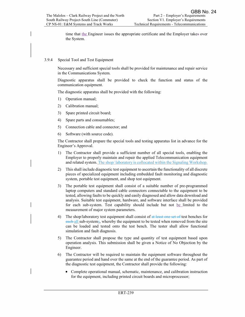
The Malolos – Clark Railway Project and the North South Railway Project-South Line (Commuter) CP NS-01: E&M Systems and Track Works
Part 2 – Employer’s Requirements Section V1. Employer’s Requirements
Technical Requirements - Telecommunications
ERT-239
time that the Engineer issues the appropriate certificate and the Employer takes over the System.
3.9.4 Special Tool and Test Equipment
Necessary and sufficient special tools shall be provided for maintenance and repair service in the Communications System.
Diagnostic apparatus shall be provided to check the function and status of the communication equipment.
The diagnostic apparatus shall be provided with the following:
1) Operation manual;
2) Calibration manual;
3) Spare printed circuit board;
4) Spare parts and consumables;
5) Connection cable and connector; and
6) Software (with source code).
The Contractor shall prepare the special tools and testing apparatus list in advance for the Engineer’s Approval.
1) The Contractor shall provide a sufficient number of all special tools, enabling the Employer to properly maintain and repair the applied Telecommunication equipment and related system. The shop/ laboratory is collocated within the Signaling Workshop.
2) This shall include diagnostic test equipment to ascertain the functionality of all discrete pieces of specialized equipment including embedded fault monitoring and diagnostic system, portable test equipment, and shop test equipment.
3) The portable test equipment shall consist of a suitable number of pre-programmed laptop computers and standard cable connectors connectable to the equipment to be tested, allowing faults to be quickly and easily diagnosed and allow data download and analysis. Suitable test equipment, hardware, and software interface shall be provided for each sub-system. Test capability should include but not be limited to the measurement of major system parameters.
4) The shop/laboratory test equipment shall consist of at least one set of test benches for each all sub-systems, whereby the equipment to be tested when removed from the site can be loaded and tested onto the test bench. The tester shall allow functional simulation and fault diagnosis.
5) The Contractor shall propose the type and quantity of test equipment based upon operation analysis. This submission shall be given a Notice of No Objection by the Engineer.
6) The Contractor will be required to maintain the equipment software throughout the guarantee period and hand over the same at the end of the guarantee period. As part of the diagnostic test equipment, the Contractor shall provide the following:
Complete operational manual, schematic, maintenance, and calibration instruction for the equipment, including printed circuit boards and microprocessor;
GBB No. 24
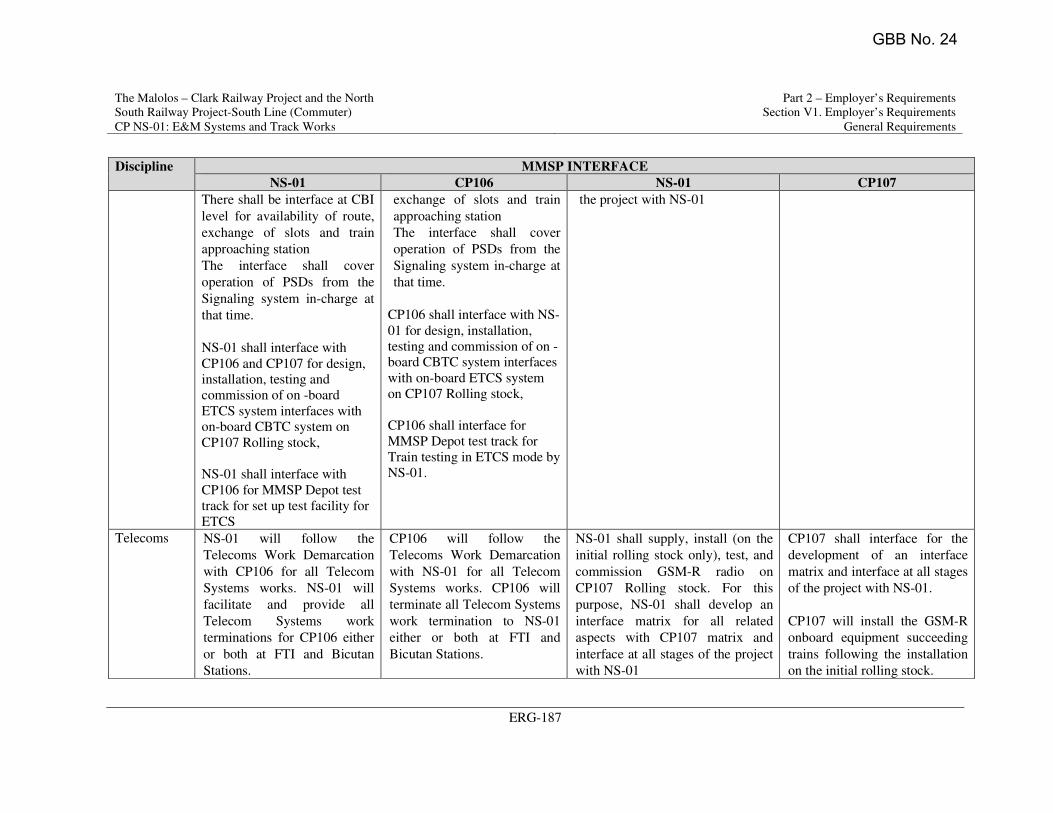
The Malolos – Clark Railway Project and the North
South Railway Project-South Line (Commuter)
CP NS-01: E&M Systems and Track Works
Part 2 – Employer’s Requirements
Section V1. Employer’s Requirements
General Requirements
ERG-187
Discipline MMSP INTERFACE
NS-01 CP106 NS-01 CP107
There shall be interface at CBI
level for availability of route,
exchange of slots and train
approaching station
The interface shall cover
operation of PSDs from the
Signaling system in-charge at
that time.
NS-01 shall interface with
CP106 and CP107 for design,
installation, testing and
commission of on -board
ETCS system interfaces with
on-board CBTC system on
CP107 Rolling stock,
NS-01 shall interface with
CP106 for MMSP Depot test
track for set up test facility for
ETCS
exchange of slots and train
approaching station
The interface shall cover
operation of PSDs from the
Signaling system in-charge at
that time.
CP106 shall interface with NS-
01 for design, installation,
testing and commission of on -
board CBTC system interfaces
with on-board ETCS system
on CP107 Rolling stock,
CP106 shall interface for
MMSP Depot test track for
Train testing in ETCS mode by
NS-01.
the project with NS-01
Telecoms NS-01 will follow the
Telecoms Work Demarcation
with CP106 for all Telecom
Systems works. NS-01 will
facilitate and provide all
Telecom Systems work
terminations for CP106 either
or both at FTI and Bicutan
Stations.
CP106 will follow the
Telecoms Work Demarcation
with NS-01 for all Telecom
Systems works. CP106 will
terminate all Telecom Systems
work termination to NS-01
either or both at FTI and
Bicutan Stations.
NS-01 shall supply, install (on the
initial rolling stock only), test, and
commission GSM-R radio on
CP107 Rolling stock. For this
purpose, NS-01 shall develop an
interface matrix for all related
aspects with CP107 matrix and
interface at all stages of the project
with NS-01
CP107 shall interface for the
development of an interface
matrix and interface at all stages
of the project with NS-01.
CP107 will install the GSM-R
onboard equipment succeeding
trains following the installation
on the initial rolling stock.
GBB No. 24
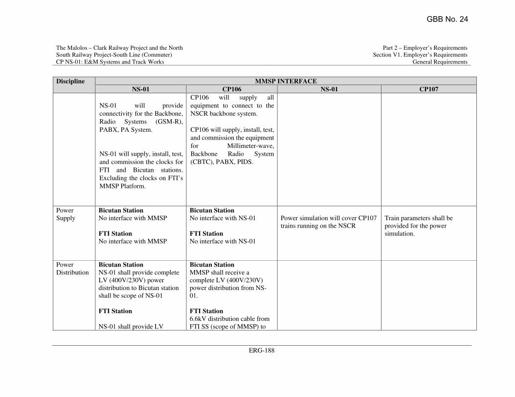
The Malolos – Clark Railway Project and the North
South Railway Project-South Line (Commuter)
CP NS-01: E&M Systems and Track Works
Part 2 – Employer’s Requirements
Section V1. Employer’s Requirements
General Requirements
ERG-188
Discipline MMSP INTERFACE
NS-01 CP106 NS-01 CP107
NS-01 will provide
connectivity for the Backbone,
Radio Systems (GSM-R),
PABX, PA System.
NS-01 will supply, install, test,
and commission the clocks for
FTI and Bicutan stations.
Excluding the clocks on FTI’s
MMSP Platform.
CP106 will supply all
equipment to connect to the
NSCR backbone system.
CP106 will supply, install, test,
and commission the equipment
for Millimeter-wave,
Backbone Radio System
(CBTC), PABX, PIDS.
Power
Supply
Bicutan Station
No interface with MMSP
FTI Station
No interface with MMSP
Bicutan Station
No interface with NS-01
FTI Station
No interface with NS-01
Power simulation will cover CP107
trains running on the NSCR
Train parameters shall be
provided for the power
simulation.
Power
Distribution
Bicutan Station
NS-01 shall provide complete
LV (400V/230V) power
distribution to Bicutan station
shall be scope of NS-01
FTI Station
NS-01 shall provide LV
Bicutan Station
MMSP shall receive a
complete LV (400V/230V)
power distribution from NS-
01.
FTI Station
6.6kV distribution cable from
FTI SS (scope of MMSP) to
GBB No. 24
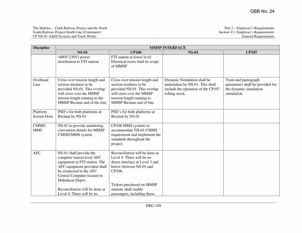
The Malolos – Clark Railway Project and the North
South Railway Project-South Line (Commuter)
CP NS-01: E&M Systems and Track Works
Part 2 – Employer’s Requirements
Section V1. Employer’s Requirements
General Requirements
ERG-189
Discipline MMSP INTERFACE
NS-01 CP106 NS-01 CP107
(400V/230V) power
distribution to FTI station. .
FTI station at lower level
Electrical room shall be scope
of MMSP
Overhead
Line
Cross over tension length and
section insulator to be
provided NS-01. This overlap
will cross over the MMSP
tension length running to the
MMSP Bicutan end of the line.
Cross over tension length and
section insulator to be
provided NS-01. This overlap
will cross over the MMSP
tension length running to
MMSP Bicutan end of line
Dynamic Simulation shall be
undertaken by NS-01. This shall
include the operation of the CP107
rolling stock,
Train and pantograph
parameters shall be provided for
the dynamic simulation
simulation.
Platform
Screen Door
PSD’s for both platforms at
Bicutan by NS-01
PSD’s for both platforms at
Bicutan by NS-01
CMMS/
MMS
NS-01 to provide numbering
convention details for MMSP
CMMS/MMS system.
CP106 MMS systems to
accommodate NS-01 CMMS
requirement and implement the
standards throughout the
project.
AFC NS-01 shall provide the
complete station level AFC
equipment in FTI station. The
AFC equipment provided shall
be connected to the AFC
Central Computer located in
Mabalacat Depot.
Reconciliation will be done at
Level 4. There will be no
Reconciliation will be done at
Level 4. There will be no
direct interface at Level 3 and
below between NS-01 and
CP106.
Tickets purchased on MMSP
stations shall enable
passengers, including those
GBB No. 24
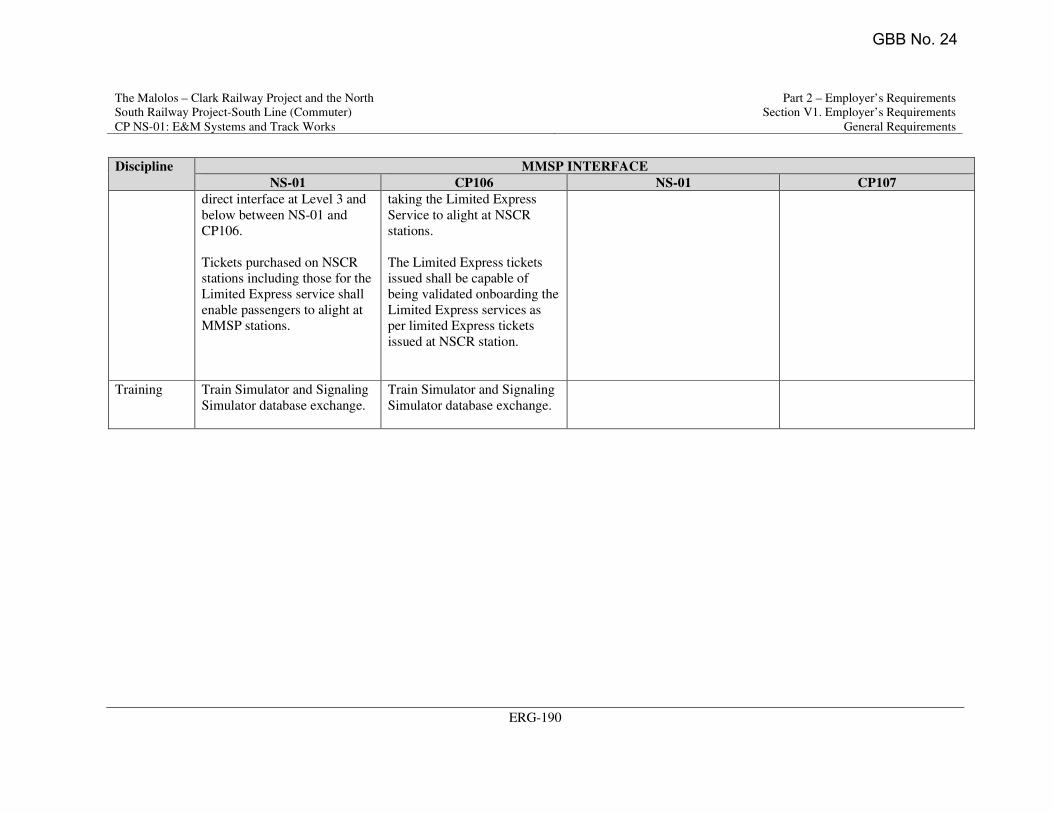
The Malolos – Clark Railway Project and the North
South Railway Project-South Line (Commuter)
CP NS-01: E&M Systems and Track Works
Part 2 – Employer’s Requirements
Section V1. Employer’s Requirements
General Requirements
ERG-190
Discipline MMSP INTERFACE
NS-01 CP106 NS-01 CP107
direct interface at Level 3 and
below between NS-01 and
CP106.
Tickets purchased on NSCR
stations including those for the
Limited Express service shall
enable passengers to alight at
MMSP stations.
taking the Limited Express
Service to alight at NSCR
stations.
The Limited Express tickets
issued shall be capable of
being validated onboarding the
Limited Express services as
per limited Express tickets
issued at NSCR station.
Training Train Simulator and Signaling
Simulator database exchange.
Train Simulator and Signaling
Simulator database exchange.
GBB No. 24
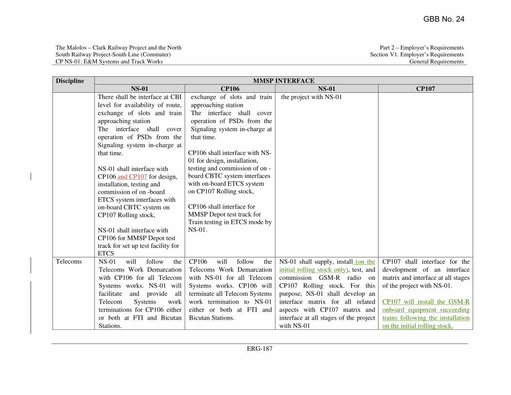
The Malolos – Clark Railway Project and the North
South Railway Project-South Line (Commuter)
CP NS-01: E&M Systems and Track Works
Part 2 – Employer’s Requirements
Section V1. Employer’s Requirements
General Requirements
ERG-187
Discipline MMSP INTERFACE
NS-01 CP106 NS-01 CP107
There shall be interface at CBI
level for availability of route,
exchange of slots and train
approaching station
The interface shall cover
operation of PSDs from the
Signaling system in-charge at
that time.
NS-01 shall interface with
CP106 and CP107 for design,
installation, testing and
commission of on -board
ETCS system interfaces with
on-board CBTC system on
CP107 Rolling stock,
NS-01 shall interface with
CP106 for MMSP Depot test
track for set up test facility for
ETCS
exchange of slots and train
approaching station
The interface shall cover
operation of PSDs from the
Signaling system in-charge at
that time.
CP106 shall interface with NS-
01 for design, installation,
testing and commission of on -
board CBTC system interfaces
with on-board ETCS system
on CP107 Rolling stock,
CP106 shall interface for
MMSP Depot test track for
Train testing in ETCS mode by
NS-01.
the project with NS-01
Telecoms NS-01 will follow the
Telecoms Work Demarcation
with CP106 for all Telecom
Systems works. NS-01 will
facilitate and provide all
Telecom Systems work
terminations for CP106 either
or both at FTI and Bicutan
Stations.
CP106 will follow the
Telecoms Work Demarcation
with NS-01 for all Telecom
Systems works. CP106 will
terminate all Telecom Systems
work termination to NS-01
either or both at FTI and
Bicutan Stations.
NS-01 shall supply, install (on the
initial rolling stock only), test, and
commission GSM-R radio on
CP107 Rolling stock. For this
purpose, NS-01 shall develop an
interface matrix for all related
aspects with CP107 matrix and
interface at all stages of the project
with NS-01
CP107 shall interface for the
development of an interface
matrix and interface at all stages
of the project with NS-01.
CP107 will install the GSM-R
onboard equipment succeeding
trains following the installation
on the initial rolling stock.
GBB No. 24
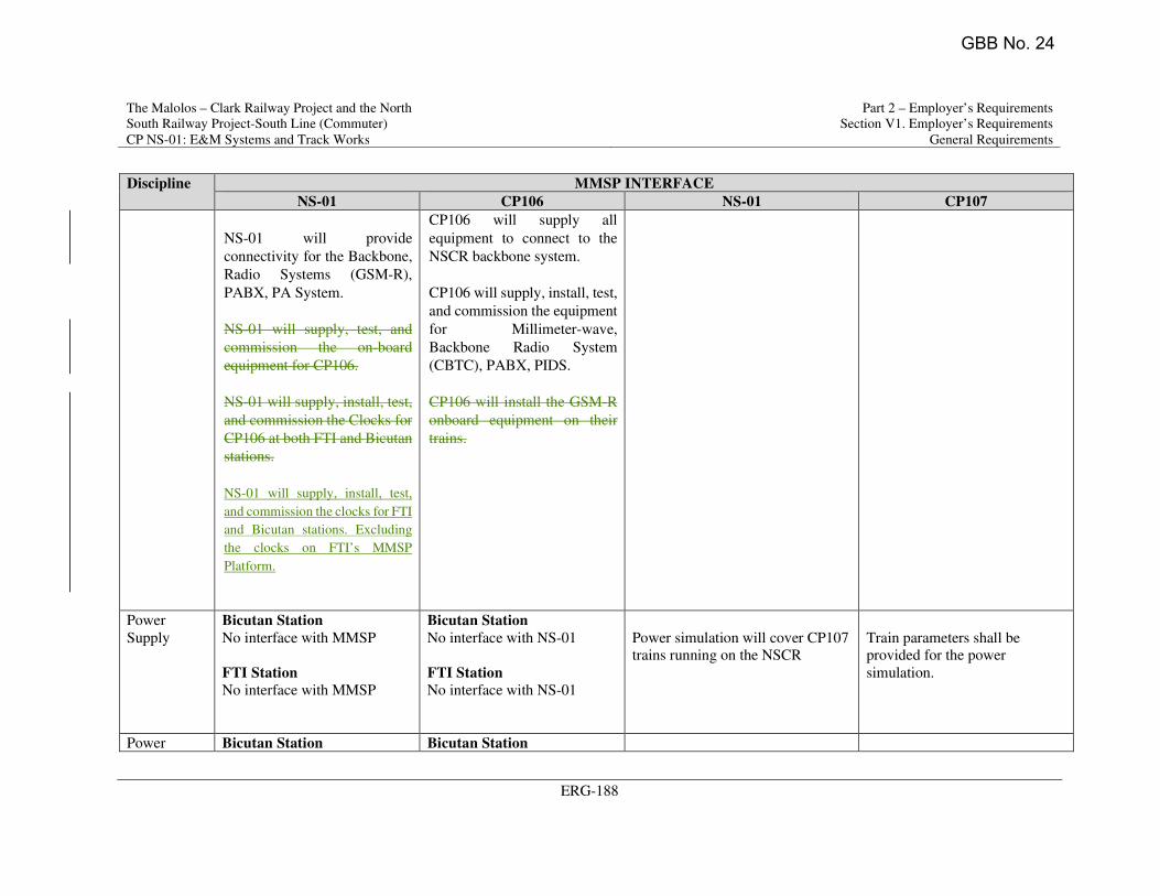
The Malolos – Clark Railway Project and the North
South Railway Project-South Line (Commuter)
CP NS-01: E&M Systems and Track Works
Part 2 – Employer’s Requirements
Section V1. Employer’s Requirements
General Requirements
ERG-188
Discipline MMSP INTERFACE
NS-01 CP106 NS-01 CP107
NS-01 will provide
connectivity for the Backbone,
Radio Systems (GSM-R),
PABX, PA System.
NS-01 will supply, test, and
commission the on-board
equipment for CP106.
NS-01 will supply, install, test,
and commission the Clocks for
CP106 at both FTI and Bicutan
stations.
NS-01 will supply, install, test,
and commission the clocks for FTI
and Bicutan stations. Excluding
the clocks on FTI’s MMSP
Platform.
CP106 will supply all
equipment to connect to the
NSCR backbone system.
CP106 will supply, install, test,
and commission the equipment
for Millimeter-wave,
Backbone Radio System
(CBTC), PABX, PIDS.
CP106 will install the GSM-R
onboard equipment on their
trains.
Power
Supply
Bicutan Station
No interface with MMSP
FTI Station
No interface with MMSP
Bicutan Station
No interface with NS-01
FTI Station
No interface with NS-01
Power simulation will cover CP107
trains running on the NSCR
Train parameters shall be
provided for the power
simulation.
Power Bicutan Station Bicutan Station
GBB No. 24
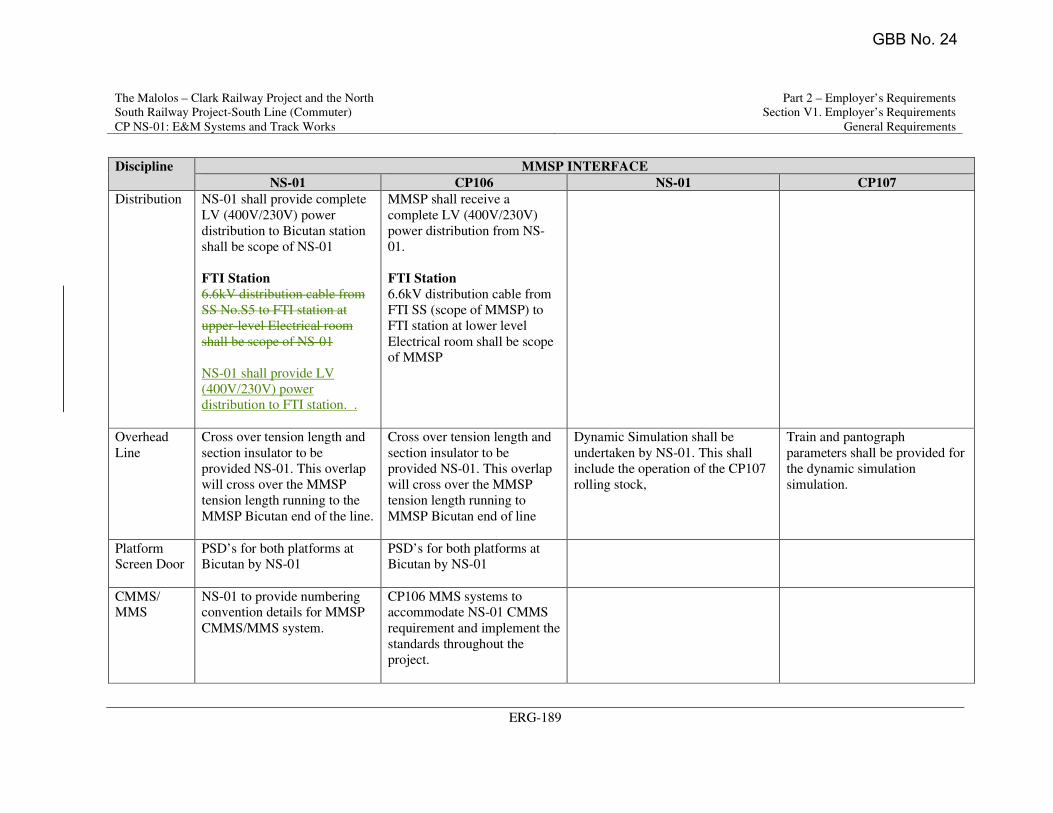
The Malolos – Clark Railway Project and the North
South Railway Project-South Line (Commuter)
CP NS-01: E&M Systems and Track Works
Part 2 – Employer’s Requirements
Section V1. Employer’s Requirements
General Requirements
ERG-189
Discipline MMSP INTERFACE
NS-01 CP106 NS-01 CP107
Distribution NS-01 shall provide complete
LV (400V/230V) power
distribution to Bicutan station
shall be scope of NS-01
FTI Station
6.6kV distribution cable from
SS No.S5 to FTI station at
upper-level Electrical room
shall be scope of NS-01
NS-01 shall provide LV
(400V/230V) power
distribution to FTI station. .
MMSP shall receive a
complete LV (400V/230V)
power distribution from NS-
01.
FTI Station
6.6kV distribution cable from
FTI SS (scope of MMSP) to
FTI station at lower level
Electrical room shall be scope
of MMSP
Overhead
Line
Cross over tension length and
section insulator to be
provided NS-01. This overlap
will cross over the MMSP
tension length running to the
MMSP Bicutan end of the line.
Cross over tension length and
section insulator to be
provided NS-01. This overlap
will cross over the MMSP
tension length running to
MMSP Bicutan end of line
Dynamic Simulation shall be
undertaken by NS-01. This shall
include the operation of the CP107
rolling stock,
Train and pantograph
parameters shall be provided for
the dynamic simulation
simulation.
Platform
Screen Door
PSD’s for both platforms at
Bicutan by NS-01
PSD’s for both platforms at
Bicutan by NS-01
CMMS/
MMS
NS-01 to provide numbering
convention details for MMSP
CMMS/MMS system.
CP106 MMS systems to
accommodate NS-01 CMMS
requirement and implement the
standards throughout the
project.
GBB No. 24
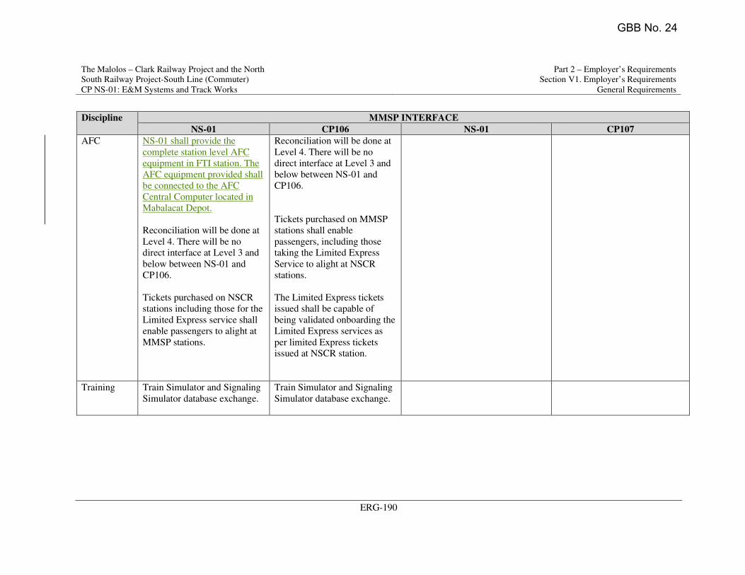
The Malolos – Clark Railway Project and the North
South Railway Project-South Line (Commuter)
CP NS-01: E&M Systems and Track Works
Part 2 – Employer’s Requirements
Section V1. Employer’s Requirements
General Requirements
ERG-190
Discipline MMSP INTERFACE
NS-01 CP106 NS-01 CP107
AFC NS-01 shall provide the
complete station level AFC
equipment in FTI station. The
AFC equipment provided shall
be connected to the AFC
Central Computer located in
Mabalacat Depot.
Reconciliation will be done at
Level 4. There will be no
direct interface at Level 3 and
below between NS-01 and
CP106.
Tickets purchased on NSCR
stations including those for the
Limited Express service shall
enable passengers to alight at
MMSP stations.
Reconciliation will be done at
Level 4. There will be no
direct interface at Level 3 and
below between NS-01 and
CP106.
Tickets purchased on MMSP
stations shall enable
passengers, including those
taking the Limited Express
Service to alight at NSCR
stations.
The Limited Express tickets
issued shall be capable of
being validated onboarding the
Limited Express services as
per limited Express tickets
issued at NSCR station.
Training Train Simulator and Signaling
Simulator database exchange.
Train Simulator and Signaling
Simulator database exchange.
GBB No. 24
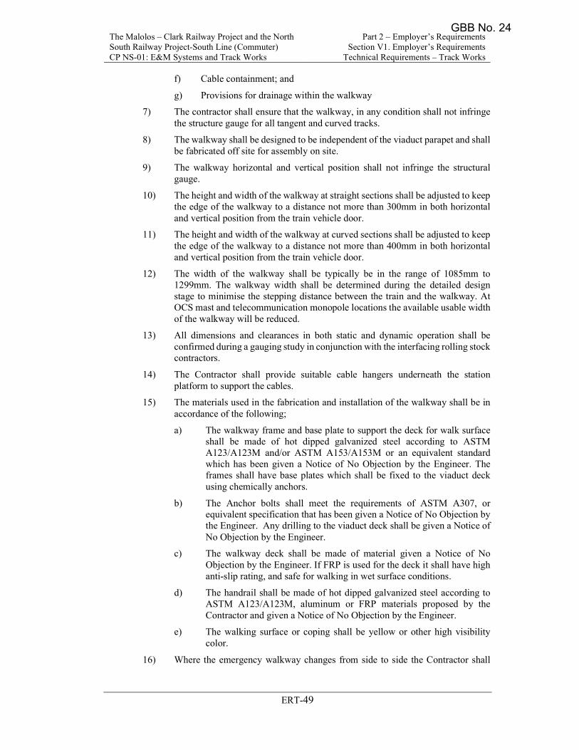
The Malolos – Clark Railway Project and the North South Railway Project-South Line (Commuter) CP NS-01: E&M Systems and Track Works
Part 2 – Employer’s Requirements Section V1. Employer’s Requirements
Technical Requirements – Track Works
ERT-49
f) Cable containment; and
g) Provisions for drainage within the walkway
7) The contractor shall ensure that the walkway, in any condition shall not infringe the structure gauge for all tangent and curved tracks.
8) The walkway shall be designed to be independent of the viaduct parapet and shall be fabricated off site for assembly on site.
9) The walkway horizontal and vertical position shall not infringe the structural gauge.
10) The height and width of the walkway at straight sections shall be adjusted to keep the edge of the walkway to a distance not more than 300mm in both horizontal and vertical position from the train vehicle door.
11) The height and width of the walkway at curved sections shall be adjusted to keep the edge of the walkway to a distance not more than 400mm in both horizontal and vertical position from the train vehicle door.
12) The width of the walkway shall be typically be in the range of 1085mm to 1299mm. The walkway width shall be determined during the detailed design stage to minimise the stepping distance between the train and the walkway. At OCS mast and telecommunication monopole locations the available usable width of the walkway will be reduced.
13) All dimensions and clearances in both static and dynamic operation shall be confirmed during a gauging study in conjunction with the interfacing rolling stock contractors.
14) The Contractor shall provide suitable cable hangers underneath the station platform to support the cables.
15) The materials used in the fabrication and installation of the walkway shall be in accordance of the following;
a) The walkway frame and base plate to support the deck for walk surface shall be made of hot dipped galvanized steel according to ASTM A123/A123M and/or ASTM A153/A153M or an equivalent standard which has been given a Notice of No Objection by the Engineer. The frames shall have base plates which shall be fixed to the viaduct deck using chemically anchors.
b) The Anchor bolts shall meet the requirements of ASTM A307, or equivalent specification that has been given a Notice of No Objection by the Engineer. Any drilling to the viaduct deck shall be given a Notice of No Objection by the Engineer.
c) The walkway deck shall be made of material given a Notice of No Objection by the Engineer. If FRP is used for the deck it shall have high anti-slip rating, and safe for walking in wet surface conditions.
d) The handrail shall be made of hot dipped galvanized steel according to ASTM A123/A123M, aluminum or FRP materials proposed by the Contractor and given a Notice of No Objection by the Engineer.
e) The walking surface or coping shall be yellow or other high visibility color.
16) Where the emergency walkway changes from side to side the Contractor shall
GBB No. 24
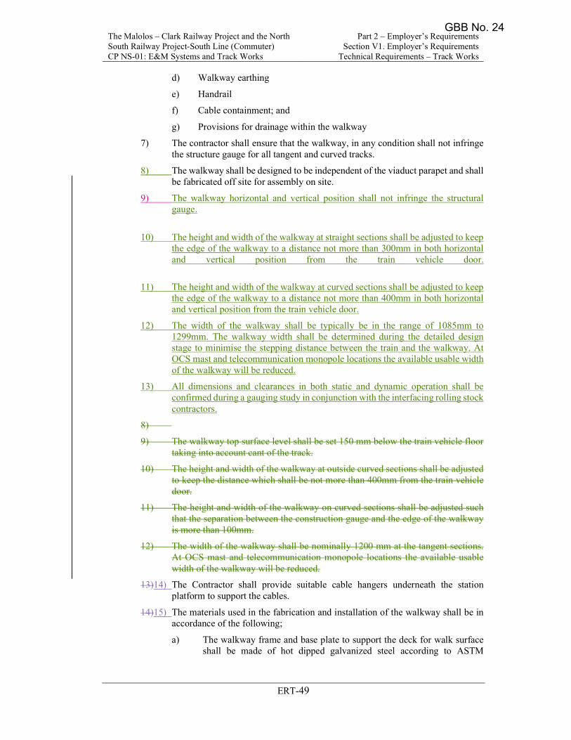
The Malolos – Clark Railway Project and the North South Railway Project-South Line (Commuter) CP NS-01: E&M Systems and Track Works
Part 2 – Employer’s Requirements Section V1. Employer’s Requirements
Technical Requirements – Track Works
ERT-49
d) Walkway earthing
e) Handrail
f) Cable containment; and
g) Provisions for drainage within the walkway
7) The contractor shall ensure that the walkway, in any condition shall not infringe the structure gauge for all tangent and curved tracks.
8) The walkway shall be designed to be independent of the viaduct parapet and shall be fabricated off site for assembly on site.
9) The walkway horizontal and vertical position shall not infringe the structural gauge.
10) The height and width of the walkway at straight sections shall be adjusted to keep the edge of the walkway to a distance not more than 300mm in both horizontal and vertical position from the train vehicle door.
11) The height and width of the walkway at curved sections shall be adjusted to keep the edge of the walkway to a distance not more than 400mm in both horizontal and vertical position from the train vehicle door.
12) The width of the walkway shall be typically be in the range of 1085mm to 1299mm. The walkway width shall be determined during the detailed design stage to minimise the stepping distance between the train and the walkway. At OCS mast and telecommunication monopole locations the available usable width of the walkway will be reduced.
13) All dimensions and clearances in both static and dynamic operation shall be confirmed during a gauging study in conjunction with the interfacing rolling stock contractors.
8)
9) The walkway top surface level shall be set 150 mm below the train vehicle floor taking into account cant of the track.
10) The height and width of the walkway at outside curved sections shall be adjusted to keep the distance which shall be not more than 400mm from the train vehicle door.
11) The height and width of the walkway on curved sections shall be adjusted such that the separation between the construction gauge and the edge of the walkway is more than 100mm.
12) The width of the walkway shall be nominally 1200 mm at the tangent sections. At OCS mast and telecommunication monopole locations the available usable width of the walkway will be reduced.
13)14) The Contractor shall provide suitable cable hangers underneath the station platform to support the cables.
14)15) The materials used in the fabrication and installation of the walkway shall be in accordance of the following;
a) The walkway frame and base plate to support the deck for walk surface shall be made of hot dipped galvanized steel according to ASTM
GBB No. 24
The Malolos – Clark Railway Project and the North South Railway Project-South Line (Commuter) CP NS-01: E&M Systems and Track Works
Part 2 – Employer’s Requirements Section V1. Employer’s Requirements
Technical Requirements - OCS
ERT - 562
2) Positive power feeder and negative return cable connections at traction substation.
3) Lightning/Surge Arrester, devices.
As certain works are closely related to civil, architecture, track works, signaling system, Communications System, power delivery system, traction substation, rolling stock, water drain system, water delivery system for firefighting, depot inspection, and operation system, the Contractor shall coordinate with interfacing Contractors for installation works including but not limited to:
a) Supporting structure for feeders and return cables in elevated, embankment section and depot;
b) Installation of return cables fixed with a high resistivity fire-proofed cleat.
c) Crossing conduit for return cables passed through under the plinth, or between plinth gaps or sleeper gaps;
d) Steel tubular pole foundation and guy anchor in elevated and embankment section;
e) Earthing connection between a pole earthing wire and earthing wire on elevated sand embankment sections. The Contractor shall install earthing electrode with resistance prescribed by the provisions and regulations;
f) Connection between lead wire from surge arrester and grounding wire inside PVC conduit embedded along every concrete pier, or at every other concrete pier (depends upon the design of the Contractor to be Approved by the Engineer);
g) Cable wiring for earthing devices of grounding wire and surge arrester for lightning;
h) Excavation, backfill, compacting, and finishes of trough, hand-holes, and pipe conduit for feeders, overhead return wire and return cable in depot; and
i) Furthermore, any matter not stipulated herein shall be determined through mutual consultation between the Engineer and Contractor, with the Engineer’s consent ultimately.
4) Sectioning and feeding in the depots shall be designed to suit the various stages of construction and operation up to completion. The sectioning shall be designed to minimize disruption to operation during isolations for maintenance work.
5) For each of the 3 no. high level walkways in the Mabalacat Depot workshop, interlocking shall be provided between the isolators and the doors giving access to the platforms. The scope of works includes doors, door locks, push bar for emergency escape and associated interlocking for isolators. The contractor shall coordinate with the civil contractor regarding the implementation of this systems with the access door.
6.2.4 Environmental Conditions
1) Ambient conditions and usage environments
Table 6.2.2 Ambient Conditions and Usage Environments
GBB No. 24
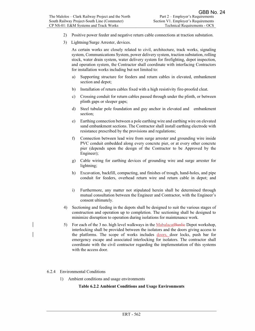
The Malolos – Clark Railway Project and the North South Railway Project-South Line (Commuter) CP NS-01: E&M Systems and Track Works
Part 2 – Employer’s Requirements Section V1. Employer’s Requirements
Technical Requirements - OCS
ERT - 562
2) Positive power feeder and negative return cable connections at traction substation.
3) Lightning/Surge Arrester, devices.
As certain works are closely related to civil, architecture, track works, signaling system, Communications System, power delivery system, traction substation, rolling stock, water drain system, water delivery system for firefighting, depot inspection, and operation system, the Contractor shall coordinate with interfacing Contractors for installation works including but not limited to:
a) Supporting structure for feeders and return cables in elevated, embankment section and depot;
b) Installation of return cables fixed with a high resistivity fire-proofed cleat.
c) Crossing conduit for return cables passed through under the plinth, or between plinth gaps or sleeper gaps;
d) Steel tubular pole foundation and guy anchor in elevated and embankment section;
e) Earthing connection between a pole earthing wire and earthing wire on elevated sand embankment sections. The Contractor shall install earthing electrode with resistance prescribed by the provisions and regulations;
f) Connection between lead wire from surge arrester and grounding wire inside PVC conduit embedded along every concrete pier, or at every other concrete pier (depends upon the design of the Contractor to be Approved by the Engineer);
g) Cable wiring for earthing devices of grounding wire and surge arrester for lightning;
h) Excavation, backfill, compacting, and finishes of trough, hand-holes, and pipe conduit for feeders, overhead return wire and return cable in depot; and
i) Furthermore, any matter not stipulated herein shall be determined through mutual consultation between the Engineer and Contractor, with the Engineer’s consent ultimately.
4) Sectioning and feeding in the depots shall be designed to suit the various stages of construction and operation up to completion. The sectioning shall be designed to minimize disruption to operation during isolations for maintenance work.
5) For each of the 3 no. high level walkways in the MabalacatBanlic Depot workshop, interlocking shall be provided between the isolators and the doors giving access to the platforms. The scope of works includes doors, door locks, push bar for emergency escape and associated interlocking for isolators. The contractor shall coordinate with the civil contractor regarding the implementation of this systems with the access door.
6.2.4 Environmental Conditions
1) Ambient conditions and usage environments
Table 6.2.2 Ambient Conditions and Usage Environments
GBB No. 24
The Malolos – Clark Railway Project and the North South Railway Project-South Line (Commuter) CP NS-01: E&M Systems and Track Works
Part 2 – Employer’s Requirements Section V1. Employer’s Requirements
Technical Requirements - Telecommunications
ERT-266
distribution over designated the designated frequency band for the NSCR application;
i) Antenna and support structure for base stations throughout the system and at the Depots etc.
j) Lightning protection equipment;
k) Distribution frames;
l) Equipment cabinets, racks, and cubicles together with mounting brackets and installation material;
m) Power supplies, cable, connectors, accessories, cabling, and earthing necessary for all equipment for the works;
n) All software required for operation and maintenance of the radio system;
o) Radio network management system;
p) A3/A4 Laser Color printer, connected to the radio management system;
q) Special maintenance tools, measurement tools, and laptops for onsite diagnosis and maintenance; and
r) SIM-card for onboard data radio. The onboard data radios, required for the signaling system, are excluded from the supply of the radio system. Those radios will be included in the scope of the signaling system.
s) Cradle with charger for driver handheld GSM-R unit, to be installed in each cabin of the train.
2.3 Scope of Services
The Contractor shall liaise with all concerned authorities such as the National Telecommunications Commission (NTC) for obtaining the equipment approvals, and to any other authorities to obtain any necessary licenses, clearances, or permits for the supply, installation and commissioning of the Radio System.
The Radio Frequency Operating License shall be applied and obtained by the Employer with the NTC, as the Employer will be the Owner of the Frequency Band.
The Contractor shall coordinate with PTE operators and equipment owners in case of interference problems through a Spectrum Coordination Committee.
Further to the general requirements shall include:
1) The Contractor shall coordinate with Civil Works Project Contractors to provide comments or recommendation on the station and Depot buildings, finishes, architectural layouts, installation requirements for antenna supports, availability of duct support facilities for antennas, masts, and other cables;
2) The Contractor shall also coordinate and supervise the installation of the Train-borne Radio equipment with the Rolling Stock manufacturers, to guarantee the interfaces and the end to end solution;
3) The Contractor shall coordinate with the contractors of the adjacent projects and implement all required interfacing equipment to ensure a seamless hand-over without losing any active radio connection;
4) Furthermore, the Contractor will be required to coordinate and interface to any sub-system Contractors;
5) The Contractor shall produce all detailed design documents and drawings. Full
GBB No. 24
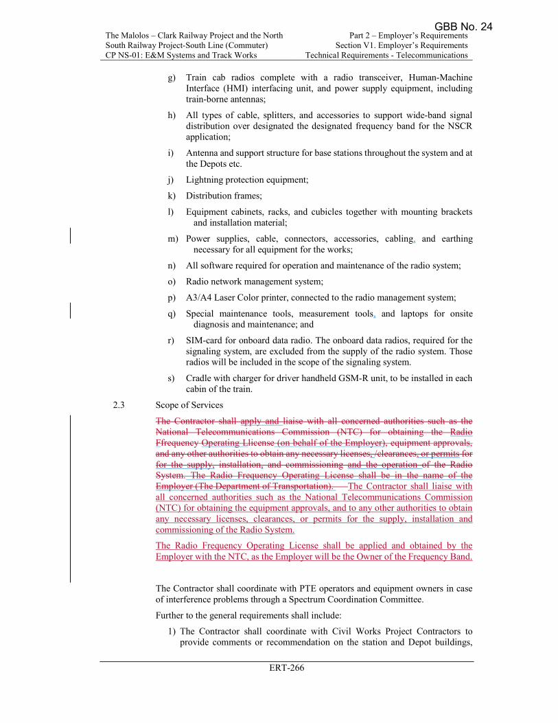
The Malolos – Clark Railway Project and the North South Railway Project-South Line (Commuter) CP NS-01: E&M Systems and Track Works
Part 2 – Employer’s Requirements Section V1. Employer’s Requirements
Technical Requirements - Telecommunications
ERT-266
g) Train cab radios complete with a radio transceiver, Human-Machine Interface (HMI) interfacing unit, and power supply equipment, including train-borne antennas;
h) All types of cable, splitters, and accessories to support wide-band signal distribution over designated the designated frequency band for the NSCR application;
i) Antenna and support structure for base stations throughout the system and at the Depots etc.
j) Lightning protection equipment;
k) Distribution frames;
l) Equipment cabinets, racks, and cubicles together with mounting brackets and installation material;
m) Power supplies, cable, connectors, accessories, cabling, and earthing necessary for all equipment for the works;
n) All software required for operation and maintenance of the radio system;
o) Radio network management system;
p) A3/A4 Laser Color printer, connected to the radio management system;
q) Special maintenance tools, measurement tools, and laptops for onsite diagnosis and maintenance; and
r) SIM-card for onboard data radio. The onboard data radios, required for the signaling system, are excluded from the supply of the radio system. Those radios will be included in the scope of the signaling system.
s) Cradle with charger for driver handheld GSM-R unit, to be installed in each cabin of the train.
2.3 Scope of Services
The Contractor shall apply and liaise with all concerned authorities such as the National Telecommunications Commission (NTC) for obtaining the Radio Ffrequency Operating Llicense (on behalf of the Employer), equipment approvals, and any other authorities to obtain any necessary licenses, /clearances, or permits for for the supply, installation, and commissioning and the operation of the Radio System. The Radio Frequency Operating License shall be in the name of the Employer (The Department of Transportation). The Contractor shall liaise with all concerned authorities such as the National Telecommunications Commission (NTC) for obtaining the equipment approvals, and to any other authorities to obtain any necessary licenses, clearances, or permits for the supply, installation and commissioning of the Radio System.
The Radio Frequency Operating License shall be applied and obtained by the Employer with the NTC, as the Employer will be the Owner of the Frequency Band.
The Contractor shall coordinate with PTE operators and equipment owners in case of interference problems through a Spectrum Coordination Committee.
Further to the general requirements shall include:
1) The Contractor shall coordinate with Civil Works Project Contractors to provide comments or recommendation on the station and Depot buildings,
GBB No. 24
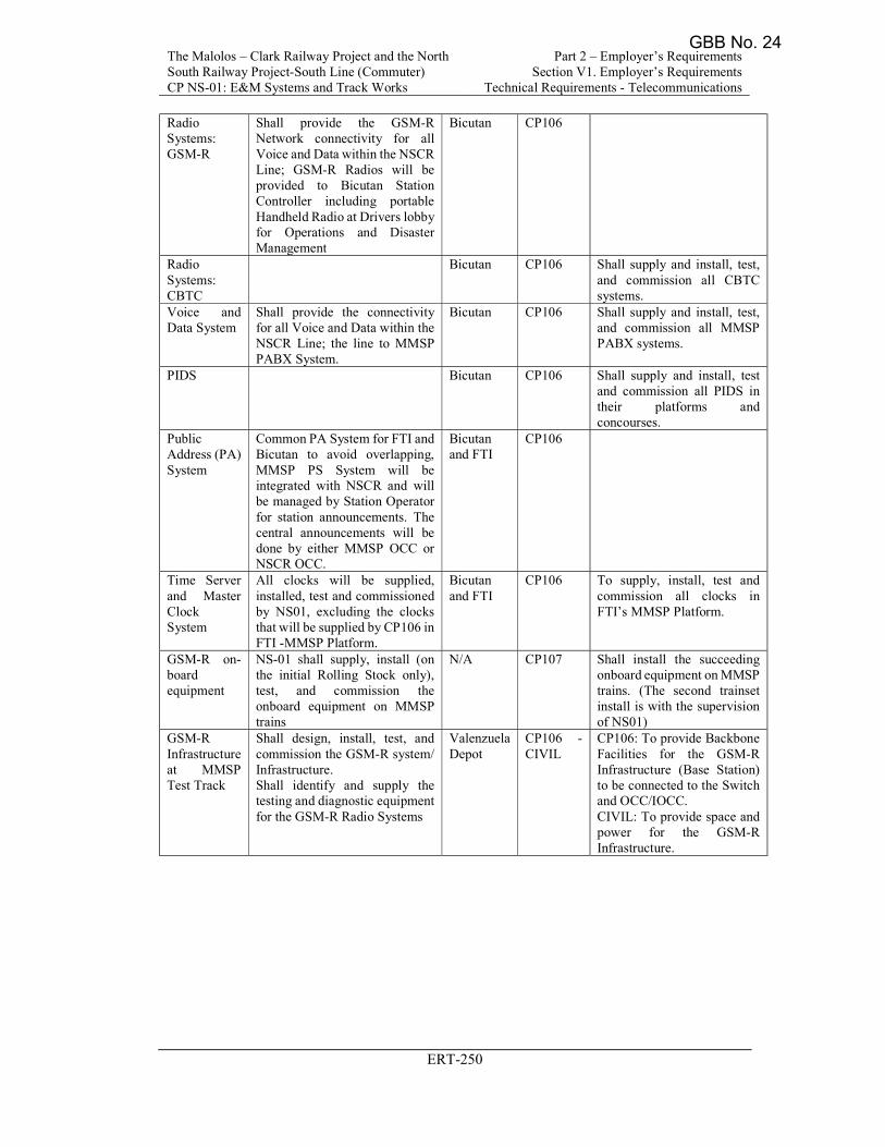
The Malolos – Clark Railway Project and the North South Railway Project-South Line (Commuter) CP NS-01: E&M Systems and Track Works
Part 2 – Employer’s Requirements Section V1. Employer’s Requirements
Technical Requirements - Telecommunications
ERT-250
Radio Systems: GSM-R
Shall provide the GSM-R Network connectivity for all Voice and Data within the NSCR Line; GSM-R Radios will be provided to Bicutan Station Controller including portable Handheld Radio at Drivers lobby for Operations and Disaster Management
Bicutan CP106
Radio Systems: CBTC
Bicutan CP106 Shall supply and install, test, and commission all CBTC systems.
Voice and Data System
Shall provide the connectivity for all Voice and Data within the NSCR Line; the line to MMSP PABX System.
Bicutan CP106 Shall supply and install, test, and commission all MMSP PABX systems.
PIDS Bicutan CP106 Shall supply and install, test and commission all PIDS in their platforms and concourses.
Public Address (PA) System
Common PA System for FTI and Bicutan to avoid overlapping, MMSP PS System will be integrated with NSCR and will be managed by Station Operator for station announcements. The central announcements will be done by either MMSP OCC or NSCR OCC.
Bicutan and FTI
CP106
Time Server and Master Clock System
All clocks will be supplied, installed, test and commissioned by NS01, excluding the clocks that will be supplied by CP106 in FTI -MMSP Platform.
Bicutan and FTI
CP106 To supply, install, test and commission all clocks in FTI’s MMSP Platform.
GSM-R on-board equipment
NS-01 shall supply, install (on the initial Rolling Stock only), test, and commission the onboard equipment on MMSP trains
N/A CP107 Shall install the succeeding onboard equipment on MMSP trains. (The second trainset install is with the supervision of NS01)
GSM-R Infrastructure at MMSP Test Track
Shall design, install, test, and commission the GSM-R system/ Infrastructure. Shall identify and supply the testing and diagnostic equipment for the GSM-R Radio Systems
Valenzuela Depot
CP106 - CIVIL
CP106: To provide Backbone Facilities for the GSM-R Infrastructure (Base Station) to be connected to the Switch and OCC/IOCC. CIVIL: To provide space and power for the GSM-R Infrastructure.
GBB No. 24
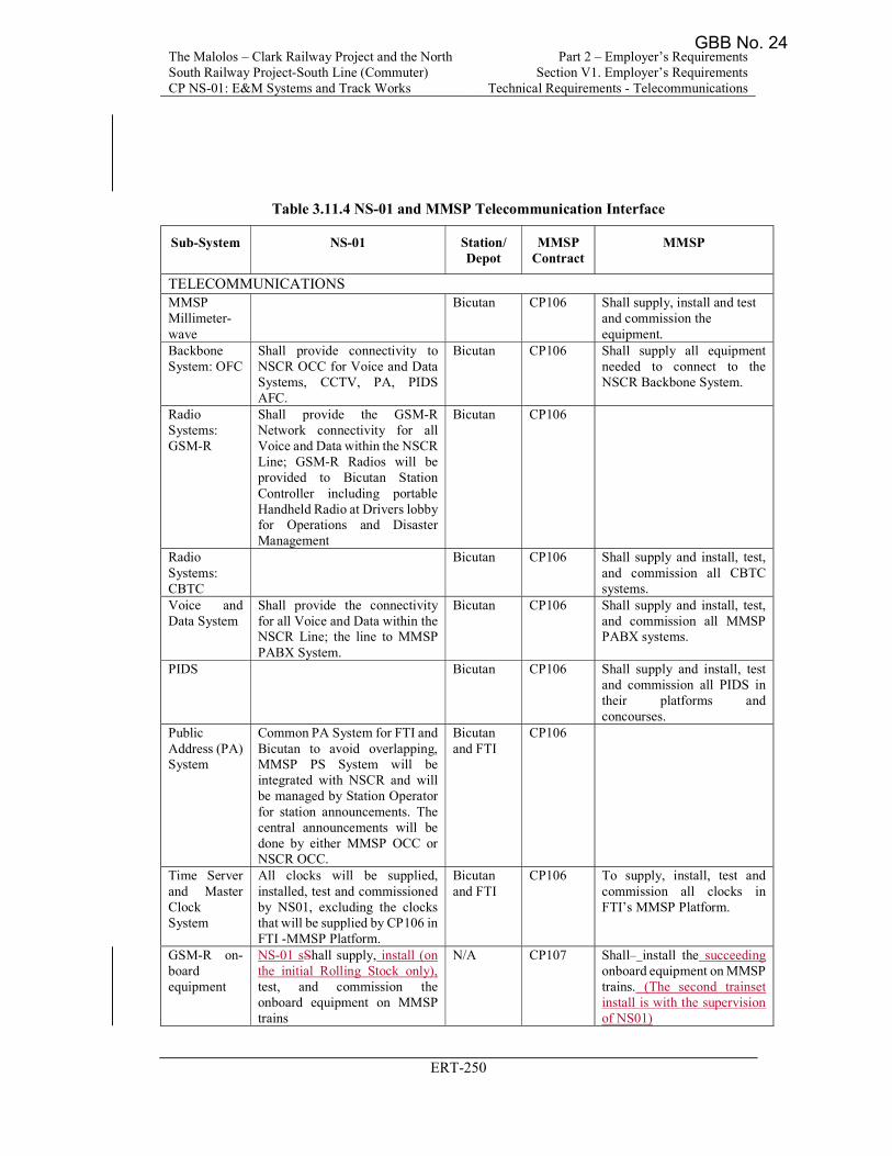
The Malolos – Clark Railway Project and the North South Railway Project-South Line (Commuter) CP NS-01: E&M Systems and Track Works
Part 2 – Employer’s Requirements Section V1. Employer’s Requirements
Technical Requirements - Telecommunications
ERT-250
Table 3.11.4 NS-01 and MMSP Telecommunication Interface
Sub-System NS-01 Station/ Depot
MMSP Contract
MMSP
TELECOMMUNICATIONS MMSP Millimeter-wave
Bicutan CP106 Shall supply, install and test and commission the equipment.
Backbone System: OFC
Shall provide connectivity to NSCR OCC for Voice and Data Systems, CCTV, PA, PIDS AFC.
Bicutan CP106 Shall supply all equipment needed to connect to the NSCR Backbone System.
Radio Systems: GSM-R
Shall provide the GSM-R Network connectivity for all Voice and Data within the NSCR Line; GSM-R Radios will be provided to Bicutan Station Controller including portable Handheld Radio at Drivers lobby for Operations and Disaster Management
Bicutan CP106
Radio Systems: CBTC
Bicutan CP106 Shall supply and install, test, and commission all CBTC systems.
Voice and Data System
Shall provide the connectivity for all Voice and Data within the NSCR Line; the line to MMSP PABX System.
Bicutan CP106 Shall supply and install, test, and commission all MMSP PABX systems.
PIDS Bicutan CP106 Shall supply and install, test and commission all PIDS in their platforms and concourses.
Public Address (PA) System
Common PA System for FTI and Bicutan to avoid overlapping, MMSP PS System will be integrated with NSCR and will be managed by Station Operator for station announcements. The central announcements will be done by either MMSP OCC or NSCR OCC.
Bicutan and FTI
CP106
Time Server and Master Clock System
All clocks will be supplied, installed, test and commissioned by NS01, excluding the clocks that will be supplied by CP106 in FTI -MMSP Platform.
Bicutan and FTI
CP106 To supply, install, test and commission all clocks in FTI’s MMSP Platform.
GSM-R on-board equipment
NS-01 sShall supply, install (on the initial Rolling Stock only), test, and commission the onboard equipment on MMSP trains
N/A CP107 Shall install the succeeding onboard equipment on MMSP trains. (The second trainset install is with the supervision of NS01)
GBB No. 24
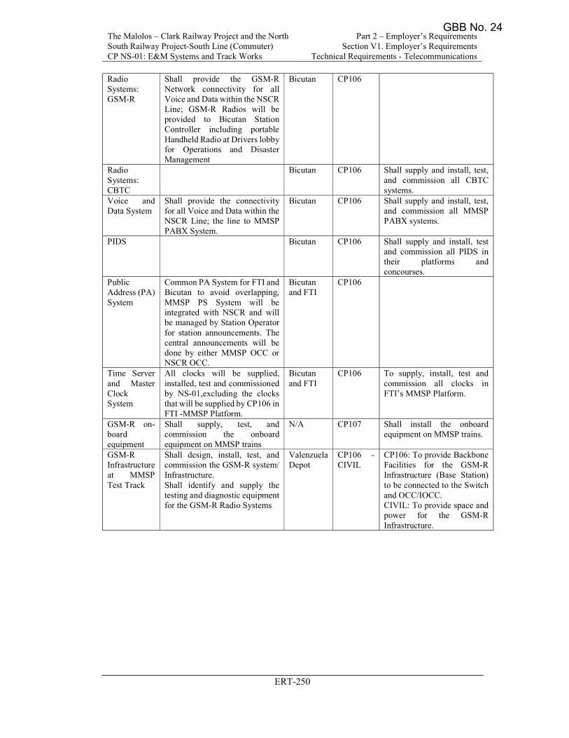
The Malolos – Clark Railway Project and the North South Railway Project-South Line (Commuter) CP NS-01: E&M Systems and Track Works
Part 2 – Employer’s Requirements Section V1. Employer’s Requirements
Technical Requirements - Telecommunications
ERT-250
Radio Systems: GSM-R
Shall provide the GSM-R Network connectivity for all Voice and Data within the NSCR Line; GSM-R Radios will be provided to Bicutan Station Controller including portable Handheld Radio at Drivers lobby for Operations and Disaster Management
Bicutan CP106
Radio Systems: CBTC
Bicutan CP106 Shall supply and install, test, and commission all CBTC systems.
Voice and Data System
Shall provide the connectivity for all Voice and Data within the NSCR Line; the line to MMSP PABX System.
Bicutan CP106 Shall supply and install, test, and commission all MMSP PABX systems.
PIDS Bicutan CP106 Shall supply and install, test and commission all PIDS in their platforms and concourses.
Public Address (PA) System
Common PA System for FTI and Bicutan to avoid overlapping, MMSP PS System will be integrated with NSCR and will be managed by Station Operator for station announcements. The central announcements will be done by either MMSP OCC or NSCR OCC.
Bicutan and FTI
CP106
Time Server and Master Clock System
All clocks will be supplied, installed, test and commissioned by NS-01,excluding the clocks that will be supplied by CP106 in FTI -MMSP Platform.
Bicutan and FTI
CP106 To supply, install, test and commission all clocks in FTI’s MMSP Platform.
GSM-R on-board equipment
Shall supply, test, and commission the onboard equipment on MMSP trains
N/A CP107 Shall install the onboard equipment on MMSP trains.
GSM-R Infrastructure at MMSP Test Track
Shall design, install, test, and commission the GSM-R system/ Infrastructure. Shall identify and supply the testing and diagnostic equipment for the GSM-R Radio Systems
Valenzuela Depot
CP106 - CIVIL
CP106: To provide Backbone Facilities for the GSM-R Infrastructure (Base Station) to be connected to the Switch and OCC/IOCC. CIVIL: To provide space and power for the GSM-R Infrastructure.
GBB No. 24
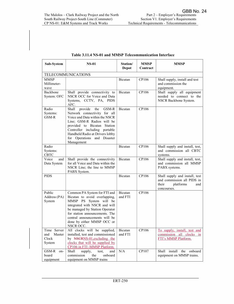
The Malolos – Clark Railway Project and the North South Railway Project-South Line (Commuter) CP NS-01: E&M Systems and Track Works
Part 2 – Employer’s Requirements Section V1. Employer’s Requirements
Technical Requirements - Telecommunications
ERT-250
Table 3.11.4 NS-01 and MMSP Telecommunication Interface
Sub-System NS-01 Station/ Depot
MMSP Contract
MMSP
TELECOMMUNICATIONS MMSP Millimeter-wave
Bicutan CP106 Shall supply, install and test and commission the equipment.
Backbone System: OFC
Shall provide connectivity to NSCR OCC for Voice and Data Systems, CCTV, PA, PIDS AFC.
Bicutan CP106 Shall supply all equipment needed to connect to the NSCR Backbone System.
Radio Systems: GSM-R
Shall provide the GSM-R Network connectivity for all Voice and Data within the NSCR Line; GSM-R Radios will be provided to Bicutan Station Controller including portable Handheld Radio at Drivers lobby for Operations and Disaster Management
Bicutan CP106
Radio Systems: CBTC
Bicutan CP106 Shall supply and install, test, and commission all CBTC systems.
Voice and Data System
Shall provide the connectivity for all Voice and Data within the NSCR Line; the line to MMSP PABX System.
Bicutan CP106 Shall supply and install, test, and commission all MMSP PABX systems.
PIDS Bicutan CP106 Shall supply and install, test and commission all PIDS in their platforms and concourses.
Public Address (PA) System
Common PA System for FTI and Bicutan to avoid overlapping, MMSP PS System will be integrated with NSCR and will be managed by Station Operator for station announcements. The central announcements will be done by either MMSP OCC or NSCR OCC.
Bicutan and FTI
CP106
Time Server and Master Clock System
All clocks will be supplied, installed, test and commissioned by NSCRNS-01,excluding the clocks that will be supplied by CP106 in FTI -MMSP Platform.
Bicutan and FTI
CP106 To supply, install, test and commission all clocks in FTI’s MMSP Platform.
GSM-R on-board equipment
Shall supply, test, and commission the onboard equipment on MMSP trains
N/A CP107 Shall install the onboard equipment on MMSP trains.
GBB No. 24
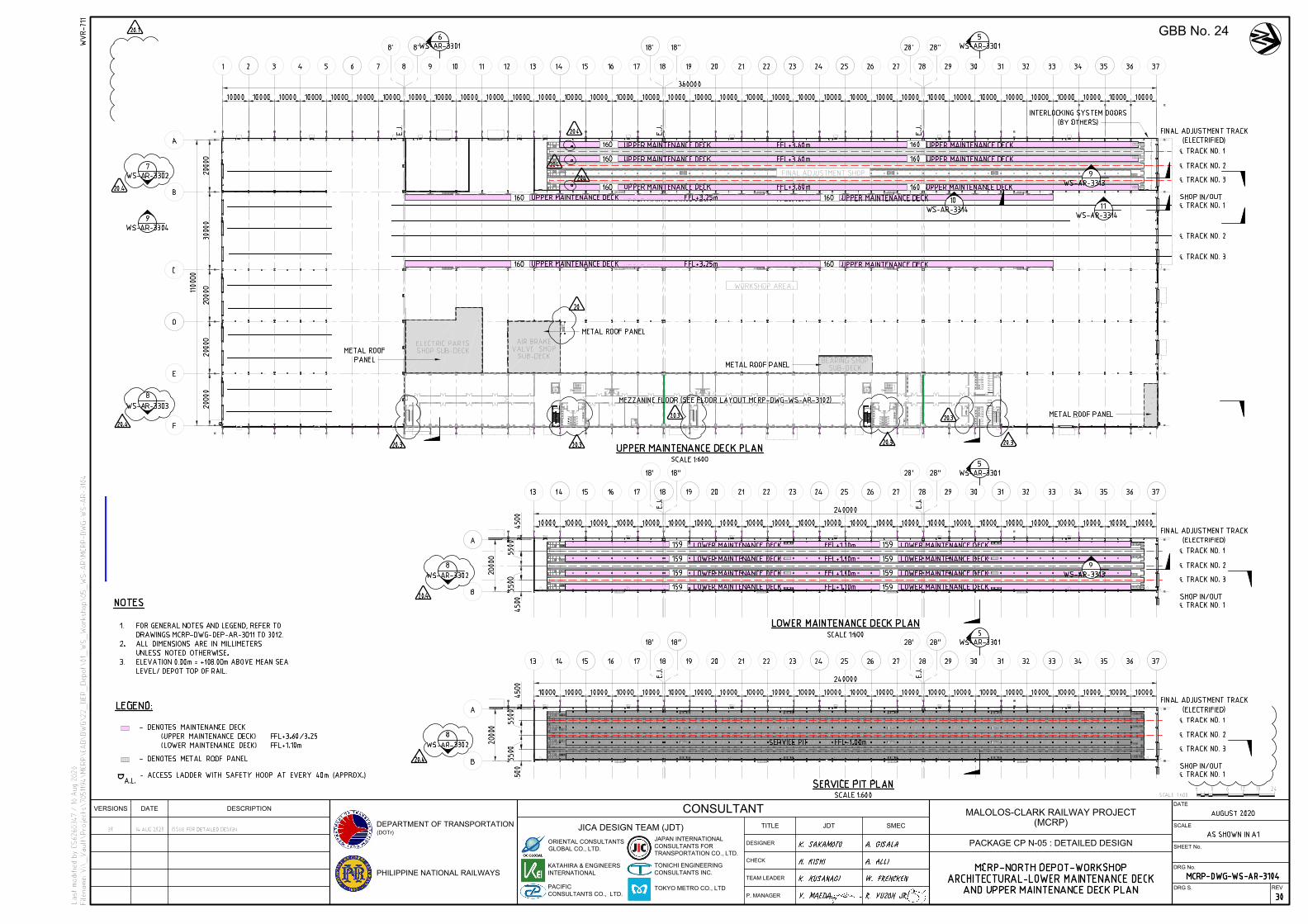
℄
℄
℄
℄
℄
℄
℄
℄
℄
℄
℄
℄
℄
℄
PHILIPPINE NATIONAL RAILWAYS
TEAM LEADER
P. MANAGER
SMEC
VERSIONS DATE DESCRIPTION
CONSULTANT
TITLE
CHECK
DESIGNER
JICA DESIGN TEAM (JDT)
DATE
SCALE
SHEET No.
DRG No.
JAPAN INTERNATIONAL
CONSULTANTS FOR
TRANSPORTATION CO., LTD.
DRG S.
ORIENTAL CONSULTANTS
GLOBAL CO., LTD.
DEPARTMENT OF TRANSPORTATION
(DOTr)
PACIFIC
CONSULTANTS CO., LTD.
TONICHI ENGINEERING
CONSULTANTS INC.
KATAHIRA & ENGINEERS
INTERNATIONAL
JDT
TOKYO METRO CO., LTD
REV
MALOLOS-CLARK RAILWAY PROJECT
(MCRP)
PACKAGE CP N-05 : DETAILED DESIGN
GBB No. 24
Asus
IFC
User
Rectangle
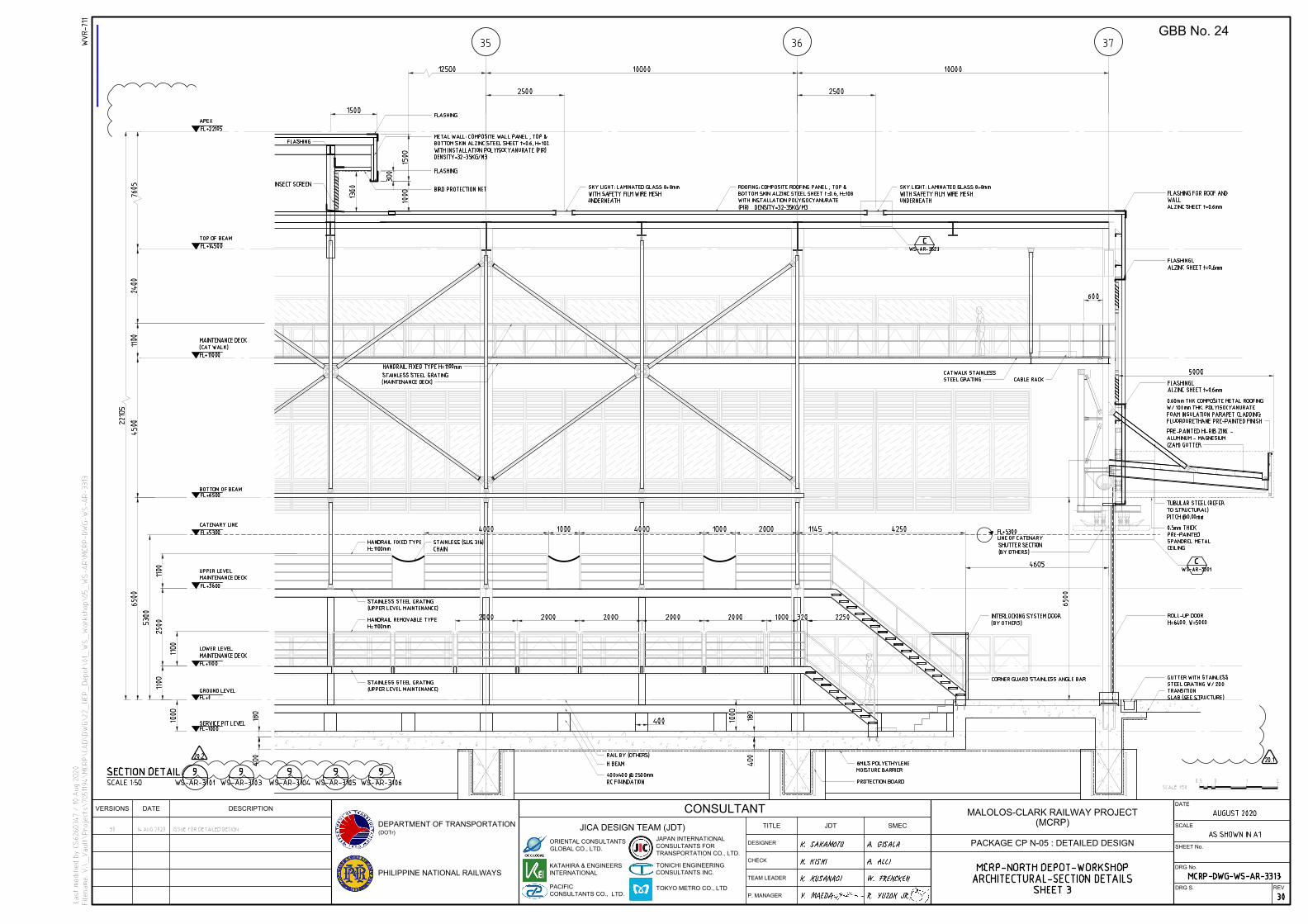
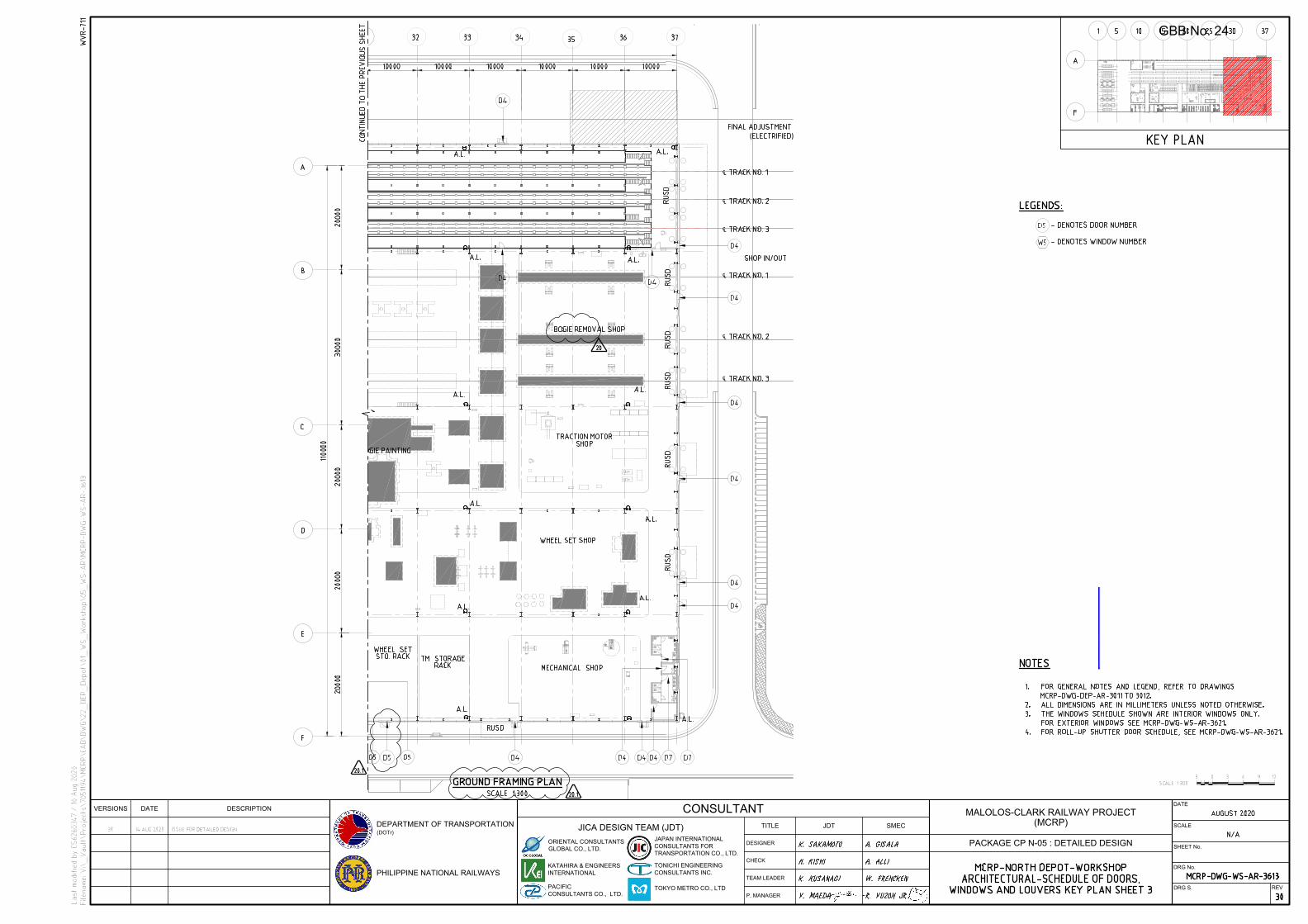
℄
℄
℄
℄
℄
℄
PHILIPPINE NATIONAL RAILWAYS
TEAM LEADER
P. MANAGER
SMEC
VERSIONS DATE DESCRIPTION
CONSULTANT
TITLE
CHECK
DESIGNER
JICA DESIGN TEAM (JDT)
DATE
SCALE
SHEET No.
DRG No.
JAPAN INTERNATIONAL
CONSULTANTS FOR
TRANSPORTATION CO., LTD.
DRG S.
ORIENTAL CONSULTANTS
GLOBAL CO., LTD.
DEPARTMENT OF TRANSPORTATION
(DOTr)
PACIFIC
CONSULTANTS CO., LTD.
TONICHI ENGINEERING
CONSULTANTS INC.
KATAHIRA & ENGINEERS
INTERNATIONAL
JDT
TOKYO METRO CO., LTD
REV
MALOLOS-CLARK RAILWAY PROJECT
(MCRP)
PACKAGE CP N-05 : DETAILED DESIGN
GBB No. 24
Asus
IFC
Related Documents