The Magnetic Fusion Program in China ——Roadmap and Progress Presented by Yuanxi Wan 1, 2 1 University of Science and Technology of China, Hefei, China 2 Institute of Plasma Physics, CAS, Hefei, China E-mail: [email protected] or [email protected] December 16-17, 2014 35 th FPA , Washington USA

Welcome message from author
This document is posted to help you gain knowledge. Please leave a comment to let me know what you think about it! Share it to your friends and learn new things together.
Transcript

The Magnetic Fusion Program in China ——Roadmap and Progress
Presented by Yuanxi Wan1, 2
1 University of Science and Technology of China, Hefei, China 2 Institute of Plasma Physics, CAS, Hefei, China
E-mail: [email protected] or [email protected]
December 16-17, 2014
35 th FPA , Washington USA

Content
Road Map of MFE in China
Strategy and Progress
Summary

Background
China is facing serious energy problem now and future
Burning plasma has been achieved on JET,TFTR, (JT-60)
Some progress of MF research has been achieved
before China join ITER project
Government made big decision to join ITER project
Significant progress of MF research has been achieved
since China join ITER project
Roadmap of MFE development in China

4
A national integration design group for CFETR was
founded by MOST at 2011
The progress on the conceptual design and some
R&D of CFETR has been achieved
A special group for drafting the MF roadmap in
China has been organized by MOST few months ago
According to the roadmap it is hoped the proposal for
CFETR construction can be approved soon

5
The Road Map
of MFE development in China ( the first draft )
by the roadmap draft group

6
1. 2006-2045: Join and fully support the construction, operation
and experiments of ITER; enhance the support for pe-xperimentson EAST, HL-2M and J-TEXT;
2. 2020: Start to construct the Chinese Fusion Engineering Testing Reactor (CFETR) .
3. 2030: Complete the construction of CFETR ( Pf ~200MW and test
of SSO and tritium self-sustained )
4. 2040: Complete the upgrade of CFETR ( Pf ~1 GW, Qeng > 1 ).
5. 2050-2060: Complete the construction of Prototype Fusion Power Plant (PFPP) (~1GWe, Power Plant Validation)
Milestones of the Roadmap

2015 2020 2025 2030 2035 2040 2045 2050 2055 2060
Disruption mitigation, basic plasma
Advanced divertor, high power H&CD, diagnostics
Advance PFC, steady-state advanced operation
Phase I :Q=10, 400s, 500MW, Hybrid burning plasma
Phase I I:Q=5, 3000s, 350MW, steady-state burning plasma
(~2021)
I:Q=1-5, steady state, TBR>1, >200MW, 10dpa
II:DEMO validation, Q>10, CW, 1GW, 50dpa
(2030 start operation)
1GWe, PowerPlant Validation
(~2050)
Roadmap for ChineseRoadmap for ChineseMFE DevelopmentMFE Development

By superconducting-tokamak and bootstrap current
plus the external CD to achieve the SS burning
plasma operation
By the efficient breeding blanket and advanced
tritium factory technology to achieve the Tritium
self-sustained.
Technical Route adopted by the Roadmap

9
1. To achieve and sustain the high performance burning plasma to
be SSO or long pulse with high duty cycle time in fusion reactor;
2. Tritium should be self–sustainable by blanket and high efficient
T- plant;
3. The materials of first wall and blanket should have suitable live
time under the high heat load and flux fusion neutron irradiation ;
4. High Efficient electricity generation on fusion reactor ( Qeng > 1 )
5. Reliability, RH, Nuclear Safety and Environmental Impact
( License );
6. Overall Integrated design of fusion reactor.
The main challenges
Content
Road Map of MFE in China
Strategy and Current Progress
Summary

Strategy for MFE development in China
Fully support ITER project to be success
Enhance the support on domestic research
which is related with the missions of the
roadmap;
fully support the further design and R&D
of CFETR to insure the roadmap can be
realization

Progress of the experiments on
EAST, HL-2A and J-TEXT

2015 2020 2025 2030 2035 2040 2045 2050 2055 2060
Disruption mitigation, basic plasma
Advanced divertor, high power H&CD, diagnostics
Advance PFC, steady-state advanced operation
Phase I :Q=10, 400s, 500MW, Hybrid burning plasma
Phase I I:Q=5, 3000s, 350MW, steady-state burning plasma
(~2021)
I:Q=1-5, steady state, TBR>1, >200MW, 10dpa
II:DEMO validation, Q>10, CW, 1GW, 50dpa
(2030 start operation)
1GWe, PowerPlant Validation
(~2050)
Roadmap for ChineseRoadmap for ChineseMFE DevelopmentMFE Development

HL-2A is upgrading to HL-2M
in SWIP

EAST: ITER/CFETR pre-experiments

NBI-1
NBI-2
LHCD-1
LHCD-2
ICRH-1
ICRH-2
ECRH-1
H & CD capabilities on EAST allow truly advanced SS operations
2012: 10MW2014: 26MW2016:26+8MW
ITER-like RF-dominant H&CD, capable to address key issues of high performance SS operations

Progress of CFETR
conceptual design

2015 2020 2025 2030 2035 2040 2045 2050 2055 2060
Disruption mitigation, basic plasma
Advanced divertor, high power H&CD, diagnostics
Advance PFC, steady-state advanced operation
Phase I :Q=10, 400s, 500MW, Hybrid burning plasma
Phase I I:Q=5, 3000s, 350MW, steady-state burning plasma
(~2021)
I:Q=1-5, steady state, TBR>1, >200MW, 10dpa
II:DEMO validation, Q>10, CW, 1GW, 50dpa
(2030 start operation)
1GWe, PowerPlant Validation
(~2050)
Roadmap for ChineseRoadmap for ChineseMFE DevelopmentMFE Development

Bt= 4.5 -5T;
Ip= 8-10MA;
R = 5.7m;
a = 1.6m;
К= a/b=1.8~2.0;
βN ~2.0 ; q 95 ≥3;
Triangularity δ= 0.4-0.8;
Single-null diverter;
Neutron wall loading ≈0.5MW/m2;
Duty cycle time = 0.3-0.5;
TBR ~ 1.2
Possible upgrade to R~5.9 m, a~2 m, Bt= 5T, Ip~14 MA
CFETR Machine Configuration

Operation mode A B C D E ITER
-SSUpgrade
Ip(MA) 10 10 10 8 8 9 15Paux(MW) 65 65 65 65~70 65 59 65q95 3.9 3.9 3.9 4.9 4.9 5.2 3.9W(MJ) 171~174 193 270~278 171 255 287 540PFus (MW) 197~230 209 468~553 187~210 409 356 1000Qpl 3.0~3.5 3.2 7.2~8.5 2.7~3.2 6.3 6.0 15Ti0(keV) 17.8~18.5 29 19.8~20.8 20.6~21 21 19 25Nel(1020/m3) 0.75 0.52 1.06 0.65 0.94 1nGR 0.6 0.42 0.85 0.65 0.95 0.82 0.85βN 1.59~1.62 1.8 2.51~2.59 2 2.97 3.0 2.7βT(%) ~2.0 2.3 3.1~3.25 2 2.97 2.8 4.2fbs(%) 31.7~32.3 35.8 50~51.5 50 73.9 48 47τ98Y2(s) 1.82~1.74 1.55 1.57~1.47 1.37 1.29 1.94 1.88PN/A(MW/m2) 0.35~0.41 0.37 0.98 0.33~0.37 0.73 0.5 1.38ICD(MA) 3.0~3.1 7.0 2.45 4.0 2.76 3.0H98 1 1.3 1.2 1.3 1.5 1.57 1.2Tburning(S) 1250 SS 2200 M/SS SS ??
Key parameter investigation
ThPO-3 B. Wan, etc.

Front U-shaped structure
Front inner panel
Back inner panel
Back U-shaped structure
Toroidal flexible support
CS3U
CS2U
CS1U
CS1L
CS2L
CS3L
11.42
9.7878.1566.525
4.8943.263
1.631
1.631
4.894
stray field from 2GS to 20GS
Z (m
)
R (m)
The magnetic flux distribution. The maximum B of CS coil is about 12 T
The maximum of stray field in plasma area is about 14 GS
Tie PlateTightening block
Bottom support structure
CFETR Magnet System

- A torus shaped double wall structure;- To provide high vacuum for plasma and
primary radiation confinement boundary;- To support in-vessel components- Important space of the Vacuum Vessel for
plasma;- First safety barrier;
T-ribs
Outer-shell
Inner-shellUpper port
Equatorial port
Lower port
CFETR Vacuum Vessel

CFETR Blanket

CFETR Divertor
Three configurations: ITER-Like, Snowflake and Super X.New structure with ‘vertical reflector’: inner baffle, inner particle reflector, inner target, dome, outer target, out particle reflector and outer baffle.Cassette structure for easier RH handling. Shared cassette between snowflake and ITER-like divertor.Small incident angle ~16°. Closed ‘V’ shape configuration.Pumping gap between dome and targets.Divertor cooling scheme was developed. Support design compatible with RH was finished.Snowflake divertor design

CFETR tokamak assembling

CFETR blanket with the RH


Progress of CFETR Conceptual design
1. physics investigation2. Tokamak reactor integrated desing3. H&CD 4. CODAC 5. Daignostics6. SC magnets

Progress of CFETR Conceptual design
1. Layout design andsystem Integration
2. Plasma physics and technology
3. Superconductingmagnet and cryogenics
4. Vacuum vessel &vacuum system
5. In-vessel components:- blanket & diverter
6. Heating & CurrentDrive system
7. Diagnosis & CODAC8. Electrical power &
control system9. Fuel circulation system
& waste disposal10. Radiation protection &
safety, RAMI11. Remote control and
maintenance system12. Auxiliary supporting
system13. Project management
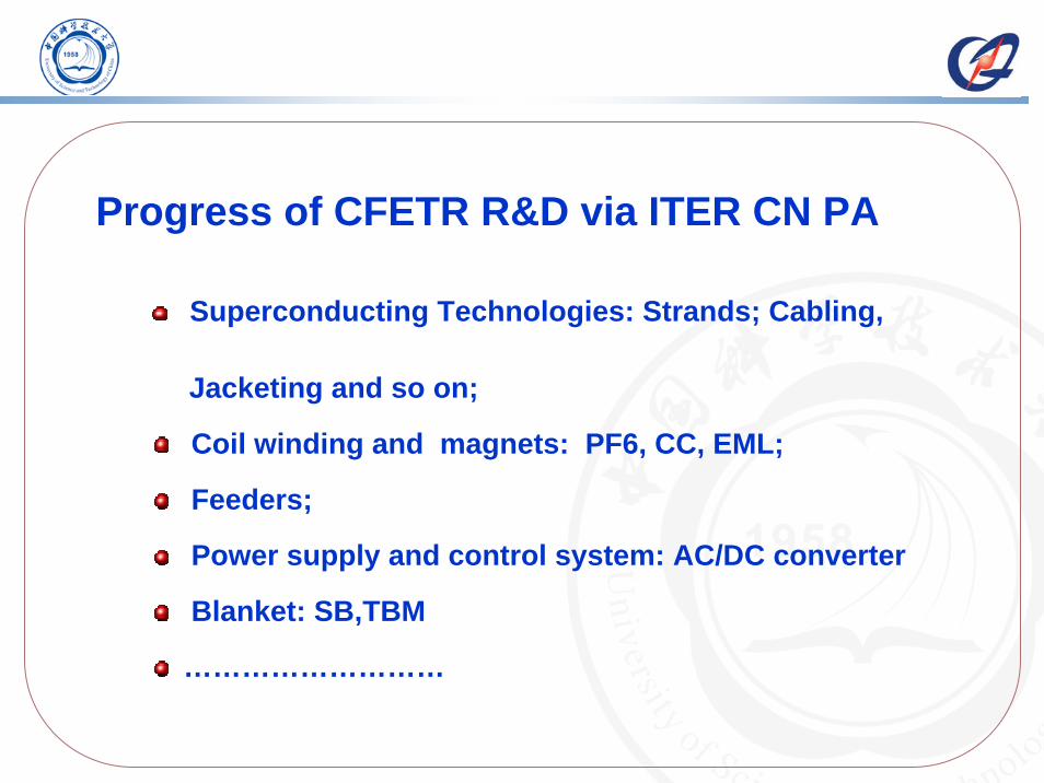
Progress of CFETR R&D via ITER CN PA
Superconducting Technologies: Strands; Cabling,
Jacketing and so on;
Coil winding and magnets: PF6, CC, EML;
Feeders;
Power supply and control system: AC/DC converter
Blanket: SB,TBM
………………………

by Western Superconducting Technologies Co., Ltd.
Progresses of CN PA also for CFETR R&D

TF conductor arriving Japan
TF conductor arriving Italia PF conductor arriving ITER siteCeremony for 1st shipping
900m CICC jacket line
Conductor fabrication process
3 jacketing lines and conductor integrating facility were set up in ASIPP.
2 parallel buildings were set up for conductor integrating, NDE, cabling, acceptance test.
All conductors produced by CN DA were accepted with their first tests.
The first ITER oversized components, PF5 conductor, arrived at ITER site in June.
Progress of Conductor PA
Progresses of CN PA also for CFETR R&D

Significant progresses of ITER HTC feeder achieved31 Feeder systems. No two pieces are identical.>1000 tons, >tens thousands of different parts.Feeder PA is on stage II. Critical technologies were developed in ASIPP. Mock-ups will be developed before production. 72 HTS current leads (including prototypes and back-ups) will be supplied. 10/52/68kA three types current leads are designed and developed. 7 mock-ups were finished.
Overview of Feeder system in ITER
PF5 in-cryostate feeder trial Verification of Busbar
Progresses of CN PA also for CFETR R&D

PS Test Facility can meet all ITER PS test requirement
Progresses of CN PA also for CFETR R&DProgress of power supply PA:

Progresses for CFETR R&D by EDP
1/16 VV mock-up1/6 CS magnetTritium technologies: T-Plant, Breeding materialMaterials : CLAM; first wall- W, neutron sourceRH ………………………
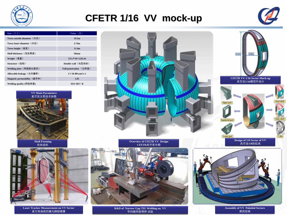
CFETR 1/16 VV mockCFETR 1/16 VV mock--upup
VV Main Parameters真空室主要技术参数
VV Main Parameters真空室主要技术参数
R&D of Narrow Gap TIG Welding on VV窄间隙焊接预研试验
R&D of Narrow Gap TIG Welding on VV窄间隙焊接预研试验
Shell Forming 壳体成形
Shell Forming 壳体成形
Laser Tracker Measurement on VV Sector真空室扇段的激光跟踪测量
Laser Tracker Measurement on VV Sector真空室扇段的激光跟踪测量
Overview of CFETR VV DesignCFETR真空室全貌
Overview of CFETR VV DesignCFETR真空室全貌
Assembly of VV Poloidal Sectors扇段组装
Assembly of VV Poloidal Sectors扇段组装
Design of 1/8 Sector of VV真空室1/8段组成
Design of 1/8 Sector of VV真空室1/8段组成
CFETR VV 1/16 Sector Mock-up真空室1/16模型件设计
CFETR VV 1/16 Sector Mock-up真空室1/16模型件设计
Size(尺寸) Value (值)
Torus outside diameter(外径) 19.5m
Torus inner diameter(内径) 5.74m
Torus height(高度) 11.4m
Shell thickness(壳体厚度) 50mm
Weight(重量) 155.3*16=1242.4t
Structure(结构) Double wall(双层壳体)
Welding joint(焊接接头要求) Full penetration (全焊透)
Allowable leakage(允许漏率) 1×10⁻⁸Pa·m3·s-1
Magnetic permeability(磁导率) 1.05
Welding quality (焊接质量) ISO-5817 B

1/32 section mock up of the CFETR VV

38
One Section(1/6) of CFETR CS Model Coil
Nb3Sn Coil
NbTi Coil
Design Parameters of CFETR CS Model Coil
Max. field 12 T
Max. field rate 1.5 T/s
Inner radius 750 mm
Coil structure Hybrid magnetInner:Nb3Sn coilOuter:NbTi coil
Conductor type Nb3Sn CICC NbTi CICC
Coil ParametersCoil Parameters
Nb3Sn Conductor NbTi Conductor

Formation of tritium permeation barrier (TPB) on vessels and pipes for tritium confinement is the first choice to minimize tritium loss and its environmental radiological risk.A series of oxides, aluminides, carbides and nitrides of TPB have been studied, and high tritium permeation reduction factor (PRF) can be obtained.
Tritium permeation barrier
TPB type Oxides Carbides and nitrides Compounds
Materials Al2O3,Cr2O3,Er2O3,(Ar,Cr)2O3 TiN,TiC,SiC Al2O3/FeAl,Er2O3/SiC,SiC/TiC@Al-Cr-O
Process chemical and physical process physical process chemical and physical process
PRF 400~10000 >1000 300~3000
Progress of preparation of solid tritium breeder CAEP independently developed a frozen- wet preparation technology of solid tritium breeder, currently has a preparation capability of kilograms in lab.
Phase purity ~99%
Preparation level of Kg class
Li4SiO4 pebble Compressive strength(a.v.) >20 N
D.Zhu, et al. J. Nucl. Mater, 2010X. Gao, et al. J. Nucl. Mater, 2012
CFETR T-plant technologies
X. Gao, et al. J. Nucl. Mater, 2012
Li4SiO4pebble

Nominal compositions: 9Cr1.5W0.2V0.15Ta0.45Mn0.1C4.5 ton smelting with good control of main compositions
High-dose neutron irradiation experiments( Spallation source ~20dpa )( High Fluence Engineering Test Reactor ~2dpa )
Fabrication of test blanket module (TBM) ( 1/3 scale P91 TBM, 1/3 scale CLAM first wall )
Properties of CLAM stthose of the other RAFM
eel is comparable with s, e.g. Eurofer97, JLF-1.
Irradiation properties and TBM Fabrication
Production and properties
W material study scope: W alloy; W coating; W/Cu component
Deposition rate: 0.2-1mm/h
W/Cu
W/OFHC-Cu
W/FGM-W/Cu
W/RAFM Steel
W/graphite
(Chemical vapor deposition) CVD-W Conventional Powder Metallurgy Samples: High Purity W, W-TiC
Relative density :
1# 2# 3# 4#
94.8% 95.1% 94.5% 94%
High Purity WW-TiC
SPS Samples: Pure W, W-TiC, W-La2O3
Pure W Φ80×10mm W-TiC Φ80×10mm
rolling direction
rolling direction
High heat-fluxtest facility
1/3 P91 TBM 1/3 CLAM FW
Materials research: LAM; first wall-W
1/3 CLAM FW 1/3 P91 TBM 1/3 CLAM FW
1/3 P91 TBM 1/3 CLAM FW

CFETR RH strategy

Some Achievements of RH project
~ 80%

RH test on EAST

RH test on EAST

2012- 2014: provide the engineering conceptual design
of CFETR
Complete two proposals in 2015 :
1. more key R&D items for CFETR
2. Construction proposal for CFETR
It is hope that CFETR can be approved soon
and to be constructed around 2030.
CFETR Further plan

More R&D
Design and R&D strategy for CFETR

The MFE roadmap is under discussion
in China
Integrated Design and R&D of CFETR
are in progress
The wide international exchange and
collaboration for CFETR are welcome !
Summary

Thanks for your attention !
CFETR-ASSEMBLY (1).mov
Related Documents


