THE SOUND ENGINEERING MAGAZINE OCTOBER 1972 $1.00 111r11111111111111 T P OPA ,pt / \"?,ta )y .,/ : ; .ts3 N:V;J A " r-1.1 ; *4- www.americanradiohistory.com

Welcome message from author
This document is posted to help you gain knowledge. Please leave a comment to let me know what you think about it! Share it to your friends and learn new things together.
Transcript
THE SOUND ENGINEERING MAGAZINE
OCTOBER 1972 $1.00
111r11111111111111
T P OPA
,pt / \"?,ta )y .,/ :
;
.ts3 N:V;J A
" r-1.1 ;
*4-
www.americanradiohistory.com

Solve 7 problemi...in deeoncJf.
Something totally new to add to your bag of tricks! We call them Plug -in Problem Solvers. They're designed to provide seven common modifications in microphone and sound system setups without soldering or rewiring -just plug them in! The Model Al 5A Microphone Attenuator that prevents input overload; Model A15PR balanced line Phase Reverser; and A15HP High Pass and A15LP Low Pass Filters to modify low and high frequency response; A15PR Presence Adapter to add brilliance; A15RS Response Shaper to filter sibilance and flatten response; and the A15LA Line Adapter that con- verts low impedance microphone inputs to line level inputs. Carry them on every job. It's a lot easier than carrying a studio console with you!
Shure Brothers Inc., I 222 Hartrey Ave., Evanston, Ill. 60204. JA
Circle 10 on Reader Service Card
H V R
www.americanradiohistory.com

COMING NEXT MONTH
John Woram abandons his usual column to write a feature article on his design (and use) of a switching system that permits the use of the same Dolby units for several machines of different track configurations. It's a true how-to- have -your- cake -and -eat- it -too story.
Walter Jung is back with his AUTO- MATING THE AUDIO CONTROL FUNC- TION. In part 4 you will discover a brand new kind of integrated circuit, the Harris Semiconductor PRAM and its application to audio switching sys- tems.
Marshall King, our man about t.v. audio has written a provocative article with the title (ONE MAN'S OPINION) ON THE BUSINESS OF HEARING. We think you will find his comments im- portant and worthy of serious con- sideration.
And there will be our regular col- umnists: George Alexandrovich, Nor- man H. Crowhurst, Martin Dickstein. Coming in db, The Sound Engineering Magazine.
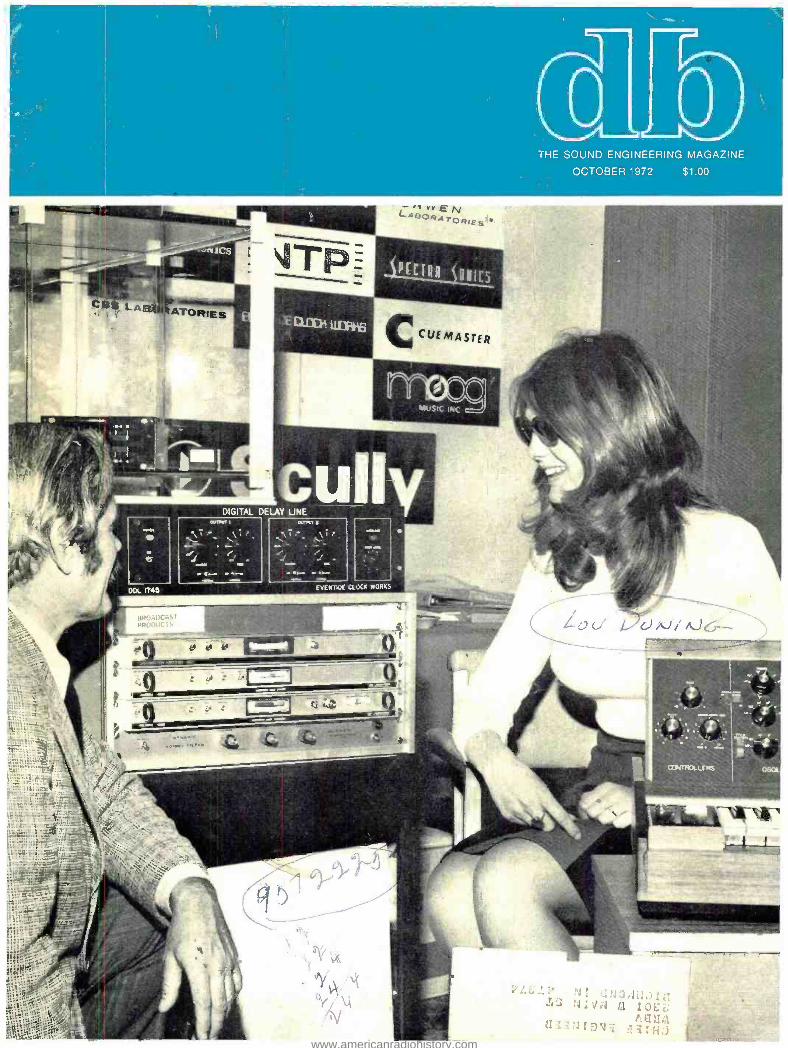
ABOUT THE COVER
Ham Brosious who assembled our story on APRS '72, appearing on page 34, is seen in discussion with a typi- cal (his word) English engineer. The booth is that of Feldon Audio Ltd., of London, England.
ob: THE SOUND ENGINEERING MAGAZINE
OCTOBER 1972 VOLUME 6, NUMBER 9
17 NEW YORK AES CONVENTION - PICTURE GALLERY
23 BUILD A DIGITAL READOUT ELECTRONIC STOPWATCH Ralph E. Hornberger
28 AUDIO VISUALS UNDER THE STARS Martin Dickstein
34 APRS '72 Ham Brosious
2
8
14
38
THE AUDIO ENGINEER'S HANDBOOK George Alexandrovich
THEORY AND PRACTICE Norman H. Crowhurst
THE SYNC TRACK John Woram
SOUND WITH IMAGES Martin Dickstein
40 BOOKCASE
41 CLASSIFIED
42 PEOPLE, PLACES, HAPPENINGS
db is listed in Current Contents: Engineering and Technology,
Robert Bach PUBLISHER Bob Laurie
ART DIRECTOR A. F. Gordon
CIRCULATION MANAGER
Eloise Beach ASST. CIRCULATION MGR.
Larry Zide EDITOR John Woram ASSOCIATE EDITOR Marilyn Gold COPY EDITOR
Richard L. Lerner ASSISTANT EDITOR
GRAPHICS Crescent Art Service
db, the Sound Engineering Magazine is published monthly by Sagamore Publishing Company, Inc. Entire contents copyright © 1972 by Sagamore Publishing Co.. Inc., 980 Old Country Road, Plainview. L.I., N.Y. 11803. Telephone (516) 433 6530. db is published for those individuals and firms in professional audio - recording, broadcast, audio -visual, sound reinforcement, consultants. video recording, film sound, etc. Appli- cation should be made on the subscription form in the rear of each issue. Subscriptions are 56.00 per year ($7.00 per year outside U. S. Possessions, Canada. and Mexico) in U. S. funds. Single copies are 51.00 each. Controlled Circulation postage paid at Harrisburg, Pa. 17105. Editorial, Publishing, and Sales Offices: 980 Old Country Road. Plainview, New York 11803. Postmaster: Form 3579 should be sent to above address.
www.americanradiohistory.com

George Alexandrovich
THE AUDIO ENGINEER'S HANDBOOK
Transients in audio systems
Almost every system is either sus- ceptible to some sort of transients or has elements capable of producing sudden current changes which can leak into the main audio channels. It is our desire to see that no transients exist in the audio systems. This can be easily accomplished in the sys- tems which are mass produced, where wire dressing and component layout can be experimentally determined. However, as requirements change, more and more systems are being custom made, meaning that there are no experimental models. The first model is the final model -there is no time and no money allocated to ex- periment. The same unit has to per- form, has to look good, and whoever builds it can not lose money on it. (I am referring to an audio manufactur- ing firm or contractor.)
This kind of the system has many switches, relays, and jacks- each one a potential source of transients. In engineering such a system, most engi- neers are guided by a standard set of rules which help to prevent trans- ients, generally referred to as pops and clicks. Less experienced techni- cians sometimes allow mistakes to happen -which may cost more in time than one can afford. For instance, instead of running separate wires for the relay circuits and amplifier cir- cuits, he may end in rewiring the whole console. In the best case, a "fix" would have to be used in every control and amplifier circuit to sub- due pops and clicks to a tolerable level. And the big question is what is tolerable?
On one occasion, in order to guide ourselves in specifying and testing audio systems we called the Federal Communications Commission, the NAB, IEEE, and AES. Our question -what are the standards for tran- sients in communications ?, what are the limits -and do you have any sug- gested measuring techniques? These were left unanswered. There are no standards concerning transients. For instance the FCC told us that tran- sients should be below audibility at normal listening levels. What are nor- mal listening levels. One level is ac-
c ceptable in a broadcasting studio
where the monitor amplifier may be a 15 watt unit, while in the recording studio there may be several 100 -watt amplifiers producing sound pressure levels beyond safe levels for human hearing.
Specifying transients by referring the transient levels to the noise levels is also vague. Some systems have noise level only few dB above the theoretical minimum, while others may be 10 -20 dB higher.
Transients can be tricky. Some may have very steep fronts and fast de- cays, others may have gentle fronts with slow decays. If we display them on the scope, some will appear as sharp spikes, others just as a change of base line position. Sharp transients usually have very high voltage peaks but very little power. Others may have very low voltage peaks, but a
lot of power. The amount of power contained in the transient is equal to the area contained by the waveform
advertisers index
Acoustic Research 3
Altec 7 Audio Distributors 33 Auditronics 37 Automated Processes . 26, 27 BHK Electronics 12 Duncan Electronics . Cover 4 Electro -Voice 4 Fairchild Sound 19, 20 Gately Electronics 22 Gotham Audio 15 ITI 16 Neve 35 Quad -Eight 30, 31 Sansui 9, 10, 11
Shure Cover 2 Soundcraftsmen 12 Spectra Sonics 5
Telex 6 Timekeeper Cover 3
UREI 13
Windjammer 21
0 THE SOUND ENGINEERING MAGAZINE
SALES OFFICES
New York 980 Old Country Road Plainview, N.Y. 11803
516 -433 -6530
Dallas Roy McDonald Associates, Inc.
Semmons Tower West Suite 714
Dallas, Texas 75207 214- 637 -2444
Denver Roy McDonald Associates Inc.
846 Lincoln Street Denver, Colorado 80203
303 -825 -3325
Houston Roy McDonald Associates,. Inc.
3130 Southwest Freeway Houston, Texas 77006
713 -529 -6711
Los Angeles Roy McDonald Associates Inc.
1313 West 8th Street Los Angeles, California 90018
213- 483 -1304
Portland Roy McDonald Associates, Inc.
2305 S. W. 58th Avenue Portland, Oregon 97221
503 -292 -8521
San Francisco Roy McDonald Associates, Inc
625 Market Street San Francisco, California 94105
415- 397 -5377
www.americanradiohistory.com

The AR Laboratory Standard Transducer
ACCURACY AND FLEXIBILITY: The AR -LST offers a total of six different energy profiles - all accurately known and repeatable at the turn of a switch, which is located on the front of the cabinet. This permits a degree of control and precision that is usually found only in electronic equipment.
FLAT ENERGY CAPABILITY: The AR -LST is capable of a flat energy output characteristic that, in our judgement, establishes a new state of the art. The graph shown above represents the acoustic power output produced by the AR -LST with its control set to the "flat" position. The horizontal line below 500 Hz indicates the relative woofer level.
A speaker for professional use from Acoustic Research
.t 1000 21.11 .5001
LOW DISTORTION: As with the AR -3a, harmonic distortion measurements down to the lowest audible frequencies are, to the best of our knowledge, the lowest of any loudspeaker system available.
WIDE DISPERSION: AR's hemispherical dome tweeters produce exceptionally smooth, wide dispersion of midrange and high frequencies, even in rooms or studios that are acoustically rather dead.
POWER HANDLING: Multiple drivers for midrange and high frequencies enable the AR -LST to handle power levels significantly higher than AR's finest speakers designed primarily for home use.
Detailed information on the AR -LST is available on request. Mail the coupon below.
AI Acoustic Research, Inc. 24 Thorndike Street Cambridge, Massachusetts 02141, Dept. DB -10
Please send the booklet describing the AR -LST to
NAME
ADDRESS
Circle 13 on Reader Service Card w
www.americanradiohistory.com

One of a series of brief discussions by Electro -Voice engineers
WILLIAM RAVENTOS Marketing Manager Pro Audio Products
Several years ago, Electro -Voice Introduced a
windscreen material for microphones we call Acoustifoam that offered a substantial im- provement over the bulky silk and wire con- structions then in use.
Recently a number of windscreens similar in appearance to Acoustifoam have arrived on the market. But not all plastic windscreens are alike. A number of characteristics of foam plastic can strongly influence the effectiveness of the material as a windscreen and the per- formance of the microphone hidden inside.
The material used in Acoustifoam is carefully controlled for density and porosity. and goes through a number of extra processing steps required to meet the standards set for it. In addition to reducing the sounds of air turbu- lence near the microphone (thus serving as an effective windscreen) it must have no appre- ciable effect on microphone frequency re- sponse, level, or polar response at any fre- quency.
The passive nature of this material is assured by the extra processing of the basic foam after it is molded. Look closely at most ordi- nary foam (and even some foam sold as wind. screen material) and you will see bright high- lights from tiny flat surfaces that cover many of the pores in the foam. Each closed pore in the foam acts as a reflector of sound, and as a barrier, and will significantly alter micro- phone response and even output level in ex- treme cases. High frequency roll off of up to 20 db at 10 kHz has been measured with some foams.
The method used to "open up" these closed pores is called reticulation, and is a chemical treatment that dissolves the very thin pore walls without substantially altering the heavier foam connecting material. Another test for foam is to blow gently through the material. If any resistance is felt, the foam is insufficiently porous for windscreen use.
Pore size (after reticulation) is also a signifi- cant part of windscreen design and can have an effect on the ability of a windscreen to sat- isfactorily reduce wind noises to the lowest possible value. Thickness of the windscreen itself also has an important bearing on its wind noise reduction capability. Foam of in- sufficient thickness will prove less effective in controlling wind noise.
While windscreens may seem simple and un- complicated devices, in truth their design must match the sophistication of the microphone in- side if full benefit is to be obtained from both microphone and windscreen.
For reprints of other discussions in this series, or technical data on any E -V product, write:
ELECTRO- VOICE, INC., Dept. 10238D 686 Cecil St., Buchanan, Michigan 49107
S-Leteroksz a GULTON subsidiary
Circle 14 on Reader Service Card
and the baseline .
Modern technology --- -using directly - coupled amplifier circuits and oper- ational amplifiers capable of ampli- fying signals from d.c. to MHz range create conditions where transients are harder to subdue and isolate. But at the same time we have better and cheaper tools to control it. We can afford to put a regulator at each am- plifier and still not go broke.
But before we go into remedies let us review the causes of transients.
1. Turning on the power supply creates a d.c. wave front until all amplifiers stabilize and all capacitors get charged.
2. Changing power consumption by turning on tally lights, turning on additional amplifiers or circuits.
3. Turning on or off relays or other inductive circuits.
4. Changing the load on the ampli- fier output or input.
The first condition depends greatly on the construction of the power sup- ply and the amplifiers. If the design is such that d.c. rises slowly and each amplifier has each own decoupling circuit -damping and smoothing this wavefront -then a transient will not be detectable.
The second condition exists in al- most any system and is hardest to control. One of the surest ways to control it is to use a separate power supply system for control and light circuits from amplifier or audio lines. If you are forced to use the same power supply then it should have low source impedance and separate lines should originate from the output ter- minals of the power supply. If the amplifiers have good decoupling, chan- ces are you may supply all circuits from the same line without creating transients. Electrolytic capacitors in decoupling networks may have enough capacity to store enough charge to keep the amplifier voltage constant while the supply line voltage changes up or down. Voltage regulators on each amplifier can assure complete isolation of the amplifier from the transient carrying the supply line. The only way for such an amplifier to sense and amplify a transient would be if inductive or capacitive coupling exists between the parts of the am- plifier and the supply line.
The third condition happens when relays or inductive circuits are turned on or off. It is the hardest one to combat because most of the time re- lays carry audio, and the proximity of the relay coil to the audio lines creates inductive coupling which is hard to isolate. We all know that at the instant when the relay coil is con- nected to the power line its imped- ance is very high as long as the cur-
47µf
RELAY COIL 10Sí
E o
Figure 1. This is the best method to re- duce the sharp spike an inductor creates.
rent increases. As soon as the cur- rent achieves its maximum value im- pedance drops to the value of the d.c. resistance. Opening of the d.c. cir- cuit creates a sudden change in the supply current in the power line- but the coil experiences a sudden change in magnetic flux which cre- ates very high voltage across the winding. The theory of this phenom- enon is complicated and is not worth analyzing now. However, we should know that this so- called back EMF (electro- motive force) created by the opening of the electric circuit con- taining inductor has to be eliminated.
This is accomplished by connecting a diode across the inductor. This diode is connected so that the supply vol- tage reverse biases it. Back EMF is opposite in polarity to the supply voltage and the diode conducts these currents, creating the short between the coil and the diode.
But a diode is not always enough to reduce the sharp spike an inductor creates. Many may suggest a com- bination of diode and capacitor, but a capacitor only creates a tank cir- cuit capable of resonating at certain frequency -and at the time current is disconnected from the coil, dying os- cillations set in. This effect may be more harmful than just one fast spike.
My method as shown in FIGURE 1
is not new, but not many use it the same way. It consists of using a re- sistor and capacitor at the switch, turning the circuit on and off. Con- necting the 10 -ohm resistor in series with the switch and the capacitor across both the resistor and the switch provides a gentle current change when turning the circuit on and off, and reduces the transient peak manyfold. Values of the capacitor and the resis- tor may vary with different inductors but the principle works just the same. This method is only as good as engi- neering on the rest of the system. It goes without saying that if (with this noise suppression circuit) one con- nects the amplifier into the ground side (or negative) of the circuit - both have same common ground - then all efforts may end up in vain. Also it should be noted that each switch should have its own suppres- sion circuit. If there are 100 relays and 100 switches there should be 100 suppression circuits.
www.americanradiohistory.com
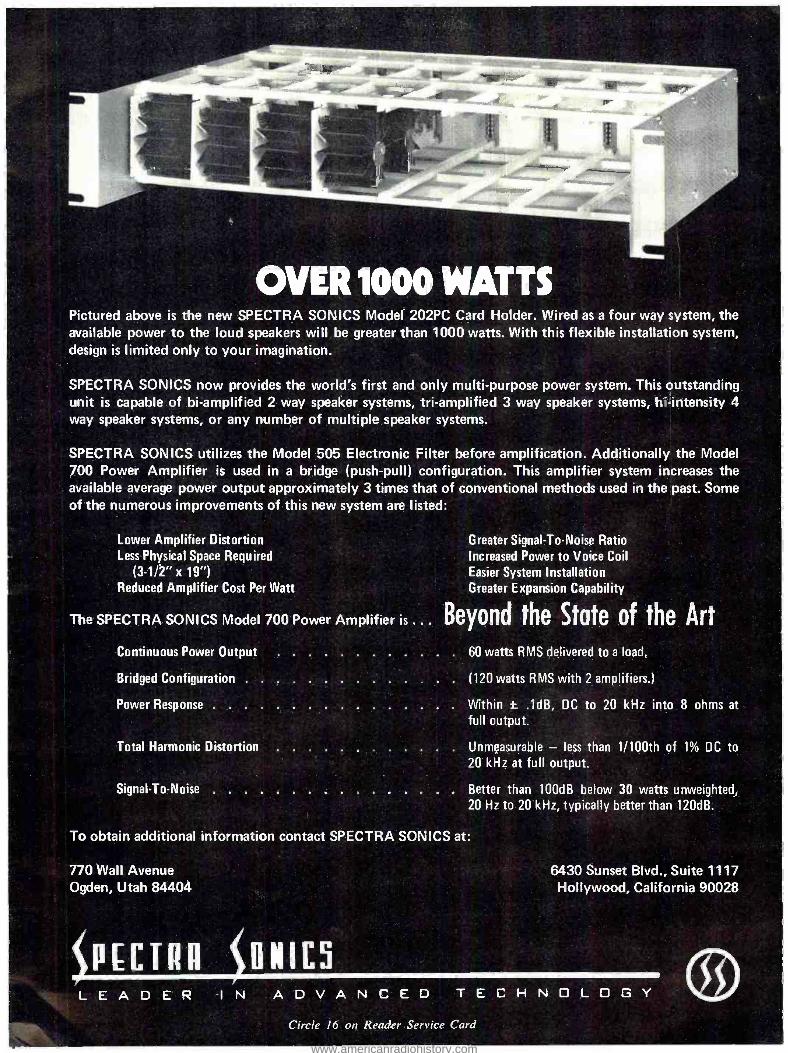
OVER 1000 WATTS Pictured above is the new SPECTRA SON ICS Model 202PC Card Holder. Wired as a four way system, the available power to the loud speakers will be greater than 1000 watts. With this flexible installation system, design is limited only to your imagination.
SPECTRA SONICS now provides the world's first and only multi -purpose power system. This outstanding unit is capable of bi- amplified 2 way speaker systems, tri- amplified 3 way speaker systems, hi- intensity 4 way speaker systems, or any number of multiple speaker systems.
SPECTRA SON ICS utilizes the Model 505 Electronic Filter before amplification. Additionally the Model 700 Power Amplifier is used in a bridge (push -pull) configuration. This amplifier system increases the available average power output approximately 3 times that of conventional methods used in the past. Some of the numerous improvements of this new system are listed:
Lower Amplifier Distortion Less Physical Space Required
(3 -1/2" x 19 ") Reduced Amplifier Cost Per Watt
Greater Signal -To -Noise Ratio Increased Power to Voice Coil Easier System Installation Greater Expansion Capability
The SPECTRA SONICS Model 700 Power Amplifier is ... Beyond the State of the Art Continuous Power Output 60 watts RMS delivered to a load.
Bridged Configuration (120 watts RMS with 2 amplifiers.)
Power Response Within t .1dB, DC to 20 kHz into 8 ohms at
full output.
Total Harmonic Distortion Unmeasurable - less than 1 /100th of 1% DC to 20 kHz at full output.
Signal -To -Noise Better than 100dB below 30 watts unweighted, 20 Hz to 20 kHz, typically better than 120dB.
To obtain additional information contact SPECTRA SON ICS at:
770 Wall Avenue 6430 Sunset Blvd., Suite 1117 Ogden, Utah 84404
PECTRA \llNIC5
Hollywood, California 90028
L E A D E R -IN A D V A N C E D T E C H N O L O G Y
Circle 16 on Reader, Service Card
www.americanradiohistory.com

BETTER HEAR
MUFFS
Audiometric -type transducers make our headphones better. Better than any headphone you've ever tried. You can hear the difference; clear, live, distortion -free sound. But even more important, performance and sound are the same, all day, every day. Because our audiometric -type elements are ab- solutely stable to give you consistent performance at all times.
Originally, we developed audiometric elements for clinical hearing tests and measurements. This required elements that remain totally stable even with changes in temperature or humidity. Sensitive elements that respond efficiently to variances in frequencies and power input. Elements capable of sound reproduction at over 130 dB sound pressure level with very low distortion and without burning up.
Now we've modified and adapted this audiometric trans- ducer element to give you a series of thoroughly professional headphones. Headphones you can rely on for stable per- formance - day in, day out. Clear and undistorted so you can truly monitor sound quality and balance and not just signal presence.
We make two series of professional models to meet your needs Series 1325 for stereo monitoring and series 1320 for communications, with optional noise cancelling boom micro- phone. Try our better hear muffs at better dealers - or write for free information. You'll hear more from Telex. ©
PRODUCTS OF SOUND RESEARCH
L OZZ®
COMMUNICATIONS DIVISION 9600 ALDRICH AVENUE SOUTH MINNEAPOLIS, MINNESOTA 55420
CANADA: DOUBLE DIAMOND ELECTRONICS, LTD., Ontario EUROPE: ROYAL SOUND COMPANY, INC.,
409 North Main Street, Freeport, N.Y. 11520 U.S.A.
Circle 15 on Reader Service Card
Condition four deals with the chang- ing of the amplifier load. Most am- plifiers today are class AB amplifiers. This means that the amplifier draws only as much current as the load re- quires. If there is no load then the current remains the same. A small idling current is present all the time. The difference between class B and class AB is that there is no idling cur- rent in the class B amplifier but it has more crossover distortion than class AB. A class A amplifier always draws the full amount of current re- quired for full output and is there- fore very inefficient. If one watt of power is required from the amplifier (30 dBm) there will be over two watts of power dissipated in heat in the amplifier at all times, even when no signal is fed or amplified.
But getting back to the class AB amplifiers, if we connect loads to the output of the amplifier then we change the power consumption. At the in- stant we connect the load we create the transient. Some circuits have a capacitor to decouple the d.c. of the amplifier from the load. If there is no load connected, this capacitor has no charge. At the time the load is con- nected the capacitor charges, because there is a difference of potential be- tween the load and the output of the amplifier. A transient is created by the additional current requirement and presence of d.c. on the output of the capacitor. This d.c. appears across the load for a short duration but is sufficient to produce a click or pop. Again, decoupling of the amplifier from the power supply is the answer for the power supply section -and a large resistor at least ten times the resistance of the load permanently connected across the amplifier output just to keep the capacitor charged at all times.
What I have just reviewed is not new and is well known to a good number of readers. But some of you may find it helpful in constructing your own systems. This subject re- vived my interest because of the fact that I could not find any specifica- tions nor standards concerning allow- able amount of transients and how they should be measured and classi- fied. I was truly disappointed to learn that in this age of computer -controlled systems -where most of the electrical functions are switching functions - there is no better criterion for defin- ing the allowable amount of transient than just judging it by ear. I sincerely hope that in the nearest future the brains of the audio engineering com- munity will take up the subject of writing the set of standards which could guide us all in evaluating qual- ity of our systems.
www.americanradiohistory.com
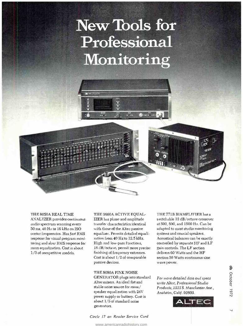
New Tools for Professional Monitoring
THE 8050A REAL TIME ANALYZER provides continuous audio spectrum scanning every 30 ms, 40 Hz to 16 kHz on ISO center frequencies. Has fast RMS response for visual program moni- toring and slow RMS response for room equalization. Cost is about 1/3 of competitive models.
THE 9860A ACTIVE EQUAL- IZER has phase and amplitude transfer characteristics identical with those of the Altec passive equalizer. Permits detailed equali- zation from 40 Hz to 12.5 kHz. High and low -pass functions, 18 dB /octave, permit more precise finishing of frequency extremes. Cost is about 1/2 of comparable passive devices.
THE 8080A PINK NOISE GENERATOR plugs into standard Altec mixers. An ideal flat and stable noise source for room/ speaker equalization with 24V power supply or battery. Cost is about 1/5 of standard noise generators.
Circle 17 on Reader Service Card
THE 771B BIAMPLIFIER has a switchable 12 dB /octave crossover at 500, 800, and 1500 Hz. Can be adapted to most studio monitoring systems and coaxial speakers. Acoustical balances can be exactly controlled by separate HF and LF gain controls. The LF section delivers 60 Watts and the HF section 30 Watts continuous sine wave power.
For more detailed data and specs write Altec, Professional Studio Products,1515 S. Manchester Ave., Anaheim, Calif . 92803.
ALTEÇ V
www.americanradiohistory.com
Norman H. Crowhurst
THEORY AND PRACTICE
The month before last, this column discussed the different ways that sig- nals can be viewed, a little: as a com- posite of audio frequencies, or as a wiggling waveform. There is another connection in which this has relevance. In that discussion we addressed par- ticularly peak level aspects -how dif- ference in shape affects clipping. But it also affects the other end of the dynamic range.
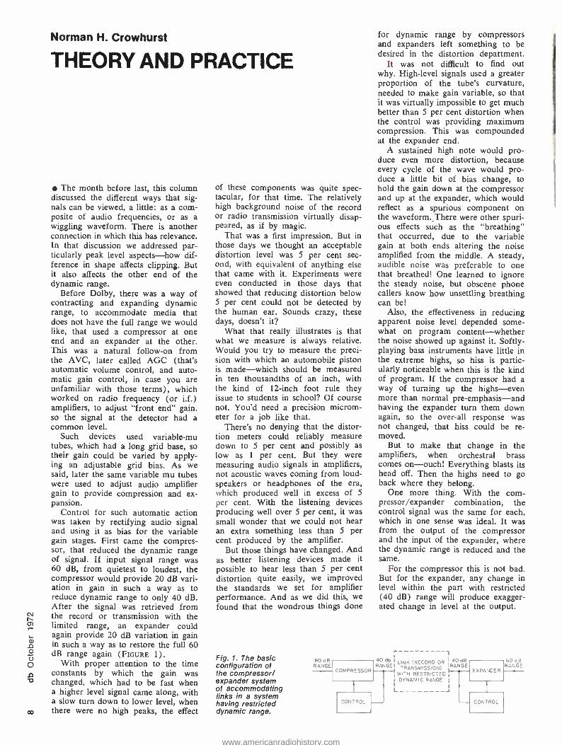
Before Dolby, there was a way of contracting and expanding dynamic range, to accommodate media that does not have the full range we would like, that used a compressor at one end and an expander at the other. This was a natural follow -on from the AVC, later called AGC (that's automatic volume control, and auto- matic gain control, in case you are unfamiliar with those terms), which worked on radio frequency (or i.f.) amplifiers, to adjust "front end" gain. so the signal at the detector had a common level.
Such devices used variable -mu tubes, which had a long grid base, so their gain could be varied by apply- ing an adjustable grid bias. As we said, later the same variable mu tubes were used to adjust audio amplifier gain to provide compression and ex- pansion.
Control for such automatic action was taken by rectifying audio signal and using it as bias for the variable gain stages. First came the compres- sor, that reduced the dynamic range of signal. If input signal range was 60 dB, from quietest to loudest, the compressor would provide 20 dB vari- ation in gain in such a way as to reduce dynamic range to only 40 dB. After the signal was retrieved from the record or transmission with the limited range, an expander could again provide 20 dB variation in gain in such a way as to restore the full 60 dB range again (FIGURE 1).
With proper attention to the time constants by which the gain was changed, which had to be fast when a higher level signal came along, with a slow turn down to lower level, when
co there were no high peaks, the effect
of these components was quite spec- tacular, for that time. The relatively high background noise of the record or radio transmission virtually disap- peared, as if by magic.
That was a first impression. But in those days we thought an acceptable distortion level was 5 per cent sec- ond, with equivalent of anything else that came with it. Experiments were even conducted in those days that showed that reducing distortion below 5 per cent could not be detected by the human ear. Sounds crazy, these days, doesn't it?
What that really illustrates is that what we measure is always relative. Would you try to measure the preci- sion with which an automobile piston is made -which should be measured in ten thousandths of an inch, with the kind of 12 -inch foot rule they issue to students in school? Of course not. You'd need a precision microm- eter for a job like that.
There's no denying that the distor- tion meters could reliably measure down to 5 per cent and possibly as low as 1 per cent. But they were measuring audio signals in amplifiers, not acoustic waves coming from loud- speakers or headphones of the era, which produced well in excess of 5
per cent. With the listening devices producing well over 5 per cent, it was small wonder that we could not hear an extra something less than S per cent produced by the amplifier.
But those things have changed. And as better listening devices made it possible to hear less than 5 per cent distortion quite easily, we improved the standards we set for amplifier performance. And as we did this, we found that the wondrous things done
Fig. 1. The basic configuration of the compressor/ expander system of accommodating links in a system having restricted dynamic range.
for dynamic range by compressors and expanders left something to be desired in the distortion department.
It was not difficult to find out why. High -level signals used a greater proportion of the tube's curvature, needed to make gain variable, so that it was virtually impossible to get much better than 5 per cent distortion when the control was providing maximum compression. This was compounded at the expander end.
A sustained high note would pro- duce even more distortion, because every cycle of the wave would pro- duce a little bit of bias change, to hold the gain down at the compressor and up at the expander, which would reflect as a spurious component on the waveform. There were other spuri- ous effects such as the "breathing" that occurred, due to the variable gain at both ends altering the noise amplified from the middle. A steady, audible noise was preferable to one that breathed! One learned to ignore the steady noise, but obscene phone callers know how unsettling breathing can be!
Also, the effectiveness in reducing apparent noise level depended some- what on program content -whether the noise showed up against it. Softly - playing bass instruments have little in the extreme highs, so hiss is partic- ularly noticeable when this is the kind of program. If the compressor had a way of turning up the highs -even more than normal pre -emphasis -and having the expander turn them down again, so the over -all response was not changed, that hiss could be re- moved.
But to make that change in the amplifiers, when orchestral brass comes on -ouch! Everything blasts its head off. Then the highs need to go back where they belong.
One more thing. With the com- pressor /expander combination, the control signal was the same for each, which in one sense was ideal. It was from the output of the compressor and the input of the expander, where the dynamic range is reduced and the same.
For the compressor this is not bad. But for the expander, any change in level within the part with restricted (40 dB) range will produce exagger- ated change in level at the output.
60 dB RANGE
r- RANGEI LINK (RECORD OR
jRANGE TRANSMISSION) I
60 dB RANGE
COMPRESSOR EXPANCER WITH RESTRICTED DYNAMIC IIC RANGE
CONTROL CONTROL
www.americanradiohistory.com

s ¡SiW$tiitt4
the
REGULAR MATRIX
professional fourchaniwl eneoderI decoder
CO J
CD
www.americanradiohistory.com

0
Ik4itr;e
4- channel like
THE PAIR PAR EXCELLENCE
THE SANSUI OSE -4 ENCODER THE SANSUI OSD -4 DECODER
It took a large investment in effort, time and money, a great deal of experimenta- tion and devotion, of testing and ingenuity. But it's here now: the QSE -4 Encoder and its complementary QSD -4 Decoder are ready for your ears. Are your ears ready for them? Are you prepared to make A -B comparisons between a discrete four -channel original and the QS- encoded and decoded version of the same material -without being able to tell the difference?
Sansui's QS Regular Matrix System, from the beginning, was the only matrix that could accurately pick up and reproduce sound from any direction of the sound field and at any point within the sound field, including dead center, in the same way that could be done with a discrete source. It fell short only in not being able to offer optimum separation.
Today, with the exclusive j -shift technique and all the other original tech- nology of the symmetrical system faithfully retained, the addition of the totally new Vario- Matrix technique now provides that separation. Full four -channel separation. The complete psychoacoustic effect, to match any other four -chan- nel medium. With none of the complication or obsolescence inherent in so many other systems.
Tool up with the new QSE -4 Encoder and QSD -4 Decoder. If you want to get started in four -channel recording, why not start at the top?
www.americanradiohistory.com
your ears. finally sounds J-thannt4.
1
Advantages of the Sansui QS Coding System:
THE QS SYSTEM prevents directional error or the loss of any information in the encoding process. It therefore places no limitations on the right of the recording or broadcast engineer to experiment freely with new studio placement of per- formers.
2 THE QS SYSTEM is the only matrix system that permits, at the decoding end, reproduction of sound anywhere in a full circle and at the dead center of the sound field. There are no weak locations in this completely symmetrical system.
3 THE QS SYSTEM does not in any way degrade any current standards of high - fidelity sound reproduction, whether they involve noise, distortion, dynamic range, frequency response or anything else.
4 THE QS SYSTEM offers dual compatibility with existing two -channel stereo equip- ment. On the one hand, when an encoded recording or program is played back on standard two -channel stereo equipment, the depth and dimension of the nor- mal stereo presentation are enhanced. This makes it possible to produce a single version of any recording -one disc serves as both the four -channel and enhanced two -channel version. On the other hand, when a standard two- channel disc or other source is played through the decoder, a superb four -channel effect is synthesized.
5 THE QS SYSTEM avoids the use of a high- frequency subcarrier. Resultant encoded material can thus be reproduced effectively even by a simple speaker matrix. The system is therefore easily and economically popularized.
6 THE QS SYSTEM is a complete, all- purpose, all -media encode /decode process, with total compatibility with all equipment and standards. That applies to disc recording and broadcasting. Even to tape recording.
For full details on obtaining the new Encoder /Decoder or more background literature, contact your nearest Sansui office.
Sttznsu For full details, contact your nearest Sansui office now.
SANSUI ELECTRONICS CORP. REGULAR MATRIX
Sansui Electronics Corp. New York 55.11 Queens Blvd., Woodside, N.Y. 11377. Tel.: (212) 779 -5300. Cable: SANSUILECNEWYORK
Telex: 422633 SEC BI. Los Angeles 333 West Alondra Blvd. Gardena. Calif. 90247. Tel.' (213) 532.7670.
Sansul Electric Co., Ltd. Tokyo 14.1. 2.cnome. Irumi Suginami-ku, Tokyo 168. Japan. Tel.: (03) 3231111. Cable, SANSUIELEC. Telex 232.2076.
Senaul Audio Europe S.A. Belgium Diacem Building Vesongstraat 53 -55. 2000 Antwerp. Tel.: 315663.5. Cable: SANSUIEURO ANTWERP.
Telex ANTWERP 33538 Germany, W. 6 Franklun am Main. Reuterweg 93. Tel 33538.
Circle 22 on Reader Service Card
www.americanradiohistory.com
i
N rn
N
WOW! model F -2
flutter meter No discriminator or set level
adjustments Wide carrier range Static drift measurement Precise, .01% internal oscillator Measures per IEEE standard
193-1971
IF YOU ARE USING TAPE, DISC, OR MAG FILM EQUIPMENT, THINK A- BOUT OUR FLUTTER METER. FAST, ACCURATE,& EXTREMELY STABLE. AND THINK ABOUTTHE PRICE, TOO.
$395.00
BH Sant . 1 0
Circle 23 on Reader Service Card
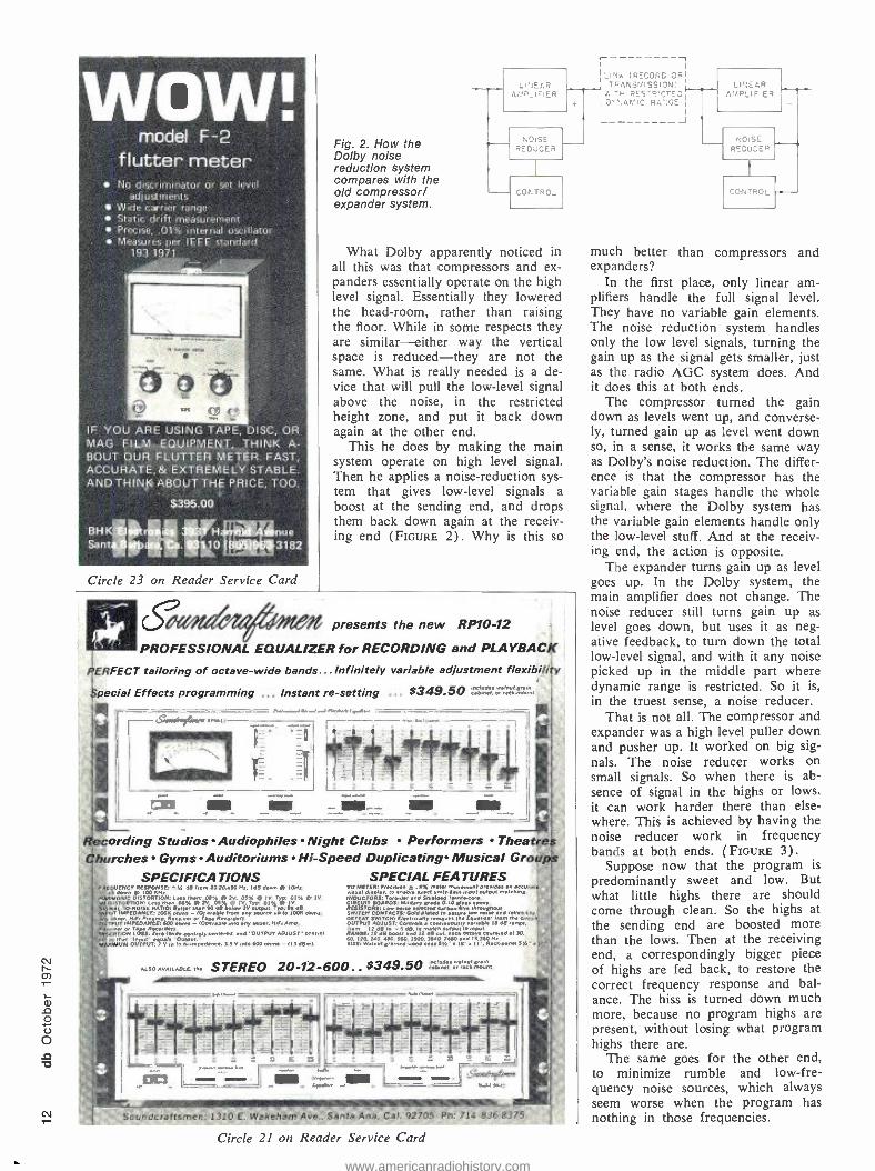
Fig. 2. How the Dolby noise reduction system compares with the old compressor/ expander system.
LINEAR AMP_IFIER
NOISE REDUCES
COt: TRO_
What Dolby apparently noticed in all this was that compressors and ex- panders essentially operate on the high level signal. Essentially they lowered the head -room, rather than raising the floor. While in some respects they are similar- either way the vertical space is reduced -they are not the same. What is really needed is a de- vice that will pull the low -level signal above the noise, in the restricted height zone, and put it back down again at the other end.
This he does by making the main system operate on high level signal. Then he applies a noise -reduction sys- tem that gives low -level signals a boost at the sending end, and drops them back down again at the receiv- ing end (FIGURE 2). Why is this so
It presents the new RP1O -12
PROFESSIONAL EQUALIZER for RECORDING and PLAYBACK
ERFECT tailoring of octave -wide bands...Infinitely variable adjustment flexibility
pedal Effects programming ... Instant re- setting .. . $349.50 ".bmele....emg,.-
,a.. I _-i il
Iéecording Studios Audiophiles Night Clubs Performers Theatres hurches Gyms Auditoriums Hi -Speed Duplicating Musical Groups
SPECIFICAT IONS OV CNC YRE5v0oN dB .e m O..0 Hs. InB down
. o@
e
1101.0.
oC n.
Nu nrCÚI9iORtON:Le Man: rvÓ%5%iiTv1% e@ b mIV
vTiAsN@iv9Á Ìv.t%R ÌJOrvI.OxOE[RTIÓ
Belt.. than 90d below ]v u.Ty'95dB. UTMrEOAaçE: loon ohms a0 .
e
Ib.wéÉ M nm. OÑ IÓSERÌero eie* centro. ceme.d. And bUTPVT A0/u5r..mN.e. l
M óúïór.:iv e n
OubOR.d.z.. 5 v oto soo.bm. - no dem).
ALSO AVAILABLE In.
SPECIAL FEATURES VV METER: neN4en ¢ .!% IRON. ,n..e.mnt d,wlde..n +sc..,.
Neel sófxa
t.entda mate,,..
RESIISTOFi Le.nmse satirtsá u.non;brFliuébeut SWITCH CONTAC,
h n°ÓÌaasausiEa
0Ms8s nlerc OUTPUT ADJUST: Ce ii uy 1Á I
1 8RAN ]E iÓ iC 99E]MÌe b o`i ..6 } s 6Ó M. Ö
+ Öei )Óni`i
9EE w. ut E .ed wed c.se 5% sad
l'. ed O J0.
RO.o.nNl 5%'+
STEREO 20 -12 -600.. $349.50 =.17.1:=7.,.
L Soundcraftsmen: 1310 E. Wakeham Aoe., Santa Ana, Cal. 92705 Ph: 714. 8368375
Circle 21 on Reader Service Card
I ,
I, INK (RECORD ORI TAANSNISSIONi
I
wTN RES'R!CTEDI I D":ANIC RA>:GE I
I I
l J
LINEAR I_
AIAPLIF'ER
NOISE REDUCER
}
co-. TROL
much better than compressors and expanders?
In the first place, only linear am- plifiers handle the full signal level. They have no variable gain elements. The noise reduction system handles only the low level signals, turning the gain up as the signal gets smaller, just as the radio AGC system does. And it does this at both ends.
The compressor turned the gain down as levels went up, and converse- ly, turned gain up as level went down so, in a sense, it works the same way as Dolby's noise reduction. The differ- ence is that the compressor has the variable gain stages handle the whole signal, where the Dolby system has the variable gain elements handle only the low -level stuff. And at the receiv- ing end, the action is opposite.
The expander turns gain up as level goes up. In the Dolby system, the main amplifier does not change. The noise reducer still turns gain up as level goes down, but uses it as neg- ative feedback, to turn down the total low -level signal, and with it any noise picked up in the middle part where dynamic range is restricted. So it is, in the truest sense, a noise reducer.
That is not all. The compressor and expander was a high level puller down and pusher up. It worked on big sig- nals. The noise reducer works on small signals. So when there is ab- sence of signal in the highs or lows, it can work harder there than else- where. This is achieved by having the noise reducer work in frequency bands at both ends. ( FIGURE 3) .
Suppose now that the program is
predominantly sweet and low. But what little highs there are should come through clean. So the highs at the sending end are boosted more than the lows. Then at the receiving end, a correspondingly bigger piece of highs are fed back, to restore the correct frequency response and bal- ance. The hiss is turned down much more, because no program highs are present, without losing what program highs there are.
The same goes for the other end, to minimize rumble and low -fre- quency noise sources, which always seem worse when the program has nothing in those frequencies.
www.americanradiohistory.com

BAND I
BAND 2 I -
BAND 3 I---.
BAND 4 F-
NOISE REDUCER
ELEMENTS
Fig. 3. The Dolby system can do what the compressor /expander could not - noise reduced by frequency, instead of waveform.
If the noise -reducing system errs, in the precision with which it cor- rects for what it did at the sending end, what happens? The high -level sound is unchanged, because that is
not where it works. It just over re- stores the dynamic range, and the accompanying noise (or under) as the case may be. Either way, it does not seriously affect program content, by introducing a spurious swelling or breathing effect of its own.
And from the theory and practice viewpoint, which is why we picked it to talk about, it handles the pro- gram audio more in the way we hear it, as a collection of frequencies, or tones, where the old compressor/ expander combination handled the signal as a composite whole -a wave- form of varying amplitude.
Copies of db on Microfilm
Copies of all issues of db -The Sound Engineering Magazine start- ing with the November 1967 issue are now available on 35 mm. micro- film. For further information or to place your order please write di- rectly to:
University Microfilm, Inc. 300 North Zeeb Road Ann Arbor, Michigan 48106 A subsidiary of Xerox
Corporation
In addition to Microfilm Copies available through University Micro- film. we have a limited number of regular back issues available. You may order these copies at $1.00 each from:
Circulation Department db -The Sound Engineering
Magazine 980 Old Country Road Plainview, New York 11803
don't ¿cIas! without a Cooper Time Cube * The only dual delay device available
UREI's unique Cooper Time Cube* gives you TWO completely independent audio delay lines, at less than one -third the cost of a single channel digital unit.
Cost per MS less than 1/3 that of a digital device Lowest distortion, even at low levels (less than .5%) Excellent signal- se - better than 70db Excellent frev..l nb ponse, bandwidth 30 Hz to 10 KHz
r+ The Model 920- 16:ytem provides/TWO electronically inde- pendent delays: One of 16MS and one of 14MS. They can be used separately, in Quad synthesis or for simultaneous "loud- ness enhancement" of two single channels. Or, the two delay lines may be cascaded for 30MS delay to an "echo chamber" or reverberation device. Model 920 -16 Time Cube is the only acoustical delay line system of professional :quality, and is designed specifically for record- ing studio applications and optical film recording.
See your dealer or write for complete specifications.
'Evolved from the }brig {nal design of Dr. Duane H. Cooper of The University of Illinois, in collaboration h T. Putnam of UREI.
a L 1R company
11922 Valerio Street, No. Hollywood, California 91605 (213) 764 -1500 Exclusive export agent: Gotham Export Corporation, New York
Circle 20 on Reader Service Card C.0
www.americanradiohistory.com
v T
John M. Woram
THE SYNC TRACK
This is being written on the eve (almost) of the 43rd Audio Engineer- ing Society convention. Since I've managed to get involved in the quad session, I've lately been reviewing the past year's activities in quad. Most of the various quad- oriented conferences and meetings have already been dis- cussed in these pages. But at least one interesting gathering has not - the Sixth Annual Audio Recording Seminar held at Brigham Young Uni- versity. This year the seminar was largely devoted to a look at quad sound.
Bert Whyte was the first speaker at the seminar. In a most enlightening lecture, he recalled some of the early attempts. It seems that the Shah of Persia had a three -channel Edison cyl- inder many years ago, but it didn't really catch on too well. Perhaps the ladies of the harem objected to the ungainly appearance of the three horns. Bert offered no explanation for the untimely demise of the device. Nor did he mention whether he him- self had a hand in getting the Shah started in multi -track. I expect he would disclaim all responsibility. How- ever, he [Bert, not the Shah] has been around for most of the other developments in the state of our art.
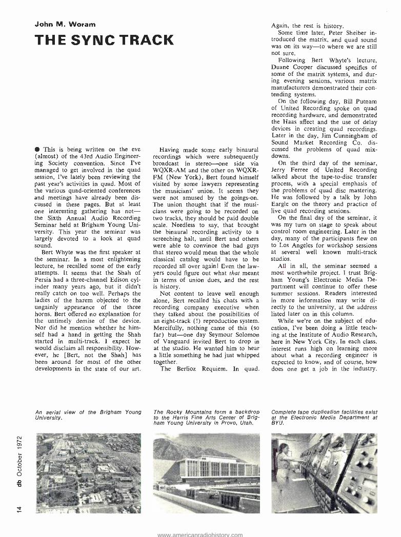
An aerial view of the Brigham Young University.
Having made some early binaural recordings which were subsequently broadcast in stereo -one side via WQXR -AM and the other on WQXR- FM (New York), Bert found himself visited by some lawyers representing the musicians' union. It seems they were not amused by the goings -on. The union thought that if the musi- cians were going to be recorded on two tracks, they should be paid double scale. Needless to say, that brought the binaural recording activity to a screeching halt, until Bert and others were able to convince the bad guys that stereo would mean that the whole classical catalog would have to be recorded all over again! Even the law- yers could figure out what that meant in terms of union dues, and the rest is history.
Not content to leave well enough alone, Bert recalled his chats with a recording company executive when they talked about the possibilities of an eight -track (!) reproduction system. Mercifully, nothing came of this (so far) but -one day Seymour Solomon of Vanguard invited Bert to drop in at the studio. He wanted him to hear a little something he had just whipped together.
The Berlioz Requiem. In quad.
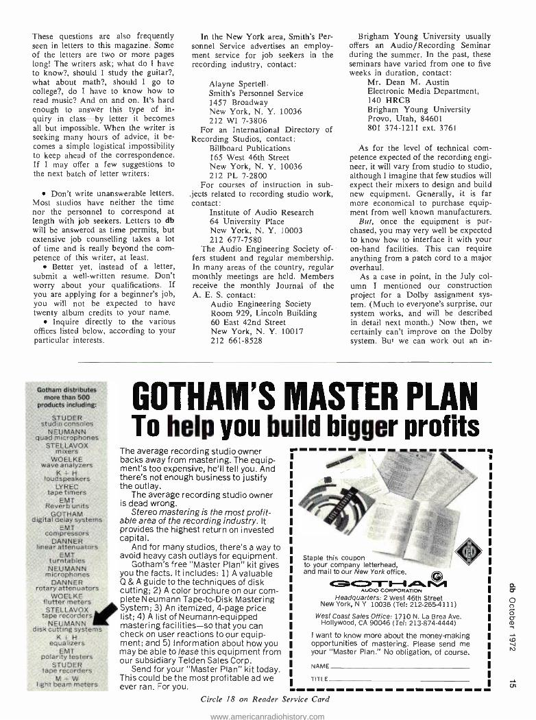
The Rocky Mountains form a backdrop to the Harris Fine Arts Center of Brig- ham Young University in Provo, Utah.
Again, the rest is history. Some time later, Peter Sheiber in-
troduced the matrix, and quad sound was on its way -to where we are still not sure.
Following Bert Whyte's lecture, Duane Cooper discussed specifics of some of the matrix systems, and dur- ing evening sessions, various matrix manufacturers demonstrated their con- tending systems.
On the following day, Bill Putnam of United Recording spoke on quad recording hardware, and demonstrated the Haas affect and the use of delay devices in creating quad recordings. Later in the day, Jim Cunningham of Sound Market Recording Co. dis- cussed the problems of quad mix - downs.
On the third day of the seminar, Jerry Ferree of United Recording talked about the tape -to -disc transfer process, with a special emphasis of the problems of quad disc mastering. He was followed by a talk by John Eargle on the theory and practice of live quad recording sessions.
On the final day of the seminar, it was my turn on stage to speak about control room engineering. Later in the day, many of the participants flew on to Los Angeles for workshop sessions at several well known multi -track studios.
All in all, the seminar seemed a most worthwhile project. I trust Brig- ham Young's Electronic Media De- partment will continue to offer these summer sessions. Readers interested in more information may write di- rectly to the university, at the address listed later on in this column.
While we're on the subject of edu- cation, I've been doing a little teach- ing at the Institute of Audio Research, here in New York City. In each class, interest runs high on learning more about what a recording engineer is expected to know, and of course, how does one get a job in the industry.
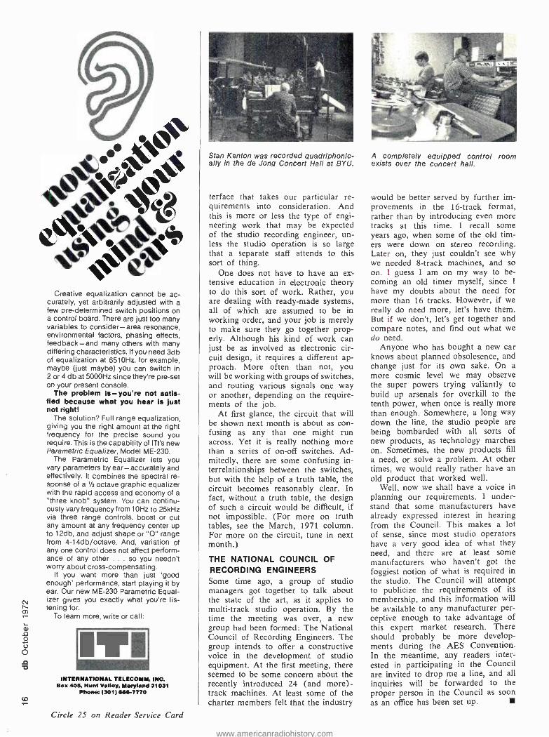
Complete tape duplication facilities exist at the Electronic Media Department at BY U.
www.americanradiohistory.com
These questions are also frequently seen in letters to this magazine. Some of the letters are two or more pages long! The writers ask; what do I have to know ?, should I study the guitar ?, what about math ?, should I go to college ?, do I have to know how to read music? And on and on. It's hard enough to answer this type of in- quiry in class -by letter it becomes all but impossible. When the writer is seeking many hours of advice, it be- comes a simple logistical impossibility to keep ahead of the correspondence. If I may offer a few suggestions to the next batch of letter writers:
Don't write unanswerable letters. Most studios have neither the time nor the personnel to correspond at length with job seekers. Letters to db will be answered as time permits, but extensive job counselling takes a lot of time and is really beyond the com- petence of this writer, at least.
Better yet, instead of a letter, submit a well -written resume. Don't worry about your qualifications. If you are applying for a beginner's job, you will not be expected to have twenty album credits to your name.
Inquire directly to the various offices listed below, according to your particular interests.
In the New York area, Smith's Per- sonnel Service advertises an employ- ment service for job seekers in the recording industry, contact:
Alayne Spertell. Smith's Personnel Service 1457 Broadway New York, N. Y. 10036 212 WI 7 -3806
For an International Directory of Recording Studios, contact:
Billboard Publications 165 West 46th Street New York, N. Y. 10036 212 PL 7 -2800
For courses of instruction in sub- jects related to recording studio work, contact:
Institute of Audio Research 64 University Place New York, N. Y. 10003 212 677 -7580
The Audio Engineering Society of- fers student and regular membership. In many areas of the country, regular monthly meetings are held. Members receive the monthly Journal of the A. E. S. contact:
Audio Engineering Society Room 929, Lincoln Building 60 East 42nd Street New York, N. Y. 10017 212 661 -8528
Brigham Young University usually offers an Audio /Recording Seminar during the summer. In the past, these seminars have varied from one to five weeks in duration, contact:
Mr. Dean M. Austin Electronic Media Department, 140 HRCB Brigham Young University Provo, Utah, 84601 801 374 -1211 ext. 3761
As for the level of technical com- petence expected of the recording engi- neer, it will vary from studio to studio, although I imagine that few studios will expect their mixers to design and build new equipment. Generally, it is far more economical to purchase equip- ment from well known manufacturers.
But, once the equipment is pur- chased, you may very well be expected to know how to interface it with your on -hand facilities. This can require anything from a patch cord to a major overhaul.
As a case in point, in the July col- umn I mentioned our construction project for a Dolby assignment sys- tem. (Much to everyone's surprise, our system works, and will be described in detail next month.) Now then, we certainly can't improve on the Dolby system. But we can work out an in-
Gotham distributes more than 500
products including:
STUDER studio consoles
NEUMANN quad microphones
STELLAVOX mixers
WOELKE wave analyzers
K + H loudspeakers
LYREC tape timers
EMT Reverb units
GOTHAM digital delay systems
EMT compressors
DANNER linear attenuators
EMT turntables NEUMANN
microphones DANNER
rotary attenuators WOELKE
flutter meters STELLAVOX
tape recorders NEUMANN
disk cutting systems K + H
equalizers EMT
polarity testers STUDER
tape recorders M
light beam meters
GOTHAM'S MASTER PLAN To help you build bigger profits
The average recording studio owner backs away from mastering. The equip- ment's too expensive, he'll tell you. And there's not enough business to justify the outlay.
The average recording studio owner is dead wrong.
Stereo mastering is the most profit- able area of the recording industry. It provides the highest return on invested capital.
And for many studios, there's a way to avoid heavy cash outlays for equipment.
Gotham's free "Master Plan" kit gives you the facts. It includes: 1) A valuable Q & A guide to the techniques of disk cutting; 2) A color brochure on our com- plete Neumann Tape -to -Disk Mastering System; 3) An itemized, 4 -page price list; 4) A list of Neumann -equipped mastering facilities -so that you can check on user reactions to our equip- ment; and 5) Information about how you may be able to lease this equipment from our subsidiary Telden Sales Corp.
Send for your "Master Plan" kit today. This could be the most profitable ad we ever ran. For you.
Staple this coupon to your company letterhead, and mail to our New York office.
GO_1- t AUDIO CORPORATION
Headquarters: 2 West 46th Street New York, N Y 10036 (Tel: 212 -265 -4111)
West Coast Sales Office: 1710 N. La Brea Ave. Hollywood, CA 90046 (Tel: 213- 874 -4444)
I want to know more about the money- making opportunities of mastering. Please send me your "Master Plan." No obligation, of course.
NAME
TITLE
Circle 18 on Reader Service Card
cn
www.americanradiohistory.com
4e" '44 o45
e4ko Creative equalization cannot be ac-
curately, yet arbitrarily adjusted with a few pre- determined switch positions on a control board. There are just too many variables to consider -area resonance, environmental factors, phasing effects, feedback -and many others with many differing characteristics. If you need 3db of equalization at 6510Hz, for example, maybe (just maybe) you can switch in 2 or 4 db at 5000Hz since they're pre -set on your present console.
The problem is- you're not satis- fied because what you hear is just not right!
The solution? Full range equalization, giving you the right amount at the right frequency for the precise sound you require. This is the capability of ITI's new Parametric Equalizer, Model ME -230.
The Parametric Equalizer lets you vary parameters by ear - accurately and effectively. It combines the spectral re- sponse of a 1/3 octave graphic equalizer with the rapid access and economy of a "three knob" system. You can continu- ously vary frequency from 10Hz to 25kHz via three range controls. boost or cut any amount at any frequency center up to 12db, and adjust shape or "Q" range from 4 -14db /octave. And, variation of any one control does not affect perform- ance of any other ... so you needn't worry about cross -compensating.
If you want more than just 'good enough' performance, start playing it by ear. Our new ME -230 Parametric Equal- izer gives you exactly what you're lis- tening for.
To learn more, write or call:
INTERNATIONAL TELECOMM, INC. Box 405, Hunt Valley, Maryland 21031
Phone: (001) 656 -7770
Circle 25 on Reader Service Card
Stan Kenton was recorded quadriphonic- ally in the de Jong Concert Hall at BY U.
[efface that takes our particular re- quirements into consideration. And this is more or less the type of engi- neering work that may be expected of the studio recording engineer, un- less the studio operation is so large that a separate staff attends to this sort of thing.
One does not have to have an ex- tensive education in electronic theory to do this sort of work. Rather, you are dealing with ready -made systems, all of which are assumed to be in working order, and your job is merely to make sure they go together prop- erly. Although his kind of work can just be as involved as electronic cir- cuit design, it requires a different ap- proach. More often than not, you will be working with groups of switches, and routing various signals one way or another, depending on the require- ments of the job.
At first glance, the circuit that will be shown next month is about as con- fusing as any that one might run across. Yet it is really nothing more than a series of on -off switches. Ad- mitedly, there are some confusing in- terrelationships between the switches, but with the help of a truth table, the circuit becomes reasonably clear. In fact, without a truth table, the design of such a circuit would be difficult, if not impossible. (For more on truth tables, see the March, 1971 column. For more on the circuit, tune in next month.)
THE NATIONAL COUNCIL OF RECORDING ENGINEERS Some time ago, a group of studio managers got together to talk about the state of the art, as it applies to multi -track studio operation. By the time the meeting was over, a new group had been formed: The National Council of Recording Engineers. The group intends to offer a constructive voice in the development of studio equipment. At the first meeting, there seemed to be some concern about the recently introduced 24 (and more) - track machines. At least some of the charter members felt that the industry
A completely equipped control room exists over the concert hall.
would be better served by further im- provements in the 16 -track format, rather than by introducing even more tracks at this time. 1 recall some years ago, when some of the old tim- ers were down on stereo recording. Later on, they just couldn't see why we needed 8 -track machines, and so on. I guess I am on my way to be- coming an old timer myself, since I
have my doubts about the need for more than 16 tracks. However, if we really do need more, let's have them. But if we don't, let's get together and compare notes, and find out what we do need.
Anyone who has bought a new car knows about planned obsolesence, and change just for its own sake. On a
more cosmic level we may observe the super powers trying valiantly to build up arsenals for overkill to the tenth power, when once is really more than enough. Somewhere, a long way down the line, the studio people are being bombarded with all sorts of new products, as technology marches on. Sometimes, the new products fill a need, or solve a problem. At other times, we would really rather have an old product that worked well.
Well, now we shall have a voice in planning our requirements. I under- stand that some manufacturers have already expressed interest in hearing from the Council. This makes a lot of sense, since most studio operators have a very good idea of what they need, and there are at least some manufacturers who haven't got the foggiest notion of what is required in the studio. The Council will attempt to publicize the requirements of its membership, and this information will be available to any manufacturer per- ceptive enough to take advantage of this expert market research. There should probably be more develop- ments during the AES Convention. In the meantime, any readers inter- ested in participating in the Council are invited to drop me a line, and all inquiries will be forwarded to the proper person in the Council as soon as an office has been set up.
www.americanradiohistory.com
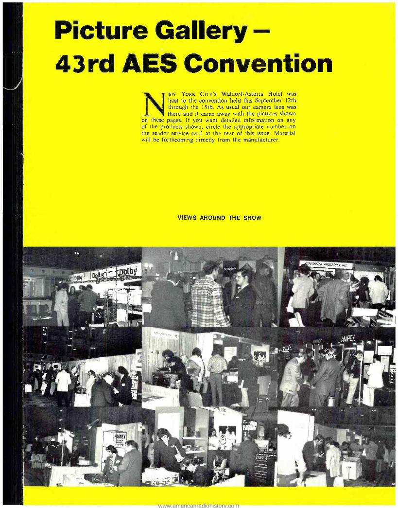
Picture Gallery 43rd AES Convention
NEW YORK CITY'S Waldorf- Astoria Hotel was host to the convention held this September 12th through the 15th. As usual our camera lens was there and it came away with the pictures shown
on these pages. If you want detailed information on any of the products shown, circle the appropriate number on the reader service card at the rear of this issue. Material will be forthcoming directly from the manufacturer.
VIEWS AROUND THE SHOW
"
www.americanradiohistory.com

CO
Model A80 is the designation for this newest Studer, designed for mas- tering. Circle 51 on Reader Service Card.
The Scully Syncmaster puts the complete control of the machine on your console. Circle 75 on Reader Service Card. , :`;; ,
The Ampex CD -200 duplicating system is for high speed copies made in the cassette. Circle 89 on Reader Service Card.
The newest of the multitrack ma- chines from 3M -the series 79. Circle 54 on Reader Service Card.
This recorder by Tascam uses f- inch tape for low -cost 8 -track record- ing. Circle 87 on Reader Service Card.
Eventide Clockworks now has a
digital delay line at reduced price. Circle 71 on Reader Service Card.
Xedit is now prepared to deliver their specialized sixteen -track recorder. Circle 67 on Reader Service Card.
Electrosound produces duplicators for cassette that can run at 240 in/ sec. Circle 72 on Reader Service Card.
This URL recorder can record quad on both 1/4 -inch and 1 -inch tapes. Circle 74 on Reader Service Card.
Infonics' Systems 200 offer a mod- ular system approach to cassette du- plication. Circle 90 on Reader Service Card.
Four channels of noise reduction are included in the dbx 157 system. Circle 59 on Reader Service Card.
Completely revised encoder and de- coder modules are available from Sansui. Circle 88 on Reader Service Card.
www.americanradiohistory.com

Lower per unit cost is featured in the Dolby up -to -24 channel M24 A- type system. Circle 61 on Reader Service Card.
The E -V Interface A uses a drone cone to get deep bass out of a small box. Circle 81 on Reader Service Card.
Stanton Magnetics full line of elec- trostatic and dynamic headphones. Circle 86 on Reader Service Card.
An unusual amount of equalization is provided by the ITI parametric unit. Circle 66 on Reader Service Card.
This AKG microphone can reach into areas in which conventional mics can't get. Circle 82 on Reader Service Card.
Under the Revox banner, Beyer offers a wide range of ribbon and dynamic microphones. Circle 58 on Reader Service Card.
Shure's latest microphone, the SM54 has improved pop protection built in. Circle 63 on Reader Service Card.
Crown offers the maintenance en- gineer this sophisticated IM analyzer. Circle 60 on Reader Service Card.
n fancy free.That's us.
Beautiful schooner. Exciting Ii'I West Indies Isles. And you.
If you're congenial and would like to sail with a
small, intimate group, we're for you and you're for us. Now forming to sail.
Your share from $245. 10 great days. Hurry. Write today for information.
OWindjammer Cruises.
Name_ Address -
City Stace Z'p
Phone
P.O. Box 120, Dept. 9700. Miami Beach, Florida 33139
J co
www.americanradiohistory.com

0 N
Pretty Barbara Brosious of Audio - techniques shows the smallest (Allen & Heath) mixer. Circle 55 on Reader Service Card.
The UREI Sonipulse is designed as an audio analyzer of room conditions. Circle 65 on Reader Service Card.
Q
Zv~i O W
:ale -MOM
a { K x
i O O° ó N Ú > J
OY 03 6 2 ON ON 1- H
fio Qs O\ Y w t--K - >< áV o ctt - 2 vs v in
aa°Y-,- J Circle 26 on Reader Service Card
Allison and Automated Processes have teamed up to produce automated mixing systems. Circle 76 on Reader Service Card.
Olive offers a variety of consoles with built in automation systems. Circle 64 on Reader Service Card.
This is Auditronic's new console -dubbed the Son of 36 Grand. Cir- cle 83 on Reader Service Card.
MCI, known for multi -track re- corders also offers this JH -416 mixing console. Circle 84 on Reader Service Card.
The sign on this new Gately con- sole speaks for itself -it sold at the show. Circle 68 on Reader Service Card.
Not only large consoles; small con- soles too are made by Neve. Circle 53 on Reader Service Card.
Bill Dilley's hand is seen holding Spectra -Sonic's mini quad pot. Circle 70 on Reader Service Card.
Fairchild Sound Integra II com- ponents permit you to assemble a custom console. Circle 57 on Reader Service Card.
www.americanradiohistory.com

EEC LED RO3
E F G A B C D
RALPH E. HORNBERGER
Build a Digital Readout Electronic Stopwatch
ALL BROADCAST AND RECORDING studios Use Some method of measuring elapsed time. The usual method is either a mechanical stop -watch or an electric clock. Both of these methods have their
shortcomings. The mechanical stopwatch has a small scale which is easy to misread, is difficult to interface with tape decks and cartridge machines, and is easily broken. The electric clock is easier to read and interface with the studio equipment, but starts slowly and drifts when stopped. There are clocks and watches that get around these problems, but their major drawback is their high cost.
The electronic stopwatch presented here is one answer to these problems. It uses one -quarter inch high light - emitting diode displays, which because of their bright red color, arc highly visible at a distance. The rest of the stopwatch with its [C's should be trouble free, and the led's have a projected life of one hundred years. It is also very easy to connect it to a tape deck or cartridge ma-
R7-R41 I 50t1 (35) -
chine or to remote control it. Since the stopwatch uses the 60 Hz power line for its time base its accuracy (at least in most parts of the country) will be on the order of 0.05 per cent.
The electronic stopwatch is inexpensive to construct, with the cost running between forty and fifty -five dollars depending on the size of the display and local parts cost. This is less than the cost of most good mechanical watches. Finally, it is easy to build and requires no special tools or test equipment.
CIRCUIT OPERATION
FIGURE 1 shows the schematic of the stopwatch. It is con- structed using two printed- circuit boards: the larger board holds the power supply, control, counting, and decoding circuits; the smaller board holds the led readouts. The dotted line on the schematic indicates the two different boards.
Referring to the schematic: Rl, R2, and Cl filter the
EMI LED RO5
EFGABCD
+5
10 MIN
Mir LED R04
EFGABCO I MIN
Ii1ii145 9 5111 1- ° +5 Ji1IiiI'
EFGABCOVcc E GABCDVcc 4 5 RBI 7447 RBO 4 5 RBI 7447 RBD
BGND ICI BGND ICIO B
Di Ci Bi AI = 01 Ci Bi AI
6
5 9'1 +5* 5 I : +50 5 8 9
E FGA BCDVE RBI 7447 RBO
GND IC12 Di Cl Bi Ai
14
LED LED 10 SEC R02 I SEC R01 I /10 SEC
+5
VEO Go Bo Ao 7492 BD'
GNO 1 C 7 Ai Ro Ro
4
6 NOMA 8
-6 IN 4001 -- la-
06
ii 6.3vAC I 2A
Vcc Do Co Bn Ao 7490 BO'
GND IC6 Ai RG RG Ro Ro
7
+IO
4 0
IN 4001 05
7
r6
4
EF GABCD EF GAB CDOP6
tlluiiI5 9111 E FO A BCD Vcc
4 5 RBI 7447 B GND 1 C8
Di Ci Bi A
+5 6111 +5° ' n :
E G ABC OVCc RBI 7447 RB
GND 109 Di Ci Bi Ai
Vct Do Co Bo Ao 7490 BB'
GND 1 C4 Ai RG RG Ro Ro
7 2
+10
w 3
14
2' Y
R43 470
R42 10 1W
8
+5 ! JUMPER X TO DISPLAY ODD 5:H'S (1,3,5,7,9) p +5
2
vcc Do Co Bo Ao 7490 BB'
10GND IC3 Ai RG RG Ro Ro 017 2013
+10
START
4.7K +5
4.7K 0 o o S2 STOP
I N4001 (4)
7
B TO DISPLAY BOARD
SEE TEXT +5
4 2W4 C2 -1-1000/35
RI 56
CI 10/15
A
R2 180
7 SEGMENT DISPLAY FORMAT
F/ /B
E/ /C D
4
4
+5 y^- TO RE SET °15 r- 0 3 IOHER IC'Svcc 7492 Ai iA
NOT USED) _1oRODRAI BDi
co
I RESET 6t7
-J ' +6
+50-o o i S3 t 47
15I/2 w
Figure 1. The five digit, one hour electronic stopwatch. All resistors are U4 watt unless otherwise noted.
JUMPER Y TO DISPLAY EVEN STN'S (0,2,4,6,8)
JUMPER Z TO
DISPLAY IOTH'S'
www.americanradiohistory.com

Ñ radio station WFIL in Philadelphia.
Figure 2. Exact size toil layout.
a g
iiPiiiii iPiilil III
888881. 8888888 8888888. 8868858: 8888888
o el or Al l
L f eo Jo ic;
cs,
IC STOPWATCH reh
60 Hz from TI and feed the conditioned a.c. to the A input of IC2. 1C2 is a divide -by- twelve counter which in this circuit is wired to divide by six. The A output of IC2 is connected to one input of gate 4 of ICI which has four dual input Nand gates. The output of gate 4 is fed back to the BD input of IC2. Gate 4, as will be described later, is used to turn the clock on and off.
The C output of IC2 supplies 10 Hz to the A input of 1C3, a divide by ten counter. This counter drives the tenths -of- seconds display. IC3 also supplies one pulse per second to IC4, another divide -by -ten counter. IC4 drives the one -second display. 105 is a divide -by- twelve counter wired to divide by six. It is supplied with a pulse every ten seconds from IC4 and drives the tens -of- seconds dis- play. It also drives IC6 with a pulse every minute. IC6 drives the minutes display. IC7, a divide -by- twelve wired to divide by six, is driven by IC6 with a pulse every ten minutes and drives the tens -of- minutes display.
1C8 through IC12 are decoding circuits which take the 1 -2 -4 -8 binary -coded output of the counting circuits and
Ralph E. Hornberger is assistant engineering supervisor at
convert them into the logic and current capability neces- sery to drive the seven segment displays. The decoding i.c.'s are also wired to perform most significant zero blanking. This blanking will cause the left hand zeros to extinguish. If the clock is reset the whole display will extinguish.
The numerals on the displays are of the seven segment type, each segment made up of individual light- emitting diodes. The segments are wired internally in a common anode configuration. The decoder i.c.'s supply seven sep- arate open collectors, each of which is wired to the appro- priate segment cathode through a current -limiting resistor. The current -limiting resistor may be any value between 47 and 200 ohms. One hundred -fifty ohms was chosen to keep the segment current down to about 10 mA. Low- ering the resistance to 47 ohms will double the display brightness but will also double the segment current and requires greater power -supply current capability. The dis- play brightness at 10 mA is 500 foot -Lamberts and is adequate for most viewing conditions.
Start, and stop control of the stopwatch is done through ICI. Gates 1 and 2 are wired as an RS flip -flop. Both flip -flop inputs are held in a high state by R4 and R5, but one of the outputs will be low and one high due to the cross coupling between them. When the start button, Si, is pressed it causes gate l's output to go high and gate 2's output to go low. The opposite will happen when the stop button, S2, is pressed.
www.americanradiohistory.com
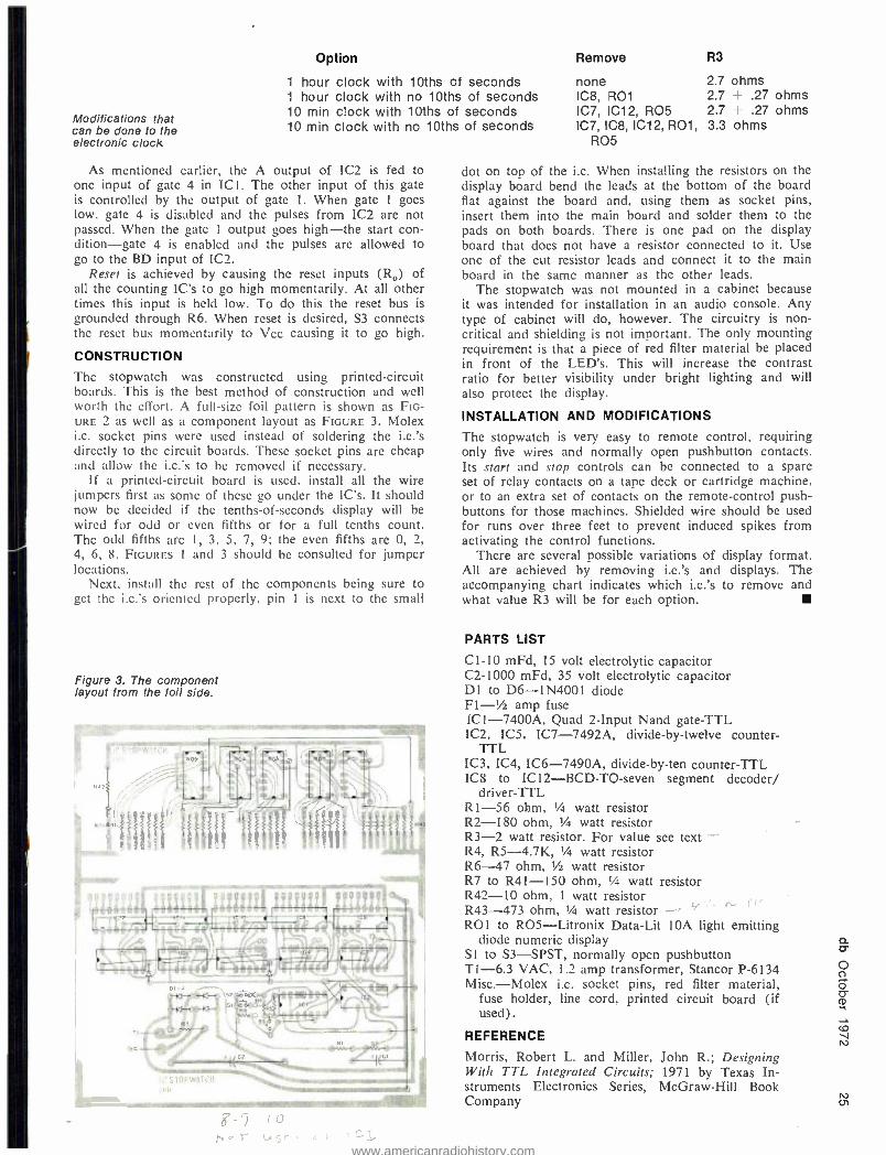
Modifications that can be done to the electronic clock
O p t i o n
1 hour clock with 10ths of seconds 1 hour clock with no 10ths of seconds 10 min clock with 10ths of seconds 10 min clock with no 10ths of seconds
Remove
none IC8, RO1 IC7, IC12, R05 IC7, IC8, IC12, R01,
R05
R3
2.7 ohms 2.7 + .27 ohms 2.7 + .27 ohms 3.3 ohms
As mentioned earlier, the A output of 1C2 is fed to one input of gate 4 in ICI. The other input of this gate is controlled by the output of gate 1. When gate 1 goes low, gate 4 is disabled and the pulses from IC2 are not passed. When the gate 1 output goes high -the start con- dition -gate 4 is enabled and the pulses are allowed to go to the BD input of IC2.
Reset is achieved by causing the reset inputs (R0) of all the counting IC's to go high momentarily. At all other times this input is held low. To do this the reset bus is grounded through R6. When reset is desired, S3 connects the reset hus momentarily to Vcc causing it to go high.
CONSTRUCTION
The stopwatch was constructed using printed- circuit boards. This is the best method of construction and well worth the effort. A full -size foil pattern is shown as FIG - URE 2 as well as a component layout as FIGURE 3. Molex i.c. socket pins were used instead of soldering the i.c.'s directly to the circuit boards. These socket pins are cheap and allow the i.c.'s to be removed if necessary.
If a printed- circuit board is used, install all the wire jumpers first as some of these go under the IC's. It should now be decided if the tenths -of- seconds display will be wired for odd or even fifths or for a full tenths count. The odd fifths are I, 3, 5, 7, 9; the even fifths are 0, 2, 4, 6, 8. FIGURES I and 3 should be consulted for jumper locations.
Next, install the rest of the components being sure to get the i.c.'s oriented properly, pin I is next to the small
Figure 3. The component layout from the foil side.
r-
r- $¡1M 1;;f
;?Pt944 r.
--r--r--
-+c-- -+-- b --
so >.v:x, .:. MMINEK.1.01;
F- o n r - - : -
dot on top of the i.c. When installing the resistors on the display board bend the leads at the bottom of the board flat against the board and, using them as socket pins, insert them into the main board and solder them to the pads on both boards. There is one pad on the display board that does not have a resistor connected to it. Use one of the cut resistor leads and connect it to the main board in the same manner as the other leads.
The stopwatch was not mounted in a cabinet because it was intended for installation in an audio console. Any type of cabinet will do, however. The circuitry is non- critical and shielding is not important. The only mounting requirement is that a piece of red filter material be placed in front of the LED's. This will increase the contrast ratio for better visibility under bright lighting and will also protect the display.
INSTALLATION AND MODIFICATIONS
The stopwatch is very easy to remote control, requiring only five wires and normally open pushbutton contacts. Its start and stop controls can be connected to a spare set of relay contacts on a tape deck or cartridge machine, or to an extra set of contacts on the remote -control push- buttons for those machines. Shielded wire should be used for runs over three feet to prevent induced spikes from activating the control functions.
There are several possible variations of display format. All are achieved by removing i.c.'s and displays. The accompanying chart indicates which i.c.'s to remove and what value R3 will be for each option.
PARTS LIST
C1 -10 mFd, 15 volt electrolytic capacitor C2 -1000 mFd, 35 volt electrolytic capacitor DI to D6- 1N4001 diode F1 -'h amp fuse ICI- 7400A, Quad 2 -Input Nand gate -TTL IC2, IC5, IC7- 7492A, divide -by- twelve counter -
TTL IC3, IC4, 106- 7490A, divide -by -ten counter -TTL IC8 to ICI2- BCD -TO -seven segment decoder/
driver -TTL RI -56 ohm, Vs watt resistor R2 -180 ohm, '/4 watt resistor R3 -2 watt resistor. For value see text R4, R5 -4.7K, 1/4 watt resistor R6-47 ohm, '/z watt resistor R7 to R41 -150 ohm, 1/4 watt resistor R42 -10 ohm, 1 watt resistor R43 -473 ohm, '/4 watt resistor RO1 to R05- Litronix Data -Lit l0A light emitting
diode numeric display SI to S3 -SPST, normally open pushbutton T1 -6.3 VAC, 1.2 amp transformer, Stancor P -6134 Misc. -Molex i.c. socket pins, red filter material,
fuse holder, line cord, printed circuit board (if used).
REFERENCE
Morris, Robert L. and Miller, John R.; Designing With TTL Integrated Circuits; 1971 by Texas In- struments Electronics Series, McGraw -Hill Book Company
www.americanradiohistory.com
Automated AN OPEN LETTER TO STUDIOS
CONSIDERING AUTOMATION is NOW! It would seem that the audio industry is again taking a major step forward as it has done many times in the past. The step is into automation of the mixdown process. We, at Automated Processes and Allison Research, take cog- nizance of this and have jointly endeavored to create equipment and systems which are capable of making the step successful. In doing so, we feel a strong obligation to the industry both in the design of our hardware and in the philosophy of its use. What we have developed is the product of five years of research and planning, both in the laboratory and in the mixdown room.
In general, we feel that functional automation, whether for music, film or commercials, requires that the mixdown console or separate mixdown consolette self - program all relevant control functions in real time. In other words, the equipment must be capable of normal manual operation, but with the additional capacity to remember what was done, when it was done, and how it was done. It must then be able to precisely re- create the original mix any number of times without degradation while individual controls are readjusted to alter or im- prove any portion of the recording. Since we are dealing with a new technology, there are new terms and new considerations in choosing the equipment. We believe that these considerations must be made clear to the industry if the technology is to be successfully used.
Obviously, the first consideration is that the system work reliably, not only in theory, but in production form. If you were in attendance at the September 1972 AES Convention in New York City, you had the opportunity to witness a production package Allison /Automated system perform under the most demanding conditions. We es- timate that between 300 and 400 passes of the same 16 track master tape were put through the consolette with flawless results. We weren't concerned about putting on such a demonstration, because we had confidence that the Programmer would perform even after the tape was worn.
The second consideration is that the system you buy today must be readily expandable to fit tomorrow's needs. It is easy to claim that a method of programming can be expanded to provide 22 kilofunctions of automation should the need arise. Fine, perhaps the method can, but what about the piece of hardware you purchased? How much expansion can it provide before you run out of room, or power supply, or counting capability? And most important, can it be expanded without making ob- solete the data code you laid down in mixing today's tape? Can it provide expansion while maintaining suit- able updating rates?
We call our programmer "Model 256E /D ", because it is basically a 256 function device. It contains a 256 function card frame, 256 function power supplies, physi-
cal space, connectors, card guides, etc. You may buy it as a 16 function programmer at a 16 function price if you like, but you've still got yourself a 256 function CAPA- BILITY device.
How do you expand it? Simply add a Model 16E and Model 16D plug -in card for each additional 16 functions. That's all!
The importance of expansion will become apparent when you consider the following utilization format which is based on present or future 24 track capability.
Function 1 -24, individual channel gain Function 25 -48, individual channel echo send Function 49 -72, individual channel stereo panning
(left /right) Function 73 -96, individual channel quad panning
(front /rear) Function 97 -192, individual channel equalization
(four functions per channel) Function 193 -216, master levels, echo returns, etc. Function 217 -256, future functions Another consideration is updating speed. We believe
that updating must be fast enough to faithfully follow the control manipulations of the mixing engineer, yet not so fast as to respond to spurious noise.
When a channel is placed in the WRITE or UPDATE mode, only that channel's control data is changed, while all other data is re- recorded intact. However, to avoid the possibility of error due to signal degradation after multiple passes, all data is completely regenerated each time. This assures that what you hear is what you have stored on the tape.
What about standardization? If you program only fader levels on a tape in Studio A today, what happens a year from now when you attempt to play that tape in Studio B where faders, echo, panning and EQ have all been automated? With the Allison /Automated system, Studio B's decoder knows what Studio A's encoder did, and it performs accordingly and accurately. It permits you to keep the fader level information you programmed a year ago while you now program echo, panning, and EQ if you desire. You can even take the tape back to Studio A and expect the fader level information to still be valid and accurate. In short, all Allison /Automated sys- tems are compatible. This is no accident. We engineered them that way!
There are a lot of other considerations in automation, ranging from performance of the voltage control ampli- fiers, voltage control panners, etc., through human engineering and interface aspects, to overall system concepts. We have them covered, and are prepared to discuss any aspects of automation with you. We invite and encourage questions regarding specifications of the components in our system.
Sincerely,
ALLISON RESEARCH, INC.
AUTOMATED PROCESSES, INC.
www.americanradiohistory.com

MODEL 256 PROGRAMMING UNIT At the heart of the system is the Allison /Automated Pro- grammer, designed to avoid obsolescence by being capable of encoding up to 256 channels for recording on any conventional tape recorder. The Programmer con- tains independent Encoder and Decoder units, each of which employs state of the art analog and digital circuitry. This approach achieves the infinite resolution (stepless) control associated with analog systems while maintaining the error detection capability of digital circuitry.
The Model 256E Encoder consists of a 51/4" x 19" card frame, and is supplied with the Master Encoder module, one Model 16E switching card for 16 functions, and the required power supply modules.
The Model 256D Decoder, a separately packaged card frame with the same dimensions as the Encoder, contains the Master Decoder module, one Model 16D switching card for 16 functions, and the required power supply modules.
Both units can be expanded at any time in multiples of 16 functions by simply plugging in additional 16E and 16D switching cards. The expanded system will continue to decode tapes made prior to expansion. No other adjust- ment is necessary on either the programmer or the tape machine. In fact all tapes and programmers are inter- changeable without adjustment so that tapes made in one studio may be played in any other studio having similar equipment. MODEL 256 PROGRAMMER SPECIFICATIONS NUMBER OF FUNCTIONS: 16 to 256 expandable in
groups of 16 by means of plug -in circuit cards. UPDATING RATE: 800 Micro sec /function. ACCURACY: ± .2 dB, 0 to - 40
±2 dB, Oto -60 +0- inf @ - 80
BANDWIDTH REQUIRED: 5 kHz (35 dB S /N) RECORDING LEVEL: - 20 to -5 (actual level or level
variations have no effect). DROP -OUT AND SPLICE PROTECTION: Any occurrence
of sufficient magnitude to cause decoding error causes device to hold prior information until error signal is removed (Average of 30 sec.).
J COMPATABILITY (System to System): Compatability
within +1 dB. Decoder automatically senses the number of encoded functions present and adjusts its cycling rate accordingly. Decoder also displays (via LED array) the number of encoded functions as an aid to determining the degree of automation on tape of unknown origin.
PACKAGING: Decoder and encoder separately packaged for remote control applications. Decoder: 51/4" x 19" rack panel. Encoder: 51/4" x 19" rack panel. Both units: 10" deep. Self powered.
MODEL 940 AUTOMATED FADER The Automated Fader is a self- contained channel
level control module capable of either manually or auto- matically setting audio levels. It contains all the elec- tronics and front panel controls necessary to record, play back, and update channel fader settings. In addition, it may be used as an automated master fader, or may be externally controlled for gate or mute functions. An Auto/ Manual switch is provided, which allows the module to operate as a normal audio fader, bypassing the automa- tion electronics entirely. The module incorporates a con- ductive plastic slide attenuator of the same quality and reliability that has made our Model 440 and 475 faders so popular.
The Model 940 Automated Fader fits in the space normally occupied by a conventional fader so that no additional console panel area is required in retro -fit applications.
Electrical performance characteristics are compat- ible with the Model 256 Programmer. Power requirements are as follows: ±15V @ 50mA, +5V @ 10mA, and lamp power of 5 to 6V @ 30mA.
Mounting Dimensions are: 7" high x 11/2" wide x 33/4" deep over mating connector.
You can automate your studio NOW with the Model 256 Programmer and the Model 940 Fader Modules, or with a pre -wired, ready -to -use 16 or 24 channel mixdown automation consolette ... and there's more to come!
We'll describe the Model 950 panning module and Model 960 echo module in our next automation adver- tisement.
AUTOMATED PROCESSES, INC. 80 MARCUS DRIVE, MELVILLE, NEWYORK 11746.516- 694 -9212
Circle 27 on Reader Service Card
ALLISON RESEARCH, INC.
2817 ERICA PL. P06ox40288
NASHVILLE, TENN. 37204
Dial 1615) 'ALLISON Or 16151 385.1760 N v
www.americanradiohistory.com
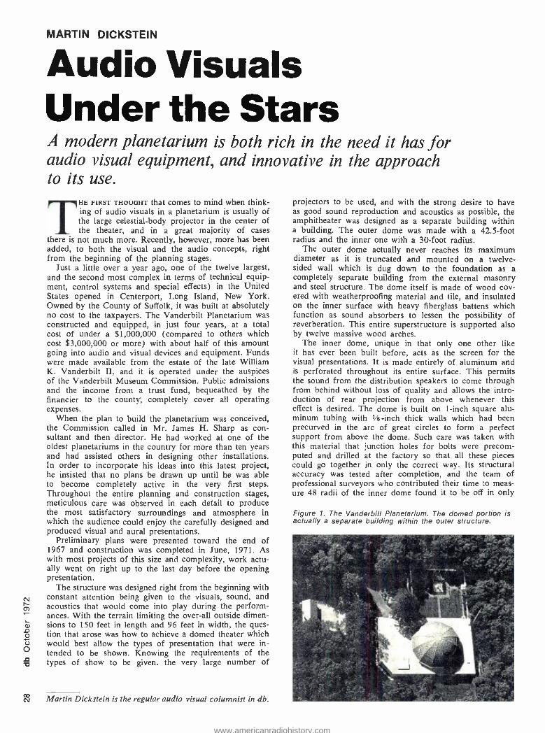
MARTIN DICKSTEIN
Audio Visuals Under the Stars A modern planetarium is both rich in the need it has for audio visual equipment, and innovative in the approach to its use.
THE FIRST THOUGHT that comes to mind when think- ing of audio visuals in a planetarium is usually of the large celestial -body projector in the center of the theater, and in a great majority of cases
there is not much more. Recently, however, more has been added, to both the visual and the audio concepts, right from the beginning of the planning stages.
Just a little over a year ago, one of the twelve largest, and the second most complex in terms of technical equip- ment, control systems and special effects) in the United States opened in Centerport, Long Island, New York. Owned by the County of Suffolk, it was built at absolutely no cost to the taxpayers. The Vanderbilt Planetarium was constructed and equipped, in just four years, at a total cost of under a $1,000,000 (compared to others which cost $3,000,000 or more) with about half of this amount going into audio and visual devices and equipment. Funds were made available from the estate of the late William K. Vanderbilt II, and it is operated under the auspices of the Vanderbilt Museum Commission. Public admissions and the income from a trust fund, bequeathed by the financier to the county, completely cover all operating expenses.
When the plan to build the planetarium was conceived, the Commission called in Mr. James H. Sharp as con- sultant and then director. He had worked at one of the oldest planetariums in the country for more than ten years and had assisted others in designing other installations. In order to incorporate his ideas into this latest project, he insisted that no plans be drawn up until he was able to become completely active in the very first steps. Throughout the entire planning and construction stages, meticulous care was observed in each detail to produce the most satisfactory surroundings and atmosphere in which the audience could enjoy the carefully designed and produced visual and aural presentations.
Preliminary plans were presented toward the end of 1967 and construction was completed in June, 1971. As with most projects of this size and complexity, work actu- ally went on right up to the last day before the opening presentation.
The structure was designed right from the beginning with constant attention being given to the visuals, sound, and acoustics that would come into play during the perform- ances. With the terrain limiting the over -all outside dimen- sions to 150 feet in length and 96 feet in width, the ques- tion that arose was how to achieve a domed theater which would best allow the types of presentation that were in- tended to be shown. Knowing the requirements of the types of show to be given, the very large number of
Ñ Martin Dickstein is the regular audio visual columnist in db.
projectors to be used, and with the strong desire to have as good sound reproduction and acoustics as possible, the amphitheater was designed as a separate building within a building. The outer dome was made with a 42.5 -foot radius and the inner one with a 30 -foot radius.
The outer dome actually never reaches its maximum diameter as it is truncated and mounted on a twelve - sided wall which is dug down to the foundation as a completely separate building from the external masonry and steel structure. The dome itself is made of wood cov- ered with weatherproofing material and tile, and insulated on the inner surface with heavy fiberglass battens which function as sound absorbers to lessen the possibility of reverberation. This entire superstructure is supported also by twelve massive wood arches.
The inner dome, unique in that only one other like it has ever been built before, acts as the screen for the visual presentations. It is made entirely of aluminum and is perforated throughout its entire surface. This permits the sound from the distribution speakers to come through from behind without loss of quality and allows the intro- duction of rear projection from above whenever this effect is desired. The dome is built on 1 -inch square alu- minum tubing with Vs-inch thick walls which had been precurved in the arc of great circles to form a perfect support from above the dome. Such care was taken with this material that junction holes for bolts were precom- puted and drilled at the factory so that all these pieces could go together in only the correct way. Its structural accuracy was tested after completion, and the team of professional surveyors who contributed their time to meas- ure 48 radii of the inner dome found it to be off in only
Figure 1. The Vanderbilt Planetarium. The domed portion is actually a separate building within the outer structure.
www.americanradiohistory.com
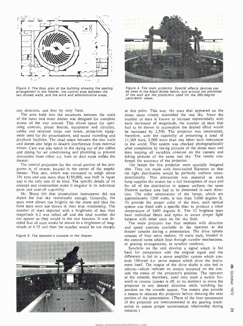
rti
Figure 2. The floor plan of the building showing the seating arrangement in the theater, the control area between the two domed walls, and the work and administrative areas.
one direction, and that by only 7mm. The area built into the structures between the walls
of the inner and outer domes was designed for complete access all the way around. This allows space for oper- ating controls, preset boards, equipment and circuitry, cables and terminal strips and boxes, projection equip- ment used for the presentations, and sound recording and playback facilities. The dead space between the two walls and domes also helps to deaden interference from external noises. Care was also taken in the laying out of the cables and piping for air conditioning and plumbing to prevent distraction from either a.c. hum or duct noise within the theater.
The central projection for the visual portion of the pro- grams is, of course, located in the center of the amphi- theater. This unit, which was estimated to weigh about 3'/4 tons and cost more than $150,000, was built in Japan and is the only one of its kind. The specific details of its concept and construction make it singular in its individual parts and over -all capability.
Mr. Sharp felt that planetarium instruments did not depict the real sky realistically enough. Generally, the stars were shown too brightly on the dome and thus the faint stars were not shown in their true relationship. The number of stars depicted with a brightness of less than magnitude 6.2 was rolled off and the total number did not appear as they would in the real heavens. It was de- cided that all stars would be shown to a brightness of mag- nitude of 6.75 and then the number would be cut sharply
Figure 3. The operator's console in the theater.
Figure 4. The main projector. Special effects devices can be seen in the black boxes below, and around the perimeter of the wall are the projectors used for the 360 -degree panoramic views.
at this point. This way, the stars that appeared on the dome more closely resembled the real sky. Since the number of stars is known to increase exponentially with each increment of magnitude, the number of stars that had to be shown to accomplish the desired effect would be increased by 2,500. The projector was constructed, therefore, with the capability of presenting a total of 11,369 stars, 2,000 more than any other such instrument in the world. This system was checked photographically after completion by taking pictures of the dome stars and then keeping all variables constant on the camera and taking pictures of the same real sky. The results con- firmed the accuracy of the projector.
The lamps for this projector were specially designed also. They are made with hand -coiled filaments so that the light distribution would be perfectly uniform omni- directionally. This precaution was essential as each lamp supplies the source for a full hemisphere of stars and for all of the distribution to appear uniform the same filament surface area had to be presented in each direc- tion. The color temperature of the lamps, which are approximately 1200 watts, is less than 3,000 degrees K. To provide the proper color of the stars, each optical system was fitted with a specific filter to produce a color temperature of 5400 degrees K. The 32 brightest stars have individual filters and optics to assure proper light balance with other stars on the sky field.
The main projector has four motions with direction and speed controls available to the operator at the theater console during a presentation. The drive system consists of four servo motors, 10 watts each, located in the control room which feed through transfer mechanisms, or gearing arrangements, to synchro resolvers.
Synchros on the unit develop a signal which is fed back for comparison with the original signal and the difference is fed to a servo amplifier system which con- trols 100 -watt d.c. servo motors which drive the instru- ment itself. The output of the drive shafts is also fed to selsyns -which indicate on meters mounted on the con- sole the status of the projector's position. The operator at the console, therefore, need only push a switch for- ward or reverse (center is off, or no motion) to move the projector in any desired direction while watching for position on the console meters. The meters also provide a means to relocate the projector before showing the next portion of the presentation. (Three of the four movements of the projector are interconnected in the gearing mech- anism to assure proper astronomical relationship during rotation.) N m
www.americanradiohistory.com
O CO
The slowest speed of rotation at which the projector can move is one revolution in 11/2 hours. The fastest is 1 rpm on three of the four movements and 3 rpm on the 4th. This 90:1 ratio is the widest relationship ever achieved on a device of this type. A protective circuit was also designed into the system so that if the projector is moving at a rapid pace in any one direction, an accidental signal to suddenly reverse its motion would automatically be rejected by the motor system and thus prevent any burn- out or failure in the mechanisms.
Although the celestial body projector is the largest and most costly of any of the visual devices used, it is only one of the several hundred units that are utilized during any of the regular presentations. There are twelve banks of ten projectors each, mounted in special cabinets built around the theater. These boxes are constructed outside of the theater wall itself in such a manner as to allow each projector to be aimed accurately at its area of cov- erage. The projected images provide a full 360 degree panorama around the base of the dome to depict a view of an ancient city, or the city sky -line, or any scene for which the slides are set up. The registration of each image must be precise to avoid any overlap of adjacent pictures. This is accomplished in the projectors by provid- ing each of the custom -built units with a thumbscrew arrangement which will hold the mounted slide still and in the precise position desired. The machines are fitted with cooling fans, ektagraphic optics, and use a 300 watt CAL lamp.
To provide uniformity of brightness all around the room and to be sure that the total image would accurately line up at all intersections, each of the projectors was checked for focal length and light output. The units were then positioned to provide the best possible viewing by the audience, with the best possible throw distance for
each unit. With each show running approximately three months, the relamping of each projector when the slides are changed has resulted in no burnouts and no down -time for any of the units.
Other projectors available for use in any presentation include 22 standard Carousel projectors using DEK (500 - watt) lamps, six super -8 continuous loop film projectors, five projectors for 16 mm film which use 200 -watt lamps, and sixty other projectors which utilize either 500 -watt quartz lamps or 18 -watt incandescents. In addition, there are six slide projectors located at the center of the theater, under the main projector, for casting montage images on the dome. Each of these units uses a DEK lamp and each is set up with a drum containing 81 slides. Each is operated by an automatic timer which is started at the proper spot in the presentation. The projection dis- tances are short for these projectors due to their location directly under the dome. To avoid excessive brightness of their images compared with other projectors, the optics on these projectors are closed down to the proper setting for projection balance.
There are also two random -access projectors available which are used primarily during presentations that are specially prepared for school classes. Each of these units is also provided with a full drum of 81 slides and is under the control of the lecturer or the operator in the rear control room.
In addition to the above equipment, 50 to 60 mini - projectors, made by the Minolta camera people, are nor- mally used during a typical presentation. These are no longer being made but a total of 200 are presently avail- able at the planetarium for use in whatever quantity or capacity required. They can be used with regular slides or for special effects. When used in this latter function, for example, various mechanical devices can be built into
The Quad /Eight Gate
The fast, accurate,
flexible
i
noise gate.
$98. Quad /eiglif elec[ronics 11929 Vose Street, North Hollywood. California 91605 Telephone: 213 /764 -1516
Circle 31 on Reader Service Card
www.americanradiohistory.com
the focal plane to produce image motions as required by the show. Electronic flash units can be substituted for the regular lamp and condensor lenses to produce lightning and other flashing effects.
Special devices are also used during shows as needed. There are five dissolve units, three of which can be used at any one time with the ektagraphic projectors. There are several dozen special projectors which have either been built from scratch as needed or are modified standard units. One unique device that was designed for a specific need is located at the center of the theater under the main projector. It consists of a slide projector on which is mounted a 16 mm film lens. The lens is a zoom type and is capable of remote control. The iris built into the optics was linked with the zoom mechanism so that as the image zoomed out to become larger and larger, the iris opened to provide more and more light. As the image zoomed in to a smaller size, the brightness was kept constant by the closing of the iris to cut some of the light along with the decrease of image size. The vari- able speed control lever on the console is moved in the direction of the desired zoom and has a center cut -off. A meter located on the console shows the operator the position of the zoom lens. This meter is a standard VU meter with the scale replaced by a more appropriate one.
Another special device that was custom built for use during presentations consists of a mechanism which will rotate a slide from an edge -on position to a full frontal view directly in line with the light source. The light itself is also mounted on a motor driven arm. This device per- mits effects such as showing a rotating galaxy at a dis- tance in oblique view and then having it come in toward the observer and simultaneously revolving to a full head - on view of the entire star system.
This extensive and complex visual display capability is
operated from the master console located at the rear of the theater and from a position in the rear control room. Access to the console operating area is from the rear control room only. As the operator enters the console area it surrounds him on three sides. On the left, the console has controls for the two random access projectors used in the school presentations, the start/stop and vol- ume controls for the program tape units, and a switch to turn on and off the public address amplifiers. There is no volume control for this system as the amplifiers have been preset to the maximum level output before feedback. This operation has proven very satisfactory.
At the center of the console, directly in front of the operator as he faces the celestial object projector, are a horizontal panel and three vertically inclined panels. At the center of the position there is a cutout for the oper- ator's program script. Controls on the vertical panels are for regulation of the brightness of planets, horizon glow, house lights, and also changes in latitude and processional. There are also controls for console lighting on this panel. The horizontal panel has controls for showing coordinates on the dome, individual dimmers for the sun, moon, and stars, and a master dimmer control. The horizontal panel also has controls for regulating the speed of heavenly motion through time such as the daily motion, and the orbital motion of the planets.
On the right side of the console, a myriad of variacs, potentiometers, and switches give the operator control of 24 power circuits with 1200 -watt capacity in each, control of six of the available fourteen circuit dimmers each capable of 6000 watts, and control of individual projectors as preset in the master -control area.
There are two arrow projectors also available for the operator at the console. These are specially wired to permit freedom of movement during the presentation-
Mixdown tonight. 16 track. How's your memory?
//////////11171t \\\\ The Number's Game.
compumx TM
Check our bingo number and in addition to complete technical data on Compumix I M we'll send you a free copy of "Automation Arithmetic - or How to Slice -up the Automation Pie ". It discusses the basics of digital information storage as applied to audio. We hope it will help you understand this new technology for sound recording.
Above, the CompumixTM controller. Our memory helper. Trust it. It's designed to interface any mixing console to our digital processor. 46" long, 16" deep, and 2" thick. Small. Everythings there. More than enough level and switching control for the heaviest 16 track mixdowns. Quad /eu1r1r elec[ron.cs
Circle 29 on Reader Service Card
www.americanradiohistory.com
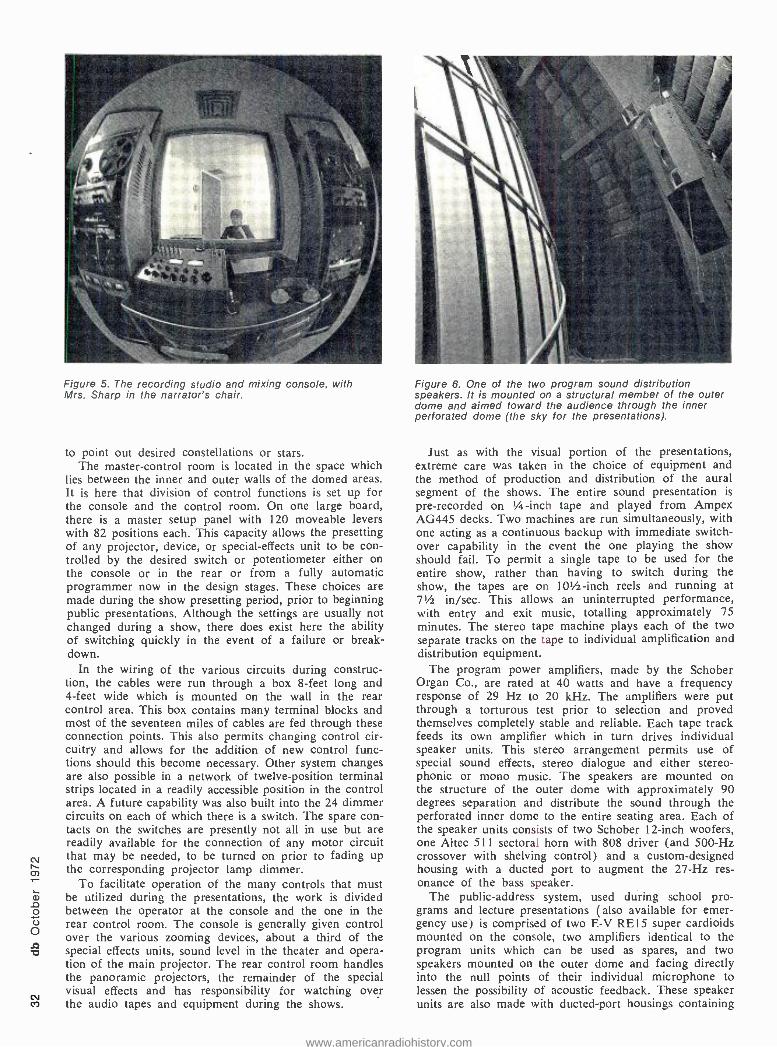
N M
Figure 5. The recording studio and mixing console, with Mrs. Sharp in the narrator's chair.
to point out desired constellations or stars. The master -control room is located in the space which
lies between the inner and outer walls of the domed areas. It is here that division of control functions is set up for the console and the control room. On one large board, there is a master setup panel with 120 moveable levers with 82 positions each. This capacity allows the presetting of any projector, device, or special -effects unit to be con- trolled by the desired switch or potentiometer either on the console or in the rear or from a fully automatic programmer now in the design stages. These choices are made during the show presetting period, prior to beginning public presentations. Although the settings are usually not changed during a show, there does exist here the ability of switching quickly in the event of a failure or break- down.
In the wiring of the various circuits during construc- tion, the cables were run through a box 8 -feet long and 4 -feet wide which is mounted on the wall in the rear control area. This box contains many terminal blocks and most of the seventeen miles of cables are fed through these connection points. This also permits changing control cir- cuitry and allows for the addition of new control func- tions should this become necessary. Other system changes are also possible in a network of twelve -position terminal strips located in a readily accessible position in the control area. A future capability was also built into the 24 dimmer circuits on each of which there is a switch. The spare con- tacts on the switches are presently not all in use but are readily available for the connection of any motor circuit that may be needed, to be turned on prior to fading up the corresponding projector lamp dimmer.
To facilitate operation of the many controls that must be utilized during the presentations, the work is divided between the operator at the console and the one in the rear control room. The console is generally given control over the various zooming devices, about a third of the special effects units, sound level in the theater and opera- tion of the main projector. The rear control room handles the panoramic projectors, the remainder of the special visual effects and has responsibility for watching over the audio tapes and equipment during the shows.
Figure 6. One of the two program sound distribution speakers. It is mounted on a structural member of the outer dome and aimed toward the audience through the inner perforated dome (the sky for the presentations).
Just as with the visual portion of the presentations, extreme care was taken in the choice of equipment and the method of production and distribution of the aural segment of the shows. The entire sound presentation is
pre -recorded on I -inch tape and played from Ampex AG445 decks. Two machines are run simultaneously, with one acting as a continuous backup with immediate switch - over capability in the event the one playing the show should fail. To permit a single tape to be used for the entire show, rather than having to switch during the show, the tapes are on 101/2-inch reels and running at 7' in /sec. This allows an uninterrupted performance, with entry and exit music, totalling approximately 75 minutes. The stereo tape machine plays each of the two separate tracks on the tape to individual amplification and distribution equipment.
The program power amplifiers, made by the Schober Organ Co., are rated at 40 watts and have a frequency response of 29 Hz to 20 kHz. The amplifiers were put through a torturous test prior to selection and proved themselves completely stable and reliable. Each tape track feeds its own amplifier which in turn drives individual speaker units. This stereo arrangement permits use of special sound effects, stereo dialogue and either stereo- phonic or mono music. The speakers are mounted on the structure of the outer dome with approximately 90 degrees separation and distribute the sound through the perforated inner dome to the entire seating area. Each of the speaker units consists of two Schober 12 -inch woofers, one Altec 511 sectoral horn with 808 driver (and 500 -Hz crossover with shelving control) and a custom- designed housing with a ducted port to augment the 27 -Hz res- onance of the bass speaker.
The public- address system, used during school pro- grams and lecture presentations (also available for emer- gency use) is comprised of two E -V RE15 super cardioids mounted on the console, two amplifiers identical to the program units which can be used as spares, and two speakers mounted on the outer dome and facing directly into the null points of their individual microphone to lessen the possibility of acoustic feedback. These speaker units are also made with ducted -port housings containing
www.americanradiohistory.com
E
a single Schober 12 -inch woofer, an 8 -inch mid -range speaker and a small high -frequency horn. In addition to the two inputs to this system from the console, there is a third from the open area of the 234 -seat theater to per- mit the lecturer standing in this location to be seen clearly by all the youngsters attending the special school presen- tations. The three mic inputs feed Automated Processes preamps.
The public- address system also has been wired up to feed a monitor speaker in the director's office and another monitor in the rear control area. This latter monitoring capability allows the console operator to throw a switch on the console to cut off the house p.a. speakers and talk directly to the personnel in the rear control room.
With the entire audio portion of the program on tape, all the recording and mixing is done by the planetarium technical staff in a studio specially built into the facility. The window for the separation of the studio from the re- cording control room is built into the wall of the outer domed area with the recording equipment and mixing console in the main control area. The microphones used consist of an E-V 664 and two E -V RE55's. The mixing console specially built for the requirements of the presen- tations, has six input positions and an additional switch- ing matrix permitting any six of a total of twenty sources to be fed into the console in stereo pairs. The console has two outputs and a separate vu meter on each.
The input sources available to the mixer, in addition to the microphones, are any of three mounted Revox tape machines or a portable unit, a turntable and an fm tuner. All recording is done on the Revox machines, and then mixed through the console, at 15 in /sec. After the music and sound effects have been put down on tape, the mix and a separate voice track are fed through the console into the theater. The best balance between the two is then worked out while listening in the area where the blend will be reproduced for the showing. It is only then that the final mix is made to the 71 in /sec. master reels. The mixing system has a response of 25 Hz- 25kHz. The ability to feed a tape through the console into the theater, separate from the two master tape decks, provides still another safety measure. In the event that both Ampex units become defective at the same time (which is unlikely since even the added precaution of separate power feeds has been incorporated into the wiring) the show can still go on from the mixing console with one of the Revox recorders.
In order to keep up with the latest in the audio field, a four -channel encoder has been installed in the sound rack in the control area. Although this is not in the sys- tem yet, it does provide the beginning of later improve- ments and additions to the sound system in a continuing attempt to enhance the enjoyment of the presentations.
Another example of the desire to enrich the effects of each of the shows, and the innovative capability used in the preparation of the program material, was evident in the very first presentation offered by the planetarium, called, appropriately, Beginnings. The birth of the uni- verse was depicted in this show, and it was desired by the production staff to have lightning and heavy claps of thunder. Pre -recorded material available at that time was found to be unsatisfactory. The two RE55's were run out to the outside and opposite ends of the building and mounted under shelter to wait for a thunder storm. After several such storms, and some close strikes of lightning, the desired sounds were recorded. The thunder reproduced at full level during the show left no doubt that this was the real sound.
Similarly, in the visual presentations, all slides are shot by the staff photographer and developed in the planetari- um's own lab to create the effects desired for the partic-
ular needs of the program. All art work for photographing is also developed by the staff artist.
Outside of the domed areas, in the lobby of the plan- etarium building, there is a display of transparencies showing various celestial objects. There are also two rear screen presentations using Carousel projectors with 8I- slide trays. In a glassed -off area near the center of the lobby, there is a telescope which is available to the public under the guidance of a staff member to view the real sky on clear nights -following the main evening presen- tation. Those members of the audience who prefer to listen to a talk on constellations are permitted to do so in the theater in lieu of looking through the telescope.
The telescope is built with two mirrors of Cer -Vit mate- rial which have a zero coefficient of expansion to ensure constant image quality under changing temperature con- ditions. The base for the unit was specially built separate from the main building by pouring an eight -ton concrete pier. The drive mechanism for the telescope is run by an audio oscillator and power amplifier and a synchro motor. There are five drive motors in all. Course adjustment is made by hand and fine control is electrical. Once the telescope is locked onto a star, the tracking is automatic. The 16 -inch aperture, 4 -meter focal length optics permit photography of stars to the 16th magnitude, and visual observation to about the 13th magnitude.
The entire project, right from its inception, has had meticulous care in all its phases. The innovations that have been and will be developed for improvement of the pres- entations will continue to provide visitors with realistic, entertaining, and exciting displays, for all members of the family. Reservations by calling the planetarium can be made all year round.
E (THIS IS NO BOOK FOR AMATEURS.)
Aof sWtlsdio(orbrauF:. SornamFdaeemernSn,ot!. 230.2SDnisfnn.GnmlR :"
It's crammed with pictures, poop, and prices. Features top grade electronics from around the world. Strictly for professional audio, broadcast, television, recording and motion picture moguls. We specialize in fast, off -the -shelf delivery on recorders. Duplicators. Micro-
phones. Turntables. Reverbs. Amplifiers. Attenuators. Equalizers. Compressors. Speakers. Broadcast and recording consoles. Write for your free copy of our catalog today.
AUDIO DISTRIBUTORS, INC. 2342 S. Division Avenue Grand Rapids, Michigan 49507
Circle 24 on Reader Service Card
w w
www.americanradiohistory.com

CO
HAM BROSIOUS
APRS -'72 The author details some of the highlights of this professional audio exposition which was held recently in London, England.
THE FIFTH ANNUAL EXHIBITION of professional re- cording equipment of the Association of Profes- sional Recording Studios was held at Connaught Rooms, in London, June 23 and 24. This event
is purely and simply an exhibition of equipment, with no meetings, papers, banquets, or other diversions to interfere with the business of demonstrating recording gear. From the manufacturers' viewpoint, this has some definite ad- vantages, such as maintaining high traffic throughout the exhibition day (11 a.m. to 11 p.m.).
U.S. equipment, generally represented by the U.K. dis- tributors, was much in evidence and included Crown, Shure, Koss, 3M, MCI, CBS Broadcast Products, Even- tide Clockworks, Burwen, Gotham, Moog, Switchcraft, Amphenol, Moog, Exedit, and JBL.
In touring the exhibition stands as the British call them instead of the familiar booths, one had to be struck with the move into manufacturing by studios large and small. Two very well known British Studios, Lansdowne and Trident, both were showing their highly sophisticated 24- track mixing desks (again using the British nomenclature) whle another big name in London studios, Orange, was getting a lot of attention to their 24 -track recorder, de- signed and built by their own engineers. By actual count, over twelve of the exhibitors were offsprings of recording studios.
Of the U. S. manufacturers, most interest was attracted by MCI, which shipped over a 16 -track and 24 -track recorder plus a 20 -track console. MCI president Jeep Harned and the author, the MCI exporter, were both on hand to plug their products.
New product interest centered for the most on some of the newer digital devices, such as digital delay lines, phasing devices, voltage -controlled attenuators and vari- ous noise reduction devices plus peak program meters, pulse modulation equalizers and mini mixers. A super mini mixer by Allen and Heath offers six inputs with stereo panning, three range equalization, echo send, and faders, and two outputs with vu meters, slider faders, and echo return equalization, and all for $395. Size: 71 x 10 x 1 inch ... how's that for a pint -sized package?
Ham Brosious is president of Audio - techniques, Inc. of Stamford, Connec- ticut. He was at APRS -'72 as both exhibitor and spectator.
In an overview, the APR '72 show seemed a lot like the AES during the Barbizon Plaza days; about the same number of exhibitors, slightly more attendance and really, not too much new but some interesting methods of ar- riving at the same place.
The exhibit was well attended by engineers from the continent, with France, Germany, and Belgium well rep- resented along with a good showing from the Scandinavian countries. If you can fit it into your travel plans next year, do it. You'll have a ball.
Dagmar Dolby and Do /by sales manager loan Allen deep in discussion -on what we didn't find out.
www.americanradiohistory.com
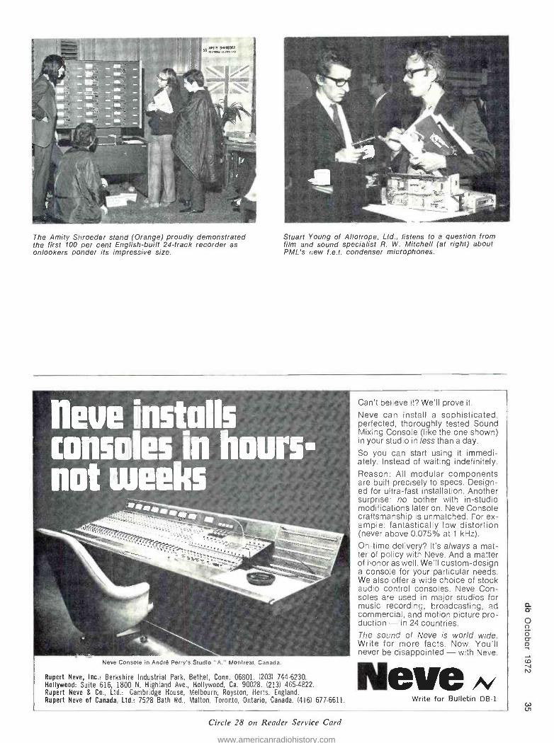
The Amity Shroeder stand (Orange) proudly demonstrated the first 100 per cent English -built 24 -track recorder as onlookers ponder its impressive size.
Stuart Young of Allotrope, Ltd., listens to a question from film and sound specialist R. W. Mitchell (at right) about PML's new f.e.t. condenser microphones.
heue installs consoles in hours not weeks
Neve Console in André Perry's Studio "A," Montreal, Canada.
Rupert Neve, Inc.: Berkshire Industrial Park, Bethel, Conn. 06801. (203) 744 -6230. Hollywood: Suite 616, 1800 N. Highland Ave., Hollywood, Ca. 90028. (213) 465.4822. Rupert Neve & Co., Ltd.: Cambridge House, Melbourn, Royston, Herts, England. Rupert Neve of Canada, Ltd.: 7528 Bath Rd.. Malton, Toronto, Ontario, Canada. (416) 677 -6611.
Can't believe it? We'll prove it.
Neve can install a sophisticated, perfected, thoroughly tested Sound Mixing Console (like the one shown) in your studio in less than a day.
So you can start using it immedi- ately. Instead of waiting indefinitely. Reason: All modular components are built precisely to specs. Design- ed for ultra -fast installation. Another surprise: no bother with in- studio modifications later on. Neve Console craftsmanship is unmatched. For ex- ample: fantastically low distortion (never above 0.075% at 1 kHz).
On -time delivery? It's always a mat- ter of policy with Neve. And a matter of honor as well. We'll custom -design a console for your particular needs. We also offer a wide choice of stock audio control consoles. Neve Con- soles are used in major studios for music recording, broadcasting, ad commercial, and motion picture pro- duction - in 24 countries. The sound of Neve is world wide. Write for more facts. Now. You'll never be disappointed - with Neve.
Neve Write for Bulletin DB -1
Circle 28 on Reader Service Card
Co cn
www.americanradiohistory.com
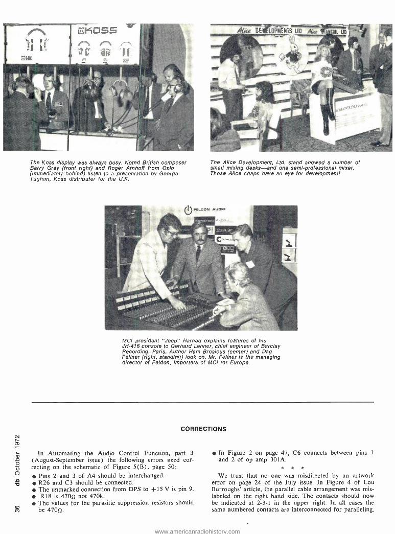
M
The Koss display was always busy. Noted British composer Barry Gray (front right) and Roger Arnhoff from Oslo (immediately behind) listen to a presentation by George Tughan, Koss distributer for the U.K.
The Alice Development, Ltd. stand showed a number of small mixing desks -and one semi- professional mixer. Those Alice chaps have an eye for development!
MCI president "Jeep" Harped explains features of his JH -416 console to Gerhard Lehner, chief engineer of Barclay Recording, Paris. Author Ham Brosious (center) and Dag Feltner (right, standing) look on. Mr. Feltner is the managing director of Feldon, importers of MCI for Europe.
CORRECTIONS
In Automating the Audio Control Function, part 3
(August- September issue) the following errors need cor- recting on the schematic of Figure 5(B), page 50:
Pins 2 and 3 of A4 should be interchanged. R26 and C3 should be connected. The unmarked connection from DPS to +15 V is pin 9. R18 is 470e not 470k.
The values for the parasitic suppression resistors should be 47052.
In Figure 2 on page 47, C6 connects between pins 1
and 2 of op amp 301A. * * *
We trust that no one was misdirected by an artwork error on page 24 of the July issue. In Figure 4 of Lou Burroughs' article, the parallel cable arrangement was mis- labeled on the right hand side. The contacts should now be indicated at 2 -3 -1 in the upper right. In all cases the same numbered contacts are interconnected for paralleling.
www.americanradiohistory.com
Martin Dickstein
SOUND WITH IMAGES
Convention Coverage
As indicated here in July, we were able to visit the VidExpo 72 Confer- ence held during the latter part of August at the Roosevelt Hotel in New York, and we hope that others of you were also able to attend. For those who could not, this brief report will attempt to bring you up to date on the talks and exhibits that were pre- sented. But, first, a word about the sponsor.
Billboard Publications, Inc., New York, publishes the magazine Bill- board, the leading international music/ record /tape newsweekly. They've done this for the past 78 years and have, in that time, expanded into other fields of communications, entertain- ment, and most recently, into video business. A quick look at the list of magazines published by BPI would show Vidnews, the biweekly video newsletter; Merchandising Week, the
only newsweekly for home electronics, housewares, and the major appliance industries; Photo Weekly, the only once -a -week business paper for the photo industry; High Fidelity, the monthly with which almost all hi -fi enthusiasts are familiar; and similar magazines in foreign countries. (In- cidentally, all of these publications were co -hosts of the conference.) BPI also publishes Modern Photography, Stereo, and other special- interest mag- azines; owns four catv systems in Massachusetts, a special -order record/ tape warehouse, and other enterprises in various communications areas; and also programs stereo entertainment for American Airlines, Air India, South African Airways, Pan Am World Airways, and Olympic Airlines. Now, with the birth of the video cassette -cartridge- disc -film market, BPI became involved in that direction, or-
ganized an international convention in this field in Europe, and followed up with VidExpo 72.
The conference was the first "user - oriented video marketplace," tuned to those who will use the media and equipment in this new field for indus- try, education, sales promotion, adver- tising, and for home distribution through catv and individual purchases. Four major divisions were discussed in the talks that were given and then in panel discussions: Government and the Video Media; Educational Video; Corporate Video; and Consumer Video. All are related to those who will be buying and using the hardware and software in various applications.
The keynote address in the Govern- ment category, Rep. Orval Hansen (R.- Idaho), Chairman of the GOP Task Force on Training and Educa- tion, revealed that he will introduce new legislation and announced that new funds would become available for educational programming. The new legislation would seek to estab- lish an Educational Technology Coun- cil in HEW.
During his talk, Rep. Hansen said: "My involvement with the educational aspects of television only dates back a few years but during that period of time I have grown accustomed to
"What I need is a recording console that's expandable to 26 in., 16/24 out; with full quad capability; and FET logic automatic rec. /play mode switching. But it would cost me $36,000 or more."
"What you need is Auditronicsl
VOA of 36 Grand 0 It's got everything you need for about half the cost."
For more information on the Son of 36 Grand, write Auditronics, P.O.
Box 12637, Mem- phis, Tenn. 38112.
1 lil
Circle 19 on Reader Service Card
ouditronics. inc. M E M P H I S T E N N E S S E E
Co)
www.americanradiohistory.com
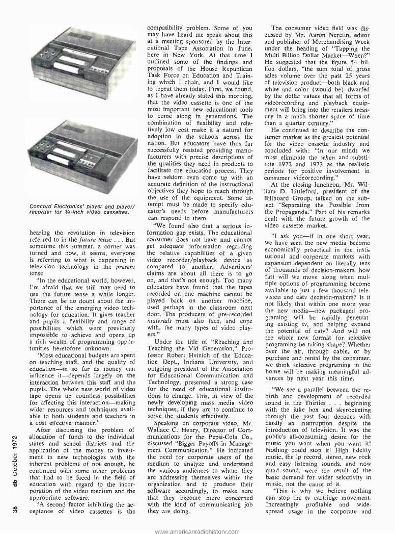
Concord Electronics' player and player/ recorder for 3 -inch video cassettes.
hearing the revolution in television referred to in the future tense . .. But sometime this summer, a corner was turned and now, it seems, everyone is referring to what is happening in television technology in the present tense
"In the educational world, however, I'm afraid that we still may need to use the future tense a while longer. There can be no doubt about the im- portance of the emerging video tech- nology for education. It gives teacher and pupils a flexibility and range of possibilities which were previously impossible to achieve and opens up a rich wealth of programming oppor- tunities heretofore unknown.
"Most educational budgets are spent on teaching staff, and the quality of education -in so far as money can influence it- depends largely on the interaction between this staff and the pupils. The whole new world of video tape opens up countless possibilities for affecting this interaction- making wider resources and techniques avail- able to both students and teachers in a cost effective manner."
After discussing the problem of allocation of funds to the individual states and school districts and the application of the money to invest- ment in new technologies with the inherent problems of not enough, he continued with some other problems that had to be faced in the field of education with regard to the incor- poration of the video medium and the appropriate software.
"A second factor inhibiting the ac- ceptance of video cassettes is the
compatibility problem. Some of you may have heard me speak about this at a meeting sponsored by the Inter- national Tape Association in June, here in New York. At that time I outlined some of the findings and proposals of the House Republican Task Force on Education and Train- ing which I chair, and I would like to repeat them today. First, we found, as I have already stated this morning, that the video cassette is one of the most important new educational tools to come along in generations. The combination of flexibility and rela- tively low cost make it a natural for adoption in the schools across the nation. But educators have thus far successfully resisted providing manu- facturers with precise descriptions of the qualities they need in products to facilitate the education process. They have seldom even come up with an accurate definition of the instructional objectives they hope to reach through the use of the equipment. Some at- tempt must be made to specify edu- cator's needs before manufacturers can respond to them.
"We found also that a serious in- formation gap exists. The educational consumer does not have and cannot get adequate information regarding the relative capabilities of a given video recorder /playback device as compared to another. Advertisers' claims are about all there is to go on, and that's not enough. Too many educators have found that the tapes recorded on one machine cannot be played back on another machine, used perhaps in the classroom next door. The producers of pre- recorded materials must also face, and cope with, the many types of video play- ers."
Under the title of "Reaching and Teaching the Vid Generation," Pro- fessor Robert Heinich of the Educa- tion Dept., Indiana University, and outgoing president of the Association for Educational Communication and Technology, presented a strong case for the need of educational institu- tions to change. This, in view of the newly developing mass media video techniques, if they are to continue to serve the students effectively.
Speaking on corporate video, Mr. Wallace C. Henry, Director of Com- munications for the Pepsi -Cola Co., discussed "Bigger Payoffs in Manage- ment Communication." He indicated the need for corporate users of the medium to analyze and understand the various audiences to whom they are addressing themselves within the organization and to produce their software accordingly, to make sure that they become more concerned with the kind of communicating job they are doing.
The consumer video field was dis- cussed by Mr. Aaron Neretin, editor and publisher of Merchandising Week under the heading of "Tapping the Multi Billion Dollar Market - When ?" He suggested that the figure 54 bil- lion dollars, "the sum total of gross sales volume over the past 25 years of television product -both black and white and color (would be) dwarfed by the dollar values that all forms of videorecording and playback equip- ment will bring into the retailers treas- ury in a much shorter space of time than a quarter century."
He continued to describe the con- sumer market as the greatest potential for the video cassette industry and concluded with: "In our minds we must eliminate the when and substi- tute 1972 and 1973 as the realistic periods for positive involvement in consumer videorecording."
At the closing luncheon, Mr. Wil- liam D. Littleford, president of the Billboard Group, talked on the sub- ject "Separating the Possible from the Propaganda." Part of his remarks dealt with the future growth of the video cassette market.
"I ask you -if in one short year, we have seen the new media become economically proactical in the insti. tutional and corporate markets with expansion dependent on literally tens of thousands of decision -makers, how fast will we move along when mul- tiple options of programming become available to just a few thousand tele- vision and catv decision- makers? Is it not likely that within one more year the new media -new packaged pro- graming -will be rapidly penetrat- ing existing tv, and helping expand the potential of catv? And will not the whole new format for selective programing be taking shape? Whether over the air, through cable, or by purchase and rental by the consumer, we think selective programing in the home will be making meaningful ad- vances by next year this time.
"We see a parallel between the re- birth and development of recorded sound in the Thirties . . . beginning with the juke box and skyrocketing through the past four decades with hardly an interruption despite the introduction of television. It was the public's all- consuming desire for the music you want when you want it! Nothing could stop it! High fidelity music, the 1p record, stereo, new rock and easy listening sounds, and now quad sound, were the result of the basic demand for wider selectivity in music, not the cause of it.
"This is why we believe nothing can stop the tv cartridge movement. Increasingly profitable and wide- spread usage in the corporate and
www.americanradiohistory.com
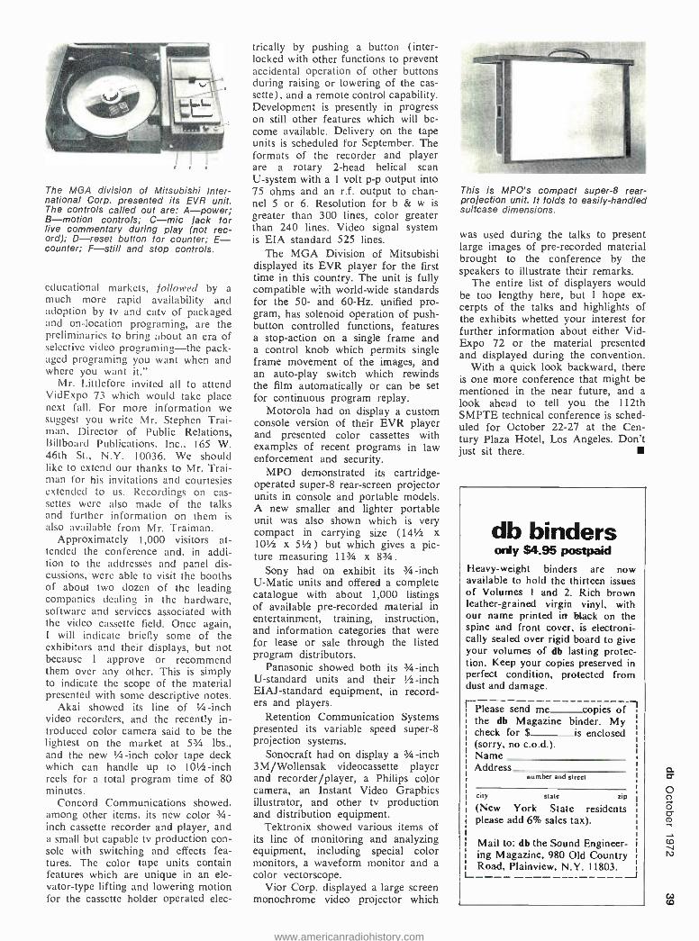
The MGA division of Mitsubishi Inter- national Corp. presented its EVR unit. The controls called out are: A- power; B- motion controls; C -mic jack for live commentary during play (not rec- ord); D -reset button for counter; E- counter; F -still and stop controls.
educational markets, followed by a much more rapid availability and adoption by tv and catv of packaged and on- location programing, are the preliminaries to bring about an era of selective video programing the pack- aged programing you want when and where you want it."
Mr. Littlefore invited all to attend VidExpo 73 which would take place next fall. For more information we suggest you write Mr. Stephen Trai- man, Director of Public Relations, Billboard Publications, Inc., 165 W. 46th St., N.Y. 10036. We should like to extend our thanks to Mr. Trai- man for his invitations and courtesies extended to us. Recordings on cas- settes were also made of the talks and further information on them is also available from Mr. Traiman.
Approximately 1,000 visitors at- tended the conference and, in addi- tion to the addresses and panel dis- cussions, were able to visit the booths of about two dozen of the leading companies dealing in the hardware, software and services associated with the video cassette field. Once again, I will indicate briefly some of the exhibitors and their displays, but not because I approve or recommend them over any other. This is simply to indicate the scope of the material presented with some descriptive notes.
Akai showed its line of 1/4-inch video recorders, and the recently in- troduced color camera said to be the lightest on the market at 53/4 lbs., and the new 1/4 -inch color tape deck which can handle up to 101/2-inch reels for a total program time of 80 minutes.
Concord Communications showed, among other items, its new color 3 /.t- inch cassette recorder and player, and a small but capable tv production con- sole with switching and effects fea- tures. The color tape units contain features which are unique in an ele- vator -type lifting and lowering motion for the cassette holder operated elec-
trically by pushing a button (inter- locked with other functions to prevent accidental operation of other buttons during raising or lowering of the cas- sette), and a remote control capability. Development is presently in progress on still other features which will be- come available. Delivery on the tape units is scheduled for September. The formats of the recorder and player are a rotary 2 -head helical scan U- system with a 1 volt p -p output into 75 ohms and an r.f. output to chan- nel 5 or 6. Resolution for b & w is greater than 300 lines, color greater than 240 lines. Video signal system is EIA standard 525 lines.
The MGA Division of Mitsubishi displayed its EVR player for the first time in this country. The unit is fully compatible with world -wide standards for the 50- and 60 -Hz. unified pro- gram, has solenoid operation of push- button controlled functions, features a stop- action on a single frame and a control knob which permits single frame movement of the images, and an auto -play switch which rewinds the film automatically or can be set for continuous program replay.
Motorola had on display a custom console version of their EVR player and presented color cassettes with examples of recent programs in law enforcement and security.
MPO demonstrated its cartridge - operated super -8 rear -screen projector units in console and portable models. A new smaller and lighter portable unit was also shown which is very compact in carrying size (141/2 x 101/2 x 51/2) but which gives a pic- ture measuring 113/4 x 83/4.
Sony had on exhibit its 3/4 -inch U -Matie units and offered a complete catalogue with about 1,000 listings of available pre- recorded material in entertainment, training, instruction, and information categories that were for lease or sale through the listed program distributors.
Panasonic showed both its 3/4 -inch U- standard units and their 1/2-inch EIAJ- standard equipment, in record- ers and players.
Retention Communication Systems presented its variable speed super -8 projection systems.
Sonocraft had on display a 3/4 -inch 3M /Wollensak videocassette player and recorder /player, a Philips color camera, an Instant Video Graphics illustrator, and other tv production and distribution equipment.
Tektronix showed various items of its line of monitoring and analyzing equipment, including special color monitors, a waveform monitor and a color vectorscope.
Vior Corp. displayed a large screen monochrome video projector which
This is MPO's compact super -8 rear - projection unit. It folds to easily- handled suitcase dimensions.
was used during the talks to present large images of pre- recorded material brought to the conference by the speakers to illustrate their remarks.
The entire list of displayers would be too lengthy here, but I hope ex- cerpts of the talks and highlights of the exhibits whetted your interest for further information about either Vid- Expo 72 or the material presented and displayed during the convention.
With a quick look backward, there is one more conference that might be mentioned in the near future, and a look ahead to tell you the 112th SMPTE technical conference is sched- uled for October 22 -27 at the Cen- tury Plaza Hotel, Los Angeles. Don't just sit there.
db binders only $4.95 postpaid
Heavy- weight binders are now available to hold the thirteen issues of Volumes I and 2. Rich brown leather- grained virgin vinyl, with our name printed in black on the spine and front cover, is electroni- cally sealed over rigid board to give your volumes of db lasting protec- tion. Keep your copies preserved in perfect condition, protected from dust and damage.
EPlease send me copies of, the db Magazine binder. My check for $ is enclosed s
(sorry, no c.o.d.). Name Address
number and street
city state zip
(New York State residents please add 6% sales tax).
Mail to: db the Sound Engineer- i
ing Magazine, 980 Old Country Road, Plainview, N.Y. 11803.
w
www.americanradiohistory.com

As a service to our readers we are pleased to offer books from prominent technical publishers. All prices listed are the publishers' net. Shipping charges are Included.
To order use the coupon at the bottom of the page. Indicate quantity on the special Instructions line
ro)3(10D
If more than one copy of a title Is wanted. Full payment must accompany your order. We cannot ship c.o.d. Checks or money orders should be made payable to Sagamore Publishing Company, Inc. Because of the time required to process orders, allow several weeks for the receipt of books.
20. The Audio Cyclopedia (2nd ed.). Dr. Howard M. Tremaine. New and updated, here is the complete audio reference li- brary in a single volume. It provides the most comprehensive information on every aspect of the audio art. This new edition includes the latest audio developments in- cluding the most recent solid -state systems and integrated circuits. It covers all sub- jects in the fields of acoustics, recording, and reproduction with more than 3400 re- lated topics. Each topic can be instantly located by a unique index and reference system. More than 1600 illustrations and schematics help make complicated topics masterpieces of clarity. 1760 pages; 61/2 x 9% hardbound. $29.95
1. The Technique of the Sound Studio. Alec Nisbett. This is a handbook on radio and recording techniques, but the princi- ples described are equally applicable to film and television sound. 264 pages; 60 diagrams; glossary; indexed; 51/2 x 81/2;
clothbound. $14.50
7. Acoustical Tests and Measurements. Don Davis. Provides solid understanding of the entire subject of acoustical measure- ments; based on actual field test work, using commercial equipment. 192 pages; 51/2 x 81/2; hardbound. $6.95
8. Handbook of Electronic Tables & Formulas, (3rd edition). A one -stop source for all charts, tables, formulas, laws, sym- bols, and standards used in electronics. In- cludes an 8 -page, full -color fold -out chart showing latest FCC allocations for the en- tire frequency spectrum. 232 pages; 51/2 x 81; hardbound. $5.50
Sagamore Publishing Company, Inc. 980 Old Country Road, Plainview, N.Y. 11803
Please send me the books I have circled below. My full remittance in the amount of $ is enclosed. N.Y. State resi- dents add 7% sales tax.
1 2 3 4 5 6 7 8 9 10 11
12 13 14 15 16 17 18 19 20 21 22 23 24 25 26 27 28 29 30 31 32 33 34 35 36 37 38 39 40
Name
Address
City
State Zip Special Instructions
°v Canada and foreign: Add $1.00 per book
24. Basic Electronic Instrument Handbook. Edited by Clyde F. Coombs, Jr. Hewlett - Packard Co. A basic reference background for all instruments. Offers saving in time and effort by having complete information in one volume on how to get the most bene- fit from available devices, how to buy the best instrument for specific needs. Reduces chances of costly errors. Ideal reference book, it is an excellent source for the be- ginner, technician, the non -electrical en- gineering man, or general non -engineering scientific and technical personnel. 800 pages. Hardbound. $28.50
25. Operational Amplifiers- Design and Applications. Burr -Brown Research Corp. A comprehensive new work devoted en- tirely to every aspect of selection, use, and design of op amps -from basic theory to specific applications. Circuit design tech- niques including i.c. op amps. Applica- tions cover linear and non -linear circuits, A/D conversion techniques, active filters, signal generation, modulation and de- modulation. Complete test circuits and methods. 474 pages. $15.00
26. The Design of Digital Systems. John B. Peatman. Textbook for students desiring to develop a creative approach design capa- bility through digital systems approach. Answers these question: Under what cir- cumstances it is desirable to implement a
system digitally? What are some of the components available for implementing the system? How do we go about design- ing it? 448 pages. $15.50
31. Solid -State Electronics. Hibberd. A Basic Course for Engineers and Techni- cians. An extremely practical reference book for anyone who wants to acquire a good but general understanding of semi- conductor principles. Features questions and answers, problems to solve. 1968. 169 pp. $9.95
32. Circuit Design for Audio, AM /FM, and TV. Texas Instruments. Texas Instruments Electronics Series. Discusses the latest ad- vances in design and application which represent the results of several years re- search and development by TI communica- tions applications engineers. Emphasizes time- and cost -saving procedures. 1967. 352 pp. $14.50
35. An Alphabetical Guide to Motion Picture, Television, and Videotape Produc- tions. Levitan. This all- inclusive, authorita- tive, and profusely illustrated encyclopedia is a practical source of information about techniques of all kinds used for making and processing film and TV presentations. Gives full technical information on mate- rials and equipment, processes and tech- niques, lighting, color balance, special effects, animation procedures, lenses and filters, high -speed photography, etc: 1970. 480 pp. $24.50
40. Radio Transmitters. Gray and Graham. Provides, in a logical, easy -to- understand manner, a working knowledge of radio transmitters for quick solution of problems in operation and maintenance. 1961. 462 PP. $16.00
23. Wide Screen Cinema & Stereophonic Sound. M.Z. Wystozky. First published in USSR in 1965 this excellent English trans- lation covers wide gauge films, panoramic films, circular panoramic cinematography; technical fundamentals of stero sound re- cording for film, as well as details of the Soviet systems now in use. 284 pages.
$15.00
33. Noise Reduction. Beranek. Designed for the engineer with no special training in acoustics, this practical text on noise control treats the nature of sound and its measurement, fundamentals of noise con- trol, criteria, and case histories. Covers advanced topics in the field. 1960. 752 pp.
$19.50
27. Noise & Vibration Control. Edit. by Leo L. Beranek. Practical design and reg- ulatory information; formulas, choice of materials and structures, city codes and hearing protection; indispensable for de- sign engineers, public officials who prepare regulations for noise control, safety and environmental engineers involved in noise and vibration controls. Covers data analysis, transmission of sound, psychophysiological design criteria, hearing damage risk, etc: Wealth of detail, comprehensive index and concise appendices. 650 pages. $29.50
28. Environmental Acoustics. Leslie L. Doelle. Applied acoustics for those in envi- ronmental noise control who lack spe- cialized acoustical training. Basic informa- tion in comprehensible and practical form for solving straightforward problems. Ex- plains fundamental concepts; pure theory minimized. Practical applications stressed, acoustical properties of materials and con- struction listed, actual installations with photos and drawings. Appendixes illustrate details of 53 wall types and 32 floor plans and other useful data. 246 pgs. $18.50
21. Acoustics -Room Design and Noise Control. Michael Rettinger. 1968. The enormous problems and hazards presented by noise are dealt within an orderly and practical manner. With many charts, graphs, and practical examples, the text covers the physics of sound, room acous- tics, and design, noise and noise reduc- tion. 392 pages. $17.50
22. Acoustics of Studios and Auditoria. V.S. Mankovsky. Basic theory plus a mass of design data covers the field with special reference to studios and places of public performance. For acoustical designers and specialists in sound transmission in cinema and broadcasting. Features exhaustive treatment of studio acoustics by the sta- tistical, geometric and wave methods in parallel. 416 pgs. $15.00
www.americanradiohistory.com

CLASSIFIED
FOR SALE
FOR SALE: Crown CX -822 tape recorder, accessories. (215) 667 -3048.
SCULLY 284 -8 RECORDER. Mint condi- tion very low hours with sync master, $8,000 fob Omaha. Contact Grant Scha- inost, Sound Recorders, (402) 553- 1164.
AMERICA'S LARGEST SELECTION of new and used broadcast and recording equipment! Latest bulletins available. The Maze Corporation, P.O. Box 6636, Birmingham, Ala. 35210.
WHATEVER YOUR EQUIPMENT NEEDS -new or used -check us first. Trade your used equipment for new. Write for our complete listings. Broadcast Equip- ment 8 Supply Co., Box 3141, Bristol, Tenn. 37620.
SOLID -STATE AUDIO MODULES. Con- sole kits, power amplifier kits, power supplies. Octal plug- ins -mic, eq, line, disc, tape play, tape record, amplifiers. Audio and tape bias oscillators. Over 50 audio products, send for free catalog and applications. Opamp Labs. Inc., 172 So. Alta Vista Blvd., Los Angeles, Ca. 90036. (213) 934 -3566.
HAECO announces complete repair ser- vice and overhaul for all Westrex cut - terheads. Conversions of 3D -II and old- er models to higher performance stand- ards and reliability. Helium cooling systems and hi -temp coils can protect your investment. Repair insurance pro- gram available. Rapid service. Lower cost. HAECO, 14110 Aetna, Van Nuys, California 91401.
SCULLY TAPE RECORDERS -one to twenty -four track and model 270 auto players, many models in stock for im- mediate delivery. SCULLY LATHES - Previously owned and rebuilt. Variable or automatic pitch. Complete cutting systems with Westrex heads. MIXING CONSOLES -Custom designed using Weigand Audio Lab modules. From $7,000.00. Weigand Audio Laboratories, R.D. 3, Middleburg, Pa. 17842. Phone
(717) 837 -1444.
CATV -MATV PRODUCTS CONNECTORS WALLPLATES SPLITTERS AMPLIFIERS wv
.AVA ELECTRONICS CORP. 416 LONG LANE. UPPER DARBY PA. 19082
1. 9.0C
IN THE NORTHEAST it's Audiotech- niques for MCI 8 -16 -24 track recorders and mixing consoles. The performance is superb, the price is right and the delivery is fast! What else do you want'? You're right ... service! That's Bob Ber - liner's job, and there's none better. Audiotechniques, 121 Hamilton Avenue, Stamford, Conn. 06902. (203) 359- 2312.
COMPLETE DISC CUTTING SYSTEM. Eq. filter, limiter, amps, 605B speaker, jack bays, Grampian head and amp in
rack and Ampex 350 -1C: $3300.00. Plastic tape hold downs: $15.00. Wash- burn Co., 6114 Santa Monica Blvd., Hollywood, Ca. 90038.
AMPEX 602 TRANSPORT with Ampex AG -600 series 1/a -track head assembly. Like new. $512 value for $230. More items -send for list. RDD, 1807 Elm - crest, Arlington, Texas 76012.
AUDIO DESIGNS CONSOLE -sixteen in- put, 8/16 output. Audex program and echo bus assignment. Quad monitoring both studio and control room with Au- dex tape track to speaker assignment. Quad outputs. Sixteen -track monitor mix. Four equalized echo busses. Two cue busses. $16,000. Sound 80, (612) 721- 6341.
TELETRONIX LIMITER, Pultec's Fair- child 523 -J1 lathe Neumann cutter, Mac 200 watt. Best offer. Bradley Recording, 531 N. Howard Street, Baltimore, Md. 21201. (301) 727 -0950.
EXCLUSIVELY IN USA "Satin" moving coil cartridges. Impedance matches mag- netic input. M14LE (elliptical) $99.95, M14LX (Shibata) $129.95. Send check to Michael -Scott Enterprises, Room 24, 6056 West Broadway, Minneapolis, Minn. 55422.
AUDIO EQUIPMENT, new and used. Custom consoles built to your specifica- tions using the components of your choice. Whether you're building a new studio or remodeling your present one, check us first for a package price. Am- boy Audio Associates, 236 Walnut Street, South Amboy, N.J. 08879. (201) 721 -5121.
SCULLY 284 -8, excellent condition, with sync master. Console 20 by 4 custom built using Electrodyne 710LC modules; three complimiters; monitor panel, (stereo mix with separate cue mix). Call or write Synchron Sound Studios, Inc., 10 George Street, Wallingford, Conn. 06492. (203) 269 -4465.
IN THE NORTHEAST it's Audiotechniques for STANDARD TAPE LABORATORY test tapes. We think they're the most depend- able, accurate reference tapes available. Call Ham Brosious or Bob Berliner and find out why. Audiotechniques, 121 Hamil- ton Avenue, Stamford, Conn. 06902. Phone (203) 359 -2312.
LIKE NEW AMPEX 1/2 -inch, 4 -track heads and assembly (erase, record, playback). 300 series. Best offer. Continental Re- cordings, 12 Irving Square, Framing- ham, Mass. 01701. (617) 879 -2430.
CLOVER SYSTEMS announces the intro- duction of a complete line of unique stock and custom consoles. Write or call for information regarding our com- plete line of hardware and services, in- cluding complete turn -key studio instal- lations. Clover Systems, 12970 Branford St., Arleta, Ca. 91331. (213) 768 -2100.
MUST SELL: Langevin 25 input (switch - able to 75 input) four output board. Slid- ers, complete equalization on each input -ideal for remote truck. New cost $17,000, sacrifice for $13,000. Also stereo Dolby, UREI limiters, Fairchild stereo limiter, Fairchild reverb, McIntosh ampli- fiers, various microphones at reasonable prices. Also available, Scully 16 track with sync, digital counter; Scully two - track; Ampex full track AG -600. Call (206) 392 -2493 after six p.m. Pacific time.
NEW YORK'S LEADING supplier of pro- fessional audio /video equipment and hi -fi stereo components. All major brands in stock. Call for quote- sales -service- leasing -trade -ins. Martin Audio, 320 West 36th Street, New York, N.Y. 10036. Telephone: (212) 265 -6400.
AMPEX 601 full track 71/2 in /sec. In
immaculate condition. Totally operating. Heads moderately worn. $100.00 Orban/ Parasound Reverberation model 105C. In perfect condition. One year old. Built - in attack limiter. $250.00. Different Fur Studios, 3470 19th Street, San Fran- cisco, Ca. 94110. (415) 864 -1967.
SPECIAL -NEW FIDELIPAC NAB cart- ridges, 10 secs to 6 minutes. Only $1.25 each. Minimum quantity 50 carts. Specify lengths when ordering. Gately Electron- ics, 57 W. Hillcrest Avenue, Havertown, Pa. 19083.
FM TUNER /RECEIVER alignment. Free checkout for distortion, frequency re- sponse, separation (see June -July 1970 issues of Audio). Complete FM tuner alignment $20 plus parts. One year guarantee. FOB A. L. Boynton, 369 Aklan Ct., San Jose, Ca. 95119.
ONE STOP FOR ALL your professional audio requirements. Bottom line ori- ented. F.T.C. Brewer Company, P.O. Box 8057, Pensacola, Florida 32505.
EMPLOYMENT
PROFESSIONAL RECORDING PERSON- NEL SPECIALISTS. A service for 'em- ployers and job seekers. Call today) Smith's Personnel Service, 1457 Broad- way, N.Y.C. 10036. Alayne Spertell 212 Wi 7 -3806.
www.americanradiohistory.com
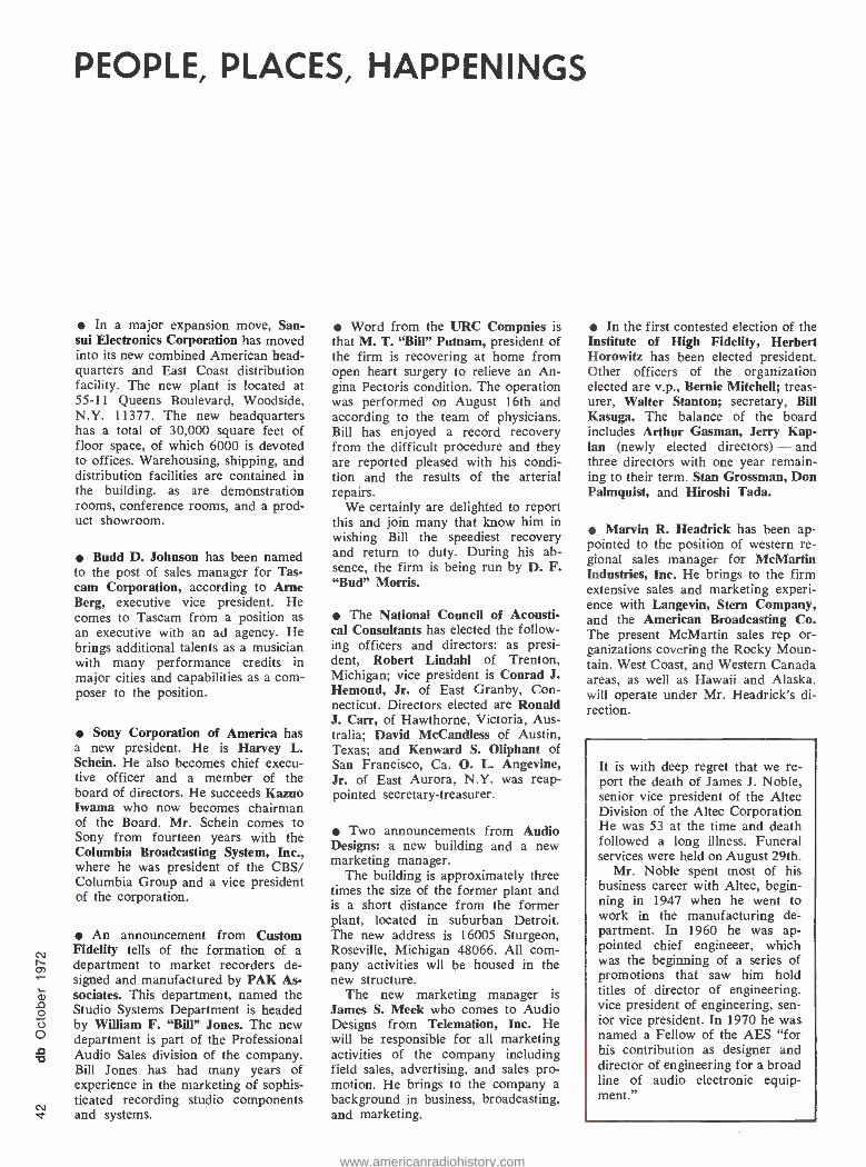
N v
PEOPLE, PLACES, HAPPENINGS
In a major expansion move, San - sui Electronics Corporation has moved into its new combined American head- quarters and East Coast distribution facility. The new plant is located at 55 -11 Queens Boulevard, Woodside, N.Y. 11377. The new headquarters has a total of 30,000 square feet of floor space, of which 6000 is devoted to offices. Warehousing, shipping, and distribution facilities are contained in the building, as are demonstration rooms, conference rooms, and a prod- uct showroom.
Budd D. Johnson has been named to the post of sales manager for Tas- cam Corporation, according to Arne Berg, executive vice president. He comes to Tascam from a position as an executive with an ad agency. He brings additional talents as a musician with many performance credits in major cities and capabilities as a com- poser to the position.
Sony Corporation of America has a new president. He is Harvey L. Schein. He also becomes chief execu- tive officer and a member of the board of directors. He succeeds Kazuo Iwama who now becomes chairman of the Board. Mr. Schein comes to Sony from fourteen years with the Columbia Broadcasting System, Inc., where he was president of the CBS/ Columbia Group and a vice president of the corporation.
An announcement from Custom Fidelity tells of the formation of a department to market recorders de- signed and manufactured by PAK As- sociates. This department, named the Studio Systems Department is headed by William F. "Bill" Jones. The new department is part of the Professional Audio Sales division of the company. Bill Jones has had many years of experience in the marketing of sophis- ticated recording studio components and systems.
Word from the URC Compnies is that M. T. `Bill" Putnam, president of the firm is recovering at home from open heart surgery to relieve an An- gina Pectoris condition. The operation was performed on August 16th and according to the team of physicians, Bill has enjoyed a record recovery from the difficult procedure and they are reported pleased with his condi- tion and the results of the arterial repairs.
We certainly are delighted to report this and join many that know him in wishing Bill the speediest recovery and return to duty. During his ab- sence, the firm is being run by D. F. "Bud" Morris.
The National Council of Acousti- cal Consultants has elected the follow- ing officers and directors: as presi- dent, Robert Lindahl of Trenton, Michigan; vice president is Conrad J. Hemond, Jr. of East Granby, Con- necticut. Directors elected are Ronald J. Carr, of Hawthorne, Victoria, Aus- tralia; David McCandless of Austin, Texas; and Kenward S. Oliphant of San Francisco, Ca. O. L. Angevine, Jr. of East Aurora, N.Y. was reap- pointed secretary -treasurer.
Two announcements from Audio Designs: a new building and a new marketing manager.
The building is approximately three times the size of the former plant and is a short distance from the former plant, located in suburban Detroit. The new address is 16005 Sturgeon, Roseville, Michigan 48066. All com- pany activities wit be housed in the new structure.
The new marketing manager is James S. Meek who comes to Audio Designs from Telemation, Inc. He will be responsible for all marketing activities of the company including field sales, advertising, and sales pro- motion. He brings to the company a background in business, broadcasting, and marketing.
In the first contested election of the Institute of High Fidelity, Herbert Horowitz has been elected president. Other officers of the organization elected are v.p., Bernie Mitchell; treas- urer, Walter Stanton; secretary, Bill Kasuga. The balance of the board includes Arthur Gasman, Jerry Kap- lan (newly elected directors) - and three directors with one year remain- ing to their term, Stan Grossman, Don Palmquist, and Hiroshi Tada.
Marvin R. Headrick has been ap- pointed to the position of western re- gional sales manager for McMartin Industries, Inc. He brings to the firm extensive sales and marketing experi- ence with Langevin, Stern Company, and the American Broadcasting Co. The present McMartin sales rep or- ganizations covering the Rocky Moun- tain, West Coast, and Western Canada areas, as well as Hawaii and Alaska. will operate under Mr. Headrick's di- rection.
It is with deep regret that we re- port the death of James J. Noble, senior vice president of the Altec Division of the Altec Corporation He was 53 at the time and death followed a long illness. Funeral services were held on August 29th.
Mr. Noble spent most of his business career with Altec, begin- ning in 1947 when he went to work in the manufacturing de- partment. In 1960 he was ap- pointed chief engineeer, which was the beginning of a series of promotions that saw him hold titles of director of engineering, vice president of engineering, sen- ior vice president. In 1970 he was named a Fellow of the AES "for his contribution as designer and director of engineering for a broad line of audio electronic equip- ment."
www.americanradiohistory.com
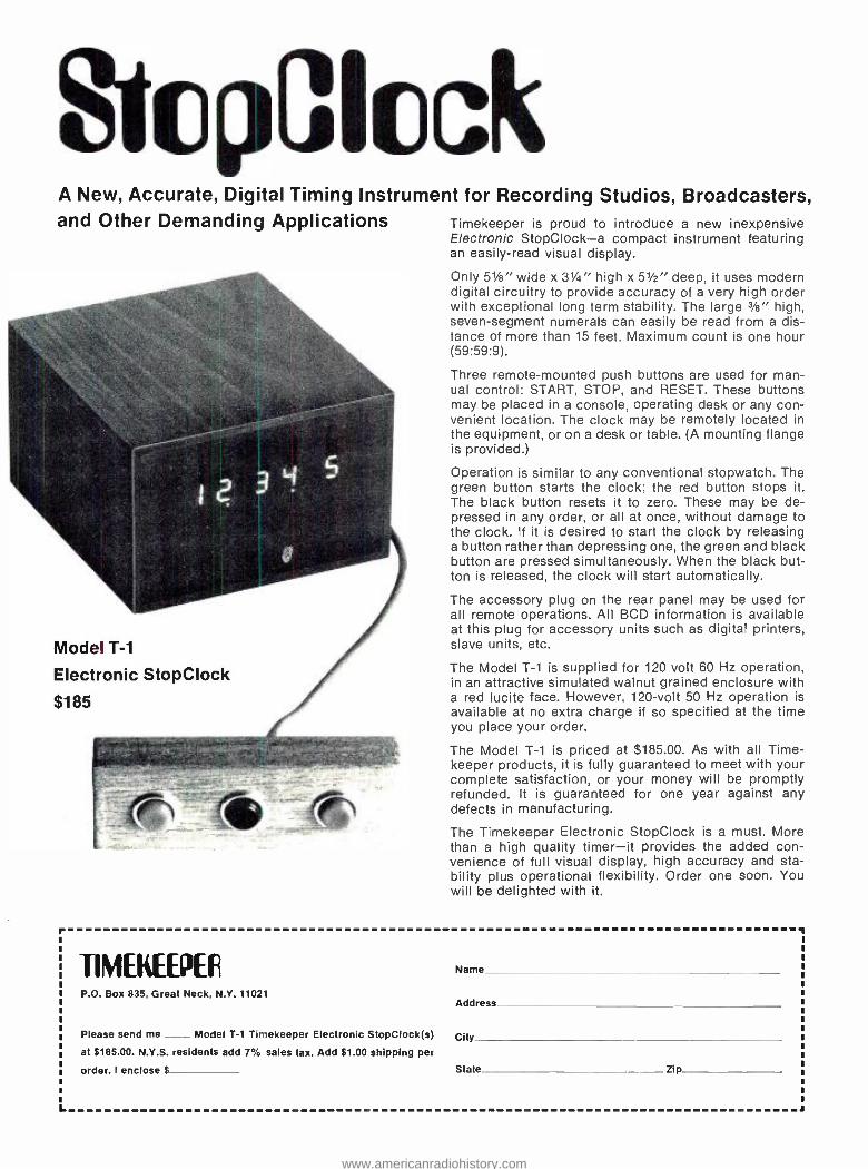
StopClock A New, Accurate, Digital Timing Instrument for Recording Studios, Broadcasters, and Other Demanding Applications Timekeeper is proud to introduce a new inexpensive
Electronic StopClock -a compact instrument featuring an easily -read visual display.
Only 51/8" wide x 31/4" high x 51/2" deep, it uses modern digital circuitry to provide accuracy of a very high order with exceptional long term stability. The large 3/s" high, seven -segment numerals can easily be read from a dis- tance of more than 15 feet. Maximum count is one hour (59:59:9).
Three remote -mounted push buttons are used for man- ual control: START, STOP, and RESET. These buttons may be placed in a console, operating desk or any con- venient location. The clock may be remotely located in the equipment, or on a desk or table. (A mounting flange is provided.)
Operation is similar to any conventional stopwatch. The green button starts the clock; the red button stops it. The black button resets it to zero. These may be de- pressed in any order, or all at once, without damage to the clock. If it is desired to start the clock by releasing a button rather than depressing one, the green and black button are pressed simultaneously. When the black but- ton is released, the clock will start automatically.
The accessory plug on the rear panel may be used for all remote operations. All BCD information is available at this plug for accessory units such as digital printers, slave units, etc.
The Model T -1 is supplied for 120 volt 60 Hz operation, in an attractive simulated walnut grained enclosure with a red lucite face. However, 120 -volt 50 Hz operation is available at no extra charge if so specified at the time you place your order.
The Model T -1 is priced at $185.00. As with all Time- keeper products, it is fully guaranteed to meet with your complete satisfaction, or your money will be promptly refunded. It is guaranteed for one year against any defects in manufacturing.
The Timekeeper Electronic StopClock is a must. More than a high quality timer -it provides the added con- venience of full visual display, high accuracy and sta- bility plus operational flexibility. Order one soon. You will be delighted with it.
Model T -1
Electronic StopClock
$185
r
L
TIMEKEEPER P.O. Box 835, Great Neck, N.Y. 11021
Name
Address
Please send me __ Model T -1 Timekeeper Electronic StopClock(s) City at $185.00. N.Y.S. residents add 7% sales tax. Add $1.00 shipping per
order. I enclose $ State Zip
www.americanradiohistory.com
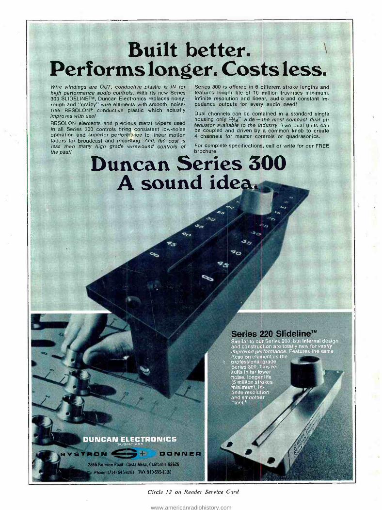
Built better. Performs longer. Costs less. Wire windings are OUT, conductive plastic is IN for high performance audio controls. With its new Series 300 SLIDELINETM, Duncan Electronics replaces noisy. rough and "grainy" wire elements with smooth, noise - free RESOLON' conductive plastic which actually improves with use! RESOLON elements and precious metal wipers used in all Series 300 controls brina consistent low -noise operation and superior perform 1r.e to linear motion faders for broadcast and recoroing. And. the cost is less than many high grade wirewound controls of the past!
Series 300 is offered in 6 different stroke lengths and features longer life of 10 million traverses minimum, infinite resolution and linear, audio and constant im- pedance outputs for every audio need!
Dual channels can be contained in a standard single housing only 13/16" wide - the most compact dual at- tenuator available to the industry. Two dual units can be coupled and driven by a common knob to create 4 channels for master controls or quadrasonics.
For complete specifications, call or write for our FREE brochure.
Duncan Series 300 A sound idea
ernal design and construction are totally new for vastly improved performance. Features the same Resolon element as the professional grade Series 300. This re- sults in far lower noise, longer life (5 million strokes minimum), in- P finite resolution and smoother "feel."
DUNCAN ELECTRON,"
SYSTR Ci 411== ± DONN 2865 Fairview Road Costa Mesa, California 92626
Phone: 1714) 545.261 TWX 910595 -1128
Circle 12 on Reader Service Card
www.americanradiohistory.com
Related Documents