Reading Time: 40 Minutes Price: $2.00 THE MA 6200 INTEGRATED AMPLIFIER

Welcome message from author
This document is posted to help you gain knowledge. Please leave a comment to let me know what you think about it! Share it to your friends and learn new things together.
Transcript
Reading Time: 40 Minutes Price: $2.00
THE MA 6200 INTEGRATED AMPLIFIER

VARIOUS REGULATORY AGENCIES REQUIRE THAT WE BRING THE FOLLOWING INFOR-MATION TO YOUR ATTENTION. PLEASE READ IT CAREFULLY.
WARNING: TO PREVENT FIRE OR SHOCKHAZARD, DO NOT EXPOSE THIS UNIT TORAIN OR MOISTURE.
The Mclntosh you have purchased is a Model MA
6200. It has a serial number located on the rear panel
of the chassis. Record that serial number here:
Serial Number
The model, serial number and purchase date are
important to you for any future service. Record the
purchase date here:
Purchase Date
Upon application, Mclntosh Laboratory provides a
Three-Year Service Contract. Your Mclntosh
authorized Service Agency can expedite repairs
when you provide the Service Contract with the in-
strument for repair. To assist, record your Service
Contract number here:
Service Contract Number

Your MA 6200 Integrated Amplif ierwill give you many years of pleasant andsatisfactory performance. If youhave any questions, please contact:
CUSTOMER SERVICEMclntosh Laboratory Inc.2 Chambers StreetBinghamton, New York 13903-9990Phone: 607-723-3512
Take Advantage of 3 yearsof Contract Service ...Fill in the Application NOW.
ContentsHOW TO INSTALL. . . 2
HOW TO CONNECT... 4THE FRONT PANEL CONTROLS
AND HOW TO USE THEM.. . 8PERFORMANCE LIMITS . . .12
PERFORMANCE CHARTS . . .13,14TECHNICAL DESCRIPTION .. .15
BLOCK DIAGRAM.. .17
MclNTOSH THREE YEAR SERVICE CONTRACTAn application for A THREE YEAR SERVICE CONTRACT is included with this manual.
The terms of the contract are:
1. Mclntosh will provide all parts, materialsand labor needed to return the measuredperformance of the instrument to theoriginal performance limits. The SER-VICE CONTRACT does not cover anyshipping costs to and from the authoriz-ed service agency or the factory.
2. Any Mclntosh authorized service agencywill repair Mclntosh instruments at nor-mal service rates. To receive serviceunder the terms of the SERVICE CON-TRACT, the SERVICE CONTRACT CER-TIFICATE must be presented when theinstrument is taken to the service agency.
3. Always have service done by a Mclntoshauthorized service agency. If the instru-ment is modified or damaged as a resultof unauthorized repair, the SERVICE
CONTRACT will be cancelled. Damageby improper use or mishandling is notcovered by the SERVICE CONTRACT.
4. The SERVICE CONTRACT is issued toyou as the original purchaser. To protectyou from misrepresentation, this con-tract cannot be transferred to a secondowner.
5. To receive the SERVICE CONTRACT,your purchase must be made from aMclntosh franchised dealer.
6. Your completely filled in application forSERVICE CONTRACT must be postmark-ed within 30 days of the date of purchaseof the instrument.
7. To receive the SERVICE CONTRACT, allinformation on the application must befi l led in. The SERVICE CONTRACT wil lbe issued when the completely filled inapplication is received by MclntoshLaboratory Inc. in Binghamton, New York.
Copyright 1979 © by Mclntosh Laboratory Inc. 1

The PANLOC system of install ing equipment con-veniently and securely is a product of Mclntoshresearch. By depressing the two PANLOC buttonson the front panel, the instrument slide can be lock-ed firmly in place or it can be unlocked so that thechassis can slide forward, giving you easy access tothe top and rear panels.
The trouble-free life of an electronic instrument isgreatly extended by providing suff icient venti lationto prevent the buildup of high internal temperaturesthat cause deterioration. Allow enough clearance sothat cool air can enter at the bottom of the cabinetand be vented from the top. With adequate ventila-tion the instrument can be mounted in any position.
The recommended minimum space for installationis 15 inches (38.1 cm) deep, 17 inches (43.2 cm) wide,and 6 inches (15.2 cm) high.
To install the instrument in a Mclntosh cabinet,follow the instructions that are enclosed with thecabinet. For any other type of installation followthese instructions:1. Open the carton and remove the PANLOCbrackets, hardware package, and mountingtemplate from the carton. Remove the MA 6200 fromits plastic bag and place it upside down on the ship-ping pallet; unscrew the four plastic feet from thebottom of the chassis.2. Mark the cabinet panel.Place the mounting template in the position on thecabinet panel where the instrument is to be install-ed, and tape it in place. The broken lines that repre-sent the outline of the rectangular cutout also repre-sent the outside dimensions of the chassis. Makesure these lines clear shelves, partitions, or anyequipment. With the template in place, first mark thesix A and B holes and the four small holes thatlocate the corners of the cutout. Then, join the fourcorner markings with pencil lines, using the edge ofthe template as a straightedge.3. Drill HolesUse a drill with a 3/16 inch bit held perpendicular tothe panel and drill the six A and B holes. Then, usinga dri l l bit slightly wider than the tip of your sawblade, dri l l one hole at each of two diagonally op-posite corners. The holes should barely touch the in-side edge of the penciled outline. Before taking thenext step, make sure that the six A and B holes havebeen drilled.4. Saw the Panel CutoutSaw carefully on the inside of the penciled lines.First make the two long cuts and then the two shortcuts. After the rectangular opening has been cut out,use a file to square the corners and smooth any ir-regularities in the cut edges.
2
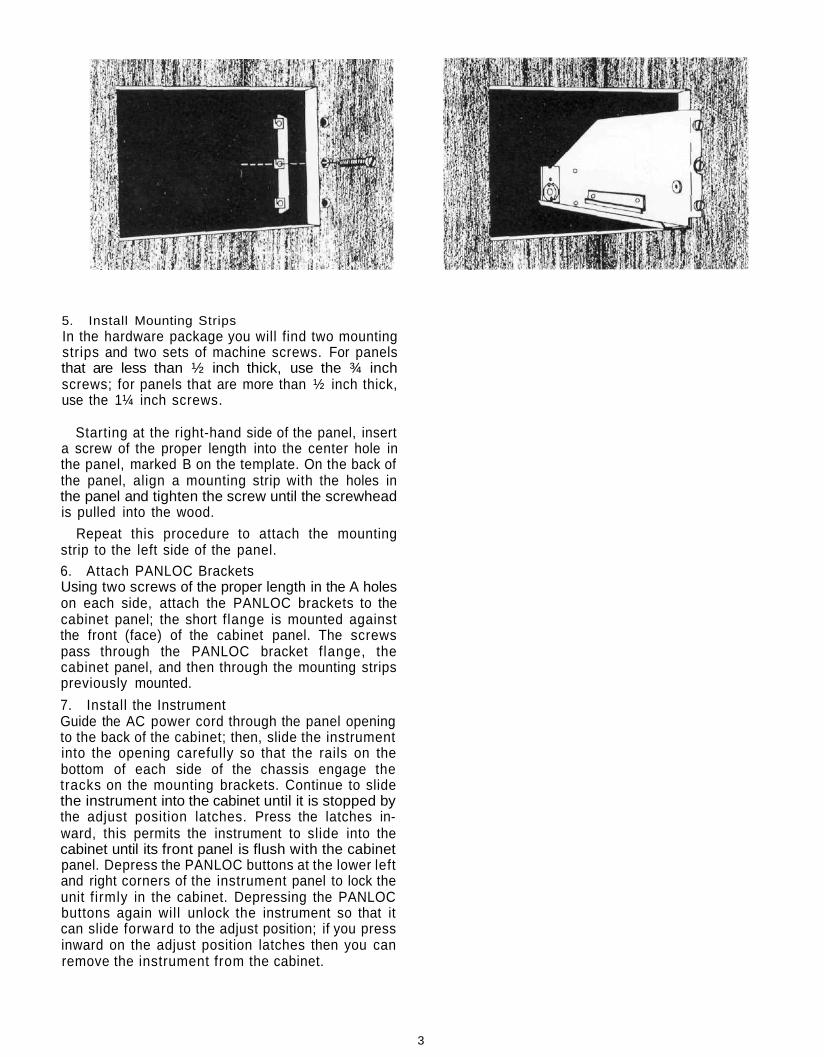
5. Install Mounting StripsIn the hardware package you will find two mountingstrips and two sets of machine screws. For panelsthat are less than ½ inch thick, use the ¾ inchscrews; for panels that are more than ½ inch thick,use the 1¼ inch screws.
Starting at the right-hand side of the panel, inserta screw of the proper length into the center hole inthe panel, marked B on the template. On the back ofthe panel, align a mounting strip with the holes inthe panel and tighten the screw until the screwheadis pulled into the wood.
Repeat this procedure to attach the mountingstrip to the left side of the panel.6. Attach PANLOC BracketsUsing two screws of the proper length in the A holeson each side, attach the PANLOC brackets to thecabinet panel; the short flange is mounted againstthe front (face) of the cabinet panel. The screwspass through the PANLOC bracket f lange, thecabinet panel, and then through the mounting stripspreviously mounted.
7. Install the InstrumentGuide the AC power cord through the panel openingto the back of the cabinet; then, slide the instrumentinto the opening carefully so that the rails on thebottom of each side of the chassis engage thetracks on the mounting brackets. Continue to slidethe instrument into the cabinet until it is stopped bythe adjust position latches. Press the latches in-ward, this permits the instrument to slide into thecabinet until its front panel is flush with the cabinetpanel. Depress the PANLOC buttons at the lower leftand right corners of the instrument panel to lock theunit f irmly in the cabinet. Depressing the PANLOCbuttons again will unlock the instrument so that itcan slide forward to the adjust position; if you pressinward on the adjust position latches then you canremove the instrument from the cabinet.
3

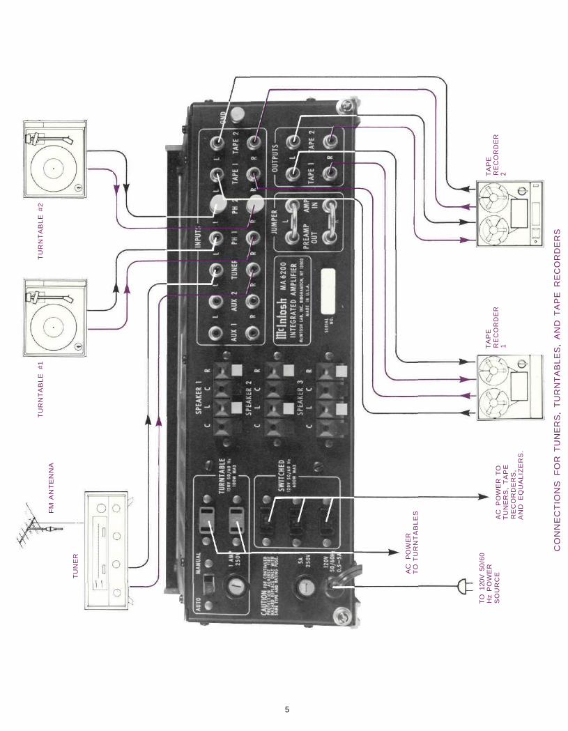
How to Connect
CONNECTING TURNTABLE TO PHONO 1 AND 2Connect the cable from the "left" channel of the
turntable into the L PHONO 1 INPUT jack. Connectthe "right" channel into the R PHONO 1 INPUT jack.
Connect a second turntable in the same mannerto the PHONO 2 INPUT jacks. Shorting plugs areshipped in the PHONO 2 INPUT jacks to eliminatenoise if a second turntable is not used. Removethese shorting plugs when connecting the secondturntable. Keep them for possible future use. DONOT plug the shorting plugs into an output jack asthis may prevent operation of the MA 6200.
GROUND CONNECTIONA single ground post is provided. Grounds for turn-
tables, record changers, tape decks, etc. are to beconnected to this post. The left and right programcables and the ground wire from that source shouldbe wound or twisted together. To avoid hum makesure the ground wire does not make any connec-tions to the shields of the left and right programcables between the program source and the MA6200.
CONNECTING A STEREO TUNER AND AUX 1 AND 2Connect the cable from the "left" channel tuner
output to the L TUNER INPUT jack.
Connect the cable from the "right" channel tuneroutput to the R TUNER INPUT jack
AUX—Any high level program source such as atuner, a TV set or a tape recorder can be connectedto the AUX 1 and 2 INPUT jacks. The connecting pro-cedure is the same as for the tuner input.
CONNECTING TAPE RECORDERSTo Record:
Connect a cable from the L TAPE 1 OUTPUT jackto the left high level input of the tape recorder. Con-nect a cable from the R TAPE 1 OUTPUT jack to theright high level input of the tape recorder.
Connect a second recorder in the same manner tothe TAPE 2 OUTPUT jacks.
To Playback/Monitor:Connect a cable from the left channel output of a
tape recorder to the L TAPE 1 INPUT jack. Connect acable from the right channel output of a taperecorder to the R TAPE 1 INPUT jack.
Connect a second recorder in the same manner tothe TAPE 2 INPUT jacks.
CONNECTING AC POWERThe MA 6200 AC power cord is to be plugged into
a 120 volt 50/60 Hz wall outlet.
There are two types of AC power outlets on theback panel of the MA 6200; three black, and twogreen.
The green AC power outlets are on at all times.Plug the AC power cables from the turntable into thegreen TURNTABLE power outlets on the rear panel.
The three black outlets are switched on and offwhen the amplifier is turned on or off. These are in-tended for equalizers and other accessories.
The POWER ON pushbutton shares AC powercontrol, with the AC power switch on a turntable,through a current detecting switch circuit. On therear panel the TURNTABLE AUTO/MANUAL switchselects the mode of operation.
When the switch is in the AUTO position and aturntable plugged into one of the green AC poweroutlets, the AC power to the receiver and to theblack AC power outlets can be controlled by the
4
5
TO
12
0V 5
0/6
0H
z P
OW
ER
SO
UR
CEA
C
PO
WE
RT
O T
UR
NT
AB
LE
S
CO
NN
EC
TIO
NS
F
OR
TU
NE
RS
, T
UR
NT
AB
LE
S,
AN
D T
AP
E
RE
CO
RD
ER
S
TA
PE
RE
CO
RD
ER
1A
C
PO
WE
R T
OT
UN
ER
S,
TA
PE
RE
CO
RD
ER
S,
AN
D
EQ
UA
LIZ
ER
S.
TA
PE
RE
CO
RD
ER
2
TU
RN
TA
BL
E #
2T
UR
NT
AB
LE
#
1
FM
AN
TE
NN
A
TU
NE
R

turntable on/off switch. When AC power to the turn-table is turned on, automatically the instrument andthe SWITCHED black AC power outlets are turnedon. The system will remain on until the turntable isturned off. The POWER ON pushbutton controls theAC power for any source other than the turntable.
In the MANUAL position only the POWER ONpushbutton will turn AC power on or off.
Some turntables have electronic circuits thatdraw current all the time. To use these turntables theAUTO/MANUAL switch must be in the MANUALposition. With the AUTO/MANUAL switch in theMANUAL position, AC power to the system will becontrolled by the front panel POWER pushbutton only.
FUSESA 5-amp fuse protects the MA 6200 circuits. The
fuse does not protect additional equipment con-nected to the rear panel AC power outlets. A oneamp fuse protects the turntable auto on circuit. Ifthis fuse fails, power to the green outlets will be in-terrupted.
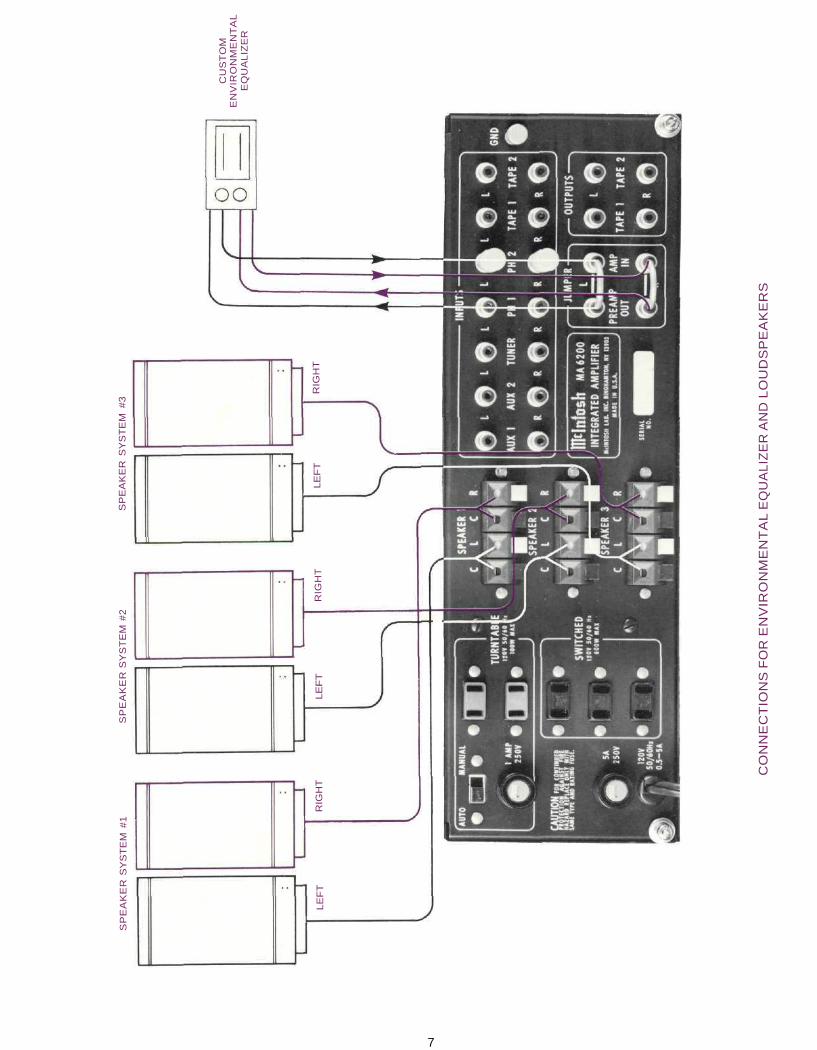
CONNECTING LOUDSPEAKERS FOR STEREOAll speakers are connected to the push connec-
tors on the rear panel. When stereo speakers havebeen connected to the proper push connectors, thecorresponding front panel pushbuttons turn thespeakers on or off.
Selection of the proper gauge wire to connect theloudspeakers preserves the quality of sound repro-duction for which the loudspeakers have been de-signed. If undersize wire is used, resistance is addedto the amplifier/loudspeaker combination whichadversely affects the performance. Added resis-tance causes reduction of damping characteristics,modification of frequency response and reduction inpower output.
Use lamp cord, bell wire, or wire with similar typeof insulation to connect the speakers to the am-plifier. In all cases, the leads to and from the speakershould be twin conductor or twisted together. Whenusing 8 ohm speakers and for the normally shortdistances of under 30 feet between the amplifier andspeaker, No. 18 wire or larger can be used. Fordistances over 30 feet between the amplifier andspeaker use larger diameter wire. Select the correctsize wire for the wire length from the chart. It isrecommended that the DC resistance of the speakerleads be less than 5% of the speaker impedance. Upto 10% can be tolerated. Resistance of the leadsshould be computed for the length of wire both toand from the speaker or speakers.
For multiple speaker operation, run separateleads from the amplifier to the speakers.
CONNECTING ONE LOUDSPEAKER FOR MONOThe left and right outputs of the MAC 6200 must con-nect to separate loudspeakers. Do not parallel theoutput connections for a single loudspeaker. If theleft and right outputs are connected together ex-cessive heat is generated in the power amplifierswhich causes damage even though the MODESELECTOR pushbutton is in the MONO position. Ifyou wish to drive a single loudspeaker, put theMODE SELECTOR in MONO and connect the loud-speaker to the left or the right speaker push connec-tors only. It is not necessary to connect a load to theother channel output.
CONNECTING A MclNTOSH EQUALIZEROn the JUMPER panel, remove the jumpers bet-
ween the PREAMP OUT jacks and power AMP INputjacks. The environmental equalizer is connected bet-ween these jacks. Use standard shielded cables.Connect the PREAMP OUT to the input of theequalizer. Connect the output of the equalizer to thepower AMP INput jack.
MAXIMUM WIRE LENGTHSWire
Gauge22201816141210
For 4 Ohm Load
Feet6
1015254060
100
Meters1.83.14.67.6
12.218.330.5
For 8 Ohm Load
Feet1220305080
120200
Meters3.76.19.1
15.224.436.666.0
Wire lengths above represent the wire resistance equal to 5%of the speaker impedance.
6
Connect the leads from the left main loudspeakerto the SPEAKER 1 Left and Common push connec-tors. Connect the lead from the right mainloudspeaker to the SPEAKER 1 Right and Commonpush connectors. Connect the leads from a secondleft loudspeaker to the SPEAKER 2 Left and Com-mon push connectors. Connect the lead from a se-cond right loudspeaker to the SPEAKER 2 Right andCommon push connectors. Connect the leads froma third left loudspeaker to the SPEAKER 3 Left andCommon push connectors. Connect the lead from athird right loudspeaker to the SPEAKER 3 Right andCommon push connectors.
The push connector on the MA 6200 will accept upto 16 gauge wire. When larger wire is used it will benecessary to splice a short length of 16 gauge wireto the ends of the heavier wire to make connections.A similar arrangement may be required to connect atthe speakers.
SP
EA
KE
R S
YS
TE
M #
1
LE
FT
RIG
HT
LE
FT
SP
EA
KE
R S
YS
TE
M #
2
RIG
HT
LE
FT
SP
EA
KE
R S
YS
TE
M #
3
RIG
HT
CU
ST
OM
EN
VIR
ON
ME
NT
AL
EQ
UA
LIZ
ER
CO
NN
EC
TIO
NS
FO
R E
NV
IRO
NM
EN
TA
L E
QU
AL
IZE
R A
ND
LO
UD
SP
EA
KE
RS
7
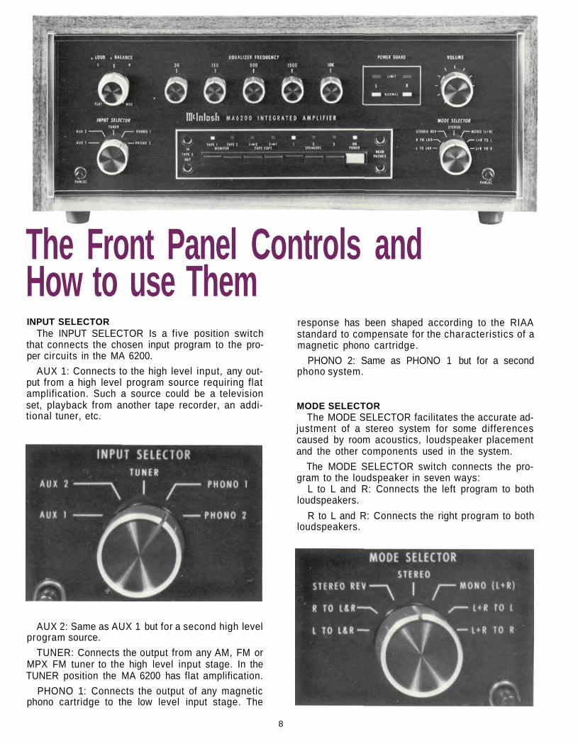
The Front Panel Controls andHow to use ThemINPUT SELECTOR
The INPUT SELECTOR Is a five position switchthat connects the chosen input program to the pro-per circuits in the MA 6200.
AUX 1: Connects to the high level input, any out-put from a high level program source requiring flatamplification. Such a source could be a televisionset, playback from another tape recorder, an addi-tional tuner, etc.
response has been shaped according to the RIAAstandard to compensate for the characteristics of amagnetic phono cartridge.
PHONO 2: Same as PHONO 1 but for a secondphono system.
MODE SELECTORThe MODE SELECTOR facilitates the accurate ad-
justment of a stereo system for some differencescaused by room acoustics, loudspeaker placementand the other components used in the system.
The MODE SELECTOR switch connects the pro-gram to the loudspeaker in seven ways:
L to L and R: Connects the left program to bothloudspeakers.
R to L and R: Connects the right program to bothloudspeakers.
AUX 2: Same as AUX 1 but for a second high levelprogram source.
TUNER: Connects the output from any AM, FM orMPX FM tuner to the high level input stage. In theTUNER position the MA 6200 has flat amplification.
PHONO 1: Connects the output of any magneticphono cartridge to the low level input stage. The
8
STEREO REV: Connects the left program to theright loudspeaker and the right program to the leftloudspeaker.
STEREO: Connects the left program to the leftloudspeaker and the right program to the rightloudspeaker.
MONO (L + R): Adds the left and right programstogether and connects to both loudspeakers.
L + R to L: Connects the left plus right program tothe left loudspeaker only.
L + R to R: Connects the left plus right program tothe right loudspeaker only.
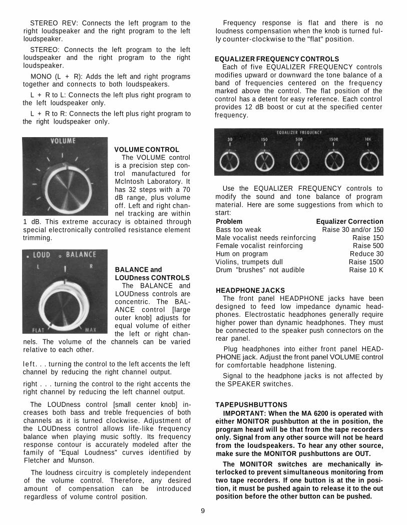
VOLUME CONTROLThe VOLUME control
is a precision step con-trol manufactured forMclntosh Laboratory. Ithas 32 steps with a 70dB range, plus volumeoff. Left and right chan-nel tracking are within
1 dB. This extreme accuracy is obtained throughspecial electronically controlled resistance elementtrimming.
BALANCE andLOUDness CONTROLS
The BALANCE andLOUDness controls areconcentric. The BAL-ANCE control [largeouter knob] adjusts forequal volume of eitherthe left or right chan-
nels. The volume of the channels can be variedrelative to each other.
l e f t . . . turning the control to the left accents the leftchannel by reducing the right channel output.
right . . . turning the control to the right accents theright channel by reducing the left channel output.
The LOUDness control [small center knob] in-creases both bass and treble frequencies of bothchannels as it is turned clockwise. Adjustment ofthe LOUDness control allows l i fe- l ike frequencybalance when playing music softly. Its frequencyresponse contour is accurately modeled after thefamily of "Equal Loudness" curves identified byFletcher and Munson.
The loudness circuitry is completely independentof the volume control. Therefore, any desiredamount of compensation can be introducedregardless of volume control position.
Frequency response is flat and there is noloudness compensation when the knob is turned ful-ly counter-clockwise to the "flat" position.
EQUALIZER FREQUENCY CONTROLSEach of f ive EQUALIZER FREQUENCY controls
modifies upward or downward the tone balance of aband of frequencies centered on the frequencymarked above the control. The flat position of thecontrol has a detent for easy reference. Each controlprovides 12 dB boost or cut at the specified centerfrequency.
Use the EQUALIZER FREQUENCY controls tomodify the sound and tone balance of programmaterial. Here are some suggestions from which tostart:Problem Equalizer CorrectionBass too weak Raise 30 and/or 150Male vocalist needs reinforcing Raise 150Female vocalist reinforcing Raise 500Hum on program Reduce 30Violins, trumpets dull Raise 1500Drum "brushes" not audible Raise 10 K
HEADPHONE JACKSThe front panel HEADPHONE jacks have been
designed to feed low impedance dynamic head-phones. Electrostatic headphones generally requirehigher power than dynamic headphones. They mustbe connected to the speaker push connectors on therear panel.
Plug headphones into either front panel HEAD-PHONE jack. Adjust the front panel VOLUME controlfor comfortable headphone listening.
Signal to the headphone jacks is not affected bythe SPEAKER switches.
TAPE PUSHBUTTONSIMPORTANT: When the MA 6200 is operated with
either MONITOR pushbutton at the in position, theprogram heard will be that from the tape recordersonly. Signal from any other source will not be heardfrom the loudspeakers. To hear any other source,make sure the MONITOR pushbuttons are OUT.
The MONITOR switches are mechanically in-terlocked to prevent simultaneous monitoring fromtwo tape recorders. If one button is at the in posi-tion, it must be pushed again to release it to the outposition before the other button can be pushed.
9
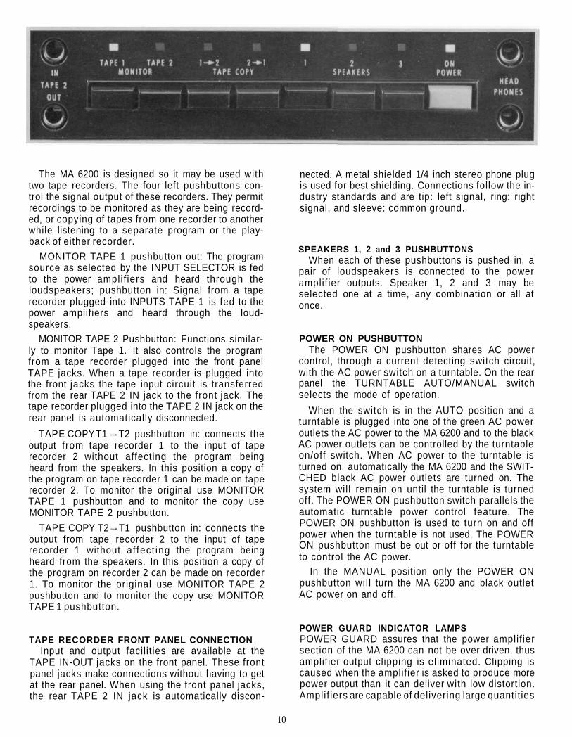
The MA 6200 is designed so it may be used withtwo tape recorders. The four left pushbuttons con-trol the signal output of these recorders. They permitrecordings to be monitored as they are being record-ed, or copying of tapes from one recorder to anotherwhile listening to a separate program or the play-back of either recorder.
MONITOR TAPE 1 pushbutton out: The programsource as selected by the INPUT SELECTOR is fedto the power ampli f iers and heard through theloudspeakers; pushbutton in: Signal from a taperecorder plugged into INPUTS TAPE 1 is fed to thepower amplifiers and heard through the loud-speakers.
MONITOR TAPE 2 Pushbutton: Functions similar-ly to monitor Tape 1. It also controls the programfrom a tape recorder plugged into the front panelTAPE jacks. When a tape recorder is plugged intothe front jacks the tape input circuit is transferredfrom the rear TAPE 2 IN jack to the front jack. Thetape recorder plugged into the TAPE 2 IN jack on therear panel is automatically disconnected.
TAPE COPY T1 T2 pushbutton in: connects theoutput from tape recorder 1 to the input of taperecorder 2 without affecting the program beingheard from the speakers. In this position a copy ofthe program on tape recorder 1 can be made on taperecorder 2. To monitor the original use MONITORTAPE 1 pushbutton and to monitor the copy useMONITOR TAPE 2 pushbutton.
TAPE COPY T2 T1 pushbutton in: connects theoutput from tape recorder 2 to the input of taperecorder 1 without af fect ing the program beingheard from the speakers. In this position a copy ofthe program on recorder 2 can be made on recorder1. To monitor the original use MONITOR TAPE 2pushbutton and to monitor the copy use MONITORTAPE 1 pushbutton.
TAPE RECORDER FRONT PANEL CONNECTIONInput and output facil it ies are available at the
TAPE IN-OUT jacks on the front panel. These frontpanel jacks make connections without having to getat the rear panel. When using the front panel jacks,the rear TAPE 2 IN jack is automatically discon-
nected. A metal shielded 1/4 inch stereo phone plugis used for best shielding. Connections follow the in-dustry standards and are tip: left signal, ring: rightsignal, and sleeve: common ground.
SPEAKERS 1, 2 and 3 PUSHBUTTONSWhen each of these pushbuttons is pushed in, a
pair of loudspeakers is connected to the poweramplif ier outputs. Speaker 1, 2 and 3 may beselected one at a time, any combination or all atonce.
POWER ON PUSHBUTTONThe POWER ON pushbutton shares AC power
control, through a current detecting switch circuit,with the AC power switch on a turntable. On the rearpanel the TURNTABLE AUTO/MANUAL switchselects the mode of operation.
When the switch is in the AUTO position and aturntable is plugged into one of the green AC poweroutlets the AC power to the MA 6200 and to the blackAC power outlets can be controlled by the turntableon/off switch. When AC power to the turntable isturned on, automatically the MA 6200 and the SWIT-CHED black AC power outlets are turned on. Thesystem wil l remain on until the turntable is turnedoff. The POWER ON pushbutton switch parallels theautomatic turntable power control feature. ThePOWER ON pushbutton is used to turn on and offpower when the turntable is not used. The POWERON pushbutton must be out or off for the turntableto control the AC power.
In the MANUAL position only the POWER ONpushbutton wil l turn the MA 6200 and black outletAC power on and off.
POWER GUARD INDICATOR LAMPSPOWER GUARD assures that the power amplif iersection of the MA 6200 can not be over driven, thusamplifier output clipping is eliminated. Clipping iscaused when the amplifier is asked to produce morepower output than it can deliver with low distortion.Amplif iers are capable of delivering large quantit ies
10
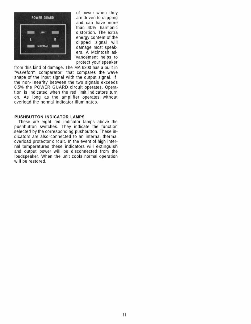
of power when theyare driven to clippingand can have morethan 40% harmonicdistortion. The extraenergy content of theclipped signal willdamage most speak-ers. A Mclntosh ad-vancement helps toprotect your speaker
from this kind of damage. The MA 6200 has a built in"waveform comparator" that compares the waveshape of the input signal with the output signal. Ifthe non-linearity between the two signals exceeds0.5% the POWER GUARD circuit operates. Opera-tion is indicated when the red limit indicators turnon. As long as the amplifier operates withoutoverload the normal indicator il luminates.
PUSHBUTTON INDICATOR LAMPSThese are eight red indicator lamps above the
pushbutton switches. They indicate the functionselected by the corresponding pushbutton. These in-dicators are also connected to an internal thermaloverload protector circuit. In the event of high inter-nal temperatures these indicators will extinguishand output power will be disconnected from theloudspeaker. When the unit cools normal operationwil l be restored.
11
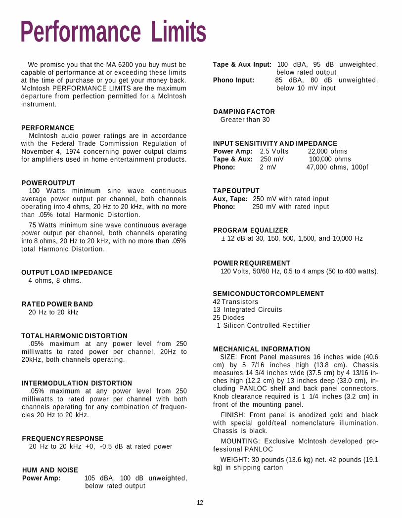
Performance LimitsWe promise you that the MA 6200 you buy must be
capable of performance at or exceeding these l imitsat the time of purchase or you get your money back.Mclntosh PERFORMANCE LIMITS are the maximumdeparture from perfection permitted for a Mclntoshinstrument.
PERFORMANCEMclntosh audio power ratings are in accordance
with the Federal Trade Commission Regulation ofNovember 4, 1974 concerning power output claimsfor amplifiers used in home entertainment products.
POWER OUTPUT100 Watts minimum sine wave continuous
average power output per channel, both channelsoperating into 4 ohms, 20 Hz to 20 kHz, with no morethan .05% total Harmonic Distortion.
75 Watts minimum sine wave continuous averagepower output per channel, both channels operatinginto 8 ohms, 20 Hz to 20 kHz, with no more than .05%total Harmonic Distortion.
OUTPUT LOAD IMPEDANCE4 ohms, 8 ohms.
RATED POWER BAND20 Hz to 20 kHz
TOTAL HARMONIC DISTORTION.05% maximum at any power level from 250
milliwatts to rated power per channel, 20Hz to20kHz, both channels operating.
INTERMODULATION DISTORTION.05% maximum at any power level from 250
mill iwatts to rated power per channel with bothchannels operating for any combination of frequen-cies 20 Hz to 20 kHz.
FREQUENCY RESPONSE20 Hz to 20 kHz +0, -0.5 dB at rated power
HUM AND NOISEPower Amp: 105 dBA, 100 dB unweighted,
below rated output
Tape & Aux Input: 100 dBA, 95 dB unweighted,below rated output
Phono Input: 85 dBA, 80 dB unweighted,below 10 mV input
DAMPING FACTORGreater than 30
INPUT SENSITIVITY AND IMPEDANCEPower Amp: 2.5 Volts 22,000 ohmsTape & Aux: 250 mV 100,000 ohmsPhono: 2 mV 47,000 ohms, 100pf
TAPE OUTPUTAux, Tape: 250 mV with rated inputPhono: 250 mV with rated input
PROGRAM EQUALIZER± 12 dB at 30, 150, 500, 1,500, and 10,000 Hz
POWER REQUIREMENT120 Volts, 50/60 Hz, 0.5 to 4 amps (50 to 400 watts).
SEMICONDUCTOR COMPLEMENT42 Transistors13 Integrated Circuits25 Diodes
1 Silicon Controlled Rectif ier
MECHANICAL INFORMATIONSIZE: Front Panel measures 16 inches wide (40.6
cm) by 5 7/16 inches high (13.8 cm). Chassismeasures 14 3/4 inches wide (37.5 cm) by 4 13/16 in-ches high (12.2 cm) by 13 inches deep (33.0 cm), in-cluding PANLOC shelf and back panel connectors.Knob clearance required is 1 1/4 inches (3.2 cm) infront of the mounting panel.
FINISH: Front panel is anodized gold and blackwith special gold/teal nomenclature illumination.Chassis is black.
MOUNTING: Exclusive Mclntosh developed pro-fessional PANLOC
WEIGHT: 30 pounds (13.6 kg) net. 42 pounds (19.1kg) in shipping carton
12
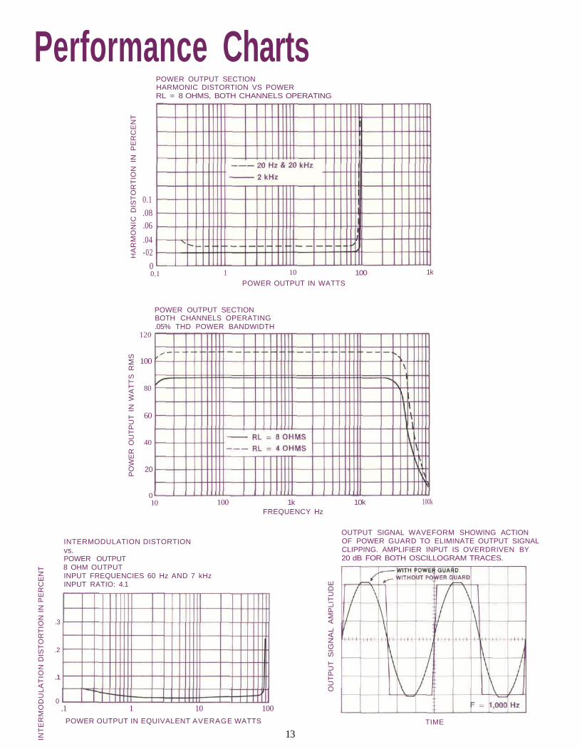
Performance ChartsPOWER OUTPUT SECTIONHARMONIC DISTORTION VS POWERRL = 8 OHMS, BOTH CHANNELS OPERATING
POWER OUTPUT IN WATTS
100 1k
POWER OUTPUT SECTIONBOTH CHANNELS OPERATING.05% THD POWER BANDWIDTH
10 100 1kFREQUENCY Hz
10k 100k
INTERMODULATION DISTORTIONvs.POWER OUTPUT8 OHM OUTPUTINPUT FREQUENCIES 60 Hz AND 7 kHzINPUT RATIO: 4.1
OUTPUT SIGNAL WAVEFORM SHOWING ACTIONOF POWER GUARD TO ELIMINATE OUTPUT SIGNALCLIPPING. AMPLIFIER INPUT IS OVERDRIVEN BY20 dB FOR BOTH OSCILLOGRAM TRACES.
POWER OUTPUT IN EQUIVALENT AVERAGE WATTS TIME
13
0.1
.08
.06
.04-02
00.1 1 10
HA
RM
ON
IC D
IST
OR
TIO
N I
N P
ER
CE
NT
120
100
80
60
40
20
0
PO
WE
R O
UT
PU
T I
N W
AT
TS
RM
S
INT
ER
MO
DU
LA
TIO
N D
IST
OR
TIO
N I
N P
ER
CE
NT
.3
.2
.1
0.1 1 10 100
OU
TP
UT
SIG
NA
L A
MP
LIT
UD
E
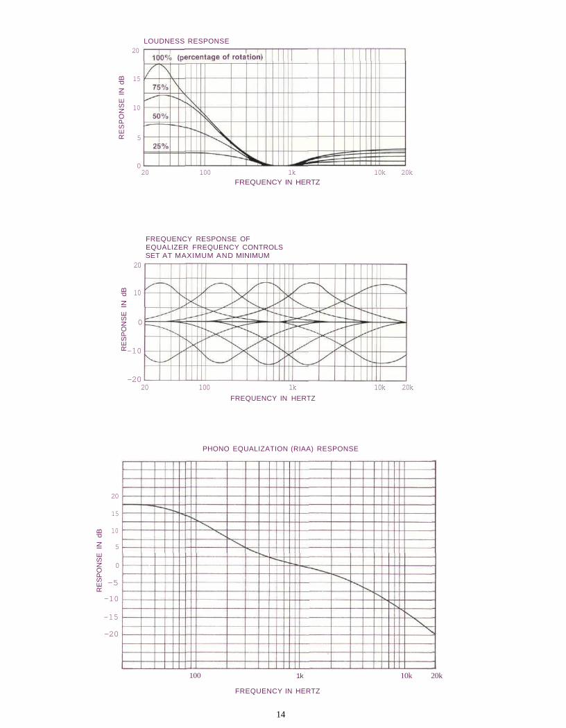
LOUDNESS RESPONSE
20 100 1k 10k 20k
FREQUENCY IN HERTZ
FREQUENCY RESPONSE OFEQUALIZER FREQUENCY CONTROLSSET AT MAXIMUM AND MINIMUM
20
15
10
5
0
-5
-10
-15
-20
20 100 1k 10k 20k
FREQUENCY IN HERTZ
PHONO EQUALIZATION (RIAA) RESPONSE
100 1k
FREQUENCY IN HERTZ
10k 20k
14
20
15
10
5
0
RE
SP
ON
SE
IN
dB
20
10
0
-10
-20
RE
SP
ON
SE
IN
dB
RE
SP
ON
SE
IN
dB
Technical DescriptionAUDIO SECTION
Each channel of the MA 6200 has four basic sec-tions. They are: phono preamplifier, high level andloudness amplifier, equalizer amplifier, and poweramplifier.
PHONO PREAMPLIFIERThe phono preamplifier uses a high technology in-
tegrated circuit operational amplifier. Its differentialinput stage has been optimized for low noise andlow distortion performance. Open loop gain of thisintegrated circuit is 100,000. With high open loopgain a large amount of negative feedback can be us-ed around the phono preamplifier to further reducenoise and distortion. The feedback network also pro-vides precision RIAA frequency compensation. Thenetwork uses 1% metal f i lm resistors and 5% polyfilm capacitors. To achieve low noise performance itis essential that the feedback network be very lowimpedance. As a consequence, the preamplifiermust be capable of operating as a power amplifier todrive this impedance. The actual power outputcapability of this preamplifier stage is more than 100mil l iwatts, a great margin beyond that which is re-quired.
Input sensitivity of the phono preamplifier is 2millivolts. The gain of the amplifier is 42 dB at 1000Hz. The phono preamplifier has a very wide dynamicrange. At 1000 Hz the phono input circuit will accept100 millivolts without overload, a voltage far greaterthan the output of any current magnetic phono car-tridge. Phono input overload therefore is virtually im-possible. A signal level of 10 millivolts at the phonoinput at 1000 Hz will produce 1.2 volts at the tapeoutput. The tape output has a source impedance of200 ohms. For most efficient signal transfer the tapeoutput should operate into a load impedance of5,000 ohms or greater.
HIGH LEVEL AMPLIFIERAt the input to the high level or loudness amplifier
the signal passes through the mode switch, thenthrough the volume control, and into the amplifier. Inthe past loudness controls have typically used sim-ple passive circuits connected to a tap on thevolume control. As a consequence, compensationaccuracy was dependent on many variables such asvolume control position and differences in inputlevel. The MA 6200 uses active circuitry. The sametype of integrated circuit operational amplifier thatis used in the phono amplifier is used here. It hastwo feedback loops. One feedback loop is f lat. Theother feedback loop conforms to the Fletcher-
Munson equal loudness compensation. A poten-tiometer is placed between these two feedbackloops making it possible to select any combinationof the two from a flat response to full loudness com-pensation. The overall gain of the stage is 20 dB andis not affected by the position of the loudness con-trol at mid frequencies.
EQUALIZER AMPLIFIERThe equalizer amplifier is constructed with the
same operational amplif iers as used in previousamplifiers. Five other operational amplifiers areeach arranged in an active circuit configuration thatis the equivalent of a series tuned circuit, one ateach of the five center frequencies. Each series tun-ed circuit is inserted, via the equalizer control poten-tiometer, in either the input circuit or feedback cir-cuit of the equalizer amplif ier thereby providing aboost and cut capability of 12 dB for each band offrequencies.
POWER AMPLIFIERThe input impedance of the power amplifier is
22,000 ohms and requires 2.5 volts rms to drive theamplif ier to rated output. The short jumpers on therear panel of the MA 6200 connect the equalizeramplif ier output [PREAMP OUT] and power amplifierinput [AMP IN]. At the input of the power amplifiertwo transistors are connected as a differentialamplifier. The two input signals to the differentialamplif ier are the input signal and the negative feed-back signal from the power amplifier. The differen-tia! amplifier permits the best use of negative feed-back to maintain low noise and low distortion perfor-mance. The outputs of the differential amplifier arecombined in a current mirror to a single output. Thecurrent mirror feeds a linear voltage amplifier whichin turn drives two medium power driver transistors.The drive transistors feed the output stages. Theoutput section is arranged as a fully complementarydirect coupled series push/pull amplifier. The powertransistors used in the output circuit are selected fortheir high power dissipation capability, wide fre-quency response, and large safe operating area. Thepower transistors are mounted on large blackanodized heat sinks to assure that under normaloperating conditions the transistors will operate at alow temperature. If operating temperatures shouldincrease due to a shorted speaker or restricted ven-tilation, an automatic sensing device turns thespeaker circuit off. The speaker circuit will turn onagain when the temperature has returned to its nor-mal limits. This additional protection assures you ofrel iabil i ty even under the most extreme operating
15
conditions. To further insure reliability a specialpower output SENTRY MONITORING CIRCUITprevents failure of the power amplifier transistorsdue to excessive mismatch or shorting of the output.When the MA 6200 operates normally the SENTRYMONITORING CIRCUIT has no ef fect on signalspassing through the power amplifier. If the powerdissipation in the output transistors should riseabove normal design limits the SENTRY MONITOR-ING CIRCUIT restricts the drive to the output stagewhich reduces the dissipation in the output tran-sistors. The SENTRY MONITORING CIRCUIT acts in-stantaneously for any input signal or load combina-tion. This arrangement assures circuit reliability. On-ly Mclntosh gives you this degree of protection.
The direct coupled complementary amplifier cir-cuit holds the output at DC ground potential whenthere is no signal input which eliminates the needfor a coupling capacitor in the output. The MA 6200power amplifier is all direct coupled to insure max-imum low frequency performance. In most directcoupled circuits, failure of any transistor in thepower amplifier will cause a DC potential to appearin the output. To assure that no damaging or interfer-ing DC appears across the output terminals, aspecial, very fast acting protector circuit constantlymonitors the output circuit for DC. If, at any time, aconstant DC level appears, the speakers are discon-nected. The protective circuit reacts in milliseconds.Speakers remain disconnected unti l the cause hasbeen fixed. Under normal operating conditions theprotective circuit has no af fect on the operation ofthe output circuit. This is another example of Mcln-tosh continuous protection.
occurs when an amplifier is asked to exceed itsdesign limits and the capacity of the power supply.Since POWER GUARD does not begin to work untilthis point is reached, the power capability of theamplifier is never affected.
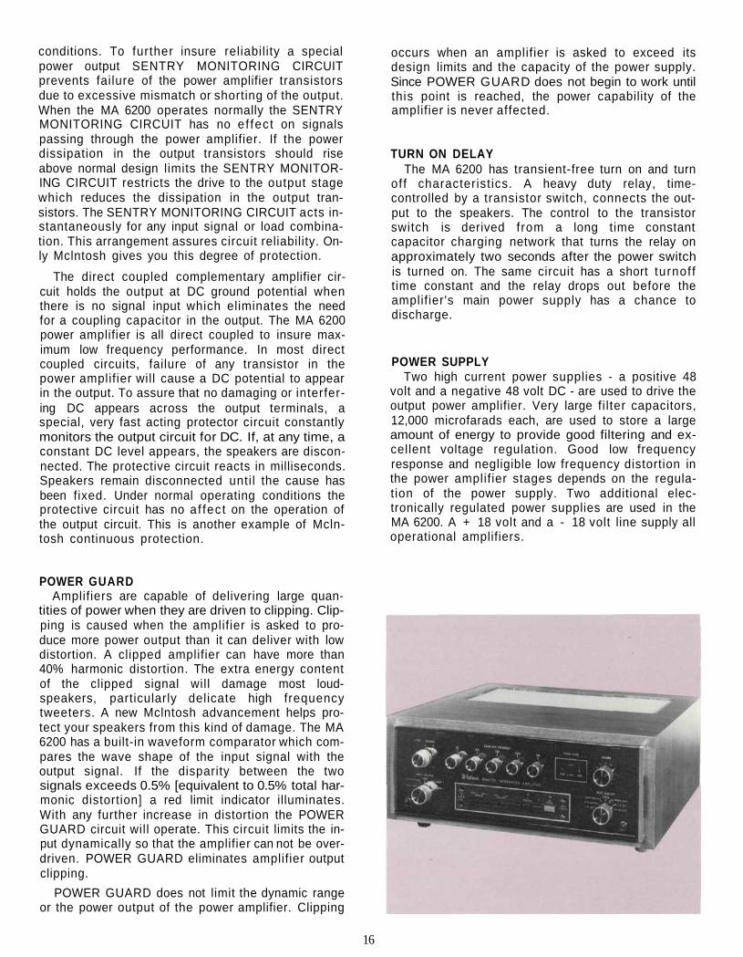
TURN ON DELAYThe MA 6200 has transient-free turn on and turn
off characteristics. A heavy duty relay, time-controlled by a transistor switch, connects the out-put to the speakers. The control to the transistorswitch is derived from a long time constantcapacitor charging network that turns the relay onapproximately two seconds after the power switchis turned on. The same circuit has a short turnofftime constant and the relay drops out before theamplifier's main power supply has a chance todischarge.
POWER SUPPLYTwo high current power supplies - a positive 48
volt and a negative 48 volt DC - are used to drive theoutput power amplifier. Very large fi l ter capacitors,12,000 microfarads each, are used to store a largeamount of energy to provide good filtering and ex-cellent voltage regulation. Good low frequencyresponse and negligible low frequency distortion inthe power amplif ier stages depends on the regula-tion of the power supply. Two additional elec-tronically regulated power supplies are used in theMA 6200. A + 18 volt and a - 18 volt line supply alloperational amplifiers.
POWER GUARDAmplifiers are capable of delivering large quan-
tities of power when they are driven to clipping. Clip-ping is caused when the amplifier is asked to pro-duce more power output than it can deliver with lowdistortion. A clipped amplifier can have more than40% harmonic distortion. The extra energy contentof the clipped signal will damage most loud-speakers, particularly delicate high frequencytweeters. A new Mclntosh advancement helps pro-tect your speakers from this kind of damage. The MA6200 has a built-in waveform comparator which com-pares the wave shape of the input signal with theoutput signal. If the disparity between the twosignals exceeds 0.5% [equivalent to 0.5% total har-monic distortion] a red limit indicator illuminates.With any further increase in distortion the POWERGUARD circuit will operate. This circuit limits the in-put dynamically so that the amplifier can not be over-driven. POWER GUARD eliminates amplifier outputclipping.
POWER GUARD does not limit the dynamic rangeor the power output of the power amplifier. Clipping
16
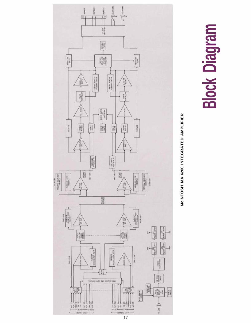
Block
Diag
ram
Mcl
NT
OS
H M
A 6
200
INT
EG
RA
TE
D A
MP
LIF
IER
17

MclNTOSH LABORATORY INC.2 CHAMBERS ST., BINGHAMTON, N.Y. 13903-2699
607-723-3512The continuous improvement of its products is the policy ofMclntosh Laboratory Incorporated who reserve the right to
improve design without notice.Printed in U.S.A.
039179BE032003
Related Documents