8 The Invesgaon of...(Sukamta, Aldi Rahadian Ilham, Sudarja) THE INVESTIGATION OF VOID FRACTION OF TWO-PHASE FLOW AIR-WATER AND GLYCERINE (0-30%) IN THE CAPILLARY PIPE WITH SLOPE OF 5 0 TO HORIZONTAL POSITION Sukamta, Aldi Rahadian Ilham, Sudarja Mechanical Engineering Department, Faculty of Engineering, Universitas Muhammadiyah Yogyakarta Jalan Brawijaya Tamantirto, Kasihan, Bantul, Yogyakarta, Indonesia, 55183 Email: [email protected], [email protected], [email protected] ABSTRACT Two-phase flow is a flow that is composed of two combined substances, i.e., liquid and gas. Two-phase flow phenomena can be a lot encountered in nature, for example, exhaust gas smoke, fog, rain, cloud, snow, and so forth. Moreover, in the practice of company or industry environment, the flow of the two phases can be encountered on the equipment in the form of heat exchangers, boilers, nuclear reactors, piping systems, geothermal, natural gas liquefaction, and others. Data collection in this research was carried out in 4 stages (from working fluid), namely: air-water, air-water+0% glycerin, air-water+10% glycerin, air-water+20% glycerin, and air-water+30% glycerin. The research aims to determine the void fraction by using the method of digital image processing with the software MATLAB R2014a. Based on the research results, it was obtained that when superficial gas velocity high then, the value of the void fraction obtained will increase, otherwise the higher speed of the superficial liquid then, the value of void fraction that is retrieved will decrease. The viscosity of the fluid very influenced the flow pattern bubbly and plug. It is because the higher the viscosity of fluid flow pattern speed then, the bubbly and the plug will increasingly decline, instead of getting down viscosity makes bubbly flow pattern speed, and the plug will progressively increase. The length of the bubbly and plug pattern is affected by the increasing value of homogeneous (β). As a consequence, the length of the pattern increases. In the frequency when the bubbly and plug occurred, it was obtained a high enough rate that led to the value of the void fraction generated considerable increases. Keyword: two-phase, fluid, void fraction, viscosity, flow pattern. INTRODUCTION In the practice of company or industry environment, two-phase flow can be encountered in equipment in the form of heat exchangers, boilers, nuclear reactors, piping system, geothermal, natural gas liquefaction, and others, Wallis (1969). The study of two-phase flow in the micropipe has been implemented and developed especially in the industry and medical sector. Several examples for the application of two-phase flow in the micropipe are micro heat exchangers, micro cooling electronic and Micro-Electro-Mechanical System (MEMS). In the medical sector, the examples for the application of two-phase flow are flow patterns found in the human body, for instance, are blood vessels that flow in the human body. Many studies carried out using digital image processing methods, some of them are Triplet dkk, (1999) which implemented the digital image processing method in deciding the void fraction in a circular pipe with the diameter of 1.1 and 1.45 mm. Mayor et.al., (2006) explained

Welcome message from author
This document is posted to help you gain knowledge. Please leave a comment to let me know what you think about it! Share it to your friends and learn new things together.
Transcript

8 The Investigation of...(Sukamta, Aldi Rahadian Ilham, Sudarja)
THE INVESTIGATION OF VOID FRACTION OF TWO-PHASE FLOWAIR-WATER AND GLYCERINE (0-30%) IN THE CAPILLARY PIPE WITH SLOPE
OF 50 TO HORIZONTAL POSITION
Sukamta, Aldi Rahadian Ilham, SudarjaMechanical Engineering Department, Faculty of Engineering, Universitas Muhammadiyah
YogyakartaJalan Brawijaya Tamantirto, Kasihan, Bantul, Yogyakarta, Indonesia, 55183
Email: [email protected], [email protected], [email protected]
ABSTRACT
Two-phase flow is a flow that is composed of two combined substances, i.e., liquid and gas. Two-phase flow phenomena can be a lot encountered in nature, for example, exhaust gas smoke, fog, rain, cloud, snow, and so forth. Moreover, in the practice of company or industry environment, the flow of the two phases can be encountered on the equipment in the form of heat exchangers, boilers, nuclear reactors, piping systems, geothermal, natural gas liquefaction, and others. Data collection in this research was carried out in 4 stages (from working fluid), namely: air-water, air-water+0% glycerin, air-water+10% glycerin, air-water+20% glycerin, and air-water+30% glycerin. The research aims to determine the void fraction by using the method of digital image processing with the software MATLAB R2014a. Based on the research results, it was obtained that when superficial gas velocity high then, the value of the void fraction obtained will increase, otherwise the higher speed of the superficial liquid then, the value of void fraction that is retrieved will decrease. The viscosity of the fluid very influenced the flow pattern bubbly and plug. It is because the higher the viscosity of fluid flow pattern speed then, the bubbly and the plug will increasingly decline, instead of getting down viscosity makes bubbly flow pattern speed, and the plug will progressively increase. The length of the bubbly and plug pattern is affected by the increasing value of homogeneous (β). As a consequence, the length of the pattern increases. In the frequency when the bubbly and plug occurred, it was obtained a high enough rate that led to the value of the void fraction generated considerable increases.
Keyword: two-phase, fluid, void fraction, viscosity, flow pattern.
INTRODUCTIONIn the practice of company or industry environment, two-phase flow can be encountered in
equipment in the form of heat exchangers, boilers, nuclear reactors, piping system, geothermal, natural gas liquefaction, and others, Wallis (1969). The study of two-phase flow in the micropipe has been implemented and developed especially in the industry and medical sector. Several examples for the application of two-phase flow in the micropipe are micro heat exchangers, micro cooling electronic and Micro-Electro-Mechanical System (MEMS). In the medical sector, the examples for the application of two-phase flow are flow patterns found in the human body, for instance, are blood vessels that flow in the human body.
Many studies carried out using digital image processing methods, some of them are Triplet dkk, (1999) which implemented the digital image processing method in deciding the void fraction in a circular pipe with the diameter of 1.1 and 1.45 mm. Mayor et.al., (2006) explained

9Media Mesin: Jurnal Ilmiah Teknik Mesin Vol. 20, No. 1, Januari 2019: 8-17
the implementation of a digital image processing method to learn the slug flow in the vertical pipe. Montoya et.al., (2012) used digital image processing method to discover the interfacial behavior in the gas-liquid countercurrent two-phase flow in hot leg PWR. Void fraction is the parameter that is used to know the characteristic of two-phase flow. By deciding the void fraction, it can be obtained some flow characteristics, i.e., calculate the speed of the pattern, calculate the length of the pattern, calculate the frequency of the pattern, and become the basis for calculating the pressure gradient.
Ali et.al, (1993) conducted a measurement of the void fraction by calculating the electrical conductivity in a flow. It was done by installing two pairs of electrodes on the inlet and outlet of the plate parallel with a gap between 0.778 mm - 1.465 mm. Void fraction was measured by comparing the ratio between two-phase gas-liquid flow electrical conductivity with single-phase liquid flow electrical conductivity. The result of the data will be converted into a void fraction.
Fukano and Kariyasaki, (1993) measured the void fraction by using the constant current method with calibration that using the model of small bubbly and large gas bubbly. The analysis on void fraction was done by determining the value of liquid film thickness that encircling the bubbly — the relationship between film thickness and gas superficial velocity (JG) of stream-flow in the horizontal pipe with a diameter of 1 mm, 2.4 mm, 4.9 mm and 9mm. Fukano and Kariyasaki, (1993) stated that the value of film thickness in those pipes increased when superficial gas velocity (JG) is increasing. Otherwise, in the pipe with a diameter of 9 mm, the value of film thickness decreased when superficial gas velocity (JG) is increasing. Moreover, the obtained data of the intermittent flow pattern can be well connected to the received data of an annular flow pattern. Fukano et.al., (1993) also studied the bubbly velocity that is determined by the equation of Ls / τ; Ls is the axial length between two electrodes and τ is the interlude where the maximum value of cross-correlation comes from two output signal of void fraction. The error in calculating τ was caused by the frequency of the sample. The minimum interlude was 500 µs. The worst error calculation occurred when bubbly velocity was at its highest speed.
Kawahara et.al., (2002) calculated void fraction in a pipe with a diameter of 100 µm. When water fluid flows by low flow rate, it was recorded that the streamflow was dominated by water without air (ɛ = 0), and gas core flow with a smooth liquid film. Meanwhile, in the high flow average, three kinds of flow were recorded, i.e., single-phase flow (ɛ = 0), gas core flows with the smooth liquid flow (ɛ = 1), and gas core flows with thick liquid film (0 < ɛ < 1). From the study of Kawahara dkk (2002), it was found the graphic of void fraction.
Chung dan Kawaji, (2004) measured time-average void fraction in circular channel pipe with a diameter of D = 50, 100, 250, and 530 μm. Also, square channel pipe with a diameter of 96 μm. These measurements were conducted by using figure analysis. The homogeneous flow model has suitability to the data of D = 530 μm. The data of D = 250 μm is quite different from the homogeneous flow model, but it is appropriate to the correlation proposed earlier by Ali et.al., (1993) i.e., two-phase flow in narrow square channel pipe with Dh ~ 1 mm: α = 0,8 β and β = JG / JL which is known as volumetric quality. Based on the data of Chung dan Kawaji, (2004), it was shown that the square channel of 96 μm, 50 μm and 100 μm tend to be different to these correlations but there was no linear relationship between α and β.
Biksono, (2006) studied the characteristics and visualization of two-phase flow in the spiral pipe. The result of research showed that the friction coefficient of two-phase flow is more significant than the single-phase flow. Furthermore, transition flow is faster than two-phase flow, i.e., when Reynold number (𝑅𝑒) was approx. 1600-1700. The effect of adding air velocity (𝑢𝑔)variations causes an increase in the coefficient of friction.
10 The Investigation of...(Sukamta, Aldi Rahadian Ilham, Sudarja)
Sudarja, (2015) studied the void fraction. The result indicated that the increase of JG was affecting the void fraction except when JG was in its lowest number. This phenomenon was because when JG is low, bubble and plug flow pattern were the flow pattern that has occurred. From the homogeneous void fraction (β) vs. measured void fraction (ε or α), i.e., in the value of bubble flow pattern, all ε were higher than β. At the same time, in the plug flow pattern, ε were separated around the correlation line Ali et.al. (ε = 0,8 β) and quite above the homogeneous line. It can be seen because, in the bubble and plug flow pattern, there is no slip. If there is a slip, it might be the slip ratio was close to 1. In the churn, plug-annular, (S-A), an annular (A) flow patterns, the value of ε was minimal, even some of them were below the correlation line (equivalent 2). It can be seen because there was a massive slip ratio. It means, gas velocity was bigger than water velocity.
One of the important factors of the study on determining void fraction in the micropipe by validating the previous reviews is by using a different method. The benefits of research are to know several characteristics of flow pattern, i.e., the velocity, the length and the frequency of bubbly and plug flow pattern. Also, to determine the prediction of transition flow pattern change. This research becomes the basis for the calculation of pressure decrease that can be used for further research on the pressure gradient.
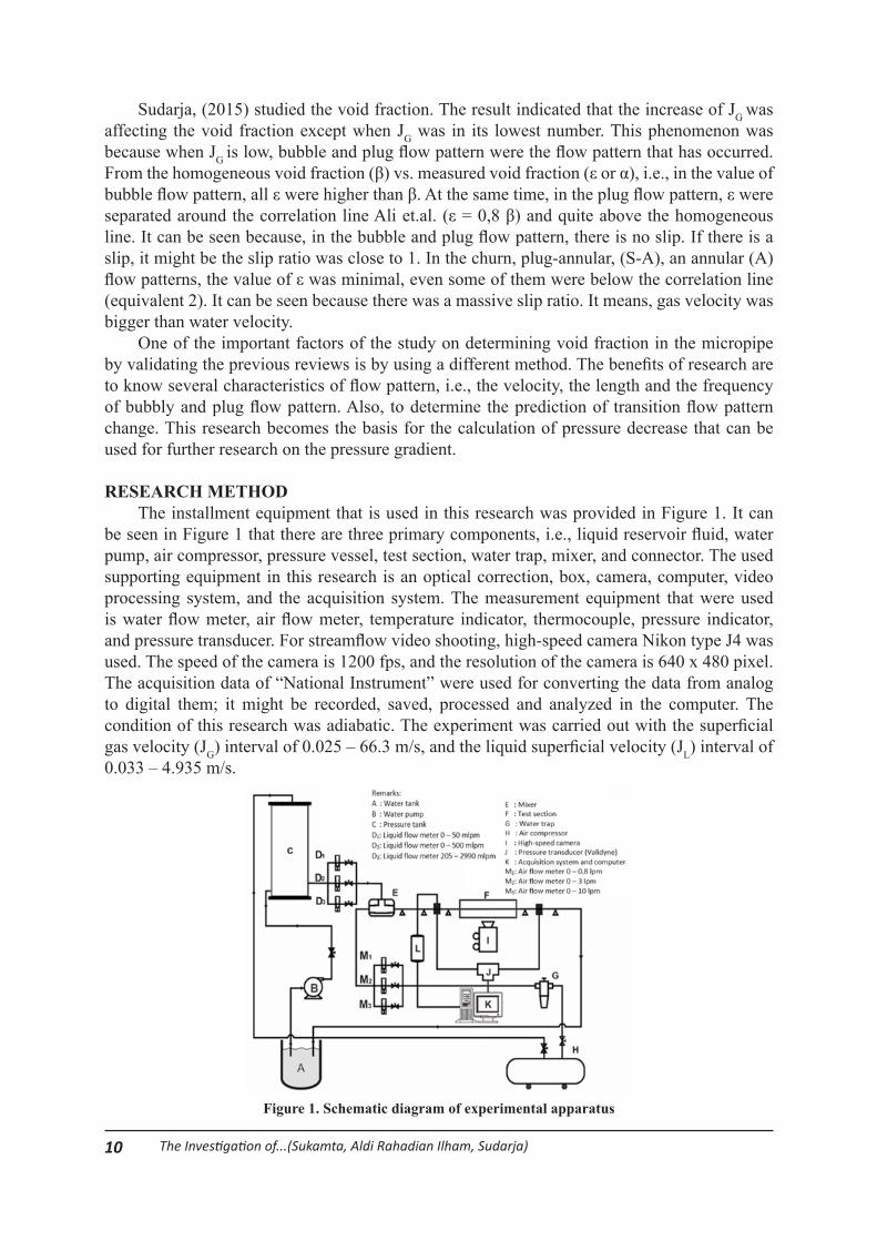
RESEARCH METHODThe installment equipment that is used in this research was provided in Figure 1. It can
be seen in Figure 1 that there are three primary components, i.e., liquid reservoir fluid, water pump, air compressor, pressure vessel, test section, water trap, mixer, and connector. The used supporting equipment in this research is an optical correction, box, camera, computer, video processing system, and the acquisition system. The measurement equipment that were used is water flow meter, air flow meter, temperature indicator, thermocouple, pressure indicator, and pressure transducer. For streamflow video shooting, high-speed camera Nikon type J4 was used. The speed of the camera is 1200 fps, and the resolution of the camera is 640 x 480 pixel. The acquisition data of “National Instrument” were used for converting the data from analog to digital them; it might be recorded, saved, processed and analyzed in the computer. The condition of this research was adiabatic. The experiment was carried out with the superficial gas velocity (JG) interval of 0.025 – 66.3 m/s, and the liquid superficial velocity (JL) interval of 0.033 – 4.935 m/s.
Figure 1. Schematic diagram of experimental apparatus

11Media Mesin: Jurnal Ilmiah Teknik Mesin Vol. 20, No. 1, Januari 2019: 8-17
RESULT AND DISCUSSIONThe research result in the micropipe with a slope of 5 degrees producing some types of
flow pattern which each mixture contains 0%, 10%, 20%, and 30% glycerin. From the research of flow pattern, the flow patterns that were detected in the increase of glycerin percentage are bubbly, plug, slug annular, annular and churn flow pattern. The difference that occurs between several percentages of glycerin is the process of transition among flow patterns. The analysis of void fraction was conducted in the position of 26 pixels (6.879 mm) from the left inlet. The result of the time-average void fraction was then processed to determine the value of Probability Distribution Function (PDF) as the function of ɛ [-] (the value of void fraction).
Void Fraction for the Bubbly Flow PatternThe bubbly flow pattern usually occurs by the presence of air bubbles in the form of small
spheres floating around the boundaries of the pipe wall were shown in Fig. 2. This flow pattern was formed when superficial gas velocity (JG) is low and liquid superficial velocity (JL) is high. The bubbly flow pattern with the percentage mixture of 30% glycerin showed more frequency of occurrence than the percentage of 0%, 10%, and 20% glycerin. It because of the thickening of the liquid which results in heavy air to enter into the sidelines of the pipe.
Figure 2. Bubbly flow pattern with JG = 0.025 m/s and JL = 0.879 m/s
Void Fraction for the Plug Flow PatternThe plug flow pattern is often marked by the air bubbles which cover all the pipe wall with
various lengths of flow pattern, shown in Fig.3. It shows that the plug diameter is similar to the mini pipe diameter. Based on the phase, the plug flow pattern is divided into two, namely air plug and water plug. Plug is the flow pattern which is, based on its shape, categorized as lengthwise bubbly flow (elongated bubbly).

12 The Investigation of...(Sukamta, Aldi Rahadian Ilham, Sudarja)
Figure 3. Plug flow pattern with JG = 0.025 m/s and JL = 0.033 m/s
Void Fraction for the Slug-Annular Flow PatternThe slug-annular flow pattern is a transition pattern from plug pattern to be an annular
pattern. This flow pattern has a structure that the liquid phase is distributed symmetrically on the pipe wall, but on the certain points, there is more liquid film layer which is thicker than on other points. It is because the air when the JG is increasing, the air is trying to penetrate the liquid bridge that separates the air from the plug flow. Thus, the appearance of the liquid film layer is thicker as shown in Fig. 4.
Figure 4. Slug-annular flow pattern with JG = 9.62 m/s and JL = 0.033 m/s
Void Fraction for the Annular Flow PatternThe annular flow pattern is a flow where the high gas superficial velocity (JG) and low liquid
superficial velocity (JL) resulted in the air penetrate the middle part of the liquid film layer thus, pushing the liquid film layer evenly and symmetrically distributed on the pipe wall section. It

13Media Mesin: Jurnal Ilmiah Teknik Mesin Vol. 20, No. 1, Januari 2019: 8-17
is caused by the gas phase that goes through the middle of the water phase. The annular pattern can also be called the continuation of the slug-annular flow pattern as shown in Fig. 5.
Void Fraction for the Churn Flow PatternThe churn flow pattern is formed when the high gas superficial velocity (JG) and a quite
high liquid superficial velocity (JL) have a quite big difference. This flow pattern includes in a very unstable pattern on the tail side so that there is a distorted part as shown in Fig. 6.
Figure 6. Churn flow pattern with JG = 0.025 m/s and JL = 2.297 m/s
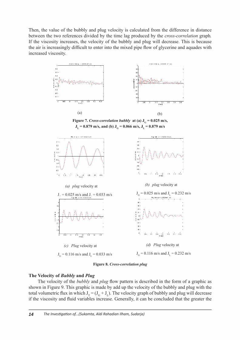
Cross-Correlation of Bubbly and Plug FlowThe velocity of bubbly and plug can be found by deciding the time range in which the
movement between bubbly and plug is in a meeting point of reference to another reference. Figure 7 shows the value of cross-correlation bubbly, while Figure 8 shows the value of cross-correlation plug. Figure 7 and 8 show the fluctuating graphic where there is a value from cross-correlation at the time lag. The highest peak explains the time lag of the cross-correlation results.
14 The Investigation of...(Sukamta, Aldi Rahadian Ilham, Sudarja)
Then, the value of the bubbly and plug velocity is calculated from the difference in distance between the two references divided by the time lag produced by the cross-correlation graph. If the viscosity increases, the velocity of the bubbly and plug will decrease. This is because the air is increasingly difficult to enter into the mixed pipe flow of glycerine and aquades with increased viscosity.
(a) (b)
Figure 7. Cross-correlation bubbly at (a) JG = 0.025 m/s,JL = 0.879 m/s, and (b) JG = 0.066 m/s, JL = 0.879 m/s
(a) plug velocity at
JG = 0.025 m/s and JL = 0.033 m/s
(b) plug velocity at
JG = 0.025 m/s and JL = 0.232 m/s
(c) Plug velocity at
JG = 0.116 m/s and JL = 0.033 m/s
(d) Plug velocity at
JG = 0.116 m/s and JL = 0.232 m/s
Figure 8. Cross-correlation plug
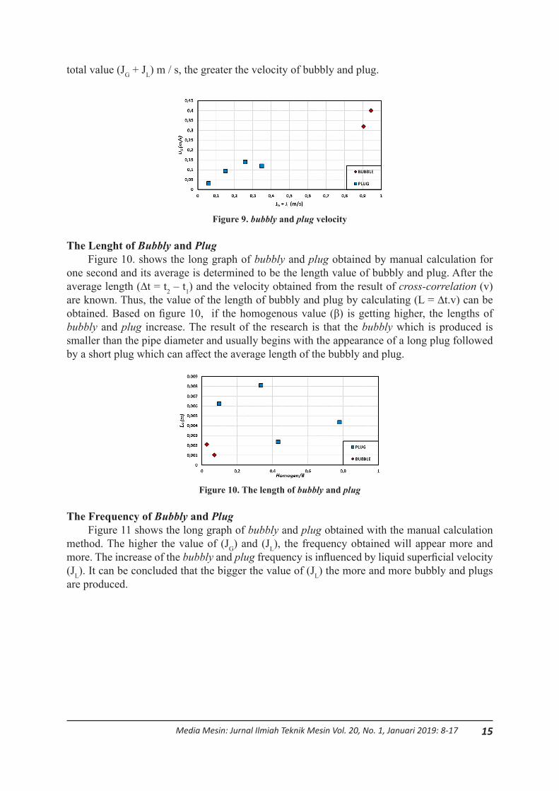
The Velocity of Bubbly and PlugThe velocity of the bubbly and plug flow pattern is described in the form of a graphic as
shown in Figure 9. This graphic is made by add up the velocity of the bubbly and plug with the total volumetric flux in which JT = (JG + JL). The velocity graph of bubbly and plug will decrease if the viscosity and fluid variables increase. Generally, it can be concluded that the greater the
15Media Mesin: Jurnal Ilmiah Teknik Mesin Vol. 20, No. 1, Januari 2019: 8-17
total value (JG + JL) m / s, the greater the velocity of bubbly and plug.
Figure 9. bubbly and plug velocity
The Lenght of Bubbly and PlugFigure 10. shows the long graph of bubbly and plug obtained by manual calculation for
one second and its average is determined to be the length value of bubbly and plug. After the average length (∆t = t2 – t1) and the velocity obtained from the result of cross-correlation (v) are known. Thus, the value of the length of bubbly and plug by calculating (L = ∆t.v) can be obtained. Based on figure 10, if the homogenous value (β) is getting higher, the lengths of bubbly and plug increase. The result of the research is that the bubbly which is produced is smaller than the pipe diameter and usually begins with the appearance of a long plug followed by a short plug which can affect the average length of the bubbly and plug.
Figure 10. The length of bubbly and plug
The Frequency of Bubbly and PlugFigure 11 shows the long graph of bubbly and plug obtained with the manual calculation
method. The higher the value of (JG) and (JL), the frequency obtained will appear more and more. The increase of the bubbly and plug frequency is influenced by liquid superficial velocity (JL). It can be concluded that the bigger the value of (JL) the more and more bubbly and plugs are produced.

16 The Investigation of...(Sukamta, Aldi Rahadian Ilham, Sudarja)
Figure 11. The Frequency of bubbly and plug
CONCLUSIONCharacteristics of the void fraction value of each flow pattern are as follow. The void
fraction value of the bubbly flow pattern is usually begun with plug flow pattern resulting in the increase of the void fraction value drastically in a certain period. In the plug flow pattern, the void fraction value reaches the value of one because the long plug which fills the test section of the pipe .In the slug-annular flow pattern, there is a decrease in the void fraction value. It is because the liquid neck that appears in certain points on the test section. The void fraction value of the annular flow pattern is usually stable because there is no significant decrease and increase. In the churn flow pattern, the void fraction value has a fluctuating value. If JG is getting higher, the void fraction value which is obtained increases. On the other hand, if the JL is getting higher, the void fraction decreases.
Velocity, length, and the frequency of bubbly and plug can be concluded as follow: The flow pattern of bubbly and plug is strongly influenced by its fluid viscosity. It is because if the higher the fluid viscosity, the velocity of the bubbly and plug flow pattern decreases. On the other hand, if the viscosity decreases, the velocity of the bubbly and plug flow pattern increases. The length of bubbly and plug flow pattern is influenced by the higher homogenous value (β). Thus, the length of the pattern increases. Besides the homogenous influence, the length of bubbly and plug pattern is influenced by the value of JG and JL value that is produced. The frequency of the appearance of bubbly and plug is quite high. It causes the void fraction value which is produced increases.
ACKNOWLEDGEMENTThe Ministry of Higher Education, Research and Technology of Indonesia Republic (Grant
PDUPT) and the Universitas Muhammadiyah Yogyakarta financially supported this research
REFERENCE[1] Ali, M.I., Sadatomi, M., Kawaji, M., 1993. Two-phase flow in narrow channels between
two flat plates. Can. J. Chem. Eng., Vol. 71, pp. 657–666. [2] Biksono, Damawidjaya. 2006.“Karakteristik dan Visualisasi Aliran Dua Fasa Pada Pipa
Spiral”. Jurnal Teknik Mesin, Universitas Kristen Petra. 8(2): 69-74. [3] Chung, P.M.-Y., Kawaji, M., 2004. The Effect of Channel Diameter on Adiabatic Two-
Phase Flow Characteristics in The Microchannel. Int. J. Multiphase Flow, Vol. 30, pp. 735-761.
[4] Fukano, T., Kariyasaki, A., 1993, Characteristic of Gas-Liquid Two-Phase Flow in a Capillary Tube, Nuclear Engineering and Design, Vol. 141, pp. 59-68.

17Media Mesin: Jurnal Ilmiah Teknik Mesin Vol. 20, No. 1, Januari 2019: 8-17
[5] Kawahara, A., Chung, P.M.Y., Kawaji, M., 2002, Investigation of Two-Phase Flow Pattern, Void Fraction and Pressure Drop in a Microchannel, International Journal of Multiphase Flow, Vol. 28, pp. 1411-1435.
[6] Mayor, T.S., Pinto, A.M.F.R., Campos, J.B.L.M., 2007, An Image Analysis Technique for The Study of Gas-Liquid Slug Flow along Vertical Pipes – Associated Uncertainty, Flow Measurement and Instrumentation, Vol 18, pp. 139-147.
[7] Montoya, G.A., Deendarlianto, Lucas, D., Hohne, T., Vallee, C., 2012. Image Processing Based Study of Interfacial Behavior of the Countercurrent Gas-Liquid Two-Phase Flow in Hot Leg of a PWR. Science and Technology of Nuclear Installations, Vol. 2012, pp. 1-10.
[8] Sudarja, Deendarlianto, Indarto, Haq. A., 2015, Experimental study on the void fraction of air-water two-phase flow in a horizontal circular mini-channel
[9] Triplett K.A., Ghiaasiaan, S.M., Abdel-Khalik, S.I., Sadowski, D.I., 1999, Gas-Liquid Two-Phase Flow in Microchannels Part II: void fraction and pressure drop, International Journal of Multiphase Flow, Vol. 25, pp. 395-410.
[10] Wallis, G. B., 1969, One-Dimensional Two-Phase Flow, McGraw-Hill, New York.
Related Documents