The Invention and Development of the Radiosonde with A Catalog of Upper-Atmospheric Telemetering Probes in the National Museum of American History, Smithsonian Institution JOHN L. DUBOIS, ROBERT P. MULTHAUF, and CHARLES A. ZIEGLER SMITHSONIAN INSTITUTION PRESS

Welcome message from author
This document is posted to help you gain knowledge. Please leave a comment to let me know what you think about it! Share it to your friends and learn new things together.
Transcript

The Invention and Development of the Radiosonde
with A Catalog of Upper-Atmospheric Telemetering Probes
in the National Museum of American History, Smithsonian Institution
JOHN L. DUBOIS, ROBERT P. MULTHAUF, and CHARLES A. ZIEGLER
SMITHSONIAN INSTITUTION PRESS
SERIES PUBLICATIONS OF THE SMITHSONIAN INSTITUTION
Emphasis upon publication as a means of "diffusing knowledge" was expressed by the first Secretary of the Smithsonian. In his formal plan for the Institution, Joseph Henry outlined a program that included the following statement: "It is proposed to publish a series of reports, giving an account of the new discoveries in science, and of the changes made from year to year in all branches of knowledge." This theme of basic research has been adhered to through the years by thousands of titles issued in series publications under the Smithsonian imprint, commencing with Smithsonian Contributions to Knowledge in 1848 and continuing with the following active series:
Smithsonian Contributions to Anthropology
Smithsonian Contributions to Botany
Smithsonian Contributions to the Earth Sciences Smithsonian Contributions to the Marine Sciences
Smithsonian Contributions to Paleobiology
Smithsonian Contributions to Zoology Smithsonian Folklife Studies
Smithsonian Studies in Air and Space
Smithsonian Studies in History and Technology
In these series, the Institution publishes small papers and full-scale monographs that report the research and collections of its various museums and bureaux or of professional colleagues in the world of science and scholarship. The publications are distributed by mailing lists to libraries, universities, and similar institutions throughout the world.
Papers or monographs submitted for series publication are received by the Smithsonian Institution Press, subject to its own review for format and style, only through departments of the various Smithsonian museums or bureaux, where the manuscripts are given substantive review. Press requirements for manuscript and art preparation are outlined on the inside back cover.
Lawrence M. Small Secretary Smithsonian Institution
S M I T H S O N I A N S T U D I E S I N H I S T O R Y A N D T E C H N O L O G Y • N U M B E R 5 3
The Invention and Development of the Radiosonde, with a Catalog
of Upper-Atmospheric Telemetering Probes in the National Museum of American History,
Smithsonian Institution
John L. DuBois, Robert P. Multhauf, and Charles A. Ziegler
Smithsonian Institution Press
Washington, D.C.
2002
A B S T R A C T
DuBois, John L., Robert P. Multhauf, and Charles A. Ziegler. The Invention and Development of the Radiosonde, with a Catalog of Upper-Atmospheric Telemetering Probes in the National Museum of American History, Smithsonian Institution. Smithsonian Studies in History and Technology, number 53, 78 pages, 60 figures, 2002.—From a historical perspective, the radiosonde is one of the more significant technological innovations of the twentieth century, not only because its widespread use greatly enhanced the accuracy of weather forecasting, but also because some features of its basic design became the foundation of all modern analog telemetry systems. This study examines the way in which advances in the technology of non-telemetering balloonsondes and radio in the nineteenth and twentieth centuries culminated in the invention of the radiosonde in 1929. The subsequent development of radiosondes in Europe and the United States from 1929 to 1940 is traced in detail, when the basic design of this instrument achieved its modern form. An overview of significant modifications in radiosonde design after 1940 also is provided because the instruments have remained an essential meteorological tool in the twenty-first century. This monograph also includes a catalog of radiosondes in the Smithsonian Institution's National Museum of American History. Photographs of instruments in this unique collection that graphically depict the development stages of the radiosonde are presented.
OFFICIAL PUBLICATION DATE is handstamped in a limited number of initial copies and is recorded in the Institution's annual report, Annals of the Smithsonian Institution. COVER DESIGN: The first true radiosonde, which was flown by Robert Bureau in 1929.
Library of Congress Cataloging-in-Publication Data DuBois, John L. The invention and development of the radiosonde : with a catalog of upper-atmospheric telemetering probes in
the National Museum of American History, Smithsonian Institution / John L. DuBois, Robert P. Multhauf, and Charles A. Ziegler.
p. cm.—(Smithsonian studies in history and technology ; no. 53) Includes bibliographical references. 1. Radiosondes—History—19th Century. 2. Radiosondes—History—20th century. 3. Radiosondes—
Catalogs. 4. National Museum of American History (U.S.)—Catalogs. I. Multhauf, Robert P. II. Ziegler, Charles A. (Charles Albert), 1927- III. Title. IV. Series.
QC879.25.D83 2002 551.63'52—dc21 2002030658
© The paper used in this publication meets the minimum requirements of the American National Standard for Permanence of Paper for Printed Library Materials Z39.48—1984.

Contents
Page
Preface iv Introduction 1
I. THE PROBLEM OF HIGH-ALTITUDE METEOROLOGY AND THE TECHNOLOGY
THAT LED TO THE RADIOSONDE
1. Nontelemetering Balloonsondes, 1892-1929 3 2. Preradio Telemetering, 1842-1894 15 3. Radio Telemetry, 1895-1929 19
II. THE RADIOSONDE: DEVELOPMENT AND APPLICATION
4. The Early Years, 1921-1928 26 5. The Prototypes, 1929-1930 30 6. Maturity, 1931-1940 41 7. The Radiosonde after 1940 59 8. Conclusion 67
III. CATALOG OF UPPER-ATMOSPHERIC TELEMETERING PROBES AND RELATED
ARTIFACTS IN THE NATIONAL MUSEUM OF AMERICAN HISTORY,
SMITHSONIAN INSTITUTION
Notes 73 Appendix: Selected United States Patents Related to Radiosondes 75 Literature Cited 76
in
Preface
"Radiosonde" is a balloon-borne instrument that transmits atmospheric data, usually temperature, pressure, and humidity, to a receiver-recorder on the ground. The contributions of this relatively simple device to the late twentieth-century way of life can hardly be exaggerated. No other factor contributed more to the systematization of weather observations, which is beneficial to all who depend upon meteorological prediction. The utilization of the radiosonde directly affected agriculture and aeronautics, and its more sophisticated offspring made possible many of the marvels of the space age.
The collection of instruments on which this study is based was assembled throughout a decade and a half, 1955-1970, as part of the program of the Smithsonian Institution to establish a new museum of the history of science and technology and of the political and social history of the United States.
A museum rarely exhibits its entire collection in any field at one time, and objects not exhibited are retained for reference purposes. In the latter function, nothing is more useful than a printed catalog. Because of the variety of museum collections, the production of such catalogs is only occasionally realized. Such a document is most important when the collection in question is uncommon, or even unique. This may be the case with the collection described herein.
Because "old" scientific instruments often are unfamiliar even to those who use modem instruments serving the same, or similar, purposes, some guidance in their construction and functions is useful. It also is important to understand that the history of a scientific instrument is a case history in the process of invention. For these reasons, this publication includes a capsule history of the development of the radiosonde based upon the instruments themselves and upon the original literature connected with their development.
We are particularly indebted to Robert Wright of the Instrument Division of the United States Weather Bureau, who thought old instruments worth collecting, and to Christon Harmantas, who knew what they were. George A. Norton, Jr., assisted greatly with the catalog of specimens.
We also gratefully acknowledge the help of William Blair, Jr., who kindly supplied us with copies of selected published and unpublished documents from the collected papers of his father, Colonel William Blair. Thanks also are due H.C. McBrair who alerted us to the importance of Colonel Blair's research to the early history of the radiosonde and who shared with us his reminiscences of radiosonde development at Wallace and Tiernan Inc., an early manufacturer of radiosonde equipment. At the opposite end of the time-span with which we are concerned, we are indebted for the support of the following historians at the Smithsonian Institution: David Devorkin of the National Air and Space Museum and Deborah Warner of the National Museum of American History.
Robert P. Multhauf Director Emeritus National Museum of American History Smithsonian Institution
IV

The Invention and Development of the Radiosonde, with a Catalog
of Upper-Atmospheric Telemetering Probes in the National Museum of American History,
Smithsonian Institution
John L. DuBois, Robert P. Multhauf, and Charles A. Ziegler
Introduction
The collection and transmission of data is as old as the human species. Information about the weather may have first achieved "scientific" status when sensible observation (e.g., coldest winter in the memory of the oldest resident) of meteorological data was augmented by instruments capable of numerically describing the elements of the weather.
The invention, in the seventeenth century, of the thermometer, barometer, hygrometer, and wind speed and direction indicators, was a phenomenon of the scientific revolution. These were hardly comparable in importance with some other inventions of the time, such as the telescope, whose revelations spectacularly embellished astronomy, the already crowned "queen" of the sciences. Astronomy already was mathematicized, whereas the "science" of the meteorologist still was difficult to distinguish from the art of the occultist. Still, instruments and the numerical recording of data gave hope for scientific respectability, and, by the end of the eighteenth century, the collection of meteorological data was one of the principle concerns of the numerous scientific societies that were part of the scientific revolution. Their periodical publications, the first of which was established in the 1660s, were devoted primarily to the dissemination of meteorological information.
By the end of the seventeenth century, attempts had been
John L. DuBois, C.E.O. Thermalogic Corporation, Hudson, Massachusetts, 01749. Robert P. Multhauf, Director Emeritus, National Museum ofAmericam History, Smithsonian Institution, Washington, D.C. 20560. Charles A. Ziegler, lecturer in Anthropology, Brandeis University, Waltham Massachiusetts 02453-2700.
made to develop meteorological instruments that automatically recorded their readings. Steady improvements were made in the data collection process, but it soon was recognized that it was even more important to devise some speedy method for transmitting the data from various collection points to a central bureau. One means to accomplish this task existed in the eighteenth century. The visual telegraph, which used lanterns and mechanized semaphores, was invented in 1794 by a French officer, Claude Chappe. Its primary purpose was to improve military communications, but because weather conditions were of vital military importance, both the collection and transmission of meteorological data increasingly were made ancillary to the military art. In the United States, the army played a key role in both the collection and the transmission of meteorological data via the electromagnetic telegraph, which was introduced in the 1840s.
Yet, by the early twentieth century, the transmission of meteorological data still was a minor application of the electromagnetic telegraph. The introduction of the wireless telegraph (radio) did little to change this, although experiments in the automatic transmission of data from remote meteorological instruments, including the transmission by wire from balloons, continued until the 1920s, when radio transmission was adopted.
There were logical reasons for this lack of progress. The accumulated mass of meteorological data had not greatly improved weather prognostication, and its collection was not considered urgent. The meteorologist had not only failed, as was often charged, to "do something about the weather," but had a
SMITHSONIAN STUDIES IN HISTORY AND TECHNOLOGY
poor record for prognostication. Meteorology remained an embarrassment to practioners of the exact sciences, who increasingly were tempted to relegate it to the closet reserved for sciences that had failed to yield to the magic of mathematization.
It wasn't until the 1920s that there was a marked improvement in meteorology. Geophysical and weather-related problems of radio transmission had increased interest within the scientific community in the collection of atmospheric data from the stratosphere (Shaw, 1926, 1942; Stringer, 1972). There also was increased military awareness of the uses of meteorological data. In the civilian sector, the advantage to farmers and fishermen of improved weather prognostication and the crucial dependence upon meteorology of the new technology of aviation, had become apparent. Moreover, although the impetus to improve instrumental meteorology can be traced to the interests and needs of these segments of society, the advent of the radiosonde owed much to an almost accidental development, amateur radio—a hobby stemming from a widespread fascination with this new mode of communication and its "off-the-shelf technology.
The efflorescence of amateur radio after World War I not only produced technological advances but also created a large market that dramatically lowered the cost of radio components. In the 1930s, the radiosonde was rapidly adopted by the weather bureaus of virtually all the industrialized nations. During the 1940s, the innovations in radio resulting from the development of the radiosonde, spurred by pressure from military programs, spawned the new technology of multichannel data telemetry.
During and after World War II, the needs of aviation and of rocket engineering to capture massive amounts of data simultaneously (in "real time") from many sources were met by the further development of the principles and designs used to develop the radiosonde. Workers in Europe and the United States, who had specialized in balloonsonde or radiosonde research, applied their skills to develop rocket-borne instrumentation for atmospheric research (Kuiper, 1946:263). In the 1950s, data telemetry scientists used complex methods of radio modulation and transmission to enhance by several orders of magnitude the speed and accuracy of data transmission. Modern probes for exploring the upper atmosphere and space represented yet another advance in the three areas of technology originally merged in the radiosonde: environmental sensors, data trans
mission via radio, and an unmanned vehicle capable of moving the sensors and transmitter away from the earth's surface.
The development of the radiosonde, from a historical perspective, is important not only because these balloon-borne instruments still are widely used today, but also because the radiosonde represents a technological link between the nontele-metering, balloon-borne probes of the pre-1930s and modern rocket-launched probes. Moreover, the chronological portion of the radiosonde's history that is the focus of this monograph (1929 to 1940) is especially important because it was during those years that the basic design features of radiosondes evolved, and because these developments laid the foundation for the introduction in the 1940s of multichannel radio transmission via subcarrier modulation (the basis for all modern analog radiotelemetry systems).
The reason for this publication is the presence of a substantial collection of significant examples of the radiosonde in the National Museum of American History (NMAH), Smithsonian Institution. If, as appears to be the case, this is the only large collection of radiosonde instruments extant, it constitutes a unique resource for studying the history of radio telemetry and the history of one of the earliest applications of radio to the solution of problems in another technology.
In order to understand the development of the radiosonde, the first three sections describe the relevant advances in balloon-borne instruments, preradio telemetry, and radio telemetry prior to 1929. The next sections outline the historical development of the radiosonde from its invention to the present. Finally, there is a catalog of the radiosondes in the collection of the National Museum of American History, Smithsonian Institution.
Units are given in the metric system throughout this text. This has been done for simplicity and because metric units are standard in the field of meteorology.
ARC AT&T NBS NPL ONR Plaskon RCA USWB WIT
ABBREVIATIONS
Atlantic Research Co. American Telegraph and Telephone National Bureau of Standards British National Physics Laboratory United States Office of Naval Research Plaskon Co., 2121 Sylvan Ave., Toledo, Ohio Radio Corporation of America United States Weather Bureau Washington Institute of Technology
I. The Problem of High-Altitude Meteorology and the Technology that Led to the Radiosonde
1. Nontelemetering Balloonsondes, 1892-1929
Prior to the invention of the balloon in the late eighteenth century, rockets and kites were the only two vehicles capable of ascending into the atmosphere. The rocket was known in China by the early part of the thirteenth century, and it already was being used in Europe for military purposes before the end of that century. Kites, used as children's toys for many centuries in Asia, were introduced in Europe in the early seventeenth century. In 1749, British astronomer Alexander Wilson flew thermometers on kites to measure air temperature at high altitudes. This was perhaps the first recorded use of an unmanned atmospheric probe. Three years later, Benjamin Franklin performed his celebrated kite experiment on the nature of lightning.
Rockets were quite unsuitable as instrument platforms before recent times; indeed this application probably was not considered. Kites also were not used often as probes until the advent of the Hargrave box kite in 1893. Manned flights to obtain scientific data became possible after 1783, using free balloons; but the captive balloon, because of its tendency to oscillate and rotate, was seldom used. Those defects were rectified with the invention of the Siegfried and Parseval kite-balloon in 1898. After the turn of the century, both instrumented box kites and kite-balloons were used by national weather services in Europe and the United States to obtain upper air data (Middleton, 1969a:98).
By 1929, a considerable amount of geophysical data had been gathered, using kites, unmanned captive and free balloons, manned balloons, and airplanes. The history of such research, however, lies outside the scope of this monograph and will be discussed only insofar as the instrumentation developed for use with such vehicles influenced the design of instruments flown on unmanned free balloons.
The use of the unmanned free balloon to obtain scientific data followed closely the introduction of the balloon itself. In August 1783, Jacques Charles, a French Professor of physics, launched at Paris an improved version of the recently invented hot-air balloon. In this balloon hydrogen replaced heated air as the gas fill. The path of Charles' balloon was tracked by several observers organized by Jean-Baptiste Meusnier, a young army engineer, who obtained data about the atmospheric forces exerted on the balloon (Gillespie, 1983:32). Meusnier's work constituted the first practical use of unmanned and uninstru-
mented free balloons (later called "pilot" balloons) for scientific research.
Throughout the nineteenth century, small pilot balloons often were released prior to launching a manned balloon, in order to estimate the winds aloft. It was not until the first decade of the twentieth century, however, that accurate measurements of wind velocity at various altitudes, using a theodolite technique to track pilot balloons, became an accepted meteorological tool (Blair and Lewis, 1931:1532).
The practice of attaching instruments to an unmanned free balloon was started in France in 1892 by Gustave Hermite, with the help of a noted balloonist, Georges Besancon (Hermite, 1893). These early versions of what came to be called a "balloonsonde" used small (five cubic meter) coal-gas-filled balloons made of varnished paper that were capable of carrying self-registering thermometers and barometers. Later versions used balloons made of goldbeater's skin (the outer layer of the caecum of an ox), and, for heavier payloads containing clockwork recorders, silk balloons with volumes of several hundred cubic meters were used (de Fonvielle, 1899:1-22). Payload weight and lifting capacity were designed to ascend to about nine kilometers before loss of gas, through the open neck of the balloon and by diffusion through its skin, caused the balloon to descend. This technique insured a slow descent and a reasonably soft landing. Because of the prolonged floating period, balloons often landed as far as one hundred kilometers from the launch site. This dispersion exacerbated the problem of data retrieval, which depended upon the finder mailing the payload back to the investigator's laboratory where the recorder could be read and interpreted. Sometimes balloonsondes were lost, but even when they were found, several days or even weeks elapsed before the data were recovered. Despite this disadvantage, the balloonsonde was capable of returning data from much higher altitudes than kites, captive balloons, or manned free balloons (Middleton, 1969a:99; 1969b:97-102).
The discovery of the tropopause by French scientist Teisser-enc de Bort, announced in 1902, was made with a balloonsonde. The tropopause, a transition zone between the troposphere and the stratosphere, marks the point at which air temperature ceases to drop with increasing altitude. It begins at about 11.2 kilometers, an altitude considerably beyond the maximum heights attained by kites and captive balloons (due to the weight of the tether) (Teisserenc de Bort, 1899:
SMITHSONIAN STUDIES IN HISTORY AND TECHNOLOGY
^ w W
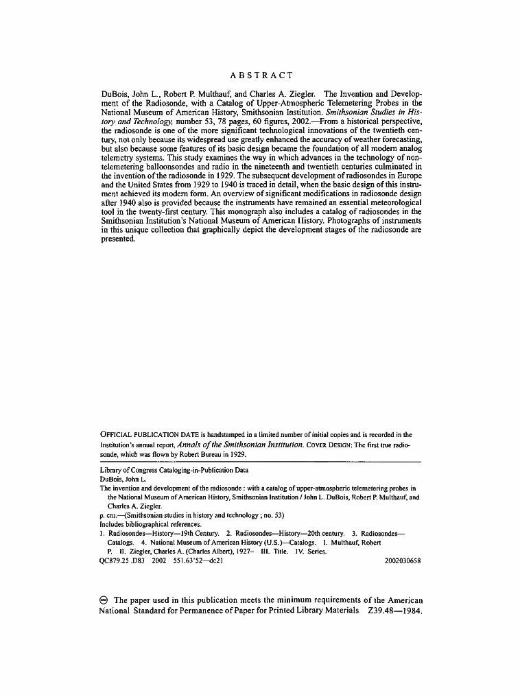
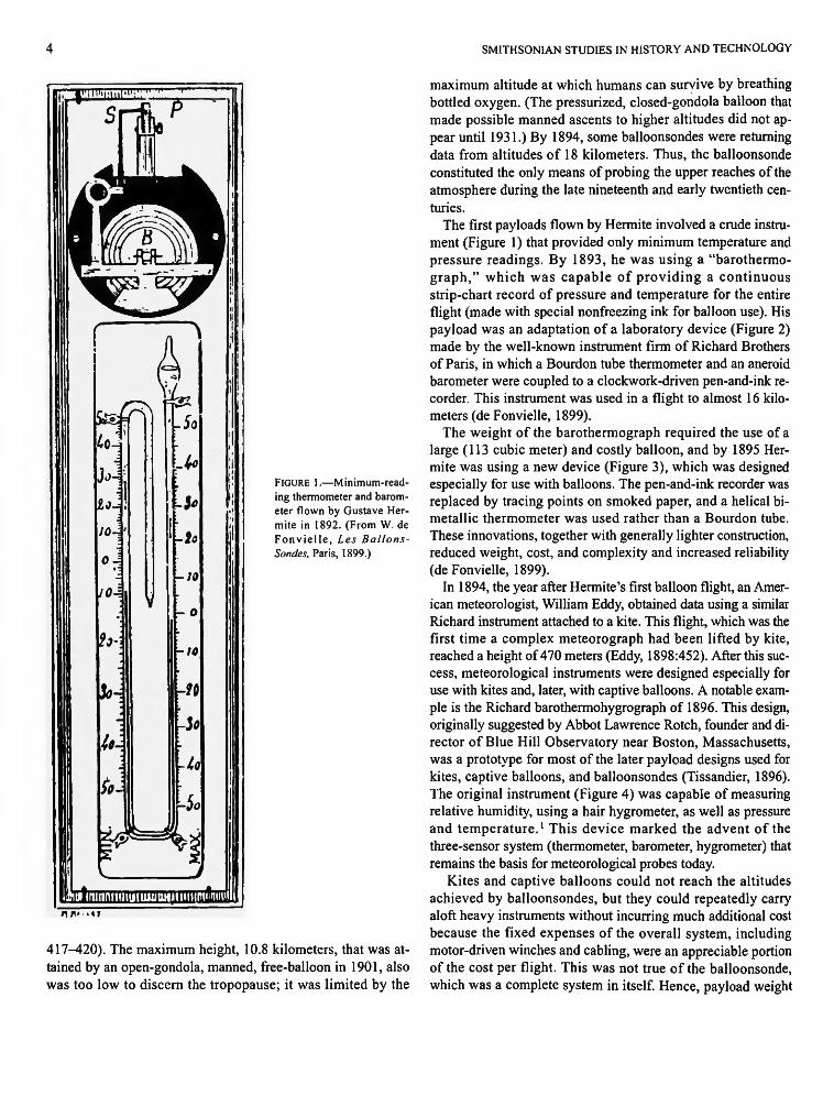
FIGURE 1.—Minimum-reading thermometer and barometer flown by Gustave Her-mite in 1892. (From W. de Fonvielle, Les Ballons-Sondes, Paris, 1899.)
417^420). The maximum height, 10.8 kilometers, that was attained by an open-gondola, manned, free-balloon in 1901, also was too low to discern the tropopause; it was limited by the
maximum altitude at which humans can survive by breathing bottled oxygen. (The pressurized, closed-gondola balloon that made possible manned ascents to higher altitudes did not appear until 1931.) By 1894, some balloonsondes were returning data from altitudes of 18 kilometers. Thus, the balloonsonde constituted the only means of probing the upper reaches of the atmosphere during the late nineteenth and early twentieth centuries.
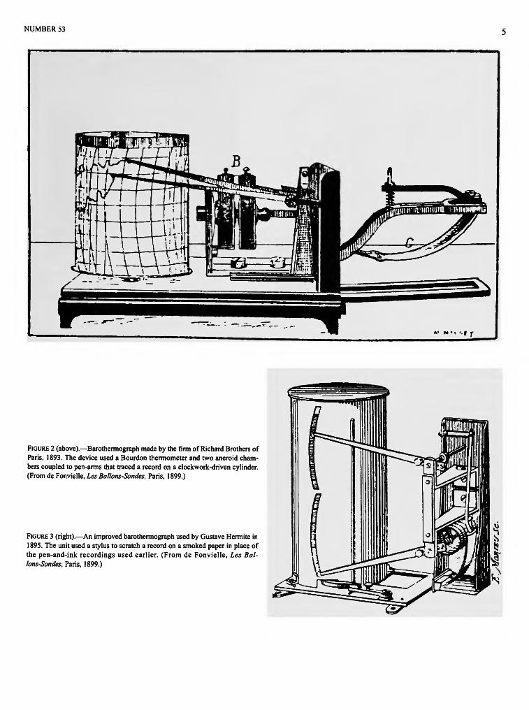
The first payloads flown by Hermite involved a crude instrument (Figure 1) that provided only minimum temperature and pressure readings. By 1893, he was using a "barothermo-graph," which was capable of providing a continuous strip-chart record of pressure and temperature for the entire flight (made with special nonfreezing ink for balloon use). His payload was an adaptation of a laboratory device (Figure 2) made by the well-known instrument firm of Richard Brothers of Paris, in which a Bourdon tube thermometer and an aneroid barometer were coupled to a clockwork-driven pen-and-ink recorder. This instrument was used in a flight to almost 16 kilometers (de Fonvielle, 1899).
The weight of the barothermograph required the use of a large (113 cubic meter) and costly balloon, and by 1895 Hermite was using a new device (Figure 3), which was designed especially for use with balloons. The pen-and-ink recorder was replaced by tracing points on smoked paper, and a helical bimetallic thermometer was used rather than a Bourdon tube. These innovations, together with generally lighter construction, reduced weight, cost, and complexity and increased reliability (de Fonvielle, 1899).
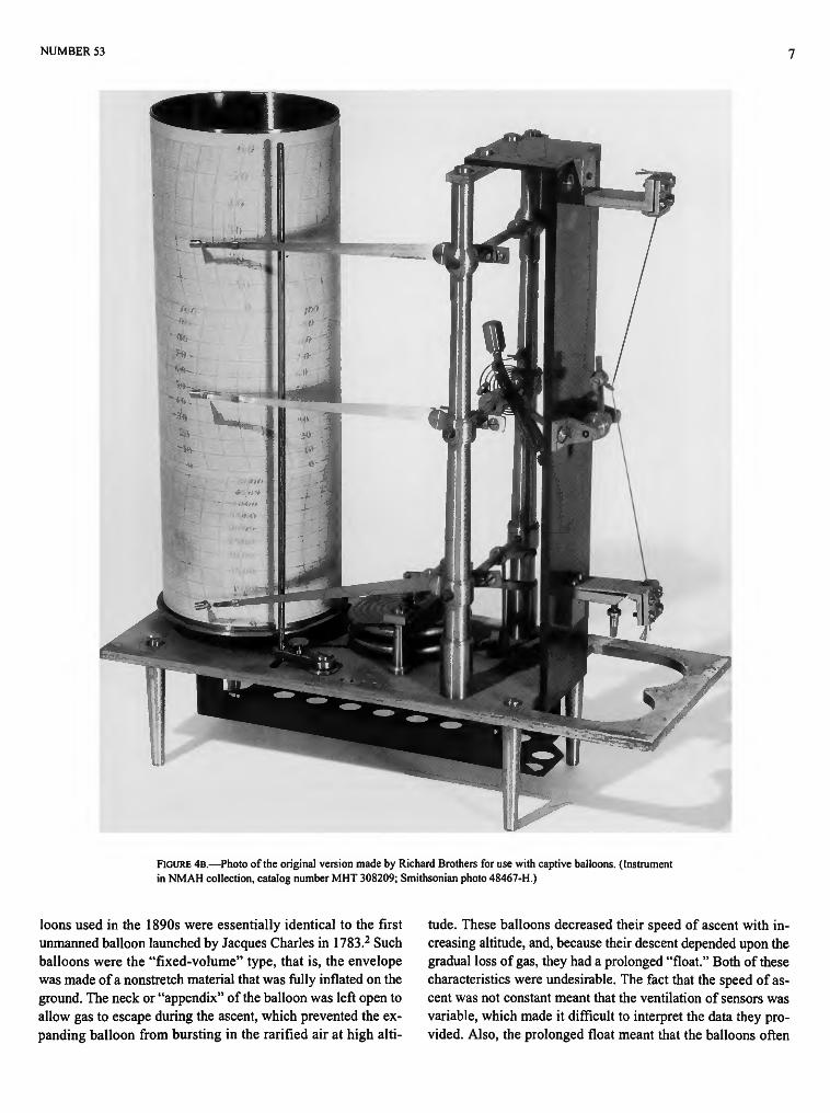
In 1894, the year after Hermite's first balloon flight, an American meteorologist, William Eddy, obtained data using a similar Richard instrument attached to a kite. This flight, which was the first time a complex meteorograph had been lifted by kite, reached a height of 470 meters (Eddy, 1898:452). After this success, meteorological instruments were designed especially for use with kites and, later, with captive balloons. A notable example is the Richard barothermohygrograph of 1896. This design, originally suggested by Abbot Lawrence Rotch, founder and director of Blue Hill Observatory near Boston, Massachusetts, was a prototype for most of the later payload designs used for kites, captive balloons, and balloonsondes (Tissandier, 1896). The original instrument (Figure 4) was capable of measuring relative humidity, using a hair hygrometer, as well as pressure and temperature.1 This device marked the advent of the three-sensor system (thermometer, barometer, hygrometer) that remains the basis for meteorological probes today.
Kites and captive balloons could not reach the altitudes achieved by balloonsondes, but they could repeatedly carry aloft heavy instruments without incurring much additional cost because the fixed expenses of the overall system, including motor-driven winches and cabling, were an appreciable portion of the cost per flight. This was not true of the balloonsonde, which was a complete system in itself. Hence, payload weight
NUMBER 53
FIGURE 2 (above).—Barothermograph made by the firm of Richard Brothers of Paris, 1893. The device used a Bourdon thermometer and two aneroid chambers coupled to pen-arms that traced a record on a clockwork-driven cylinder. (From de Fonvielle, Les Ballons-Sondes, Paris, 1899.)
FIGURE 3 (right).—An improved barothermograph used by Gustave Hermite in 1895. The unit used a stylus to scratch a record on a smoked paper in place of the pen-and-ink recordings used earlier. (From de Fonvielle, Les Ballons-Sondes, Paris, 1899.)

SMITHSONIAN STUDIES IN HISTORY AND TECHNOLOGY
UitiiiiiiltiUizt^r.ir.u
..-:rs::nsi£:«u:uu: I I I I . I I M. I » » « » • • j l g f • I • I i i l i i i n j • « • • « • • • • * « • *
i m • H I • i i , i - • * « » * « • * > * • • • • >
• < > I-™ I ! ! i ! O T » • ' • • ' « • • • • •
I I I 1 * 1 1 I J « » l » • • • • • • < > ^ » i i • 14 ' ' I •" • •• I H U H • * • # • * *
I .< !<i»St >< i i •»»»•• • i •»;?^ x ^ l > 4 * • ! • • • • • • • • * r » * # •« •« i *<* . * • « I. < I . .. » * . • . . . , * . . < ^ «« 1 ' « * • « » • • • « • • * • » » • » - • • *
* • * * • * * * * * * :
it
FIGURE 4A.—Barothermohydrograph made by the firm of Richard Brothers of Paris in 1896 for American meteorologist A.L. Rotch. (From G. Tissandier, La Nature, volume 24, 1896.)
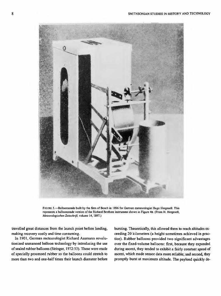
was reflected in the size and cost of the balloon, and this significantly affected the cost per launch. Thus, although the Richard barothermohygrograph was suitable for use with kites and captive balloons, lighter mechanisms were desirable for use with unmanned balloons. In 1896, at the request of Hugo Hergesell of the Strasbourg Observatory, lighter instruments (Figure 5) were designed by the German firm of Bosch and were used in an experiment in which balloonsondes were launched simultaneously in Germany, France, and Russia (Hergesell, 1897). This was the first international attempt to obtain synoptic meteorological data on the upper atmosphere.
Pressure-, temperature-, and humidity-measuring payloads were not the only types developed and flown. As early as 1899, French scientist A. de la Baume-Pluvinel constructed and flew a sophisticated balloonsonde for solar spectroscopy (Figure 6). A clockwork mechanism opened and, after a brief interval, closed the slit of a spectrometer at a preset time during the flight, allowing the solar spectrum to be recorded on photographic film. During this interval, the image of the recording arm of a barometer was projected onto the film so that pressure (and altitude) could be correlated with spectral data. Perhaps the most innovative aspect of this balloonsonde was the use of a compass-like magnetic frame to align the sonde (which could rotate around its longitudinal axis) with the earth's magnetic field. The heliostat mirror was tilted slightly, so that the noontime sun's zenith distance was such as to reflect sunlight directly into the slit that was opened by the clockwork timer. This
is the earliest example of the use of an automatic, solar, homing device in a geophysical probe. Indeed, conceptually Baume-Pluvinel's balloonsonde represented an extraordinary precursor of a late twentieth-century design (Baume-Pluvinel, 1903).
Baume-Pluvinel's use of photographic film to record simultaneously the output from more than one sensor not only allowed the correlation of several parameters, but also was parsimonious in providing needed information with minimal equipment (advantageous in balloonsondes where low weight and reliability were important considerations). Moreover, it demonstrated that it was possible to record mechanical displacement by nonmechanical means, i.e., photographically, in a balloonsonde. This technique subsequently was applied to other types of instruments based upon the measurement of mechanical displacement, where a direct physical linkage between the displaced structure and a recording mechanism would be difficult to construct and/or would destroy the accuracy of the measurement (e.g., in measuring the height of mercury in a thermometer or the separation of the fibers of an electrometer). The advantageous features of the photographic technique made it the preferred method for investigators who sought to build payloads for obtaining data not available from the standard meteorological balloonsonde.
At the turn of the century, the development of the rubber balloon dramatically altered unmanned balloon technology and made low cost and low weight even more important in designing balloonsondes. With the exception of the gas fill, the bal-
NUMBER 53
FIGURE 4B.—Photo of the original version made by Richard Brothers for use with captive balloons. (Instrument in NMAH collection, catalog number MHT 308209; Smithsonian photo 48467-H.)
loons used in the 1890s were essentially identical to the first unmanned balloon launched by Jacques Charles in 1783.2 Such balloons were the "fixed-volume" type, that is, the envelope was made of a nonstretch material that was fully inflated on the ground. The neck or "appendix" of the balloon was left open to allow gas to escape during the ascent, which prevented the expanding balloon from bursting in the rarified air at high alti
tude. These balloons decreased their speed of ascent with increasing altitude, and, because their descent depended upon the gradual loss of gas, they had a prolonged "float." Both of these characteristics were undesirable. The fact that the speed of ascent was not constant meant that the ventilation of sensors was variable, which made it difficult to interpret the data they provided. Also, the prolonged float meant that the balloons often
SMITHSONIAN STUDIES IN HISTORY AND TECHNOLOGY
FIGURE 5.—Balloonsonde built by the firm of Bosch in 1896 for German meteorologist Hugo Hergesell. This represents a balloonsonde version of the Richard Brothers instrument shown in Figure 4B. (From H. Hergesell, Meteorologischen Zeitschrift, volume 14, 1897.)
travelled great distances from the launch point before landing, making recovery costly and time consuming.
In 1901, German meteorologist Richard Assmann revolutionized unmanned balloon technology by introducing the use of sealed rubber balloons (Stringer, 1972:53). These were made of specially processed rubber so the balloons could stretch to more than two and one-half times their launch diameter before
bursting. Theoretically, this allowed them to reach altitudes exceeding 20 kilometers (a height sometimes achieved in practice). Rubber balloons provided two significant advantages over the fixed-volume balloons: first, because they expanded during ascent, they tended to exhibit a fairly constant speed of ascent, which made sensor data more reliable; and second, they promptly burst at maximum altitude. The payload quickly de-

NUMBER 53
FIGURE 6.—Solar-homing balloonsonde built and flown by French scientist A. de la Baume-Pluvinel in 1899. The purpose of this sophisticated device was to measure part of the solar spectrum at high altitudes where radiation traverses only a small portion of the earth's atmosphere. (From A. de la Baume-Pluvinel, L'Aerophile, volume 2, 1903.)
scended on a parachute, which considerably reduced recovery times. Moreover, such balloons offered two means of payload recovery: descent by a single parachute, which was used with low-cost payloads when timely recovery was important, and the multiple-balloon technique, which was used with costly, one-of-a-kind payloads when a soft landing and a high probability of retrieval were essential. The first method became standard for meteorological balloonsondes, whereas the second was characteristic of research flights involving hard-to-replace special instrumentation (for example, with the first radiosonde).
The multiple-balloon technique (which depended upon the use of rubber balloons) was introduced by Hergesell in 1904. The single balloon and parachute combination was replaced by two or more smaller balloons of equivalent lifting power. Although the balloons were designed to burst at roughly the same altitude, it was certain that one balloon would burst before the others, allowing the remaining balloons and the payload to descend slowly to a soft landing. This method enhanced the likelihood of retrieval because the remaining balloon(s) floated above the grounded payload, acting as a signal to potential finders (Hergesell, 1904:200).
Although rubber balloons were not reusable (as were balloons made of silk or goldbeater's skin), they were less costly; hence, the average cost per flight was not appreciably higher. Moreover, the new balloon technology promised even greater cost reduction if payloads could be lightened and rubber balloons made smaller. This in turn suggested the possibility of sending up large numbers of balloonsondes, making the possibility of routinely obtaining synoptic data on the upper atmosphere a meteorological reality.
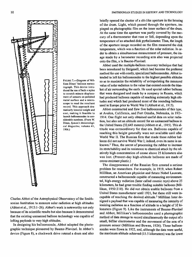
William Dines was the first to solve the payload weight problem (Dines, 1906:101) by eliminating the costly clockwork-driven recorder and the complicated mechanical linkages between sensor arm and recording arm and substituting a small, highly polished, flat, metal surface on which the arm of the sensor scratched a line (Figure 7). The total deflection was very small, necessitating the use of a microscope to read the recording, but this was a small price to pay for the considerable decrease in cost and weight and the increase in reliability. Similar designs, emphasizing simplicity and light weight, were produced in Europe and were used in balloonsonde flights before World War I (Middleton, 1969a: 100).
Nonetheless, most of the upper-atmosphere data used in weather forecasting still were obtained from instruments flown on kites and captive balloons because the recorded data could be recovered quickly by simply reeling in the tethered vehicle, whereas balloonsonde records were only recovered after a considerable time. Thus, the balloonsonde was primarily a means of conducting geophysical research in the upper atmosphere.
One of the more impressive examples of geophysical instrumentation was the balloonsonde (Figure 8) designed in 1913 by
10 SMITHSONIAN STUDIES IN HISTORY AND TECHNOLOGY
FIGURE 7.—Diagram of William Dines' balloon meteorograph. This device introduced the use of both a stylus to scratch minute displacement of sensors on polished metal surface and a microscope to read the resultant record. This approach dramatically lowered weight and cost, making it feasible to launch balloonsondes in considerable numbers. (From W. Dines, Symon 's Meteorological Magazine, volume 41, 1906.)
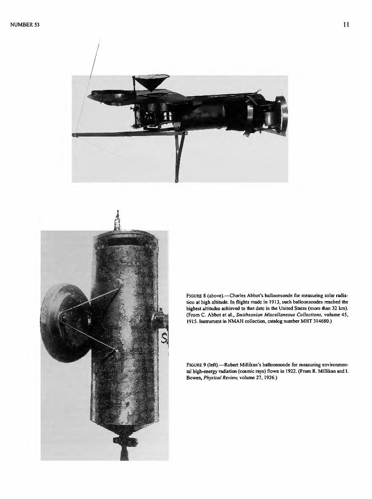
Charles Abbot of the Astrophysical Observatory of the Smithsonian Institution to measure solar radiation at high altitudes (Abbot et al., 1915:1-26). Abbot's work is noteworthy not only because of its scientific results but also because it demonstrated that the existing unmanned balloon technology was capable of lofting payloads to very high altitudes.
In designing his balloonsonde, Abbot adopted the photographic technique pioneered by Baume-Pluvinel. In Abbot's device (Figure 8), a clockwork drive rotated a drum and also
briefly opened the shutter of a slit-like aperture in the housing of the drum. Light, which passed through the aperture, impinged on photographic film on the inner surface of the drum. At the same time the aperture was partly covered by the mercury of a thermometer that rose or fell, depending upon the temperature of an attached disk pyrheliometer. Thus, the length of the aperture image recorded on the film measured the disk temperature, which was a function of the solar radiation. In order to obtain a simultaneous measurement of pressure, the image made by a barometer recording arm also was projected onto the film, a la Baume-Pluvinel.
Abbot used the multiple-balloon recovery technique that had been introduced by Hergesell, which had become the preferred method for use with costly, specialized balloonsondes. Abbot intended to loft his balloonsondes to the highest possible altitudes so as to maximize the reliability of extrapolating the measured value of solar radiation to the value that existed outside the blanket of air surrounding the earth. He used special rubber balloons that were designed and made by a company in Russia, which had produced balloons capable of reaching extremely high altitudes and which had produced most of the sounding balloons used in Europe prior to World War I (Abbott et al, 1915).
Abbot constructed and flew five balloonsondes of this type, at Avalon, California, and Fort Omaha, Nebraska, in 1913— 1914. One flight not only obtained useful data on solar radiation, but also set an altitude record for an unmanned balloon in the United States (32,643 meters) (Abbott et al., 1915). This altitude was extraordinary for that era. Balloons capable of reaching this height generally were not available until after World War II. The Russian firm that made these rubber balloons did not survive World War I; indeed, even its name is unknown.3 Thus, the secret of processing the rubber to increase its stretchability and its resistance to chemical attack by the relatively high concentration of ozone above 25 kilometers also was lost. (Present-day high-altitude balloons are made of ozone-resistant plastic.)
The disappearance of the Russian firm created a serious problem for researchers. For example, in 1919, when Robert Millikan, an American physicist and future Nobel Laureate, constructed a balloonsonde capable of measuring environmental, high-energy radiation (later called cosmic rays) above 25 kilometers, he had great trouble finding suitable balloons (Millikan, 1950:210). He did not obtain usable balloons from a United States manufacturer until 1921, but these still were incapable of reaching the desired altitude.3 Millikan later designed a payload that was capable of measuring the intensity of ionizing radiation as a function of altitude to a height of 32 kilometers (Figure 9). Like the instruments of Baume-Pluvinel and Abbot, Millikan's balloonsondes used a photographic method of data storage to record simultaneously the output of a small, bifilar electrometer and the movement of the arm of a pressure sensor (Millikan and Bowen, 1926). These balloonsondes were flown in 1922, and, although the data were useful, the maximum altitude achieved (15.5 kilometers) was far lower
NUMBER 53 11
m
*
M. ^ ^ ^ ^ ^ f i g t e :;.JlMWWMk..s..-
1 1 |
. v i j ^ ^ K ; : 1 > ;Tffi MPffi****-:'"-j '• '^^^^^^^ ^
j p 4 ^B &sSaBBK&r£idtim- 1111111111 ':'v
, 1 | ^ \ I
"~*-l M
11
,4?
|S|
< ? ^
. ;fc
WmL> 1 pffa
\S|^^H Wmk \ AM$$& i
W&ffi&gm:, "Wmmk ' ^•nmmmmW: s^<mm8§m •
FIGURE 8 (above).—Charles Abbot's balloonsonde for measuring solar radiation at high altitude. In flights made in 1913, such balloonsondes reached the highest altitudes achieved to that date in the United States (more than 32 km). (From C. Abbot et al., Smithsonian Miscellaneous Collections, volume 45, 1915. Instrument in NMAH collection, catalog number MHT 314680.)
FIGURE 9 (left).—Robert Millikan's balloonsonde for measuring environmental high-energy radiation (cosmic rays) flown in 1922. (From R. Millikan and I. Bowen, Physical Review, volume 27, 1926.)
12 SMITHSONIAN STUDIES IN HISTORY AND TECHNOLOGY
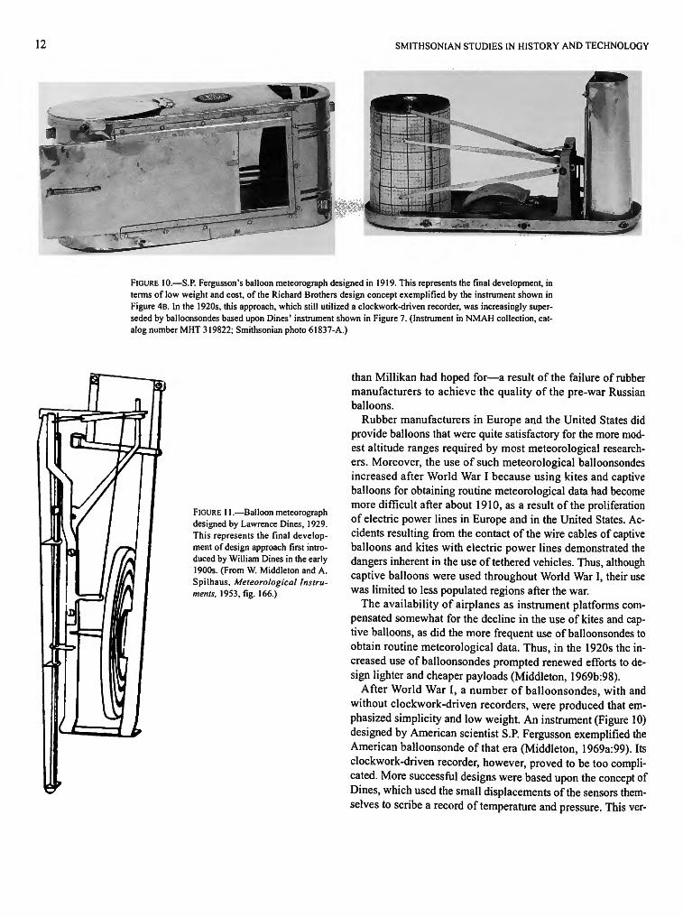
FIGURE 10.—S.P. Fergusson's balloon meteorograph designed in 1919. This represents the final development, in terms of low weight and cost, of the Richard Brothers design concept exemplified by the instrument shown in Figure 4B. In the 1920s, this approach, which still utilized a clockwork-driven recorder, was increasingly superseded by balloonsondes based upon Dines' instrument shown in Figure 7. (Instrument in NMAH collection, catalog number MHT 319822; Smithsonian photo 61837-A.)
FIGURE 11.—Balloon meteorograph designed by Lawrence Dines, 1929. This represents the final development of design approach first introduced by William Dines in the early 1900s. (From W. Middleton and A. Spilhaus, Meteorological Instruments, 1953, fig. 166.)
than Millikan had hoped for—a result of the failure of rubber manufacturers to achieve the quality of the pre-war Russian balloons.
Rubber manufacturers in Europe and the United States did provide balloons that were quite satisfactory for the more modest altitude ranges required by most meteorological researchers. Moreover, the use of such meteorological balloonsondes increased after World War I because using kites and captive balloons for obtaining routine meteorological data had become more difficult after about 1910, as a result of the proliferation of electric power lines in Europe and in the United States. Accidents resulting from the contact of the wire cables of captive balloons and kites with electric power lines demonstrated the dangers inherent in the use of tethered vehicles. Thus, although captive balloons were used throughout World War I, their use was limited to less populated regions after the war.
The availability of airplanes as instrument platforms compensated somewhat for the decline in the use of kites and captive balloons, as did the more frequent use of balloonsondes to obtain routine meteorological data. Thus, in the 1920s the increased use of balloonsondes prompted renewed efforts to design lighter and cheaper payloads (Middleton, 1969b:98).
After World War I, a number of balloonsondes, with and without clockwork-driven recorders, were produced that emphasized simplicity and low weight. An instrument (Figure 10) designed by American scientist S.P. Fergusson exemplified the American balloonsonde of that era (Middleton, 1969a:99). Its clockwork-driven recorder, however, proved to be too complicated. More successful designs were based upon the concept of Dines, which used the small displacements of the sensors themselves to scribe a record of temperature and pressure. This ver-
NUMBER 53 13
FIGURE 12.—Jaumotte meteorograph of 1931. This is an example of a European instrument that was strongly influenced by the Dines design. (Instrument in NMAH collection, catalog number MHT 319823; Smithsonian photo 48467-E.)
sion strongly influenced the design of meteorological balloonsondes from the early 1900s through the 1930s (Middleton and Spilhaus, 1953:231).
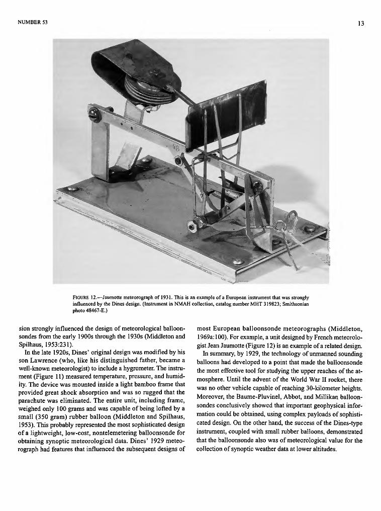
In the late 1920s, Dines' original design was modified by his son Lawrence (who, like his distinguished father, became a well-known meteorologist) to include a hygrometer. The instrument (Figure 11) measured temperature, pressure, and humidity. The device was mounted inside a light bamboo frame that provided great shock absorption and was so rugged that the parachute was eliminated. The entire unit, including frame, weighed only 100 grams and was capable of being lofted by a small (350 gram) rubber balloon (Middleton and Spilhaus, 1953). This probably represented the most sophisticated design of a lightweight, low-cost, nontelemetering balloonsonde for obtaining synoptic meteorological data. Dines' 1929 meteorograph had features that influenced the subsequent designs of
most European balloonsonde meteorographs (Middleton, 1969a: 100). For example, a unit designed by French meteorologist Jean Jaumotte (Figure 12) is an example of a related design.
In summary, by 1929, the technology of unmanned sounding balloons had developed to a point that made the balloonsonde the most effective tool for studying the upper reaches of the atmosphere. Until the advent of the World War II rocket, there was no other vehicle capable of reaching 30-kilometer heights. Moreover, the Baume-Pluvinel, Abbot, and Millikan balloonsondes conclusively showed that important geophysical information could be obtained, using complex payloads of sophisticated design. On the other hand, the success of the Dines-type instrument, coupled with small rubber balloons, demonstrated that the balloonsonde also was of meteorological value for the collection of synoptic weather data at lower altitudes.

14 SMITHSONIAN STUDIES IN HISTORY AND TECHNOLOGY
The major problem of the balloonsonde, in both high-altitude geophysical research and in the collection of meteorological data at low altitudes, was payload recovery. The probability of recovery was low in some unpopulated locations (such as the Arctic), and the loss of the data from one-of-a-kind payloads in special research flights was very costly. For relatively inexpensive meteorological balloonsondes that were launched in quantity, the loss of the data from an occasional lost payload was not serious, but the considerable lapse of time between the flight and recovery of the data significantly reduced the usefulness of balloonsondes in weather forecasting.
In the late 1920s, the advent of the radiosonde was a "natu
ral" development of the balloonsonde whose evolution was determined mostly by advances in radio technology; that is, the necessary theoretical groundwork for the radiosonde existed long before such an instrument was produced. However, the possibility of linking balloon-borne sensors to a ground station via radio depended upon the development of transmitter components of suitable size, weight, power, and ability to survive the temperatures and pressures to which balloon payloads were subjected. Indeed, the first radiosondes utilized principles of telemetering by wire that had been understood more than three quarters of a century earlier, and they embodied principles of radio that had been well understood for almost two decades.
2. Preradio Telemetering, 1842-1894
The development of the electromagnetic telegraph progressed rapidly after about 1830, and by 1840 many miles of circuits had been built. At that time it was apparent to scientists that there were at least two ways in which the telegraph could be applied to problems of meteorological data gathering. First, data already recorded could be transmitted very quickly to centers for analysis and archival storage. Second, and more intriguing, the instruments themselves could be connected by telegraph wire to deliver their data directly to the place where it would be used. Both applications came into use fairly quickly, but the second approach presented difficulties (Borden and Thynell, 1948).
Prior to 1840, information transmitted by telegraph had to originate in a discretely coded or symbolic form. In normal (nonmeteorological) message transmission, this form was standard language, including numerals and punctuation marks. Different schemes of representing alphabets and numerals were available, such as the Morse-Vail code, but these were only translations of the original symbols. They were, nevertheless, still discrete symbols and were easily sent over the telegraph as such.
Meteorological data presented a fundamentally different requirement. Data from the thermometer, barometer, and wind-registering devices were not discrete but, rather, were continuous or analog in form. Scratching this data on a smoked drum or inking it on paper was simple as long as the drum or paper was in direct contact with the sensing device itself. Indeed, these, or closely allied methods, were the universal recording system for all early meteorographs. Transmitting such analog data to a remote location, without an observer to first "read" the data and convert it to discrete symbols, was a very difficult problem.
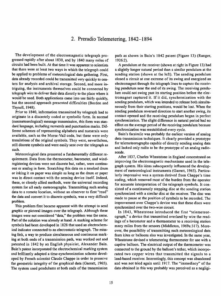
This problem first became apparent with the attempt to send graphic or pictoral images over the telegraph. Although these images were not considered "data," the problem was the same. Part of the solution was already at hand. A marking scheme for symbols had been developed in 1828 that used an electrochemical indicator connected to an electrostatic telegraph. The missing link, a way to produce simultaneous and continuous marking at both ends of a transmission path, was worked out and patented in 1842 by an English physicist, Alexander Bain. Bain's patent incorporated the electrochemical marking system and brilliantly adapted a time-synchronization scheme developed by French scientist Claude Chappe in order to preserve the geometric integrity of the graphical data (Garratt, 1965). The system used pendulums at both ends of the transmission
path as shown in Bain's 1842 patent (Figure 13) (Ranger, 1926:2).
A pendulum at the receiver (shown at right in Figure 13) had a slightly longer natural period than a similar pendulum at the sending station (shown at the left). The sending pendulum closed a circuit at one extreme of its swing and energized an electromagnet through the telegraph lines to capture the receiving pendulum near the end of its swing. The receiving pendulum could not swing past its starting position before the electromagnet captured it. If it did, synchronization with the sending pendulum, which was intended to release both simultaneously from their starting positions, would be lost. When the sending pendulum reversed direction to start another swing, its contact opened and the receiving pendulum began in perfect synchronization. The slight difference in natural period had no effect on the average period of the receiving pendulum because synchronization was reestablished every cycle.
Bain's facsimile was probably the earliest version of analog data-transmission techniques. It clearly provided a prototype for telemeteorographs capable of directly sending analog data and lacked only radio to be the prototype of an analog radiosonde.
After 1837, Charles Wheatstone in England concentrated on improving the electromagnetic mechanisms used in the telegraph system. His ideas subsequently influenced the development of meteorological instruments (Garratt, 1965). Particularly impressive was a system derived from Chappe's time coding, which removed most of the burden from the operator for accurate interpretation of the telegraph symbols. It consisted of a continuously stepping disc at the sending station synchronized with a similar disc at the receiver. The disc was made to pause at the position of symbols to be recorded. The improvement over Chappe's device was that these discs were synchronized over the two-wire circuit.
In 1843, Wheatstone introduced the first "telemeteor-ograph," a device that transmitted overland by wire the readings of a barometer and a thermometer to a receiving station many miles from the sensors (Middleton, 1969a:317). Moreover, the possibility of transmitting such meteorological data from kites or balloons also was investigated. In the same year, Wheatstone devised a telemetering thermometer for use with a captive balloon. The electrical output of the thermometer was connected to the ground by the balloon's tether, which incorporated two copper wires that transmitted the signals to a land-based receiver. Interestingly, this concept was abandoned and was not tried again until 1917. The "immediacy" of the data obtained in this way probably was perceived as a negligi-
15

16 SMITHSONIAN STUDIES IN HISTORY AND TECHNOLOGY
-s'rs
FIGURE 13.—Alexander Bain's two-pendulum concept. This is a reproduction of the diagram in Bain's 1842 patent. (From R. Ranger, Proceedings of the Institute of Radio Engineers, volume 14, 1926.)
ble improvement because tethered kites and balloons carrying self-recording instruments could be cranked down within minutes of reaching their maximum altitude, thus allowing the timely retrieval of data. The use of overland telegraphy links to sensors in remote locations also was developed in the mid-nineteenth century.
About 1868, a Dutch professor, F. van Rysselberghe, developed a meteorograph, using the earlier ideas of Wheatstone and others. It converted readings of pressure, temperature, and wind speed to markings on a rotating drum. In 1874, another Dutch scientist, E.H. von Baumhauer, published a design suitable for telemeteorography from a balloon or kite, similar to van Rysselberghe's, which also produced markings on a smoothly rotating drum (Middleton, 1969a:318-321). Transmission of markings between similar drums required near synchronization of rotation, and von Baumhauer proposed the use of a signal over telegraph wire to start them simultaneously. Subsequent synchronization relied upon constant speed of the individual drums; an "open-loop" method identical in principle to the electrostatic telegraph system that Chappe had devised almost a hundred years earlier.
A deficiency of von Baumhauer's telemeteorograph was that the rotation speed of one clock- or motor-driven drum could not be made perfectly equal to another, given the technology of that time. Thus the receiving drum would eventually drift out of step with the transmitter. Working to improve performance of the telemeteorograph, H. OUand, a Dutch instrument maker, built an elaborate system in 1877, using a sensor design similar to von Baumhauer's drum and incorporating a pendulum synchronization system identical in principle to Bain's (Middleton, 1969a:324). Periodic synchronization of the rotating drums greatly shortened the period during which they were required to maintain constant speed and thus allowed satisfactory operation for an indefinite period. Olland personally knew von Baumhauer and, at his suggestion, used some of his ideas. It is unclear, however, if Olland was familiar with Bain's work, so he may have "reinvented" Bain's two-pendulum concept. The overall scheme became known as the "Olland Cycle" (Middle-ton, 1969a:324) as used in later instruments, including radiosondes, but it clearly incorporated ideas of Bain, von Baumhauer, and van Rysselberghe.
This principle is extremely effective and inherently simple. It is so attractive that it has been used, in appropriate technology,

NUMBER 53 17
$ = *
/"SN
V*/ / J ^ \
( - J
/Z?\
f ~^^m$ VB-V'
-*• J"
/^"•Af
-' V
FIGURE 14.—"Digital" transmission telemeteorograph designed by Luigi Cerebotani and Albert Silbermann. (From German Patent Number 93032, 1896.)
li SMITHSONIAN STUDIES IN HISTORY AND TECHNOLOGY
by virtually every development in data communications up to the present.4 The concept, reduced to its most basic form, involves the entrainment of one oscillator by another, where the degree of stability of the chosen oscillators is sufficient for the purpose at hand. In communications, unsynchronized timekeeping devices with stable, short-term periods are used at sending and receiving ends of a path. The sending timekeeper resets the receiving timekeeper periodically by some means to a specific phase point to achieve long-term synchronization.
A modern example is the mechanical teletype developed for text transmission, which evolved into a universal system of asynchronous data transmission between computers. In these systems, a signal is transmitted instructing the receiver to begin recognizing a prearranged number of elements (bits) of a fixed-length message at a predetermined rate. After the prearranged number of elements, the receiver waits for a signal indicating that the sending interval is over, then waits for a new start signal and the cycle repeats.
The only other synchronization scheme in common use for data telemetry is one in which timing information is contained within the overall symbol stream. Timing information modulates the transmitted signal orthogonally to the data so that both can be separated at the receiver. This technique originated after 1940 and did not come into use with meteorological data until the beginning of rocket telemetry. It has never seen significant use in mass-produced balloon-borne radiosondes.
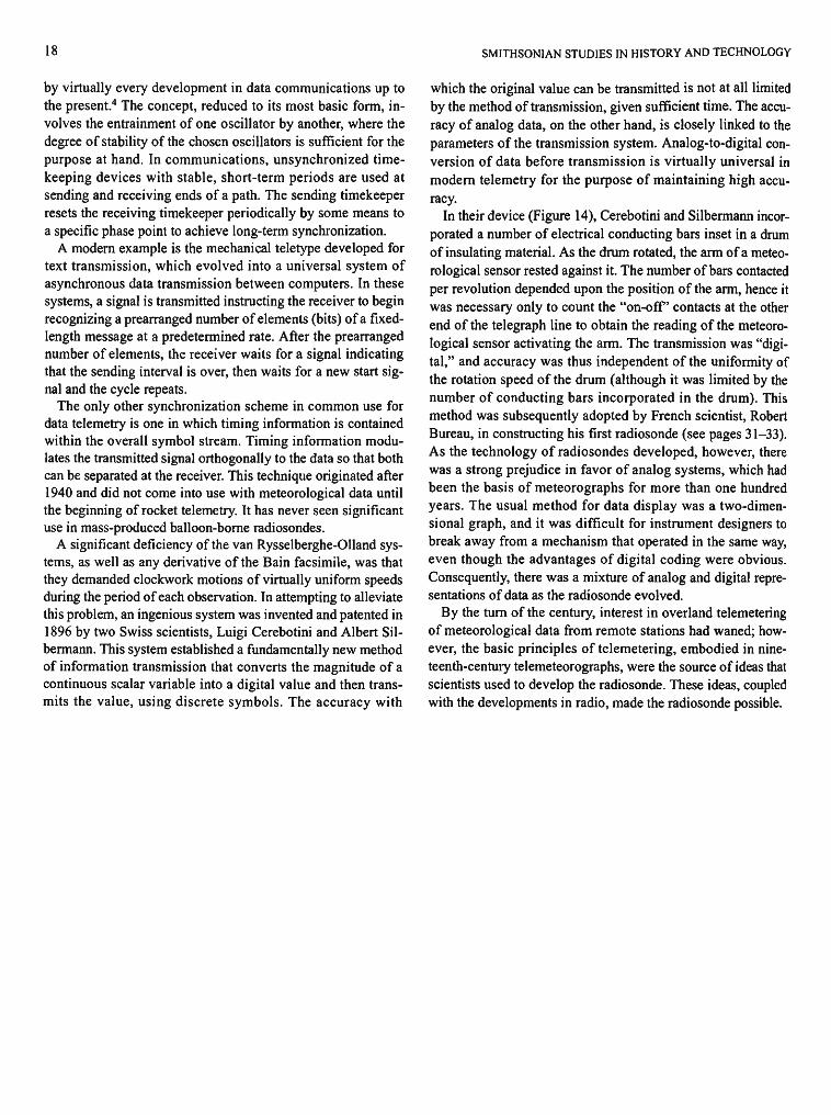
A significant deficiency of the van Rysselberghe-Olland systems, as well as any derivative of the Bain facsimile, was that they demanded clockwork motions of virtually uniform speeds during the period of each observation. In attempting to alleviate this problem, an ingenious system was invented and patented in 1896 by two Swiss scientists, Luigi Cerebotini and Albert Sil-bermann. This system established a fundamentally new method of information transmission that converts the magnitude of a continuous scalar variable into a digital value and then transmits the value, using discrete symbols. The accuracy with
which the original value can be transmitted is not at all limited by the method of transmission, given sufficient time. The accuracy of analog data, on the other hand, is closely linked to the parameters of the transmission system. Analog-to-digital conversion of data before transmission is virtually universal in modern telemetry for the purpose of maintaining high accuracy.
In their device (Figure 14), Cerebotini and Silbermann incorporated a number of electrical conducting bars inset in a drum of insulating material. As the drum rotated, the arm of a meteorological sensor rested against it. The number of bars contacted per revolution depended upon the position of the arm, hence it was necessary only to count the "on-off' contacts at the other end of the telegraph line to obtain the reading of the meteorological sensor activating the arm. The transmission was "digital," and accuracy was thus independent of the uniformity of the rotation speed of the drum (although it was limited by the number of conducting bars incorporated in the drum). This method was subsequently adopted by French scientist, Robert Bureau, in constructing his first radiosonde (see pages 31-33). As the technology of radiosondes developed, however, there was a strong prejudice in favor of analog systems, which had been the basis of meteorographs for more than one hundred years. The usual method for data display was a two-dimensional graph, and it was difficult for instrument designers to break away from a mechanism that operated in the same way, even though the advantages of digital coding were obvious. Consequently, there was a mixture of analog and digital representations of data as the radiosonde evolved.
By the turn of the century, interest in overland telemetering of meteorological data from remote stations had waned; however, the basic principles of telemetering, embodied in nineteenth-century telemeteorographs, were the source of ideas that scientists used to develop the radiosonde. These ideas, coupled with the developments in radio, made the radiosonde possible.
3. Radio Telemetry, 1895-1929
By 1850, the telegraph had become firmly established as a means of transmission of language and data; however, there already was frustration with the difficulty and expense of installing wires. It had been known since the work of Faraday and Henry that electric currents could produce effects in a circuit not connected by wires to the source of the current. The phenomenon, called mutual induction, had fascinated experimenters in Europe and America as a possibility for creating a wireless version of the telegraph. The range of induction in the 1850s was disappointing, however, only a few meters. Although induction transmission was extended to a few kilometers by the 1890s, it still did not offer a workable means of wireless communication (Blake, 1928:282-284).
Between 1865 and 1886, many experimenters demonstrated the existence of propagating electromagnetic radiation. A great deal of this work was unpublished or was reported in popular literature, rather than in scientific journals. A few articles described results that probably were caused by radiation, but the phenomenon was poorly understood and was not well explained by the investigators (Thomson, 1853).
The early confusion between induction and radiation is not difficult to understand. Electromagnetic induction is related to radiation, as explained by a theory advanced by James Clerk Maxwell (Maxwell, 1865). However, Maxwell's theory remained beyond the ken of most investigators until Heinrich Hertz, who, working with a firm understanding of mathematics and Maxwell's equations, first conducted energy from a spark discharge by wire to a metal loop containing a small gap that would spark after the discharge (Hertz, 1888). Hertz then set up an identical loop at a distance and observed that it sparked at the same time. He subsequently proved the wave nature of this interaction by carefully demonstrating reflection, refraction, interference, and velocity. Hertz correctly showed that the wavelength was about 25 centimeters. Although his maximum range of transmission was only 19 meters, this was more than 50 wavelengths. The range of transmission, expressed in wavelengths, was more important than just an extension of communication distance. It proved that the signals were indeed radiation and not caused by the induction effect. Maxwell's equations show that the electric field at a distance from a conducted current can have components proportional to wavelength divided by distance, distance squared, and distance cubed. Only the component inversely proportional to distance is associated with self-propagating radiation; the others produce induction effects. By a distance of 50 wavelengths from the source, the inverse squared and cubed terms will have essentially disappeared, leaving only the true radiation.
Maxwell's radiation became known in the literature as Hertzian Waves. Experimenters duplicated the work and extended the experiments across greater distances for application to wireless communication. The prospect of a lucrative business in making apparatus to replace wire telegraphy interested both skilled scientists and tinkerers (Blake, 1928). Individuals who used various techniques and who achieved successful results in the period 1887 to 1890 included Edouard Branly, Alexander Popov, Gugliemo Marconi, Nicholas Tesla, Ferdinand Braun, and Sir Oliver Lodge. By 1895, Marconi had shown conclusively that a practical system of wireless signalling was possible. By 1896, Popov and Marconi had demonstrated wireless systems with a range of about 10 kilometers. The next year Marconi, who sought commercial success, had reached a range of 70 kilometers. (In 1909, Marconi and Braun, whose "spark-less antenna system" represented a significant improvement, shared a Nobel prize for the development of wireless telegraphy.)
At the turn of the century, wire telegraphy spanned thousands of miles in Europe and America. Wireless offered the possibility of communication across long distances without the costly networks of wire. This was a compelling goal, and enormous amounts of money and effort were dedicated to its accomplishment. There was a rapid progression to large, powerful apparatus that seemed to be the means of obtaining greater range. Use of such huge equipment to return meteorological data from aloft appeared not only impractical but foolish, so the transition from balloonsondes to radiosondes was not seriously considered at that time.
The brute-force style of transmission apparatus was confirmed by contemporary quantitative theory. Large antennas created higher-amplitude radiation fields and consequently larger signals at the receiver. The wavelength at which these large antennas absorbed energy (from impulse or spark excitation) and radiated efficiently was proportional to their dimensions.5 Consequently, long wavelengths were necessary for communications, on the order of the antenna dimensions. Empirical studies undertaken by Hertz (1888) showed that range was proportional to power and antenna size, as predicted by Maxwell's theory. Absorption of the waves increased with distance and appeared to become virtually complete below about 200 meters, an added obstacle to shorter wavelengths and smaller, lighter equipment.
In the years after Hertz's work, a major obstacle to greater range, in addition to power and propagation, was the sensitivity of the receiving apparatus. At the outset it was obvious that a receiver that depended upon the display of sparks was imprac-
19

20 SMITHSONIAN STUDIES IN HISTORY AND TECHNOLOGY
tical for use at distances needed for communication. A solution was at hand, however, even before Hertz's work, in a scheme used by Hughes for induction receiving in the 1870s (Hughes, 1878). He had utilized a receiving circuit that passed current through an assembly of carbon powder originally developed as a sound-to-current transducer for the emerging technology of sound transmission over telegraph wires. Various experimenters (see Howeth, 1963:15-23) had demonstrated properties of this type of device, consisting of an evacuated tube of metal filings between silver electrodes that would serve as a sensitive detector for wireless radiation. Called the "coherer," it was perfected by two American engineers, Forbes and Lodge, between 1892 and 1894 (Lodge, 1908:32-56). This device quickly became the standard wireless detector, with virtually no competition until the invention of Fessenden's electrolytic detector in 1903.
Fundamental improvements were made in wireless technology that extended transmission range (but did nothing to reduce the size of the required equipment) between 1897 and 1900. In order to improve conversion of power into radiation, Lodge used inductance and capacitance to make the antenna circuit resonant at the wavelength desired for transmission. In addition to improving efficiency by better matching of impedance between the antenna and generator, this substantially narrowed the range of wavelengths in the radiation. When Marconi applied similar tuning to the antenna circuit of a receiver, the overall effect was dramatic. He achieved the first transatlantic contact on 12 December 1901, at about 1000 meters wavelength. Further progress in narrowing the bandwidth of transmissions followed shortly, with development of the Poulsen arc and the Fessenden-Alexanderson alternators. Instead of the relatively inefficient process of generating a wide band of wavelengths by spark discharge and selecting only part of this spectrum by a resonant circuit, these devices generated oscillations more-or-less in the wavelength range desired. An additional reason for improved efficiency was that radio-frequency energy generated by spark transmitters was discontinuous, whereas alternators generated continuous undamped waves. The time-averaged power available for transmitting was therefore greater. Reactive parameters of the antenna circuit still influenced efficiency of energy conversion to radiation, but wavelength was fairly well defined and could be selected for favorable propagation (Morecroft, 1921:511-513).
In 1904, the first developments occurred that would lead to the construction of small radio transmitters that operated at wavelengths suitable for meteorological data transmission from balloon-borne instruments. The beginning, however, lies not with transmission but with reception. J.A. Fleming, who earlier had worked with Marconi to establish transatlantic wireless, used the "Edison effect" to achieve high sensitivity as a detector, replacing Branly's coherer. The Edison effect, which Edison had reported in 1883, refers to the phenomenon of electric current flow through an evacuated tube containing electrodes. By 1901, physicists understood this effect, and Fleming
used it to "rectify" or convert the radio frequencies picked up by a receiver to direct current in a headphone or galvanometer (Chaffee, 1933:1-16).
Fleming's achievement quickly led other investigators to use these "vacuum tubes." In 1906, Lee de Forest showed that by adding a third electrode, current flow between the other two electrodes could be controlled, using virtually no power (de Forest, 1906). Still, probably as a result of Fleming's lead, early work on application of these tubes was concentrated on improving the sensitivity of radio reception. Unintentionally, this approach was fortunate for eventual application to meteorological data trans-mission because it fostered development of small, low-powered circuits before the obsession with high-energy transmission could dominate the entire effort of engineers. In fact, much of the early work with tubes, called "audions," was devoted to amplification of telephone communications over wire; also a comparatively low-power application (de Forest, 1906).
From 1905 to 1915, progress in radio technology was steady but not spectacular. After 1915, the demands of the military services fighting in World War I gave impetus to the development of more efficient tubes and circuits. For example, in 1916, the first use of aircraft radios had occurred (Figure 15), although the radios still were too large to be adapted for balloonsonde use (Tyne, 1977:117). There was intense competition for financial rights regarding inventions within the emerging business of radio, and patent litigation was common. Not until the latter part of that period did developments in applied technology reach a point that promised help for scientists attempting to send data directly from a balloon carrying meteorological instruments.
There was no lack of interest in this application. German science historian Paul Beelitz (1954:67) reported a private communication from E.F. Herath, written in 1950, indicating that Herath and other German meteorologists, Max Robitzsch and Alfred Wegner, considered using balloon-borne radio transmitters in the summer of 1914. The vacuum tubes that were available, however, such as the de Forest audions, were poorly evacuated, which rendered them unpredictable in circuits. (Two American engineers, Langmuir and Arnold, succeeded in building much-improved high-vacuum tubes in 1912-1913 at the General Electric and AT&T laboratories, but they did not reach production for several years (Tyne, 1977:133-157)). This defect, together with fragile construction, made vacuum tubes unsuitable for service in the relatively hostile environment to which balloons ascend. Another difficulty was that, in 1914, the only circuit design that could make a balloon-borne transmitter practical, the continuous wave oscillator, was still in its infancy and was not widely known.
This situation did not deter experimentation with radio-frequency energy to get data from balloons aloft. Pierre Idrac in France, and Herath and Robitzsch in Germany, in separate experiments during 1917, used radio-circuit techniques to send data down the wire of a tethered kite. No doubt some slight ra-

NUMBER 53 21
*
1916 FIGURE 15.—Gugliemo Marconi's air-to-ground radio, circa 1916. (From a Marconi Instrument Company advertising brochure mailed to the electronics industry in the spring of 1987.)
diation did occur in the process, but no attempt to measure this was recorded (Middleton, 1969a:276).
Early in 1917, Herath and Robitzsch produced a device in which a contact on a revolving drum touched a stylus of the sensor and energized the primary of a small spark coil (Middle-ton, 1969a: 103). The secondary of this coil was paralleled with a capacitor and spark gap. One side of this broadly tuned circuit was connected to the steel tether of the kite. Detection was achieved by a telephone receiver connected to the kite. Data coding was analog by time interval. The stylus-drum contact was closed once each revolution of the drum at a fixed point on the drum, regardless of stylus position. It was closed again at a time dependent on the position of the stylus, thereby converting stylus position into a time interval. As long as the signal from both closings was clearly received, the scheme was self-calibrating and precise to about one degree centigrade for temperature readings.
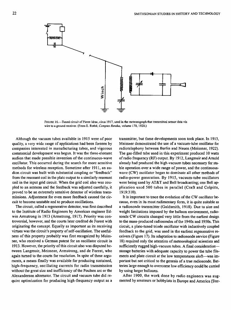
A more elaborate experiment was conducted in September of 1917, in France (Rome, 1936:278). Pierre Idrac used a self-interrupting spark gap, or "buzzer," in the balloon to excite a parallel-tuned circuit (Figure 16). The buzzer was energized by a contact driven from the meteorological sensor. The balloon
tether again served as an electrical conductor for the radio-frequency signals. Idrac significantly improved reception by using a parallel-tuned circuit coupled inductively to the tether at the ground. A rectifier and telephone receiver across this tuned circuit completed the receiving circuit. Idrac pointed out an important feature of this scheme that derived from the radio-frequency circuits: by using multiple transmitters tuned to different frequencies, the same tether could conduct data simultaneously from several sensors without interference. On the ground a tuned receiver could separate these signals. Idrac also had a capacitor sensitive to temperature. This would code the data into a frequency that could be measured on the ground. This technique subsequently was used by some radiosonde developers.
The research of Herath, Robitzsch, and Idrac anticipated developments in radio technology that would lead to the balloon-borne radio transmission of meteorological data. They already were working with the same radio-frequency energy and circuit techniques that drove wireless telegraphy. It was only the lack of small, rugged, radio-frequency oscillators that kept them from making this innovative transition.
22 SMITHSONIAN STUDIES IN HISTORY AND TECHNOLOGY
FIGURE 16.—Tuned circuit of Pierre Idrac, circa 1917, used in the meteorograph that transmitted sensor data via wire to a ground receiver. (From E. Rothe, Comptes Rendus, volume 170, 1920.)
Although the vacuum tubes available in 1915 were of poor quality, a very wide range of applications had been forseen by companies interested in manufacturing tubes, and vigorous commercial development was begun. It was the three-element audion that made possible invention of the continuous-wave oscillator. This occurred during the search for more sensitive methods for wireless reception. Sometime after 1911, an audion circuit was built with substantial coupling or "feedback" from the resonant coil in the plate output to a similarly resonant coil in the input grid circuit. When the grid coil also was coupled to an antenna and the feedback was adjusted carefully, it proved to be an extremely sensitive detector of wireless transmissions. Adjustment for even more feedback caused the circuit to become unstable and to produce oscillations.
The circuit, called a regenerative detector, was first described to the Institute of Radio Engineers by American engineer Edwin Armstrong in 1913 (Armstrong, 1917). Priority was controversial, however, and the courts later credited de Forest with originating the concept. Equally as important as its receiving virtues was the circuit's property of self-oscillation. The usefulness of this property probably was first recognized by Meiss-ner, who received a German patent for an oscillator circuit in 1913. However, the priority of this circuit also was disputed between Langmuir, Meissner, Armstrong, and de Forest, who again turned to the courts for resolution. In spite of these arguments, a means finally was available for producing sustained, high-frequency, oscillating currents for radio transmission without the great size and inefficiency of the Poulsen arc or the Alexanderson alternator. The circuit and vacuum tube did require optimization for producing high-frequency output as a
transmitter, but these developments soon took place. In 1913, Meissner demonstrated the use of a vacuum-tube oscillator for radiotelephony between Berlin and Nauen (Meissner, 1922). The gas-filled tube used in this experiment produced 10 watts of radio frequency (RF) output. By 1912, Langmuir and Arnold already had produced the high-vacuum tubes necessary for stable operation over a wide range of power, and the continuous-wave (CW) oscillator began to dominate all other methods of radio-power generation. By 1915, vacuum-tube oscillators were being used by AT&T and Bell broadcasting; one Bell application used 500 tubes in parallel (Craft and Colpitts, 1919:310).
It is important to trace the evolution of the CW oscillator because, even in its most rudimentary form, it is quite suitable as a radiosonde transmitter (Goldsmith, 1918). Due to size and weight limitations imposed by the balloon environment, radiosonde CW circuits changed very little from the earliest design to the mass-produced radiosondes of the 1940s and 1950s. This circuit, a plate-tuned triode oscillator with inductively coupled feedback to the grid, was used in the earliest regenerative receivers (Figure 17). Its adaptation to radiosonde service (Figure 18) required only the attention of meteorological scientists and sufficiently rugged high-vacuum tubes. A final consideration— storage batteries with adequate capacity to power the tube filaments and plate circuit at the low temperatures aloft—was important but not critical to the genesis of a true radiosonde. Batteries large enough to overcome low efficiency could be carried by using larger balloons.
After 1900, the work done by radio engineers was augmented by amateurs or hobbyists in Europe and America (Ster-
NUMBER 53 23
V
FIGURE 17.—Circuit by H.J. Round for using a three-electrode valve for beat reception, circa 1913. (From J. Fleming, The Thermionic Valve and Its Development in Radiography and Telegraphy, London, 1919, fig. 112.)
ling, 1928). These enthusiastic individuals with, for the most part, no commercial motives, were highly innovative and did not have the obsession with high power and long wavelength that characterized "professional" radio development. It is essential to include amateur radio technology in the history of radiosonde evolution because it brought about the development and use of low-power transmitting oscillators. In 1917, President Wilson ordered all amateur wireless stations dismantled and all commercial stations turned over to the U.S. Navy. The policy did not, however, halt the hobbyist's valuable contributions to radio science because many took up similar work in government laboratories. Another large group of amateurs contributed to the war effort by serving as wireless operators.
The development of vacuum tubes suitable for operation of a triode CW oscillator as a balloon-borne radiosonde occurred
Cs
•ir-r p
W¥\^ — - H • • *
A-
C£
B+
FIGURE 18.—Tuned plate oscillator circuit used in radiosondes, circa 1934. LI and L2 are coupled to provide feedback for oscillation. Note the similarity to the circuit shown in Figure 17. (From W. Wenstrom, Monthly Weather Review, volume 62, 1934.)
between 1914 and 1918, although the secrecy surrounding such work in World War I obscured the record of developments in vacuum tubes and low-power transmitting oscillators from 1917 through about 1919. Development of vacuum tubes was both retarded by wartime secrecy and, at least regionally, advanced by wartime need for improved field communications. Low-power, battery-operated transmitters, using new, smaller, vacuum tubes, were built for military signaling, and descriptions of them appeared in post-war literature. For example, Meissner (1922:3) described a high-vacuum tube transmitter with 10- to 15-watt output, built by the Telefunken Company in 1915, and indicated that it was "practically the same arrangement as the transmitter used experimentally by the Allies at the end of 1917 on the West Front." A French "R" type high-vacuum tube was patented in 1916 and used in Allied receivers. The filament requirements were 3.7 volts at 500 milliamps, and 75 volts was adequate for the plate supply. These figures were compatible with the battery power supply for a field CW transmitter. The United States began to develop two-way radiotelephone sets shortly after its entry into the war for use on submarine chasers and airplanes. These sets used standardized high-vacuum, oxide-coated, filament tubes and had a simple, field-serviceable design (Tyne, 1977:190-278; Blake, 1928:244-245). Large-scale production of this apparatus was not achieved in time for significant field use in airplanes by the U.S. Army.
Wartime need for small, portable equipment led to interest in shorter wavelengths. The initial reason was that smaller antennas would be more practical and easier to conceal in the field. Smaller antennas, however, required shorter wavelengths to be most efficient. This was a fortuitous development for balloon-borne transmitters because the few hundred meter wavelength of common radiotelegraphy was impractical for a balloon antenna. Initial experiments with shorter wavelengths brought an unexpected result. It was discovered that range

24 SMITHSONIAN STUDIES IN HISTORY AND TECHNOLOGY
FIGURE 19 (right).—Catalog and instruction book for building an apparatus for continuous wave operation, circa 1921. (From Anon., The Radio Industry, New York, 1928, fig. 3.)
FIGURE 20 (below).—Circuit for using a three-electrode Thermion as a generator of oscillations, circa 1919. Coils R and L in the grid and the plate circuits are closely coupled. This circuit, which has remained virtually unchanged, and a Hartley circuit, where the grid is tapped off the plate coil, later became standard radiosonde transmitters. (From J. Fleming, The Thermionic Valve and Its Development in Radiography and Telegraphy, London, 1919, fig. 137.)
RADIO APPARATUS Amateur and Experimental Use
^h INSTRUCTIONS *&r
CONTINUOUS IWMB OPERATION
Radio foi* Corporation WTiLWORTH B1 ffllHNG ~ MBW YORK ClVC
B 400V
r-^W«|l|l| l|l|lf-
-ooosMfJ
\ \ •0005Mfd
r\
•p
F
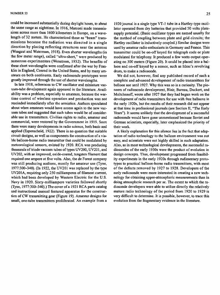
NUMBER 53 25
could be increased substantially during daylight hours, to about the same range as nighttime. In 1916, Marconi made transmissions across more than 1600 kilometers in Europe, on a wavelength of 32 meters. He characterized these as "beam" transmissions because the radiation was directed in a single direction by placing reflecting structures near the antenna (Weagaut and Waterman, 1918). Even shorter wavelengths (in the few meter range), called "ultra-short," were produced by numerous experimenters (Wenstrom, 1932). The benefits of these short wavelengths were confirmed after the war by Franklin in England, Conrad in the United States, and by many amateurs on both continents. Early radiosonde prototypes were greatly improved through the use of shorter wavelengths.
In late 1918, references to CW oscillator and miniature vacuum-tube development again appeared in the literature. Availability was a problem, especially to amateurs, because the wartime control of wireless operation and production was not rescinded immediately after the armistice. Authors speculated about when amateurs would have access again to the new vacuum tubes and suggested that such tubes would be of considerable use in transmitters. Civilian rights to radio, amateur and commercial, were restored by the Government in 1919. Soon there were many developments in radio science, both basic and applied (Espenscheid, 1922). There is no question that suitable circuit designs, as well as components for construction of a viable balloon-borne radio transmitter that could be modulated by meteorological sensors, existed by 1920. RCA was producing thousands of triode vacuum tubes of types UV200, UV201, and UV202, with an improved, oxide-coated, tungsten filament that required one ampere at five volts. Also, the de Forest company was still producing audions, mostly for amateur use (Tyne, 1977:300-340). (In 1922, the UV201 was replaced by the type UV201A, requiring only 250 milliamperes of filament current, which had been developed by Western Electric for the U.S. Navy in 1920. Sixty-milliampere varieties followed shortly (Tyne, 1977:300-340).) The cover of a 1921 RCA parts catalog and instructional manual featured apparatus for the construction of CW transmitting gear (Figure 19). Amateur designs for small, one-tube transmitters proliferated. An example from a
1920 journal is a single type VT-1 tube in a Hartley-type oscillator operated from dry batteries that provided 50 volts plate-supply potential. (Basic oscillator types are named usually for the method of coupling between plate and grid circuits; the Hartley oscillator is inductively coupled.) Similar designs were used by amateur radio enthusiasts in Germany and France. This transmitter could be on-off keyed for telegraph code or plate modulated for telephony. It produced a few watts output operating on 300 meters (Figure 20). It could be placed into a balloon and on-off keyed by a sensor, such as Idrac's revolving drum, to make a radiosonde.
We did not, however, find any published record of such a complete and advanced development of radio transmitters for balloon use until 1927. Why this was so is a curiosity. The pioneers of radiosonde development, Blair, Bureau, Duckert, and Moltchanoff, wrote after 1927 that they had begun work on the development of radio transmitters for use with free balloons in the early 1920s, but the results of their research did not appear at that time in professional journals (see Section II, "The Early Years"). It seems unlikely that the development of a successful radiosonde would have gone unmentioned because Soviet and German scientists, especially, later emphasized the priority of their work.
A likely explanation for this silence lies in the fact that adaptation of radio technology to the balloon environment was not easy, and scientists were not highly skilled in such adaptation. Also, as in most technological developments, the successful radiosondes of the early 1930s were the product of evolution in design concepts. Thus, development progressed from feasibility experiments in the early 1920s through rudimentary prototypes to practical balloon-borne radio transmitters, with most of the defects removed by 1927 to 1928. Developers of the early radiosonde were more interested in creating a new technology for obtaining upper-atmospheric measurements than in doing atmospheric research per se. The extent to which the radiosonde developers were able to utilize directly the relatively mature radio technology of the period from 1920 to 1929 is very difficult to determine. It is possible, however, to trace this evolution from the fragmentary evidence in the literature.
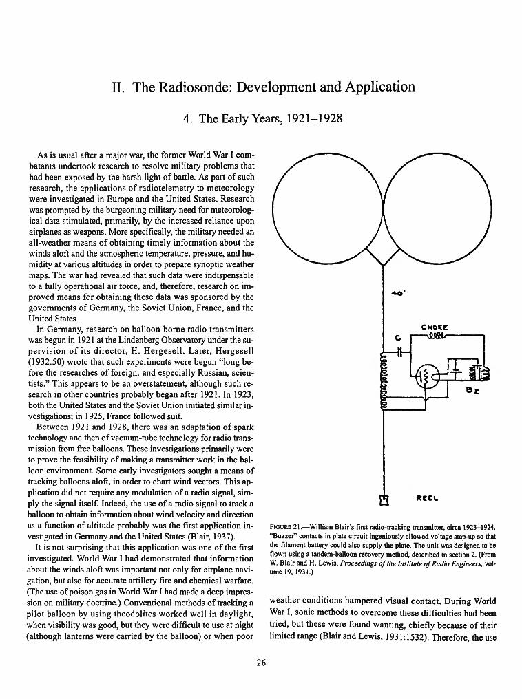
II. The Radiosonde: Development and Application
4. The Early Years, 1921-1928
As is usual after a major war, the former World War I combatants undertook research to resolve military problems that had been exposed by the harsh light of battle. As part of such research, the applications of radiotelemetry to meteorology were investigated in Europe and the United States. Research was prompted by the burgeoning military need for meteorological data stimulated, primarily, by the increased reliance upon airplanes as weapons. More specifically, the military needed an all-weather means of obtaining timely information about the winds aloft and the atmospheric temperature, pressure, and humidity at various altitudes in order to prepare synoptic weather maps. The war had revealed that such data were indispensable to a fully operational air force, and, therefore, research on improved means for obtaining these data was sponsored by the governments of Germany, the Soviet Union, France, and the United States.
In Germany, research on balloon-borne radio transmitters was begun in 1921 at the Lindenberg Observatory under the supervision of its director, H. Hergesell. Later, Hergesell (1932:50) wrote that such experiments were begun "long before the researches of foreign, and especially Russian, scientists." This appears to be an overstatement, although such research in other countries probably began after 1921. In 1923, both the United States and the Soviet Union initiated similar investigations; in 1925, France followed suit.
Between 1921 and 1928, there was an adaptation of spark technology and then of vacuum-tube technology for radio transmission from free balloons. These investigations primarily were to prove the feasibility of making a transmitter work in the balloon environment. Some early investigators sought a means of tracking balloons aloft, in order to chart wind vectors. This application did not require any modulation of a radio signal, simply the signal itself. Indeed, the use of a radio signal to track a balloon to obtain information about wind velocity and direction as a function of altitude probably was the first application investigated in Germany and the United States (Blair, 1937).
It is not surprising that this application was one of the first investigated. World War I had demonstrated that information about the winds aloft was important not only for airplane navigation, but also for accurate artillery fire and chemical warfare. (The use of poison gas in World War I had made a deep impression on military doctrine.) Conventional methods of tracking a pilot balloon by using theodolites worked well in daylight, when visibility was good, but they were difficult to use at night (although lanterns were carried by the balloon) or when poor
CHOKE, C I vflUfilr
a RCCW
FIGURE 21.—William Blair's first radio-tracking transmitter, circa 1923-1924. "Buzzer" contacts in plate circuit ingeniously allowed voltage step-up so that the filament battery could also supply the plate. The unit was designed to be flown using a tandem-balloon recovery method, described in section 2. (From W. Blair and H. Lewis, Proceedings of the Institute of Radio Engineers, volume 19, 1931.)
weather conditions hampered visual contact. During World War I, sonic methods to overcome these difficulties had been tried, but these were found wanting, chiefly because of their limited range (Blair and Lewis, 1931:1532). Therefore, the use
26

NUMBER 53 27
FIGURE 22.—First transmitter operated in the stratosphere. The quarter-wave antenna measured 10.5 meters in length. It was suspended by balloons, and a transmitter hung at its end. With batteries, the entire assembly weighed 2.7 kilograms. Power consumption was four watts, and radiated power probably did not exceed one watt. From left to right are the filament battery, the vertical-axis keying windmill, and the transmitter (including plate batteries, inductances, and tubes). The unit was constructed entirely from commercially available parts. (From R. Bureau, La Meteorologie, volume 7, 1931.)
of balloon-borne radios as an all-weather, night and day means to determine wind vectors promised to fulfill an important military need.
In Germany, E.F. Herath, a meteorologist, who in 1917 was the first to use spark transmitters to send data along the tether of a captive balloon, began to experiment with wireless transmitters of similar design. In 1921, he placed a transmitter on a free balloon and attempted to track it from the ground. The radio signal was detected by the ground receiver, but accurate tracking was not achieved (Beelitz, 1954:67).
Somewhat more successful experiments were conducted in 1923-1924 by Colonel William Blair at the U.S. Signal Corps laboratory at McCook Field, Ohio. Blair utilized a buzzer transmitter like that used in 1917 by Idrac, although Idrac's device transmitted signals by wire from a captive balloon. Blair's radio transmitter weighed less than one pound and was carried aloft on tandem balloons (Figure 21). The balloons were tracked successfully by radio signals for about twenty minutes, ascending to a height of almost 4 kilometers.
Blair also began investigating the possibility of using a balloon-borne radio transmitter as a means of obtaining the wind velocities and air temperatures as a function of altitude (Blair
and Lewis, 1931:1534). He had noted that radio transmitter characteristics changed because of the effects of temperature and other meteorological conditions. These changes then produced frequency changes in the transmitter signal. Instead of attempting to design transmitters that were free from these effects, Blair recognized that the effects themselves constituted a means of obtaining meteorological data. Blair (1937:2) later wrote "This is possible because...a proper selection of [transmitter] materials and design provides an independent response to the different meteorological conditions that is quantitatively measurable." In other words, the radio transmitter could be converted into a radiosonde by using the components of the transmitter as a kind of distributed "sensor" that could be calibrated to measure a specific meteorological parameter. According to Blair and Lewis (1931:1534), Blair constructed such a balloon-borne radio transmitter for measuring atmospheric temperature and made the first upper-air observations by this means early in 1924.
Blair's device constituted a radiosonde, although this terminology was not introduced until 1931. Blair did not continue this work on radiotelemetry because in 1924 he was made chief meteorologist for the Army's around-the-world flight. After
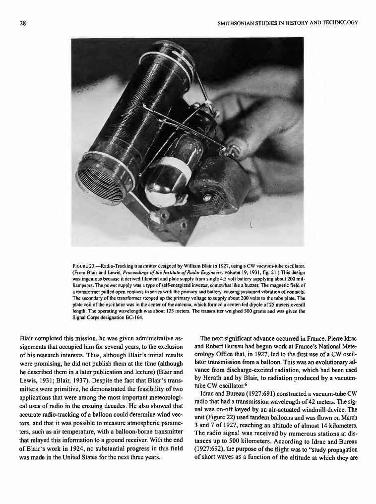
28 SMITHSONIAN STUDIES IN HISTORY AND TECHNOLOGY
FIGURE 23.—Radio-Tracking transmitter designed by William Blair in 1927, using a CW vacuum-tube oscillator. (From Blair and Lewis, Proceedings of the Institute of Radio Engineers, volume 19, 1931, fig. 21.) This design was ingenious because it derived filament and plate supply from single 4.5 volt battery supplying about 200 mil-liamperes. The power supply was a type of self-energized inverter, somewhat like a buzzer. The magnetic field of a transformer pulled open contacts in series with the primary and battery, causing sustained vibration of contacts. The secondary of the transformer stepped up the primary voltage to supply about 200 volts to the tube plate. The plate coil of the oscillator was in the center of the antenna, which formed a center-fed dipole of 25 meters overall length. The operating wavelength was about 125 meters. The transmitter weighed 500 grams and was given the Signal Corps designation BC-164.
Blair completed this mission, he was given administrative assignments that occupied him for several years, to the exclusion of his research interests. Thus, although Blair's initial results were promising, he did not publish them at the time (although he described them in a later publication and lecture) (Blair and Lewis, 1931; Blair, 1937). Despite the fact that Blair's transmitters were primitive, he demonstrated the feasibility of two applications that were among the most important meteorological uses of radio in the ensuing decades. He also showed that accurate radio-tracking of a balloon could determine wind vectors, and that it was possible to measure atmospheric parameters, such as air temperature, with a balloon-borne transmitter that relayed this information to a ground receiver. With the end of Blair's work in 1924, no substantial progress in this field was made in the United States for the next three years.
The next significant advance occurred in France. Pierre Idrac and Robert Bureau had begun work at France's National Meteorology Office that, in 1927, led to the first use of a CW oscillator transmission from a balloon. This was an evolutionary advance from discharge-excited radiation, which had been used by Herath and by Blair, to radiation produced by a vacuum-tube CW oscillator.6
Idrac and Bureau (1927:691) constructed a vacuum-tube CW radio that had a transmission wavelength of 42 meters. The signal was on-off keyed by an air-actuated windmill device. The unit (Figure 22) used tandem balloons and was flown on March 3 and 7 of 1927, reaching an altitude of almost 14 kilometers. The radio signal was received by numerous stations at distances up to 500 kilometers. According to Idrac and Bureau (1927:692), the purpose of the flight was to "study propagation of short waves as a function of the altitude at which they are
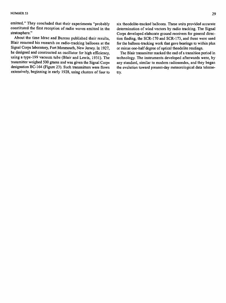
NUMBER 53 29
emitted." They concluded that their experiments "probably constituted the first reception of radio waves emitted in the stratosphere."
About the time Idrac and Bureau published their results, Blair resumed his research on radio-tracking balloons at the Signal Corps laboratory, Fort Monmouth, New Jersey. In 1927, he designed and constructed an oscillator for high efficiency, using a type-199 vacuum tube (Blair and Lewis, 1931). The transmitter weighed 500 grams and was given the Signal Corps designation BC-164 (Figure 23). Such transmitters were flown extensively, beginning in early 1928, using clusters of four to
six theodolite-tracked balloons. These units provided accurate determination of wind vectors by radio tracking. The Signal Corps developed elaborate ground receivers for general direction finding, the SCR-170 and SCR-173, and these were used for the balloon-tracking work that gave bearings to within plus or minus one-half degree of optical theodolite readings.
The Blair transmitter marked the end of a transition period in technology. The instruments developed afterwards were, by any standard, similar to modern radiosondes, and they began the evolution toward present-day meteorological data telemetry.

5. The Prototypes, 1929-1930
The previous sections have outlined the development of balloon-borne instrumentation and advances in telegraphy and radio that provided the technological basis for the radiosonde. Indeed, the radiosonde was described earlier in this publication as a "natural" extension of the balloonsonde. In order to understand this process more clearly, it is useful to place the advent of the radiosonde in the wider context of the evolution of meteorology.
The development of meteorology as a science in the nineteenth century occurred chiefly in synoptic meteorology, that is, in the creation of networks of widely scattered stations that could report simultaneous observations to a central bureau on a frequent basis. The ability to gather synoptic data played an important role in the growth of meteorological theory. The first international compilations of synoptic weather charts were made in the early 1800s, and in the ensuing years methods for obtaining the data for these charts steadily improved with the introduction of better measuring instruments and the creation of telegraphic networks. Toward the end of the nineteenth century, improvements in the design of kites and balloons made it possible to obtain upper-altitude data on a more frequent basis.
In the first decades of the twentieth century, improvements in weather science were attributable partly to advances in theory and partly to the increasingly intensive exploration of the upper atmosphere. Theoretical advances were made in the early 1920s by scientists, primarily Vilhelm Bjerknes, who led Scan-danavian researchers in establishing a new conceptual foundation for atmospheric science (Friedman, 1982:343). Bjerknes' work was supported by experimental data acquired after 1900 by sounding the upper atmosphere. Balloons were developed that allowed balloonsondes to reach altitudes of 20 to 30 kilometers. Aeronautical progress in other areas made it possible to routinely use captive balloons and airplanes to make observations at lower altitudes. As the ability to obtain such data on a wide scale was enhanced, it became increasingly apparent that synoptic charts of temperature, pressure, humidity, and wind vectors at various levels of the atmosphere were essential to both weather forecasting and to advances in the meteorological theory upon which forecasts were based.
During the period in which this evolution of meteorological theory and practice occurred, the demand for accurate weather information grew. The military requirement for such information (as described in the previous section) had expanded dramatically during World War I and remained at a high level in the postwar years. The need for weather information also expanded in the civilian sectors of industrialized countries, prompted by factors such as the more extensive agricultural ex
ploitation of marginal land and the increased use of airplanes to transport people and cargo. Therefore, meteorologists realized that the need for more and better weather information could be satisfied only by an expansion of programs to probe the upper atmosphere on a synoptic basis. By the 1920s, it was apparent that the serious deficiencies of existing means for obtaining data at various altitudes would inhibit the implementation of such programs.
Methods for probing the atmosphere, using kites, captive balloons, and airplanes, were capable of providing the timely data required in the preparation of synoptic weather charts. A major deficiency of these traditional means, however, was that none was usable at all times or in all locations. Captive balloons could not be deployed in high winds. Kites, on the other hand, were useless when the wind speed was very low. The tether necessary for both vehicles was a significant danger to airplanes (as attested to by several fatal accidents in World War I). Also, kites and captive balloons occasionally broke loose, and their dangling steel cables created a hazard, especially when they came in contact with electrical power cables. These potential dangers relegated the use of tethered vehicles to remote, relatively unpopulated locales. Airplanes were used to obtain weather data toward the end of World War I, and in the early 1920s self-registering meteorographs were developed specifically for use in airplanes, which flew only in good weather and generally only during daylight hours.
The balloonsonde met the need for an atmospheric probe that was usable day or night in virtually all weather conditions. Moreover, they could be launched from almost any location. These important advantages were offset, however, by a significant disadvantage: a delay, usually of several days, before the balloonsonde was found and returned to the central bureau. This seriously compromised the usefulness of balloonsonde data in preparing daily forecasts. Nevertheless, despite this problem, low-cost balloonsondes were developed and used extensively during the 1920s to investigate the atmosphere (Middleton and Spilhaus, 1953:231) (see Section 1, "Nontelemeter-ing Balloonsondes: 1892-1929," Figures 11, 12).
Meteorologists soon realized that the balloonsonde possessed all the characteristics to make it ideal for obtaining synoptic data, if the time-delay problem could be solved inexpensively.
Using a radio to transmit balloonsonde data to a ground receiver was an obvious solution that had been discussed as early as 1914 by German meteorologists Herath and Robitzsch. Indeed, Beelitz (1954:67) quoted a statement by Herath that indicated that Herath's work with Robitzsch in 1917 on the use of
30
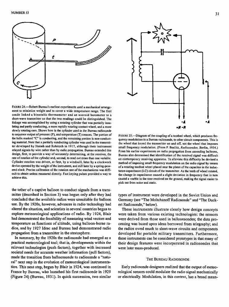
NUMBER 53 31
FIGURE 24.—Robert Bureau's earliest experiments used a mechanical arrangement to minimize weight and to cover a wide temperature range. The first sonde linked a bimetalic thermometer and an aneroid barometer to a short-wave transmitter so that the two readings could be distinguished. The linkage was accomplished by using a rotating cylinder that was partially insulating and partly conducting, a more rapidly rotating contact wheel, and a more slowly rotating cam. Shown here is the cylinder used in the Bureau radiosonde to sequence output of pressure (P), and temperature (T) sensors. The portion of the helix marked "C" is conducting, and the remaining portion is non-conducting material. Note that a partially conducting cylinder was used in the transmitter developed by Herath and Robitzch in 1917, although their instrument relayed signals by wire rather than by radio propagation. Bureau extended this design, first, to provide a way of accurately determining, at the receiver, the rate of rotation of the cylinder and, second, to read out more than one variable. Cylinder rotation was driven, at first, by a windmill, later by a clockwork device operated by the weight of the instrument, and still later by a spring-powered clock. Precise calibration of the rotation rate of the mechanisms was difficult to obtain unless measured directly. Fast keying pulses provided a way to achieve this.
the tether of a captive balloon to conduct signals from a transmitter (described in Section 3) was begun only after they had concluded that the available radios were unsuitable for balloon use. By the 1920s, however, advances in radio technology had altered the situation, and scientists in several countries began to explore meteorological applications of radio. By 1924, Blair had demonstrated the feasibility of measuring wind vectors and temperature as functions of altitude, using balloon-borne radios, and by 1927 Idrac and Bureau had demonstrated radio propagation from a transmitter in the stratosphere.
In summary, by the 1920s the radiosonde had emerged as a practical meteorological tool; that is, developments within the relevant technologies (push factors), together with increased societal needs for accurate weather information (pull factors), made the transition from balloonsonde to radiosonde a "natural" next step in the evolution of meteorological instrumentation. This next step, begun by Blair in 1924, was continued in France by Bureau, who launched his first radiosonde in 1929 (Figure 24) (Bureau, 1931). In quick succession, two similar
•A *M-tt
FIGURE 25.—Diagram of the coupling of a toothed wheel, which produces frequency modulation in a Bureau radiosonde, to other circuit components. This is the wheel that keyed the transmitter on and off, not the wheel that imposes small frequency modulation. (From P. Beelitz, Radiosonden, Berlin, 1954.) From his earlier experiments on radio propagation from ascending balloons, Bureau also determined that identification of the received signal was difficult on contemporary receiving apparatus. To alleviate this difficulty he devised a method of imposing small frequency modulation on the radio signal by means of a rotating toothed wheel placed near the plates of the capacitor in the inductance-capacitance (LC) circuit of the transmitter. As the teeth of wheel rotated, the change in capacitance caused a slight deviation in frequency that in turn caused a warble in the tone received on the ground, making the signal easier to pick out from noise and static.
types of instrument were developed in the Soviet Union and Germany (see "The Moltchanoff Radiosonde" and "The Duck-ert Radiosonde," below).
These instruments illustrate clearly how design concepts were taken from various existing technologies: the sensors were derived from those used in balloonsondes; the data processing was based upon ideas borrowed from telegraphy; and the radios owed much to short-wave circuits and components developed for portable military transmitters. Furthermore, these instruments can be considered prototypes in that many of their design features were incorporated in radiosondes that were later mass-produced.
THE BUREAU RADIOSONDE
Early radiosonde designers realized that the output of meteorological sensors could modulate the radio signal mechanically or electrically. Modulation, in this context, has a broad mean-

32 SMITHSONIAN STUDIES IN HISTORY AND TECHNOLOGY
FIGURE 26.—The first "thermoradio" flown by Robert Bureau. From left to right, the windmill and toothed wheel for modulation, the half-metal, half-insulator cylinder, the toothed wheel carrying the on-off keying cam (i.e., the metal spindle parallel to the cylinder), the arm of the thermometer, and the bimetallic thermometer itself. (From R. Bureau, La Meteorologie, volume 7, 1931.)
ing of changing the radio-frequency carrier signal in some distinctive manner that conveys information. The simplest method of modulation is to turn the signal on and off in some timed sequence. A more complex modulation method is to change the frequency, phase, or amplitude of the carrier signal.
In mechanical modulation, displacement of an arm, which was the output of standard sensors, such as the bimetallic thermometer or the aneroid barometer, was linked to the transmitter by an electromechanical transducer that altered the radio signal. It is easiest for mechanical modulation to switch the signal on and off, but other types of modulation were possible and, in fact, Bureau used one such scheme to alter the radiosonde signal frequency with a rotating toothed wheel placed close to the transmitter tuning circuit.
For electrical modulation, special sensors, such as a temperature-sensitive capacitor, were used as components of the transmitter circuit. Changes in the electrical characteristics of such components with variation of the atmospheric parameter being measured, in turn, altered the radio signal, usually through a change in frequency. The earliest application of electrical modulation was the radiosonde flown by Blair in 1924, where the
frequency of the radio signal was changed by transmitter components that responded to variations in temperature (Blair, 1937:2).
Robert Bureau was aware of these design permutations and, starting in 1927, he experimented with many of them at his laboratory (Idrac and Bureau, 1927). Bureau flew his first radiosonde, equipped only with a thermometer, on 7 January 1929 (Figure 26). In the spring of 1929, he flew an instrument (Figure 27) that sequenced the output of a thermometer and a barometer with a 10-toothed wheel (with one tooth missing) geared directly to the cylinder on which the thermometer and barometer arms operated (Bureau, 1931). The missing tenth tooth in the wheel produced a gap in the small frequency modulations signaling a full turn of the cylinder. Therefore, by counting the number of "pips" on the recording produced by the receiver on the ground, the rotational speed was determined. The speed was then used to calibrate the on-off "dot" rate produced by the rotating cam and cylinder mechanism just as with the earlier system but eliminating one of the wheel mechanisms. The receiver provided an output current that drove the arm of a register that scratched a visual record on smoked-glass (Figure

NUMBER 53 33
FIGURE 27.—The "barothermoradio" of Robert Bureau, which was flown in the spring of 1929. The windmill is at the top. From left to right are the bimetallic thermometer, the cylinder, and beneath it the cams with their train of gears, and a lever, which, under the action of the cams, is supported periodically on the stylus of the barometer, whose capsule is at right. The arm of the thermometer is on the bottom of the cylinder, and the arm of the barometer is at the top. (From R. Bureau, La Meteorologie, volume 7, 1931.)
28). Although Bureau had experimented between 1927 and 1929 with wavelengths as short as four meters (Figure 29), he rejected these higher frequencies because of reception difficulty when the line of propagation was near the horizon. Bureau's first design was modified over the next decade, but the basic principle (the Olland cycle) remained the same, and the longer wavelength, 60 meters, was retained.
It is pertinent to note that Bureau (1931:306) coined the term "radiosonde," using it to designate balloon-borne payloads that transmit atmospheric parameters (usually pressure, temperature, and humidity) to a ground receiver via radio. This is still the most common usage of the term, although some writers apply it to the balloon and payload as a system. Also, in current usage radiosonde can refer to special balloon-borne payloads that transmit measurements of nonatmospheric parameters, such as cosmic-ray intensity. Those writers who use this narrower defi
nition generally use the term "meteorological radiosonde" to refer to the low-cost units that measure only pressure, temperature, and humidity. In 1938 the U.S. Weather Bureau officially adopted the term "radiosonde" to refer to "meteorological radiosondes," in preference to an earlier term "radio-meteorograph" (Snyder and Bragaw, 1986:122, footnote 8).
THE MOLTCHANOFF RADIOSONDE
At a symposium in October 1931, Soviet scientist Pazel Moltchanoff, a scientist at the Institute of Aerology at Sloutzk, U.S.S.R., reported the successful flight of a balloon-borne transmitter that relayed temperature and pressure data to a ground receiver. According to Beelitz (1954:69), Moltchanoff also stated that this flight "was the first one in the world where a radiosonde was used for exploration of the atmosphere." This
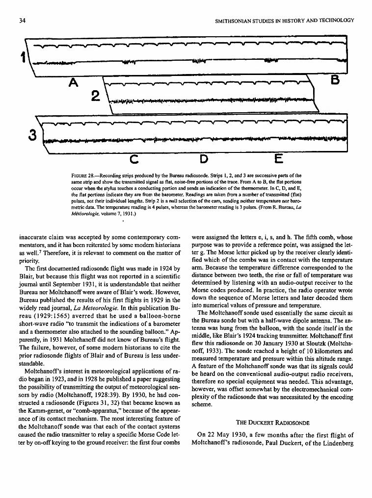
34 SMITHSONIAN STUDIES IN HISTORY AND TECHNOLOGY
- v — v — ^ s/ v \f s/ • — s / -v v v sr—v \j \f—>J w s/ w w *
V ' " " V -V——V" \/ - v •»>/ " V ^ V ' V ' ' V V""*^/" B ,^j^^^#itr+W*r*+4M**'**"Vi ""»"' E»*l|»n^*^HwHPM'*
V •^ « ' • v " " ' v/" V •s/ "V ' V *N/"'"V V ' 'V" V ' V V V
HUE ft i m m u m j U i iyr V * * * ^ ^ * * * * * * ^ * V * "W» «•»•***»«***>»- PM> » * «»*ft»i»m'
FIGURE 28.—Recording strips produced by the Bureau radiosonde. Strips 1, 2, and 3 are successive parts of the same strip and show the transmitted signal as flat, noise-free portions of the trace. From A to B, the flat portions occur when the stylus touches a conducting portion and sends an indication of the thermometer. In C, D, and E, the flat portions indicate they are from the barometer. Readings are taken from a number of transmitted (flat) pulses, not their individual lengths. Strip 2 is a null selection of the cam, sending neither temperature nor barometric data. The temperature reading is 4 pulses, whereas the barometer reading is 3 pulses. (From R. Bureau, La Meteorologie, volume 7, 1931.)
inaccurate claim was accepted by some contemporary commentators, and it has been reiterated by some modern historians as well.7 Therefore, it is relevant to comment on the matter of priority.
The first documented radiosonde flight was made in 1924 by Blair, but because this flight was not reported in a scientific journal until September 1931, it is understandable that neither Bureau nor Moltchanoff were aware of Blair's work. However, Bureau published the results of his first flights in 1929 in the widely read journal, La Meteorologie. In this publication Bureau (1929:1565) averred that he used a balloon-borne short-wave radio "to transmit the indications of a barometer and a thermometer also attached to the sounding balloon." Apparently, in 1931 Moltchanoff did not know of Bureau's flight. The failure, however, of some modern historians to cite the prior radiosonde flights of Blair and of Bureau is less understandable.
Moltchanoff's interest in meteorological applications of radio began in 1923, and in 1928 he published a paper suggesting the possibility of transmitting the output of meteorological sensors by radio (Moltchanoff, 1928:39). By 1930, he had constructed a radiosonde (Figures 31, 32) that became known as the Kamm-geraet, or "comb-apparatus," because of the appearance of its contact mechanism. The most interesting feature of the Moltchanoff sonde was that each of the contact systems caused the radio transmitter to relay a specific Morse Code letter by on-off keying to the ground receiver: the first four combs
were assigned the letters e, i, s, and h. The fifth comb, whose purpose was to provide a reference point, was assigned the letter g. The Morse letter picked up by the receiver clearly identified which of the combs was in contact with the temperature arm. Because the temperature difference corresponded to the distance between two teeth, the rise or fall of temperature was determined by listening with an audio-output receiver to the Morse codes produced. In practice, the radio operator wrote down the sequence of Morse letters and later decoded them into numerical values of pressure and temperature.
The Moltchanoff sonde used essentially the same circuit as the Bureau sonde but with a half-wave dipole antenna. The antenna was hung from the balloon, with the sonde itself in the middle, like Blair's 1924 tracking transmitter. Moltchanoff first flew this radiosonde on 30 January 1930 at Sloutzk (Moltchanoff, 1933). The sonde reached a height of 10 kilometers and measured temperature and pressure within this altitude range. A feature of the Moltchanoff sonde was that its signals could be heard on the conventional audio-output radio receivers, therefore no special equipment was needed. This advantage, however, was offset somewhat by the electromechanical complexity of the radiosonde that was necessitated by the encoding scheme.
THE DUCKERT RADIOSONDE
On 22 May 1930, a few months after the first flight of Moltchanoff's radiosonde, Paul Duckert, of the Lindenberg

NUMBER 53 35
FIGURE 29.—Later model of the Bureau radiosonde incorporating a clockwork-driven cylinder. (From P. Beelitz, Radiosonden, Berlin, 1954, fig. 25.) The transmitter on Bureau's sensor-less flight in 1927 had used a wavelength of 42 meters and a quarter-wave antenna. Transmitters on the 1929 flights used a wavelength of approximately 60 meters (4.8 MHz) and retained the quarter-wave antenna design, which allowed the radiosonde to be at the balloon, with the antenna extending down away from it. In later models, the cylinder was rotated by a constant-speed, spring-operated clockwork, and provision was made for the inclusion of a hair hygrometer to make the instrument capable of measuring humidity as well as temperature and pressure. Bureau's work to simplify transmitter circuitry and to find a suitable wavelength-established design—a single triode Hartley oscillator directly coupled to a quarter- or half-wave antenna with dry plate and filament batteries—was followed by almost all investigators during the next decade.
Observatory in Germany, flew a radiosonde of his own design. The sonde, which attained a height of 15 kilometers, transmitted measurements of pressure and temperature to a ground-based receiver (Duckert, 1932).
Duckert's radiosonde differed from those of Bureau and of Moltchanoff in that it used a thermometer to vary the capaci
tance of the transmitter inductor-capacitor (LC) tuning circuit. This capacitance change varied the frequency of the radio signal. The pressure was measured by means of a Bourdon tube and was indicated by interruptions of the signal. Blair had pioneered the method used by Duckert to measure temperature by varying the frequency of the signal with a temperature-sensitive
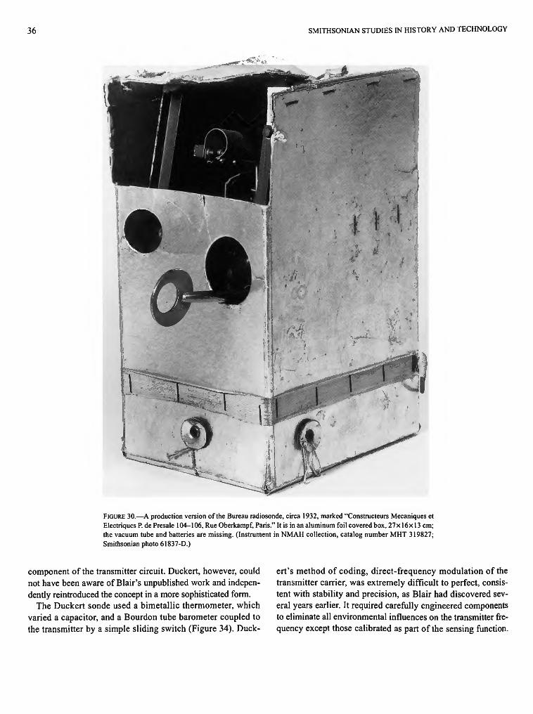
36 SMITHSONIAN STUDIES IN HISTORY AND TECHNOLOGY
FIGURE 30.—A production version of the Bureau radiosonde, circa 1932, marked "Constructeurs Mecaniques et Electriques P. de Presale 104-106, Rue Oberkampf, Paris." It is in an aluminum foil covered box, 27x16x13 cm; the vacuum tube and batteries are missing. (Instrument in NMAH collection, catalog number MHT 319827; Smithsonian photo 61837-D.)
component of the transmitter circuit. Duckert, however, could not have been aware of Blair's unpublished work and independently reintroduced the concept in a more sophisticated form.
The Duckert sonde used a bimetallic thermometer, which varied a capacitor, and a Bourdon tube barometer coupled to the transmitter by a simple sliding switch (Figure 34). Duck
ert's method of coding, direct-frequency modulation of the transmitter carrier, was extremely difficult to perfect, consistent with stability and precision, as Blair had discovered several years earlier. It required carefully engineered components to eliminate all environmental influences on the transmitter frequency except those calibrated as part of the sensing function.
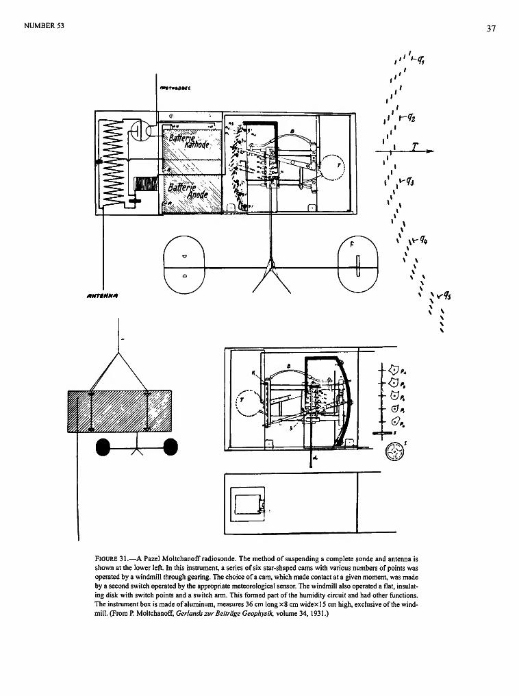
NUMBER 53 37
FIGURE 31.—A Pazel Moltchanoff radiosonde. The method of suspending a complete sonde and antenna is shown at the lower left. In this instrument, a series of six star-shaped cams with various numbers of points was operated by a windmill through gearing. The choice of a cam, which made contact at a given moment, was made by a second switch operated by the appropriate meteorological sensor. The windmill also operated a flat, insulating disk with switch points and a switch arm. This formed part of the humidity circuit and had other functions. The instrument box is made of aluminum, measures 36 cm long x8 cm widex 15 cm high, exclusive of the windmill. (From P. Moltchanoff, Gerlands zur Beitrage Geophysik, volume 34, 1931.)

38 SMITHSONIAN STUDIES IN HISTORY AND TECHNOLOGY
FIGURE 32.—Mechanical parts of Moltchanoff's first radiosonde design showing the rotating contact and sensors. (Instrument in NMAH collection, catalog number MHT 316262; Smithsonian photo 48467-A.)
In a later model (Figure 35), all circuit components (except for the capacitor linked to the thermometer) were vacuum sealed in a glass tube; a feature that significantly improved performance in the hostile operational environment of radiosondes. By the mid-1930s, the cumbersome thermometer-capacitor assemblage was replaced by a simple capacitor with a temperature-sensitive dielectric. Provision for measuring and transmitting humidity was included (Duckert, 1932, 1933, 1935).
The instruments described above constitute three distinct types, according to the means for converting the indications of
the sensors into modulation of the radio transmissions. The three methods are chronometric (Bureau), coding (Moltchanoff), and frequency modulation (Duckert). From 1931 to 1940, more than one dozen radiosonde designs were manufactured (see Beelitz, 1954), but all were based upon one of these three methods. These three designs can be considered prototypical of the instruments that followed.
These categories are not fundamental in a radio engineering sense because they do not represent mutually exclusive ways in which to code and modulate information onto a radio transmis-

NUMBER 53 39
FIGURE 33.—Paul Duckert's first radiosonde. A continuous radio signal was emitted whose frequency varied with temperature, whereas pressure was indicated by interrupting the signal by a Bourdon tube (c) and a toothed wheel (d). One plate of the capacitor (b) was moved by a bimetallic thermometer (a and h). The complete radio transmitter was inside the glass tube (f). (From Duckert, Beitrdge zur Physik der Freien Atmosphare, volume 18, 1932.)
sion. Nevertheless, they represent the basic categories into which radiosonde evolution can be divided during the period from 1931 to 1940. The basic radio-frequency design of numerous radiosondes, both during the prototype phase and dur
ing later development, underwent remarkably little change. The transmitters, with rare exceptions, used a single triode connected as a radio-frequency oscillator with the inductance-capacitance tank circuit coupled to a resonant antenna.
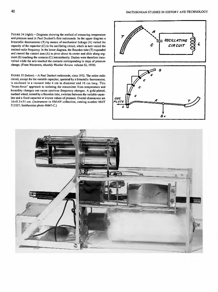
40
FIGURE 34 (right).—Diagrams showing the method of measuring temperature and pressure used in Paul Duckert's first radiosonde. In the upper diagram a bimetallic thermometer (T) by means of mechanical linkage (A) varied the capacity of the capacitor (C) in the oscillating circuit, which in turn varied the emitted radio frequency. In the lower diagram, the Bourdon tube (T) expanded and caused the contact arm (A) to pivot about its center and slide along segment (S) touching the contacts (C) intermittently. Dashes were therefore transmitted while the arm touched the contacts corresponding to steps of pressure change. (From Wenstrom, Monthly Weather Review, volume 62, 1934).
FIGURE 35 (below).—A Paul Duckert radiosonde, circa 1932. The entire radio circuit, except for the variable capacitor, operated by a bimetallic thermometer, is enclosed in a vacuum tube 6 cm in diameter and 16 cm long. This "brute-force" approach to isolating the transmitter from temperature and humidity changes can cause spurious frequency changes. A gold-plated, toothed wheel, turned by a Bourdon tube, switches between the variable capacitor and a fixed capacitor at known values of pressure. Overall dimensions are 16x8.5x31 cm. (Instrument in NMAH collection, catalog number MHT 313527; Smithsonian photo 48467-C.)
SMITHSONIAN STUDIES IN HISTORY AND TECHNOLOGY
|
V A
OSCILLATING § CIRCUIT <
osc PLATE
// C
// C
II C
C U
^ P s c
____£
B +
T / /
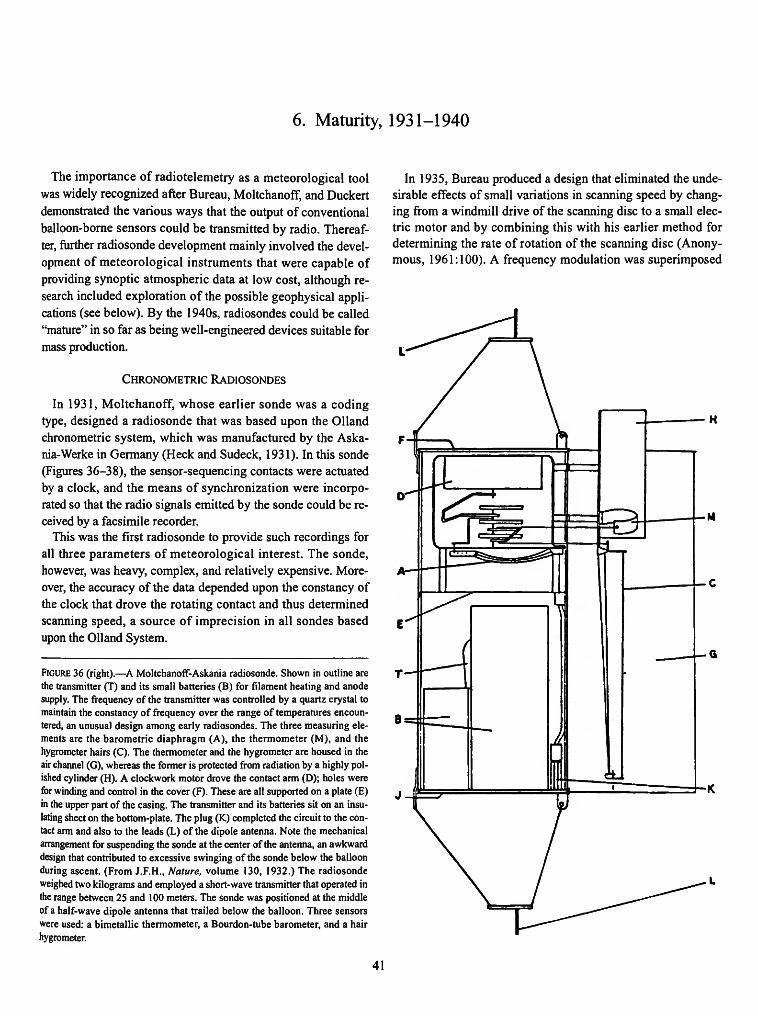
6. Maturity, 1931-1940
The importance of radiotelemetry as a meteorological tool was widely recognized after Bureau, Moltchanoff, and Duckert demonstrated the various ways that the output of conventional balloon-borne sensors could be transmitted by radio. Thereafter, further radiosonde development mainly involved the development of meteorological instruments that were capable of providing synoptic atmospheric data at low cost, although research included exploration of the possible geophysical applications (see below). By the 1940s, radiosondes could be called "mature" in so far as being well-engineered devices suitable for mass production.
CHRONOMETRIC RADIOSONDES
In 1931, Moltchanoff, whose earlier sonde was a coding type, designed a radiosonde that was based upon the Olland chronometric system, which was manufactured by the Aska-nia-Werke in Germany (Heck and Sudeck, 1931). In this sonde (Figures 36-38), the sensor-sequencing contacts were actuated by a clock, and the means of synchronization were incorporated so that the radio signals emitted by the sonde could be received by a facsimile recorder.
This was the first radiosonde to provide such recordings for all three parameters of meteorological interest. The sonde, however, was heavy, complex, and relatively expensive. Moreover, the accuracy of the data depended upon the constancy of the clock that drove the rotating contact and thus determined scanning speed, a source of imprecision in all sondes based upon the Olland System.
FIGURE 36 (right).—A Moltchanoff-Askania radiosonde. Shown in outline are the transmitter (T) and its small batteries (B) for filament heating and anode supply. The frequency of the transmitter was controlled by a quartz crystal to maintain the constancy of frequency over the range of temperatures encountered, an unusual design among early radiosondes. The three measuring elements are the barometric diaphragm (A), the thermometer (M), and the hygrometer hairs (C). The thermometer and the hygrometer are housed in the air channel (G), whereas the former is protected from radiation by a highly polished cylinder (H). A clockwork motor drove the contact arm (D); holes were for winding and control in the cover (F). These are all supported on a plate (E) in the upper part of the casing. The transmitter and its batteries sit on an insulating sheet on the bottom-plate. The plug (K) completed the circuit to the contact arm and also to the leads (L) of the dipole antenna. Note the mechanical arrangement for suspending the sonde at the center of the antenna, an awkward design that contributed to excessive swinging of the sonde below the balloon during ascent. (From J.F.H., Nature, volume 130, 1932.) The radiosonde weighed two kilograms and employed a short-wave transmitter that operated in the range between 25 and 100 meters. The sonde was positioned at the middle of a half-wave dipole antenna that trailed below the balloon. Three sensors were used: a bimetallic thermometer, a Bourdon-tube barometer, and a hair hygrometer.
In 1935, Bureau produced a design that eliminated the undesirable effects of small variations in scanning speed by changing from a windmill drive of the scanning disc to a small electric motor and by combining this with his earlier method for determining the rate of rotation of the scanning disc (Anonymous, 1961:100). A frequency modulation was superimposed
41
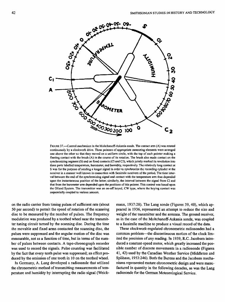
42 SMITHSONIAN STUDIES IN HISTORY AND TECHNOLOGY
QfrO^QfrOg-
*Q*>0200 100 °
FIGURE 37.—Control mechanism in the Moltchanoff-Askania sonde. The contact arm (A) was rotated continuously by a clockwork drive. Three pointers of appropriate measuring elements were arranged one above the other so that they moved on a uniform circle, with the top of each pointer making a fleeting contact with the brush (A) in the course of its rotation. The brush also made contact on the synchronizing segment (S) and on fixed contacts (CI and C2), which jointly marked its revolution into three parts labelled temperature, barometer, and humidity, respectively. The relatively long contact at S was for the purpose of sending a longer signal in order to synchronize the recording cylinder at the receiver in a manner well known in connection with facsimile receivers of the period. The time interval between the end of the synchronizing signal and contact with the temperature arm thus depended upon the instantaneous position of the latter; similarly, the interval between the signal from CI and that from the barometer arm depended upon the positions of this pointer. This control was based upon the Olland System. The transmitter was an on-off keyed, CW type, where the keying contact was sequentially coupled to various sensors.
on the radio carrier from timing pulses of sufficient rate (about 50 per second) to permit the speed of rotation of the scanning disc to be measured by the number of pulses. The frequency modulation was produced by a toothed wheel near the transmitter tuning circuit turned by the scanning disc. During the time the movable and fixed arms contacted the scanning disc, the pulses were suppressed and the angular motion of the disc was measurable, not as a function of time, but in terms of the number of pulses between contacts. A tape-chronograph recorder was used to record the signals. Pulse counting was facilitated by the fact that every tenth pulse was suppressed; an effect produced by the omission of one tooth in 10 on the toothed wheel.
In Germany, A. Lang developed a radiosonde that utilized the chronometric method of transmitting measurements of temperature and humidity by interrupting the radio signal (Weick-
mann, 1937:28). The Lang sonde (Figures 39, 40), which appeared in 1936, represented an attempt to reduce the size and weight of the transmitter and the antenna. The ground receiver, as in the case of the Moltchanoff-Askania sonde, was coupled to a facsimile machine to produce a visual record of the data.
These clockwork-regulated chronometric radiosondes had a common problem—the discontinuous motion of the clock limited the precision of any reading. In 1939, R.C. Jacobsen introduced a constant-speed motor, which greatly increased the possible number of discrete movements in a radiosonde (Figures 41, 42) used by the Canadian Weather Service (Middleton and Spilhaus, 1953:246). Both the Bureau and the Jacobsen mechanisms represented mature chronometric design and were manufactured in quantity in the following decades, as was the Lang radiosonde for the German Meteorological Service.
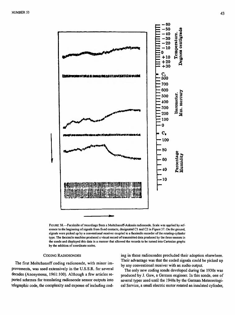
NUMBER 53 43
l li^i^rt*1»" |%
mummitmMmimauimMmwitimwvitvm
lf%«/*'t*%***'' •
*** ,««*«»"+»*
tm0mBmmnmmmmtmiimtmmmitmmtimmmm*tk
ft******* m*
^l|||WBM«
\
^-nmm
-60 -50 -40 -30 -20 -10 0 + 10 + 20 + 30
Ct
soo ;700 600 500 •400 •300 •200 ;100 •0 C,
•100
•80
•60
-40
-10
eg 2 g 8,8
a p
&
If « '3
FIGURE 38.—Facsimile of recordings from a Moltchanoff-Askania radiosonde. Scale was applied by reference to the beginning of signals from fixed contacts, designated CI and C2 in Figure 37. On the ground, signals were picked up by a conventional receiver coupled to a facsimile recorder of the rotating-cylinder type. The facsimile machine produced a visual record of transmitted data produced by the three sensors in the sonde and displayed this data in a manner that allowed the records to be turned into Cartesian graphs by the addition of coordinate scales.
CODING RADIOSONDES
The first Moltchanoff coding radiosonde, with minor improvements, was used extensively in the U.S.S.R. for several decades (Anonymous, 1961:100). Although a few articles reported schemes for translating radiosonde sensor outputs into telegraphic code, the complexity and expense of including cod
ing in these radiosondes precluded their adoption elsewhere. Their advantage was that the coded signals could be picked up by any conventional receiver with an audio output.
The only new coding sonde developed during the 1930s was produced by J. Gaw, a German engineer. In this sonde, one of several types used until the 1940s by the German Meteorological Service, a small electric motor rotated an insulated cylinder,

44 SMITHSONIAN STUDIES IN HISTORY AND TECHNOLOGY
FIGURE 39.—Diagram of the mechanical parts of an A. Lang radiosonde and fragmentary transmitter circuit. The reference contact (Z) is adjacent to the hygrometer arm. An aneroid capsule and pressure arm switch are shown at the top. A starred-wheel temperature contact and rotating cylinder (W) are at the bottom of the figure. (From L. Weickmann, Denkschrift Uber Radio-sonde-Konstructionen, Berlin, 1938.) The sensors were a bimetallic thermometer, an aneroid barometer, and a hair hygrometer. The novel feature was that, instead of a single contact arm, the bimetallic thermometer rotated a star-shaped contact; an arrangement that, in effect, expanded the temperature
scale. The hair hygrometer moved an arm that, in conjunction with a fixed contact, shut down the transmitter once each revolution for a time period indicative of the humidity. The clock drove two coaxial cylinders, one with a conducting band parallel to the axis, the other a conducting helix. Both temperature and humidity were based upon a time-cycle principle, but the aneroid barometer simply operated a switch that interrupted the radio signal at predetermined pressure values, thus allowing the sequence of interruptions to be interpreted in terms of pressure. (Smithsonian photo 63882.)

NUMBER 53 45
FIGURE 40.—An A. Lang radiosonde, with a short-wave transmitter (10.81 meters; 27.75 MHz), which weighed, with the mechanical arrangements described in the text, 560 grams. The wavelength used was considered very short in the 1930s. The mechanical arrangements are in the upright casing; the radio transmitter is in the cylinder. (Instrument in NMAH collection, catalog number MHT 322211; Smithsonian photo 61836.)
portions of which had a conducting surface. Contact arms from a bimetallic thermometer, aneroid barometer, and hair hygrometer touched conducting portions of the rotating cylinder in a way that produced combinations of two Morse letters for each sensor. The complete cycle for the three sensors was repeated eight times per minute. Signals could be heard on the ground by using an ordinary radio receiver and could be written down as Morse letters that were interpreted later as values of pressure, temperature, and humidity.
FREQUENCY MODULATION RADIOSONDES
The Duckert radiosonde underwent various modifications during the 1930s (Duckert, 1932, 1933, 1935:573-584), including replacement of the oil-filled variable condenser used as a temperature sensor by an "electric" thermometer consisting of a temperature-sensitive capacitor. This was made possible by the development of a material whose dielectric constant had a large temperature-coefficient. Such material then was used as
the nonconducting portion of a capacitor whose capacitance became a predictable function of temperature. Other Duckert sondes, unlike the first model that only measured temperature and pressure, incorporated a hygrometer and a means for transmitting humidity by varying the length of time the radio frequency was turned on. In later models, the pressure switch, which in earlier designs simply interrupted the signal, switched from the variable capacitor to a fixed-reference capacitor in order to provide a means of monitoring transmitter stability. These later designs also included ceramic insulation to make the transmitter more stable. The re-engineered designs of the Duckert sonde were mass produced throughout the 1930s by the German firm of Telefunken.
Radio-frequency modulation, which Blair had used in his radiosonde of 1924, and which Bureau mentioned in an article published early in 1931, was used in Duckert radiosondes as early as 1930. That same year Vilho Vaisala, a Finnish engineer, independently conceived of frequency modulation as a simpler alternative to the Moltchanoff coding sonde (Vaisala, 1932).
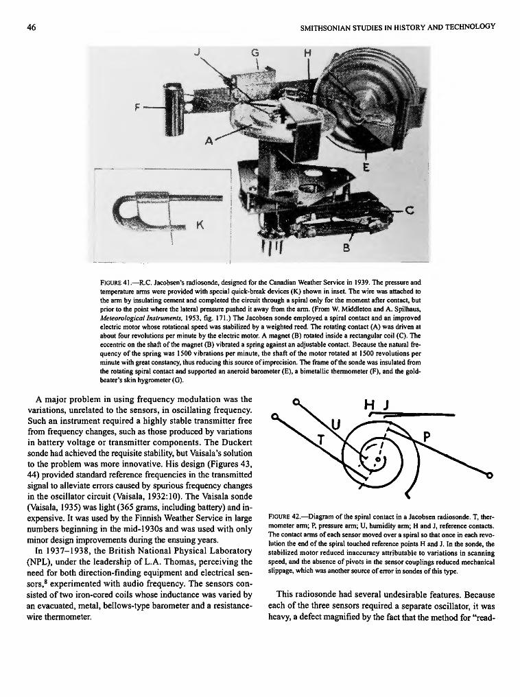
46 SMITHSONIAN STUDIES IN HISTORY AND TECHNOLOGY
FIGURE 41.—R.C. Jacobsen's radiosonde, designed for the Canadian Weather Service in 1939. The pressure and temperature arms were provided with special quick-break devices (K.) shown in inset. The wire was attached to the arm by insulating cement and completed the circuit through a spiral only for the moment after contact, but prior to the point where the lateral pressure pushed it away from the arm. (From W. Middleton and A. Spilhaus, Meteorological Instruments, 1953, fig. 171.) The Jacobsen sonde employed a spiral contact and an improved electric motor whose rotational speed was stabilized by a weighted reed. The rotating contact (A) was driven at about four revolutions per minute by the electric motor. A magnet (B) rotated inside a rectangular coil (C). The eccentric on the shaft of the magnet (B) vibrated a spring against an adjustable contact. Because the natural frequency of the spring was 1500 vibrations per minute, the shaft of the motor rotated at 1500 revolutions per minute with great constancy, thus reducing this source of imprecision. The frame of the sonde was insulated from the rotating spiral contact and supported an aneroid barometer (E), a bimetallic thermometer (F), and the goldbeater's skin hygrometer (G).
A major problem in using frequency modulation was the variations, unrelated to the sensors, in oscillating frequency. Such an instrument required a highly stable transmitter free from frequency changes, such as those produced by variations in battery voltage or transmitter components. The Duckert sonde had achieved the requisite stability, but Vaisala's solution to the problem was more innovative. His design (Figures 43, 44) provided standard reference frequencies in the transmitted signal to alleviate errors caused by spurious frequency changes in the oscillator circuit (Vaisala, 1932:10). The Vaisala sonde (Vaisala, 1935) was light (365 grams, including battery) and inexpensive. It was used by the Finnish Weather Service in large numbers beginning in the mid-1930s and was used with only minor design improvements during the ensuing years.
In 1937-1938, the British National Physical Laboratory (NPL), under the leadership of L.A. Thomas, perceiving the need for both direction-finding equipment and electrical sensors,8 experimented with audio frequency. The sensors consisted of two iron-cored coils whose inductance was varied by an evacuated, metal, bellows-type barometer and a resistance-wire thermometer.
FIGURE 42.—Diagram of the spiral contact in a Jacobsen radiosonde. T, thermometer arm; P, pressure arm; U, humidity arm; H and J, reference contacts. The contact arms of each sensor moved over a spiral so that once in each revolution the end of the spiral touched reference points H and J. In the sonde, the stabilized motor reduced inaccuracy attributable to variations in scanning speed, and the absence of pivots in the sensor couplings reduced mechanical slippage, which was another source of error in sondes of this type.
This radiosonde had several undesirable features. Because each of the three sensors required a separate oscillator, it was heavy, a defect magnified by the fact that the method for "read-
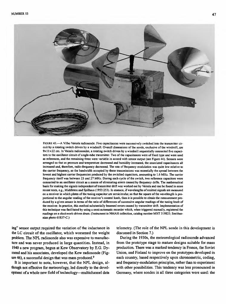
NUMBER 53 47
FIGURE 43.—A Vilho Vaisala radiosonde. Five capacitances were successively switched into the transmitter circuit by a rotating switch driven by a windmill. Overall dimensions of the sonde, exclusive of the windmill, are 9x 11 x22 cm. In Vaisala radiosondes, a rotating switch driven by a windmill sequentially connected five capacitors to the oscillator circuit of single-tube transmitter. Two of the capacitances were of fixed type and were used as references, and the remaining three were variable in accord with sensor output (see Figure 44). Sensors were arranged so that as pressure and temperature decreased and humidity increased, the associated capacitances all increased and, therefore, radio-frequency decreased. The rate of frequency modulation was quite low relative to the carrier frequency, so the bandwidth occupied by these transmissions was essentially the spread between the lowest and highest carrier frequencies produced by the switched capacitors, amounting to 1.6 MHz. The carrier frequency itself was between 23 and 27 MHz. During each cycle of the switch, two reference capacitors were connected to an oscillator circuit as a means of eliminating errors caused by frequency drifts. The mathematical basis for making the signals independent of transmitter drift was worked out by Vaisala and can be found in more recent texts, e.g., Middleton and Spilhaus (1953:253). In essence, if wavelengths of emitted signals are measured on a receiver in which plates of the tuning capacitor are semicircular, so that the square of the wavelength is proportional to the angular reading of the receiver's control knob, then it is possible to obtain the measurement produced by a given sensor in terms of the ratio of differences of successive angular readings of the tuning knob of the receiver. In practice, this method substantially lessened errors caused by transmitter drift. Implementation of this technique was facilitated by using a semi-automatic recorder which, when triggered manually, registered the readings on a clockwork-driven drum. (Instrument in NMAH collection, catalog number MHT 319825; Smithsonian photo 61837-C.)
ing" sensor output required the variation of the inductance in the LC circuit of the oscillator, which worsened the weight problem. The NPL radiosonde also was expensive to manufacture and was never produced in large quantities. Instead, in 1940 a new program, begun at Kew Observatory by E.G. Dy-mond and his associates, developed the Kew radiosonde (Figure 46), a successful design that was mass produced.9
It is important to note, however, that the NPL design, although not effective for meteorology, led directly to the development of a whole new field of technology—multichannel data
telemetry. (The role of the NPL sonde in this development is discussed in Section 7.)
During the 1930s, the meteorological radiosonde advanced from the prototype stage to mature designs suitable for mass production. There was a marked tendency in France, the Soviet Union, and Finland to improve on the prototypes developed in each country, based respectively upon chronometric, coding, and frequency-modulation principles, rather than to experiment with other possibilities. This tendency was less pronounced in Germany, where sondes in all three categories were used: the

48 SMITHSONIAN STUDIES IN HISTORY AND TECHNOLOGY
ay - 5ov.|+ 5ov.
FIGURE 44.—Schematic diagram of a Vaisala radiosonde: 1, barometer housing; 2, thermometer housing; 3, hair hygrometer; 4, variable capacitor of aneroid barometer; 5, variable capacitor of bimetallic thermometer; 6, variable capacitor of hygrometer; 7, 8, reference capacitors, 9, rotary switch. The oscillator, which was frequency modulated by sensors, was a common triode inductive plate-grid feedback type. Note the symmetrical, half-wave antenna required the sonde to be centered between each half of the antenna. (From L. Weickmann, Denkschrift Ober Radiosonden-Konstructionen, Berlin, 1938. Smithsonian photo 63881.)
Askania-Werke and the Lang (chronometric), Duckert (carrier-frequency modulation), and Gaw (coding). Even so, however, the Duckert sonde predominated in Germany and was successively re-engineered over the years.
With regard to cost, the adoption and deployment of any type of radiosonde required training personnel in its use and establishing extensive ground installations. Although the sondes were relatively cheap, the cost of training, of organizational infrastructure, and of ground equipment represented a substantial investment that would be largely lost by a radical change in the sonde. It is significant that in Germany, where different types of sondes were used, a massive military rearmament program was underway during the 1930s.10 Thus, the more ample fund
ing available for satisfying military meteorological needs in Germany may account for the more eclectic approach adopted in that country. In the United States, the chronometric types were developed first, but before any large-scale use was made of them the NBS-Navy sonde (see below) appeared and became the unit of choice. Thus, in the United States the changeover to a radically new design was made before any substantial investment in training and ground equipment had been made.
Another factor that influenced the retention of the original designs was that by 1940 the representative sondes in each category were "good enough."11 This fact, plus the ancillary costs
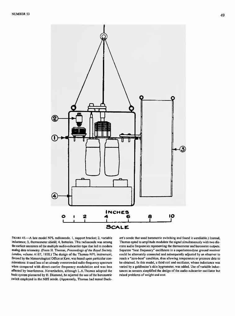
NUMBER 53 49
•-®
SCALE
FIGURE 45.—A late model NPL radiosonde. 1, support bracket; 2, variable inductance; 3, thermometer shield; 4, batteries. This radiosonde was among the earliest ancestors of the multiple audio-subcarrier type that led to modem analog data telemetry. (From H. Thomas, Proceedings of the Royal Society, London, volume A167, 1938.) The design of the Thomas-NPL instrument, favored by the Meteorological Office at Kew, was based upon particular considerations: it used less of an already overcrowded radio-frequency spectrum when compared with direct-carrier frequency modulation and was less affected by interference. Nevertheless, although L.A.Thomas adopted the basic system pioneered by H. Diamond, he rejected the use of the barometric switch employed in the NBS sonde. (Apparently, Thomas had tested Duck-
ert's sonde that used barometric switching and found it unreliable.) Instead, Thomas opted to amplitude modulate the signal simultaneously with two discrete audio frequencies representing the thermometer and barometer outputs. Separate "beat frequency" oscillators in a superheterodyne ground receiver could be alternately connected and subsequently adjusted by an observer to reach a "zero-beat" condition, thus allowing temperature or pressure data to be obtained. In this model, a third coil and oscillator, whose inductance was varied by a goldbeater's skin hygrometer, was added. Use of variable inductances as sensors simplified the design of the audio-subcarrier oscillator but raised problems of weight and cost.
50 SMITHSONIAN STUDIES IN HISTORY AND TECHNOLOGY
FIGURE 46.—British Meteorological Office radiosonde, Kew MK2. The transmitter and batteries are in a black, molded-fiber box, 12 cm in diameter and 23 cm high. The sensors are contained in rectangular aluminum shields mounted on three sides of the box. On the fourth side is a wheel with three conical cups, which revolved in the airstream to operate a switch that connected the three meteorological sensors in sequence. The Kew radiosonde, however, unlike its NPL predecessor, did not continuously transmit signals associated with the three sensors. Instead, the sensors were sequentially switched into the transmitter circuit by means of a rotating contact driven by a windmill. This latter feature was similar to the switching arrangement used in the Vaisala sonde. The fact that signals associated with each sensor were transmitted sequentially meant that only one audio-frequency oscillator was required. This made the sonde lighter and less costly than the NPL model. Also, two of the sensors used in the NPL sonde were redesigned for the Kew model—an aneroid barometer was substituted for the bellows-type, and a resistance-wire thermometer was replaced by a bimetallic type. Until the mid-1930s, the various radiosondes used in the United States were essentially elaborations of the chronometric design. In 1936, however, a radiosonde was developed in the United States that introduced frequency modulation of the audio-frequency subcarrier. In this method, the amplitude of an audio-frequency-tone modulated the radio carrier signal. The tone was then frequency modulated. (Instrument in NMAH collection, catalog number MHT 322313; Smithsonian photo 61906-B.)
in training and equipment, provide a plausible rationale for the course of development from 1931 to 1940 and later.
AMERICAN RADIOSONDES
The radiosonde instruments in the collection cataloged herein came from American institutions, principally from the
United States Weather Bureau. They consist, not surprisingly, of more-or-less final versions of foreign instruments, plus American instruments, most of which never were made in quantity and were considered experimental. In order to make this narrative more comprehensible, we have separated these two categories. Our general history of radiosonde development has been based largely upon "mature" foreign instruments,
NUMBER 53 51
FIGURE 47.—A Blue Hill radiosonde, circa 1935 (from Lange, Bulletin of the American Meteorological Society. volume 17, 1936). As the rotating cylinder, clearly shown in the center, revolved, the wire of the sensor arms sequentially contacted the arms of an aneroid barometer, a bimetallic thermometer, and a hair hygrometer. This arrangement resembled that used by Herath and Robitzch in 1917 and by Bureau in 1929.
leaving for separate discussion the American instruments, about which it is possible to give more detail on experimentation with different designs.
In the United States, the Blue Hill Observatory, near Boston, Massachusetts, produced in 1935 a chronometric radiosonde (Figures 47, 48) that utilized an insulated, clock-driven cylinder with an inset helical wire as the rotating control contact. The next year similar instruments were produced by the Guggenheim Aeronautics Laboratory of the California Institute of Technology (called GALCIT) (Maier and Wood, 1937) and by Friez, an established maker of meteorological instruments in Baltimore, Maryland. Both mechanisms were similar in design to the early Bureau sondes.
The designers of the Blue Hill and GALCIT sondes solved the chronological problem by using special clocks with a relatively large number of discrete movements per revolution. The U.S. Bureau of Standards (NBS) replaced the clocks with small, constant-speed electric motors, including Jacobsen's constant-speed motor (Curtis and Astin, 1935, 1936:358). In 1937, a radiosonde featuring audio-frequency subcarrier modulation was developed at the NBS (Diamond et al., 1938, 1940).
The Americans finally did develop a mature radiosonde. In 1936, the U.S. Navy asked NBS to develop a radiosonde that
FIGURE 48.—A late model of the Blue Hill radiosonde, type F, circa 1936. The small bimetal thermometer, hair hygrometer, and aneroid barometer moved the contact arms along a cylinder, around which were wrapped three turns of a helical conducting wire. The shaft carrying this helix protruded through the top of a light wooden box, which was intended to contain a clock, a radio transmitter, and batteries. The box measures 18x10x7 cm. (From Lange, Bulletin of the American Meteorological Society, volume 18, 1937; see Figure 47; instrument in NMAH collection, catalog number MHT 322324.)
52 SMITHSONIAN STUDIES IN HISTORY AND TECHNOLOGY
FIGURE 49.—Complete receiving and recording equipment for the NBS-Navy radiosonde as it appeared in December 1936. The electronic frequency meter at the center indicated the audio frequencies controlled by the effective values of air pressure, temperature, and humidity, thus revealing the upper-air conditions. (From W. Snyder and Bragaw, Achievement in Radio, 1986.) Coupled with the development of the radiosonde and new sensing elements, the NBS group designed and constructed special ground-station equipment. The complete assembly consisted of a superregenerative receiver coupled to an electronic audio-frequency meter through an amplifier and electrical filter unit. The output of the receiver was applied to the input of a high-speed recording voltmeter. In effect, the assembly converted audio-frequencies into a graphical chart whose abscissa could be calibrated directly in terms of the measured parameters.
would meet the Navy's meteorological requirements. H. Diamond and his associates at NBS organized a well-financed program that produced a superior radiosonde (Diamond et al., 1937). The thermometer used in the first NBS sondes was a small glass tube filled with a nonfreezing electrolyte. This electrolytic temperature sensor could be calibrated to a few tenths of a degree Centigrade and was stable across the range of environmental conditions encountered by the radiosonde. The mechanical sensors used to measure temperature and humidity were inadequate at the higher altitudes attained by these balloons in 1936. This prompted the NBS to develop of electric sensors for both parameters, and the availability of these sensors influenced the design of the NBS-Navy sonde.12
Although the thermistor temperature sensor was available by the late 1930s, when radiosonde production began, it was not sufficiently precise and repeatable to be used at that time. By the early 1950s, however, thermistor development had advanced, and glass-encapsulated types, with long-term stability and precision to less than one degree Centigrade variance, offered sufficient advantage to be used in radiosonde designs.
The first ground receiver was available in early 1938, and service use of the first NBS-U.S. Navy radiosondes (Figure 49) began in the Department of the Navy in June 1938, at the Ana-
costia Naval Air Station in Washington, D.C. (Snyder and Bragaw, 1986:127-129). In 1939-1940, the previously described modifications were made to accommodate the electric hygrometer. By 1940, the design had been refined, and in that year 15,000 such sondes were manufactured (Snyder and Bragaw, 1986:127-129). Many hundreds of thousands were produced in the following years.
An important feature of the sonde was a so-called "pressure drive." Diamond and his colleagues had sought to avoid the complexity and cost entailed by the use of clockwork or electric motors. Some means of switching was required, however, and because they had decided to retain the aneroid barometer as the pressure sensor, they developed a method using its mechanical displacement as a switch, as well as an indication of pressure (Snyder and Bragaw, 1986:127-129). Moreover, meteorologists favored a record in which temperature and humidity were given as functions of pressure. By using the barometer as a switch (Figure 50), such a record could be obtained. To transmit data, a 65-megahertz (MHz) radio signal was amplitude-modulated at an audio frequency of a few hundred cycles per second by a resistance-capacitance (RC) controlled oscillator. Resistive thermometer and hygrometer elements produced
NUMBER 53 53
FIGURE 50.—An electric hygrometer and thermometer assembly used in later NBS-Navy radiosondes, circa 1939. The thermometer is suspended between two arms at the top of the unit; the hygrometer is the upright strip in the center. The hair hygrometer was replaced in later models by a newly developed electric hygrometer. This consisted of a polystyrene strip coated with a film of lithium chloride dissolved in polyvinyl acetate with two tin electrodes sputtered along the long edges of the strip. A combined electrical hygrometer and thermometer were mounted on a single assembly that could be easily attached to the sonde. Replacement of the hair hygrometer with an electric type necessitated circuit changes that involved the use of a relay and a twin-triode vacuum tube, so the final circuit became more complex than that shown in Figure 49, but its essential operation remained the same. (Instrument in NMAH collection, catalog numbers MHT 327975 and 327976; Smithsonian photo 61553.)
a calibrated modulation of this audio-frequency in response to temperature or humidity.
This design was remarkably successful because the meteorological radiosondes used today in the United States still reflect the basic design of the NBS-Navy sonde developed more than half a century ago. The success of the NBS design can be attributed in part to the Navy's insistence on focusing the development on three factors: cost, weight, and accuracy. The sonde was to cost about $25 when purchased in reasonable quantity, and the weight was not to exceed one kilogram. It was to measure temperature to within one degree over the range from plus
40 to minus 75 degrees centigrade, pressure to within one millibar from 1050 to 1500 millibars, and humidity to within three percent from 0 to 100 percent relative humidity. In addition, the U.S. Navy imposed a requirement that significantly affected not only transmitter design, but also the method of signal transmission. The radiosonde was required to emit signals that could be used, in conjunction with radio direction-finding equipment on the ground, to determine wind speed and direction (Snyder and Bragaw, 1986:131).
This last requirement meant that it would be advantageous to have a continuous signal on a constant carrier frequency to fa-
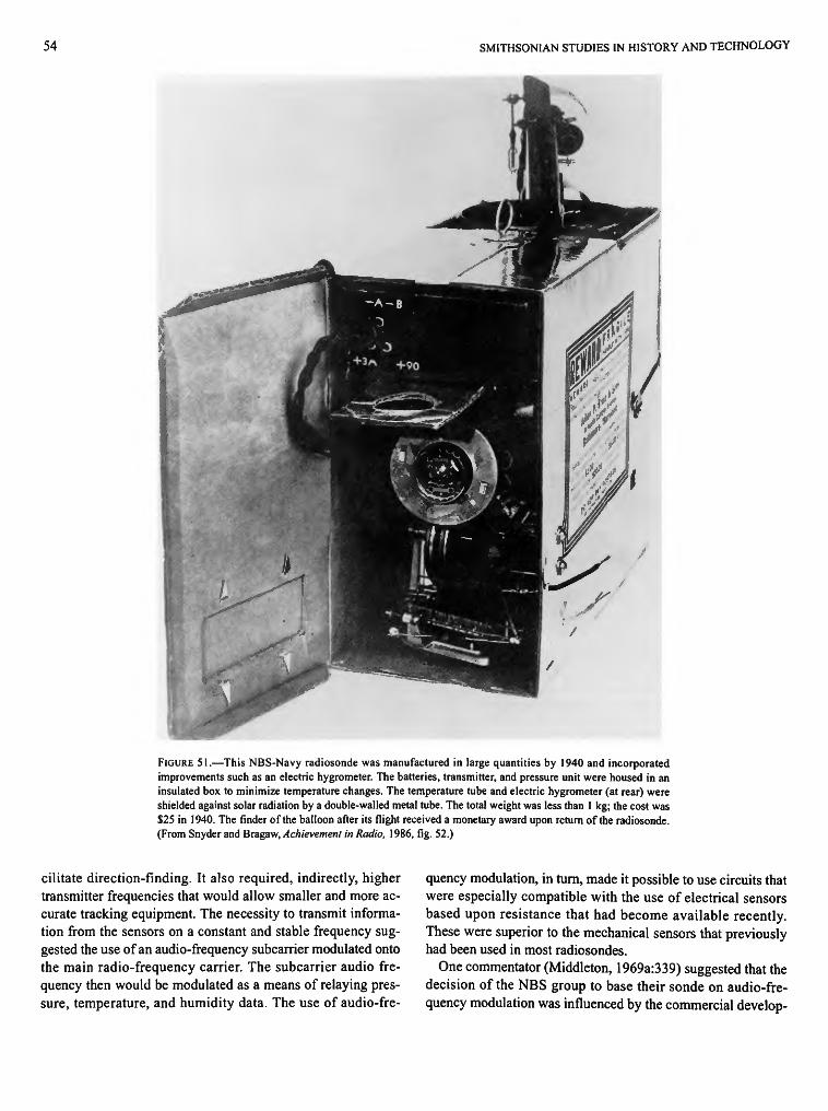
54 SMITHSONIAN STUDIES IN HISTORY AND TECHNOLOGY
FIGURE 51.—This NBS-Navy radiosonde was manufactured in large quantities by 1940 and incorporated improvements such as an electric hygrometer. The batteries, transmitter, and pressure unit were housed in an insulated box to minimize temperature changes. The temperature tube and electric hygrometer (at rear) were shielded against solar radiation by a double-walled metal tube. The total weight was less than 1 kg; the cost was $25 in 1940. The finder of the balloon after its flight received a monetary award upon return of the radiosonde. (From Snyder and Bragaw, Achievement in Radio, 1986, fig. 52.)
cilitate direction-finding. It also required, indirectly, higher transmitter frequencies that would allow smaller and more accurate tracking equipment. The necessity to transmit information from the sensors on a constant and stable frequency suggested the use of an audio-frequency subcarrier modulated onto the main radio-frequency carrier. The subcarrier audio frequency then would be modulated as a means of relaying pressure, temperature, and humidity data. The use of audio-fre
quency modulation, in turn, made it possible to use circuits that were especially compatible with the use of electrical sensors based upon resistance that had become available recently. These were superior to the mechanical sensors that previously had been used in most radiosondes.
One commentator (Middleton, 1969a:339) suggested that the decision of the NBS group to base their sonde on audio-frequency modulation was influenced by the commercial develop-
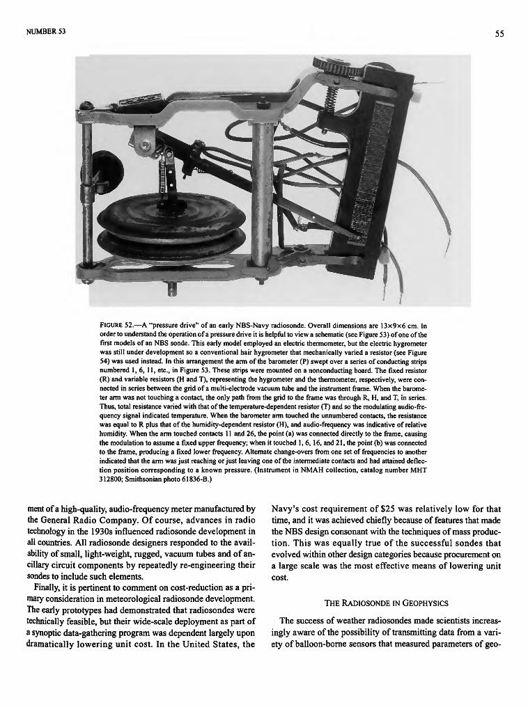
NUMBER 53 55
FIGURE 52.—A "pressure drive" of an early NBS-Navy radiosonde. Overall dimensions are 13x9x6 cm. In order to understand the operation of a pressure drive it is helpful to view a schematic (see Figure 53) of one of the first models of an NBS sonde. This early model employed an electric thermometer, but the electric hygrometer was still under development so a conventional hair hygrometer that mechanically varied a resistor (see Figure 54) was used instead. In this arrangement the arm of the barometer (P) swept over a series of conducting strips numbered 1,6, 11, etc., in Figure 53. These strips were mounted on a nonconducting board. The fixed resistor (R) and variable resistors (H and T), representing the hygrometer and the thermometer, respectively, were connected in series between the grid of a multi-electrode vacuum tube and the instrument frame. When the barometer arm was not touching a contact, the only path from the grid to the frame was through R, H, and T, in series. Thus, total resistance varied with that of the temperature-dependent resistor (T) and so the modulating audio-frequency signal indicated temperature. When the barometer arm touched the unnumbered contacts, the resistance was equal to R plus that of the humidity-dependent resistor (H), and audio-frequency was indicative of relative humidity. When the arm touched contacts 11 and 26, the point (a) was connected directly to the frame, causing the modulation to assume a fixed upper frequency; when it touched 1,6, 16, and 21, the point (b) was connected to the frame, producing a fixed lower frequency. Alternate change-overs from one set of frequencies to another indicated that the arm was just reaching or just leaving one of the intermediate contacts and had attained deflection position corresponding to a known pressure. (Instrument in NMAH collection, catalog number MHT 312800; Smithsonian photo 61836-B.)
ment of a high-quality, audio-frequency meter manufactured by the General Radio Company. Of course, advances in radio technology in the 1930s influenced radiosonde development in all countries. All radiosonde designers responded to the availability of small, light-weight, rugged, vacuum tubes and of ancillary circuit components by repeatedly re-engineering their sondes to include such elements.
Finally, it is pertinent to comment on cost-reduction as a primary consideration in meteorological radiosonde development. The early prototypes had demonstrated that radiosondes were technically feasible, but their wide-scale deployment as part of a synoptic data-gathering program was dependent largely upon dramatically lowering unit cost. In the United States, the
Navy's cost requirement of $25 was relatively low for that time, and it was achieved chiefly because of features that made the NBS design consonant with the techniques of mass production. This was equally true of the successful sondes that evolved within other design categories because procurement on a large scale was the most effective means of lowering unit cost.
THE RADIOSONDE IN GEOPHYSICS
The success of weather radiosondes made scientists increasingly aware of the possibility of transmitting data from a variety of balloon-borne sensors that measured parameters of geo-
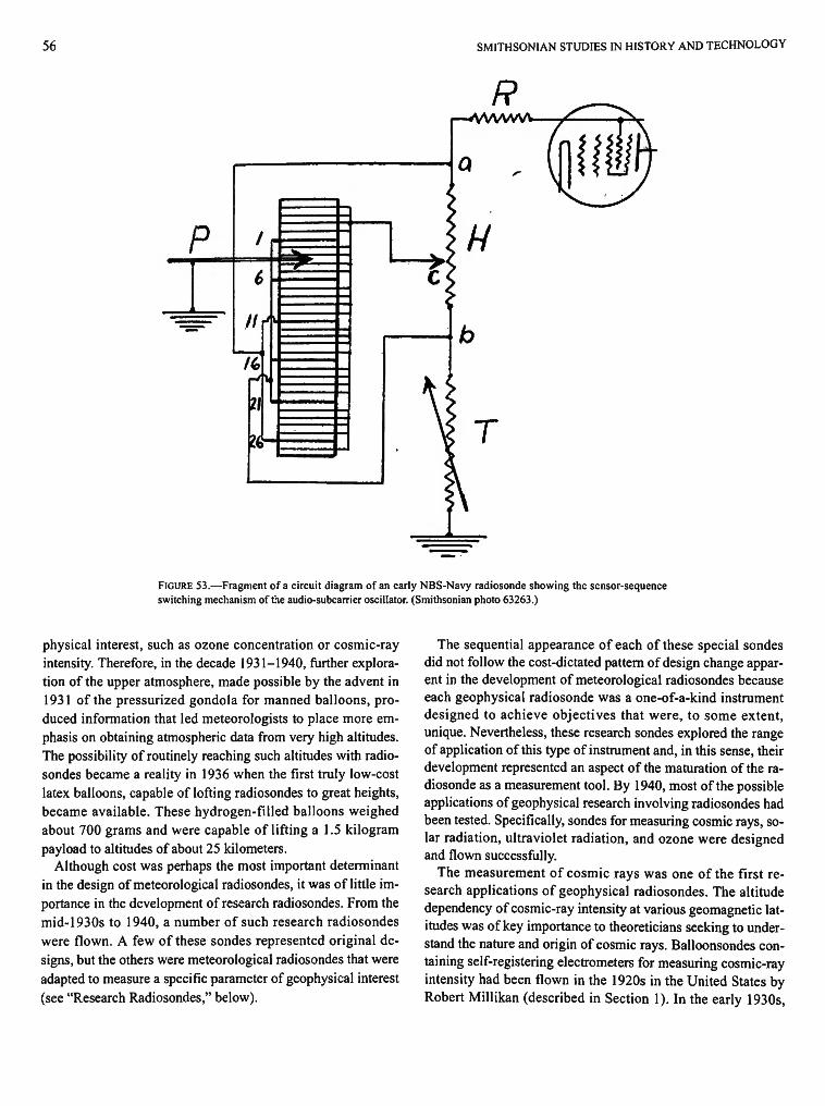
56 SMITHSONIAN STUDIES IN HISTORY AND TECHNOLOGY
R r—*WVWW
P
a
it
H
FIGURE 53.—Fragment of a circuit diagram of an early NBS-Navy radiosonde showing the sensor-sequence switching mechanism of the audio-subcarrier oscillator. (Smithsonian photo 63263.)
physical interest, such as ozone concentration or cosmic-ray intensity. Therefore, in the decade 1931-1940, further exploration of the upper atmosphere, made possible by the advent in 1931 of the pressurized gondola for manned balloons, produced information that led meteorologists to place more emphasis on obtaining atmospheric data from very high altitudes. The possibility of routinely reaching such altitudes with radiosondes became a reality in 1936 when the first truly low-cost latex balloons, capable of lofting radiosondes to great heights, became available. These hydrogen-filled balloons weighed about 700 grams and were capable of lifting a 1.5 kilogram payload to altitudes of about 25 kilometers.
Although cost was perhaps the most important determinant in the design of meteorological radiosondes, it was of little importance in the development of research radiosondes. From the mid-1930s to 1940, a number of such research radiosondes were flown. A few of these sondes represented original designs, but the others were meteorological radiosondes that were adapted to measure a specific parameter of geophysical interest (see "Research Radiosondes," below).
The sequential appearance of each of these special sondes did not follow the cost-dictated pattern of design change apparent in the development of meteorological radiosondes because each geophysical radiosonde was a one-of-a-kind instrument designed to achieve objectives that were, to some extent, unique. Nevertheless, these research sondes explored the range of application of this type of instrument and, in this sense, their development represented an aspect of the maturation of the radiosonde as a measurement tool. By 1940, most of the possible applications of geophysical research involving radiosondes had been tested. Specifically, sondes for measuring cosmic rays, solar radiation, ultraviolet radiation, and ozone were designed and flown successfully.
The measurement of cosmic rays was one of the first research applications of geophysical radiosondes. The altitude dependency of cosmic-ray intensity at various geomagnetic latitudes was of key importance to theoreticians seeking to understand the nature and origin of cosmic rays. Balloonsondes containing self-registering electrometers for measuring cosmic-ray intensity had been flown in the 1920s in the United States by Robert Millikan (described in Section 1). In the early 1930s,
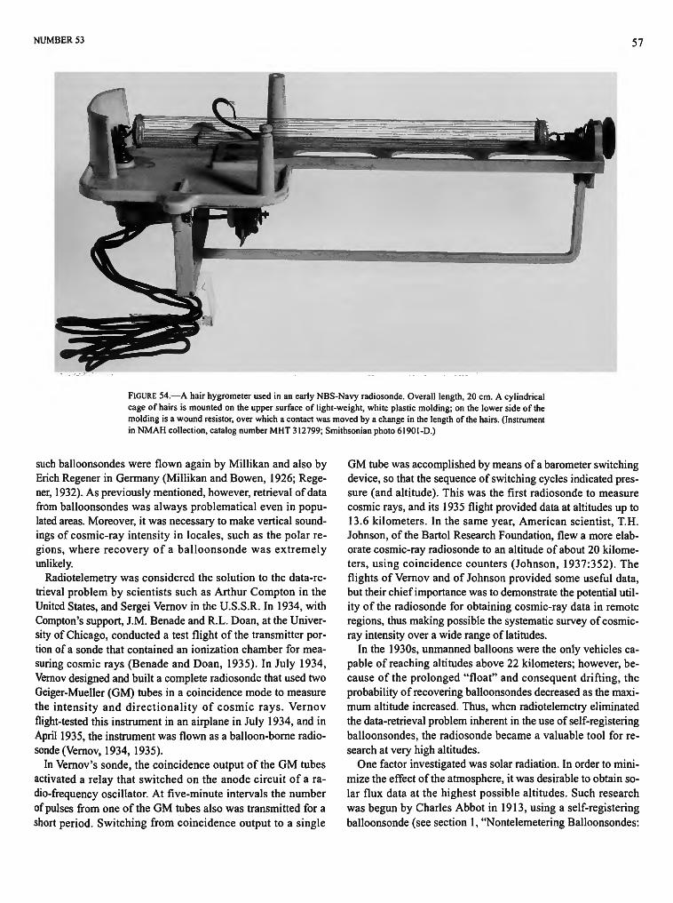
NUMBER 53 57
FIGURE 54.—A hair hygrometer used in an early NBS-Navy radiosonde. Overall length, 20 cm. A cylindrical cage of hairs is mounted on the upper surface of light-weight, white plastic molding; on the lower side of the molding is a wound resistor, over which a contact was moved by a change in the length of the hairs. (Instrument in NMAH collection, catalog number MHT 312799; Smithsonian photo 61901-D.)
such balloonsondes were flown again by Millikan and also by Erich Regener in Germany (Millikan and Bowen, 1926; Rege-ner, 1932). As previously mentioned, however, retrieval of data from balloonsondes was always problematical even in populated areas. Moreover, it was necessary to make vertical soundings of cosmic-ray intensity in locales, such as the polar regions, where recovery of a balloonsonde was extremely unlikely.
Radiotelemetry was considered the solution to the data-retrieval problem by scientists such as Arthur Compton in the United States, and Sergei Vernov in the U.S.S.R. In 1934, with Compton's support, J.M. Benade and R.L. Doan, at the University of Chicago, conducted a test flight of the transmitter portion of a sonde that contained an ionization chamber for measuring cosmic rays (Benade and Doan, 1935). In July 1934, Vemov designed and built a complete radiosonde that used two Geiger-Mueller (GM) tubes in a coincidence mode to measure the intensity and directionality of cosmic rays. Vernov flight-tested this instrument in an airplane in July 1934, and in April 1935, the instrument was flown as a balloon-borne radiosonde (Vemov, 1934, 1935).
In Vernov's sonde, the coincidence output of the GM tubes activated a relay that switched on the anode circuit of a radio-frequency oscillator. At five-minute intervals the number of pulses from one of the GM tubes also was transmitted for a short period. Switching from coincidence output to a single
GM tube was accomplished by means of a barometer switching device, so that the sequence of switching cycles indicated pressure (and altitude). This was the first radiosonde to measure cosmic rays, and its 1935 flight provided data at altitudes up to 13.6 kilometers. In the same year, American scientist, T.H. Johnson, of the Bartol Research Foundation, flew a more elaborate cosmic-ray radiosonde to an altitude of about 20 kilometers, using coincidence counters (Johnson, 1937:352). The flights of Vernov and of Johnson provided some useful data, but their chief importance was to demonstrate the potential utility of the radiosonde for obtaining cosmic-ray data in remote regions, thus making possible the systematic survey of cosmic-ray intensity over a wide range of latitudes.
In the 1930s, unmanned balloons were the only vehicles capable of reaching altitudes above 22 kilometers; however, because of the prolonged "float" and consequent drifting, the probability of recovering balloonsondes decreased as the maximum altitude increased. Thus, when radiotelemetry eliminated the data-retrieval problem inherent in the use of self-registering balloonsondes, the radiosonde became a valuable tool for research at very high altitudes.
One factor investigated was solar radiation. In order to minimize the effect of the atmosphere, it was desirable to obtain solar flux data at the highest possible altitudes. Such research was begun by Charles Abbot in 1913, using a self-registering balloonsonde (see section 1, "Nontelemetering Balloonsondes:
58 SMITHSONIAN STUDIES IN HISTORY AND TECHNOLOGY
1892-1929") (Abbot et al., 1915) and was continued in the United States in 1937 by Brian O'Brien, using a radiosonde. In O'Brien's radiosonde, the light received by a quartz diffuser was passed through a filter that allowed light with the desired spectral characteristics to impinge on a vacuum photocell. The photo current thus generated discharged a capacitance that, upon recharge, caused a radio to transmit a short signal. The rate at which signal pulses were transmitted was proportional to the light incident on the photocell. Two photocell assemblies were used to cover the violet and red portions of the spectrum. In 1937, flights of this radiosonde provided measurements of solar flux to altitudes of about 22 kilometers, with a precision of about one percent. The altitude was determined visually by using a theodolite method (O'Brien et al., 1937). Later flights, involving a comparison of radiosonde data with measurements made simultaneously by ground-based instruments, yielded information on the absolute energy distribution of the solar spectrum (O'Brien, 1939).
Reaching very high altitudes also was important in ascertaining, by extrapolation, the ultraviolet intensity of sunlight beyond the atmosphere. This problem was addressed by W. Coblentz and R.S. Stair at the U.S. National Bureau of Standards, using radiosondes. In the early 1930s, Coblentz developed an ultraviolet-intensity meter based upon a cadmium cathode photocell that was sensitive to radiation in the range of 2600 to 3250 Angstroms. This meter had been used successfully at ground stations to measure ultraviolet radiation and, in 1937, it was modified for use in a radiosonde (Stair and Coblentz, 1938:187). The amplifier and microammeter of the ground-based unit were replaced with a small audio-frequency generator, amplifier, and transmitter that had been designed for the NBS-Navy meteorological radiosonde. The output of the photocell modulated the transmitted audio frequency by changing the voltage on the generator control grid that, in turn, altered the frequency of audio oscillation. The photocell was exposed to sunlight that passed through a series of filters mounted on a rotating wheel. The photocell thus provided sequential measurements of the ultraviolet spectrum. Several flights of this radiosonde were made in the summer of 1937.
Because ozone absorbs ultraviolet radiation, measurement of the ultraviolet intensity at various wavelengths as functions of altitude can be used to determine the concentration of ozone at specific levels of the atmosphere. Stair and Coblentz made additional flights in 1938 with an improved radiosonde to obtain ultraviolet measurements that could be used for determining ozone concentrations. These flights reached altitudes of 27 ki
lometers and ascertained that the ozone layer extended from 18 to 27 kilometers, with the maximum concentration at 25 kilometers (Coblentz and Stair, 1939:573-576). These results confirmed data that had been obtained in the early 1930s by German scientist, Erich Regener, using a balloon-borne, self-registering, ultraviolet spectrometer (Regener and Regener, 1934.
In 1939, cosmic-ray radiosondes were flown by scientists in several countries. In the United States, L. Curtis and A. Astin of NBS measured cosmic rays with a modified version of the NBS-U.S. Navy meteorological sonde. Belgium scientist, M. Cosyns, and British researchers, H. Carmichael and E. Dy-mond, also made flights using cosmic-ray radiosondes of their own design. The flights of Carmichael and Dymond were especially noteworthy because they provided the first vertical soundings of cosmic-ray intensities near the North Pole (Carmichael and Dymond, 1939:323-327).
The polar regions were of great interest to researchers because they realized that theoretical understanding of cosmic rays would be advanced by measuring cosmic-ray intensity over a wide range of geomagnetic latitudes. The sonde developed by Carmichael and Dymond incorporated several GM tubes operated in a coincidence mode to obtain information about the intensity and directionality of cosmic rays. The coincidence output was relayed by the transmitter as a sequence of short pulses. The altitude was derived from pressure measurements, using the method utilized in the Vaisala meteorological radiosonde—an aneroid barometer that varied the spacing of the plates of a capacitance in the tuning circuit of the oscillator of the transmitter, thus altering the radio frequency emitted. In flights made at 85 degrees north latitude, cosmic-ray measurements were obtained at altitudes up to 27 kilometers.
By 1940, the utility of research radiosondes to obtain useful geophysical data from high altitudes had been demonstrated. With the exception of the British polar flights, however, which supplied hitherto unavailable data on cosmic-ray intensity in that region, the data supplied by radiosondes had, for the most part, merely confirmed results on ultraviolet light, ozone, etc., previously gathered with self-registering balloonsondes. As described in the next section, the availability in the 1940s of a practical plastic balloon, capable of reaching heights above 45 kilometers, enhanced the ability of the radiosonde to provide new geophysical data. Consequently, the special sondes of the 1930s became the first in a long succession of research radiosondes that were built to explore the outer reaches of the atmosphere.
7. The Radiosonde after 1940
We have referred to the years 1929-1940 as the period of radiosonde development because the basic designs of meteorological radiosondes did not change radically after 1940. Research in the earlier period also demonstrated the utility of the radiosonde for a variety of geophysical applications, which is discussed in this section.
One of the earliest problems of generating radio signals was frequency control. The defects of a transmitter whose frequency wandered were obscured to some degree by similar defects in receivers. While Blair, Bureau, Vaisala, Duckert, and others struggled with problems of reducing the spurious influences of temperature, humidity, and pressure on their transmitters, so that the calibrated sensors could give accurate readings, improvements in the selectivity of radio reception also made the problem of transmission crucial. Duckert, especially, was concerned with this problem because he was intentionally modulating the transmitter frequency to carry the sensor readings. The desired improvement was achieved by engineers working in other areas of radio transmission, who devised a means of using the extremely stable properties of quartz crystals to control the frequency of a radio-frequency oscillator.
The use of quartz crystals to alleviate transmission problems was never widespread in radiosonde design. Radiosonde designers must have been aware of quartz-crystal circuits since the early 1920s, but they consistently rejected them in favor of simpler radio-frequency oscillators that used less precise methods of stabilization. The reason for this probably was the primary requirements for sonde design—simplicity and low weight. Quartz-crystal frequency control, although elegant and stable, required at least twice the number of components for an equivalent output signal power level. Not until the 1960s, when transistors came into common use in electronic circuitry, did the cost and weight effect of this penalty became less significant.
The post-World War II period brought changes in the design of meteorological radiosondes, although they can perhaps be called evolutionary; that is, whereas engineering modifications were made periodically, in order to exploit advances in electronics and related technologies and to accommodate regulatory requirements of radio spectrum usage, the objectives of meteorological radiosonde design and the methods for achieving these objectives remained relatively unchanged (Dymond, 1947:645-650).
On the other hand, a different situation existed in the case of research radiosondes, where the objectives included the measurement of ozone, cosmic rays, etc., and involved exploitation of the dramatic advances in balloon technology in the 1940s.
At the same time, designers sought to exploit new techniques of multichannel telemetry. Unlike the 1930s, when scientists constructed research sondes by borrowing ideas from the designers of meteorological radiosondes, the increasingly disparate goals of geophysical research and radiosonde design in the post-war world occasioned little of this kind of interaction.
METEOROLOGICAL RADIOSONDES
By 1940, the balloonsonde had been abandoned, and the radiosonde had been adopted by national weather services. The original designs were used for decades, and some are still used today, necessarily changed over the years to incorporate new electronic components and to conform to international regulations controlling the assigned frequency at which transmitters could operate. In general, these changes achieved improved performance at lower cost.
Chronometric Sondes
The Bureau sonde in France and the Jacobsen sonde in Canada were re-engineered periodically to include up-to-date electronic parts. In 1948, the Swiss weather service adopted a chronometric sonde designed by J. Lugeon. This mechanism utilized a clock-driven rotating assembly of the Olland type, but it incorporated a feature that minimized mechanical contact. The sensor arms were terminated in small plates that acted as capacitor plates when positioned above similar plates on the end of the rotating arm. Thus, the position of the arm was indicated by a change in capacitance that altered the transmitted signal (Lugeon et al., 1948:76).
Coding Sondes
The Moltchanoff sonde was progressively redesigned, not only to incorporate new electronic components, but also to improve the mechanics of the coding system. A version that appeared in the 1950s used a simplified coding mechanism consisting of a series of studs arranged in three arcs on an insulating plate over which the arms of the mechanical sensors moved. The position of a given arm was indicated by a windmill-driven mechanism that caused the transmitter to send an identifying code (Anonymous, 1961:101). Coding sondes also were developed in the early 1950s in Japan by K. Isono, and in Germany by H. Hinzpeter (Isono and Huziwara, 1950; Hinz-peter, 1951). A significant feature of the Japanese sonde was the use of two mercury-filled glass thermometers that eliminated the need for a preflight check of the temperature calibra-
59
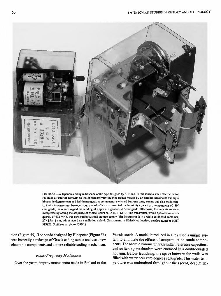
60 SMITHSONIAN STUDIES IN HISTORY AND TECHNOLOGY
FIGURE 55.—A Japanese coding radiosonde of the type designed by K.. Isono. In this sonde a small electric motor revolved a raster of contacts so that it successively touched points moved by an aneroid barometer and by a bimetallic thermometer and hair hygrometer. A commutator switched between these meters and also made contact with two mercury thermometers, one of which disconnected the humidity contact at a temperature of -30° centigrade, the other stopped the sending of a special signal at -50° centigrade. Otherwise, the indications were interpreted by noting the sequence of Morse letters N, D, B, T, M, U. The transmitter, which operated on a frequency of 402 MHz, was powered by a small storage battery. The instrument is in a white cardboard container, 27x15x11 cm, which acted as a radiation shield. (Instrument in NMAH collection, catalog number MHT 319826; Smithsonian photo 65996.)
tion (Figure 55). The sonde designed by Hinzpeter (Figure 56) was basically a redesign of Gaw's coding sonde and used new electronic components and a more reliable coding mechanism.
Radio-Frequency Modulation
Over the years, improvements were made in Finland to the
Vaisala sonde. A model introduced in 1957 used a unique system to eliminate the effects of temperature on sonde components. The aneroid barometer, transmitter, reference capacitors, and switching mechanism were enclosed in a double-walled housing. Before launching, the space between the walls was filled with water near zero degrees centigrade. This water temperature was maintained throughout the ascent, despite de-
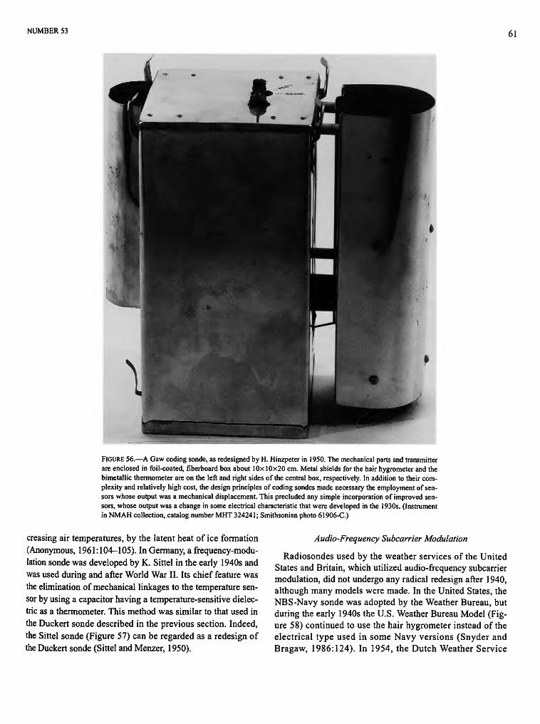
NUMBER 53 61
FIGURE 56.—A Gaw coding sonde, as redesigned by H. Hinzpeter in 1950. The mechanical parts and transmitter are enclosed in foil-coated, fiberboard box about 1 Ox 10x20 cm. Metal shields for the hair hygrometer and the bimetallic thermometer are on the left and right sides of the central box, respectively. In addition to their complexity and relatively high cost, the design principles of coding sondes made necessary the employment of sensors whose output was a mechanical displacement. This precluded any simple incorporation of improved sensors, whose output was a change in some electrical characteristic that were developed in the 1930s. (Instrument in NMAH collection, catalog number MHT 324241; Smithsonian photo 61906-C.)
creasing air temperatures, by the latent heat of ice formation (Anonymous, 1961:104-105). In Germany, a frequency-modulation sonde was developed by K. Sittel in the early 1940s and was used during and after World War II. Its chief feature was the elimination of mechanical linkages to the temperature sensor by using a capacitor having a temperature-sensitive dielectric as a thermometer. This method was similar to that used in the Duckert sonde described in the previous section. Indeed, the Sittel sonde (Figure 57) can be regarded as a redesign of the Duckert sonde (Sittel and Menzer, 1950).
Audio-Frequency Subcarrier Modulation
Radiosondes used by the weather services of the United States and Britain, which utilized audio-frequency subcarrier modulation, did not undergo any radical redesign after 1940, although many models were made. In the United States, the NBS-Navy sonde was adopted by the Weather Bureau, but during the early 1940s the U.S. Weather Bureau Model (Figure 58) continued to use the hair hygrometer instead of the electrical type used in some Navy versions (Snyder and Bragaw, 1986:124). In 1954, the Dutch Weather Service

62 SMITHSONIAN STUDIES IN HISTORY AND TECHNOLOGY
FIGURE 57.—A German radiosonde of the type designed by K. Sittel in which temperature and humidity were determined by a psychrometer. A pressure element and two thermometers—one covered with muslin—were used to vary the frequency of the signal. An electric motor was used to operate a switch that changed the connections among the sensors and two reference capacitors. These, as well as other parts of the transmitter, are contained in a Dewar flask. The entire instrument, except the thermometers, fits into a cylindrical aluminum case, 30 cm long and 8.4 cm in diameter. The thermometers are in an attached triple shield, consisting of an outer oval cylinder. (Instrument in NMAH collection, catalog number MHT 314513; Smithsonian photo 61837-E.)
adopted an audio-subcarrier sonde designed by Dutch scientist A. Hauer (Hauer and van Tol, 1954), which minimized the number of moving parts by adopting the same method used by the NPL in 1938, in which the output from three sensors was represented simultaneously. Three oscillators were required, but by 1954 the availability of subminiature vacuum tubes made the weight penalty of this device less than that of the earlier NPL design (Hauer and van Tol, 1954). In the late 1950s, the cardboard case of the U.S. Weather Bureau sonde was replaced by a plastic case, and in 1960 transistorized radio circuits were introduced (Figure 59). By that time, the transmitting frequency of United States sondes had been increased, first to 400, and then to 1680 megahertz, chiefly to facilitate direction-finding. In 1960, transponders were introduced in some United States models (Figure 60) (Snyder and Bragaw, 1986:131).
The American production model of the 1950s, designated the AN/AMT-4, was a frequency-modulated audio subcarrier type that used amplitude modulation to impress the subcarrier onto the radio-frequency carrier signal. The radio-frequency oscillator was a small "pencil" triode operating in a cavity res
onator and producing about one-half watt of RF power. At 1680 MHz the antenna was small enough to be self-contained in the radiosonde package. The audio subcarrier was produced by a blocking oscillator modulated in the range from 10 to 200 hertz by sensor and reference resistors. These sensors were switched into the modulator circuit in a sequence determined by a NBS baroswitch. Ground equipment automatically received the signal, demodulated the data, and recorded the separate variables on a chart recorder. Later in the decade, the design evolved further, receiving successive model designations AN/AMT4A, AN/AMT4B, etc., but retaining the same basic design (Anonymous, 1961:102).
In the late 1950s and 1960s, additional models appeared with changes in mechanical construction, such as the AN/ AMT11 with a molded plastic case (Figure 59). Other models were designed for special purposes, such as the AN/AMQ-9, a transponding radiosonde (Figure 60). In this type of sonde, a radio receiver picked up signals transmitted from the ground at 403 MHz with pulse modulation at 75 KHz. Meteorological data were added when this signal was received and retransmit-
NUMBER 53 63
FIGURE 58.—A U.S. Weather Bureau radiosonde (left), circa 1942, based upon a NBS-Navy design, is housed in a foil-covered cardboard case, 22x11x22 cm. Two flaps open to reveal an electrolytic thermometer and a cylindrical array of hairs that operated a variable resistor. The hygrometer is mounted on white plastic molding and is enclosed in a semicylindrical white shield with louvers at the upper end. Batteries, a transmitter, and a "baroswitch" occupy the remainder of the carton. A similar sonde is shown (below) with the case cut away to allow most of the components to be seen. (Both instruments in NMAH collection, catalog number MHT 312798, above; catalog number MHT 322315, below; Smithsonian photos 61905-B and 61905, respectively.)
64 SMITHSONIAN STUDIES IN HISTORY AND TECHNOLOGY
FIGURE 59.—A U.S. Weather Bureau radiosonde, circa 1960. This unit is housed in a white plastic box, 12x11.5 x9 cm, and contains a solid-state transmitter and a baroswitch and has brass arms for supporting a thermistor. This radiosonde model transmitted at 1680 MHz frequency and has been in use since the mid-1950s. There is a provision for attaching a battery box. The instrument is marked "Radiosonde set AN/AMT1 IB." (Instrument in NMAH collection, catalog number MHT 324240; Smithsonian photo 61908-C.)
ted back to the ground at 1680 MHz. This system provided a high-data rate from specific locations and altitudes.
The most recent developments in meteorological sondes have incorporated the latest advances in electronics and sensor technology. The trend to higher frequencies, ending with the current international allocation at 1680 megahertz, began during the evolution of radiosonde prototypes in the 1930s. This trend was primarily caused by the need to reduce the size and weight of the devices. Early in the 1940s, a second factor, interference, began to influence the operating frequency of radiosondes. Substantial problems arose from other users of that portion of the radio band in which radiosondes then operated. Ordnance fuses, homing beacons, and communication devices exacerbated the frequency allocation problem. In 1946, the U.S. Federal Communications Commission, working within the framework of an international treaty, allocated a new frequency band, 400 to 406 MHz (71 cm), for radiosonde use. In the United States, the National Bureau of Standards modified its standard design to operate in this range and added an improvement in modulation technique. The latter was pulse modulation, which provided greater accuracy in recovering meteo
rological data. Radiosonde transmitter wavelength remained in the 71 centimeter range for about a decade before moving to the current allocation, in the microwave region, at 17 centimeters.
The evolution of the audio-subcarrier frequency-modulation radiosonde was important to the development of data telemetry. The rapid advance of aviation technology in the late 1920s and 1930s required data transmission from aircraft in flight; measurements of pressure, temperature, electrical current, etc., relating to performance. Until World War II, these quantities were recorded on board the aircraft, using instrumentation similar to early balloon meteorographs. Eventually, however, more immediate readout of the data was required, especially in drone or unmanned test flights where there was a possibility that the vehicle would be damaged or destroyed. The radiosonde provided a well-developed technology that could be adapted for this specific task, transmitting analog electrical and (by transducers) mechanical data over a radio channel from air to ground. There was, however, a problem with straightforward adaptation of radiosonde technology to transmission of data from airplanes to the ground—there was too
NUMBER 53 65
FIGURE 60.—A U.S. Weather Bureau radiosonde with transponder, circa 1965. The plastic case measures 20x 14 x 15 cm and has a tube projecting from the bottom containing a 1680-MHz transmitter and an antenna. The main case contains space for batteries, a clock-driven switch, and a receiver, which received signals from the ground at 403 MHz, pulse-modulated at 75 KHz, and added audio-frequency pulses from meteorological instruments. The output was used to modulate the 1680-MHz transmitter. (Instrument in NMAH collection, catalog number MHT 322310; Smithsonian photo 61905-C.)
much data. Whereas only three variables (temperature, pressure, and humidity) were sufficient to satisfy the needs of the meteorologist using weather balloons, many more variables were needed by the aircraft designer. Even when a single variable, e.g., pressure, was of interest, aviation engineers wanted to measure it at numerous points. Existing radiosonde designs were not equipped to do this. Some unusual attempts were made to overcome this limitation. For example, in World War II, aviation engineers in the United States mounted a television camera in the cockpit to return data by transmitting pictures of a large panel of instrument indicators. Such methods of multiple-channel data transmission were generally unsatisfactory, however, and a more viable technology was needed.
The engineering history of radiosonde development, however, contained a straightforward solution to the multiple-channel data-transmission problem. In 1938, the British NPL expanded the frequency-modulation audio-subcarrier radiosonde to three channels by the simple innovation of using three simultaneous audio frequencies. Each of these audio frequencies was frequency modulated independently by separate data (Thomas, 1938). The underlying theory of radio carrier modulation was highly developed by 1938. (Theory showed the possibility of complex modulation schemes far beyond the existing technology.) It was obvious that three or more audio subcarriers could be modulated simultaneously onto a radio carrier frequency without mutual interference. Although the
British NPL radiosonde was unsuitable for balloon meteorology because of its weight and complexity, it was important as the prototype of a class of instruments used later to solve the problem of massive data retrieval in real time from aircraft and rockets. Multichannel data-telemetry systems, using multiple frequencies, evolved in the late 1940s from this radiosonde technology and became an entirely separate discipline.
RESEARCH RADIOSONDES
In the 1940s, the introduction of multichannel radiotelemetry made feasible the simultaneous transmission of the output of numerous sensors. The development of the plastic balloon also made it possible to loft payloads to altitudes above 45 kilometers. It is noteworthy that these two developments had little effect on meteorological radiosondes because neither the simultaneous transmission of various measurements nor the achievement of such great altitudes were needed by users of such sondes. These advances in radiotelemetry and balloon technology did, however, have a profound influence on the designs of research radiosondes.
Methods of multichannel radio transmission via subcarrier modulation were developed during World War II for various military purposes. Also, the development of multichannel radio telemetry was accelerated in the immediate postwar years by the needs of military rocket programs. Multichannel telem-
66 SMITHSONIAN STUDIES IN HISTORY AND TECHNOLOGY
etry was quickly adopted for research sondes because the capability to transmit simultaneously the output from several sensors was an important consideration in most research applications. For example, cosmic-ray studies usually involved the correlation of atmospheric density with cosmic-ray data. Such correlation was facilitated by obtaining simultaneous outputs from cosmic-ray detectors and from pressure and temperature sensors. Also, in most investigations involving research radiosondes attempts were made to maximize measurement accuracy. Thus, the availability of extra channels to transmit the output of reference standards contributed to the precision of the data. Moreover, the reliability of research sondes was improved by a multichannel capability that allowed redundant sensors to be included in payload designs (Borden and Mayo-Wells, 1959:204-268).
Postwar developments in balloon technology influenced the design of research radiosondes by making it possible to reach altitudes hitherto unexplored by instrumented probes. The origins of this new balloon technology began with the efforts in the early 1930s of German scientist Erich Regener to measure cosmic rays at very high altitudes, using self-registering balloonsondes (Millikan and Bowen, 1926; Regener, 1932). At that time the question of whether "primary" cosmic rays (i.e., the component of such radiation existing outside the earth's atmosphere) were electromagnetic waves or charged particles was still unresolved. Measurements at the highest altitudes attainable could provide information regarding this question, hence, Regener sought design improvements that would allow his balloons to achieve higher altitudes.
It was known that ozone weakened rubber and that rubber balloons usually burst below their maximum theoretical altitude. Regener surmised that the failure of rubber sounding balloons to reach altitudes much greater than 27 kilometers was attributable to the high concentration of ozone between 18 and 27 kilometers. He reasoned that, as balloons passed through the ozone layer, their skin was chemically attacked, causing the balloon to rupture at the weakest point (Regener, 1935). The solution to this problem was to use an ozone-resistant material. In the 1930s, cellophane was the only material available for this purpose, but it lacked flexibility and had undesirable low-temperature characteristics that made it poor material for balloon envelopes. Nevertheless, cellophane balloons were constructed and flown by Regener, probably as early as 1934 .
In 1935, an American scientist, T.H. Johnson, lofted a radiosonde using three cellophane balloons. Johnson's sonde (as dis
cussed in the previous section) was designed to measure cosmic rays. On its first flight it provided data to about 20 kilometers. Johnson had constructed the balloons with the help of another scientist, Jean Piccard (twin brother of August Pic-card, who made the first manned balloon flight into the stratosphere in 1931). In the late 1930s, Jean Piccard conducted additional research on cellophane balloons at the University of Minnesota. The cellophane balloons of the 1930s still did not reach altitudes greater than those attained by rubber balloons because of the unsuitability of cellophane as a balloon material (Pfotzer, 1972:212-226).
After World War II, Piccard, in association with Otto Win-zen, an engineer, persuaded the American firm of General Mills to make polyethelene plastic balloons. The Office of Naval Research (ONR) was sufficiently impressed with the research potential of such balloons that they provided the initial funding to General Mills for the development of a plastic balloon capable of reaching very high altitudes. As a result of the ONR program, the first "Skyhook" balloon was built and flown in September 1947, reaching an altitude of about 30 kilometers. This new technology produced balloons capable of lofting instrument payloads weighing many pounds to altitudes above 45 kilometers, which is above 99.9 percent of the atmosphere surrounding the earth (Pfotzer, 1972:227-231).
During the last four decades, research radiosondes have provided a wealth of information about cosmic rays, atmospheric composition, ultraviolet radiation, and solar flux. Despite the advent of rockets and satellites, balloon-borne research radiosondes still are used because of their unique advantages, relative to other vehicles, primarily low cost and the ability to remain at a given altitude for long periods. Thus, even in the space age, research radiosondes are still a useful investigative tool. Some aspects of rocket flight even depend upon the radiosonde. Winds aloft between about 15 and 45 kilometers must be measured with some precision just before the launch of most types of rocket to insure safe travel through this altitude, where aerodynamic stresses on the vehicle are greatest. It is costly (and for the upper part of this altitude range impossible) to fly airplanes at that altitude to obtain measurements. Consequently, radiosondes are flown prior to virtually all rocket flights to measure wind velocities and other atmospheric parameters that could affect the rocket's ascent. Often launch countdowns are put on "hold" because of adverse radiosonde data.
8. Conclusion
The improvement of agriculture, a paramount economic global concern, was the main objective of meteorology through the nineteenth century. By the end of that century, the art of weather forecasting had made significant progress. Moving air masses were recognized as the carriers of local weather, and data about wind speed and direction, pressure, temperature, and water content (humidity), in one location, were used to forecast the weather elsewhere. It was an imperfect art, and the farmers continued to have more confidence in the Farmer's Almanac.
In the early twentieth century, the emerging technology of aviation provided an additional and urgent need for more accurate weather forecasting. This need assured greater material support for meteorologists, including government financing, because of the obvious military value of aircraft.
The traditional claim of the meteorologist, that the weakness of this science stemmed from insufficient data, was reinforced when the needs of aviation emphasized the limited utility of measurements made from ground level. Unmanned kites and captive balloons were used for decades, but these were limited to relatively low altitude and could not be used in many locations for safety reasons. Observation stations on the tops of mountains and hills provided some limited data. Observations also were made from airplanes, but this was a "chicken and egg" situation—the flights could not be widespread and safe without first having the results of the observations they would be making. As late as 1920, there were very few ways of collecting data from altitudes above a few hundred meters, and no means existed for collecting such data across wide areas in an organized fashion. The advent of heavier-than-air-flying machines worsened the problem because it required the collection of meteorological data at high altitudes on a timely basis. The available technology did not offer the means to satisfy these requirements until the invention of the wireless telegraph (radio). Marconi's transmission of radio signals across the Atlantic, in 1901, provided a solution to the problem of timely collection of meteorological data, which was used three decades later.
The speed with which these components were put together to create the radiosonde was remarkable. It hardly involved any advance in science, but rather the appearance of an urgent need, aviation. Nor was technological innovation very conspicuous. Important factors were the concurrent emergence of a popular hobby—amateur radio—and the commercial availability of vacuum tubes and other components. Finally, there was that never-failing stimulus to development—military application.
All this seems obvious now. The successful development of the radiosonde tends to hide the complexity of the research by which it was produced. The radiosonde represented one of the
first comprehensive applications of radio to a purpose other than communication. This use of radio technology to meet a remote-sensing requirement was not unique, but it did set a precedent that accounts for some aspects of the history of subsequent instrumentation.
There also were important consequences for the then backward science of meteorology. Thanks to data provided by the radiosonde from a range of altitudes, synoptic weather maps were vastly improved. These data, in turn, provided the means to generate timely, accurate forecasts based upon the motion and evolution of the air masses. As radiosonde technology and data collection improved in the 1940s, scientific meteorology finally matured. Deterministic modeling of the atmosphere, based upon the physical laws of gas dynamics and heat transfer, although appropriate, had long been considered futile because measurements on a sufficiently large scale and at high enough resolution to establish initial conditions for the equations could not be made. The availability of large amounts of data from radiosondes and the emergence of electronic computers in the late 1940s helped to forge a new branch of science in practical modeling of the atmosphere. Modeling, together with skillful interpretation of data, has promoted a steady improvement in our understanding of the atmosphere and its dynamics.
From the perspective of the history of technology, the radiosonde also served as an important link in the development of multichannel radio transmission, using subcarrier modulation. Because this became the basis of modern analog radiotelemetry systems, the development of the radiosonde represented an important phase in the history of telemetry.
Ground observations continue to be important, but they provide only a small portion of the necessary data. Atmospheric data collection by satellite, starting with the NIMBUS and TIROS programs in the 1960s and 1970s, is now supplementing radiosonde data. Satellites have not yet completely replaced the radiosonde, however, because of the difficulty of obtaining vertical measurements from the overhead view of a satellite. Techniques to accomplish high-resolution vertical profiling of atmospheric temperature by infrared radiotelemetry have been refined in successive generations of TIROS (now called NOAA) and other weather satellites. Additional parameters, such as wind vectors and barometric pressure, also can be determined from satellites, but to a lesser degree of precision than by radiosondes. Nevertheless, it is likely that, by some time in the twenty-first century, the majority of radiosonde data collection will be replaced by satellite-derived measurements, and radiosonde deployment will be relegated to a minor, niche technique.
67
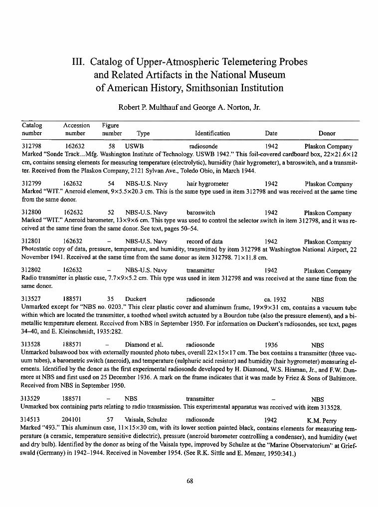
III. Catalog of Upper-Atmospheric Telemetering Probes and Related Artifacts in the National Museum of American History, Smithsonian Institution
Robert P. Multhauf and George A. Norton, Jr.
Catalog number
Accession number
Figure number Type Identification Date Donor
312798 162632 58 USWB radiosonde 1942 Plaskon Company Marked "Sonde Track... Mfg. Washington Institute of Technology. USWB 1942." This foil-covered cardboard box, 22x21.6x12 cm, contains sensing elements for measuring temperature (electrolytic), humidity (hair hygrometer), a baroswitch, and a transmitter. Received from the Plaskon Company, 2121 Sylvan Ave., Toledo Ohio, in March 1944.
312799 162632 54 NBS-U.S. Navy hair hygrometer 1942 Plaskon Company Marked "WIT." Aneroid element, 9x5.5x20.3 cm. This is the same type used in item 312798 and was received at the same time from the same donor.
312800 162632 52 NBS-U.S. Navy baroswitch 1942 Plaskon Company Marked "WIT." Aneroid barometer, 13x9x6 cm. This type was used to control the selector switch in item 312798, and it was received at the same time from the same donor. See text, pages 50-54.
312801 162632 NBS-U.S. Navy record of data 1942 Plaskon Company Photostatic copy of data, pressure, temperature, and humidity, transmitted by item 312798 at Washington National Airport, 22 November 1941. Received at the same time from the same donor as item 312798. 71x11.8 cm.
312802 162632 NBS-U.S. Navy transmitter 1942 Plaskon Company Radio transmitter in plastic case, 7.7x9x5.2 cm. This type was used in item 312798 and was received at the same time from the same donor.
313527 188571 35 Duckert radiosonde ca. 1932 NBS Unmarked except for "NBS no. 0203." This clear plastic cover and aluminum frame, 19x9x31 cm, contains a vacuum tube within which are located the transmitter, a toothed wheel switch actuated by a Bourdon tube (also the pressure element), and a bimetallic temperature element. Received from NBS in September 1950. For information on Duckert's radiosondes, see text, pages 34-40, and E. Kleinschmidt, 1935:282.
313528 188571 Diamond et al. radiosonde 1936 NBS Unmarked balsawood box with externally mounted photo tubes, overall 22x 15x 17 cm. The box contains a transmitter (three vacuum tubes), a barometric switch (aneroid), and temperature (sulphuric acid resistor) and humidity (hair hygrometer) measuring elements. Identified by the donor as the first experimental radiosonde developed by H. Diamond, W.S. Hinman, Jr., and F.W. Dun-more at NBS and first used on 25 December 1936. A mark on the frame indicates that it was made by Friez & Sons of Baltimore. Received from NBS in September 1950.
313529 188571 - NBS transmitter - NBS Unmarked box containing parts relating to radio transmission. This experimental apparatus was received with item 313528.
314513 204101 57 Vaisala, Schulze radiosonde 1942 K.M.Perry Marked "493." This aluminum case, 11 x 15x30 cm, with its lower section painted black, contains elements for measuring temperature (a ceramic, temperature sensitive dielectric), pressure (aneroid barometer controlling a condenser), and humidity (wet and dry bulb). Identified by the donor as being of the Vaisala type, improved by Schulze at the "Marine Observatorium" at Grief-swald (Germany) in 1942-1944. Received in November 1954. (See R.K. Sittle and E. Menzer, 1950:341.)
68

NUMBER 53 69
Catalog Accession Figure number number number Type Identification Date Donor
314514 204101 - unknown radiosonde K.M.Perry Marked "61426," and bearing a stamp indicating a German origin. The brown fibre case, 10.4x14.3x20 cm, has metal ends and contains bimetallic thermometric and aneroid barometric elements. Received in November 1954.
314677 209614 USWB radiosonde 1955 USWB Marked "Northeastern Engineering, Inc.," with USWB serial no. 509401. The white cardboard carton (cut away), 20x23x 12 cm, contains a variable audio-frequency transmitter, a thermistor, and an electric hygrometer. This instrument was used on 13 July 1955 and was found, after ascending to a height of 32 kilometers, at Redwater Alta, Saskatchewan, Canada.
316262 224564 32 Moltchanoff radiosonde ca. 1935 USWB Marked "39097." The brown cardboard case, 7x27x33 cm, contains elements for measuring temperature (bimetallic), pressure (Bourdon tube), and humidity (hair hygrometer). It incorporates a rotating contact of the Olland type. The transmitter is missing. For information on Moltchanoff's instruments, see text, pages 33 and 34, and Lange, 1935:286. Received in March 1959.
317728 231230 - USWB radiosonde 1960 USWB Marked "Ray Sonde Bendix." This blue and white cardboard box, 11.4x18x20.3 cm, contains elements for measuring temperature (electrolytic) and humidity (electrolytic), and a barometric switch. Received in June 1960 and identified by the donor as a contemporary instrument.
319744 239017 NBS radiosonde 1940 E.L. Reilly Marked "Sonde Track. Mfg. in USA by Washington Institute of Technology," and the inspection date 9/25/40. The two nested cardboard boxes, 11x25.4x22 cm, enclose elements for measuring temperature (electrolytic), pressure (aneroid), and humidity (hair hygrometer), all reportedly developed at the NBS. Identified by the donor as WIT Sonde Track no. 1, produced on 25 September 1940, flown at Oklahoma City on 1 October, and recovered 13 October at Presque, Oklahoma. This is an example of the NBS variable audio-frequency radiosonde. Received November 1961.
319824 240347 - (British) radiosonde 71937 USWB Marked "D698." Elements for measuring temperature (bimetallic), pressure (aneroid), and humidity (goldbeater's skin) project from the sides of a cardboard cylinder 13 cm in diameter by 14 cm long. Incomplete. Identified by the donor as a British instrument. Received in January 1962. (See Lange, 1937.)
319825 240347 43 Vaisala radiosonde ca. 1950 USWB Marked "180140." The aluminum box, 9x31x18 cm, contains elements for measuring temperature (bimetallic), pressure (aneroid), and humidity (hair hygrometer), and incorporates a windmill-operated selector switch. (See text, pages 46^48, and item 314513.) Received January 1962 and dated by the donor as being from about 1950.
319826 240347 55 - Japanese radiosonde ca. 1960 USWB Marked "CMO-S50L" and stamped "DNPA No. 4552, Japan. Type Approval, Radio Regulatory Commission" (with additional label in Japanese). This white box of corrugated paper, 28x 12x 16 cm, contains elements for measuring temperature (two mercury and one bimetallic thermometers), pressure (aneroid), and humidity (hair hygrometer). Received in January 1962.
319827 240347 30 Bureau radiosonde ca. 1932 USWB Marked "Constructions Mecaniques et Electriques P. de Presale, 104-106, Rue Oberkampf, Paris (XI) Type PTU (Sereal) 3567." The aluminum foil covered box, 27x 16x 14 cm, contains a transmitter (vacuum tube and batteries missing) and elements for measuring temperature (bimetallic), pressure (bourdon tube), and humidity (hair hygrometer). Temperature and pressure were indicated by interruptions in the transmitting signal. For information on Bureau's instruments see text, pages 31-36. Received in January 1962.
319828 240347 - Cal. Inst. Tech. radiosonde ca. 1935 USWB Unmarked, but tagged by donor "Composite California Institute of Technology type." This instrument, 10x15x24 cm, contains elements for measuring temperature (bimetallic), pressure (aneroid), and humidity (hair hygrometer), and a clock-driven selector switch. Received January 1962.
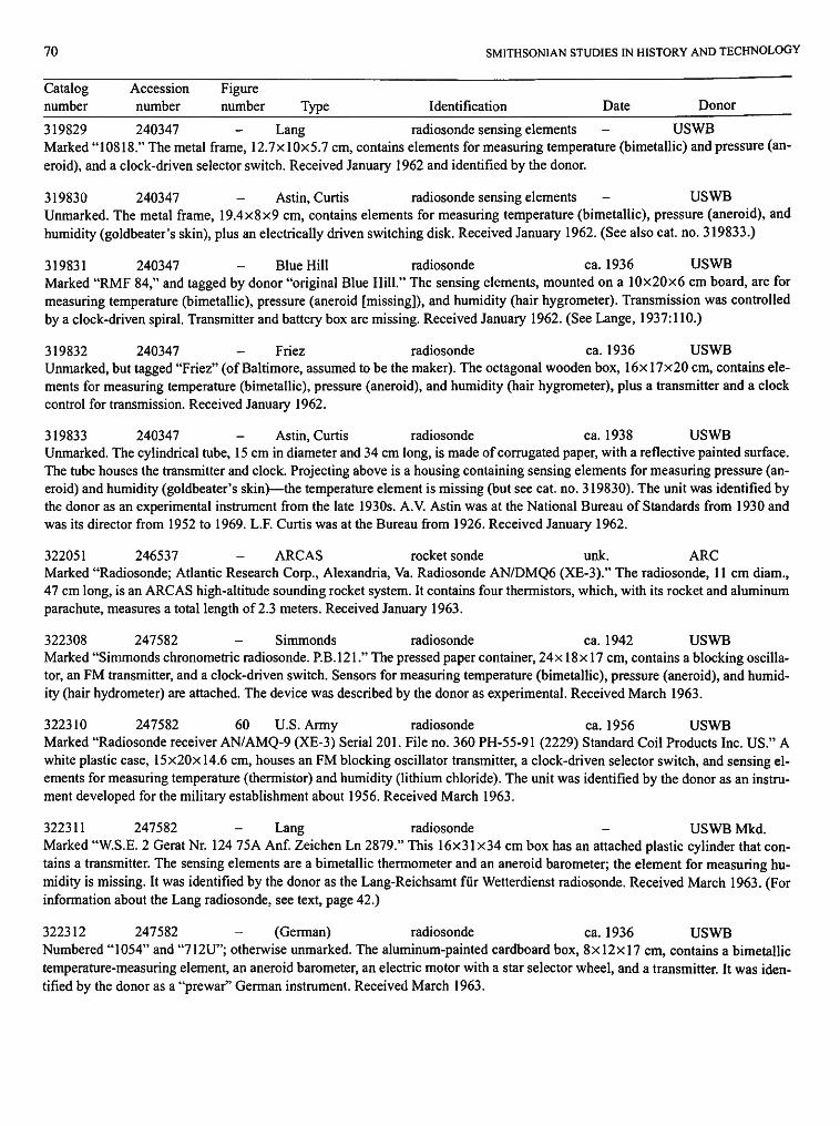
70 SMITHSONIAN STUDIES IN HISTORY AND TECHNOLOGY
Catalog Accession Figure number number number Type Identification Date Donor
319829 240347 - Lang radiosonde sensing elements - USWB Marked "10818." The metal frame, 12.7x 10x5.7 cm, contains elements for measuring temperature (bimetallic) and pressure (aneroid), and a clock-driven selector switch. Received January 1962 and identified by the donor.
319830 240347 Astin, Curtis radiosonde sensing elements - USWB Unmarked. The metal frame, 19.4x8x9 cm, contains elements for measuring temperature (bimetallic), pressure (aneroid), and humidity (goldbeater's skin), plus an electrically driven switching disk. Received January 1962. (See also cat. no. 319833.)
319831 240347 Blue Hill radiosonde ca. 1936 USWB Marked "RMF 84," and tagged by donor "original Blue Hill." The sensing elements, mounted on a 10x20x6 cm board, are for measuring temperature (bimetallic), pressure (aneroid [missing]), and humidity (hair hygrometer). Transmission was controlled by a clock-driven spiral. Transmitter and battery box are missing. Received January 1962. (See Lange, 1937:110.)
319832 240347 - Friez radiosonde ca. 1936 USWB Unmarked, but tagged "Friez" (of Baltimore, assumed to be the maker). The octagonal wooden box, 16x 17x20 cm, contains elements for measuring temperature (bimetallic), pressure (aneroid), and humidity (hair hygrometer), plus a transmitter and a clock control for transmission. Received January 1962.
319833 240347 Astin, Curtis radiosonde ca. 1938 USWB Unmarked. The cylindrical tube, 15 cm in diameter and 34 cm long, is made of corrugated paper, with a reflective painted surface. The tube houses the transmitter and clock. Projecting above is a housing containing sensing elements for measuring pressure (aneroid) and humidity (goldbeater's skin)—the temperature element is missing (but see cat. no. 319830). The unit was identified by the donor as an experimental instrument from the late 1930s. A.V. Astin was at the National Bureau of Standards from 1930 and was its director from 1952 to 1969. L.F. Curtis was at the Bureau from 1926. Received January 1962.
322051 246537 ARCAS rocket sonde unk. ARC Marked "Radiosonde; Atlantic Research Corp., Alexandria, Va. Radiosonde AN/DMQ6 (XE-3)." The radiosonde, 11 cm diam., 47 cm long, is an ARCAS high-altitude sounding rocket system. It contains four thermistors, which, with its rocket and aluminum parachute, measures a total length of 2.3 meters. Received January 1963.
322308 247582 Simmonds radiosonde ca. 1942 USWB Marked "Simmonds chronometric radiosonde. P.B.I21." The pressed paper container, 24x 18x 17 cm, contains a blocking oscillator, an FM transmitter, and a clock-driven switch. Sensors for measuring temperature (bimetallic), pressure (aneroid), and humidity (hair hydrometer) are attached. The device was described by the donor as experimental. Received March 1963.
322310 247582 60 U.S. Army radiosonde ca. 1956 USWB Marked "Radiosonde receiver AN/AMQ-9 (XE-3) Serial 201. File no. 360 PH-55-91 (2229) Standard Coil Products Inc. US." A white plastic case, 15x20x 14.6 cm, houses an FM blocking oscillator transmitter, a clock-driven selector switch, and sensing elements for measuring temperature (thermistor) and humidity (lithium chloride). The unit was identified by the donor as an instrument developed for the military establishment about 1956. Received March 1963.
322311 247582 Lang radiosonde - USWB Mkd. Marked "W.S.E. 2 Gerat Nr. 124 75A Anf. Zeichen Ln 2879." This 16x31 x34 cm box has an attached plastic cylinder that contains a transmitter. The sensing elements are a bimetallic thermometer and an aneroid barometer; the element for measuring humidity is missing. It was identified by the donor as the Lang-Reichsamt fur Wetterdienst radiosonde. Received March 1963. (For information about the Lang radiosonde, see text, page 42.)
322312 247582 (German) radiosonde ca. 1936 USWB Numbered "1054" and "712U"; otherwise unmarked. The aluminum-painted cardboard box, 8x12x17 cm, contains a bimetallic temperature-measuring element, an aneroid barometer, an electric motor with a star selector wheel, and a transmitter. It was identified by the donor as a "prewar" German instrument. Received March 1963.
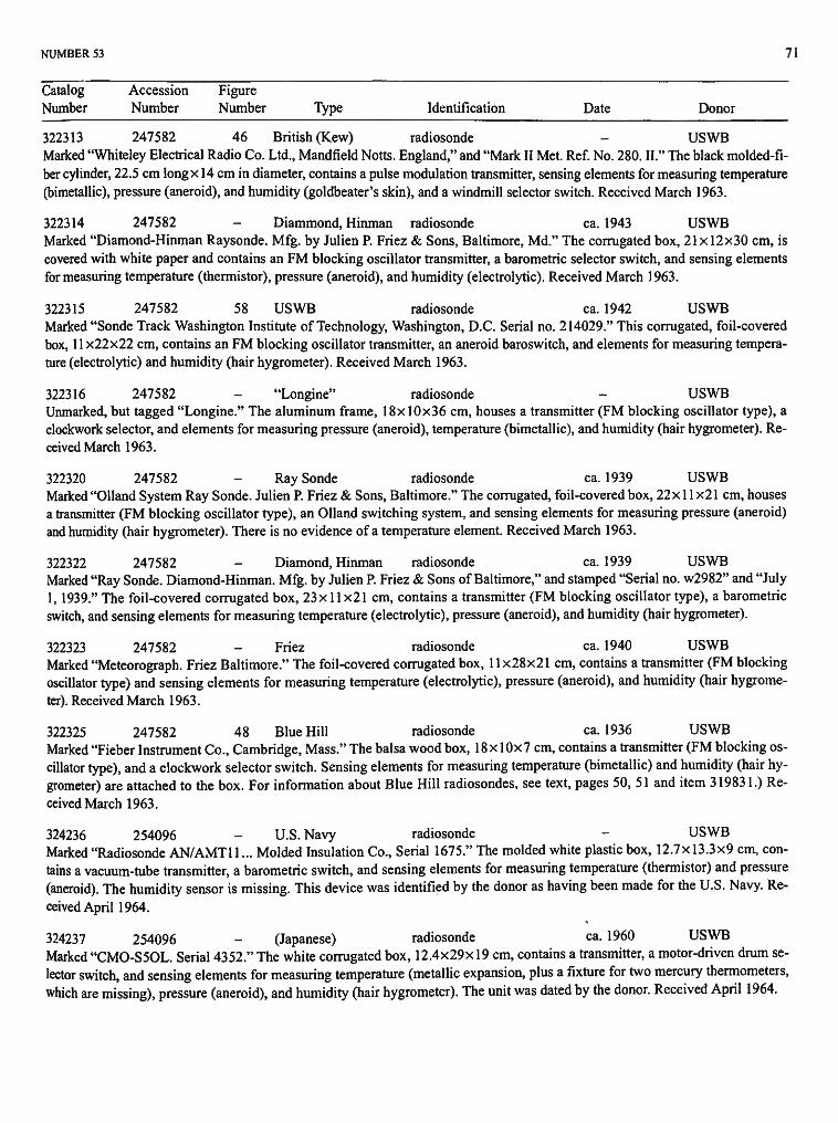
NUMBER 53 71
Catalog Accession Figure Number Number Number Type Identification Date Donor
322313 247582 46 British (Kew) radiosonde - USWB Marked "Whiteley Electrical Radio Co. Ltd., Mandfield Notts. England," and "Mark II Met. Ref. No. 280. II." The black molded-fi-ber cylinder, 22.5 cm long x 14 cm in diameter, contains a pulse modulation transmitter, sensing elements for measuring temperature (bimetallic), pressure (aneroid), and humidity (goldbeater's skin), and a windmill selector switch. Received March 1963.
322314 247582 Diammond, Hinman radiosonde ca. 1943 USWB Marked "Diamond-Hinman Raysonde. Mfg. by Julien P. Friez & Sons, Baltimore, Md." The corrugated box, 21 x 12x30 cm, is covered with white paper and contains an FM blocking oscillator transmitter, a barometric selector switch, and sensing elements for measuring temperature (thermistor), pressure (aneroid), and humidity (electrolytic). Received March 1963.
322315 247582 58 USWB radiosonde ca. 1942 USWB Marked "Sonde Track Washington Institute of Technology, Washington, D.C. Serial no. 214029." This corrugated, foil-covered box, 11x22x22 cm, contains an FM blocking oscillator transmitter, an aneroid baroswitch, and elements for measuring temperature (electrolytic) and humidity (hair hygrometer). Received March 1963.
322316 247582 "Longine" radiosonde USWB Unmarked, but tagged "Longine." The aluminum frame, 18x 10x36 cm, houses a transmitter (FM blocking oscillator type), a clockwork selector, and elements for measuring pressure (aneroid), temperature (bimetallic), and humidity (hair hygrometer). Received March 1963.
322320 247582 Ray Sonde radiosonde ca. 1939 USWB Marked "Olland System Ray Sonde. Julien P. Friez & Sons, Baltimore." The corrugated, foil-covered box, 22x 11 x21 cm, houses a transmitter (FM blocking oscillator type), an Olland switching system, and sensing elements for measuring pressure (aneroid) and humidity (hair hygrometer). There is no evidence of a temperature element. Received March 1963.
322322 247582 Diamond, Hinman radiosonde ca. 1939 USWB Marked "Ray Sonde. Diamond-Hinman. Mfg. by Julien P. Friez & Sons of Baltimore," and stamped "Serial no. w2982" and "July 1, 1939." The foil-covered corrugated box, 23x11x21 cm, contains a transmitter (FM blocking oscillator type), a barometric switch, and sensing elements for measuring temperature (electrolytic), pressure (aneroid), and humidity (hair hygrometer).
322323 247582 - Friez radiosonde ca. 1940 USWB Marked "Meteorograph. Friez Baltimore." The foil-covered corrugated box, 11 x28x21 cm, contains a transmitter (FM blocking oscillator type) and sensing elements for measuring temperature (electrolytic), pressure (aneroid), and humidity (hair hygrometer). Received March 1963.
322325 247582 48 Blue Hill radiosonde ca. 1936 USWB Marked "Fieber Instrument Co., Cambridge, Mass." The balsa wood box, 18x 10x7 cm, contains a transmitter (FM blocking oscillator type), and a clockwork selector switch. Sensing elements for measuring temperature (bimetallic) and humidity (hair hygrometer) are attached to the box. For information about Blue Hill radiosondes, see text, pages 50, 51 and item 319831.) Received March 1963.
324236 254096 - U.S. Navy radiosonde USWB Marked "Radiosonde AN/AMT11... Molded Insulation Co., Serial 1675." The molded white plastic box, 12.7x 13.3x9 cm, contains a vacuum-tube transmitter, a barometric switch, and sensing elements for measuring temperature (thermistor) and pressure (aneroid). The humidity sensor is missing. This device was identified by the donor as having been made for the U.S. Navy. Received April 1964.
324237 254096 - (Japanese) radiosonde ca. 1960 USWB Marked "CMO-S50L. Serial 4352." The white corrugated box, 12.4x29x 19 cm, contains a transmitter, a motor-driven drum selector switch, and sensing elements for measuring temperature (metallic expansion, plus a fixture for two mercury thermometers, which are missing), pressure (aneroid), and humidity (hair hygrometer). The unit was dated by the donor. Received April 1964.

72 SMITHSONIAN STUDIES IN HISTORY AND TECHNOLOGY
Catalog Accession Figure Number Number Number Type Identification Date Donor
324238 254096 USWB radiosonde 1963 USWB Marked "USWB-Molded Insulation Co., Phila. Serial 37-00006," and stamped "Feb. 8, 1963." This corrugated, paper-covered box, 13x 16x 12 cm, contains a transmitter, a barometric switch, and sensing elements for measuring temperature (thermistor) and pressure (aneroid). The humidity sensor is missing. Received April 1964.
324239 254096 (Japanese) radiosonde 1945 USWB Marked in Japanese, and with serial no. "020918." The white cylindrical plastic case, 16.5 cm longxll cm in diameter, contains sensing elements for measuring temperature (mercury thermometer [broken]), pressure (aneroid), and humidity (hair hygrometer), each with its own vacuum tube, circuitry, and antenna. The device was dated by the donor. Received April 1964.
324240 254096 59 U.S. Navy radiosonde USWB Marked "Radiosonde set AN/AMT 11 B... Molded Insulation Co." The white plastic box, 12.4x13.7x10 cm, contains a solid-state transmitter, a barometric switch, and a sensing element for measuring temperature (thermistor). The humidity element is missing. This device was identified by the donor as one that was intended to be expendable. Received April 1964.
324241 254096 56 Gaw (German) radiosonde 1963 USWB Marked "Transport Aufstieg. 5821." This foil-covered cardboard box, 1 Ox 10x20 cm, contains a transmitter, a motor-driven selector switch, and sensing elements for measuring temperature (bimetallic), pressure (aneroid), and humidity (hair hygrometer). Received April 1964. (For further information, see text, pages 60, 61.)
324242 254096 - USWB thermistor ca. 1960 USWB Unmarked. This temperature measuring element consists of a wire coated with lead monoxide that is housed within a glass tube. This improvement in temperature measurement was developed at Johns Hopkins University about 1946 under contract with the USWB. (See Brasefield, 1948:145-151.)
327975 254096 50 NBS-U.S. Navy thermometer/hygrometer The thermistor and electrolytic hygrometer assembly are mounted on a bakelite board. Overall dimensions are 11 x 12.7x74 cm. It was probably experimental. Received October 1966.
Uncataloged - - USWB temperature element 1957 -Unmarked but labeled "Temperature element ML-419/AMT-4. Molded Insulation Company, US," and stamped "Feb. 1957." This wire element in a glass vial was probably an experimental thermistor from the USWB, although the source is unknown.
Uncataloged - USWB hygristor 1959 The small can is stamped "USWB hygristor, electric hygrometer element. Model no. 524318-3. Bendix Aviation Corp., Friez Instrument Division, Baltimore, Md." and is dated 16 July 1959. It was probably from the USWB.

Notes
1. The hair hygrometer measures relative humidity in terms of dimensional changes on one or more human hairs stretched on a frame. It was invented in 1793 by French scientist Horace de Saussure, and by 1820 it had become widely used in meteorological research. By the 1890s, hair hygrometers were highly developed as sensors for humidity.
2. Charles' balloon was filled with hydrogen. An alternative gas-fill appeared in the early 1800s when "coal gas" (chiefly a mixture of hydrogen and methane) began to be produced by municipal gas works for fueling the street lamps of many European cities. Coal gas was first used in a balloon in 1821, and although it has only half the lifting power of hydrogen its much lower cost and ready availability made it the gas of choice for balloon use. The unmanned balloons used by Hermite and other meteorological investigators generally were filled with coal gas.
3. Letter from Millikan to W. Blair, Millikan Papers, 28 November 1922, Roll 23, Folder 23.1. Library of the National Museum of American History, Smithsonian Institution.
4. The concept of entrainment in a complex system actually predates Olland, Bain, telemetry, and computers by at least a billion years, having been worked out by Darwinian evolution on living organisms in response to the survival advantage of photoperiodic behavior. Virtually all living organisms exhibit a cyclic pattern of motor or biochemical behavior, which is entrained to the solar photoperiod. If such an organism is studied under conditions where environmental light and other geophysical parameters are held constant, the behavior cycle will usually continue at a period different from the 24-hour solar period. Under natural conditions the solar photoperiod resets the behavior cycle once per period, which synchronizes the sender (sun) with the receiver (organism).
5. Radio wavelength is an important parameter. It determines, to a large degree, the size and weight of transmitter components as well as the antenna. Also, before World War I, radio-band usage was not regulated by governments or international treaty and, being in the same range as other users, there was considerable chance for interference. The earliest radiosondes of Blair and of Bureau adapted radio frequency transmission circuits directly from the technology of contemporary radio telegraphy and radio telephony. Blair's first transmitter used a wavelength of 125 meters (2.3 MHz) in 1924 (Blair and Lewis, 1931:1532) and Bureau's 1929 radiosonde operated at about 60 meters (4.8 MHz) (Bureau, 1931).
The early investigators were aware of the potential advantages of shorter wavelengths, but they faced substantial technological barriers to using short waves. Transmitter circuitry and vacuum tubes that were small and would operate reliably at wavelengths below about 20 meters were not well developed in the mid-1930s. In spite of this, the advantages were great enough that, starting with Blair at 125 meters, there was an evolution toward the shorter wavelengths that continued though the 1950s to 17 centimeters (1680 MHz) where current radiosondes operate. This evolution can be traced through the first two decades of radiosonde development. First, Bureau settled on a shorter wavelength than Blair, 60 meters, and was able to shorten his antenna considerably. The United States program, starting in 1935 at the National Bureau of Standards (NBS), began at 4 meters (70 MHz), while Vaisala in Finland was using 11 meters (26 MHz) at about the same time. Diamond, at NBS, then progressed to wavelengths below 2 meters for the "Explorer" stratosphere balloon project in 1935 (Snyder and Bragaw, 1986:102-104).
A rapid decrease in wavelength followed as the technology of vacuum tubes and radio-frequency circuits for higher frequency advanced. The first production models of the NBS radiosonde were standardized in the 4-meter range because that wave length was low enough to achieve almost all of the advantages possible in smaller size and weight. It did not, however, place the radiosonde signals in a suitable part of the radio band to solve all of the problems
resulting from signal interference. Crowding of the radio spectrum from overlapping transmitter frequencies had begun during the rapid expansion of radio-telegraphy before World War I, and the problem was serious enough to merit the formation of regular international conferences to create cooperative allocations of frequency bands for international use. The International Radiotelegraph Conferences were held in 1912, 1927, and 1932. The International Telecommunication Union (ITU), which survives to the present day, evolved during the 1932 meeting to become the principal international forum for these allocations. Radiosondes, which were undergoing their own evolution in the same period, were almost from their inception subject to the advantages as well as disadvantages of these allocations. The disadvantages lay in sharing of their spectrum with other services and consequent interference. The interference played a significant part in an evolution toward operating frequencies above 100 MHz, where there was less usage, and pressure on the ITU for protected frequency allocations during the 1940s.
6. The transition from discharge-excited radiation to the CW vacuum-rube oscillator may have occurred as early as 1921. A reference appears in a later historical review that is difficult to interpret. Duckert (1932:74) reported that "Already in 1921 Herath had tried to use an audio-oscillator made by Eichorn as transmitter in his balloon." The purpose, as with Herath's spark transmitter, was to track the balloon and to determine wind speed and direction. The success was reported as marginal, but the real curiosity is in the term "audio-oscillator." If this is taken to mean a vacuum tube oscillator operating in the audio range, say 10 to 20 KHz, then it is truly the first use of a vacuum-tube CW oscillator transmitter from a balloon.
7. Moltchanoffs assertion to have flown the first radiosonde is quoted in Beelitz (1954:69). This claim was echoed in some contemporary scientific journals, e.g., see the commentary on Moltchanoffs radiosonde by J.F.H. (1932:1006) and in some modern historical works, e.g., see Pfotzer (1972: 242). Moreover, historians who recognized Bureau's priority over Moltchanoff, such as Middleton (1969a:329), appeared to be unaware of Blair's priority over Bureau.
8. Mechanical sensors inherited from the balloonsonde were employed in the first radiosondes: the bimetallic thermometer, aneroid or Bourdon-tube barometer, and hair or goldbeater's skin hygrometer. The barometers suffered from hysteresis and tended to be temperature sensitive. This temperature sensitivity could be greatly reduced by careful material selection, and hysteresis was not a serious problem because changes in the pressure measured were always in the same direction. On the other hand, the mechanical thermometers and hygrometers had more serious deficiencies, especially at higher altitudes. Both had slow response, and the thermometers suffered from radiation errors. The problem of sluggish response was especially acute for the hygrometers, making them virtually useless at high altitude. Because these problems seemed unsolvable within the constraints of the mechanical approach, research on electrical sensors had begun in the 1920s.
An electrical sensor was employed in the Blair sonde of 1924 and, later in the Duckert sonde, which incorporated a thermometer consisting of a capacitor with a temperature-sensitive dielectric material. By the mid-1930s, researchers had produced temperature-dependent electrical resistors with a fast response time coupled with small size to reduce radiation error; however, not all types of existing radiosonde designs could be readily adapted to use this superior sensor. The possibility of an electrical hygrometer had been explored, but not satisfactorily resolved. By the time work began on the NBS-Navy radiosonde program in 1936, the deficiencies of mechanical temperature and humidity sensors generally were perceived as significant factors in limiting the ability of radiosondes to provide data at high altitudes. The NBS team was very aware of the potential superiority of electrical sensors.
73

74 SMITHSONIAN STUDIES IN HISTORY AND TECHNOLOGY
9. The radiosonde designed by Dymond at Kew Observatory was adopted by Britain's Meteorological Office in 1940 and designated the Kew Mkl. In this sonde, inductances (that were varied by an aneroid barometer, goldbeater's skin hygrometer, and bimetallic thermometer) were sequentially cycled into the LC circuit of a single audio-frequency subcarrier oscillator, which modulated the transmitter in accord with sensor output. The Mkl A was introduced in 1943. In this model the flat temperature sensor was altered to a cylindrical shape, and circuit improvements were made. In 1945, the Mk2 appeared, which incorporated parts that could be manufactured by less costly methods. In 1952, the Mk2B, featuring improved temperature compensation of the RF and audio subcarrier oscillator stages of the transmitter, was introduced. This model remained in service for the next 25 years, although the ground-based equipment was modernized in 1961 by automating the manual method of balancing the sonde's signal against a reference standard. In 1977, the Kew Mk3 went into service (and is still in use today). This model employs a crystal-controlled transmitter to eliminate drift and contains transistorized radio frequency and subcarrier stages mounted on a single printed circuit board. The sonde continues to use an aneroid barometer and goldbeater's skin hygrometer, but the bimetallic thermometer used in earlier models was replaced by a resistance-wire type. The computerized ground-based equipment developed for the Mk3 performs pre-flight checks, flight computations, and data reduction.
10. According to Churchill (1948:336) German annual expenditure on
arms was equivalent to $4,500,000,000; a rate triple that of Britain and France combined.
11. Apart from design specifications, such as the 1936 specifications for the NBS-Navy radiosonde, there is little published information on the accuracy of various radiosonde designs that appeared in the 1930s and early 1940s. Presumably the accuracy figures for the European designs were similar to those of the NBS-Navy type (i.e., temperature to within one degree over the range from plus 40 to minus 75 degrees centigrade; pressure to within one millibar from 150 to 1050 millibars; and humidity to within three percent from 0 to 100 percent relative humidity). There is little published data on the inflight accuracy of production versions of the various radiosonde designs.
12. The electrical sensor was particularly helpful in the technique of audio-frequency modulation that Diamond and his NBS associates decided to use. An audio oscillator circuit was employed that produced a frequency inversely proportional to a vacuum-tube grid voltage. The grid voltage could then be varied by electrical sensors. The variable audio-frequency subcarrier then modulated the amplitude of the emitted radio wave. This approach was especially advantageous because it provided continuous emission on a constant carrier frequency that aided radio direction-finding and because it facilitated the use of electrical sensors based upon resistance. The required resistive temperature sensor was already available, but, because no suitable resistive hygrometer existed, a development program was initiated concurrently at NBS for application to the radiosonde project.
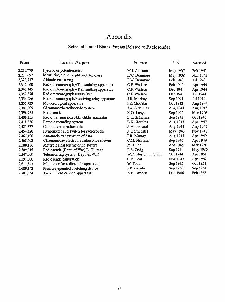
Appendix
Selected United States Patents Related to Radiosondes
Patent Invention/Purpose
2,230,779 Pyrometer potentiometer 2,277,692 Measuring cloud height and thickness 2,323,317 Altitude measuring 2,347,160 Radiometeorography/Transmitting apparatus 2,347,345 Radiometeorography/Transmitting apparatus 2,352,578 Radiometeorograph transmitter 2,354,086 Radiometeorograph/Receiving relay apparatus 2,355,739 Meteorological apparatus 2,381,009 Chronometric radiosonde system 2,396,955 Radiosonde 2,409,155 Radio transmission N.E. Gibbs apparatus 2,418,836 Remote recording system 2,425,537 Calibration of radiosonde 2,454,320 Hygrometer and switch for radiosondes 2,467,400 Automatic transmission of data 2,468,703 Chronometric electronic radiosonde system 2,500,186 Meterological telemetering system 2,509,215 Radiosonde (Dept. of War) L. Hillman 2,547,009 Telemetering system (Dept. of War) 2,591,600 Radiosonde calibration 2,613,347 Modulator for radiosonde apparatus 2,689,342 Pressure operated switching device 2,701,354 Airborne radiosonde apparatus
Patentee Filed Awarded
M.J. Johnson May 1937 Feb 1941 F.W Dunmore May 1938 Mar 1942 F.W Dunmore Feb 1940 Jul 1943 C.F.Wallace Feb 1940 Apr 1944 C.F.Wallace Dec 1941 Apr 1944 C.F.Wallace Dec 1941 Jun 1944 J.R. Mackay Sep 1941 Jul 1944 I.E. McCabe Oct 1942 Aug 1944 J.A. Siderman Aug 1944 Aug 1945 K.O. Lange Sep 1942 Mar 1946 E.L. Schellens Sep 1942 Oct 1946 B.K. Hawkes Aug 1943 Apr 1947 J. Hornbostel Aug 1943 Aug 1947 J. Hornbostel May 1943 Nov 1948 PR. Murray Aug 1945 Apr 1949 CM. Hammel Sep 1946 Apr 1949 M.Kline Apr 1945 Mar 1950 L.S.Craig Sep 1944 May 1950 W.D. Huston, J. Grady Oct 1944 Apr 1951 C.B. Pear Nov 1948 Apr 1952 W. Todd Sep 1945 Oct 1952 PR. Goudy Sep 1950 Sep 1954 A.E.Bennett Dec 1946 Feb 1955
75
Literature Cited
Abbot, C, F. Fowle, and L. Aldrich 1915. New Evidence on the Intensity of Solar Radiation Outside the At
mosphere. Smithsonian Miscellaneous Collections, 45:1-55. Anonymous
1928. The Radio Industry. New York: A. W. Shaw and Co. 1961. Handbook of Meteorological Instruments, Part II. 551 pages. Lon
don: Her Majesty's Stationary Office. Armstrong, E.H.
1917. Some Recent Developments in Regenerative Circuits. Proceedings of the Institute of Radio Engineers, 10(8):244.
Beelitz, P. 1954. Radiosonden. 136 pages. Berlin: VEB-Verlag.
Benade, J., and R. Doan 1935. Apparatus for Transmitting Cosmic Ray Data from the Stratosphere.
Physical Review, 47:198. Blair, W.
1937. Some Relationships between Radio and Meteorology. Transcription of lecture of 7 April at New York University (in the Blair Papers, currently in the custody of W. Blair, Jr., of Monmouth Beach, New Jersey).
Blair, W., and H. Lewis 1931. Radio Tracking of Meteorological Balloons. Proceedings of the In
stitute of Radio Engineers, 19:1531 -1560. Blake, G.
1928. History of Radio Telegraphy and Telephony. 403 pages. London: Chapman & Hall Ltd.
Borden, P., and N. Mayo-Wells 1959. Telemetering Systems. 341 pages. New York: Reinhold Publishing.
Borden, P., and G. Thynell 1948. Principles and Methods of Telemetering. 231 pages. New York: Re
inhold Publishing Corp. Brasefield, C.
1948. Measurement of Air Temperature in the Presence of Solar Radiation. Journal of Meteorology, 5:147-151.
Bureau, R. 1929. Sondages de pression et de temperature par radiotelegraphie.
Comptes Rendus, 188:1565-1566. 1931. Sondages par ballons munis d'un emetteur radioelectrique. La
Meteorologie, 7:304-320. Carmichael, H., and E. Dymond
1939. High Altitude Cosmic Radiation Measurements near the North Geomagnetic Pole. Proceedings of the Royal Society, London, A171: 321-344.
Chaffee, E.L. 1933. Theory of Thermionic Vacuum Tubes. 652 pages. New York:
McGraw-Hill. Churchill, W.S.
1948. 77;<? Gathering Storm. 784 pages. Boston: Houghton-Mifflin. Coblentz, W., and R. Stair
1939. Distribution of Ozone in the Atmosphere. Journal of Research, National Bureau of Standards, 22:573-606.
Craft, E., and E. Colpitts 1919. Radiotelephony. Transactions of the Institute of Electrical Engi
neers, 38:305-343. Curtis, L.F., and A. Astin
1935. A Practical System for Radio-Meteorography. Journal of the Aeronautical Sciences, 3:35-39.
1936. An Electric Motor for Radio Meteorgraphs. Review of Scientific Instruments, 7:358-359.
de Fonvielle, W. 1899. Les ballons-sondes de mm. Hermite et Besancon et les ascensions
Internationales, precede d'une introduction par m. Bouquet de la Grye. 112 pages. Paris: Gauthier-Villars et fils.
de Forest, L. 1906. The Audion: A New Receiver for Wireless Telegraphy. Transactions
of the American Institute of Electrical Engineering, 25:735-763. de la Baume-Pluvinel, A.
1903. L'analyse spectral automatique. L'Aerophile, 2:159-162. Diamond, H., W. Hinman, and F. Dunmore
1937. Development of a Radio Meteorgraph System for the Navy Department. Bulletin of the American Meteorological Society, 18:73-99.
1938. A Method for the Investigation of Upper-Air Phenomena and Its Application to Radio Meteorography. Journal of Research, National Bureau of Standards, 20:369-392.
Diamond, H., W. Hinman, F. Dunmore, and E. Lapham 1940. An Improved Radiosonde and Its Performance. Journal of Research,
National Bureau of Standards, 25:327-367. Dines, W.
1906. Two New Light Meteorographs for Use with Unmanned Balloons. Symon 's Meteorological Magazine, 41:101.
Duckert, P. 1932. Die Entwicklung der Telemeteorgraphie und ihrer Instrumentanien.
Beitrdge zur Physik der Freien Atmosphare, 18:68-80. 1933. Das Radiosondenmodell Telefunken und seine Anwendung. Bei
trdge zur Physik der Freien Atmosphare, 20:303-311. 1935. Telemeteorometrie. In E. Kleinschmidt, editor, Handbuch der Mete-
orologischen Instrumente, pages 573-584. Berlin: Springer. Dymond, E.
1947. The Kew Radiosonde. Proceedings of the Royal Society, London, 59:645-666.
Eddy. 1898. Kite Meteorgraph. U.S. Monthly Weather Review, 26:451^53.
Espenscheid, L. 1922. The Origin and Development of Radio Telephony. Proceedings of
the Institute of Radio Engineers, 10:3-10. Fleming, R.
1919. The Thermionic Valve and Its Development in Radiography and Telegraphy. London: The Wireless Press.
Friedman, R. 1982. Constituting the Polar Front, 1919-1920. Isis, 74:343-362.
Garratt, G.R.M. 1965. The Early History of Telegraphy. Phillip's Technical Review.
26:265-284. 1994. The Early History of Radio: From Faraday to Marconi. History of
Technology Series, 20: 93 pages. Gillespie, C.
1983. The Montgolfier Brothers and the Invention of Aviation. 211 pages. Princeton, New Jersey: Princeton University Press.
Goldsmith, A.E. 1918. Radio Telephony. 247 pages. New York: The Wireless Press, Inc.
Hauer, A., and M. van Tol 1954. A Radiosonde for Meteorological Observations. Phillips Technical
Reviews, 16:148-154. Heck, L., and G. Sudeck
1931. Neue Meteorgraphen fur drahtlose Fernvebertragung. Gerlands zur Beitrdge Geophysik, 31:291 -314.
Hergesell, H.
1897. Die Entwicklung eines barothermographen. Meteorologischen
76
NUMBER 53 77
Zeitschrift, 14:121-122. 1904. Ballon-Aufsteige iiber dem freien Meer zur Erfassung der Tempera-
tur. Beitrdge zur Physik der Freien Atmosphare, 1:200-204. 1932. Preface. In P. Duckert and B. Thieme, Neue radiometeorographische
Methoden, Beitrdge zur Physik der Freien Atmosphare, 18:50-67. Hermite, G.
1893. L'exploration de la haute atmosphere experience du 21 Mars 1893. Comptes Rendus, 116:766-768.
Hertz, H. 1888. Electromagnetic Waves in the Air and Their Reflection. Pages
609-623. Leipzig: Johann Ambrosius Barth. Hinzpeter, H.
1951. A New Radiosonde. Annalen Meteorologischen, Hamburg, 4:393-401.
Howeth, L.S. 1963. History of Communications Electronics in the United States Navy.
657 pages. Washington, D.C.: U.S. Government Printing Office. Hughes, D.E.
1878. Paper on Microphones. Proceedings of the Royal Society, London, 27:362.
Idrac, P., and R. Bureau 1927. Experiences sur la propagation des sondes radiotelegraphiques en
altitude. Comptes Rendus, 184:691-692. Isono, K., and Y. Huziwara
1950. Improved Code Sending Type Radiosonde. Papers on Meteorology and Geophysics, 1:299-305.
J.F.H. 1932. The Modem Meteorograph. Nature, 130:1006-1007.
Johnson, T. 1937. Radio Transmission of Coincidence Counter Cosmic Ray Measure
ments in the Stratosphere. Journal of the Franklin Institute, 223: 339-354.
Kelvin, Lord (See Sir William Thomson) Kleinschmidt, E., editor
1935. Handbuch der Meteorologischen Instrumente und Ihrer Auswer-tung. 733 pages. Berlin J. Springer.
Kuiper, G. 1946. German Astronomy during the War. Popular Astronomy, 54:263-
287. Lange, K.O.
1935. Other Radio Meteorographs. Bulletin of the American Meteorological Society, 16:233-236, 267-271, 297-300.
1936. The 1935 Radio Meteorgraphs of Blue Hill Observatory. Bulletin of the American Meteorological Society, 17:136-147.
1937. The 1936 Radio Meteorgraphs of Blue Hill Observatory. Bulletin of the American Meteorological Society, 18:107-126.
Lodge, O.J. 1908. Signalling across Space without Wires. 133 pages. London: The
Electrician Printing and Publishing. Lugeon, J., P. Ackerman, and M. Bohanenbush
1948. La radiosonde Suisse. In Annalen der Schweizerischen Meteorologischen Anstalt. 386 pages. Zurich: Druck A.G.
Maier, O., and L. Wood 1937. The GALCIT Radio Meteorgraph. Journal of the Aeronautical Sci
ences, 4:417-422. Maxwell, J.C.
1865. A Dynamical Theory of the Electromagnetic Field. Philosophical Transactions of the Royal Society of London, 155:459-512.
Meissner, A. 1922. The Development of Tube Transmitters by the Telefunken Com
pany. Proceedings of the Institute of Radio Engineers, 10:3-10. Middleton, W.E.K.
1969a. Invention of the Meteorological Instruments. 362 pages. Baltimore:
Johns Hopkins University Press. 1969b. Catalog of Meteorological Instruments in the Museum of History
and Technology. 128 pages. Washington, D.C.: Smithsonian Institution Press.
Middleton, W.E.K., and A. Spilhaus 1953. Meteorological Instruments. Third revised edition, 286 pages. Tor
onto, Canada: University of Toronto Press. Millikan, R.
1950. Autobiography. 311 pages. New York: Prentice-Hall. Millikan, R., and I. Bowen
1926. High Frequency Rays of Cosmic Origin. Physical Review, 27: 353-361.
Moltchanoff, P. 1928. Zur Technik der Erforschung der Atmosphare. Beitrdge zur Physik
der Freien A tmosphdre, 14:39-48. 1931. Methode der radiosonde. Garlands zur Beitrdge Geophysik,
34:35-36. 1933. Drei Jahre Aufsteige von Radiosonden im Institute der Aerologie,
Sloutzk, U.S.S.R. Meteorologische Zeitschrift, 50:428. Morecroft, J.
1921. Principles of Radio Communication. 935 pages. New York: John Wiley & Sons.
O'Brien, B. 1939. Refinements in Atmospheric Transmission Measurement for Solar
Constant Determination. Physical Review, 55:1142. O'Brien, B., L. Steadman, and H. Stewart
1937. Measurement of Solar Radiation from High Altitude Sounding Balloons. Science, 86:445.
Pfotzer, G. 1972. History of the Use of Balloons in Scientific Measurements. Space
Science Review, 13:199-242. Ranger, R.
1926. Transmission and Reception of Photo Diagrams. Proceedings of the Institute of Radio Engineers, 14:1-16.
Regener, E. 1932. Messung der Ultrastrahlung in der Stratosphare. Naturwissen-
schaften, 20:695-699. 1935. Erfahrungen und Ergebnisse mit Registrierballonen und Registrier-
apparaten in der Stratosphare. Beitrdge zur Physik der Frien Atmosphare, 22:249-260.
Regener, E., and V. Regener 1934. Aufnahme des Ultravioletten Sonnenspektrums in der Stratosphare
und vertikale Ozonverteilung. Physikalische Zeitung, 35:788-793. Rothe, E.
1920. Un nouveau meteorgraph. Comptes Rendus. 170:1197-1198. Shaw, Sir N.
1926. Manual of Meteorology. Volume 1, 341 pages. Cambridge: Cambridge University Press.
1942. Meteorology in History. 343 pages. Cambridge: Cambridge University Press.
Sittel, K., and E. Menzer 1950. An Improved Fully Electric Radiosonde. Bulletin of the American
Meteorological Society, 31:341-349. Snyder, W.F., and C. Bragaw
1986. Achievement in Radio. 863 pages. Washington, D.C.: U.S. Government Pringting Office.
Stair, R., and W. Coblentz 1938. Radiometric Measurements of Ultraviolet Solar Intensities in the
Stratosphere. Journal of Research, National Bureau of Standards, 20:185-215.
Sterling, G. 1928. The Radio Manual for Radio Engineers, Inspectors, Students, Oper
ators and Radio Fans. 666 pages. New York: D. Van Nostrand Co. Stringer, E.
1972. Foundations of Climatology. 568 pages. San Fransisco: H. Freeman
&Co.
78 SMITHSONIAN STUDIES IN HISTORY AND TECHNOLOGY
Teisserenc de Bort, L.P. 1899. Sur la temperature et ses variations dans I'atmosphere libre, d'apres
les observations de quatre-vignt-dix ballons-sondes. Comptes Rendus, 129:417—420.
Thomas, H. 1938. The Determination of Meteorological Conditions by the Use of Ra-
diosounding Balloons. Proceedings of the Royal Society, London, Al 67:227-250.
Thomson, Sir William (Lord Kelvin) 1853. On Transient Electric Currents. Philosophy Magazine, 5:393-398.
Tissandier, G. 1896. Sur un system meteorgraphique universal. La Nature, 24:145-146.
Tyne, G. 1977. Saga of the Vacuum Tube. 494 pages. Indianapolis, Indiana:
Howard W. Sams & Co. Vaisala, V.
1932. Bestrebungen und Vorschlaege zur Entwicklung der radio meteorg-raphischen methoden. Societas Scientiarium Fennica, 6:6-10.
1935. Eine Naue Radiosonde. Mitteilungen des Meteorologischen Institutes der Universitaet Helsingfors, 29:1012-1029.
Vernov, S. 1934. On the Study of Cosmic Rays at Great Altitudes. Physical Review,
46:822-823.
1935. Radio-Transmission of Cosmic Ray Data from the Stratosphere. Nature, 135:1072-1073.
Weagaut, R.A., and F.N. Waterman 1918. Directive Wireless. British Patent No. 129625.
Weickmann, L. 1938. Denkschrift Uber Radiosonden-Konstruktionen. 682 pages. Berlin:
Springer-Verlag. Wenstrom, W.
1932. Historical Review of Ultra-Short-Wave Progress. Proceedings of the
Institute of Radio Engineers, 20(1):95-112. 1934. Radiometeorography as Applied to Unmanned Balloons. Monthly
Weather Review, 62:121-126.


REQUIREMENTS FOR SMITHSONIAN SERIES PUBLICATION
Manuscripts intended for series publication receive substantive review (conducted by their originating Smithsonian museums or offices) and are submitted to the Smithsonian Institution Press with Form SI-36, which must show the approval of the appropriate authority designated by the sponsoring organizational unit. Requests for special treatment—use of color, foldouts, case-bound covers, etc.—require, on the same form, the added approval of the sponsoring authority.
Review of manuscripts and art by the Press for requirements of series format and style, completeness and clarity of copy, and arrangement of all material, as outlined below, will govern, within the judgment of the Press, acceptance or rejection of manuscripts and art.
Copy must be prepared on typewriter or word processor, double-spaced, on one side of standard white bond paper (not erasable), with 1 W margins, submitted as ribbon copy (not carbon or xerox), in loose sheets (not stapled or bound), and accompanied by original art. Minimum acceptable length is 30 pages.
Front matter (preceding the text) should include: title page with only title and author and no other information; abstract page with author, title, series, etc., following the established format; table of contents with indents reflecting the hierarchy of heads in the paper; also, foreword and/or preface, if appropriate.
First page of text should carry the title and author at the top of the page; second page should have only the author's name and professional mailing address, to be used as an unnumbered footnote on the first page of printed text.
Center heads of whatever level should be typed with initial caps of major words, with extra space above and below the head, but no other preparation (such as all caps or underline, except for the underline necessary for generic and specific epithets). Run-in paragraph heads should use period/dashes or colons as necessary.
Tabulations within text (lists of data, often in parallel columns) can be typed on the text page where they occur, but they should not contain rules or numbered table captions.
Formal tables (numbered, with captions, boxheads, stubs, rules) should be submitted as carefully typed, double-spaced copy separate from the text; they will be typeset unless otherwise requested. If camera-copy use is anticipated, do not draw rules on manuscript copy.
Taxonomic keys in natural history papers should use the aligned-couplet form for zoology and may use the multi-level indent form for botany. If cross referencing is required between key and text, do not include page references within the key, but number the keyed-out taxa, using the same numbers with their corresponding heads in the text.
Synonymy in zoology must use the short form (taxon, author, yearpage), with full reference at the end of the paper under "Literature Cited." For botany, the long form (taxon, author, abbreviated journal or book title, volume, page, year, with no reference in "Literature Cited") is optional.
Text-reference system (author, year:page used within the text, with full citation in "Literature Cited" at the end of the text) must be used in place of bibliographic footnotes in all Contributions Series and is strongly recommended in the Studies Series: "(Jones, 1910:122)" or "...Jones (1910:122)." If bibliographic footnotes are
required, use the short form (author, brief title, page) with the full citation in the bibliography.
Footnotes, when few in number, whether annotative or bibliographic, should be typed on separate sheets and inserted immediately after the text pages on which the references occur. Extensive notes must be gathered together and placed at the end of the text in a notes section.
Bibliography, depending upon use, is termed "Literature Cited," "References," or "Bibliography." Spell out titles of books, articles, journals, and monographic series. For book and article titles use sentence-style capitalization according to the rules of the language employed (exception: capitalize all major words in English). For journal and series titles, capitalize the initial word and all subsequent words except articles, conjunctions, and prepositions. Transliterate languages that use a non-Roman alphabet according to the Library of Congress system. Underline (for italics) titles of journals and series and titles of books that are not part of a series. Use the parentheses/colon system for volume (number):pagination: "10(2):5-9." For alignment and arrangement of elements, follow the format of recent publications in the series for which the manuscript is intended. Guidelines for preparing bibliography may be secured from Series Section, SI Press.
Legends for illustrations must be submitted at the end of the manuscript, with as many legends typed, double-spaced, to a page as convenient.
Illustrations must be submitted as original art (not copies) accompanying, but separate from, the manuscript. Guidelines for preparing art may be secured from the Series Section, SI Press. All types of illustrations (photographs, line drawings, maps, etc.) may be intermixed throughout the printed text. They should be termed Figures and should be numbered consecutively as they will appear in the monograph. If several illustrations are treated as components of a single composite figure, they should be designated by lowercase italic letters on the illustration; also, in the legend and in text references the italic letters (underlined in copy) should be used: "Figure 9b." Illustrations that are intended to follow the printed text may be termed Plates, and any components should be similarly lettered and referenced: "Plate 9b." Keys to any symbols within an illustation should appear on the art rather than in the legend.
Some points of style: Do not use periods after such abbreviations as "mm, ft, USNM, NNE." Spell out numbers "one" through "nine" in expository text, but use digits in all other cases if possible. Use of the metric system of measurement is preferable; where use of the English system is unavoidable, supply metric equivalents in parentheses. Use the decimal system for precise measurements and relationships, common fractions for approximations. Use day/month/ year sequence for dates: "9 April 1976." For months in tabular listings or data sections, use three-letter abbreviations with no periods: "Jan, Mar, Jun," etc. Omit space between initials of a personal name: "J.B. Jones."
Arrange and paginate sequentially every sheet of manuscript in the following order: (1) title page, (2) abstract, (3) contents, (4) foreword and/or preface, (5) text, (6) appendices, (7) notes section, (8) glossary, (9) bibliography, (10) legends, (11) tables. Index copy may be submitted at page proof stage, but plans for an index should be indicated when the manuscript is submitted.

Related Documents