The Interstate Natural Gas Transmission System: Scale, Physical Complexity and Business Model Executive Summary The natural gas pipeline network in the U.S. consists of gathering pipelines, interstate natural gas transmission pipelines, intrastate natural gas transmission pipelines, natural gas distribution pipelines, and associated compressor and metering stations, along with storage facilities and controls systems. Taken together, the natural gas transportation network moves nearly one quarter of the U.S. energy demand, according to the U.S. Energy Information Administration. Natural gas transmission systems have numerous interconnection points and market hubs. The interconnected nature of the natural gas transmission network facilitates the competitive market place and supply reliability. The network is highly regulated by federal entities including the Federal Energy Regulatory Commission (FERC), Pipeline and Hazardous Materials Safety Administration (PHMSA), Occupational Safety and Health Administration (OSHA), Transportation Safety Administration (TSA), and Environmental Protection Agency (EPA). From an economic standpoint, intrastate natural gas transmission pipeline systems and local distribution pipelines are regulated by state public service and public utility commissions. Many local authorities are involved with regulating land use for all forms of pipelines. Natural gas, as it is produced from the reservoir contains various hydrocarbon liquids and water which would interfere with the operation of natural gas compressors and other equipment. Consequently, safely managing these liquids is of major concern to interstate natural gas transmission, and other pipelines. Most of the hydrocarbon liquids and water are removed in dehydration and processing plants, either before or shortly after the natural gas stream enters interstate natural gas transmission pipelines. Those liquids which remain condense from the stream as it moves along. Various pieces of equipment are installed along the pipeline and at stations to manage the remaining liquids which might condense from the stream in the course of normal operations. Small amounts of lubricating oils enter the natural gas stream at compressor stations and are managed with the same types of equipment used to manage hydrocarbon liquids. Given that natural gas interstate transmission systems operate at pressures on the order of 500 to 1,800 psi they are closed and closely contained. Pipelines and stations undergo extensive maintenance and accordingly have long lives. Given the dedication to routine and robust maintenance, it is not unusual for pipelines and equipment installed 50 or more years ago to still be in operation. The U.S inter and intra state natural gas transmission network is the envy of many less developed countries. Even the European Common Union is working to move the European natural gas transmission network towards the U.S. competitive and interconnected model to facilitate commerce, safety, and reliability.

Welcome message from author
This document is posted to help you gain knowledge. Please leave a comment to let me know what you think about it! Share it to your friends and learn new things together.
Transcript
The Interstate Natural Gas Transmission System: Scale, Physical Complexity and Business Model
Executive Summary
The natural gas pipeline network in the U.S. consists of gathering pipelines, interstate natural gas transmission pipelines, intrastate natural gas transmission pipelines, natural gas distribution pipelines, and associated compressor and metering stations, along with storage facilities and controls systems. Taken together, the natural gas transportation network moves nearly one quarter of the U.S. energy demand, according to the U.S. Energy Information Administration. Natural gas transmission systems have numerous interconnection points and market hubs. The interconnected nature of the natural gas transmission network facilitates the competitive market place and supply reliability.
The network is highly regulated by federal entities including the Federal Energy Regulatory Commission (FERC), Pipeline and Hazardous Materials Safety Administration (PHMSA), Occupational Safety and Health Administration (OSHA), Transportation Safety Administration (TSA), and Environmental Protection Agency (EPA). From an economic standpoint, intrastate natural gas transmission pipeline systems and local distribution pipelines are regulated by state public service and public utility commissions. Many local authorities are involved with regulating land use for all forms of pipelines.
Natural gas, as it is produced from the reservoir contains various hydrocarbon liquids and water which would interfere with the operation of natural gas compressors and other equipment. Consequently, safely managing these liquids is of major concern to interstate natural gas transmission, and other pipelines. Most of the hydrocarbon liquids and water are removed in dehydration and processing plants, either before or shortly after the natural gas stream enters interstate natural gas transmission pipelines. Those liquids which remain condense from the stream as it moves along. Various pieces of equipment are installed along the pipeline and at stations to manage the remaining liquids which might condense from the stream in the course of normal operations. Small amounts of lubricating oils enter the natural gas stream at compressor stations and are managed with the same types of equipment used to manage hydrocarbon liquids.
Given that natural gas interstate transmission systems operate at pressures on the order of 500 to 1,800 psi they are closed and closely contained. Pipelines and stations undergo extensive maintenance and accordingly have long lives. Given the dedication to routine and robust maintenance, it is not unusual for pipelines and equipment installed 50 or more years ago to still be in operation.
The U.S inter and intra state natural gas transmission network is the envy of many less developed countries. Even the European Common Union is working to move the European natural gas transmission network towards the U.S. competitive and interconnected model to facilitate commerce, safety, and reliability.

Introduction The U. S. depends on natural gas for almost one quarter of its energy needs. Natural gas
consumers, including residential, commercial, industrial and power generation facilities expect the reliable 24/7/365 supply of natural gas.
The natural gas pipeline network in the U.S. consists of gathering pipelines, interstate natural gas transmission pipelines, intrastate natural gas transmission pipelines, natural gas distribution pipelines and associated compressor and metering stations along with storage facilities and controls. The network is highly regulated by federal entities including the Federal Energy Regulatory Commission (FERC), Pipeline and Hazardous Materials Safety Administration (PHMSA), Occupational Safety and Health Administration (OSHA), Transportation Safety Administration (TSA), and Environmental Protection Agency (EPA). From an economic standpoint, intrastate natural gas transmission pipeline systems and local distribution pipelines are regulated by state public service and public utility commissions. Many local authorities are involved with regulating land use for all forms of pipelines.
Long-range natural gas transmission pipelines and other facilities such as compressor and meter stations were first built in the U. S. starting around the late 1920’s. Following World War II, construction of long distance natural gas transmission lines accelerated; in fact, almost half (142,000 miles) of the natural gas pipelines currently in service were constructed in the 1950’s and 1960’s.1
As the nation grew, the interstate natural gas transmission business model evolved to meet the economic reality of the day. FERC regulations resulted in a change from providing gas merchant services to providing gas transportation services, which drove interstate natural gas transmission to interconnect with each other and with other pipelines for commercial reasons (Figure 1).
Figure 1. The U. S. natural gas pipeline network. Source: Energy Information Agency.
Today, there are no major interstate pipelines that operate in isolation, i.e., without interconnection with at least one or more other pipelines. Typically, there are interconnects (receipt and/or delivery) with many other pipelines and multiple customers on all interstate pipelines.
Interstate and intrastate natural gas transmission pipelines are generally not well known to the general public, being mostly buried with only above ground markers to show their location; they are “out of sight and out of mind”. Where above ground structures such as compressor, meter, pigging, and valve stations exist, they are secured against public access.
The purposes of this paper are:
• describe and define the equipment used in interstate natural gas transmission systems;
• provide a sense of the scope of complexity of these systems and components; and
1Extracted August 6, 2010 from
http://www.eia.doe.gov/energyexplained/index.cfm?page=natural_gas_pipelines
2

• describe the liquids removal process inherent to these systems as well as those installed to capture and prevent the migration of PCB-containing lubricants.
Natural Gas Pipeline quality natural gas is an odorless transparent gas, consisting primarily of
methane (CH4), with minor amounts of ethane, propane, butane, hydrogen sulfide, carbon dioxide, nitrogen, and oxygen. The first step downstream of production areas in the natural gas transmission process is separating the various liquids and gases from each other. The liquids are separated from the gases and from each other, with water going into one tank, crude oil into another tank, and the gas stream going directing into a pipeline after processing and/or dehydration.
In Figure 2 the separators are in the right background and the storage tanks in the foreground contain crude oil and produced water. Barely visible to the right of the tanks is a small gray box containing gas metering equipment.
Figure 2. Lease separators and oil tanks. Courtesy Pipeline Knowledge & Development.
The most economical and efficient way to transport natural gas is via pipeline under pressure.2 In order to transport natural gas economically and efficiently, it is compressed and flows through a continuous pipeline under pressure. While the “dry” natural gas stream moves through the buried pipeline, it contains some minor amounts of condensable light-end hydrocarbons and water. As this stream cools, some of the hydrocarbons and water reach their dew points and condense into liquids.
While liquids have always been removed for from natural gas streams for operating reasons, economic incentive exists to remove them as well as hydrocarbon liquids are normally priced higher than methane on an energy equivalent bases. For gas to be transported on the interstate natural gas transmission system it must meet “pipeline quality natural gas” standards. Typical pipeline quality gas specification is a moisture content of 7 lbs of water or less per 1 MMSCF.
The Natural Gas Pipeline Network The U.S. Energy Information Administration (EIA) describes the U.S. natural gas
network as a highly integrated transmission and distribution grid that can transport natural gas to and from nearly any location in the lower 48 States. The natural gas pipeline grid comprises:
• More than 210 natural gas pipeline systems. • 305,000 miles of interstate and intrastate transmission pipelines. • More than 1,400 compressor stations that maintain pressure on the natural gas pipeline
network and assure continuous forward movement of supplies. • More than 11,000 delivery points, 5,000 receipt points, and 1,400 interconnection points
that provide for the transfer of natural gas throughout the United States. • 24 hubs or market centers that provide additional interconnections.
2 Vehicular/rail transport of compressed natural gas is not economically feasible because it is
significantly less dense than a liquid (e.g., oil) or a solid (e.g., coal). 3

• 400 underground natural gas storage facilities. • 49 locations where natural gas can be imported/exported via pipelines. • 8 LNG (liquefied natural gas) import facilities and 100 LNG peaking facilities3.
The interconnected nature of this network is one of the keys to the system’s reliability. The European Common Union, for example, through Directive 2003/55/EC is currently attempting to open up competition and which will help drive the European network towards the interconnected and competitive nature of the U.S. natural gas network.
Natural Gas Pipeline Functions Natural gas pipelines provide three transportation functions, gathering, transmission
(interstate and intrastate), and distribution. Pipeline companies, along with storage companies store natural gas in geologic formations and other storage facilities to balance production supply and market demand. They receive gas from natural gas producing companies and move it to downstream customers. Some, but not all, natural gas requires processing to meet gas quality specifications. Gas processing may include dehydration plants, amine units for removal of hydrogen sulfide and/or carbon dioxide, and liquid extraction plants where the majority of the liquids are removed from the gas stream. Liquids extraction plants are typically located near the production areas (Figure 3).
Figure 3. Gas liquids extraction plant. Courtesy Pipeline Knowledge & Development.
Liquid extraction plants are not part of the transportation system nor are their rates, or their returns, regulated. Dehydration plant, however, depending on gas quality, may be installed and owned and operated by the interstate natural gas transmission company. These plants remove liquids, particularly water, from the gas stream.
In Figure 4 the series of horizontal pipes in the background is the “slug catcher” to collect and separate liquids from the three phase flow (i.e., gas, condensate, and water) arriving from production areas. The two towers in the right foreground are glycol dehydration towers that remove water vapor from the gas prior to compression and transmission. The two aluminum horizontal objects in the center foreground are glycol re-boilers that heat the glycol to boil off the absorbed water and allow the glycol to be re-used.
Figure 4. Dehydration plant.
Interstate and intrastate natural gas transmission pipelines sometimes called “main lines” transport the gas from production areas or gas plants to downstream customers, including distribution companies, and industrial and other end users. Distribution lines receive gas from interstate and intrastate natural gas transmission companies and deliver the gas to homes, schools, hospitals, plants and commercial establishments (Figure 5).
3 Extracted August 6, 2010 from
http://www.eia.doe.gov/pub/oil_gas/natural_gas/analysis_publications/ngpipeline/index.html
4
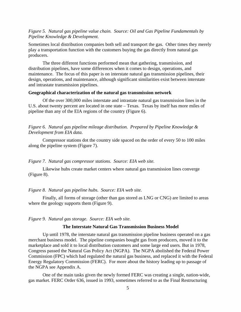
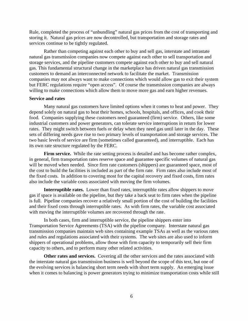
Figure 5. Natural gas pipeline value chain. Source: Oil and Gas Pipeline Fundamentals by Pipeline Knowledge & Development.
Sometimes local distribution companies both sell and transport the gas. Other times they merely play a transportation function with the customers buying the gas directly from natural gas producers.
The three different functions performed mean that gathering, transmission, and distribution pipelines, have some differences when it comes to design, operations, and maintenance. The focus of this paper is on interstate natural gas transmission pipelines, their design, operations, and maintenance, although significant similarities exist between interstate and intrastate transmission pipelines.
Geographical characterization of the natural gas transmission network Of the over 300,000 miles interstate and intrastate natural gas transmission lines in the
U.S. about twenty percent are located in one state – Texas. Texas by itself has more miles of pipeline than any of the EIA regions of the country (Figure 6).
Figure 6. Natural gas pipeline mileage distribution. Prepared by Pipeline Knowledge & Development from EIA data.
Compressor stations dot the country side spaced on the order of every 50 to 100 miles along the pipeline system (Figure 7).
Figure 7. Natural gas compressor stations. Source: EIA web site.
Likewise hubs create market centers where natural gas transmission lines converge (Figure 8).
Figure 8. Natural gas pipeline hubs. Source: EIA web site.
Finally, all forms of storage (other than gas stored as LNG or CNG) are limited to areas where the geology supports them (Figure 9).
Figure 9. Natural gas storage. Source: EIA web site.
The Interstate Natural Gas Transmission Business Model Up until 1978, the interstate natural gas transmission pipeline business operated on a gas
merchant business model. The pipeline companies bought gas from producers, moved it to the marketplace and sold it to local distribution customers and some large end users. But in 1978, Congress passed the Natural Gas Policy Act (NGPA). The NGPA abolished the Federal Power Commission (FPC) which had regulated the natural gas business, and replaced it with the Federal Energy Regulatory Commission (FERC). For more about the history leading up to passage of the NGPA see Appendix A.
One of the main tasks given the newly formed FERC was creating a single, nation-wide, gas market. FERC Order 636, issued in 1993, sometimes referred to as the Final Restructuring
5
Rule, completed the process of “unbundling” natural gas prices from the cost of transporting and storing it. Natural gas prices are now decontrolled, but transportation and storage rates and services continue to be tightly regulated.
Rather than competing against each other to buy and sell gas, interstate and intrastate natural gas transmission companies now compete against each other to sell transportation and storage services, and the pipeline customers compete against each other to buy and sell natural gas. This fundamental structural change in the marketplace has driven natural gas transmission customers to demand an interconnected network to facilitate the market. Transmission companies may not always want to make connections which would allow gas to exit their system but FERC regulations require “open access”. Of course the transmission companies are always willing to make connections which allow them to move more gas and earn higher revenues.
Service and rates Many natural gas customers have limited options when it comes to heat and power. They
depend solely on natural gas to heat their homes, schools, hospitals, and offices, and cook their food. Companies supplying these customers need guaranteed (firm) service. Others, like some industrial customers and power generators, can tolerate service interruptions in return for lower rates. They might switch between fuels or delay when they need gas until later in the day. These sets of differing needs gave rise to two primary levels of transportation and storage services. The two basic levels of service are firm (sometimes called guaranteed), and interruptible. Each has its own rate structure regulated by the FERC.
Firm service. While the rate setting process is detailed and has become rather complex, in general, firm transportation rates reserve space and guarantee specific volumes of natural gas will be moved when needed. Since firm rate customers (shippers) are guaranteed space, most of the cost to build the facilities is included as part of the firm rate. Firm rates also include most of the fixed costs. In addition to covering most for the capital recovery and fixed costs, firm rates also include the variable costs associated with moving the firm volumes.
Interruptible rates. Lower than fixed rates, interruptible rates allow shippers to move gas if space is available on the pipeline, but they take a back seat to firm rates when the pipeline is full. Pipeline companies recover a relatively small portion of the cost of building the facilities and their fixed costs through interruptible rates. As with firm rates, the variable cost associated with moving the interruptible volumes are recovered through the rate.
In both cases, firm and interruptible service, the pipeline shippers enter into Transportation Service Agreements (TSA) with the pipeline company. Interstate natural gas transmission companies maintain web sites containing example TSAs as well as the various rates and rules and regulations associated with their systems. The web sites are also used to inform shippers of operational problems, allow those with firm capacity to temporarily sell their firm capacity to others, and to perform many other related activities.
Other rates and services. Covering all the other services and the rates associated with the interstate natural gas transmission business is well beyond the scope of this text, but one of the evolving services is balancing short term needs with short term supply. An emerging issue when it comes to balancing is power generators trying to minimize transportation costs while still
6
having quick access to relatively large amounts of gas as when the electric grid requires additional power.4
Tariffs. Interstate natural gas transmission companies publish “tariffs” which contain the rates charged along with the rules and regulations associated with moving gas on their systems. The entire interstate pipeline network is interconnected, so the rules and regulations as well as quality requirements of interstate natural gas transmission companies must harmonize across receipt and delivery points throughout the grid. To that end, interstate natural gas transmission companies participate in organizations such as the North American Energy Standards Board (NAESB) which serves as an industry forum for the development and promotion of standards leading to a seamless marketplace for wholesale and retail natural gas and electricity.5
An interconnect is by definition a connection point between the transmission company and the receiving party, which may be another pipeline (interstate or intrastate), distribution company, or other customer. Each company typically owns and is responsible for operation of their assets at the interconnect location and publishes their own tariff for that interconnect.
Properties of the Natural Gas Stream As gases are compressed, the temperature and pressure both increase within normal
ranges. The relationship between temperature, pressure, and state (liquid or gas) is described by phase diagrams which graphically show the combinations of pressure and temperature where the substance is a gas, liquid, or can exist as both. Phase diagrams are used to predict the behavior of the particular gas.
Phase diagram The phase diagram for a particular type of molecule, methane for example, shows the
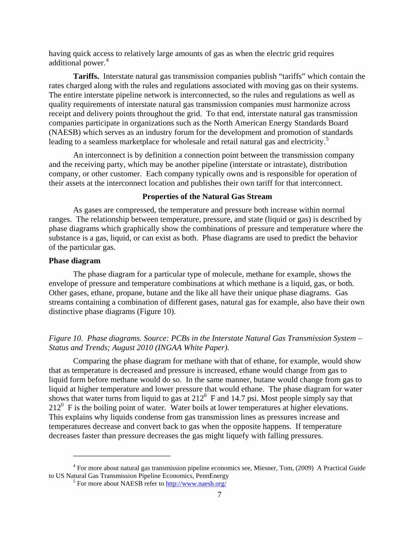
envelope of pressure and temperature combinations at which methane is a liquid, gas, or both. Other gases, ethane, propane, butane and the like all have their unique phase diagrams. Gas streams containing a combination of different gases, natural gas for example, also have their own distinctive phase diagrams (Figure 10).
Figure 10. Phase diagrams. Source: PCBs in the Interstate Natural Gas Transmission System – Status and Trends; August 2010 (INGAA White Paper).
Comparing the phase diagram for methane with that of ethane, for example, would show that as temperature is decreased and pressure is increased, ethane would change from gas to liquid form before methane would do so. In the same manner, butane would change from gas to liquid at higher temperature and lower pressure that would ethane. The phase diagram for water shows that water turns from liquid to gas at 2120 F and 14.7 psi. Most people simply say that 2120 F is the boiling point of water. Water boils at lower temperatures at higher elevations. This explains why liquids condense from gas transmission lines as pressures increase and temperatures decrease and convert back to gas when the opposite happens. If temperature decreases faster than pressure decreases the gas might liquefy with falling pressures.
4 For more about natural gas transmission pipeline economics see, Miesner, Tom, (2009) A Practical Guide
to US Natural Gas Transmission Pipeline Economics, PennEnergy 5 For more about NAESB refer to http://www.naesb.org/
7

One important caveat, pressure decreases result in temperature drops. This in fact is one of the techniques used in gas processing plants, so liquids may drop out when pressures drops if temperature drops proportionally more.
Hydrocarbon dew point One indicator of the amount of liquids which will condense from a gas stream is the
Hydrocarbon Dew Point (HDP), defined as the temperature at which hydrocarbons contained in the stream begin to condense from gas to liquids. Natural gas streams typically contain a number of liquid hydrocarbon components. The larger molecules which are normally found in lesser amounts than the smaller hydrocarbons condense and drop out first, establishing the HDP. The HDP is pressure specific and changes as the pressure changes.
Pipeline Flow Fundamentals6 Municipal water systems provide a useful analogy for natural gas transmissions systems.
The water tower, a huge water tank on a hill or on a standpipe, is a familiar sight in most towns. Water is pushed from the tank, through the mains, and around town because the force of gravity acting on the water in the tower makes the pressure at the bottom of the tank greater than the atmospheric pressure outside the faucet in the house. When the faucet opens, water gushes out as the fluid seeks the lower pressure outside the faucet.
Saying water (or gas) moves through pipelines because of pressure, though, is not exactly correct. It moves through pipelines because of pressure differentials. Flow is always from higher pressure to lower pressure, the same phenomena that causes wind as air move from areas of higher pressure to areas of lower pressure. In the case of municipal water systems the pressure comes from gravity or pumps. In the case of natural gas transmission systems the pressure comes from compressors. Either way, the movement is caused by pressure differential.
Anyone taking a shower when someone else in the house flushes the toilet knows the flow to the shower decreases as some of the stream is diverted to the toilet. Saying this means there is less water available to flow to the shower since some is going to the toilet is only partially true. As water (or gas) flows through pipes, molecules rub against the inside of the pipe and against each, other generating friction and dissipating pressure. Faster flow generates more friction.7
As both the shower and toilet demand water, the flow rate all the way back to the water tower increases. So does the friction loss between the water tower and the point where the house piping divides to go to the shower or toilet. Because a greater amount of available pressure was used up by friction between the water tower and point where the house piping divides to go to the shower or toilet, there is less pressure available to push the water to the shower, which is why the rate to the shower falls.
The same happens with natural gas transmission systems. Pipeline control room operators select the optimum combination of compressors to achieve the desired pressures at both receipt and delivery locations. When the pressure inside the gas transmission line is higher,
6 Adapted from Miesner, T. O, and Leffler, W. L. (2006) Oil and Gas Pipelines in Nontechnical Language,
PennWell Publishing, Tulsa, OK., pp 31-35. 7 In the friction loss equation velocity is squared, meaning if flow doubles friction loss goes up by four
times, an important consideration when optimizing pipeline energy usage.
8
more pressure is required to force the same amount of gas into the line at any point. When the pressure inside the pipe falls, either more gas can be forced in, or the same amount of gas can be injected, but at a lower pressure.
Municipal water systems were used as an analogy to explain fluid flow but there is one important difference. Gas is compressible and water is essentially non-compressible. As gas moves along the pipeline from one compressor station to the next it loses pressure due to friction and loses or gains pressure due to elevation changes. As the gas loses pressure it obeys Boyle’s Law8 and decompresses. This means the same amount of gas takes up more space as it moves along. Consequently the individual gas molecules must move faster as the gas spreads out and the friction loss per mile increases accordingly.
Pipeline designers take friction loss and desired capacity into consideration as they use computers to model pipeline operations under various combinations of flow. Their objective is to balance pipe diameter with compressor horsepower and station spacing to achieve the optimum economic life cycle design9.
Transmission Pipelines
Transmission pipelines are generally classified as “trunk lines” or “grid systems”. Trunk lines provide long distance transportation routes between natural gas production and consumption areas (Figure 11).
Figure 11. Transmission System. Source: INGAA Presentation to FERC.
Transmissions “grid systems” have many connections along their route to allow gas to enter and exit from various other pipeline systems. Some gas may even travel a distance on one pipeline, move to another, and then return to the first, all depending on the economics involved.
The only real difference between trunklines and grid systems is their relative size, operating pressures, and number of connections.
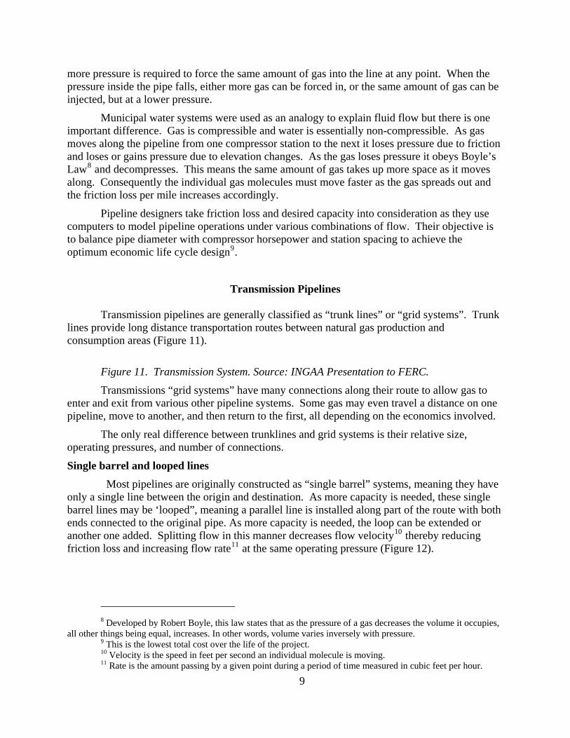
Single barrel and looped lines Most pipelines are originally constructed as “single barrel” systems, meaning they have
only a single line between the origin and destination. As more capacity is needed, these single barrel lines may be ‘looped”, meaning a parallel line is installed along part of the route with both ends connected to the original pipe. As more capacity is needed, the loop can be extended or another one added. Splitting flow in this manner decreases flow velocity10 thereby reducing friction loss and increasing flow rate11 at the same operating pressure (Figure 12).
8 Developed by Robert Boyle, this law states that as the pressure of a gas decreases the volume it occupies,
all other things being equal, increases. In other words, volume varies inversely with pressure. 9 This is the lowest total cost over the life of the project. 10 Velocity is the speed in feet per second an individual molecule is moving. 11 Rate is the amount passing by a given point during a period of time measured in cubic feet per hour.
9
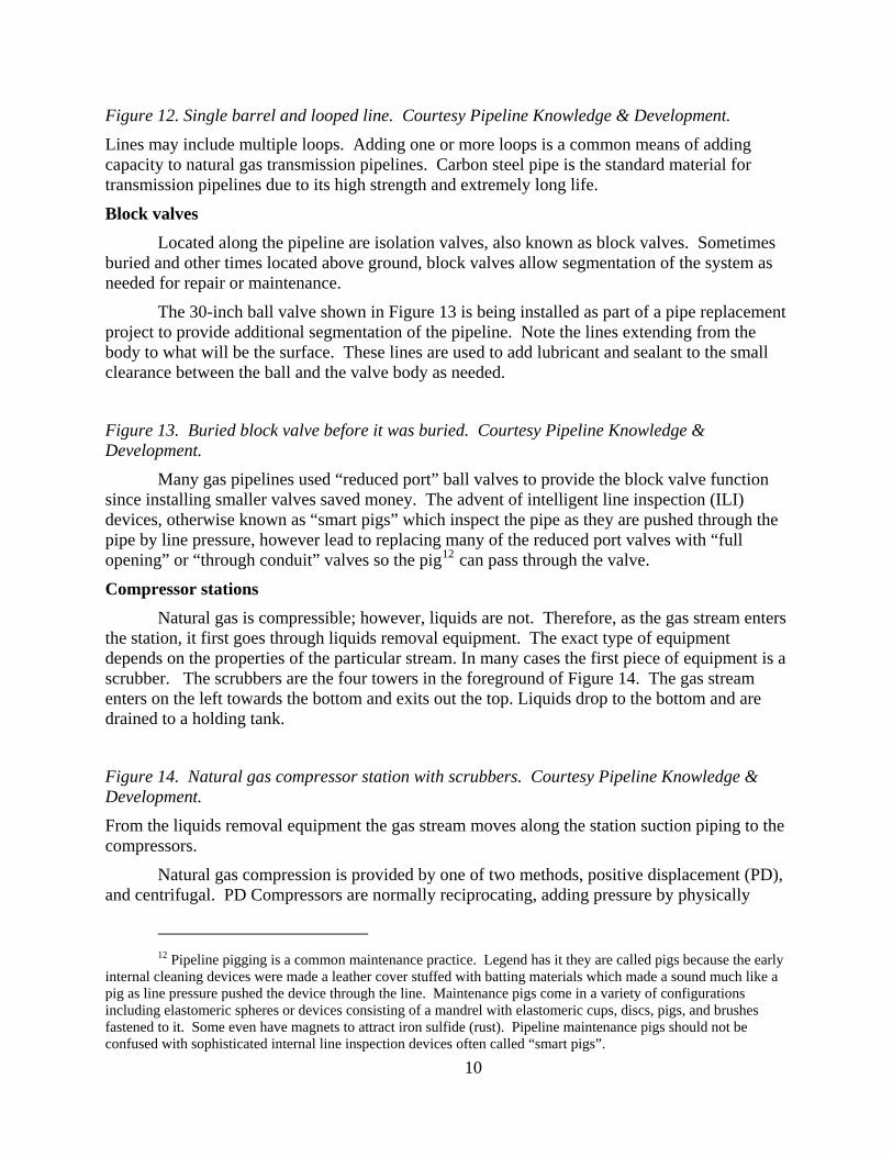
Figure 12. Single barrel and looped line. Courtesy Pipeline Knowledge & Development.
Lines may include multiple loops. Adding one or more loops is a common means of adding capacity to natural gas transmission pipelines. Carbon steel pipe is the standard material for transmission pipelines due to its high strength and extremely long life.
Block valves Located along the pipeline are isolation valves, also known as block valves. Sometimes
buried and other times located above ground, block valves allow segmentation of the system as needed for repair or maintenance.
The 30-inch ball valve shown in Figure 13 is being installed as part of a pipe replacement project to provide additional segmentation of the pipeline. Note the lines extending from the body to what will be the surface. These lines are used to add lubricant and sealant to the small clearance between the ball and the valve body as needed.
Figure 13. Buried block valve before it was buried. Courtesy Pipeline Knowledge & Development.
Many gas pipelines used “reduced port” ball valves to provide the block valve function since installing smaller valves saved money. The advent of intelligent line inspection (ILI) devices, otherwise known as “smart pigs” which inspect the pipe as they are pushed through the pipe by line pressure, however lead to replacing many of the reduced port valves with “full opening” or “through conduit” valves so the pig12 can pass through the valve.
Compressor stations Natural gas is compressible; however, liquids are not. Therefore, as the gas stream enters
the station, it first goes through liquids removal equipment. The exact type of equipment depends on the properties of the particular stream. In many cases the first piece of equipment is a scrubber. The scrubbers are the four towers in the foreground of Figure 14. The gas stream enters on the left towards the bottom and exits out the top. Liquids drop to the bottom and are drained to a holding tank.
Figure 14. Natural gas compressor station with scrubbers. Courtesy Pipeline Knowledge & Development.
From the liquids removal equipment the gas stream moves along the station suction piping to the compressors.
Natural gas compression is provided by one of two methods, positive displacement (PD), and centrifugal. PD Compressors are normally reciprocating, adding pressure by physically
12 Pipeline pigging is a common maintenance practice. Legend has it they are called pigs because the early
internal cleaning devices were made a leather cover stuffed with batting materials which made a sound much like a pig as line pressure pushed the device through the line. Maintenance pigs come in a variety of configurations including elastomeric spheres or devices consisting of a mandrel with elastomeric cups, discs, pigs, and brushes fastened to it. Some even have magnets to attract iron sulfide (rust). Pipeline maintenance pigs should not be confused with sophisticated internal line inspection devices often called “smart pigs”.
10

pushing the molecules closer together as a piston goes back and forth compressing the gas with each stroke. Sometimes reciprocating compressors and the engines driving them are integral, that is built into the same housing. They share a crank shaft between the engine and the compressor like the 2,500 HP V-10 engine integrated with a 3 cylinder double acting compressor shown in Figure 15.
Figure 15. Integral reciprocating engine and compressor. Courtesy Pipeline Knowledge & Development.
Other times reciprocating compressors are built separately and the engine is connected to the compressor with a shaft (Figure 16).
Figure 16. Reciprocating compressor connected to an engine with a shaft. Courtesy Pipeline Knowledge & Development.
In Figure 16 the compressor is in the foreground with the engine driver in the background. In this case the cylinders are working in series. The suction headers are not connected. The gas stream enters one cylinder where it is compressed and then it enters the other cylinder. Between cylinders, however, the gas is cooled since compression builds up heat.
Centrifugal compressors add pressure by first speeding up the gas molecules (adding kinetic energy) and then slowing them down thereby converting kinetic to potential energy. In Figure 17, the7,500 HP motor is on the left, the variable speed drive is in the center, and the compressor is on the right.
Figure 17. Centrifugal compressor driven by an electric motor through a variable speed drive. . Courtesy Pipeline Knowledge & Development.
Figure 18. Turbine driver. Courtesy Pipeline Knowledge & Development. Starting at the left top of Figure 18 is the starting turbine, the air compressor for the
engine air, six fire tubes, three on each side, and then the fans. The centrifugal compressor is off the Figure on the right. This turbine and compressor have been in service since circa 1959.
Compressor stations may have PD or centrifugal compressors or both.
The compressed gas exits the compressor building via the station discharge piping. In Figure 19, the suction header is the large diameter pipe extending from the bottom left to the center top of the figure. Each compressor is connected to the suction header. The discharge header is left of the suction piping and parallel to it. Discharge from the individual compressor units cross over the suction header and are connected to the discharge header.
Figure 19. Station suction and discharge piping. Courtesy Pipeline Knowledge & Development.
While much of the trunk lines can be inspected by ILI and cleaned by running maintenance pigs, almost none of the station piping can be. In addition to the main piping compressor and other
11
stations contain secondary piping, smaller diameter pipes installed to assist in normal station operating tasks such equalizing pressure in front of and behind maintenance pigs prior to launch or evacuating the main station pipeline or facilities as part of normal operations or maintenance activities (Figure 20).
Figure 20. Station piping. Courtesy Pipeline Knowledge & Development.
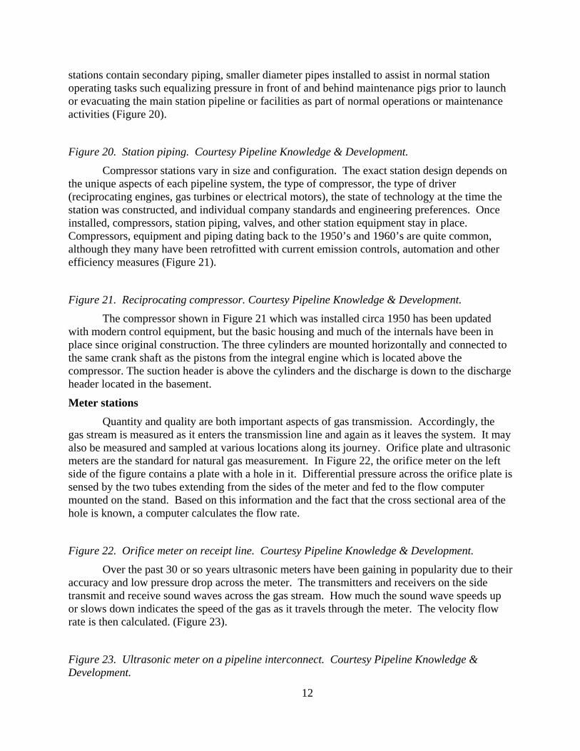
Compressor stations vary in size and configuration. The exact station design depends on the unique aspects of each pipeline system, the type of compressor, the type of driver (reciprocating engines, gas turbines or electrical motors), the state of technology at the time the station was constructed, and individual company standards and engineering preferences. Once installed, compressors, station piping, valves, and other station equipment stay in place. Compressors, equipment and piping dating back to the 1950’s and 1960’s are quite common, although they many have been retrofitted with current emission controls, automation and other efficiency measures (Figure 21).
Figure 21. Reciprocating compressor. Courtesy Pipeline Knowledge & Development.
The compressor shown in Figure 21 which was installed circa 1950 has been updated with modern control equipment, but the basic housing and much of the internals have been in place since original construction. The three cylinders are mounted horizontally and connected to the same crank shaft as the pistons from the integral engine which is located above the compressor. The suction header is above the cylinders and the discharge is down to the discharge header located in the basement.
Meter stations Quantity and quality are both important aspects of gas transmission. Accordingly, the
gas stream is measured as it enters the transmission line and again as it leaves the system. It may also be measured and sampled at various locations along its journey. Orifice plate and ultrasonic meters are the standard for natural gas measurement. In Figure 22, the orifice meter on the left side of the figure contains a plate with a hole in it. Differential pressure across the orifice plate is sensed by the two tubes extending from the sides of the meter and fed to the flow computer mounted on the stand. Based on this information and the fact that the cross sectional area of the hole is known, a computer calculates the flow rate.
Figure 22. Orifice meter on receipt line. Courtesy Pipeline Knowledge & Development.
Over the past 30 or so years ultrasonic meters have been gaining in popularity due to their accuracy and low pressure drop across the meter. The transmitters and receivers on the side transmit and receive sound waves across the gas stream. How much the sound wave speeds up or slows down indicates the speed of the gas as it travels through the meter. The velocity flow rate is then calculated. (Figure 23).
Figure 23. Ultrasonic meter on a pipeline interconnect. Courtesy Pipeline Knowledge & Development.
12

Interconnect stations. In addition to receiving gas from producing areas and delivering it to consumption locations, interstate natural gas transmission pipelines deliver to and receive from each other and from intrastate natural gas transmission lines at multiple points along their system as they fulfill their transportation function. Figure 24, depicts a rather small interconnect where two major gas transmission pipelines connect to each other.
Figure 24. Interconnect station. Courtesy Pipeline Knowledge & Development.
Interconnects are by definition a connection point between the transmission company and the receiving party (e.g., another pipeline, distribution company or other customer). Interconnects vary in size and complexity. For example, a small interconnect may only include the meter used for gas measurement, while large interconnects (including hubs) can include piping and meters to multiple pipelines, regulators, line heaters used to re-heat the natural gas stream that has cooled from pressure reductions, liquids separation and collection facilities, and other appurtenant facilities. Several companies can own the equipment and are responsible for operation of their individual assets at a single interconnect location. Custody transfer of the natural gas also occurs at the interconnect location.
Hubs. Connection of many pipelines to each other at one location is commonly called a hub. Hubs facilitate purchases, sales, and exchanges by enabling the physical movement of natural gas between pipelines (Figure 25).
Figure 25. Natural gas hub. Courtesy Pipeline Knowledge & Development.
City gate stations. City or town gate stations are where transmission companies deliver to local distribution companies. The pipeline customer typically provides measurement, pressure reduction, and quality control functions. Custody of the gas is transferred to the customers at this point. Often the odorant which gives natural gas its distinctive smell is added at gate stations. Two pipelines deliver through the city gate in Figure 26. The large pipe in the foreground is the incoming line from one of them.
Figure 26. City gate station. Courtesy Pipeline Knowledge & Development.
Other stations In addition to the stations listed, block valve stations, pigging stations, and crossover
stations are located along the line as needed. These stations are securely fenced and the valves locked for security purposes (Figure 27).
Figure 27. Block valve station. Courtesy Pipeline Knowledge & Development.
The block valve shown in Figure 27 is buried. Actuators which can close the valve in the event of an emergency are on top of the valve stem. Natural gas block valves commonly have a bypass installed to allow pressure equalization across the valve before it is opened. The bypass is the vertical pipe with the valves installed and the horizontal pipe connected to it.
13

Storage Natural gas wells produce continuously over the year, but gas usage varies by season and
by time of day. Natural gas usage has historically been highest in the winter and lowest in the summer. It is withdrawn from storage reservoirs during the fall and winter (withdrawal seasons) which are replenished during the spring and summer (injection season) as shown in Figure 28.
Figure 28. Natural gas storage in use. Prepared by Pipeline Knowledge & Development from EIA data.
The rising use of natural gas as a fuel for electrical power generation has created year round storage withdrawal demand.
Depleted gas reservoirs are the primary storage type. Salt caverns, aquifers, and LNG facilities also provide storage. “Cushion gas” or “base gas" must always remain in the reservoir so pressure remains at levels which maintain the structural integrity of the storage. The difference between total storage capacity and cushion gas is the “working capacity” of the storage. “Injection rate” is the amount of gas which can be added during a given time period without compromising the structure, and “deliverability rate” is the amount of gas which can be withdrawn during a given time period without compromising the structure.
In addition to adding and withdrawing gas seasonally, gas may be withdrawn from storage in the morning as people wake up and prepare for work and then added to storage at night as energy demand declines. Cold weather creates more demand and temperate weather less.
Pipeline Components Natural gas transmission pipelines are custom design and constructed to meet the specific
needs established by the marketplace. The major components used to construct these lines include pipe, coatings, valves, compressors, drivers, meters, liquid management equipment, actuators, cathodic protection equipment, control equipment, and ancillary systems to provide compressed air. Compressors, drivers, and meters have already been discussed so this section will concentrate on the other components.
Pipe Controlled by American Petroleum Institute (API) standards, pipe either starts out as a
flat plate of steel which is formed into shape and then welded along the seam, or as a steel cylinder which then has a hole punched longitudinally through its middle. In either case, the metallurgy of the parent steel is carefully controlled for strength, ductility, and other properties. Pipe normally is manufactured in sections called “joints” which are approximately 40 feet long. The sections and welded together at the construction site (Figure 29).
Figure 29. Line pipe. Courtesy Pipeline Knowledge & Development.
Pipe strength is governed by the Specified Minimum Yield Strength (SMYS) of the steel from which it is made. The SMYS of X-42 pipe is 42,000 pounds per square inch (psi) for
14

example. Wall thickness, steel strength, pipe diameter and a safety factor are used to calculate the pipeline’s Maximum Allowable Operating Pressure (MAOP).13
Coatings Pipe is externally coated to keep it from rusting. For many years coal tar epoxy coating
was the standard. But, as technology progressed, Fusion Bond Epoxy (FBE) has largely taken the place of coal tar epoxy when new pipe is installed. FBE is applied by heating the pipe in the coating plant and then spraying a powder onto the pipe. The powder melts and flows around the pipe. Small sections are left uncoated at the end of each pipe joint until the joints are welded together. Then the uncoated area is sandblasted and coated (Figure 30).
Figure 30. FBE coated pipe with field coating applied to girth weld. Courtesy Pipeline Knowledge & Development.
Valves Valves perform various functions; block, control, check, and relief – each one is a
function not a valve type. The primary natural gas pipeline valve types are ball, gate, and plug. Nearly any type of valve can provide any of the functions, but some are better at one function and others at another. Ball valves are normally used to provide the block function in natural gas transmission pipelines for example, but gate valves could also be used.
Ball Valves. Ball valves consist of a steel ball with a hole through it. This quarter turn ball valve shown in Figure 31 is open when the longitudinal axis of the opening is parallel to flow and closed with the longitudinal axis is perpendicular to flow. Ball valves are used extensively in natural gas service to block flow. They are also used to control, that is modulate, flow rates. As the valve closes, it creates more friction loss thereby slowing flow. As it opens, less friction is generated so the flow increases.
Figure 31. Partially open ball valve. Courtesy Pipeline Knowledge & Development. Gate Valves. Also used extensively to block flow, the gate valve consists of a rounded
or rectangular gate or wedge which can be forced across the flow (Figure 32).
Figure 32. Partially open slab gate valve. Courtesy Pipeline Knowledge & Development. The view in Figure 32 looks into the valve body cavity. Flow is from the bottom left to
the top right. The seats against which the gate will seal are in the middle back. The gate will move down from the top to close. Body cavities trap liquids and normally contain a drain to flush the body cavity.
13 MAOP = (2 x t x SMYS)/D X SF where
t = wall thickness SMYS = specified minimum yield strength D = outside diameter SF = Safety factor (0.72, 0.6, 0.5. or 0.4 based on population density along the line)
15

Plug Valves. Plug valves are also quarter turn valves. Resembling ball valves in design, they have a tapered plug rather than a ball to stop flow. Rather than spring loaded seats, or pressure differential providing the sealing force, however, the tapered plug can be forced downward providing a tight mechanical seal between the plug and seats. After the plug is mechanically engaged, a cavity exists inside the plug and perpendicular to the flow. This cavity can be vented to the outside to verify that no flow is leaking past. The forced mechanical seal with the ability to verify sealing, makes plug valves a frequent choice for manifold segregation and custody transfer service. The reduced port feature of plug valves mean they are not used when unrestricted flow through the pipe to allow passages of internal line inspection devices is required (Figure 33).
Figure 33. Fully open plug valve. Courtesy Pipeline Knowledge & Development.
Check Valves. These unidirectional valves normally have a flapper which opens to allow flow in one direction but swings shut if when flow tries to reverse. They are used extensively in compressor stations to keep gas from flowing back through compressors. The direction of flow in Figure 34 is into the page.
Figure 34. Partially open swing check valve. Courtesy Pipeline Knowledge & Development. Actuators
Also sometimes called operators, actuators are mounted on the top of valves so the hand wheels do not have to be turned manually and so the valves can be operated remotely (Figure 35).
Figure 35. Actuator on a ball valve. Courtesy Pipeline Knowledge & Development.
The two primary types of actuators used in natural gas service are those operated by compressed air and those operated by gas line pressure. The principle of operation is rather simple. Compressed air or natural gas is introduced into a cylinder which is connected to the valve shaft. As the pressure from the line pushes the cylinder, the shaft turns. The actuator shown in Figure 35 is operated by line pressure.
Liquids management equipment Gas is compressible and liquids are essentially non-compressible. Compressors and some
of the other station equipment are design for gas service and not for liquid service, so gas transmission operators must remove liquids to prevent damage to their compressors and other equipment. The methods employed to prevent liquids from entering the gas stream, or to remove them if they are in the gaseous phase, depend on several factors. Station differences mean that not every pipeline or station deals with liquids in the same manner.
Transmission line liquids. Natural gas transmission pipeline liquids are comprised of three components hydrocarbon liquids, lubricating oils, and water. Hydrocarbon liquids enter
16

the transmission pipeline with the gas stream, but drop out when they reach their dew point during subsequent heating and cooling cycles. Accordingly, the farther the gas travels along the transmission system, the less hydrocarbon liquids remain in the stream. Lube oils enter the gas stream at compressor stations primarily across centrifugal compressor “wet seals”14 or as part of the cylinder and piston lubrication process in PD compressors15. Water vapor also enters the system with the gas stream and drops out as the gas moves along. These liquids are removed from the gas stream by several different types of equipment and several different methods”16. One word of caution, nomenclature is not always consistent for the various types of equipment across the industry.
Mainline drips. Pipeline drips are installed below the pipeline at low spots in the line where liquids are drawn by gravity. Since drips are connected to the pipeline, they are under line pressure. Drips are not needed on lines which are pig-able since pigs or spheres push the fluids through the pipeline and into the pig launcher. A number of pipeline drips have been removed as interstate natural gas transmission companies retrofit their lines to make them pig-able.
Slug catchers. Sometimes “slugs” of liquids condense from the stream and collect in low spots until they eventually fill up the pipeline and block the flow of gas. Pressure builds behind the slug until the differential between the pressure behind the slug and the pressure in front of the plug is sufficient to push the slug along. Figure 36 shows a slug catcher installed on a natural gas gathering system to catch liquids and prevent slug flow.
Figure 36. Pipeline slug catcher. Courtesy Pipeline Knowledge & Development.
Slug catcher design and sizing depends on factors such as pipeline diameter, flow rate, and expected liquid drop out. Slug catchers are drained into collection tanks on either an as needed or periodic basis. One slug catcher may have several lines connected to it.
Station drips. Station drips, also sometimes called drip pots or pots, are installed at meter stations to collect liquids so they do not damage or affect the accuracy of meters (Figure 37).
Figure 37 Station Drip. Courtesy Pipeline Knowledge & Development
The station drip shown in Figure 37 is relatively small because gas flow through this station is relatively low. Gas enters this drip pot shown in the center bottom of this pictures and exits through the top. Any liquids fall to the bottom and are removed through a small pipe using line pressure to push them out. The gas meters are located inside the building.
14 Centrifugal compressors have seals fastened to the compressor drive shaft and the compressor housing to
keep gas from escaping from the compressor. Instruments measure the pressure inside the compressor and maintain the oil pressure on the seals at a point approximately 10 psi above the pressure in the compressor. This pressure differential insures no gas leaks out into the compressor building. It also means a small amount of oil is continually forced into the clearance between the seal faces to keep gas from escaping along the shaft.
15 Small amounts of lubricating oil, on the order of several gallons per day, are intentionally injected into PD compressor cylinders to prevent wear and heat buildup.
16 For more on separation equipment see Section 7, Separation Equipment, Engineering Data Book, Gas Processors Association, Tulsa, OK
17
Drips continue in many meter stations, but are being removed from transmission lines as the lines are retrofitted to enable maintenance pig and ILI runs. Lines which can be pigged do not need drips as any liquids are pushed from the line and into pig receivers at compressor stations or other stations for handling.
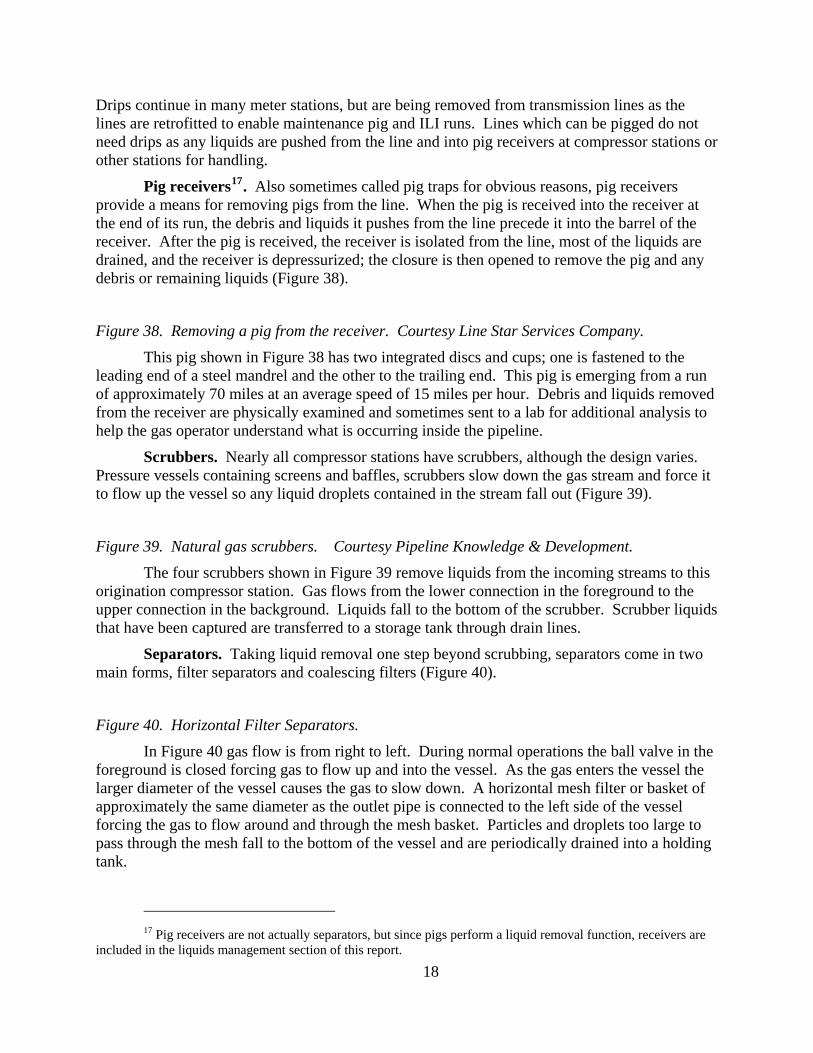
Pig receivers17. Also sometimes called pig traps for obvious reasons, pig receivers provide a means for removing pigs from the line. When the pig is received into the receiver at the end of its run, the debris and liquids it pushes from the line precede it into the barrel of the receiver. After the pig is received, the receiver is isolated from the line, most of the liquids are drained, and the receiver is depressurized; the closure is then opened to remove the pig and any debris or remaining liquids (Figure 38).
Figure 38. Removing a pig from the receiver. Courtesy Line Star Services Company.
This pig shown in Figure 38 has two integrated discs and cups; one is fastened to the leading end of a steel mandrel and the other to the trailing end. This pig is emerging from a run of approximately 70 miles at an average speed of 15 miles per hour. Debris and liquids removed from the receiver are physically examined and sometimes sent to a lab for additional analysis to help the gas operator understand what is occurring inside the pipeline.
Scrubbers. Nearly all compressor stations have scrubbers, although the design varies. Pressure vessels containing screens and baffles, scrubbers slow down the gas stream and force it to flow up the vessel so any liquid droplets contained in the stream fall out (Figure 39).
Figure 39. Natural gas scrubbers. Courtesy Pipeline Knowledge & Development.
The four scrubbers shown in Figure 39 remove liquids from the incoming streams to this origination compressor station. Gas flows from the lower connection in the foreground to the upper connection in the background. Liquids fall to the bottom of the scrubber. Scrubber liquids that have been captured are transferred to a storage tank through drain lines.
Separators. Taking liquid removal one step beyond scrubbing, separators come in two main forms, filter separators and coalescing filters (Figure 40).
Figure 40. Horizontal Filter Separators.
In Figure 40 gas flow is from right to left. During normal operations the ball valve in the foreground is closed forcing gas to flow up and into the vessel. As the gas enters the vessel the larger diameter of the vessel causes the gas to slow down. A horizontal mesh filter or basket of approximately the same diameter as the outlet pipe is connected to the left side of the vessel forcing the gas to flow around and through the mesh basket. Particles and droplets too large to pass through the mesh fall to the bottom of the vessel and are periodically drained into a holding tank.
17 Pig receivers are not actually separators, but since pigs perform a liquid removal function, receivers are
included in the liquids management section of this report.
18
Filter separators and coalescing filters perform essentially the same function. Filter separators are normally oriented horizontally and remove particles and droplets as small as 1 micron. Coalescing filters normally are oriented vertically and remove particles and droplets as small as 0.3 Microns. In several applications coalescing filters may be located downstream of filter separators for additional liquids removal.
Exposure points. Pipelines operate under pressure and are therefore inherently closed systems, so the general public is not exposed to pipeline liquids under normal operating conditions. Pipeline company and contractor employee’s exposure to pipeline liquids under normal operating conditions is limited to times when they are removing pigs from pig receivers, sampling generated liquids, draining liquid removal equipment such as drips when the drains are not directly connected to liquid storage tanks, and performing maintenance operations.
Separation equipment however is normally connected by pipes to storage tanks, so employees are not exposed to liquids when they are transferred from separation equipment to the storage tanks. Liquids are normally loaded onto transport trucks from the storage tanks through hoses, so employees would only be exposed to liquids if an upset condition occurred during loading. Any time pipeline company or contractor employees face potential exposure they wear Personal Protective Equipment (PPE) such as gloves, face shields, respirators, and protective clothing. All liquid transfer operations are conducted using detailed operating procedures to insure safety.
Cathodic protection equipment Pipelines are made of steel and susceptible to corrosion. The same electro chemical
reaction which causes current to flow in batteries will also cause pipelines to rust if the pipelines are not properly protected. So, the answer to preventing corrosion is to either preventing current flow, forcing the current to flow in the desired direction; pipelines employ a combination of the two. Preventing current flow is accomplished with pipeline coatings. Coating technology has been in use protecting pipelines from corrosion since the early 1900’s.
Pipeline operators have used the differences in electrical potential between iron, the principal component of steel, and other substances, for many years to protect pipelines from corrosion. In some cases magnesium bars or bags of magnesium are connected to the steel line along its route. The difference in electrical potential between the steel and magnesium sets up an electrical flow which sacrifices the magnesium to keep the steel from corroding.
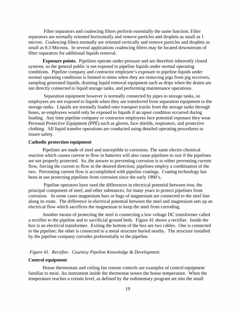
Another means of protecting the steel is connecting a low voltage DC transformer called a rectifier to the pipeline and to sacrificial ground beds. Figure 41 shows a rectifier. Inside the box is an electrical transformer. Exiting the bottom of the box are two cables. One is connected to the pipeline; the other is connected to a metal structure buried nearby. The structure installed by the pipeline company corrodes preferentially to the pipeline.
Figure 41. Rectifier. Courtesy Pipeline Knowledge & Development.
Control equipment
House thermostats and ceiling fan remote controls are examples of control equipment familiar to most. An instrument inside the thermostat senses the house temperature. When the temperature reaches a certain level, as defined by the rudimentary program set into the small
19

microprocessor in the thermostat, a signal is sent to a switch which opens or closes to turn the power to the air-conditioner on heater on or off.
Similarly, but on a much more sophisticated level, natural gas transmission pipelines use controls. Many of the instruments or switches are electrical or electronic, but some are air activated.18 Instruments and switches are connected to Supervisory Control and Data Acquisition (SCADA) systems which acquire data about pipeline operating conditions and send that information to either computers or humans to make decisions. After the decision is made, the SCADA system sends that decision to the device which will carry out the decision. When the pressure to a delivery point falls below a preset level for example, the SCADA system may automatically start another compressor or may send a signal to the central control room operators who then decides what action to take.
Compressed air systems Compressed air is used for three purposes in natural gas compressor stations, starting
engines (but not turbines), powering instruments and devices (like valve actuators), and general work purposes such as powering hand tools. Compressor stations with engine drivers use much more air than do other stations since air is introduced into the engine cylinders to get the engine moving before the pistons begin firing. Compressor stations normally have two air compressors for redundancy (Figure 42).
Figure 42. Air compressors in compressor station with engine drivers. Courtesy Pipeline Knowledge & Development.
Since large amounts of air are needed to start the large reciprocating engine drivers turning, accumulator tanks are used to store the air so the amount needed is available (Figure 43).
Figure 43. Compressed air storage cylinders. Courtesy Pipeline Knowledge & Development.
The cylinders on the right hold air dedicated to starting engines. Those on the right are used for instrument and auxiliary air which require smaller volumes of air than starting engines. Note the elevated lube oil tank in the center of the picture.
Instrument air is typically dried (moisture removed) to prevent internal corrosion of expensive instrumentation. It is then piped to individual control instruments which are usually grouped together for ease of piping and maintenance. These nine air valves shown in Figure 44 are located in the basement of a reciprocating engine station.
Figure 44. Instrument air control manifold. Courtesy Pipeline Knowledge & Development.
Liquids sampling points
As mentioned earlier, pipeline and station design varies based on a number of factors, so any individual pipeline or station will likely be different when it comes to liquids removal,
18 For more on controls see, Miesner, T. O. and Leffler, W. L., (2006) Oil and Gas Pipelines in
Nontechnical Language, PennWell Publishing , Tulsa, OK, Chapter 8, SCADA, Controls and Leak Detection
20
sampling, and storage. In some cases essentially all the water and hydrocarbon liquids have condensed from the natural gas stream before it reaches the natural gas transmission pipeline, particularly those located remote from production area.
Most pipeline liquids collected in stations are connected by pipes to a central collection tank. This tank operates at near atmospheric pressure so a composite sample of the fluids removed at the station can be obtained rather easily, simply by draining some liquids from the tank into a flask. If individual gas steams or pieces of equipment need to be sampled, special arrangements must be made. A generic description of the potential sampling points follows.
• Mainline drips are directly connected to the pipeline and therefore under pipeline pressure. Consequently they cannot safely be sampled directly. The fluids must be drained into a collection tank which is then reduced to atmospheric pressure before a sample can be withdrawn.
• Meter station drips are smaller than pipeline drips and can be either above or below ground. Station drips are not normally piped to collection tanks; rather they are drained to a portable container making sampling easier. Meter drips however may collect liquids from several lines.
• Scrubbers and separators at compression stations are typically configured to remove liquids either from the lines as they enter the station or immediately prior to individual compressor units. In either case, extensive re-piping would be required to redirect individual pipelines to individual scrubbers or scrubber banks.
• Pig receivers normally serve individual lines for operating reasons. Once the pig arrives, the receiver can be depressurized and liquid, if any, can be manually sampled. Not all pipeline segments are pig-able however and, for those that are; pigging frequencies vary widely as established by the specific operating conditions of the line in question.
Pipeline and Station Operations Distributed at various locations along the pipeline route are small offices from which the
field operating staff is based. These people, assisted by contractors as needed, operate and maintain the pipelines19.
Field Operations Field operating duties include; measurement, testing and quality control, pipeline
cleaning and pigging, line control, liquids management (collection, removal, and handling) relations with the public, security, right-of-way maintenance, and a myriad of other duties all aimed at safe, reliable, efficient operation in an environmentally responsible manner.
19 Operations cause the pipeline to function such that it performs its intended purpose. Maintenance keeps
the pipeline in operating condition at its current capacity. Field operations are those conducted along or near the pipeline’s route. Some maintenance activities such as planning are conducted remote from the pipeline but most maintenance activities are conducted along the route. Control room operations are conducted at limited numbers of locations remote from the pipeline. Operations and maintenance are often performed by the same field people.
21

Central control room operations SCADA systems feed information about how the line is operating (pressures, flow rates,
gas quality, driver and compressor status, valve positioning, and a host of other operating parameters to the central control room. This information is displayed on screens which are constantly monitored by control room operators (Figure 45).
Figure 45. Control room operating console. Courtesy Pipeline Knowledge & Development.
Some operating decisions are made automatically by the SCADA system, modulating a control valve for example to maintain pressures at preset levels. Other decisions are reserved for the human operator. Eight different screens can be displayed at one time on the console shown in Figure 45. Some screens provide information to the operator. Others allow the operator to click on an icon representing a piece of equipment which brings up a dialogue box which the operator than uses to start or stop equipment or make other control moves.
Pipeline and Station Maintenance The development of technology over the past forty or fifty years has changed the
definition of maintenance from “fix it when it breaks” to “fix it before it breaks”. Instrumentation and computer modeling has progressed to the point where maintenance personnel focus on understating the condition of the asset and taking corrective actions to prevent failures. If failures do happen, company employees either make the repairs themselves, or supervise contractors who make the repairs.
Pipeline maintenance Since the advent of Internal Line Inspection (ILI) tools20 in the 1960’s (sometimes also
called smart pigs) pipeline operators can obtain information about the pipeline’s condition without having to dig it up. ILI tools flow through the line along with the gas. As they move along, the tools inspect the pipe wall for potential defects, commonly called anomalies. Interstate natural gas transmission companies do not commonly own the inspection tools. Rather, they contract with ILI vendors. Shortly after the ILI run in a particular section of pipe is completed, the vendor gives the company a report indicating the location and severity of any anomalies. Integrity engineers use these reports to plan their pipeline maintenance programs.
Some pipeline segments, and nearly all station piping, is “non-pig-able”, meaning the pipe turns and restrictions in the lines are such that ILI tools cannot transit those sections. In the case of non-pig-able lines, pressure testing, direct assessment, and other proven technologies are used to determine line condition. If anomalies are detected, strict regulations, along with industry standards and company programs, establish the protocols regarding how those anomalies must be addressed.
Buried steel pipe would corrode if not protected so, monitoring the operation of, and maintaining cathodic protection, primarily coating, rectifiers, and ground beds is a key
20 Magnetic flux technology (MFL) is the primary ILI technology used to inspect interstate natural gas
pipelines. As the tool travels through the pipe, it temporarily magnetizes the section it is passing through. Sensors located on the tool record differences in the magnetic flux the pipe can contain. Loss of flux in an area indicates a reduction in the amount of metal present.
22
maintenance task. Properly protected from corrosion, the life of steel pipe is not infinite, but it is quite long, on the order of hundreds of years.
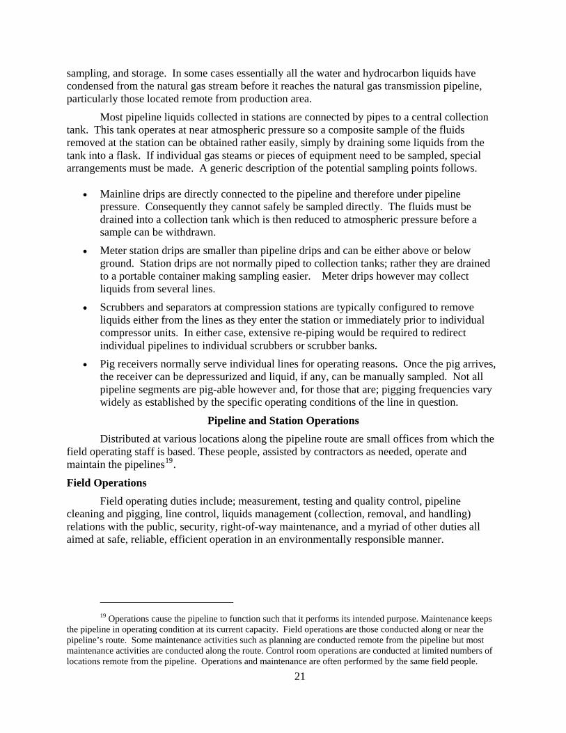
If corrosion or other defects are found during ILI runs, the affected piece of the pipeline is unearthed to be visually inspected. If necessary, it is repaired or replaced enabling the repaired or replaced section, along with the balance of the pipeline, to continue providing safe and reliable service for many years. Figure 46 shows a section of pipeline being cut out and replaced with a new piece of pipe. The pipe on the right bank is a by-pass installed temporarily to maintain gas flow around the cut out section.
Figure 46. Replacing a piece of pipe. Courtesy Pipeline Knowledge & Development.
In addition to preventing corrosion and monitoring and repairing line condition, pipeline maintenance includes many other components such as line lowering, right-of-way surveillance and clearing, and line cleaning also sometimes called maintenance pigging (Figure 47).
Figure 47. Loading a cleaning pig. Courtesy Pipeline Knowledge and Development.
Station maintenance Just as cars required regular maintenance, care, and sometimes repair, so do the myriad of
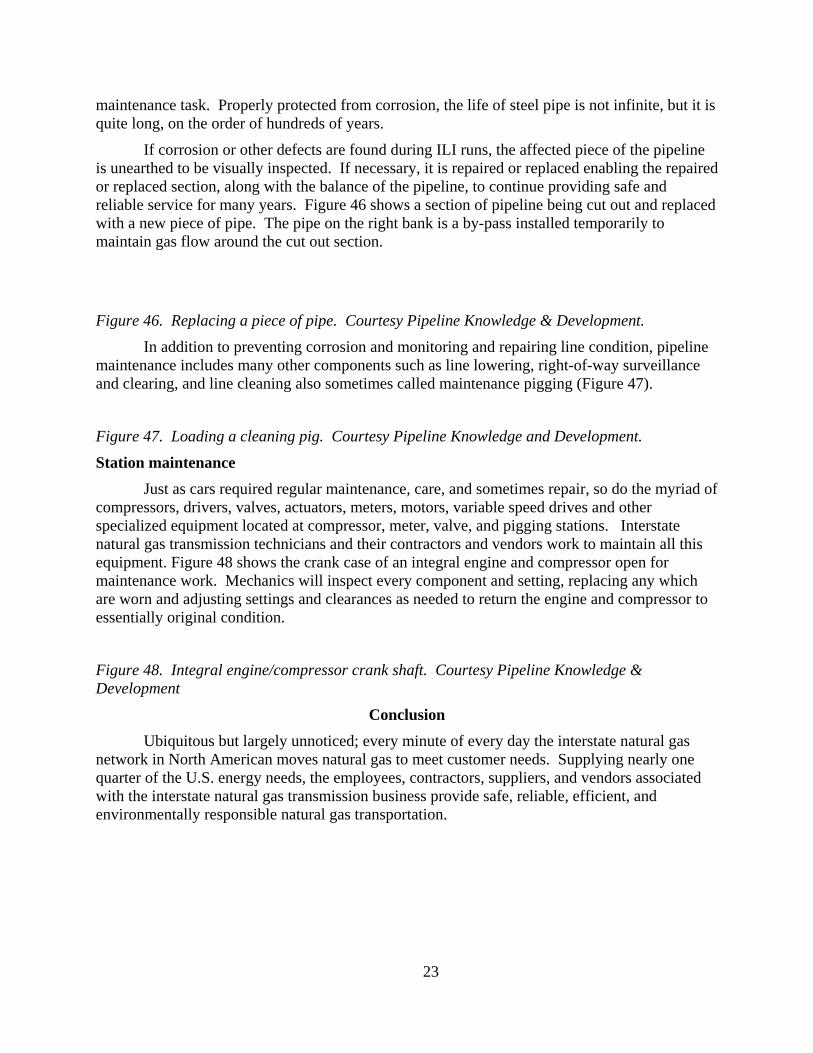
compressors, drivers, valves, actuators, meters, motors, variable speed drives and other specialized equipment located at compressor, meter, valve, and pigging stations. Interstate natural gas transmission technicians and their contractors and vendors work to maintain all this equipment. Figure 48 shows the crank case of an integral engine and compressor open for maintenance work. Mechanics will inspect every component and setting, replacing any which are worn and adjusting settings and clearances as needed to return the engine and compressor to essentially original condition.
Figure 48. Integral engine/compressor crank shaft. Courtesy Pipeline Knowledge & Development
Conclusion
Ubiquitous but largely unnoticed; every minute of every day the interstate natural gas network in North American moves natural gas to meet customer needs. Supplying nearly one quarter of the U.S. energy needs, the employees, contractors, suppliers, and vendors associated with the interstate natural gas transmission business provide safe, reliable, efficient, and environmentally responsible natural gas transportation.
23

Appendix A21 The History of Natural Gas Transmission Rates
The revenue equation is classically quantity multiplied by price (rate), and natural gas transmission lines are no exception. Natural gas transmission rates, the price per quantity shipped, have been tightly intertwined with regulations ever since 1935 when passage of the Public Utility Holding Company Act gave the federal government jurisdiction over the companies owing these lines – but not over the lines themselves. Three years later, however, passage of the Natural Gas Act gave the Federal Power Commission (FPC) authority to directly regulate the lines. Armed with the power to regulate but only the sketchy instructions that rates charged by interstate natural gas pipelines must be “just and reasonable”, the FPC experimented with methods to carry out their regulatory mandate.
The gas pipeline business model of the time consisted of more than simply charging for natural gas transportation and storage services. Rather, the pipeline companies purchased gas from producers, transported it to customers (storing it along the way if required), and sold it at a “bundled” price. The entire process from the well head purchase price to the final customer price was regulated. Regulatory schemes that sounded simple and straight forward enough – allow cost recovery and a fair return on investment – proved difficult to implement.
Finally, forty years after passage of the Natural Gas Act, the Natural Gas Policy Act (NGPA) was passed by Congress in 1978. It abolished the Federal Power Commission replacing it with the Federal Energy Regulatory Commission (FERC) ushering in a new age of pipeline regulations (and rates). The NGPA had three primary objectives;
• create a single national natural gas market,
• allow market forces rather than regulations to establish the market price of natural gas, and
• Balance natural gas supply and demand.
These three objectives sounded simple enough but the devil is always in the details and between 1978 and 1992, the newly formed FERC and the industry struggled to transform the natural gas business. The turbulent1980’s saw a new market driven model begin to evolve as the FERC issued orders and industry struggled to comply. Lawsuits abounded among regulators, gas transmission companies, producers, and consumers. One story related to the author typifies this period; the vice president of operations for a natural gas pipeline company called the vice president of natural gas at a producing company, inviting him to speak at an industry conference and golf in his foursome, and informing him the transmission company was suing the producing company to settle a contract – all in the same phone call.
Finally in 1992 the FERC issued Order 636. Sometimes referred to as the Final Restructuring Rule, Order 636 completed the process of “unbundling” natural gas prices from the
21 Taken from Miesner, Tom, (2009) A Practical Guide to US Natural Gas Transmission Pipeline
Economics, PennEnergy,
24

cost of transporting and storing it. Natural gas prices have been decontrolled but transportation and storage rates and services continue to have regulated components.
Order 636 fundamentally changed then natural gas business, including natural gas pipelines and subsequent orders have been needed to clarify how various aspects of the industry should function. Appendix B contains a summary of the various FERC orders affecting natural gas pipelines since 1992. One of the major changes promulgated by Order 636 was electronic bulletin boards. They may have seemed a novelty in 1992 when the FERC issued Order 636 but now are indispensible communication and management tools.
“Just and Reasonable” The Natural Gas Act (NGA) required that rates charged by interstate pipeline must be
"just and reasonable". Economic theory proposes any entity with market power should be regulated to prevent abuse of that power. Back in 1906 for example, Congressman Charles Townsend wrote an article for the New York Times discussing the monopolies of the railroads and the need to for the Interstate Commerce Commission to regulate their rates.22
The large capital investments needed to construct transmission pipelines, along with the economies of scale associated with operating larger diameter pipelines, suggests the number of pipelines extending from individual supply sources to demand centers will be limited. Early regulators thought of natural gas pipelines as “natural monopolies” leading them to conclude the Cost of Service (COS) theory of rate regulation was the appropriate approach. In a nutshell the COS approach allows companies to recover their expenses and earn a “fair” return on their equity23. Under COS all costs are totaled and divided by total quantities to calculate individual rates. But, with multiple rate categories and locations allocating costs between the categories and locations can become complex. Natural gas pipeline and storage companies have departments which specialize in keeping up with rates and rate related developments as does the FERC. There are also consulting companies ready to provide expertise and assistance as requested.
22 Townsend, Charles E... (January 7, 1906). Government Rate Making for the Railroads, The New York
Times 23 In June of 1999 the FERC published a Cost of Service Manual, which can be downloaded at
www.ferc.gov/industries/gas/gen-info/cost-of-service-manual.doc
25

Appendix B24 Key FERC Orders, 1992-2008
Date Issued Order No. Effect of Order
1992 Order 636 Required interstate pipeline companies to provide open access transportation and storage and to separate sales and transportation services completely. Mandated capacity release, electronic bulletin boards, and straight fixed-variable rate design (where all fixed transmission and storage costs are billed through the pipeline's reservation charge).
1994 Order 563 Consolidated requirements for standardized electronic bulletin boards (EBB) and downloadable files set under Order 636.
Gathering Policy Orders
Issued several orders clarifying FERC's gathering policy. Determined it did not have jurisdiction over gathering affiliates of interstate pipelines. Retained the right to disregard the separate corporate structures if a pipeline company abuses the pipeline/affiliate interrelationship.
1998 Order 587 Required all interstate pipeline companies to implement fully functional Web sites to replace their current EBB systems by June 1, 2000. Established scheduling priority for intraday nominations. Incorporated most recent standards of Gas Industry Standards Board (GISB).
2000 Order 637 Allowed capacity holders to trade their rights in secondary market transactions. Suspended price caps for the sale of short term (less than one year) released capacity until September 30, 2002. Refined regulations for segmenting capacity to give shippers more flexibility and expanded pipeline reporting requirements on market transactions to increase market transparency.
2002 Order 637 Decided not to lift the price caps on capacity release transactions after 2-year pilot.
2003 Order 2004 Established combined standards of conduct for electric public utilities and interstate natural gas pipeline companies. Broadened the definition of an energy affiliate to include both physical and financial transactions by marketing and non-marketing pipeline affiliates.
Order 644 Addressed standards of ethical behavior applicable to buying and selling natural gas and reporting data. Prohibits actions that are
24 Taken from Miesner, Tom, (2009) A Practical Guide to US Natural Gas Transmission Pipeline
Economics, PennEnergy,
26

without a legitimate business purpose and could manipulate market prices or conditions, such as "wash" trades and collusion. Gas sellers are not required to report trade data to index publishers, but if they do so, they must provide accurate, complete and factual information.
2004 Order 2004 On rehearing (April 2004) FERC reaffirmed the need for the rule and clarified that it does not apply to affiliate gatherers, processors, and intrastate pipelines that have interactions with transmission pipelines but do not "engage in" nor are "involved in" transmission transactions. FERC upheld the rule's provisions that allow shared employees, such as officers and directors, to receive non-public operational information as long as they do not act as a conduit for sharing that information. The date for full compliance was extended from June 1, 2004, to September 1, 2004.
2005 Order 2005 Reaffirmed and clarified FERC rules establishing requirements
governing the conduct of open seasons for capacity for future Alaska natural gas pipeline projects.
2006
Order 673 Rescinded various sections of 644 regarding selling of unbundled natural gas sales services which were no longer needed after passage of the Energy Policy Act of 2005 gave the FERC anti-manipulative power over the same matters.
Order 678 Included a more expansive definition of the relevant product market for storage that would include, to the extent they can be shown to be good substitutes for storage, available pipeline capacity, local gas production and liquefied natural gas terminals and allows an applicant to request authority to charge "market-based rates even if a lack of market power has not been demonstrated, in circumstances where market-based rates are in the public interest and necessary to encourage the construction of storage capacity
Order 682 Required that jurisdictional natural gas companies report damage to facilities as the result of a natural disaster or terrorist activity that results in a reduction in pipeline throughput or storage deliverability.
Order 686 Expanded the types of natural gas projects permitted under blanket certificate authority and increased the cost limits that apply to blanket projects. Also clarified that a natural gas company is not necessarily engaged in an unduly discriminatory practice if it charges different customers different rates for the same service based on the date thatcustomers commit to service. Allowed interstate natural gaspipelines to employ the streamlined blanket certificate procedures for larger projects and for a wider variety of types of projects.
Order 687 Establish a process for developing schedules for the completion of reviews of requests for authorizations for proposed projects and compiling a consolidated record.
2007 Order 698 Mandated certain voluntary standards already promulgated by the
27

28
North American Energy Standards Board (NAESB) which established communication protocols between interstate pipelines and gas fired power plants.
Order 700 Modified landowner notification requirements and required a noise survey following the completion of projects involving compressor facilities undertaken pursuant to blanket certificate authority
Order 704 Required certain natural gas market participants to report information regarding; their reporting of transactions to price index publishers, and their blanket sales certificate status, and to report annually certain information regarding their wholesale, physical natural gas transactions for the previous calendar year.
2008
Order 710 Revised the requirement for natural gas company financial forms, statements and reports to enhance the forms’ usefulness by updating them to reflect current market and cost information relevant to interstate natural gas pipelines and their customers.
Order 712 Permanently lifted the maximum rate ceiling on capacity releases of one year or less. Promoted the use of asset management arrangements (AMA) under which a capacity holder releases some or all of its capacity to an Asset Manager. Revised the FERC’s prohibition against tying. Modified the FERC’s regulations by exempting capacity releases made under state-approved retail programs from the capacity release bidding requirements and prohibition against tying.
Order 720 Required certain major non-interstate natural gas pipelines to post daily scheduled volume information and design capacity for certain points. Also revised regulations to require interstate natural gas pipelines to post information regarding the provision of no-notice service.
Note: In many cases FERC orders are followed with re-hearings and clarifications. These are listed as the original order number followed by a letter as in Order 636 A. Re-hearings and clarifications are not listed separately in this table but are rather incorporated with the original order.
This appendix was developed from information contained on the FERC web site. See http://www.ferc.gov/legal/maj-ord-reg.asp for more details.
Related Documents