4. The Integral Equations 4.1. INTRODUCTION Fluid mechanics is encountered in almost every area of our physical lives. Many, if not most, of the quantities of interest are integral quantities; they are found by integrating some property of interest over an area or a volume. Many times the property is essentially constant so the integration is easily performed but other times, the property varies over the area or volume and the required integration may be quite difficult. What are some of the integral quantities of interest? The rate of flow through a pipe, the force on the vertical surface of a dam, the kinetic energy in the wind approaching a wind machine, the power generated by the blade of a turbine, the force on the blade of a snowplow, and the drag on an airfoil, to mention a few. There are quantities that are not integral in nature, such as the minimum pressure on a body or the point of separation on an airfoil; quantities such as these will be considered in Chap. 5. To perform an integration over an area or a volume, it is necessary that the integrand be known. The integrand must either be given or information must be available so that it can be approximated with an acceptable degree of accuracy. There are numerous integrands where acceptable approximations cannot be made requiring the solutions of differential equations to provide the required relationships; external flow calculations, such as the lift and drag on an airfoil, often fall into this category. Some relatively simple integrals requiring solutions to the differential equations will be included in Chap. 5. In this chapter, only those problems that involve integral quantities with integrands that are given or that can be approximated will be considered. 4.2. SYSTEM-TO-CONTROL-VOLUME TRANSFORMATION The three basic laws that are of interest in fluid mechanics are often referred to as the conservation of mass, energy, and momentum. The last two are more specifically called the first law of thermodynamics and Newton's second law. Each of these laws is expressed using a Lagrangian description of motion; they apply to a specified mass of the fluid. They are stated as follows: Mass: The mass of a system remains constant. Energy: The rate of heat transfer to a system minus the work rate done by a system equals the rate of change of the energy E of the system. Momentum: The resultant force acting on a system equals the rate of momentum change of the system. Each of these laws will now be stated mathematically recognizing that the rate of change applies to a collection of fluid particles and the fact that the density, specific energy, and velocity can vary from point to point in the volume of interest. This requires the material derivative and integration over the volume (4.1) (4.2) © McGraw-Hill Education. All rights reserved. Any use is subject to the Terms of Use, Privacy Notice and copyright information.

Welcome message from author
This document is posted to help you gain knowledge. Please leave a comment to let me know what you think about it! Share it to your friends and learn new things together.
Transcript
4. The Integral Equations
4.1. INTRODUCTION
Fluid mechanics is encountered in almost every area of our physical lives. Many, if not most, of the quantities of interest areintegral quantities; they are found by integrating some property of interest over an area or a volume. Many times the property isessentially constant so the integration is easily performed but other times, the property varies over the area or volume and therequired integration may be quite difficult.
What are some of the integral quantities of interest? The rate of flow through a pipe, the force on the vertical surface of a dam,the kinetic energy in the wind approaching a wind machine, the power generated by the blade of a turbine, the force on the bladeof a snowplow, and the drag on an airfoil, to mention a few. There are quantities that are not integral in nature, such as theminimum pressure on a body or the point of separation on an airfoil; quantities such as these will be considered in Chap. 5.
To perform an integration over an area or a volume, it is necessary that the integrand be known. The integrand must either begiven or information must be available so that it can be approximated with an acceptable degree of accuracy. There arenumerous integrands where acceptable approximations cannot be made requiring the solutions of differential equations toprovide the required relationships; external flow calculations, such as the lift and drag on an airfoil, often fall into this category.Some relatively simple integrals requiring solutions to the differential equations will be included in Chap. 5. In this chapter, onlythose problems that involve integral quantities with integrands that are given or that can be approximated will be considered.
4.2. SYSTEM-TO-CONTROL-VOLUME TRANSFORMATION
The three basic laws that are of interest in fluid mechanics are often referred to as the conservation of mass, energy, andmomentum. The last two are more specifically called the first law of thermodynamics and Newton's second law. Each of theselaws is expressed using a Lagrangian description of motion; they apply to a specified mass of the fluid. They are stated asfollows:
Mass: The mass of a system remains constant.
Energy: The rate of heat transfer to a system minus the work rate done by a system equals the rate of change of the energyE of the system.
Momentum: The resultant force acting on a system equals the rate of momentum change of the system.
Each of these laws will now be stated mathematically recognizing that the rate of change applies to a collection of fluidparticles and the fact that the density, specific energy, and velocity can vary from point to point in the volume of interest. Thisrequires the material derivative and integration over the volume
(4.1)
(4.2)
© McGraw-Hill Education. All rights reserved. Any use is subject to the Terms of Use, Privacy Notice and copyright information.
(4.3)
where the dot over Q and W signifies a time rate and e is the specific energy included in the parentheses of Eq. (1.33). It is verydifficult to apply Eqs. (4.1) to (4.3) directly to a collection of fluid particles as the fluid moves along in either a simple pipe flowor the more complicated flow through a turbine. So, let us convert these integrals that are expressed using a Lagrangiandescription to integrals expressed using an Eulerian description (see Sec. 3.2.1). This is a rather tedious derivation but animportant one.
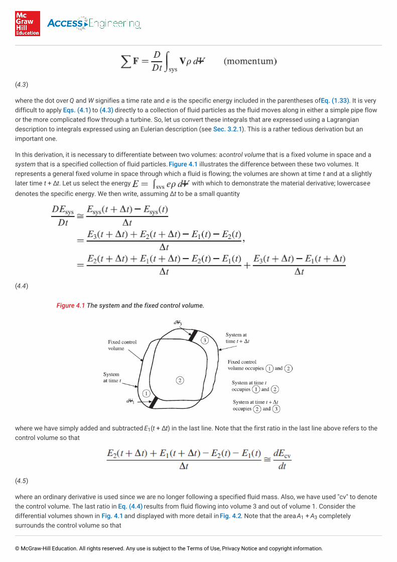
In this derivation, it is necessary to differentiate between two volumes: a control volume that is a fixed volume in space and asystem that is a specified collection of fluid particles. Figure 4.1 illustrates the difference between these two volumes. Itrepresents a general fixed volume in space through which a fluid is flowing; the volumes are shown at time t and at a slightlylater time t + Δt. Let us select the energy with which to demonstrate the material derivative; lowercase edenotes the specific energy. We then write, assuming Δt to be a small quantity
(4.4)
Figure 4.1 The system and the fixed control volume.
where we have simply added and subtracted E (t + Δt) in the last line. Note that the first ratio in the last line above refers to thecontrol volume so that
(4.5)
where an ordinary derivative is used since we are no longer following a specified fluid mass. Also, we have used "cv" to denotethe control volume. The last ratio in Eq. (4.4) results from fluid flowing into volume 3 and out of volume 1. Consider thedifferential volumes shown in Fig. 4.1 and displayed with more detail in Fig. 4.2. Note that the area A + A completelysurrounds the control volume so that
1
1 3
© McGraw-Hill Education. All rights reserved. Any use is subject to the Terms of Use, Privacy Notice and copyright information.
(4.6)
where "cs" is the control surface that surrounds the control volume. Substituting Eqs. (4.5) and (4.6) into Eq. (4.4) results in theReynolds transfer theorem, a system-to-control-volume transformation,
(4.7)
where, in general, e would represent the specific property of E. Note that we could have taken the limit as Δt → 0 to make thederivation more mathematically rigorous.
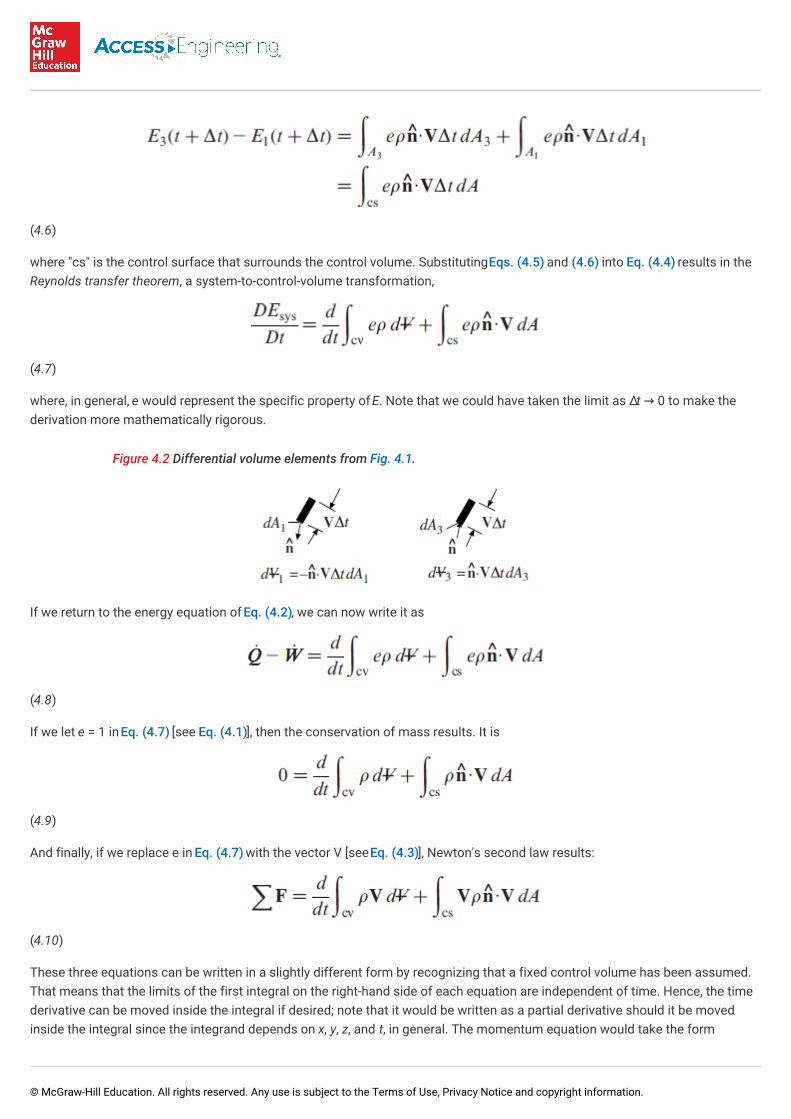
Figure 4.2 Differential volume elements from Fig. 4.1.
If we return to the energy equation of Eq. (4.2), we can now write it as
(4.8)
If we let e = 1 in Eq. (4.7) [see Eq. (4.1)], then the conservation of mass results. It is
(4.9)
And finally, if we replace e in Eq. (4.7) with the vector V [see Eq. (4.3)], Newton's second law results:
(4.10)
These three equations can be written in a slightly different form by recognizing that a fixed control volume has been assumed.That means that the limits of the first integral on the right-hand side of each equation are independent of time. Hence, the timederivative can be moved inside the integral if desired; note that it would be written as a partial derivative should it be movedinside the integral since the integrand depends on x, y, z, and t, in general. The momentum equation would take the form
© McGraw-Hill Education. All rights reserved. Any use is subject to the Terms of Use, Privacy Notice and copyright information.
(4.11)
The following three sections will apply these integral forms of the basic laws to problems in which the integrands are given orin which they can be assumed.
4.3. CONSERVATION OF MASS
The most general relationship for the conservation of mass using the Eulerian description that focuses on a fixed volume wasdeveloped in Sec. 4.2 and is
(4.12)
Since the limits on the volume integral do not depend on time, this can be written as
(4.13)
If the flow of interest can be assumed to be a steady flow so that time does not enter Eq. (4.13), the equation simplifies to
(4.14)
Those flows in which the density ρ is uniform over an area are of particular interest in our study of fluids. Also, mostapplications have one entrance and one exit. For such a problem, Eq. (4.14) can then be written as
(4.15)
where an overbar denotes an average over an area, i.e., . Note also that at an entrance, we use
since the unit vector points out of the volume and the velocity is into the volume, but at an exit
since the two vectors are in the same direction. We usually ignore the bar.
For incompressible flows in which the density does not change between the entrance and the exit and the velocity is uniformover each area, the conservation of mass takes the simplified form:
(4.16)
We refer to each of the above equations as the continuity equation. The one in Eq. (4.16) will be used quite often. Theseequations are used most often to relate the velocities between sections.
[1]
© McGraw-Hill Education. All rights reserved. Any use is subject to the Terms of Use, Privacy Notice and copyright information.
The quantity ρVA is the mass flux and has units of kg/s (slugs per second). The quantity VA is the flow rate (or discharge) andhas units of m /s (ft /sec or cfs). The mass flux is usually used in a gas flow and the discharge in a liquid flow. They aredefined by
(4.17)
where V is the average velocity at a section of the flow.
EXAMPLE 4.1 Water flows in a 6-cm-diameter pipe with a flow rate of 0.02 m /s. The pipe is reduced in diameter to 2.8 cm. Calculate themaximum velocity in the pipe. Also calculate the mass flux. Assume uniform velocity profiles.
Solution: The maximum velocity in the pipe will be where the diameter is the smallest. In the 2.8-cm-diameter section we have
The mass flux is
EXAMPLE 4.2 Water flows into a volume that contains a sponge with a flow rate of 0.02 m /s. It exits the volume through two tubes, one 2 cm indiameter and the other with a mass flux of 10 kg/s. If the velocity out the 2-cm-diameter tube is 15 m/s, determine the rate at which the mass ischanging inside the volume.
Solution: The continuity equation (4.12) is used. It is written in the form
where and the two exits and entrance account for the other three terms. Expressing the derivative term as ṁ the continuityequation becomes
The sponge is soaking up water at the rate of 5.29 kg/s.
4.4. THE ENERGY EQUATION
The first law of thermodynamics, or simply, the energy equation, is of use whenever heat transfer or work is desired. If there isessentially no heat transfer and no external work from a pump or some other device, the energy equation allows us to relate thepressure, the velocity, and the elevation. Let us see how this develops. We begin with the energy equation (4.8) in its generalform
(4.18)
3 3
3
3
vol
© McGraw-Hill Education. All rights reserved. Any use is subject to the Terms of Use, Privacy Notice and copyright information.
Most applications allow us to simplify this equation by assuming a steady, uniform flow with one entrance and one exit. Theenergy equation simplifies to
(4.19)
where we have used at the entrance. Using the continuity equation (4.15), this is written as
(4.20)
The work rate term results from a force moving with a velocity: . The force can be a pressure or a shear multipliedby an area. If the flow is in a conduit, e.g., a pipe or a channel, the walls do not move so there is no work done by the walls. Ifthere is a moving belt, there could be an input of work due to the shear between the belt and the fluid. The most common workrate terms result from the pressure forces at the entrance and the exit (pressure is assumed to be uniform over each area) andfrom shaft work rate in any device between the entrance and the exit. The work rate term is expressed as
(4.21)
where power output is considered positive and is the shaft power output from the control volume (a pump would be a
negative power and a turbine would provide a positive power output). Using the expression for e given in Eq. (1.33), Eq. (4.20)takes the form
(4.22)
The heat-transfer term and the internal energy terms form the losses in the flow (viscous effects result in heat transfer and/oran increase in internal energy). Divide Eq. (4.22) by mg and simplify
(4.23)
where we have included the loss term as h , called the head loss; it is . An incompressible
flow occurs in many applications so that γ = γ . Recall that γ for water is 9810 N/m (62.4 lb/ft ).
The head loss term is often expressed in terms of a loss coefficient K
(4.24)
where V is some characteristic velocity in the flow; if it is not obvious it will be specified. Some loss coefficients are listed inTable 7.2; in this chapter they will be given.
[2]
L
1 23 3
2
© McGraw-Hill Education. All rights reserved. Any use is subject to the Terms of Use, Privacy Notice and copyright information.
The term h is called the head loss because it has the dimension of length. We also refer to V /2g as the velocity head, p/γ asthe pressure head, and z as the head. The sum of these three terms is the total head.
The shaft-work term in Eq. (4.23) is usually due to either a pump or a turbine. If it is a pump, we can define the pump head H as
(4.25)
where is the power input to the pump and η is the pump efficiency. For a turbine the turbine head H is
(4.26)
where is the power output of the turbine and η is the turbine efficiency. Power has units of watts [(ft-lb)/sec] or
horsepower.
If the flow is not uniform over the entrance and the exit, an integration must be performed to obtain the kinetic energy. The rateat which the kinetic energy crosses an area is [see Eqs. (4.18) and (1.33)]
(4.27)
If the velocity distribution is known, the integration can be performed. A kinetic-energy correction factor α a is defined as
(4.28)
The kinetic energy term can then be written as
(4.29)
so that, for non-uniform flows, the energy equation takes the form
(4.30)
where and are the average velocities at sections 1 and 2, respectively. Equation (4.30) is used if the α's are known; forparabolic profiles, α = 2 in a pipe and α = 1.5 between parallel plates. For turbulent flows (most flows in engineeringapplications), α ≅ 1.
L2
P
P T
T
1 2
© McGraw-Hill Education. All rights reserved. Any use is subject to the Terms of Use, Privacy Notice and copyright information.
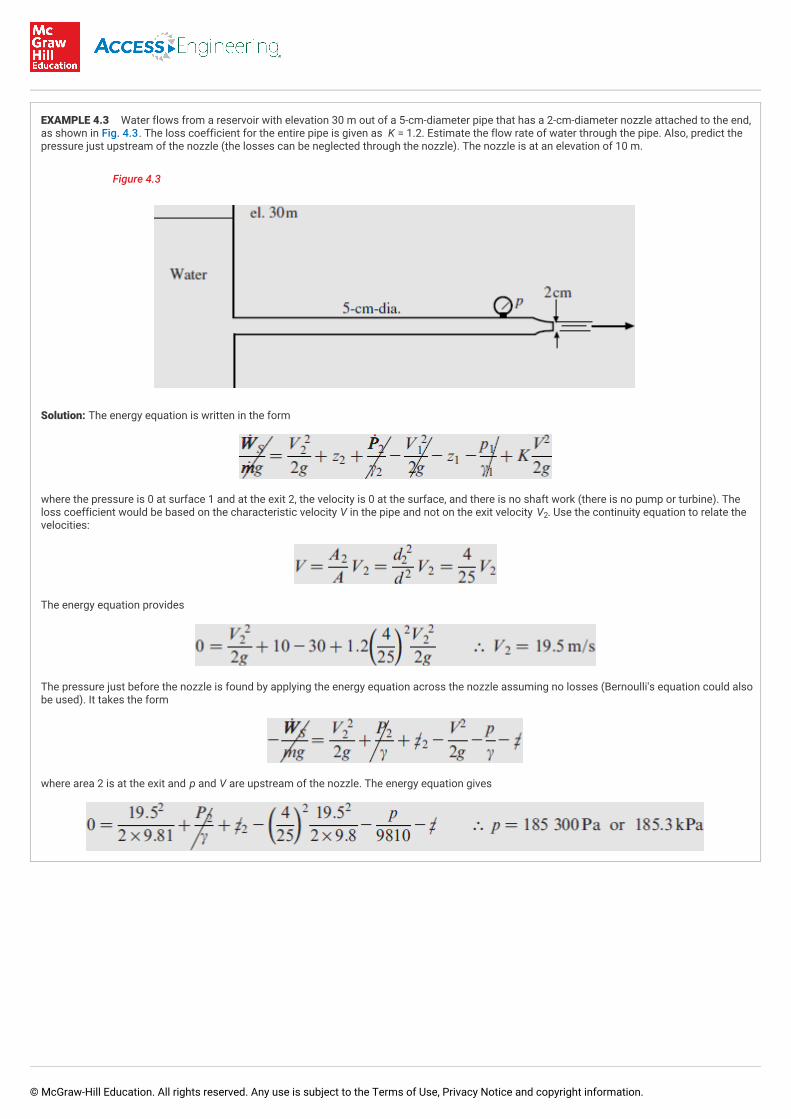
EXAMPLE 4.3 Water flows from a reservoir with elevation 30 m out of a 5-cm-diameter pipe that has a 2-cm-diameter nozzle attached to the end,as shown in Fig. 4.3. The loss coefficient for the entire pipe is given as K = 1.2. Estimate the flow rate of water through the pipe. Also, predict thepressure just upstream of the nozzle (the losses can be neglected through the nozzle). The nozzle is at an elevation of 10 m.
Figure 4.3
Solution: The energy equation is written in the form
where the pressure is 0 at surface 1 and at the exit 2, the velocity is 0 at the surface, and there is no shaft work (there is no pump or turbine). Theloss coefficient would be based on the characteristic velocity V in the pipe and not on the exit velocity V . Use the continuity equation to relate thevelocities:
The energy equation provides
The pressure just before the nozzle is found by applying the energy equation across the nozzle assuming no losses (Bernoulli's equation could alsobe used). It takes the form
where area 2 is at the exit and p and V are upstream of the nozzle. The energy equation gives
2
© McGraw-Hill Education. All rights reserved. Any use is subject to the Terms of Use, Privacy Notice and copyright information.
EXAMPLE 4.4 An energy conscious couple decides to dam up the creek flowing next to their cabin and estimates that a head of 4 m can beestablished above the exit to a turbine they bought on eBay. The creek is estimated to have a flow rate of 0.8 m /s. What is the maximum poweroutput of the turbine assuming no losses and a velocity at the turbine's exit of 3.6 m/s?
Solution: The energy equation is applied as follows:
It is only the head of the water above the turbine that provides the power; the exiting velocity subtracts from the power. There results, using ṁ =pQ = 1000 × 0.8 = 800kg/s,
Let us demonstrate that the units on ṁgz are J/s. The units on ṁgz are where, from F
= ma, we see that N = kg⋅m/s . If the proper units are included on the items in our equations, the units will come out as expected, i.e., the units on must be J/s.
4.5. THE MOMENTUM EQUATION
When a force in involved in a calculation, it is often necessary to apply Newton's second law, or simply, the momentumequation, to the problem of interest. For some general volume, using the Eulerian description of motion, the momentumequation was presented in Eq. (4.10) in its most general form for a fixed control volume as
(4.31)
When applying this equation to a control volume, we must be careful to include all forces acting on the control volume, so it isvery important to sketch the control volume and place the forces on the sketched control volume. (The control volume takes theplace of the free-body diagram utilized in courses in statics, dynamics, and solids.)
Most often, steady, uniform flows with one entrance and one outlet are encountered. For such flows, Eq. (4.31) reduces to
(4.32)
Using continuity ṁ = ρ A V = ρ A V , the momentum equation takes the simplified form
(4.33)
This is the form most often used when a force is involved in a calculation. It is a vector equation that contains the three scalarequations in a rectangular coordinate system
3
x 1
2
2 2 2 1 1 1
© McGraw-Hill Education. All rights reserved. Any use is subject to the Terms of Use, Privacy Notice and copyright information.
(4.34)
If the profiles at the entrance and exit are not uniform, Eq. (4.31) must be used and the integration performed or, if themomentum-correction factor β is known, it can be used. It is found from
(4.35)
The momentum equation for a steady flow with one entrance and one outlet then takes the form
(4.36)
where V and V represent the average velocity vectors over the two areas.
For parabolic profiles, β = 1.33 for a pipe and β = 1.2 for parallel plates. For turbulent flows (most flows in engineeringapplications), β ≅ 1.
An important application of the momentum equation is to the deflectors (or vanes) of pumps, turbines, or compressors. Theapplications involve both stationary defectors and moving deflectors. The following assumptions are made for both:
The frictional force between the fluid and the deflector is negligible.
The pressure is assumed to be constant as the fluid moves over the deflector.
The body force is assumed to be negligible.
The effect of the lateral spreading of the fluid stream is neglected.
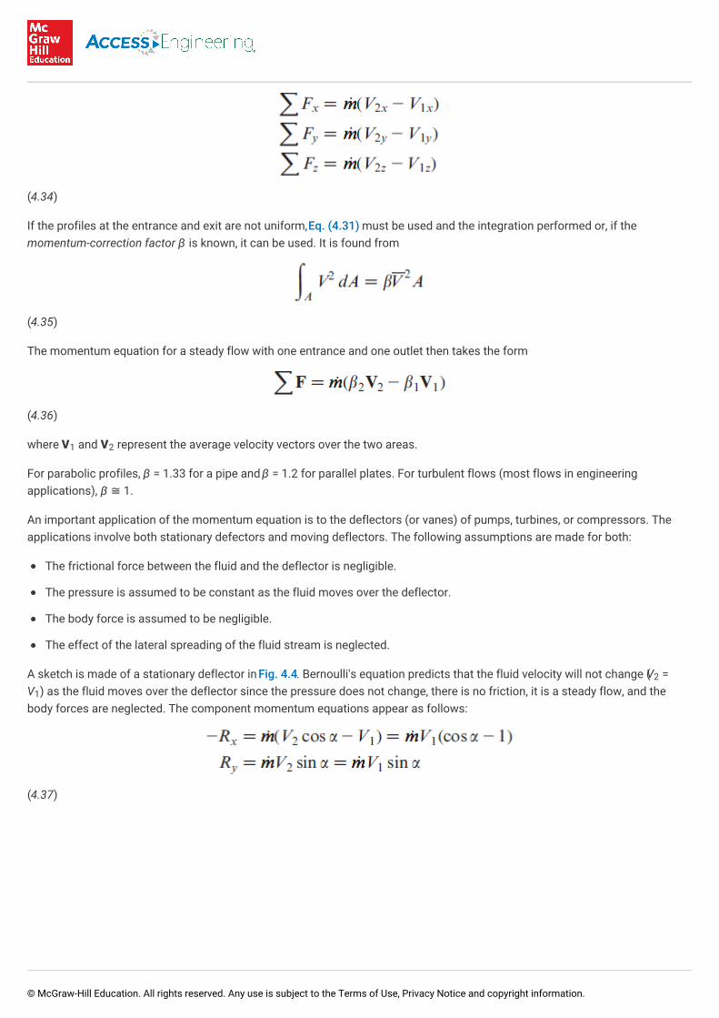
A sketch is made of a stationary deflector in Fig. 4.4. Bernoulli's equation predicts that the fluid velocity will not change (V =V ) as the fluid moves over the deflector since the pressure does not change, there is no friction, it is a steady flow, and thebody forces are neglected. The component momentum equations appear as follows:
(4.37)
1 2
2
1
© McGraw-Hill Education. All rights reserved. Any use is subject to the Terms of Use, Privacy Notice and copyright information.
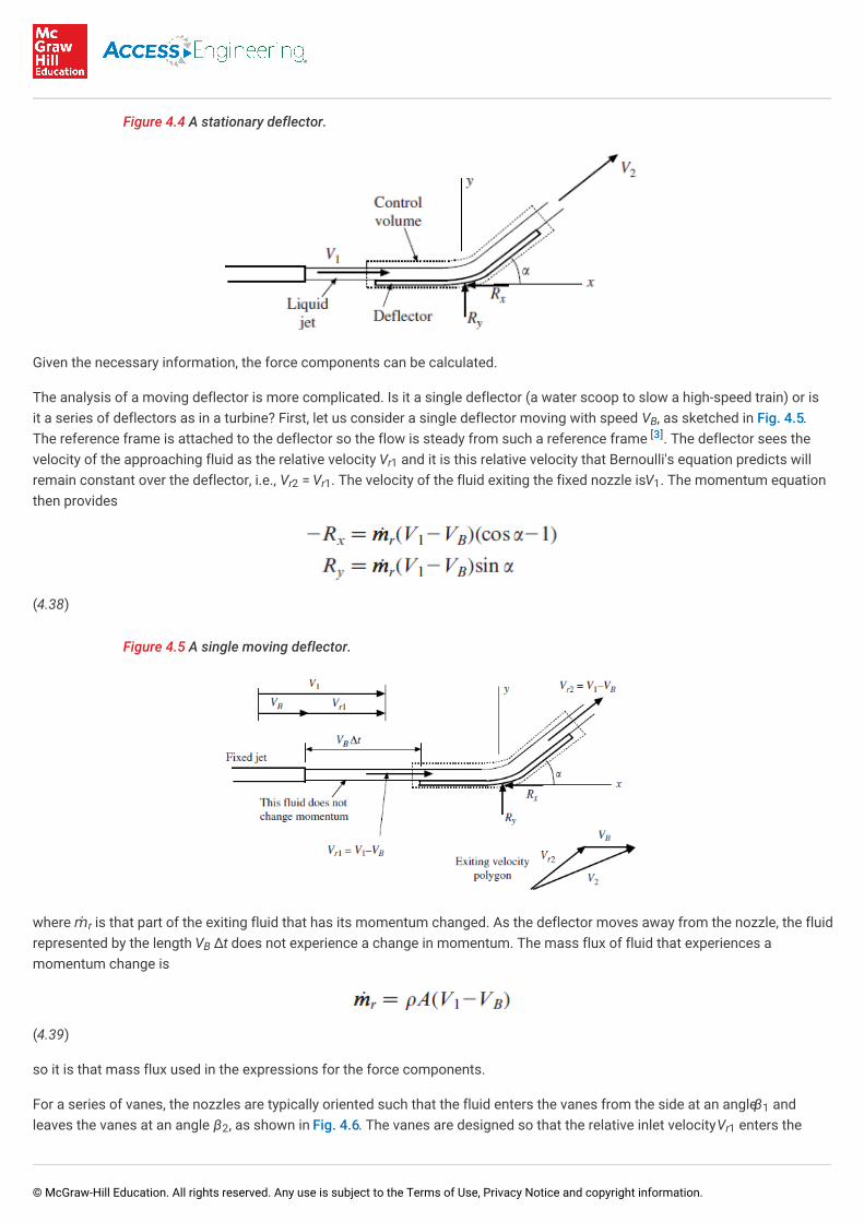
Figure 4.4 A stationary deflector.
Given the necessary information, the force components can be calculated.
The analysis of a moving deflector is more complicated. Is it a single deflector (a water scoop to slow a high-speed train) or isit a series of deflectors as in a turbine? First, let us consider a single deflector moving with speed V , as sketched in Fig. 4.5.The reference frame is attached to the deflector so the flow is steady from such a reference frame . The deflector sees thevelocity of the approaching fluid as the relative velocity V and it is this relative velocity that Bernoulli's equation predicts willremain constant over the deflector, i.e., V = V . The velocity of the fluid exiting the fixed nozzle is V . The momentum equationthen provides
(4.38)
Figure 4.5 A single moving deflector.
where ṁ is that part of the exiting fluid that has its momentum changed. As the deflector moves away from the nozzle, the fluidrepresented by the length V Δt does not experience a change in momentum. The mass flux of fluid that experiences amomentum change is
(4.39)
so it is that mass flux used in the expressions for the force components.
For a series of vanes, the nozzles are typically oriented such that the fluid enters the vanes from the side at an angle β andleaves the vanes at an angle β , as shown in Fig. 4.6. The vanes are designed so that the relative inlet velocity V enters the
B[3]
r1
r2 r1 1
r
B
1
2 r1
© McGraw-Hill Education. All rights reserved. Any use is subject to the Terms of Use, Privacy Notice and copyright information.
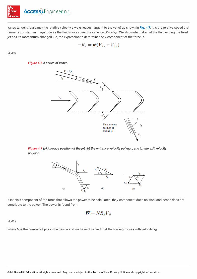
vanes tangent to a vane (the relative velocity always leaves tangent to the vane) as shown in Fig. 4.7. It is the relative speed thatremains constant in magnitude as the fluid moves over the vane, i.e., V = V . We also note that all of the fluid exiting the fixedjet has its momentum changed. So, the expression to determine the x-component of the force is
(4.40)
Figure 4.6 A series of vanes.
Figure 4.7 (a) Average position of the jet, (b) the entrance velocity polygon, and (c) the exit velocitypolygon.
It is this x-component of the force that allows the power to be calculated; the y-component does no work and hence does notcontribute to the power. The power is found from
(4.41)
where N is the number of jets in the device and we have observed that the force R moves with velocity V .
r2 r1
x B
© McGraw-Hill Education. All rights reserved. Any use is subject to the Terms of Use, Privacy Notice and copyright information.
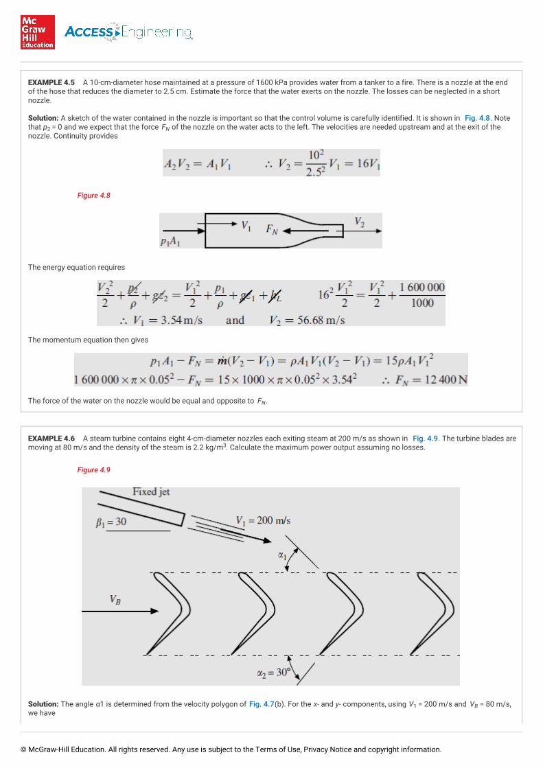
EXAMPLE 4.5 A 10-cm-diameter hose maintained at a pressure of 1600 kPa provides water from a tanker to a fire. There is a nozzle at the endof the hose that reduces the diameter to 2.5 cm. Estimate the force that the water exerts on the nozzle. The losses can be neglected in a shortnozzle.
Solution: A sketch of the water contained in the nozzle is important so that the control volume is carefully identified. It is shown in Fig. 4.8. Notethat p = 0 and we expect that the force F of the nozzle on the water acts to the left. The velocities are needed upstream and at the exit of thenozzle. Continuity provides
Figure 4.8
The energy equation requires
The momentum equation then gives
The force of the water on the nozzle would be equal and opposite to F .
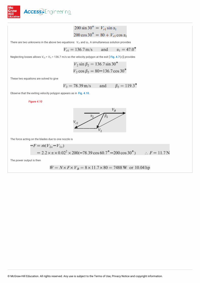
EXAMPLE 4.6 A steam turbine contains eight 4-cm-diameter nozzles each exiting steam at 200 m/s as shown in Fig. 4.9. The turbine blades aremoving at 80 m/s and the density of the steam is 2.2 kg/m . Calculate the maximum power output assuming no losses.
Figure 4.9
Solution: The angle α1 is determined from the velocity polygon of Fig. 4.7(b). For the x- and y- components, using V = 200 m/s and V = 80 m/s,we have
2 N
N
3
1 B
© McGraw-Hill Education. All rights reserved. Any use is subject to the Terms of Use, Privacy Notice and copyright information.
There are two unknowns in the above two equations: V and α . A simultaneous solution provides
Neglecting losses allows V = V = 136.7 m/s so the velocity polygon at the exit [ Fig. 4.7(c)] provides
These two equations are solved to give
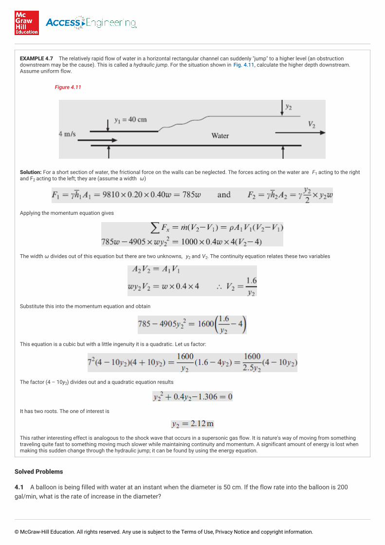
Observe that the exiting velocity polygon appears as in Fig. 4.10.
Figure 4.10
The force acting on the blades due to one nozzle is
The power output is then
r1 1
r2 rl
© McGraw-Hill Education. All rights reserved. Any use is subject to the Terms of Use, Privacy Notice and copyright information.
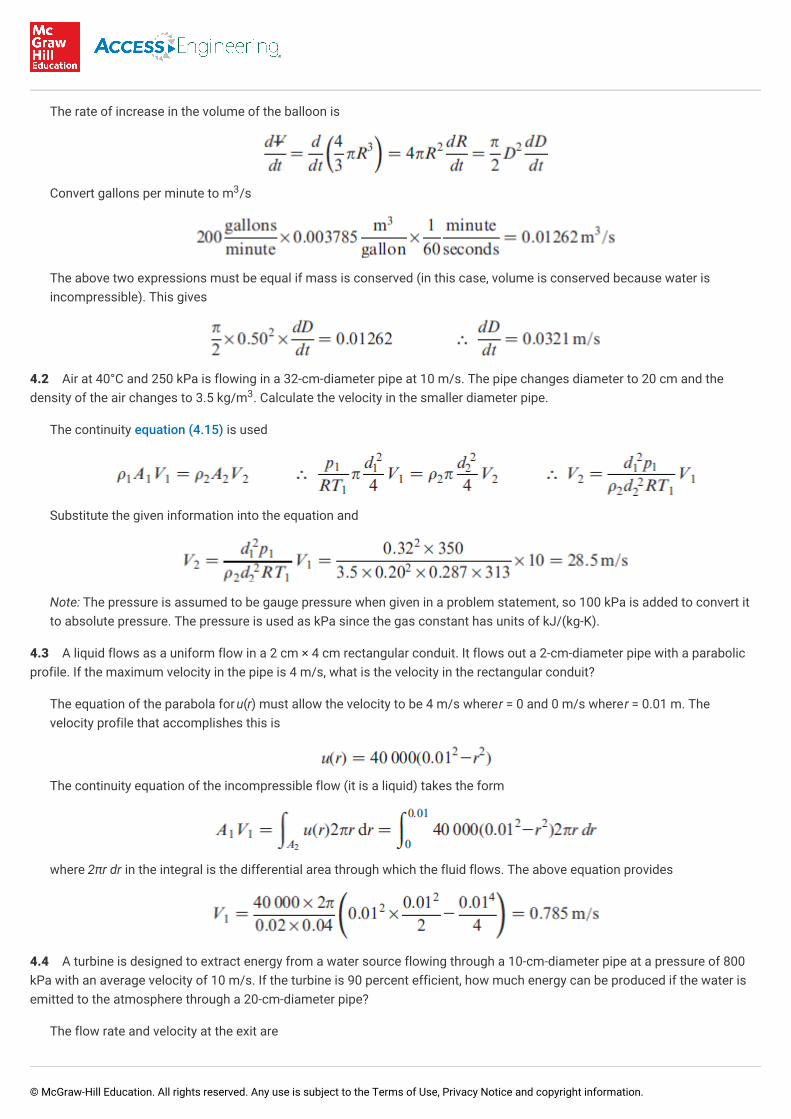
EXAMPLE 4.7 The relatively rapid flow of water in a horizontal rectangular channel can suddenly "jump" to a higher level (an obstructiondownstream may be the cause). This is called a hydraulic jump. For the situation shown in Fig. 4.11, calculate the higher depth downstream.Assume uniform flow.
Figure 4.11
Solution: For a short section of water, the frictional force on the walls can be neglected. The forces acting on the water are F acting to the rightand F acting to the left; they are (assume a width ω)
Applying the momentum equation gives
The width ω divides out of this equation but there are two unknowns, y and V . The continuity equation relates these two variables
Substitute this into the momentum equation and obtain
This equation is a cubic but with a little ingenuity it is a quadratic. Let us factor:
The factor (4 – 10y ) divides out and a quadratic equation results
It has two roots. The one of interest is
This rather interesting effect is analogous to the shock wave that occurs in a supersonic gas flow. It is nature's way of moving from somethingtraveling quite fast to something moving much slower while maintaining continuity and momentum. A significant amount of energy is lost whenmaking this sudden change through the hydraulic jump; it can be found by using the energy equation.
Solved Problems
4.1 A balloon is being filled with water at an instant when the diameter is 50 cm. If the flow rate into the balloon is 200gal/min, what is the rate of increase in the diameter?
12
2 2
2
© McGraw-Hill Education. All rights reserved. Any use is subject to the Terms of Use, Privacy Notice and copyright information.
The rate of increase in the volume of the balloon is
Convert gallons per minute to m /s
The above two expressions must be equal if mass is conserved (in this case, volume is conserved because water isincompressible). This gives
4.2 Air at 40°C and 250 kPa is flowing in a 32-cm-diameter pipe at 10 m/s. The pipe changes diameter to 20 cm and thedensity of the air changes to 3.5 kg/m . Calculate the velocity in the smaller diameter pipe.
The continuity equation (4.15) is used
Substitute the given information into the equation and
Note: The pressure is assumed to be gauge pressure when given in a problem statement, so 100 kPa is added to convert itto absolute pressure. The pressure is used as kPa since the gas constant has units of kJ/(kg-K).
4.3 A liquid flows as a uniform flow in a 2 cm × 4 cm rectangular conduit. It flows out a 2-cm-diameter pipe with a parabolicprofile. If the maximum velocity in the pipe is 4 m/s, what is the velocity in the rectangular conduit?
The equation of the parabola for u(r) must allow the velocity to be 4 m/s where r = 0 and 0 m/s where r = 0.01 m. Thevelocity profile that accomplishes this is
The continuity equation of the incompressible flow (it is a liquid) takes the form
where 2πr dr in the integral is the differential area through which the fluid flows. The above equation provides
4.4 A turbine is designed to extract energy from a water source flowing through a 10-cm-diameter pipe at a pressure of 800kPa with an average velocity of 10 m/s. If the turbine is 90 percent efficient, how much energy can be produced if the water isemitted to the atmosphere through a 20-cm-diameter pipe?
The flow rate and velocity at the exit are
3
3
© McGraw-Hill Education. All rights reserved. Any use is subject to the Terms of Use, Privacy Notice and copyright information.
The pressure at the outlet is assumed to be atmospheric, i.e., p = 0. The energy equation is applied between the inlet andthe exit of the turbine
where the head loss term is omitted and included as an efficiency of the turbine. Substituting the appropriate informationgives
This is the power extracted from the water. The power produced would be less than this due to the losses through theturbine measured by the efficiency, i.e.
Check the units on the above equations to make sure they are consistent.
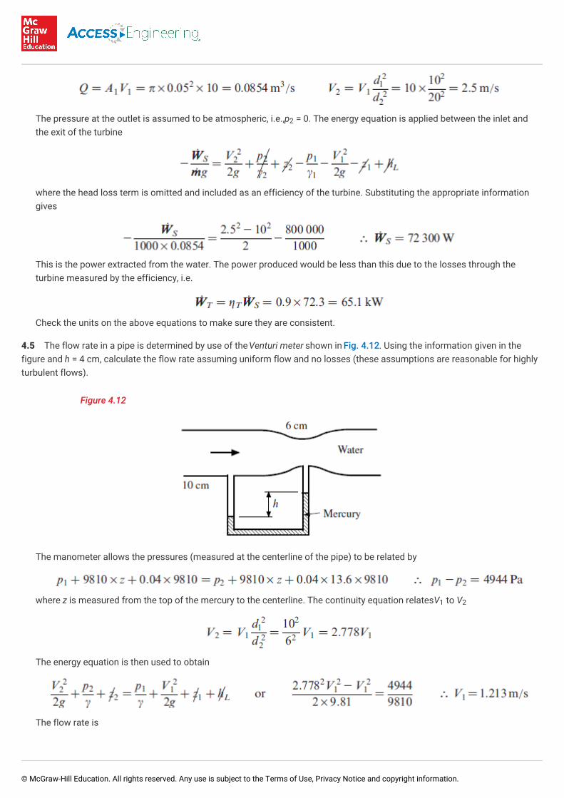
4.5 The flow rate in a pipe is determined by use of the Venturi meter shown in Fig. 4.12. Using the information given in thefigure and h = 4 cm, calculate the flow rate assuming uniform flow and no losses (these assumptions are reasonable for highlyturbulent flows).
Figure 4.12
The manometer allows the pressures (measured at the centerline of the pipe) to be related by
where z is measured from the top of the mercury to the centerline. The continuity equation relates V to V
The energy equation is then used to obtain
The flow rate is
2
1 2
© McGraw-Hill Education. All rights reserved. Any use is subject to the Terms of Use, Privacy Notice and copyright information.
4.6 A dam is proposed on a remote stream that measures approximately 25-cm deep by 350-cm wide with an average velocityof 2.2 m/s. If the dam can be constructed so that the free surface above a turbine is 10 m, estimate the maximum power outputof an 88 percent efficient turbine.
The flow rate of the water passing through the turbine is
The energy equation is applied between the surface of the reservoir behind the dam, where p = 0, V = 0, and z = 10 m andthe outlet of the turbine where we assume, for maximum power output, that V ≅ 0, p ≅ 0, and z = 0
or
The turbine losses are included by the use of the efficiency. The maximum turbine output is
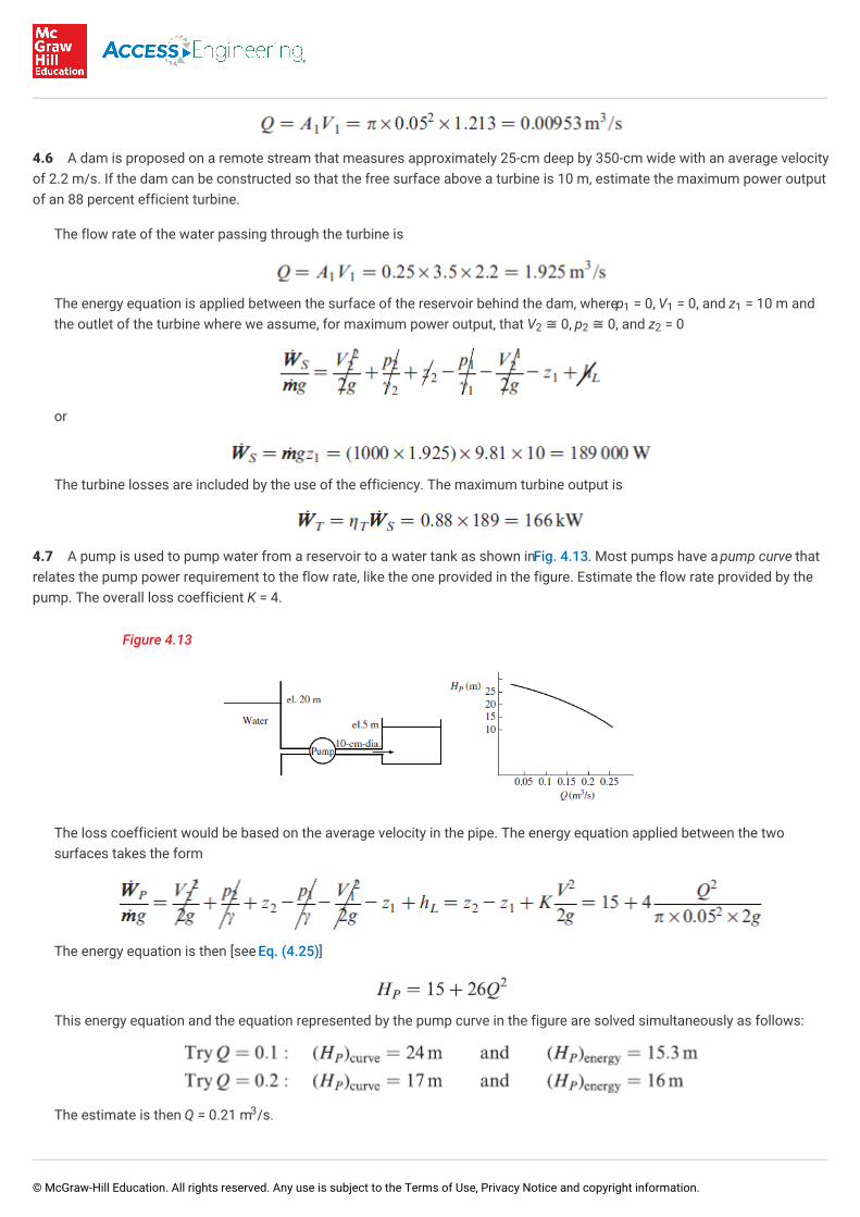
4.7 A pump is used to pump water from a reservoir to a water tank as shown in Fig. 4.13. Most pumps have a pump curve thatrelates the pump power requirement to the flow rate, like the one provided in the figure. Estimate the flow rate provided by thepump. The overall loss coefficient K = 4.
Figure 4.13
The loss coefficient would be based on the average velocity in the pipe. The energy equation applied between the twosurfaces takes the form
The energy equation is then [see Eq. (4.25)]
This energy equation and the equation represented by the pump curve in the figure are solved simultaneously as follows:
The estimate is then Q = 0.21 m /s.
1 1 1
2 2 2
3
© McGraw-Hill Education. All rights reserved. Any use is subject to the Terms of Use, Privacy Notice and copyright information.
4.8 Integrate the appropriate velocity profile and calculate the kinetic energy transported by a flow of water that has aparabolic profile in a 4-cm-diameter pipe if the flow rate is 0.005 m /s.
The parabolic profile that has u = 0 at the wall where r = 0.02 m and u = u at the centerline is u(r) = u (1–r /0.02 ). Theflow rate is
The rate of differential kinetic energy that passes through the differential area 2πr dr is . This
is integrated to yield
This can be checked using α = 2, as noted after Eq. (4.30)
where we have used the average velocity as half of the maximum velocity for a parabolic profile in a pipe.
4.9 A nozzle is attached to a 6-cm-diameter hose but the horizontal nozzle turns the water through an angle of 90°. The nozzleexit is 3 cm in diameter and the flow rate is 500 L/min. Determine the force components of the water on the nozzle and themagnitude of the resultant force. The pressure in the hose is 400 kPa and the water exits to the atmosphere.
First, the control volume should be sketched since it is not given in the problem statement. It appears as shown in Fig. 4.14.The control volume shows the water with the force components of the nozzle on the water. The velocities are calculated tobe
3
max max2 2
© McGraw-Hill Education. All rights reserved. Any use is subject to the Terms of Use, Privacy Notice and copyright information.
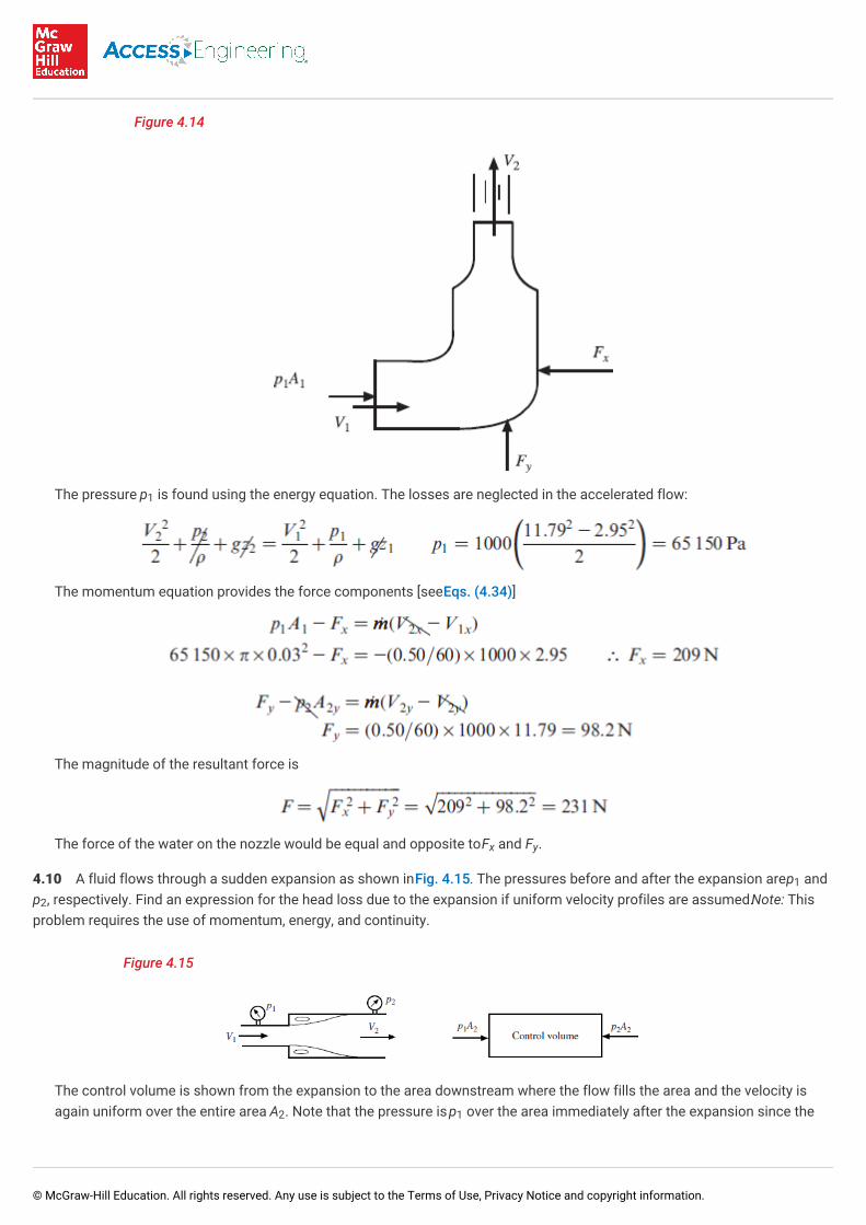
Figure 4.14
The pressure p is found using the energy equation. The losses are neglected in the accelerated flow:
The momentum equation provides the force components [see Eqs. (4.34)]
The magnitude of the resultant force is
The force of the water on the nozzle would be equal and opposite to F and F .
4.10 A fluid flows through a sudden expansion as shown in Fig. 4.15. The pressures before and after the expansion are p andp , respectively. Find an expression for the head loss due to the expansion if uniform velocity profiles are assumed. Note: Thisproblem requires the use of momentum, energy, and continuity.
Figure 4.15
The control volume is shown from the expansion to the area downstream where the flow fills the area and the velocity isagain uniform over the entire area A . Note that the pressure is p over the area immediately after the expansion since the
1
x y
1
2
2 1
© McGraw-Hill Education. All rights reserved. Any use is subject to the Terms of Use, Privacy Notice and copyright information.
flow separates with parallel streamlines and then expands to fill the area. (The head loss is due to the energy needed tosustain the flow in the separated region.) The momentum equation provides
The energy equation that introduces the head loss h , applied between sections 1 and 2, is
Substituting the pressure difference from the momentum equation gives
The continuity equation requires V = V A /A . Substitute this into the above equation and obtain the expression for thehead loss
The loss coefficient of Eq. (4.24) is K = (1–A /A ) based on the inlet velocity V .
4.11 The blade on a snowplow turns the wet snow through an angle of 120° but off to one side at 30°. If the snow has adensity of 500 kg/m , what power is needed to move the blade at 40 mi/h if it scoops snow that is 15-cm deep and 3-m wide?
The momentum equation (4.37) is written to account for the component due to the side angle (the blade is stationary andthe snow moves toward the blade)
where 0.447 converts mi/h to m/s. We have neglected the friction generated by the snow moving over the blade, whichwould be small compared to the above force, so that the speed of the snow relative to the blade remains constant, i.e., V ≅V . The power is then
Supplementary Problems
4.12 What assumptions are needed on a flow to allow Eq. (4.3) to be simplified to ΣF = ma.
4.13 Sketch the three volumes shown generally in Fig. 4.1, assuming a short time-increment Δt for thefixed control volume of
(a) A nozzle on the end of a hose.
(b) A balloon into which air is entering (the fixed volume is the balloon at time t).
(c) A balloon from which air is exiting (the fixed volume is the balloon at time t).
(d) A Tee in a pipe line.
4.14 Sketch the velocity vector V and the normal unit vector on each area.
(a) The free surface area of a water tank that is being drained.
L
2 1 1 2
1 22
1
3
2
1
© McGraw-Hill Education. All rights reserved. Any use is subject to the Terms of Use, Privacy Notice and copyright information.
(b) The inlet area of a turbine.
(c) The wall of a pipe.
(d) The bottom of a canal.
(e) The inlet area to a cylindrical screen around a drain.
4.15 A rectangle surrounds a two-dimensional, stationary airfoil. It is at a distance from the airfoil on all sides. Sketch the boxcontaining the airfoil along with the velocity vector V and the normal unit vector on all four sides of the rectangle.
4.16 We used
in the derivation of the system-to-control-volume transformation. What constraint allows this equivalence? Why is it anordinary derivative on the left but a partial derivative on the right?
Conservation of Mass
4.17 Apply Eq. (4.14) to a flow in a pipe that divides into two exiting areas with different densities at each area assuminguniform flows over all three areas.
4.18 Water flows in a 4-cm-diameter pipe at 20 m/s. The pipe enlarges to a diameter of 6 cm. Calculate the flow rate, themass flux, and the velocity in the larger diameter section of pipe.
4.19 Water flows at a depth of 40 cm in a 100-cm-diameter storm sewer. Calculate the flow rate and the mass flux if theaverage velocity is 3 m/s.
4.20 Air at 25°C and 240 kPa flows in a 10-cm-diameter pipe at 40 m/s. What are the flow rate and the mass flux in the pipe?(Recall that pressures are always gauge pressures unless stated otherwise.)
4.21 Air flows in a 20-cm-diameter duct at 120°C and 120 kPa with a mass flux of 5 kg/s. The circular duct converts to a 20-cm square duct in which the temperature and pressure are 140°C and 140 kPa, respectively. Determine the velocities in bothsections of the duct.
4.22 Air is exiting a 100-cm-diameter balloon out a 1-cm-diameter nozzle. If the pressure and temperature at the exit are 110kPa and 22°C, respectively, and the exit velocity is 30 m/s, calculate the flow rate, the mass flux, and the rate at which thediameter is changing.
4.23 Water flows in a 4-cm-diameter pipe at 20 m/s. The pipe divides into two pipes, one 2 cm in diameter and the other 3 cmin diameter. If 10 kg/s flows from the 2-cm-diameter pipe, calculate the flow rate from the 3-cm-diameter pipe.
4.24 Water flows in a 2-cm-diameter pipe at 10 m/s vertically upward to the center of two horizontal circular disks separatedby 8 mm. It flows out between the disks at a radius of 25 cm. Sketch the pipe/disk arrangement. Calculate average velocity ofthe water leaving the disks. Also, calculate the average velocity of the water between the disks at a position where the radius ofthe disks is 10 cm.
4.25 High-velocity air at 20°C and 100 kPa absolute flows in a conduit at 600 m/s. It undergoes a sudden change (a shockwave) to 263 m/s and 438°C with no change in conduit dimensions. Determine the mass flux and the downstream pressure ifthe conduit cross-sectional area is 500 cm .
4.26 Water flows in a 12-cm-diameter pipe with the velocity profiles shown in Fig. 4.16. The maximum velocity for each profileis 20 m/s. Calculate the mass flux, the flow rate, and the average velocity.
2
© McGraw-Hill Education. All rights reserved. Any use is subject to the Terms of Use, Privacy Notice and copyright information.
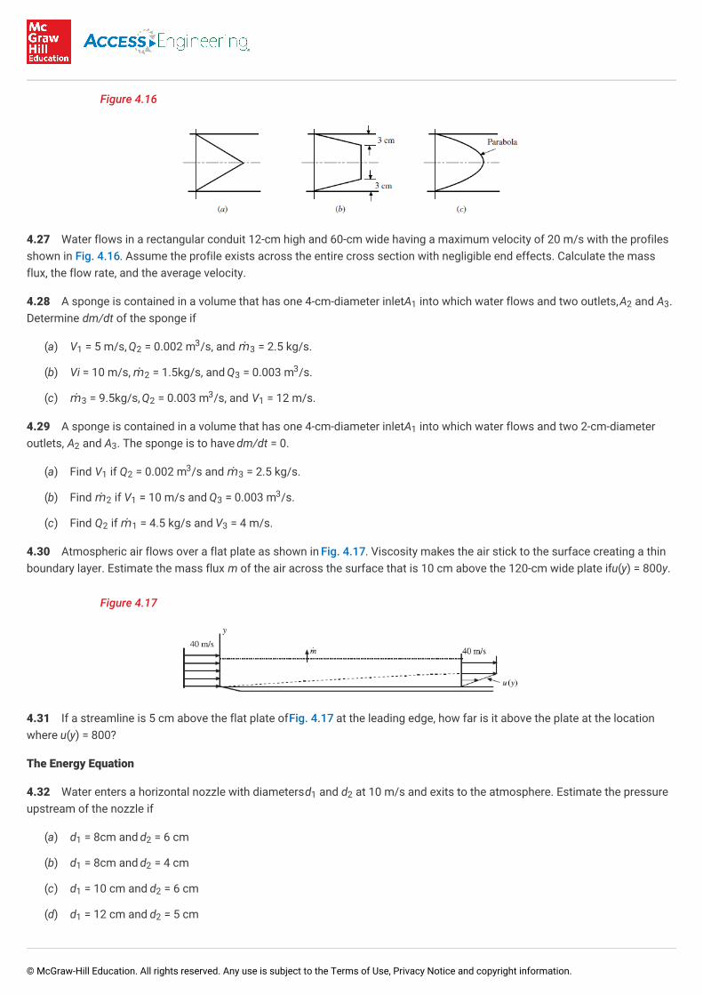
Figure 4.16
4.27 Water flows in a rectangular conduit 12-cm high and 60-cm wide having a maximum velocity of 20 m/s with the profilesshown in Fig. 4.16. Assume the profile exists across the entire cross section with negligible end effects. Calculate the massflux, the flow rate, and the average velocity.
4.28 A sponge is contained in a volume that has one 4-cm-diameter inlet A into which water flows and two outlets, A and A .Determine dm/dt of the sponge if
(a) V = 5 m/s, Q = 0.002 m /s, and ṁ = 2.5 kg/s.
(b) Vi = 10 m/s, ṁ = 1.5kg/s, and Q = 0.003 m /s.
(c) ṁ = 9.5kg/s, Q = 0.003 m /s, and V = 12 m/s.
4.29 A sponge is contained in a volume that has one 4-cm-diameter inlet A into which water flows and two 2-cm-diameteroutlets, A and A . The sponge is to have dm/dt = 0.
(a) Find V if Q = 0.002 m /s and ṁ = 2.5 kg/s.
(b) Find ṁ if V = 10 m/s and Q = 0.003 m /s.
(c) Find Q if ṁ = 4.5 kg/s and V = 4 m/s.
4.30 Atmospheric air flows over a flat plate as shown in Fig. 4.17. Viscosity makes the air stick to the surface creating a thinboundary layer. Estimate the mass flux m of the air across the surface that is 10 cm above the 120-cm wide plate if u(y) = 800y.
Figure 4.17
4.31 If a streamline is 5 cm above the flat plate of Fig. 4.17 at the leading edge, how far is it above the plate at the locationwhere u(y) = 800?
The Energy Equation
4.32 Water enters a horizontal nozzle with diameters d and d at 10 m/s and exits to the atmosphere. Estimate the pressureupstream of the nozzle if
(a) d = 8cm and d = 6 cm
(b) d = 8cm and d = 4 cm
(c) d = 10 cm and d = 6 cm
(d) d = 12 cm and d = 5 cm
1 2 3
1 23
3
2 33
3 23
1
1
2 3
1 23
3
2 1 33
2 1 3
1 2
1 2
1 2
1 2
1 2
© McGraw-Hill Education. All rights reserved. Any use is subject to the Terms of Use, Privacy Notice and copyright information.
4.33 Water is contained in a large tower that supplies a city. If the top of the water is 30 m above an outlet at the base of thetower, what maximum velocity can be expected at the outlet (to the atmosphere)? How does this maximum velocity comparewith that of a rock dropped from the same height?
4.34 A high-speed jet is used to cut solid materials. Estimate the maximum pressure developed on the material if the velocityissuing from the water jet is (a)100 m/s, (b) 120 m/s, and (c) 150 m/s.
4.35 Rework Solved Problem 4.5 with (a) h = 5 cm, (b) h = 6 cm, and (c) h = 8 cm.
4.36 Integrate the appropriate velocity profile and calculate the rate of kinetic energy transported by a flow of water that has aparabolic profile in a channel that measures 2 cmx 15 cm if the flow rate is 0.012 m /s. Check your calculation using Eq. (4.30)with α = 1.5.
4.37 The loss coefficient in Example 4.3 is increased to (a)2.0, (b) 3.2, and (c) 6.0. Rework the problem. (The loss coefficientdepends primarily on the pipe material, such as plastic, copper, wrought iron, so it can vary markedly.)
4.38 Water is transported from one reservoir with surface elevation of 135 m to a lower reservoir with surface elevation of 25m through a 24-cm-diameter pipe. Estimate the flow rate and the mass flux through the pipe if the loss coefficient between thetwo surfaces is (a) 20, (b) 30, and (c) 40.
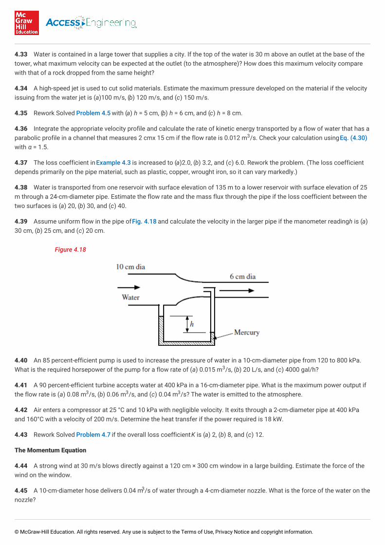
4.39 Assume uniform flow in the pipe of Fig. 4.18 and calculate the velocity in the larger pipe if the manometer reading h is (a)30 cm, (b) 25 cm, and (c) 20 cm.
Figure 4.18
4.40 An 85 percent-efficient pump is used to increase the pressure of water in a 10-cm-diameter pipe from 120 to 800 kPa.What is the required horsepower of the pump for a flow rate of (a) 0.015 m /s, (b) 20 L/s, and (c) 4000 gal/h?
4.41 A 90 percent-efficient turbine accepts water at 400 kPa in a 16-cm-diameter pipe. What is the maximum power output ifthe flow rate is (a) 0.08 m /s, (b) 0.06 m /s, and (c) 0.04 m /s? The water is emitted to the atmosphere.
4.42 Air enters a compressor at 25 °C and 10 kPa with negligible velocity. It exits through a 2-cm-diameter pipe at 400 kPaand 160°C with a velocity of 200 m/s. Determine the heat transfer if the power required is 18 kW.
4.43 Rework Solved Problem 4.7 if the overall loss coefficient K is (a) 2, (b) 8, and (c) 12.
The Momentum Equation
4.44 A strong wind at 30 m/s blows directly against a 120 cm × 300 cm window in a large building. Estimate the force of thewind on the window.
4.45 A 10-cm-diameter hose delivers 0.04 m /s of water through a 4-cm-diameter nozzle. What is the force of the water on thenozzle?
3
3
3 3 3
3
© McGraw-Hill Education. All rights reserved. Any use is subject to the Terms of Use, Privacy Notice and copyright information.
4.46 A 90°-nozzle with exit diameter d is attached to a hose of diameter 3d with pressure p. The nozzle changes the directionof the water flow from the hose through an angle of 90°. Calculate the magnitude of the force of the water on the nozzle if
(a) p = 200 kPa, d = 1 cm
(b) p = 400 kPa, d = 6 mm
(c) p = 300 kPa, d = 1.2 cm
(d) p = 500 kPa, d = 2.2 cm
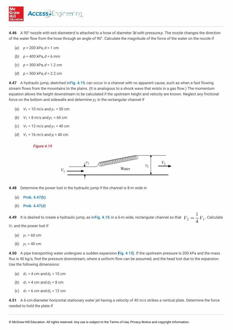
4.47 A hydraulic jump, sketched in Fig. 4.19, can occur in a channel with no apparent cause, such as when a fast flowingstream flows from the mountains to the plains. (It is analogous to a shock wave that exists in a gas flow.) The momentumequation allows the height downstream to be calculated if the upstream height and velocity are known. Neglect any frictionalforce on the bottom and sidewalls and determine y in the rectangular channel if
(a) V = 10 m/s and y = 50 cm
(b) V = 8 m/s and y = 60 cm
(c) V = 12 m/s and y = 40 cm
(d) V = 16 m/s and y = 40 cm
Figure 4.19
4.48 Determine the power lost in the hydraulic jump if the channel is 8-m wide in
(a) Prob. 4.47(b)
(b) Prob. 4.47(d)
4.49 It is desired to create a hydraulic jump, as in Fig. 4.19, in a 6-m wide, rectangular channel so that . Calculate
V and the power lost if
(a) y = 60 cm
(b) y = 40 cm
4.50 A pipe transporting water undergoes a sudden expansion (Fig. 4.15). If the upstream pressure is 200 kPa and the massflux is 40 kg/s, find the pressure downstream, where a uniform flow can be assumed, and the head lost due to the expansion.Use the following dimensions:
(a) d = 4 cm and d = 10 cm
(b) d = 4 cm and d = 8 cm
(c) d = 6 cm and d = 12 cm
4.51 A 6-cm-diameter horizontal stationary water jet having a velocity of 40 m/s strikes a vertical plate. Determine the forceneeded to hold the plate if
2
1 1
1 1
1 1
1 l
1
1
1
1 2
1 2
1 2
© McGraw-Hill Education. All rights reserved. Any use is subject to the Terms of Use, Privacy Notice and copyright information.
(a) it is stationary
(b) it moves away from the jet at 20 m/s
(c) it moves into the jet at 20 m/s
4.52 A 4-cm-diameter horizontal stationary water jet having a velocity of 50 m/s strikes a cone having an included angle at theapex of 60°. The water leaves the cone symmetrically. Determine the force needed to hold the cone if
(a) it is stationary
(b) it moves away from the jet at 20 m/s
(c) it moves into the jet at 20 m/s
4.53 A jet boat traveling at 12 m/s takes in 0.08 m /s of water and discharges it at 24 m/s faster than the boat's speed.Estimate the thrust produced and power required.
4.54 The deflector of Fig. 4.4 changes the direction of a 60 mm × 24 cm sheet of water with V = 30 m/s such that α = 60°.Calculate the force components of the water on the deflector if
(a) it is stationary
(b) it moves away from the jet at 20 m/s
(c) it moves into the jet at 20 m/s
4.55 The blades of Fig. 4.6 deflect 10, 2-cm-diameter jets of water each having V = 40 m/s. Determine the blade angle α andthe power output assuming no losses if
(a) β = 30°, α = 45°, and V = 20 m/s
(b) β = 20°, α = 50°, and V = 15 m/s
(c) β = 20°, α = 40°, and V = 20 m/s
(d) β = 40°, α = 35°, and V = 20 m/s
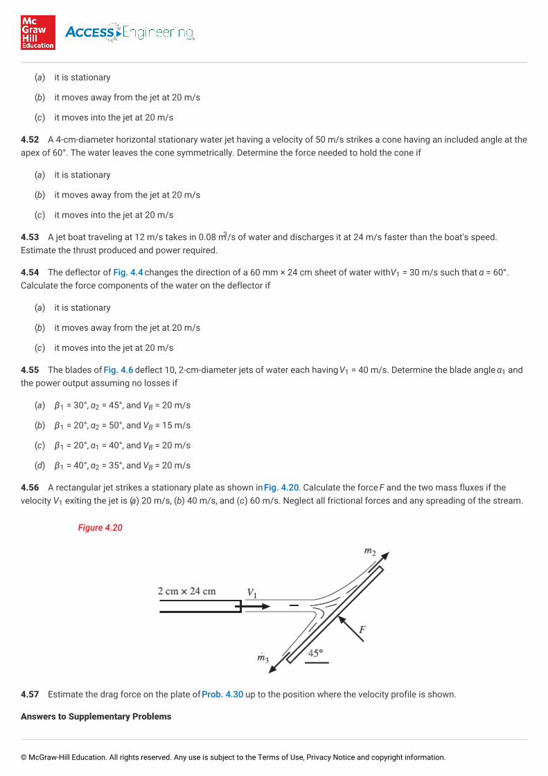
4.56 A rectangular jet strikes a stationary plate as shown in Fig. 4.20. Calculate the force F and the two mass fluxes if thevelocity V exiting the jet is (a) 20 m/s, (b) 40 m/s, and (c) 60 m/s. Neglect all frictional forces and any spreading of the stream.
Figure 4.20
4.57 Estimate the drag force on the plate of Prob. 4.30 up to the position where the velocity profile is shown.
Answers to Supplementary Problems
3
1
1 1
1 2 B
1 2 B
1 1 B
1 2 B
1
© McGraw-Hill Education. All rights reserved. Any use is subject to the Terms of Use, Privacy Notice and copyright information.
4.12 V = V(t), inertial ref frame
4.16 Fixed cv
4.17 ρ A V = ρ A V + ρ A V
4.18 0.0251 m /s, 25.1 kg/s, 8.89 m/s
4.19 1.182 m /s, 1182 kg/s
4.20 0.314 m /s, 1.25 kg/s
4.21 81.6 m/s, 61.7 m/s
4.22 0.236 m /s, 0.585 kg/s, 0.075 m/s
4.23 0.01513 m /s
4.24 0.25 m/s, 0.625 m/s
4.25 35.7 kg/s, 554 kPa
4.26 (a) 0.0754 m /s, 75.4 kg/s, 6.67 m/s (b) 0.1369 m /s, 1369 kg/s, 12.1 m/s (c) 0.1131 m /s, 1131 kg/s, 10 m/s
4.27 (a) 180 kg/s, 0.018 m /s, 10 m/s (b) 1080 kg/s, 1.08 m /s, 11.25 m/s (c) 960 kg/s, 0.096 m /s, 10 m/s
4.28 (a) 2.33 kg/s (b) 8.07 kg/s (c) 2.58 kg/s
4.29 (a) 3.58 m/s (b) 9.57 kg/s (c) 3.24 m /s
4.30 1.46 kg/s
4.31 52.5 mm
4.32 (a) 17.78 m/s, 108 kPa (b) 40 m/s, 750 kPa (c) 27 8 m/s, 336 kPa (d) 57.6 m/s, 1609 kPa
4.33 24.3 m/s, same
4.34 (a) 5000 kPa (b) 7200 kPa (c) 11 250 kPa
4.35 (a) 0.01065 m /s (b) 0.01167 m /s (c) 0.01348 m /s
4.36 144 J/s
4.37 (a) 181.9 kPa (b) 176.6 kPa (c) 165.7 kPa
4.38 (a) 0.470 m /s, 470 kg/s (b) 0.384 m /s, 384 kg/s (c) 0.332 m /s, 332 kg/s
4.39 (a) 8.58 m/s (b) 7.83 m/s (c) 7.00 m/s
4.40 (a) 16.1 hp (b) 21.4 hp (c) 4.51 hp
4.41 (a) 28.8 kW (b) 21.6 kW (c) 14.4 kW
4.42 – 3140 J/s
4.43 (a) 0.22 m /s (b) 0.20 m /s (c) 0.19 m /s
4.44 1980 N
1 11
2 2 2 3 3 3
3
3
3
3
3
3 3 3
3 3 3
3
3 3 3
3 3 3
3 3 3
© McGraw-Hill Education. All rights reserved. Any use is subject to the Terms of Use, Privacy Notice and copyright information.
4.45 2780 N
4.46 (a) 148N (b) 106.7N (c) 320N (d) 1795 N
4.47 (a) 2.95m (b) 2.51m (c) 3.23m (d) 4.37
4.48 (a) 439 kW (b) 1230 kW
4.49 (a) 7.67 m/s, 272 kW (b) 6.26 m/s, 99.5 kW
4.50 (a) 336 kPa, 36.4 m (b) 390 kPa, 29.2 m (c) 238 kPa, 5.73 m
4.51 (a) 4524N (b) 1131N (c) 10 180 N
4.52 (a) 421N (b) 151.5N (c) 825 N
4.53 30.9 hp
4.54 (a) 6480 N, 11 220N (b) 720 N, 1247N (c) 18 000 N, 31 200 N
4.55 (a) 53.79°, 108 hp (b) 31.2°, 100 hp (c) 37.87°, 17 hp (d) 67.5°, 113 hp
4.56 (a) 1358 N, 81.9 kg/s, 11.5 kg/s (b) 5430 N, 163.9 kg=/s, 22.9 kg/s (c) 12 220 N, 246 kg/s, 34.4 kg/s
4.57 9.9 N
Not all incompressible flows have constant density. Atmospheric and oceanic flows are examples as is salt water flowing in a canalwhere fresh water is also flowing.
We used m = P A V = P A V .
If the deflector is observed from the fixed jet, the deflector moves away from the jet and the flow is not a steady flow. It is steady if theflow is observed from the deflector.
[1]
[2] 2 2 2 1 1 1
[3]
© McGraw-Hill Education. All rights reserved. Any use is subject to the Terms of Use, Privacy Notice and copyright information.
Related Documents