© 2016 PLASTICON COMPOSITES ALL RIGHTS RESERVED White paper, published by Plasticon Composites: The installation of a corrosion resistant fiberglass chimney liner in a concrete chimney at the Turów (Poland) power plant. Case study: FRP chimneys and ducts, including by-pass system for Power Station Turów Written by J.W. Warnar, Commercial Director Year of publication: 2016 Plasticon Composites International Contracting BV Location: Hengelo, Overijssel, The Netherlands Keywords: Flue Gas Desulphurization, FRP, Chimney liner, Gas Duct, By-pass, 20-160 °C, Retrofit, Corrosion resistance, Coal Fire Power Plants

Welcome message from author
This document is posted to help you gain knowledge. Please leave a comment to let me know what you think about it! Share it to your friends and learn new things together.
Transcript
© 2016 PLASTICON COMPOSITES ALL RIGHTS RESERVED
White paper, published by Plasticon Composites:
The installation of a corrosion resistant
fiberglass chimney liner in a concrete chimney
at the Turów (Poland) power plant.
Case study: FRP chimneys and ducts, including by-pass
system for Power Station Turów
Written by J.W. Warnar, Commercial Director
Year of publication: 2016
Plasticon Composites International Contracting BV
Location: Hengelo, Overijssel, The Netherlands
Keywords: Flue Gas Desulphurization, FRP, Chimney liner, Gas Duct, By-pass, 20-160 °C, Retrofit, Corrosion resistance,
Coal Fire Power Plants
page 2 of 13
© 2016 PLASTICON COMPOSITES ALL RIGHTS RESERVED
WHITE PAPER
Index
1 Flue Gas Desulphurisation at The Turów (Poland) Power Station .............................................................................. 4
1.1 Project scope .......................................................................................................................................................... 4
2 Design criteria ............................................................................................................................................................. 5
2.1 Introduction ............................................................................................................................................................. 5
2.2 Conclusion .............................................................................................................................................................. 7
3 Production of the chimney liner and ducts .................................................................................................................. 8
3.1 Filament winding of the fiberglass reinforced polyester (FRP) cans ....................................................................... 8
3.2 Pre-assembly of the cans ....................................................................................................................................... 9
4 Installation of the chimney liner and ducts ................................................................................................................ 10
4.1 Demolition of the existing chimney liner ............................................................................................................... 10
4.2 Installation of the chimney liner Unit 4 .................................................................................................................. 10
4.3 Installation of the duct work .................................................................................................................................. 10
5 NEW developments in the FRP business ................................................................................................................. 12
5.1 Variable mould...................................................................................................................................................... 12
5.2 FRP Absorber ....................................................................................................................................................... 12
6 References ............................................................................................................................................................... 13
page 3 of 13
© 2016 PLASTICON COMPOSITES ALL RIGHTS RESERVED
WHITE PAPER
Abstract
PGE Group, Polska Grupa Energetyczna, a major energy group in Poland invested in environmentally friendly equipment
and modernization of its existing power stations. Part of this investment was the order of three new ‘Flue Gas
Desulfurization’ units, based on spraying of lime-stone suspension into flue gas (wet FGD). The units were designed for
the lignite and biomass fuelled units 4, 5 and 6 of the Turów power plant in Bogatynia, Poland.
Each unit is designed for a maximum flue gas flow of 1,280,000 Nm3/h with a maximum SO2 concentration of 2,500 mg/m3
and a removal of ≥ 97.5%. After the installation of the three lines, the flue gas desulphurization unit operates at a
temperature of 70°C and normal conditions. However, during the construction period, the flue gas desulphurization of unit
4 and 6 were not operative: during this period the units operated under by-pass conditions. As soon as the last unit (number
5) was installed the total system was operational for flue gas desulfurization.
During by-pass operation (Unit 4, 2 years) the temperature of the system could reach temperatures up to max 160°C (for
two hours, normal 141°C) and under a maximum SO2 concentration.
The three existing chimney liners, consisting out of borosilicate blocks, needed to be replaced as this lining material was
not the right choice for the flue gas desulphurization unit of this new power plant. The engineers of PGE decided to use
fiberglass reinforced plastics, FRP, for the construction of the 700 meter high chimney liners and all duct systems due to
the wet circumstances and the huge differences in temperature (20 – 160 °C).
The challenge of this project for Plasticon Composites was the short construction time that was given by PGE Group. PGE
insisted in demolishing the brick chimney liner and installing the new fiberglass chimney liner within a time frame of 40
days. At that point Plasticon Composites only had 25 days to install a new chimney liner of 5,300 mm in diameter and 120
meters high.
This paper will describe the realization of this challenging installation job Plasticon Composites executed, as well as the
possibilities of fiberglass and the construction method of a fiberglass chimney liner and duct.
Location: Bogatynia, Poland
page 4 of 13
© 2016 PLASTICON COMPOSITES ALL RIGHTS RESERVED
WHITE PAPER
1 Flue Gas Desulphurisation at The Turów (Poland) Power Station
1.1 Project scope
The Turów power plant consists of six blocks of 200 MW. To meet the environmental requirements the PGE group decided
to invest in flue gas desulphurization (FGD) for three of the existing production lines (unit 4-6). The three existing chimney
liners needed to be replaced with another material because the existing liners were not resistant to the new FGD conditions,
besides, these liners were already in use for more than 10 years.
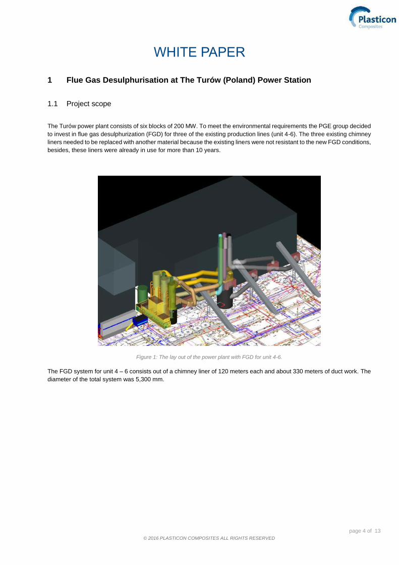
Figure 1: The lay out of the power plant with FGD for unit 4-6.
The FGD system for unit 4 – 6 consists out of a chimney liner of 120 meters each and about 330 meters of duct work. The
diameter of the total system was 5,300 mm.

page 5 of 13
© 2016 PLASTICON COMPOSITES ALL RIGHTS RESERVED
WHITE PAPER
2 Design criteria
2.1 Introduction
In 2010 PGE made a feasibility study for the selection of the right material for the absorbers, the ducts and chimney liner.
Based on the following criteria they decided on fiberglass reinforced polyester, FRP, to be the right choice for the flue gas
desulphurization unit of this new power plant. The criteria:
a) Chemical (and corrosion) resistance b) Temperature resistance c) Ash load d) Lifetime and guarantee period e) Installation time of the chimney liner f) Cost
a) Chemical resistance
Each unit is designed for a maximum flue gas flow of 1,280,000 Nm3/h with a composition of the gas according to table 1.
Chemical Max. concentration
H₂O 25.6 [vol%]
SO₂ 2,500 [mg/m3]
SO₃ 20 [mg/m3]
HCl 20 - 200 [mg/m3]
HF 5 – 30 [mg/m3]
CO 500 [mg/m3]
NOₓ 400 [mg/m3]
Table 1: The composition of the flue gas
The engineers of PGE decided the three existing chimney liners, consisting out of borosilicate blocks, needed to be
replaced because of two reasons: First, because of the wet circumstances of the FGD system. Secondly, due to the
concentration of hydrogen fluoride (HF) in the gas flow. To meet these operating conditions, fiberglass, alloy or titanium
cladded steel would be the right construction material.
b) Temperature resistance
Normally, the flue gas desulphurization unit would work at a temperature of 70°C. However, during the construction period
the flue gas desulphurization of unit 4 and 6 would not be operative, these units would have to operate under by-pass
conditions, reaching higher temperatures than normal. As soon as the last unit (5) was installed, the total system would be
operational for flue gas desulfurization.
During by-pass operation (unit 4 in two years’ time) the temperature of the system can reach temperatures up to max
163°C (for 2 hours, normal 141°C) and under maximum SO2 concentration. The design of the system was based on 22
shut downs per annum. These large repetitive differences in temperature (20 – 160 °C, 22 shut downs per annum) were
very important in deciding the right construction material. Fiberglass can perfectly withstand these extreme temperature
differences.
page 6 of 13
© 2016 PLASTICON COMPOSITES ALL RIGHTS RESERVED
WHITE PAPER
c) Ash load
The expected ash load in the ducts (150 kg/m2), the weight of the duct itself and the insulation properties of the material
were important criteria for the design of the steel support construction. FRP is lightweight material, especially compared to
steel with borosilicate blocks, meaning a saving of 25-30% on steel supports in design was achieved. On top of that,
fiberglass is also better resistant to the excessive quantity of condensate that accumulates in the duct sections, due to
excellent insulation properties.
d) Lifetime and guarantee period
PGE insisted on a long lifetime (> 30 years) of the process equipment and therefore asked for a guarantee period of five
years, based on the maximum design data. Fiberglass can easily hold this lifetime, specifically under circumstances during
flue gas desulphurization. The first fiberglass liners for FGD already were installed in 1973 in Salt Lake City in the USA
(Brady 2015) and 21 years ago in Ingolstadt Germany (van Buren 2014). The first stacks for waste incineration plants,
where the design conditions are generally more extreme, were installed in 1985 at the Rotterdam waste incineration plant
(AVR).
Based on the experience with FRP, a guarantee period of 60 months or five years after commissioning of the power plant
was no issue. This demand could easily be fulfilled by Plasticon Composites.
e) Installation time of the chimney liner
PGE insisted in demolishing the old borosilicate brick chimney liner and installing the new chimney liner within a time frame
of 40 days. Plasticon Composites had 25 days to install a new chimney liner of a diameter of 5,300 mm and 120-meter
height plus corresponding by-pass section, while the other five blocks of the power plant remained in operation. This short
installation time would avoid a long shutdown of the power plant, meaning high costs.
The power plant was fully occupied so loss of one line during an extended period time was very expensive and
impermissible. PGE already planned the investment of an extra block of 200 MW to fulfil the needs of their client. Plasticon
Composites presented a very detailed plan for the installation of a new fiberglass chimney liner in maximum 25 days. The
installation of the first liner including by-pass took 25 working days. The installation of the last liner was ready within 19
working days.
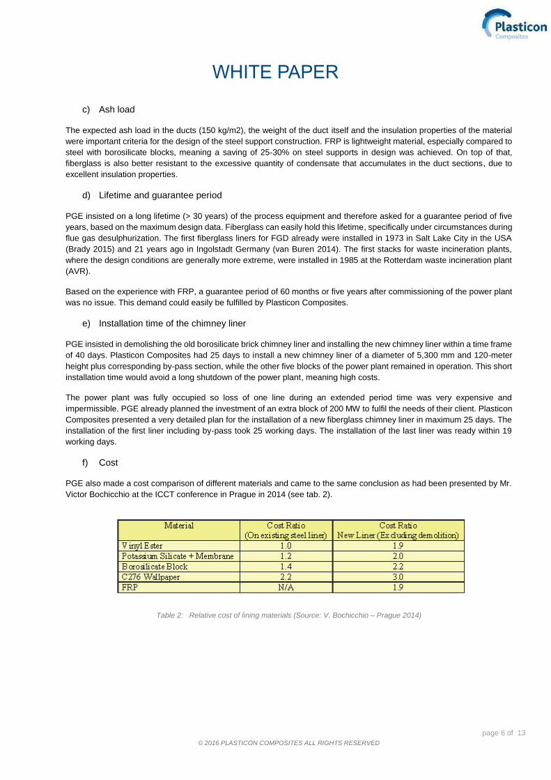
f) Cost
PGE also made a cost comparison of different materials and came to the same conclusion as had been presented by Mr.
Victor Bochicchio at the ICCT conference in Prague in 2014 (see tab. 2).
Table 2: Relative cost of lining materials (Source: V. Bochicchio – Prague 2014)
page 7 of 13
© 2016 PLASTICON COMPOSITES ALL RIGHTS RESERVED
WHITE PAPER
2.2 Conclusion
Based on the above mentioned design criteria, the engineers of PGE have written a design specification and advise to
apply fiberglass material for the construction of the chimney liners, duct systems and by-pass system. FRP material proofs
to have good mechanical properties and it has excellent chemical resistance. Furthermore, its temperature resistance
properties and the fact that the material has a long life time are important criteria to select the preferred material. And last
but not least, the competitive pricing for the construction of an FRP chimney liner and duct work contributes to the statement
that the application of FRP is a well thought out solution.
page 8 of 13
© 2016 PLASTICON COMPOSITES ALL RIGHTS RESERVED
WHITE PAPER
3 Production of the chimney liner and ducts
3.1 Filament winding of the fiberglass reinforced polyester (FRP) cans
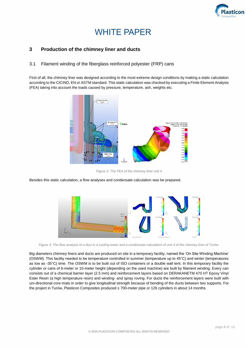
First of all, the chimney liner was designed according to the most extreme design conditions by making a static calculation
according to the CICIND, EN or ASTM standard. This static calculation was checked by executing a Finite Element Analysis
(FEA) taking into account the loads caused by pressure, temperature, ash, weights etc.
Figure 2: The FEA of the chimney liner unit 4
Besides this static calculation, a flow analyses and condensate calculation was be prepared.
Figure 3: The flow analysis of a duct in a cooling tower and a condensate calculation of unit 4 of the chimney liner of Turów.
Big diameters chimney liners and ducts are produced on site in a temporary facility, named the ‘On Site Winding Machine’
(OSWM). This facility needed to be temperature controlled in summer (temperature up to 45°C) and winter (temperatures
as low as -35°C) time. The OSWM is to be built out of ISO containers or a double wall tent. In this temporary facility the
cylinder or cans of 6-meter or 10-meter height (depending on the used machine) are built by filament winding. Every can
consists out of a chemical barrier layer (2.5 mm) and reinforcement layers based on DERAKANETM 470 HT Epoxy Vinyl
Ester Resin (a high temperature resin) and winding- and spray roving. For ducts the reinforcement layers were built with
uni-directional core-mats in order to give longitudinal strength because of bending of the ducts between two supports. For
the project in Turów, Plasticon Composites produced ± 700-meter pipe or 126 cylinders in about 14 months.

page 9 of 13
© 2016 PLASTICON COMPOSITES ALL RIGHTS RESERVED
WHITE PAPER
3.2 Pre-assembly of the cans
In order to fulfil the condition to install the chimney liner within a time frame of 25 days, Plasticon Composites prepared
segments of 24 meters, made out of four cans. These segments were still easy to handle (approximately 25 ton) and could
be lifted by the crane.
Figure 4: Pre-assembly of the cans.
page 10 of 13
© 2016 PLASTICON COMPOSITES ALL RIGHTS RESERVED
WHITE PAPER
4 Installation of the chimney liner and ducts
4.1 Demolition of the existing chimney liner
A subcontractor of PGE took care of the demolition of the existing chimney liner. They removed every borosilicate brick via
the lower exit of the concrete stack. During this demolition it was not possible to prepare the new chimney liner in the
concrete stack although the space was there. It was not safe, and during the demolition a lot of dust was produced. The
demolition of the brick liner took 15 days.
4.2 Installation of the chimney liner Unit 4
Plasticon Composites made a detailed installation planning to secure the maximum installation period of 25 days would
not be exceeded and to avoid a possible penalty of € 85,000 per day due to a longer shutdown of the power plant. It was
clear that the installation of the new chimney liner could not be done in the lower part of the concrete stack. The demolition
of the brick liner caused a lot of dust and HSE conditions could not be assured. This meant the installation had to be done
using the inlet or the outlet of the concrete stack. As the inlet was blocked during demolition and the time frame (25 days)
was too short to build the new fiberglass chimney liner and by-pass out of the 25 cans of 6 meters, this was not an option.
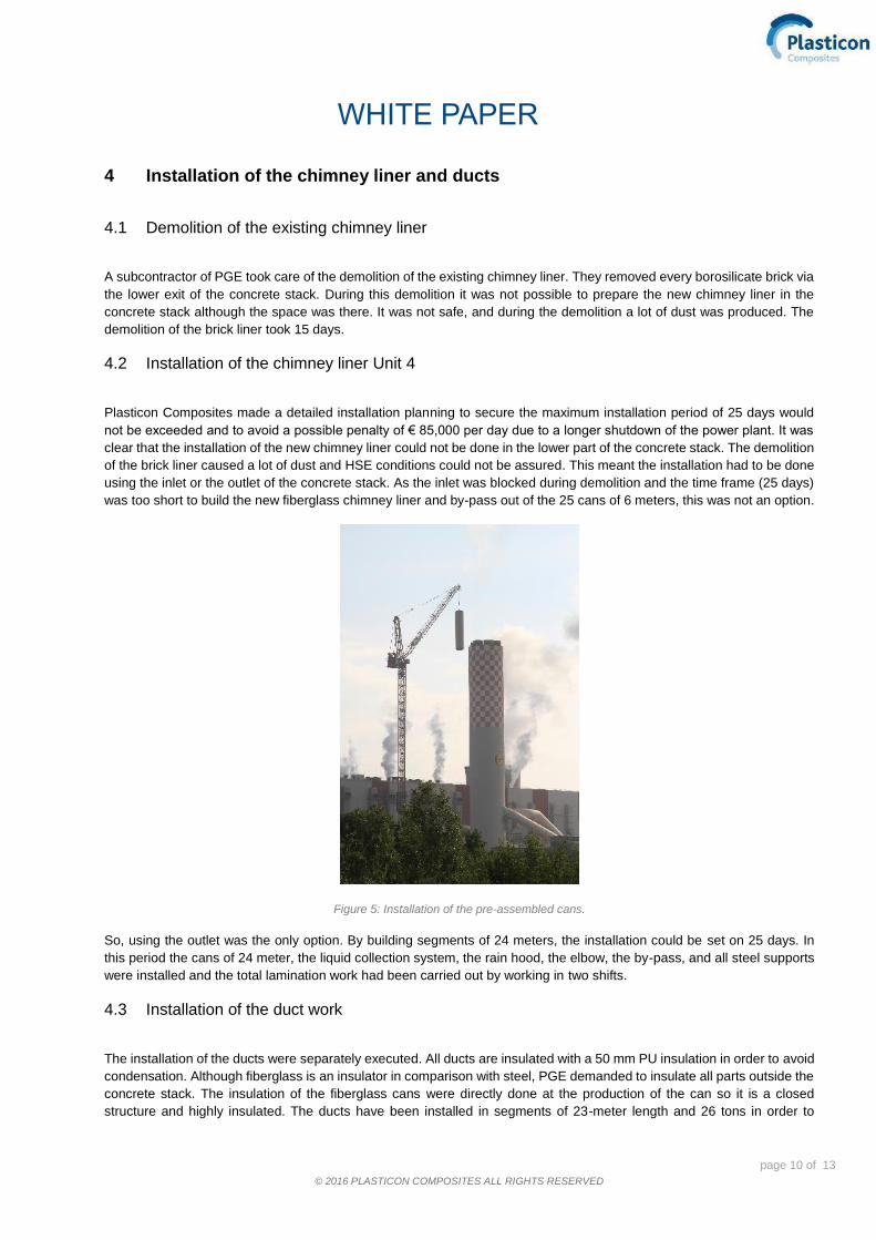
Figure 5: Installation of the pre-assembled cans.
So, using the outlet was the only option. By building segments of 24 meters, the installation could be set on 25 days. In
this period the cans of 24 meter, the liquid collection system, the rain hood, the elbow, the by-pass, and all steel supports
were installed and the total lamination work had been carried out by working in two shifts.
4.3 Installation of the duct work
The installation of the ducts were separately executed. All ducts are insulated with a 50 mm PU insulation in order to avoid
condensation. Although fiberglass is an insulator in comparison with steel, PGE demanded to insulate all parts outside the
concrete stack. The insulation of the fiberglass cans were directly done at the production of the can so it is a closed
structure and highly insulated. The ducts have been installed in segments of 23-meter length and 26 tons in order to

page 11 of 13
© 2016 PLASTICON COMPOSITES ALL RIGHTS RESERVED
WHITE PAPER
prevent disturbance during installation of all other components in the power plant, by using the maximum capacity of the
huge tower crane.
Figure 6: Transport and installation of the duct work.
page 12 of 13
© 2016 PLASTICON COMPOSITES ALL RIGHTS RESERVED
WHITE PAPER
5 NEW developments in the FRP business
5.1 Variable mould
Every chimney liner or duct work in fiberglass has its own dimensions due to the capacity of the power plant and the
process design of the flue gas desulphurization. In order to be competitive, Plasticon Composites designed a variable
mould in order to produce every diameter with one single mould. This mould is built out of fiberglass lamellae and can be
varied from 7 till 12.5-meter diameter or 12 till 20-meter diameter.
(This innovation was translated into the concept of ‘Field Fabricated Fiberglass Tanks’ (FFFT) for the gypsum slurry and
other chemicals. Save money on transport and reduce production costs: www.fieldfabricatedfiberglasstanks.com)
5.2 FRP Absorber
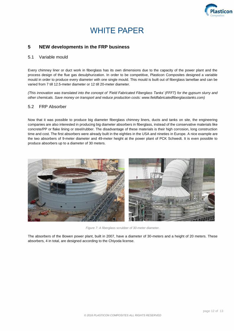
Now that it was possible to produce big diameter fiberglass chimney liners, ducts and tanks on site, the engineering
companies are also interested in producing big diameter absorbers in fiberglass, instead of the conservative materials like
concrete/PP or flake lining or steel/rubber. The disadvantage of these materials is their high corrosion, long construction
time and cost. The first absorbers were already built in the eighties in the USA and nineties in Europe. A nice example are
the two absorbers of 9-meter diameter and 49-meter height at the power plant of PCK Schwedt. It is even possible to
produce absorbers up to a diameter of 30 meters.
Figure 7: A fiberglass scrubber of 30-meter diameter.
The absorbers of the Bowen power plant, built in 2007, have a diameter of 30-meters and a height of 20 meters. These
absorbers, 4 in total, are designed according to the Chiyoda license.
page 13 of 13
© 2016 PLASTICON COMPOSITES ALL RIGHTS RESERVED
WHITE PAPER
6 References
Bochicchio V, 2014. An overview of lining materials for use in the renovation of existing power plant chimneys, ICCI 2014
Prague.
Brady B, 2015. Development of GRP in the chimney industry, CICIND Conference 2015 Boston.
Buren, van A, 2014. Composite solutions as problem solvers in industrial chimneys and cooling towers, ICCT 2014 Prague.
Related Documents