The information contained in this publication was correct at the time of going to print. In the interest of development the right is reserved to change specifications, design or equipment at any time without notice and without incurring any obligations. This publication, or part thereof, may not be reproduced nor translated without our approval. Errors and omissions excepted. © Ford Motor Company 2012 All rights reserved. Part Number: 08/2012 20120601095727

Welcome message from author
This document is posted to help you gain knowledge. Please leave a comment to let me know what you think about it! Share it to your friends and learn new things together.
Transcript

The information contained in this publication was correct at the time of going to print. In the interest ofdevelopment the right is reserved to change specifications, design or equipment at any time withoutnotice and without incurring any obligations. This publication, or part thereof, may not be reproduced nortranslated without our approval. Errors and omissions excepted.© Ford Motor Company 2012
All rights reserved.Part Number: 08/2012 20120601095727

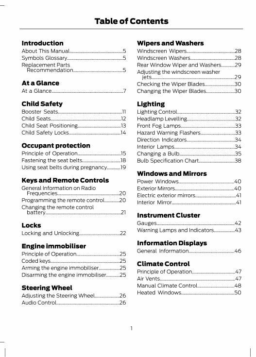
IntroductionAbout This Manual...........................................5Symbols Glossary.............................................5Replacement Parts
Recommendation........................................5
At a GlanceAt a Glance..........................................................7
Child SafetyBooster Seats....................................................11Child Seats.........................................................12Child Seat Positioning...................................13Child Safety Locks..........................................14
Occupant protectionPrinciple of Operation...................................15Fastening the seat belts...............................18Using seat belts during pregnancy...........19
Keys and Remote ControlsGeneral Information on Radio
Frequencies..................................................20Programming the remote control............20Changing the remote control
battery.............................................................21
LocksLocking and Unlocking.................................22
Engine immobiliserPrinciple of Operation...................................25Coded keys........................................................25Arming the engine immobiliser.................25Disarming the engine immobiliser...........25
Steering WheelAdjusting the Steering Wheel....................26Audio Control...................................................26
Wipers and WashersWindscreen Wipers.......................................28Windscreen Washers....................................28Rear Window Wiper and Washers...........29Adjusting the windscreen washer
jets...................................................................29Checking the Wiper Blades........................30Changing the Wiper Blades.......................30
LightingLighting Control...............................................32Headlamp Levelling.......................................32Front Fog Lamps............................................33Hazard Warning Flashers............................33Direction Indicators.......................................34Interior Lamps.................................................34Changing a Bulb.............................................35Bulb Specification Chart.............................38
Windows and MirrorsPower Windows.............................................40Exterior Mirrors................................................40Electric exterior mirrors.................................41Interior Mirror....................................................41
Instrument ClusterGauges...............................................................42Warning Lamps and Indicators.................43
Information DisplaysGeneral Information.....................................46
Climate ControlPrinciple of Operation...................................47Air Vents.............................................................47Manual Climate Control..............................48Heated Windows...........................................50
1
Table of Contents
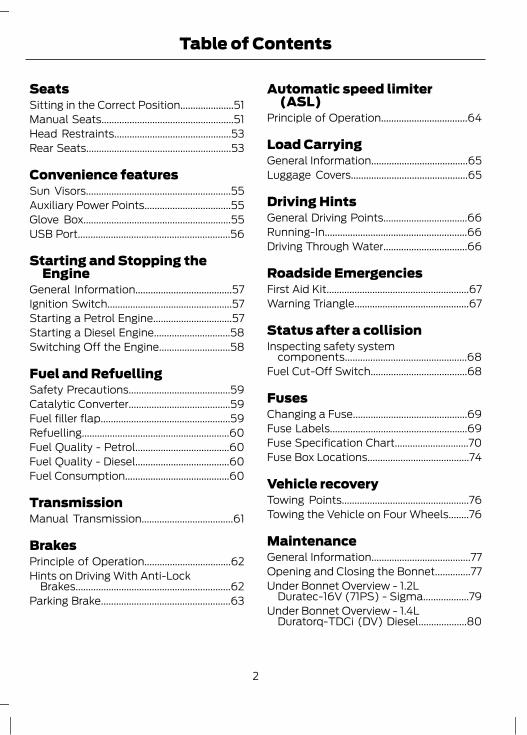
SeatsSitting in the Correct Position.....................51Manual Seats....................................................51Head Restraints..............................................53Rear Seats.........................................................53
Convenience featuresSun Visors.........................................................55Auxiliary Power Points..................................55Glove Box..........................................................55USB Port............................................................56
Starting and Stopping theEngine
General Information......................................57Ignition Switch.................................................57Starting a Petrol Engine...............................57Starting a Diesel Engine..............................58Switching Off the Engine............................58
Fuel and RefuellingSafety Precautions........................................59Catalytic Converter........................................59Fuel filler flap...................................................59Refuelling..........................................................60Fuel Quality - Petrol.....................................60Fuel Quality - Diesel.....................................60Fuel Consumption.........................................60
TransmissionManual Transmission....................................61
BrakesPrinciple of Operation..................................62Hints on Driving With Anti-Lock
Brakes.............................................................62Parking Brake...................................................63
Automatic speed limiter(ASL)
Principle of Operation..................................64
Load CarryingGeneral Information......................................65Luggage Covers..............................................65
Driving HintsGeneral Driving Points.................................66Running-In........................................................66Driving Through Water.................................66
Roadside EmergenciesFirst Aid Kit........................................................67Warning Triangle.............................................67
Status after a collisionInspecting safety system
components................................................68Fuel Cut-Off Switch......................................68
FusesChanging a Fuse.............................................69Fuse Labels......................................................69Fuse Specification Chart.............................70Fuse Box Locations........................................74
Vehicle recoveryTowing Points..................................................76Towing the Vehicle on Four Wheels........76
MaintenanceGeneral Information.......................................77Opening and Closing the Bonnet..............77Under Bonnet Overview - 1.2L
Duratec-16V (71PS) - Sigma..................79Under Bonnet Overview - 1.4L
Duratorq-TDCi (DV) Diesel...................80
2
Table of Contents
Engine Oil Dipstick - 1.2L Duratec-16V(71PS) - Sigma.............................................81
Engine Oil Dipstick - 1.4L Duratorq-TDCi(DV) Diesel....................................................81
Engine Oil Check.............................................81Engine Coolant Check..................................83Brake and Clutch Fluid Check...................83Power Steering Fluid Check.......................84Washer Fluid Check......................................84Technical Specifications.............................85
Vehicle CareCleaning the Exterior....................................88Cleaning the Interior.....................................89Repairing Minor Paint Damage.................89
Vehicle batteryBattery care.....................................................90Jump-Starting the Vehicle.........................90
Wheels and TyresGeneral Information......................................92Changing a Road Wheel..............................92Tyre Care............................................................97Technical Specifications..............................97
Vehicle identificationVehicle Identification Number..................99
Capacities and Specific-ations
Weights............................................................100Dimensions......................................................101
3
Table of Contents

4
ABOUT THIS MANUALThank you for choosing Ford. Werecommend that you take some time toget to know your vehicle by reading thismanual. The more that you know about it,the greater the safety and pleasure youwill get from driving it.
WARNINGAlways drive with due care andattention when using and operatingthe controls and features on your
vehicle.
Note: This manual describes productfeatures and options available throughoutthe range, sometimes even before they aregenerally available. It may describe optionsnot fitted to your vehicle.Note: Some of the illustrations in thismanual may be used for different models,so may appear different to your vehicle.However, the essential information in theillustrations is always correct.Note: Always use and operate your vehiclein line with all applicable laws andregulations.Note: Pass on this manual when sellingyour vehicle. It is an integral part of thevehicle.
SYMBOLS GLOSSARYSymbols in this handbook
WARNINGYou risk death or serious injury toyourself and others if you do notfollow the instructions highlighted
by the warning symbol.
CAUTIONYou risk damaging your vehicle if youdo not follow the instructionshighlighted by the caution symbol.
Symbols on your vehicle
When you see these symbols, read andfollow the relevant instructions in thishandbook before touching or attemptingadjustment of any kind.
REPLACEMENT PARTSRECOMMENDATIONNow you can be sure that your Fordparts are Ford partsYour Ford has been built to the higheststandards using high quality Ford OriginalParts. As a result, you can enjoy driving itfor many years.Should the unexpected occur and a majorpart needs replacing, we recommend thatyou accept nothing less than Ford OriginalParts.The use of Ford Original Parts ensures thatyour vehicle is repaired to its pre-accidentcondition and maintains its maximumresidual value.Ford Original Parts match Ford's stringentsafety requirements and high standardsof fit, finish and reliability. Quite simply,they represent the best overall repair value,including parts and labour costs.
5
Introduction
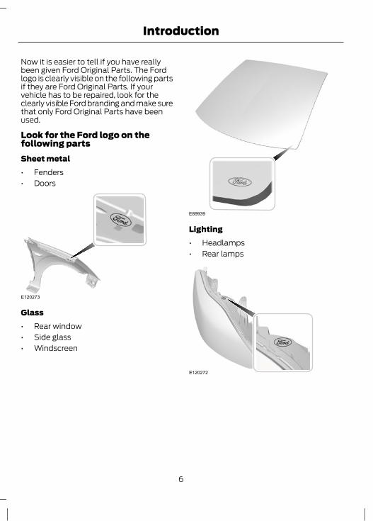
Now it is easier to tell if you have reallybeen given Ford Original Parts. The Fordlogo is clearly visible on the following partsif they are Ford Original Parts. If yourvehicle has to be repaired, look for theclearly visible Ford branding and make surethat only Ford Original Parts have beenused.
Look for the Ford logo on thefollowing partsSheet metal• Fenders• Doors
E120273
Glass• Rear window• Side glass• Windscreen
E89939
Lighting• Headlamps• Rear lamps
E120272
6
Introduction
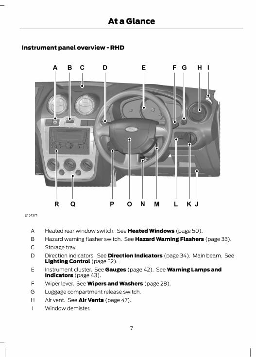
Instrument panel overview - RHD
EA
Q J
CB H ID F G
KLMP O NRE154371
Heated rear window switch. See Heated Windows (page 50).AHazard warning flasher switch. See Hazard Warning Flashers (page 33).BStorage tray.CDirection indicators. See Direction Indicators (page 34). Main beam. SeeLighting Control (page 32).
D
Instrument cluster. See Gauges (page 42). See Warning Lamps andIndicators (page 43).
E
Wiper lever. See Wipers and Washers (page 28).FLuggage compartment release switch.GAir vent. See Air Vents (page 47).HWindow demister.I
7
At a Glance

Driver side storage compartment.JLighting control. See Lighting Control (page 32). Front fog lamps. See FrontFog Lamps (page 33).
K
Headlamp levelling control. See Headlamp Levelling (page 32).LIgnition switch. See Ignition Switch (page 57).MSteering wheel adjustment. See Adjusting the Steering Wheel (page 26).NHorn.OAudio control. See Audio Control (page 26).PClimate controls. See Climate Control (page 47).QAudio unit. See separate handbook.R
Engine idle speed after startingThe engine may idle at a higher speed thannormal immediately after starting fromcold. See Starting a Petrol Engine (page57). See Starting a Diesel Engine (page58).
Warning lamps and indicatorsABS warning lamp
Airbag warning lamp
Brake system warning lamp
Direction indicator
Door open warning lamp
MIL (Malfunction indicator lamp)
Glow plug indicator
Illumination ON indicator
Ignition warning lamp
Low fuel level warning lamp
Main beam indicator
Oil pressure warning lamp
Front fog lamp indicator
Engine check warning lamp
Water in fuel warning lamp
Engine coolant temperaturewarning lamp
8
At a Glance
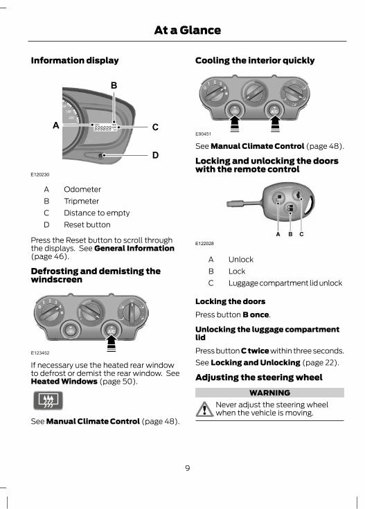
Information display
E120230
C
D
B
A
OdometerATripmeterBDistance to emptyCReset buttonD
Press the Reset button to scroll throughthe displays. See General Information(page 46).
Defrosting and demisting thewindscreen
E123452
If necessary use the heated rear windowto defrost or demist the rear window. SeeHeated Windows (page 50).
E72507
See Manual Climate Control (page 48).
Cooling the interior quickly
E90451
See Manual Climate Control (page 48).
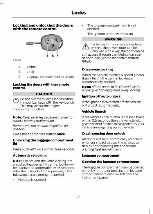
Locking and unlocking the doorswith the remote control
E122028
UnlockALockBLuggage compartment lid unlockC
Locking the doorsPress button B once.
Unlocking the luggage compartmentlidPress button C twice within three seconds.See Locking and Unlocking (page 22).
Adjusting the steering wheelWARNING
Never adjust the steering wheelwhen the vehicle is moving.
9
At a Glance

1
2
E101516
WARNINGMake sure that you fully engage thelocking lever when returning it to itsoriginal position.
3E95179
See Adjusting the Steering Wheel(page 26).
10
At a Glance

BOOSTER SEATS
WARNINGSDo not install a booster seat or abooster cushion with only the lapstrap of the seat belt.Do not install a booster seat or abooster cushion with a seat belt thatis slack or twisted.Do not put the seat belt under yourchild’s arm or behind its back.Do not use pillows, books or towelsto boost your child’s height.Make sure that your children sit in anupright position.Secure children that weigh morethan 15 kilograms but are less than150 centimetres tall in a booster seat
or a booster cushion.
Booster seat (Group 2)
E70710
We recommend that you use a boosterseat that combines a cushion with abackrest instead of a booster cushion only.The raised seating position will allow youto position the shoulder strap of the adultseat belt over the centre of your child’sshoulder and the lap strap tightly acrossits hips.
Booster cushion (Group 3)
E68924
11
Child Safety
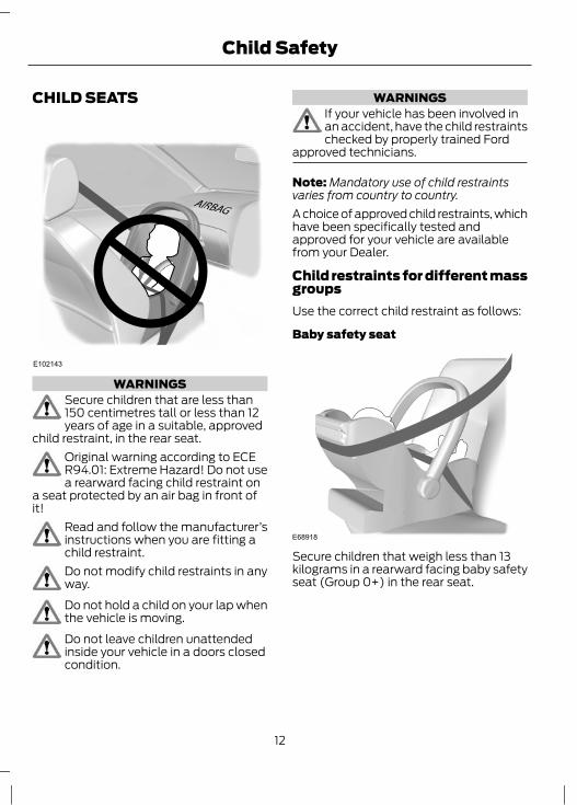
CHILD SEATS
E102143
WARNINGSSecure children that are less than150 centimetres tall or less than 12years of age in a suitable, approved
child restraint, in the rear seat.Original warning according to ECER94.01: Extreme Hazard! Do not usea rearward facing child restraint on
a seat protected by an air bag in front ofit!
Read and follow the manufacturer’sinstructions when you are fitting achild restraint.Do not modify child restraints in anyway.Do not hold a child on your lap whenthe vehicle is moving.Do not leave children unattendedinside your vehicle in a doors closedcondition.
WARNINGSIf your vehicle has been involved inan accident, have the child restraintschecked by properly trained Ford
approved technicians.
Note: Mandatory use of child restraintsvaries from country to country.A choice of approved child restraints, whichhave been specifically tested andapproved for your vehicle are availablefrom your Dealer.
Child restraints for different massgroupsUse the correct child restraint as follows:
Baby safety seat
E68918
Secure children that weigh less than 13kilograms in a rearward facing baby safetyseat (Group 0+) in the rear seat.
12
Child Safety

Child safety seat
E68920
Secure children that weigh between 13 and18 kilograms in a child safety seat (Group1) in the rear seat.
CHILD SEAT POSITIONING
Mass group categoriesSeating positions
IIIIII0+0
22 - 36 kg15 - 25 kg9 - 18 kgUp to 13 kgUp to 10 kg
UF1UF1UF1UF1UF1Front co-driver seat(without PAB)
UF1UF1UF1XXFront co-driver seat(with PAB)
UUUUURear seat (3 point belt)
XXXXXRear seat (lap belt only)
PAB - Passenger airbag.X Not suitable for children in this mass group.U Suitable for universal category child seats approved for use in this mass.UF¹ Suitable for universal category forward facing child seats approved for use in thismass group. However, we recommend that you secure children in a government approvedchild restraint, in the rear seat.
13
Child Safety
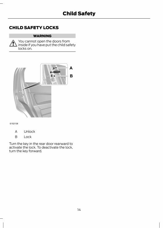
CHILD SAFETY LOCKS
WARNINGYou cannot open the doors frominside if you have put the child safetylocks on.
A
B
E102138
UnlockALockB
Turn the key in the rear door rearward toactivate the lock. To deactivate the lock,turn the key forward.
14
Child Safety

PRINCIPLE OF OPERATION
E123935
AirbagsWARNINGS
Do not modify the front of yourvehicle in any way. This couldadversely affect deployment of the
airbags.Original warning according to ECER94.01: Extreme Hazard! Do not usea rearward facing child restraint on
a seat protected by an airbag in front of it!Wear a seat belt and keep sufficientdistance between yourself and thesteering wheel. Only when you use
the seat belt properly, can it hold you in aposition that allows the airbag to achieveits optimum effect.
WARNINGSHave repairs to the steering wheel,steering column, seats, airbags andseat belts carried out by properly
trained technicians from Ford authoriseddealerships.
Keep the areas in front of the airbagsfree from obstruction. Do not affixanything to or over the airbag covers.Do not poke sharp objects into areaswhere airbags are fitted. This coulddamage and adversely affect
deployment of the airbags.The airbag may only deploy with theignition switch in the on (II) position.
15
Occupant protection

WARNINGSAlways keep the areas in front of theairbags free. Never affix anything toor over these areas.If you are too close to an inflatingairbag, it could seriously injure you.Move your seat as far back as
practical to allow room for airbag inflation.Several airbag system componentsget hot after inflation. Do not touchafter inflation.Fitment of certain accessories e.g.bull bars or nudge bars may causeinadvertent or premature
deployment of air bags.
Note: You will hear a loud bang and see acloud of harmless powdery residue if anairbag deploys. This is normal.Note: Only wipe airbag covers with a dampcloth.Your vehicle is equipped with an event datarecorder which is capable of collecting andstoring data during a crash or near crashevent. The recorded information may assistin the investigation of such an event. Toaccess this information special equipmentmust be directly connected to therecording modules. Ford does not accessevent data recorder information withoutobtaining consent unless pursuant to acourt order or where required by lawenforcement, other government authoritiesor other third parties may seek access tothe information independent of Ford.
E123936
The airbag is a supplementary restraintsystem. It is designed to be used in additionto seat belts to help protect against headand chest injuries in certain moderate tosevere frontal collisions.
The airbag system is not visible until it isactivated. The air bag system is designedto deploy the driver and passenger frontair bags in certain frontal and front angledcollisions.
16
Occupant protection

Because the system senses crash severity,some frontal and side collisions will notinflate the airbags. Front airbags are notdesigned to inflate in rollover, rear and lowspeed impacts.The restraint system comprises:• a driver airbag• a front passenger airbag• crash sensors• an airbag warning lamp• an electronic control and diagnostic
unit.
Driver and front passenger airbagsYour vehicle is equipped with an air bag forthe driver, located in the steering wheeland a passenger air bag is located in theinstrument panel above the glovecompartment. The passenger air bag canbe identified by the ‘Airbag’ markembedded on the airbag cover.The seat back must be set correctly for theairbags to be optimally effective. SeeSitting in the Correct Position (page51). This helps to reduce the risk of injuryfrom sitting too close to an inflating airbag.
E102125
The driver and front passenger airbags willdeploy during significant frontal collisionsor collisions that are up to 30 degrees fromthe left or the right. The airbags will inflatewithin a few thousandths of a second anddeflate on contact with the occupants,thus cushioning forward face/bodymovement. During minor frontal collisions,overturns, rear collisions and sidecollisions, the driver and front passengerairbags will not deploy.
WARNINGSIf the passenger airbag cover showssigns of having been removed, thecar should be towed to the nearest
Authorised Ford Dealer for repair. Do notattempt to reinstall the cover. If the vehiclemust be driven then on no account shouldthere be an occupant in the frontpassenger seat.
The airbag(s) and energymanagement retractors will activateonly once. Once activated, the
airbags and energy management retractorswill not function again and must bereplaced immediately. The crash sensormust also be replaced. If the airbag(s) arenot replaced, the un-repaired area willincrease the risk of injury in a collision.
Airbag warning light
E123944
When the ignition switch is turned toposition II, the airbag warning light on theinstrument panel illuminates forapproximately 3 seconds to indicate thatthe system is functional.
17
Occupant protection
If the airbag warning light does notilluminate, if it stays on or illuminatesintermittently or continuously while driving,it means there is a malfunction. Have thesystem checked by an Authorised FordDealer.
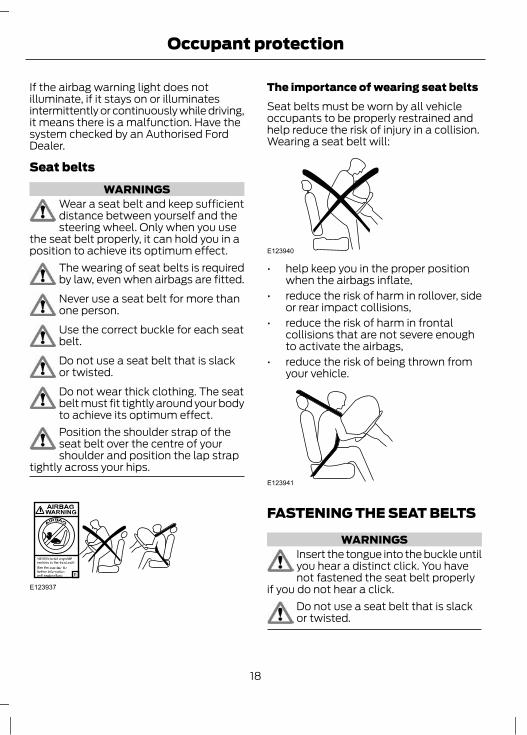
Seat beltsWARNINGS
Wear a seat belt and keep sufficientdistance between yourself and thesteering wheel. Only when you use
the seat belt properly, it can hold you in aposition to achieve its optimum effect.
The wearing of seat belts is requiredby law, even when airbags are fitted.Never use a seat belt for more thanone person.Use the correct buckle for each seatbelt.Do not use a seat belt that is slackor twisted.Do not wear thick clothing. The seatbelt must fit tightly around your bodyto achieve its optimum effect.Position the shoulder strap of theseat belt over the centre of yourshoulder and position the lap strap
tightly across your hips.
E123937
The importance of wearing seat beltsSeat belts must be worn by all vehicleoccupants to be properly restrained andhelp reduce the risk of injury in a collision.Wearing a seat belt will:
E123940
• help keep you in the proper positionwhen the airbags inflate,
• reduce the risk of harm in rollover, sideor rear impact collisions,
• reduce the risk of harm in frontalcollisions that are not severe enoughto activate the airbags,
• reduce the risk of being thrown fromyour vehicle.
E123941
FASTENING THE SEAT BELTS
WARNINGSInsert the tongue into the buckle untilyou hear a distinct click. You havenot fastened the seat belt properly
if you do not hear a click.Do not use a seat belt that is slackor twisted.
18
Occupant protection
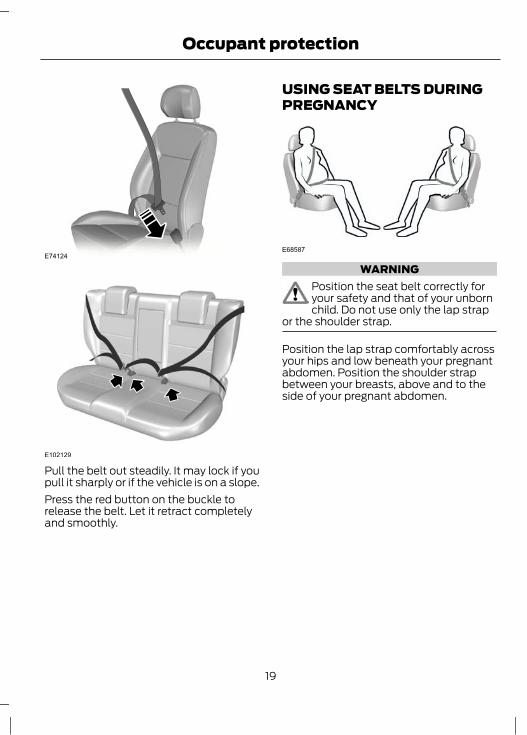
E74124
E102129
Pull the belt out steadily. It may lock if youpull it sharply or if the vehicle is on a slope.Press the red button on the buckle torelease the belt. Let it retract completelyand smoothly.
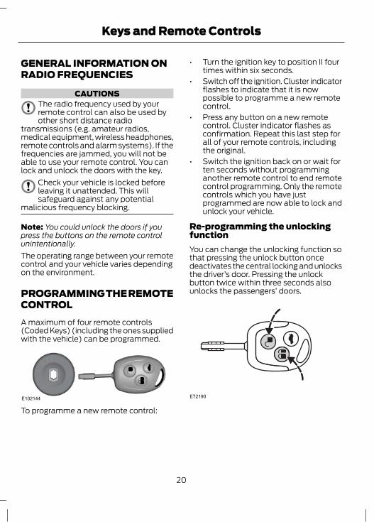
USING SEAT BELTS DURINGPREGNANCY
E68587
WARNINGPosition the seat belt correctly foryour safety and that of your unbornchild. Do not use only the lap strap
or the shoulder strap.
Position the lap strap comfortably acrossyour hips and low beneath your pregnantabdomen. Position the shoulder strapbetween your breasts, above and to theside of your pregnant abdomen.
19
Occupant protection
GENERAL INFORMATION ONRADIO FREQUENCIES
CAUTIONSThe radio frequency used by yourremote control can also be used byother short distance radio
transmissions (e.g. amateur radios,medical equipment, wireless headphones,remote controls and alarm systems). If thefrequencies are jammed, you will not beable to use your remote control. You canlock and unlock the doors with the key.
Check your vehicle is locked beforeleaving it unattended. This willsafeguard against any potential
malicious frequency blocking.
Note: You could unlock the doors if youpress the buttons on the remote controlunintentionally.The operating range between your remotecontrol and your vehicle varies dependingon the environment.
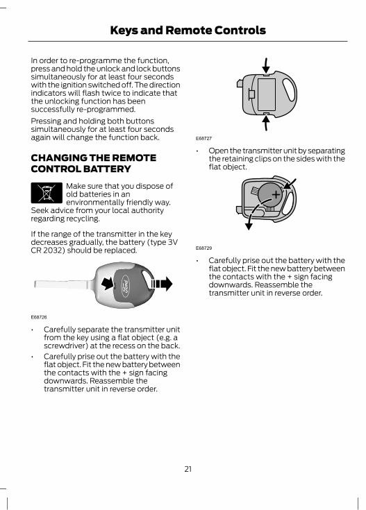
PROGRAMMING THE REMOTECONTROLA maximum of four remote controls(Coded Keys) (including the ones suppliedwith the vehicle) can be programmed.
E102144
To programme a new remote control:
• Turn the ignition key to position II fourtimes within six seconds.
• Switch off the ignition. Cluster indicatorflashes to indicate that it is nowpossible to programme a new remotecontrol.
• Press any button on a new remotecontrol. Cluster indicator flashes asconfirmation. Repeat this last step forall of your remote controls, includingthe original.
• Switch the ignition back on or wait forten seconds without programminganother remote control to end remotecontrol programming. Only the remotecontrols which you have justprogrammed are now able to lock andunlock your vehicle.
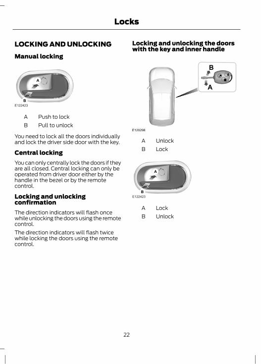
Re-programming the unlockingfunctionYou can change the unlocking function sothat pressing the unlock button oncedeactivates the central locking and unlocksthe driver’s door. Pressing the unlockbutton twice within three seconds alsounlocks the passengers’ doors.
E72190
20
Keys and Remote Controls
In order to re-programme the function,press and hold the unlock and lock buttonssimultaneously for at least four secondswith the ignition switched off. The directionindicators will flash twice to indicate thatthe unlocking function has beensuccessfully re-programmed.Pressing and holding both buttonssimultaneously for at least four secondsagain will change the function back.
CHANGING THE REMOTECONTROL BATTERY
E107998
Make sure that you dispose ofold batteries in anenvironmentally friendly way.
Seek advice from your local authorityregarding recycling.
If the range of the transmitter in the keydecreases gradually, the battery (type 3VCR 2032) should be replaced.
E68726
• Carefully separate the transmitter unitfrom the key using a flat object (e.g. ascrewdriver) at the recess on the back.
• Carefully prise out the battery with theflat object. Fit the new battery betweenthe contacts with the + sign facingdownwards. Reassemble thetransmitter unit in reverse order.
E68727
• Open the transmitter unit by separatingthe retaining clips on the sides with theflat object.
E68729
• Carefully prise out the battery with theflat object. Fit the new battery betweenthe contacts with the + sign facingdownwards. Reassemble thetransmitter unit in reverse order.
21
Keys and Remote Controls
LOCKING AND UNLOCKINGManual locking
A
BE122423
Push to lockAPull to unlockB
You need to lock all the doors individuallyand lock the driver side door with the key.
Central lockingYou can only centrally lock the doors if theyare all closed. Central locking can only beoperated from driver door either by thehandle in the bezel or by the remotecontrol.
Locking and unlockingconfirmationThe direction indicators will flash oncewhile unlocking the doors using the remotecontrol.The direction indicators will flash twicewhile locking the doors using the remotecontrol.
Locking and unlocking the doorswith the key and inner handle
E120298
A
B
UnlockALockB
A
BE122423
LockAUnlockB
22
Locks
Locking and unlocking the doorswith the remote control
E122028
UnlockALockBLuggage compartment lid unlockC
Locking the doors with the remotecontrol
CAUTIONDo not put metal accessories/otherimmobilizer keys with the key bunch.This may affect the engine
immobilizer function.
Note: Keep each key separate in order toavoid a starting malfunction.Remote will not operate at ignition onposition.Press the appropriate button once.
Unlocking the luggage compartmentlidPress button C twice within three seconds.
Automatic relockingNOTE: To prevent the vehicle being leftunlocked inadvertently, central locking willbe reactivated automatically 45 secondsafter the unlock button is pressed, if thefollowing occurs during the period.• No door is opened.
• The luggage compartment is notopened.
• The ignition is not switched on.WARNING
If a failure in the vehicle's electricalsystem, the drivers door can beunlocked with a key, the boot can be
still access through the folding rear seator boot lock (where respective featurefitted).
Drive away lockingWhen the vehicle reaches a speed greaterthan 7 Km/h, the central locking isautomatically applied.Note: All the doors to be closed fully forproper functioning of drive away locking.
Ignition off auto unlockIf the ignition is switched off the vehiclewill unlock automatically.
Vehicle SearchIf the remote Lock button is pressed twicewithin 0.5 seconds then the vehicle willgive few short flashes to easily identify yourvehicle amongst a group of vehicle.
Crash sensing door unlockAll doors will be automatically unlockedwhen an impact causes the airbags todeploy and following this the hazardwarning flashers will flash.
Luggage compartment
Opening the luggage compartmentThe luggage compartment can be openedeither by remote or pressing the luggagecompartment release switch near theinstrument panel.
23
Locks
E121245
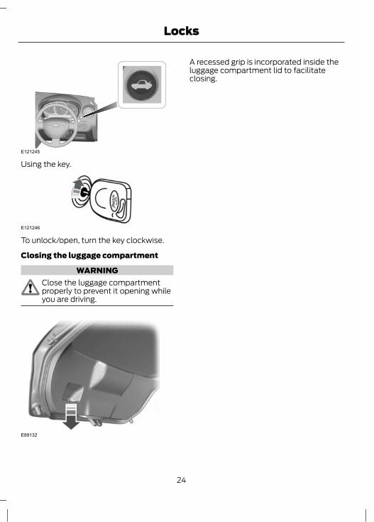
Using the key.
E121246
To unlock/open, turn the key clockwise.
Closing the luggage compartment
WARNINGClose the luggage compartmentproperly to prevent it opening whileyou are driving.
E89132
A recessed grip is incorporated inside theluggage compartment lid to facilitateclosing.
24
Locks
PRINCIPLE OF OPERATIONThe engine immobiliser is a theft protectionsystem that prevents someone fromstarting the engine with an incorrectlycoded key.
CODED KEYSNote: Do not shield your keys with metalobjects. This may prevent the receiver fromrecognising your key as a valid one.Note: Have all of your remaining keyserased and recoded if you lose a key. Askyour dealer for further information. Havereplacement keys recoded together withyour existing keys.If you lose a key, you can obtain areplacement from your Ford Dealer. Ifpossible, provide them with the keynumber from the tag provided with theoriginal keys. You can also obtainadditional keys from your Ford Dealer.
ARMING THE ENGINEIMMOBILISERThe engine immobiliser is armedautomatically a short time after you haveswitched the ignition off.The indicator in the instrument cluster willflash to confirm that the system isoperating.
DISARMING THE ENGINEIMMOBILISERSwitching on the ignition disarms thesystem if the correct code is recognised.The indicator illuminates forapproximately three seconds and thenextinguishes.
If the indicator illuminates constantly forone minute or flashes for approximatelyone minute and then repeatedly at irregularintervals, the system did not recognise thekey code or a system fault is present.Remove the key and try again.If the engine does not start, a systemmalfunction has occurred. Have the systemchecked by an expert immediately.
25
Engine immobiliser

ADJUSTING THE STEERINGWHEEL
E102147
WARNINGNever adjust the steering wheelwhen the vehicle is moving.
Release the locking lever to adjust theheight of the steering wheel.Return the lever to its original position tosecure the wheel.See Sitting in the Correct Position (page51).
AUDIO CONTROLSelect radio, CD or cassette mode on theaudio unit.The following functions can be operatedwith the remote control:
Volume
E153170
Volume up: Press the VOL + button on theback of the remote control.Volume down: Press the VOL - button onthe back of the remote control.
Seek
E153171
Move the lever up or down:
26
Steering Wheel
• In radio mode, this will locate the nextradio station up or down the frequencyband.
• In CD, MP3, USB and Bluetoothaudio mode, it will select the next orprevious track.
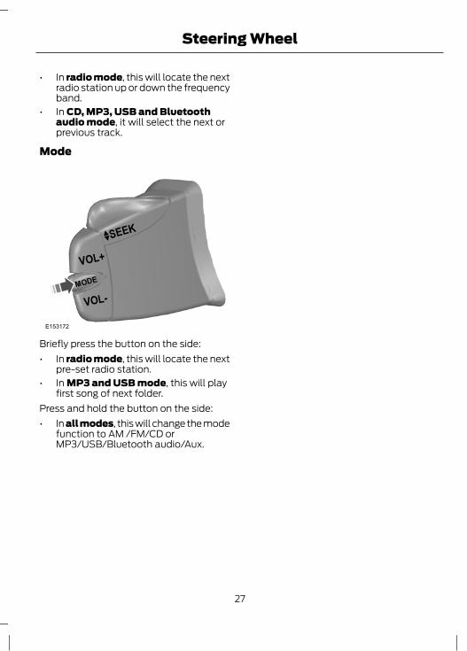
Mode
E153172
Briefly press the button on the side:• In radio mode, this will locate the next
pre-set radio station.• In MP3 and USB mode, this will play
first song of next folder.Press and hold the button on the side:• In all modes, this will change the mode
function to AM /FM/CD orMP3/USB/Bluetooth audio/Aux.
27
Steering Wheel

WINDSCREEN WIPERS
E124013
D
B
C
A
Single wipeAIntermittent wipingBNormal wipingCHigh speed wipingD
Intermittent wipingFixed intermittent
E124015
B
Select the wiper switch to position B forintermittent wiping.However wiping delay can be programmedas follows.1. Switch on the ignition.
2. Set the wiper switch to intermittentposition.
3. Move the wiper switch to off positionwhen the wiper comes to park position.
Note: Wiping delay timing will start fromhere to until the wiper switch is moved toposition B.4. Move the wiper back to position B for
the required time delay.Note: The user programmed timer resets,when the wiper switch is moved to low/highspeed or when the ignition is switched off.Variable intermittent
E124014
B
Select wipe interval with rotary switch: 1 =Short time interval. 6 = Extended timeinterval.
WINDSCREEN WASHERS
E72174
WARNINGDo not operate the windscreenwasher for more than 10 seconds orwhen the reservoir is empty.
28
Wipers and Washers
When the button at the end of the lever ispressed the washer will work inconjunction with the wiper operating fourtimes.Once the wash/wipe cycle is completed,the wipers will pause and then performone more wipe to clear the screen.
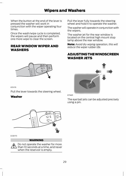
REAR WINDOW WIPER ANDWASHERS
E72175
Pull the lever towards the steering wheel.
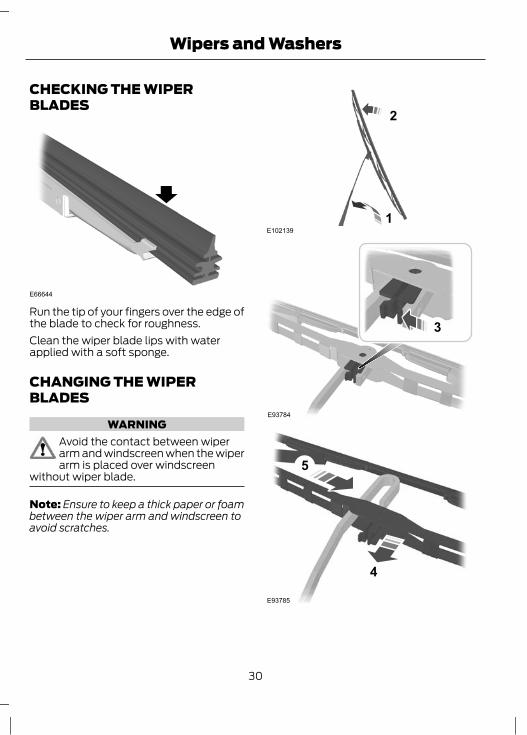
Washer
E120173
WARNINGDo not operate the washer for morethan 10 seconds at a time, and neverwhen the reservoir is empty.
Pull the lever fully towards the steeringwheel and hold it to operate the washer.The washer will operate in conjunction withthe wipers.The washer jet for the rear window islocated on the central high mount stoplamp above the rear window.Note: Avoid dry wiping operation, this willreduce the wiper rubber life.
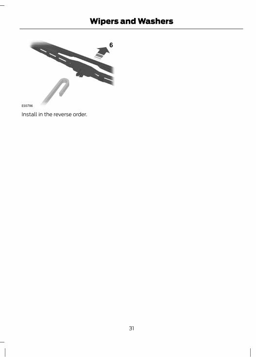
ADJUSTING THE WINDSCREENWASHER JETS
E73425
The eye ball jets can be adjusted preciselyusing a pin.
29
Wipers and Washers
CHECKING THE WIPERBLADES
E66644
Run the tip of your fingers over the edge ofthe blade to check for roughness.Clean the wiper blade lips with waterapplied with a soft sponge.
CHANGING THE WIPERBLADES
WARNINGAvoid the contact between wiperarm and windscreen when the wiperarm is placed over windscreen
without wiper blade.
Note: Ensure to keep a thick paper or foambetween the wiper arm and windscreen toavoid scratches.
E1021391
2
E93784
3
5
4
E93785
30
Wipers and Washers
6
E93786
Install in the reverse order.
31
Wipers and Washers
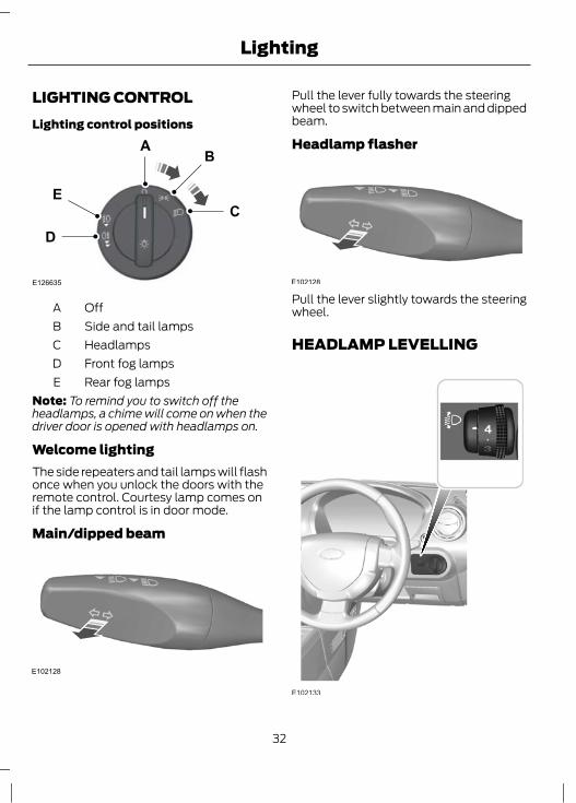
LIGHTING CONTROLLighting control positions
E126635
D
E
OffASide and tail lampsBHeadlampsCFront fog lampsDRear fog lampsE
Note: To remind you to switch off theheadlamps, a chime will come on when thedriver door is opened with headlamps on.
Welcome lightingThe side repeaters and tail lamps will flashonce when you unlock the doors with theremote control. Courtesy lamp comes onif the lamp control is in door mode.
Main/dipped beam
E102128
Pull the lever fully towards the steeringwheel to switch between main and dippedbeam.
Headlamp flasher
E102128
Pull the lever slightly towards the steeringwheel.
HEADLAMP LEVELLING
E102133
32
Lighting
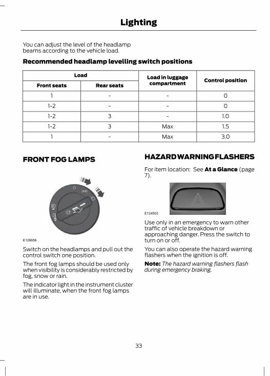
You can adjust the level of the headlampbeams according to the vehicle load.
Recommended headlamp levelling switch positions
Control positionLoad in luggagecompartment
Load
Rear seatsFront seats
0--1
0--1-2
1.0-31-2
1.5Max31-2
3.0Max-1
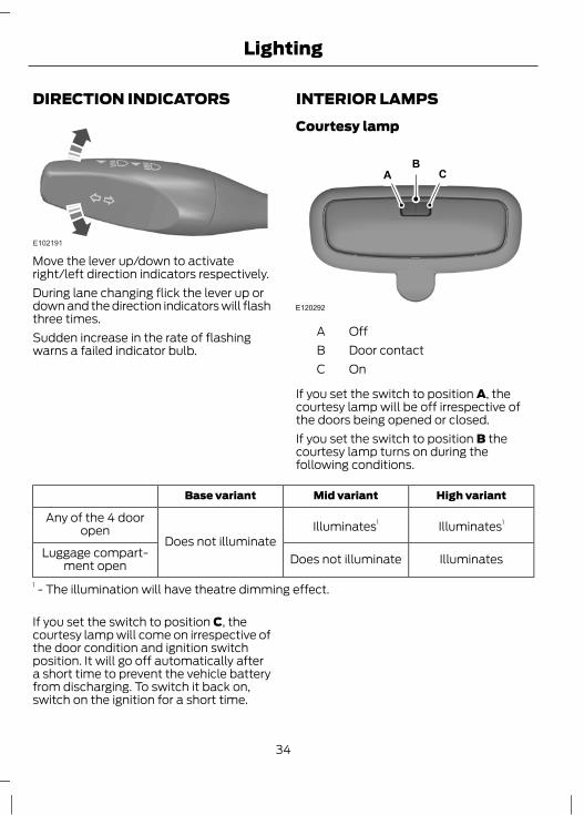
FRONT FOG LAMPS
E126656
Switch on the headlamps and pull out thecontrol switch one position.The front fog lamps should be used onlywhen visibility is considerably restricted byfog, snow or rain.The indicator light in the instrument clusterwill illuminate, when the front fog lampsare in use.
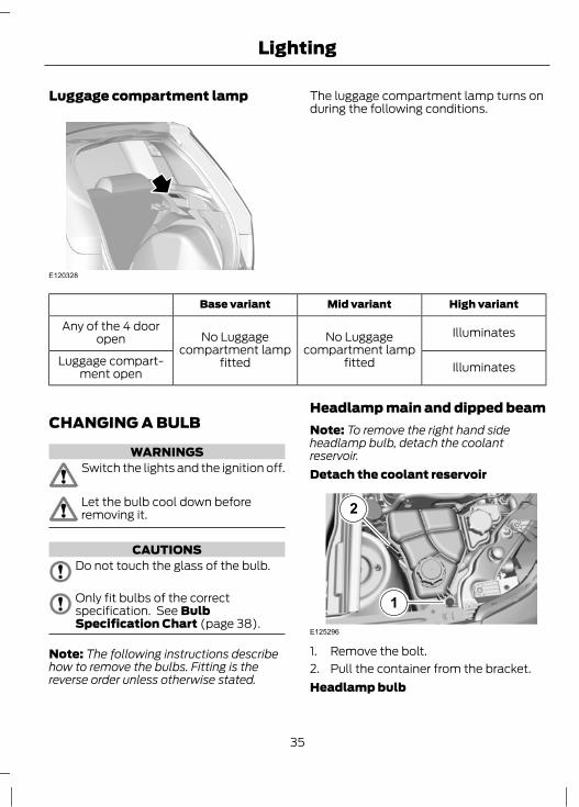
HAZARD WARNING FLASHERSFor item location: See At a Glance (page7).
E124503
Use only in an emergency to warn othertraffic of vehicle breakdown orapproaching danger. Press the switch toturn on or off.You can also operate the hazard warningflashers when the ignition is off.Note: The hazard warning flashers flashduring emergency braking.
33
Lighting
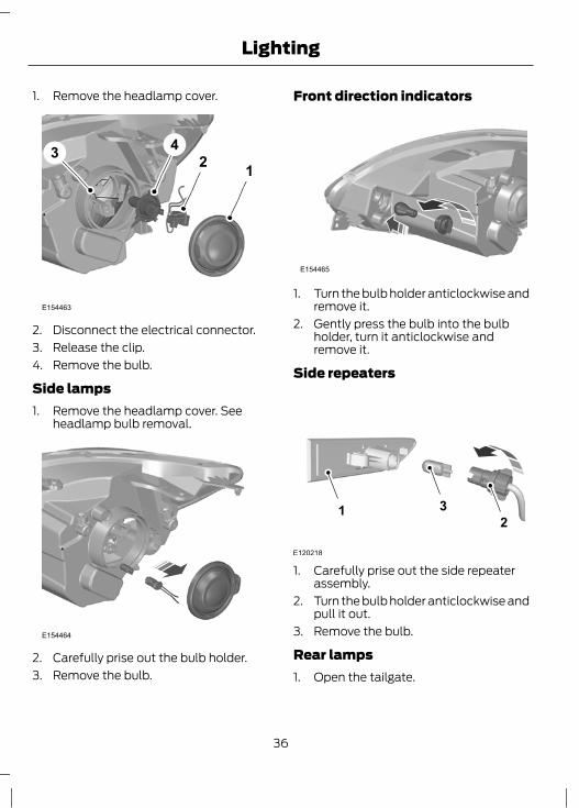
DIRECTION INDICATORS
E102191
Move the lever up/down to activateright/left direction indicators respectively.During lane changing flick the lever up ordown and the direction indicators will flashthree times.Sudden increase in the rate of flashingwarns a failed indicator bulb.
INTERIOR LAMPSCourtesy lamp
E120292
ACB
OffADoor contactBOnC
If you set the switch to position A, thecourtesy lamp will be off irrespective ofthe doors being opened or closed.If you set the switch to position B thecourtesy lamp turns on during thefollowing conditions.
High variantMid variantBase variant
Illuminates1Illuminates1
Does not illuminate
Any of the 4 dooropen
IlluminatesDoes not illuminateLuggage compart-ment open
1 - The illumination will have theatre dimming effect.
If you set the switch to position C, thecourtesy lamp will come on irrespective ofthe door condition and ignition switchposition. It will go off automatically aftera short time to prevent the vehicle batteryfrom discharging. To switch it back on,switch on the ignition for a short time.
34
Lighting
Luggage compartment lamp
E120328
The luggage compartment lamp turns onduring the following conditions.
High variantMid variantBase variant
IlluminatesNo Luggagecompartment lamp
fitted
No Luggagecompartment lamp
fitted
Any of the 4 dooropen
IlluminatesLuggage compart-ment open
CHANGING A BULB
WARNINGSSwitch the lights and the ignition off.
Let the bulb cool down beforeremoving it.
CAUTIONSDo not touch the glass of the bulb.
Only fit bulbs of the correctspecification. See BulbSpecification Chart (page 38).
Note: The following instructions describehow to remove the bulbs. Fitting is thereverse order unless otherwise stated.
Headlamp main and dipped beamNote: To remove the right hand sideheadlamp bulb, detach the coolantreservoir.Detach the coolant reservoir
E125296
2
1
1. Remove the bolt.2. Pull the container from the bracket.Headlamp bulb
35
Lighting
1. Remove the headlamp cover.
1243
E154463
2. Disconnect the electrical connector.3. Release the clip.4. Remove the bulb.
Side lamps1. Remove the headlamp cover. See
headlamp bulb removal.
E154464
2. Carefully prise out the bulb holder.3. Remove the bulb.
Front direction indicators
E154465
1. Turn the bulb holder anticlockwise andremove it.
2. Gently press the bulb into the bulbholder, turn it anticlockwise andremove it.
Side repeaters
E120218
12
3
1. Carefully prise out the side repeaterassembly.
2. Turn the bulb holder anticlockwise andpull it out.
3. Remove the bulb.
Rear lamps1. Open the tailgate.
36
Lighting

E154483
2. Unscrew the screws and remove therear lamp assembly.
3. Gently press the bulbs into the bulbholder, turn them anticlockwise andremove them.
A
BC
E154484
Parking/Brake bulbATurn signal bulbBReverse lamp bulbC
Central high mounted stop lamp
2 3
E154784
4
1. Open the tailgate.2. Remove the rubber grommet.3. Release the clips using a flat-bladed
screwdriver, remove the lamp anddisconnect the connector.
4. Unclip the bulb holder and remove thebulb.
37
Lighting
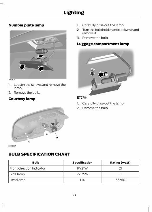
Number plate lamp
E90601
1. Loosen the screws and remove thelamp.
2. Remove the bulb.
Courtesy lamp
E120231
12
3
1. Carefully prise out the lamp.2. Turn the bulb holder anticlockwise and
remove it.3. Remove the bulb.
Luggage compartment lamp
E72784
1. Carefully prise out the lamp.2. Remove the bulb.
BULB SPECIFICATION CHART
Rating (watt)SpecificationBulb
21PY21WFront direction indicator
5P21/5WSide lamp
55/60H4Headlamp
38
Lighting

Rating (watt)SpecificationBulb
5WYW5Side repeater
55H11Front fog lamp
5P21/5WBrake and parking lamp (rear)
21P21WRear direction indicator
21P21WReversing lamp and rear fog lamp
16W16WCentral high mounted stop lamp
5CW5Number plate lamp
6W6WCourtesy lamp
5W6WLuggage compartment lamp
39
Lighting

POWER WINDOWS
WARNINGDo not operate the electric windowsunless they are free from obstruction.
Note: If you operate the switches oftenduring a short period of time, the systemmight become inoperable for a certain timeto prevent damage due to overheating.The power windows can be operated onlywhen the ignition is switched on.The front power window can be operatedby the switches located on either of thedoor trims (driver door and front passengerdoor). To lower or raise the window, pressor pull the power window switchrespectively.
E120219
Manual windows
E120310
To raise/lower the window rotate thehandle.Note: The rear window cannot be fullylowered.
EXTERIOR MIRRORSFolding mirrors
E102162
You can fold back your exterior mirror innarrow spaces or when the vehicle isparked to avoid accidental damage to themirrors.Make sure that you fully engage the mirrorin its support when returning it to itsoriginal position.
40
Windows and Mirrors
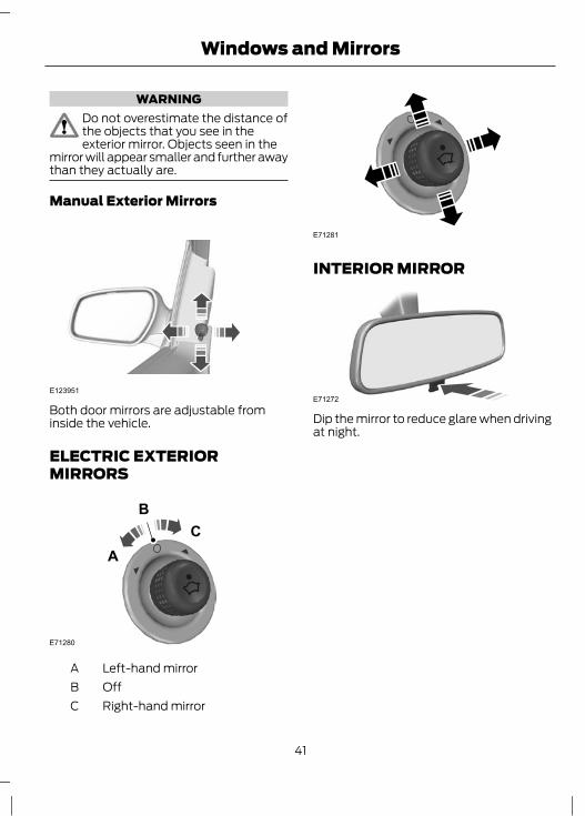
WARNINGDo not overestimate the distance ofthe objects that you see in theexterior mirror. Objects seen in the
mirror will appear smaller and further awaythan they actually are.
Manual Exterior Mirrors
E123951
Both door mirrors are adjustable frominside the vehicle.
ELECTRIC EXTERIORMIRRORS
E71280
BC
A
Left-hand mirrorAOffBRight-hand mirrorC
E71281
INTERIOR MIRROR
E71272
Dip the mirror to reduce glare when drivingat night.
41
Windows and Mirrors
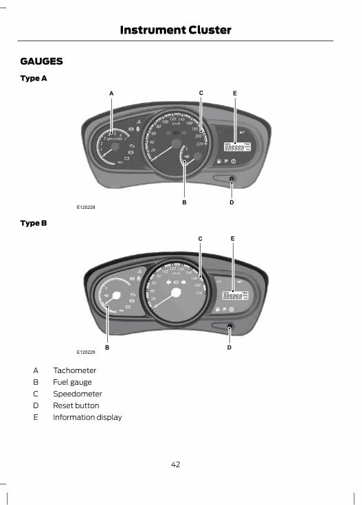
GAUGESType A
C
B D
A E
E120228
Type B
E120229
C
B D
E
TachometerAFuel gaugeBSpeedometerCReset buttonDInformation displayE
42
Instrument Cluster
Theater dimmingThe instrument cluster illuminatesgradually with a theater dimming effectwhen the side lamps are switched on.
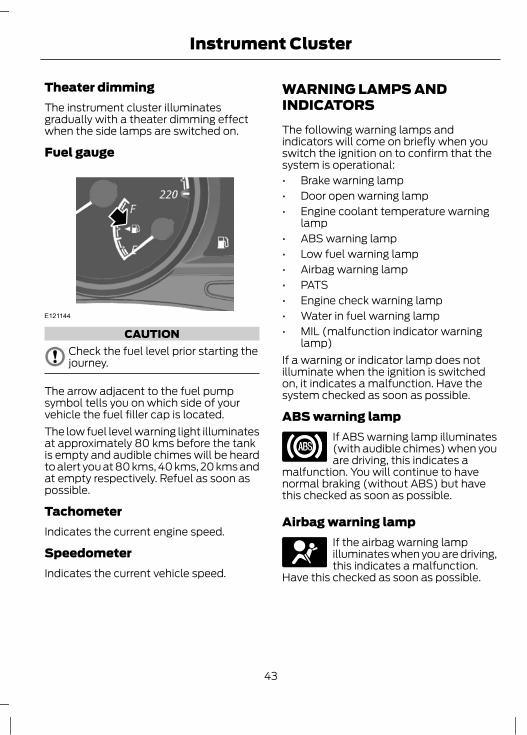
Fuel gauge
E121144
CAUTIONCheck the fuel level prior starting thejourney.
The arrow adjacent to the fuel pumpsymbol tells you on which side of yourvehicle the fuel filler cap is located.The low fuel level warning light illuminatesat approximately 80 kms before the tankis empty and audible chimes will be heardto alert you at 80 kms, 40 kms, 20 kms andat empty respectively. Refuel as soon aspossible.
TachometerIndicates the current engine speed.
SpeedometerIndicates the current vehicle speed.
WARNING LAMPS ANDINDICATORSThe following warning lamps andindicators will come on briefly when youswitch the ignition on to confirm that thesystem is operational:• Brake warning lamp• Door open warning lamp• Engine coolant temperature warning
lamp• ABS warning lamp• Low fuel warning lamp• Airbag warning lamp• PATS• Engine check warning lamp• Water in fuel warning lamp• MIL (malfunction indicator warning
lamp)If a warning or indicator lamp does notilluminate when the ignition is switchedon, it indicates a malfunction. Have thesystem checked as soon as possible.
ABS warning lampIf ABS warning lamp illuminates(with audible chimes) when youare driving, this indicates a
malfunction. You will continue to havenormal braking (without ABS) but havethis checked as soon as possible.
Airbag warning lampIf the airbag warning lampilluminates when you are driving,this indicates a malfunction.
Have this checked as soon as possible.
43
Instrument Cluster
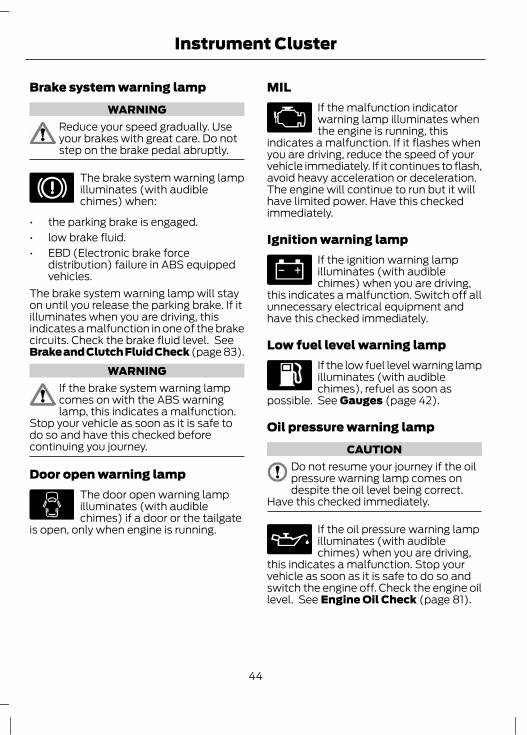
Brake system warning lampWARNING
Reduce your speed gradually. Useyour brakes with great care. Do notstep on the brake pedal abruptly.
The brake system warning lampilluminates (with audiblechimes) when:
• the parking brake is engaged.• low brake fluid.• EBD (Electronic brake force
distribution) failure in ABS equippedvehicles.
The brake system warning lamp will stayon until you release the parking brake. If itilluminates when you are driving, thisindicates a malfunction in one of the brakecircuits. Check the brake fluid level. SeeBrake and Clutch Fluid Check (page 83).
WARNINGIf the brake system warning lampcomes on with the ABS warninglamp, this indicates a malfunction.
Stop your vehicle as soon as it is safe todo so and have this checked beforecontinuing you journey.
Door open warning lampThe door open warning lampilluminates (with audiblechimes) if a door or the tailgate
is open, only when engine is running.
MILIf the malfunction indicatorwarning lamp illuminates whenthe engine is running, this
indicates a malfunction. If it flashes whenyou are driving, reduce the speed of yourvehicle immediately. If it continues to flash,avoid heavy acceleration or deceleration.The engine will continue to run but it willhave limited power. Have this checkedimmediately.
Ignition warning lampIf the ignition warning lampilluminates (with audiblechimes) when you are driving,
this indicates a malfunction. Switch off allunnecessary electrical equipment andhave this checked immediately.
Low fuel level warning lampIf the low fuel level warning lampilluminates (with audiblechimes), refuel as soon as
possible. See Gauges (page 42).
Oil pressure warning lampCAUTION
Do not resume your journey if the oilpressure warning lamp comes ondespite the oil level being correct.
Have this checked immediately.
If the oil pressure warning lampilluminates (with audiblechimes) when you are driving,
this indicates a malfunction. Stop yourvehicle as soon as it is safe to do so andswitch the engine off. Check the engine oillevel. See Engine Oil Check (page 81).
44
Instrument Cluster
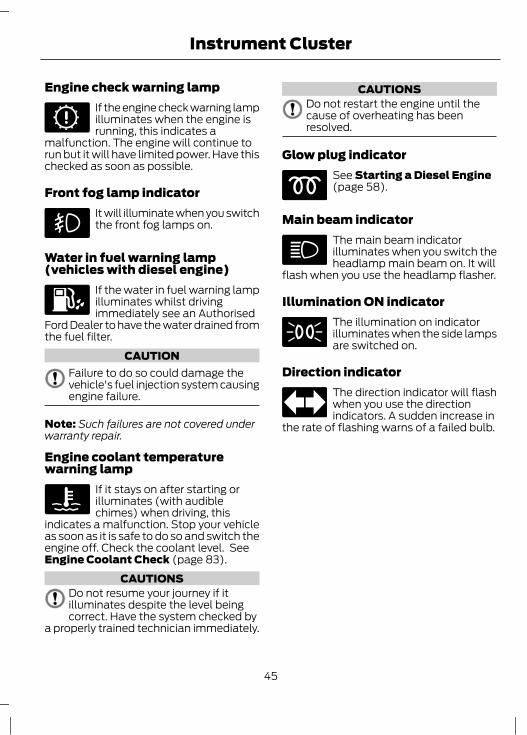
Engine check warning lampIf the engine check warning lampilluminates when the engine isrunning, this indicates a
malfunction. The engine will continue torun but it will have limited power. Have thischecked as soon as possible.
Front fog lamp indicatorIt will illuminate when you switchthe front fog lamps on.
Water in fuel warning lamp(vehicles with diesel engine)
If the water in fuel warning lampilluminates whilst drivingimmediately see an Authorised
Ford Dealer to have the water drained fromthe fuel filter.
CAUTIONFailure to do so could damage thevehicle's fuel injection system causingengine failure.
Note: Such failures are not covered underwarranty repair.
Engine coolant temperaturewarning lamp
If it stays on after starting orilluminates (with audiblechimes) when driving, this
indicates a malfunction. Stop your vehicleas soon as it is safe to do so and switch theengine off. Check the coolant level. SeeEngine Coolant Check (page 83).
CAUTIONSDo not resume your journey if itilluminates despite the level beingcorrect. Have the system checked by
a properly trained technician immediately.
CAUTIONSDo not restart the engine until thecause of overheating has beenresolved.
Glow plug indicatorSee Starting a Diesel Engine(page 58).
Main beam indicatorThe main beam indicatorilluminates when you switch theheadlamp main beam on. It will
flash when you use the headlamp flasher.
Illumination ON indicatorThe illumination on indicatorilluminates when the side lampsare switched on.
Direction indicatorThe direction indicator will flashwhen you use the directionindicators. A sudden increase in
the rate of flashing warns of a failed bulb.
45
Instrument Cluster

GENERAL INFORMATION
WARNINGDo not operate the informationdisplay controls when the vehicle ismoving. The driver should at all times
be alert and focus his attention on the roadahead only.
Note: The information display will remainon for several minutes after you switch offthe ignition.
Information display
E120230
C
D
B
A
OdometerATripmeterBDistance to emptyCReset buttonD
Press the reset button to scroll through thedisplays.Note: The information display illuminateswhen the driver door is opened.
Display definitionsTripmeterNote: The maximum value for tripmeter is9999.9kms and after that it automaticallyresets and starts from zero.
The tripmeter can register the mileage ofindividual journeys.
Distance to emptyIndicates the approximate distance thatyour vehicle will travel on the fuel in thefuel tank.Distance to empty display will stay on forapproximately 5 seconds when the igntionis switched on and then cluster will go backto the pre-set mode.
OdometerNote: The maximum value for odometermeasurement is 999,999 kms after that itautomatically resets and starts from zero.Registers the total mileage of the vehicle.
Reset buttonA short press toggles the display betweenodometer/trip/distance to empty.A long press of more than two secondsresets the trip to zero.
46
Information Displays

PRINCIPLE OF OPERATIONOutside airIn this mode the climate control systemutilizes outside air.
Cowl filter and wire mesh filterThese filters remove the dust that isbrought in from the outside air through thecooling and heating system, when theblower is operated.Have your dealer replace/clean the filtersas mentioned in the Periodicalmaintenance schedule.
Recirculated airCAUTION
Prolonged use of recirculated air maycause the windows to mist up. If thewindows mist up, follow the settings
for defrosting and demisting thewindscreen.
The air currently in the passengercompartment will be recirculated. Outsideair will not enter the vehicle.Ensure maximum utilization of therecirculation mode to avoid dust enteringinto the passenger compartment and badsmell entering from outside.
HeatingThe purpose of heating is to heat theinterior compartment in cold weatherconditions.Heating performance depends on thetemperature of the engine coolant.
Air conditioningThe purpose of air conditioning is to coolthe interior compartment.
Air is directed through the evaporatorwhere it is cooled. Humidity is extractedfrom the air to help keep the windows freeof mist. The resulting condensation isdirected to the outside of the vehicle andit is therefore normal if you see a smallpool of water under your vehicle.If you use the air conditioning, the fuelconsumption of your vehicle will be higher.Note: The air conditioning operates onlywhen the temperature is above 4ºC (39ºF).
General information on controllingthe interior climateWarming the interiorDirect the air towards your feet. In cold orhumid weather conditions, direct some ofthe air towards the windscreen and thedoor windows.
Cooling the interiorDirect the air towards your face.
AIR VENTS
E71942
47
Climate Control
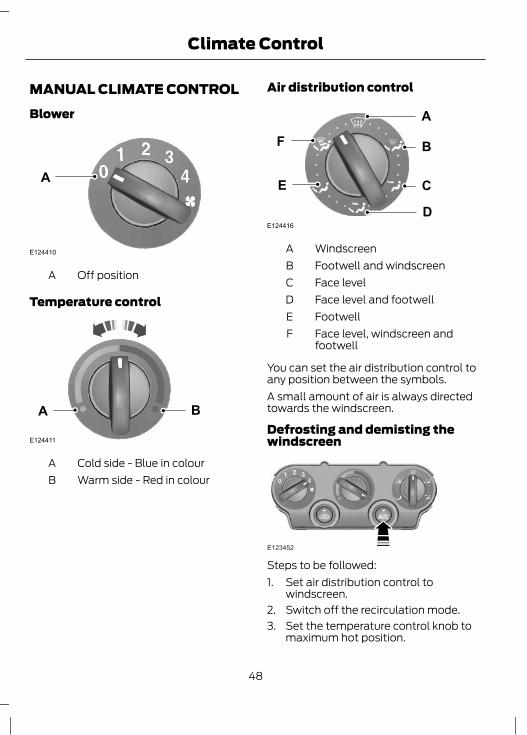
MANUAL CLIMATE CONTROLBlower
E124410
A
Off positionA
Temperature control
E124411
A B
Cold side - Blue in colourAWarm side - Red in colourB
Air distribution control
E124416
A
B
C
D
F
E
WindscreenAFootwell and windscreenBFace levelCFace level and footwellDFootwellEFace level, windscreen andfootwell
F
You can set the air distribution control toany position between the symbols.A small amount of air is always directedtowards the windscreen.
Defrosting and demisting thewindscreen
E123452
Steps to be followed:1. Set air distribution control to
windscreen.2. Switch off the recirculation mode.3. Set the temperature control knob to
maximum hot position.
48
Climate Control
4. Set the blower to maximum speed.5. Switch on the A/C.If necessary, switch the heated windowson in the instrument panel. See HeatedWindows (page 50).
E72507
VentilationThere are two types of ventilation.Normal ventilationUse outside/fresh air mode. Air will flowfrom outside through the air vents duringdriving with the blower in off position. Theair distribution control mode can be at anydesired position.Forced ventilationIn this type of ventilation the blower canbe positioned at any speed and the restare same as normal ventilation.
Switching the air conditioning onand off
E124402
Press the button, to switch on/off the A/C.If you turn the blower off, the airconditioning will turn off. When you turnthe blower on again, the air conditioningwill come on automatically (if the A/Cswitch is in on position).
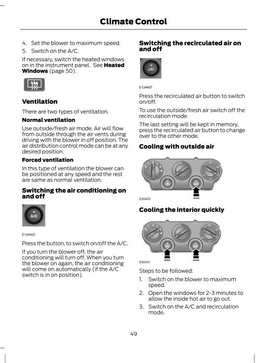
Switching the recirculated air onand off
E124407
Press the recirculated air button to switchon/off.To use the outside/fresh air switch off therecirculation mode.The last setting will be kept in memory,press the recirculated air button to changeover to the other mode.
Cooling with outside air
E90450
Cooling the interior quickly
E90451
Steps to be followed:1. Switch on the blower to maximum
speed.2. Open the windows for 2-3 minutes to
allow the inside hot air to go out.3. Switch on the A/C and recirculation
mode.
49
Climate Control
4. Set the temperature control knob tomaximum cold position.
5. Close the windows and set the blowerto 2nd speed or to your convenience.
Heating the interior quickly
E90449
Reducing interior air humidity
E90452
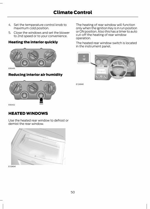
HEATED WINDOWSUse the heated rear window to defrost ordemist the rear window.
E124041
The heating of rear window will functiononly when the ignition Key is in run positionor ON position. Also this has a timer to autocut-off the heating of rear windowoperation.The heated rear window switch is locatedin the instrument panel.
E124040
50
Climate Control

SITTING IN THE CORRECTPOSITION
E68595
WARNINGSDo not adjust the seats when thevehicle is moving.Only when you use the seat beltproperly, can it hold you in a positionthat allows the airbag to achieve its
optimum effect.
When you use them properly, the seat,head restraint, seat belt and airbags willprovide optimum protection in the eventof a collision. We recommend that you:• sit in an upright position with the base
of your spine as far back as possible.• do not recline the seatback more than
30 degrees.• adjust the head restraint so that the
top of it is level with the top of yourhead and as far forwards as possible,remaining comfortable.
• keep sufficient distance betweenyourself and the steering wheel. Werecommend a minimum of 250millimetres (10 inches) between yourbreastbone and the airbag cover.
• hold the steering wheel with your armsslightly bent.
• bend your legs slightly so that you canpress the pedals fully.
• position the shoulder strap of the seatbelt over the centre of your shoulderand position the lap strap tightly acrossyour hips.
Make sure that your driving position iscomfortable and that you can maintain fullcontrol of your vehicle.
MANUAL SEATSMoving the seats backwards andforwards
2
2
1
E102370
Raise the lever to unlock the seatfrom track
1
Seat forward and rearwardmovement
2
51
Seats
WARNINGRock the seat backwards andforwards after releasing the lever tomake sure that it is fully engaged in
its catch.
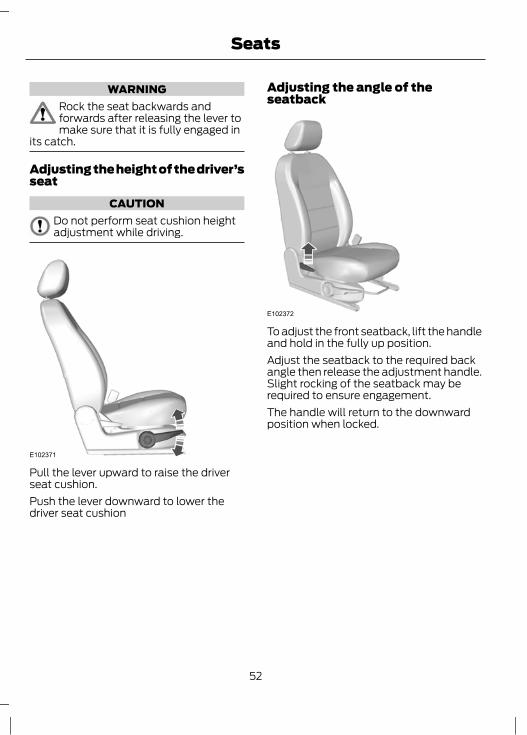
Adjusting the height of the driver’sseat
CAUTIONDo not perform seat cushion heightadjustment while driving.
E102371
Pull the lever upward to raise the driverseat cushion.Push the lever downward to lower thedriver seat cushion
Adjusting the angle of theseatback
E102372
To adjust the front seatback, lift the handleand hold in the fully up position.Adjust the seatback to the required backangle then release the adjustment handle.Slight rocking of the seatback may berequired to ensure engagement.The handle will return to the downwardposition when locked.
52
Seats

HEAD RESTRAINTS
E75767
Adjusting the head restraintAdjust the head restraint so that the topof it is level with the top of your head.
Removing the head restraintPress the locking buttons and remove thehead restraint.
REAR SEATS
WARNINGMake sure that the seats and theseatbacks are secured and fullyengaged in their catches.
Folding the seatbacks downWARNING
When folding the seatbacks down,take care not to get your fingerscaught between the seatback and
seat frame.
E123947
1
1
2
1. Push the unlock levers.2. Push the seatback forwards.
Creating a level load floorWARNING
Make sure the red indicator is notshowing when you engage the seatin the catches.
53
Seats
E123948
2
1
2
3
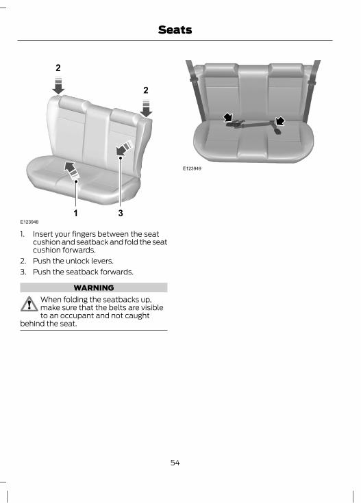
1. Insert your fingers between the seatcushion and seatback and fold the seatcushion forwards.
2. Push the unlock levers.3. Push the seatback forwards.
WARNINGWhen folding the seatbacks up,make sure that the belts are visibleto an occupant and not caught
behind the seat.
E123949
54
Seats
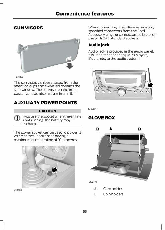
SUN VISORS
E66493
The sun visors can be released from theretention clips and swivelled towards theside window. The sun visor on the frontpassenger side also has a mirror in it.
AUXILIARY POWER POINTS
CAUTIONIf you use the socket when the engineis not running, the battery maydischarge.
The power socket can be used to power 12volt electrical appliances having amaximum current rating of 10 amperes.
E120275
When connecting to appliances, use onlyspecified connectors from the FordAccessory range or connectors suitable foruse with SAE standard sockets.
Audio jackAudio jack is provided in the audio panel.It is used for connecting MP3 players,iPod's, etc, to the audio system.
E122031
GLOVE BOX
A B
E102199
B
Card holderACoin holdersB
55
Convenience features

Note: Do not store heavy and bulky itemsin the glove box as it may lead to failure ofthe glove box securing lock.
USB PORTThe USB port is located inside the glovebox.
56
Convenience features

GENERAL INFORMATIONGeneral points on startingIf the battery has been disconnected thevehicle may exhibit some unusual drivingcharacteristics for approx. 8 kilometres (5miles) after reconnecting the battery.This is because the engine managementsystem must realign itself with the engine.Any unusual driving characteristics duringthis period may be disregarded.The starter should not be operated forlonger than 10 seconds during each startcycle. Release the ignition key as soon asthe engine has started. If the engine hasnot started, return the ignition key toposition O and repeat the startingprocedure.If the engine does not start, See FuelCut-Off Switch (page 68).
Starting the engine by towing orpushing
WARNINGTo prevent damage you must notpush or tow start your vehicle. Usebooster cables and a booster battery.
See Jump-Starting the Vehicle (page90).
IGNITION SWITCHIgnition switch positionsPosition 0
WARNINGNever return the key to the 0 positionwhen the vehicle is in motion.
Ignition off. When the key is removed fromthe ignition switch, the steering columnlock will be activated as soon as thesteering wheel is turned.
Position ISteering unlocked. Ignition and all mainelectrical circuits are disabled. The ignitionkey should not be left in this position fortoo long to avoid discharging the battery.
Positon IIIgnition switched on, all electrical circuitsoperational. Warning and indicator lampsilluminate. This is the key position whendriving, and must also be selected whenbeing towed.
Postion IIIStarter motor activated. Release the keyas soon as the engine starts.
STARTING A PETROL ENGINENote: You can only operate the starter fora maximum of 10 seconds at a time.
Cold or hot engineAll vehicles
CAUTIONWhen the temperature is below -10ºC,switch the ignition on for at least onesecond before starting the engine.
This will make sure that the maximum fuelpressure is established for starting theengine.
Note: Do not touch the accelerator pedal.1. Fully depress the clutch pedal.2. Start the engine.
57
Starting and Stopping the Engine

If the engine does not start within 10seconds, wait for a short period and tryagain.If the engine does not start after threeattempts, wait 10 seconds and follow theFlooded engine procedure.If you have difficulty starting the enginewhen the temperature is below -10ºC,press the accelerator pedal between ¼ to½ of its travel and try again.
Flooded engine1. Fully depress the clutch pedal.2. Fully depress the accelerator pedal and
hold it there.3. Start the engine.If the engine does not start, repeat theCold or hot engine procedure.
Engine idle speed after startingThe speed at which the engine idlesimmediately after starting will varydepending on the engine temperature.If the engine is cold then the idle speed willautomatically be increased.The idle speed will slowly decrease to thenormal level as the engine warms up.
STARTING A DIESEL ENGINECold or hot engineNote: When the temperature is below-10ºC, you may need to crank the engine forup to 10 seconds. To aid ease of cranking,turn the ignition key to position II for at leastcouple of seconds before starting theengine. This ensures that maximum fuelpressure is established.Note: Continue cranking the engine until itstarts.Note: You can only operate the starter fora maximum of 10 seconds at a time.
Switch the ignition on and waituntil the glow plug indicator goesoff.
Note: Do not touch the accelerator pedal.1. Fully depress the clutch pedal.2. Start the engine.3. Repeat this exercise for 3 to 4 times
until the engine cranks properly.Note: If starting difficulty is experienced attemperatures below -10ºC, depress theaccelerator pedal 1/4 to ½ of its travel toassist starting. This should be done only, ifthe engine fails to start after severalattempts of cranking as given in the abovesteps.
Flooded EngineNote: Do not depress the accelerator pedalfully.1. Depress the clutch pedal fully.2. Slowly, depress the accelerator fully,
hold it in this position and start theengine.
3. If the engine does not start repeat thisexercise for 3 to 4 times.
SWITCHING OFF THE ENGINEVehicles with a turbocharger
CAUTIONDo not switch the engine off when itis running at high speed. If you do, theturbocharger will continue running
after the engine oil pressure has droppedto zero. This will lead to prematureturbocharger bearing wear.
Release the accelerator pedal. Wait untilthe engine has reached idle speed and thenswitch it off.
58
Starting and Stopping the Engine
SAFETY PRECAUTIONS
WARNINGSStop refuelling after the fuel nozzlestops the second time. Additionalfuel will fill the expansion space in
the fuel tank which could lead to fueloverflowing. Fuel spillage could behazardous to other road users.
Do not use any kind of flames or heatnear the fuel system. The fuel systemis under pressure. There is a risk of
injury if the fuel system is leaking.
CATALYTIC CONVERTER
WARNINGDo not park or idle your vehicle overdry leaves, dry grass or othercombustible materials. The exhaust
will radiate a considerable amount of heatduring use, and after you have switchedthe engine off. This is a potential firehazard.
Driving with a catalytic converterCAUTIONS
Avoid running out of fuel.
Do not crank the engine for longperiods.Do not run the engine when a sparkplug lead is disconnected.Do not push-start or tow-start yourvehicle. Use booster cables. SeeJump-Starting the Vehicle (page
90).Do not switch the ignition off whendriving.
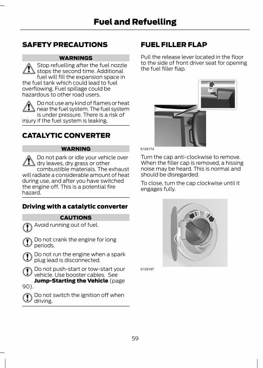
FUEL FILLER FLAPPull the release lever located in the floorto the side of front driver seat for openingthe fuel filler flap.
E120174
Turn the cap anti-clockwise to remove.When the filler cap is removed, a hissingnoise may be heard. This is normal andshould be disregarded.To close, turn the cap clockwise until itengages fully.
E120197
59
Fuel and Refuelling
REFUELLING
CAUTIONDo not attempt to start the engine ifyou have filled the fuel tank with theincorrect fuel. This could damage the
engine. Have the system checked by aproperly trained technician immediately.
FUEL QUALITY - PETROLNote: Add 1 ml of IFTEX System G withevery litre of Gasoline (Petrol). It is availableat all Ford authorised dealerships.
CAUTIONDo not use leaded petrol or petrol withadditives containing other metalliccompounds (e.g. manganese-based).
They could damage the emission system.
Use minimum 91 octane unleaded petrolthat meets the specification defined by EN228, or equivalent.
FUEL QUALITY - DIESELNote: We recommend that you use onlyhigh quality fuel without additives or otherengine treatments.
WARNINGDo not mix diesel with oil, petrol orother liquids. This could cause achemical reaction.
CAUTIONDo not add kerosene, paraffin orpetrol to diesel. This could causedamage to the fuel system.
Use diesel that meets the specificationdefined by EN 590, or equivalent.
You can use diesel that contains up to 5%RME (bio diesel).Prolonged use of supplemental additivesto prevent fuel waxing is notrecommended.
FUEL CONSUMPTIONLength of journey/enginetemperatureFrequent cold starts and short distancedriving leads to considerably increased fuelusage.
Traffic and road conditionsSlow moving traffic, uphill driving, frequentsharp bends and rough roads all have anadverse effect on fuel consumption.
Erratic driving habitsAnticipate hazards ahead and keep a safedistance from the vehicle in front.This not only reduces fuel consumptionbut also the noise level.If you have a prolonged wait at a railwaycrossing or at traffic lights in built-up areas,it is advisable to switch off the engineduring this period.
Vehicle load conditionsDriving in a fully laden condition will resultin high fuel consumption.
Vehicle conditionLow tyre pressure or inadequate engine orvehicle maintenance will also result inhigher fuel consumption.
60
Fuel and Refuelling

MANUAL TRANSMISSION
WARNINGSEngage reverse gear only when thevehicle is stationary.Do not apply any undue lateral forceto the gear lever when changing from5th to 4th gear as this could lead to
the inadvertent selection of 2nd gear.
Reverse gear
E99077
Note: The reverse gear should be engagedonly when the vehicle is stationary.To avoid shi�ing noises when engaging thereverse gear, wait approximately threeseconds with the clutch depressed whenthe vehicle is stationary.
To select the reverse gear, shi� the leverinto the neutral position and then press thelever fully to the right against a springpressure, before pulling rearwards.
61
Transmission
Driving speed and gear selection1.2L Petrol
Engine RPMrange
Speed rangeGear
800-20000-151
1100-225015-302
1500-225030-453
1700-225045-604
>1750>605
1.4L Diesel
Engine RPMrange
Speed rangeGear
750-17500-151
1000-200015-302
1400-200030-453
1500-200045-604
>1750>605

PRINCIPLE OF OPERATIONDual circuit braking system
E71353
WARNINGIf a brake circuit fails, you will at firstexperience a softer feel to the brakepedal. You will then need to exert a
greater force on the brake pedal, and makeallowances for increased stoppingdistances. Have the braking systemchecked by an expert before continuingyour journey. Authorised Ford Dealers arerecommended.
Your vehicle is fitted with a diagonally split,dual circuit brake system. If a brake circuitfails, the other remains operational.
Disc brakes
E71354
Wet brake discs result in reduced brakingefficiency. Dab the brake pedal whendriving from a car wash to remove the filmof water.
After leaving a car wash or driving thevehicle through water, dab the brake pedalwhile driving to remove the film of water.
ABSWARNING
The ABS does not relieve you of yourresponsibility to drive with due careand attention.
The ABS helps you to maintain full steeringand directional stability when you brakeheavily in an emergency, by preventing theroad wheels from locking.
HINTS ON DRIVING WITHANTI-LOCK BRAKES
E71355
When the ABS is operating, the brake pedalwill pulse. This is normal. Maintain pressureon the brake pedal.The ABS will not eliminate the dangersinherent when:• you drive too close to the vehicle in
front of you.• the vehicle is aquaplaning.• you take corners too fast.• the road surface is poor.
62
Brakes
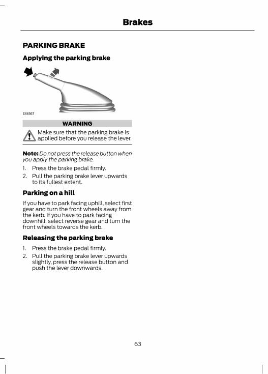
PARKING BRAKEApplying the parking brake
E66567
WARNINGMake sure that the parking brake isapplied before you release the lever.
Note: Do not press the release button whenyou apply the parking brake.1. Press the brake pedal firmly.2. Pull the parking brake lever upwards
to its fullest extent.
Parking on a hillIf you have to park facing uphill, select firstgear and turn the front wheels away fromthe kerb. If you have to park facingdownhill, select reverse gear and turn thefront wheels towards the kerb.
Releasing the parking brake1. Press the brake pedal firmly.2. Pull the parking brake lever upwards
slightly, press the release button andpush the lever downwards.
63
Brakes
PRINCIPLE OF OPERATIONEngine speed limiterThe engine speed is limited electronicallyto protect the engine.
64
Automatic speed limiter (ASL)

GENERAL INFORMATION
WARNINGSUse load securing straps to anapproved standard, e.g. DIN.Make sure that you secure all looseitems properly.Place luggage and other loads as lowand as far forward as possible withinthe luggage or loadspace.Do not drive with the tailgate or reardoor open. Exhaust fumes may enterthe vehicle.Do not exceed the maximum frontand rear axle loads for your vehicle.
CAUTIONSDo not allow items to contact the rearwindows.Do not use any abrasive materials toclean the interior of the rear windows.Do not install stickers or labels to theinterior of the rear windows.
LUGGAGE COVERS
CAUTIONDo not place objects on the luggagecover.
1
2E72512
65
Load Carrying

GENERAL DRIVING POINTSVehicles with a diesel engineIf the low fuel level warning lamp comeson, refuel as soon as possible. If youcontinue driving without refuelling, theengine will start to run unevenly. Thisindicates that you are about to run out offuel. Refuel immediately.
RUNNING-INTyres
WARNINGNew tyres need to be run-in forapproximately 500 kilometres (300miles). During this time, you may
experience different driving characteristics.
Brakes and clutchWARNING
Avoid heavy use of the brakes andclutch if possible for the first 150kilometres (100 miles) in town and
for the first 1500 kilometres (1000 miles)on motorways.
EngineCAUTION
Avoid driving too fast during the first1500 kilometres (1000 miles). Varyyour speed frequently and change up
through the gears early. Do not labour theengine.
DRIVING THROUGH WATERDriving through water
CAUTIONSDrive through water in an emergencyonly, and not as part of normal driving.Engine damage can occur if waterenters the air filter.
In an emergency, the vehicle can be driventhrough water to a maximum depth of 200millimetres (8 inches) and at a maximumspeed of 10 km/h (6 mph). Extra cautionshould be exercised when driving throughflowing water.When driving in water, maintain a lowspeed and do not stop the vehicle. Afterdriving through water, and as soon as it issafe to do so:• Depress the brake pedal lightly and
check that full brake function isachieved.
• Check that the horn works.• Check that the vehicle's lights are fully
operational.• Check the power assistance
of the steering system.
66
Driving Hints

FIRST AID KIT
E102206
First aid kit is stored in the glove box. Itcontains spare fuses, spare bulbs andemergency medical treatment kit. Use itunder emergency situations.
WARNING TRIANGLESpace is provided in the spare wheel wellto store a warning triangle.
67
Roadside Emergencies
INSPECTING SAFETY SYSTEMCOMPONENTSSeat beltsBelts subjected to strain, as a result of anaccident, should be renewed and theanchorages checked by a properly trainedtechnician.
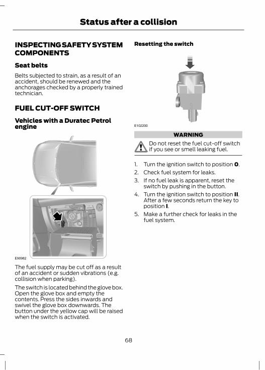
FUEL CUT-OFF SWITCHVehicles with a Duratec Petrolengine
E90982
The fuel supply may be cut off as a resultof an accident or sudden vibrations (e.g.collision when parking).The switch is located behind the glove box.Open the glove box and empty thecontents. Press the sides inwards andswivel the glove box downwards. Thebutton under the yellow cap will be raisedwhen the switch is activated.
Resetting the switch
E102200
WARNINGDo not reset the fuel cut-off switchif you see or smell leaking fuel.
1. Turn the ignition switch to position 0.2. Check fuel system for leaks.3. If no fuel leak is apparent, reset the
switch by pushing in the button.4. Turn the ignition switch to position II.
After a few seconds return the key toposition I.
5. Make a further check for leaks in thefuel system.
68
Status after a collision
CHANGING A FUSE
WARNINGSDo not modify the electrical systemof your vehicle in any way. Haverepairs to the electrical system and
the replacement of relays and high currentfuses carried out by a Ford authorizeddealer personnel.
Switch the ignition and all electricalequipment off before touching orattempting to change a fuse.
CAUTIONFit a replacement fuse with the samerating as the one you have removed.
Note: You can identify a blown fuse by abreak in the filament.Note: All fuses, except high current fuses,are a push fit.
E102376
Fuse puller is available in the First aid kit.Remove the fuses using fuse puller only.
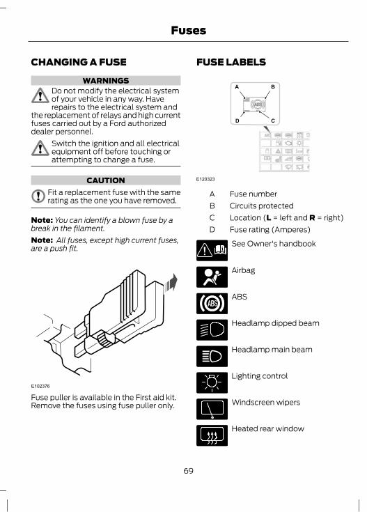
FUSE LABELS
E120323
A B
CD
Fuse numberACircuits protectedBLocation (L = left and R = right)CFuse rating (Amperes)D
See Owner's handbook
Airbag
ABS
Headlamp dipped beam
Headlamp main beam
Lighting control
Windscreen wipers
Heated rear window
69
Fuses

Blower motor
Air conditioning
Horn
Engine management orelectronic module
Fuel pump
Battery and charging system
Instrument cluster, battery saver,number plate lamp.
Side and tail lamps
Central locking
Hazard warning flashers anddirection indicators
Ignition
Brake lamps
Reversing lamp
FUSE SPECIFICATION CHARTEngine junction box
E120757
Circuits protectedAmpereratingFuse
Not used-F1
Not used-F2
Diesel glow plug relay60F3
Cooling fan and AC (Duratec - Petrol)40F4
Cooling fan and AC (Duratorq - Diesel)50
PJB busbar BB160F5
70
Fuses

Circuits protectedAmpereratingFuse
Ignition Relay60F6
PJB busbar BB460F7
PJB busbar BB560F8
Passenger junction box
E122292
71
Fuses

Circuits protectedAmpere ratingFuse
Not used-F1
Not used-F2
Not used-F3
Air conditioning clutch10F4
ABS valve20F5
Power mirrors7.5F6
Electric decklid release10F7
Not used-F8
Head lamp low (dipped) beam - LHS10F9
Head lamp low (dipped) beam - RHS10F10
Not Used-F11
Powertrain control module fuse15F12
Heated oxygen sensor - Petrol20F13
Powertrain control module - Diesel
Not used-F14
Fuel pump20F15
Powertrain control module power3F16
Lighting switch15F17
Onboard diagnotics/radio15F18
Not used-F19
Instrument cluster7.5F20
Not used-F21
Park/tail lamp - LHS7.5F22
Park/tail lamp - RHS7.5F23
Power door locks (BFC)20F24
Turn/hazard lamp15F25
72
Fuses
Circuits protectedAmpere ratingFuse
Heated back window20F26
Horn15F27
Alternator3F28
Front power outlet connector20F29
Ignition switch15F30
Cargo/dome Lamp7.5F31
Driver door unlock power (BFC)10F32
License plate lamp7.5F33
Rear window heater switch3F34
Not used-F35
Turn/hazard flasher10F36
ABS module3F37
HVAC control panel/Thermistor assy/BFC7.5F38
Air bag module7.5F39
Light/dimmer switch10F40
Instrument cluster7.5F41
Not used-F42
Not used-F43
Radio/Instrument cluster3F44
Stop lamps15F45
Front wiper20F46
Rear wiper park position10F47
Back up lamp7.5F48
Not used-F49
Fog lamps20F50
Not used-F51
High beam - LHS10F52
73
Fuses

Circuits protectedAmpere ratingFuse
High beam - RHS10F53
Not used-F54
Not used-F55
Not used-F56
Front power windows30F57
Heated blower motor30F58
Starter motor30F59
ABS Pump30F60
FUSE BOX LOCATIONSEngine compartment fuse boxThe engine compartment fuse box isattached with the battery tray in the enginecompartment.
E102377
Passenger compartment fuse boxThe passenger compartment fuse box islocated behind the glove box in theinstrument panel.
E102208
74
Fuses

1. Open the glove box and empty it beforecontinuing.
2. Press the side clips of the glove boxinwards and swivel the box furtherdown.
75
Fuses
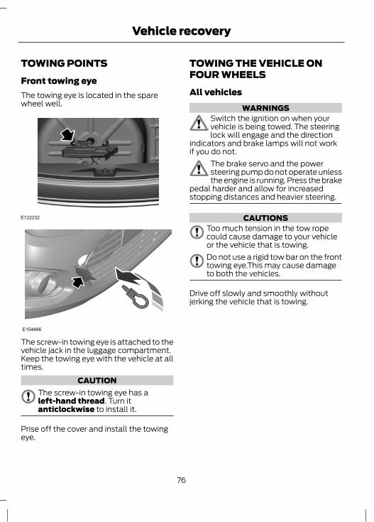
TOWING POINTSFront towing eyeThe towing eye is located in the sparewheel well.
E122232
E154486
The screw-in towing eye is attached to thevehicle jack in the luggage compartment.Keep the towing eye with the vehicle at alltimes.
CAUTIONThe screw-in towing eye has aleft-hand thread. Turn itanticlockwise to install it.
Prise off the cover and install the towingeye.
TOWING THE VEHICLE ONFOUR WHEELSAll vehicles
WARNINGSSwitch the ignition on when yourvehicle is being towed. The steeringlock will engage and the direction
indicators and brake lamps will not workif you do not.
The brake servo and the powersteering pump do not operate unlessthe engine is running. Press the brake
pedal harder and allow for increasedstopping distances and heavier steering.
CAUTIONSToo much tension in the tow ropecould cause damage to your vehicleor the vehicle that is towing.Do not use a rigid tow bar on the fronttowing eye.This may cause damageto both the vehicles.
Drive off slowly and smoothly withoutjerking the vehicle that is towing.
76
Vehicle recovery
GENERAL INFORMATIONHave your vehicle serviced regularly to helpmaintain its roadworthiness and resalevalue. There is a large network of FordAuthorised Repairers that are there to helpyou with their professional servicingexpertise. We believe that their speciallytrained technicians are best qualified toservice your vehicle properly and expertly.They are supported by a wide range ofhighly specialised tools developedspecifically for servicing your vehicle.In addition to regular servicing, werecommend that you carry out thefollowing additional checks.
WARNINGSSwitch the ignition off beforetouching or attempting adjustmentof any kind.Do not touch the electronic ignitionsystem parts after you have switchedthe ignition on or when the engine is
running. The system operates at highvoltage.
Keep your hands and clothing clearof the engine cooling fan. Undercertain conditions, the fan may
continue to run for several minutes afteryou have switched the engine off.
CAUTIONWhen carrying out maintenancechecks, make sure that filler caps arefitted securely.
Daily checks• Exterior lamps.• Interior lamps.• Warning lamps and indicators.
Check when refuelling• Engine oil level. See Engine Oil Check
(page 81).• Brake fluid level. See Brake and
Clutch Fluid Check (page 83).• Washer fluid level. See Washer Fluid
Check (page 84).• Tyre pressures (when cold). See
Technical Specifications (page 97).• Tyre condition. See Tyre Care (page
97).
Monthly checks• Engine coolant level (engine cold). See
Engine Coolant Check (page 83).• Pipes, hoses and reservoirs for leaks.• Power steering fluid level. See Power
Steering Fluid Check (page 84).• Air conditioning operation.• Parking brake operation.• Horn operation.• Tightness of wheel nuts. See
Technical Specifications (page 97).
OPENING AND CLOSING THEBONNETOpening the bonnet1. Pull the lever.
77
Maintenance

E120200
1
2. Raise the bonnet slightly and pull thecatch towards you.
3. Lift the bonnet from the lock.
E120201
2
3
4. Open the bonnet.5. Support the bonnet with the bonnet
stay rod.
E120202
4
5
Closing the bonnetNote: Make sure that the bonnet is closedproperly.Lower the bonnet and allow it to drop fromunder its own weight for the last 20 – 30centimetres.
78
Maintenance
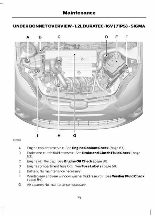
UNDER BONNET OVERVIEW - 1.2L DURATEC-16V (71PS) - SIGMA
E121060
FECBA
GI H
D
Engine coolant reservoir: See Engine Coolant Check (page 83).ABrake and clutch fluid reservoir: See Brake and Clutch Fluid Check (page83).
B
Engine oil filler cap: See Engine Oil Check (page 81).CEngine compartment fuse box. See Fuse Labels (page 69).DBattery: No maintenance necessary.EWindscreen and rear window washer fluid reservoir: See Washer Fluid Check(page 84).
F
Air cleaner: No maintenance necessary.G
79
Maintenance
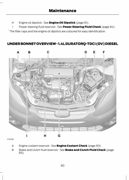
Engine oil dipstick: See Engine Oil Dipstick (page 81).HPower steering fluid reservoir: See Power Steering Fluid Check (page 84).I
* The filler caps and the engine oil dipstick are coloured for easy identification.
UNDER BONNET OVERVIEW - 1.4L DURATORQ-TDCI (DV) DIESEL
E121061
FECBA
GI H
D
Engine coolant reservoir: See Engine Coolant Check (page 83).ABrake and clutch fluid reservoir: See Brake and Clutch Fluid Check (page83).
B
80
Maintenance
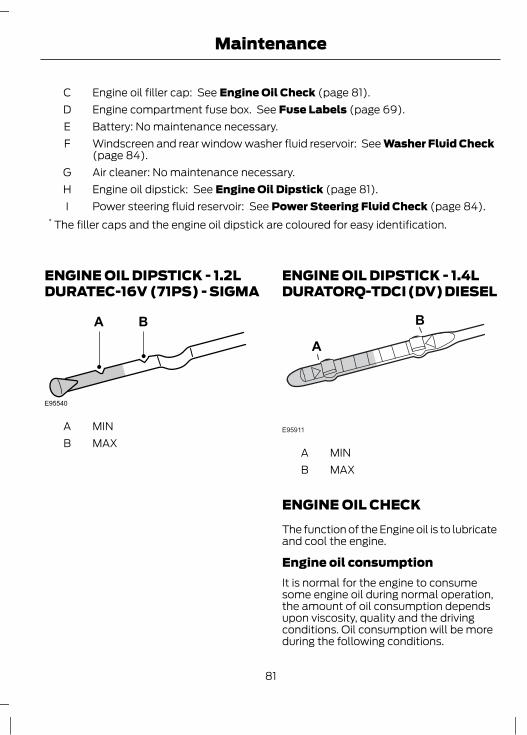
Engine oil filler cap: See Engine Oil Check (page 81).CEngine compartment fuse box. See Fuse Labels (page 69).DBattery: No maintenance necessary.EWindscreen and rear window washer fluid reservoir: See Washer Fluid Check(page 84).
F
Air cleaner: No maintenance necessary.GEngine oil dipstick: See Engine Oil Dipstick (page 81).HPower steering fluid reservoir: See Power Steering Fluid Check (page 84).I
* The filler caps and the engine oil dipstick are coloured for easy identification.
ENGINE OIL DIPSTICK - 1.2LDURATEC-16V (71PS) - SIGMA
E95540
BA
MINAMAXB
ENGINE OIL DIPSTICK - 1.4LDURATORQ-TDCI (DV) DIESEL
E95911
A
B
MINAMAXB
ENGINE OIL CHECKThe function of the Engine oil is to lubricateand cool the engine.
Engine oil consumptionIt is normal for the engine to consumesome engine oil during normal operation,the amount of oil consumption dependsupon viscosity, quality and the drivingconditions. Oil consumption will be moreduring the following conditions.
81
Maintenance
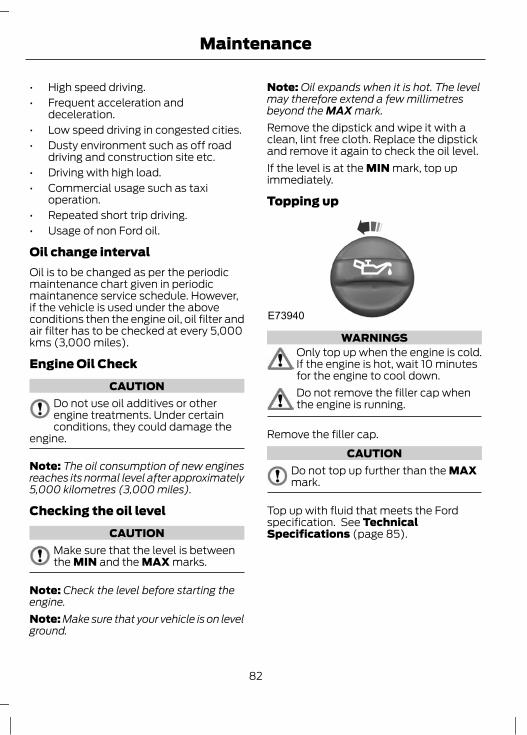
• High speed driving.• Frequent acceleration and
deceleration.• Low speed driving in congested cities.• Dusty environment such as off road
driving and construction site etc.• Driving with high load.• Commercial usage such as taxi
operation.• Repeated short trip driving.• Usage of non Ford oil.
Oil change intervalOil is to be changed as per the periodicmaintenance chart given in periodicmaintanence service schedule. However,if the vehicle is used under the aboveconditions then the engine oil, oil filter andair filter has to be checked at every 5,000kms (3,000 miles).
Engine Oil CheckCAUTION
Do not use oil additives or otherengine treatments. Under certainconditions, they could damage the
engine.
Note: The oil consumption of new enginesreaches its normal level after approximately5,000 kilometres (3,000 miles).
Checking the oil levelCAUTION
Make sure that the level is betweenthe MIN and the MAX marks.
Note: Check the level before starting theengine.Note: Make sure that your vehicle is on levelground.
Note: Oil expands when it is hot. The levelmay therefore extend a few millimetresbeyond the MAX mark.Remove the dipstick and wipe it with aclean, lint free cloth. Replace the dipstickand remove it again to check the oil level.If the level is at the MIN mark, top upimmediately.
Topping up
E73940
WARNINGSOnly top up when the engine is cold.If the engine is hot, wait 10 minutesfor the engine to cool down.Do not remove the filler cap whenthe engine is running.
Remove the filler cap.CAUTION
Do not top up further than the MAXmark.
Top up with fluid that meets the Fordspecification. See TechnicalSpecifications (page 85).
82
Maintenance
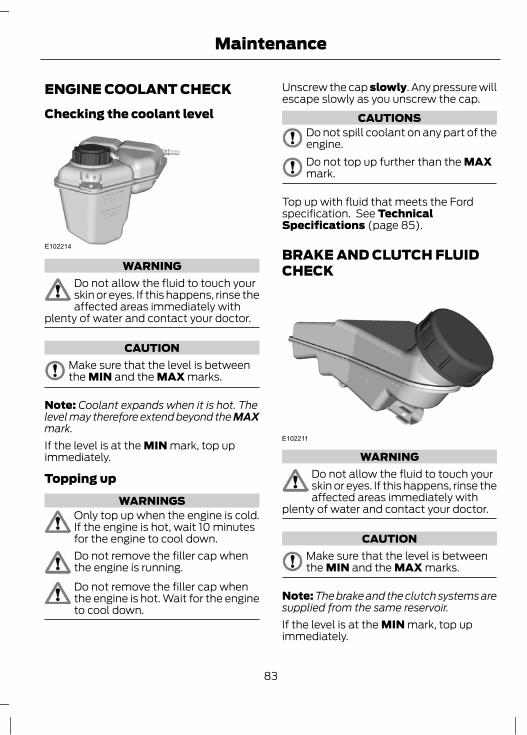
ENGINE COOLANT CHECKChecking the coolant level
E102214
WARNINGDo not allow the fluid to touch yourskin or eyes. If this happens, rinse theaffected areas immediately with
plenty of water and contact your doctor.
CAUTIONMake sure that the level is betweenthe MIN and the MAX marks.
Note: Coolant expands when it is hot. Thelevel may therefore extend beyond the MAXmark.If the level is at the MIN mark, top upimmediately.
Topping upWARNINGS
Only top up when the engine is cold.If the engine is hot, wait 10 minutesfor the engine to cool down.Do not remove the filler cap whenthe engine is running.Do not remove the filler cap whenthe engine is hot. Wait for the engineto cool down.
Unscrew the cap slowly. Any pressure willescape slowly as you unscrew the cap.
CAUTIONSDo not spill coolant on any part of theengine.Do not top up further than the MAXmark.
Top up with fluid that meets the Fordspecification. See TechnicalSpecifications (page 85).
BRAKE AND CLUTCH FLUIDCHECK
E102211
WARNINGDo not allow the fluid to touch yourskin or eyes. If this happens, rinse theaffected areas immediately with
plenty of water and contact your doctor.
CAUTIONMake sure that the level is betweenthe MIN and the MAX marks.
Note: The brake and the clutch systems aresupplied from the same reservoir.If the level is at the MIN mark, top upimmediately.
83
Maintenance
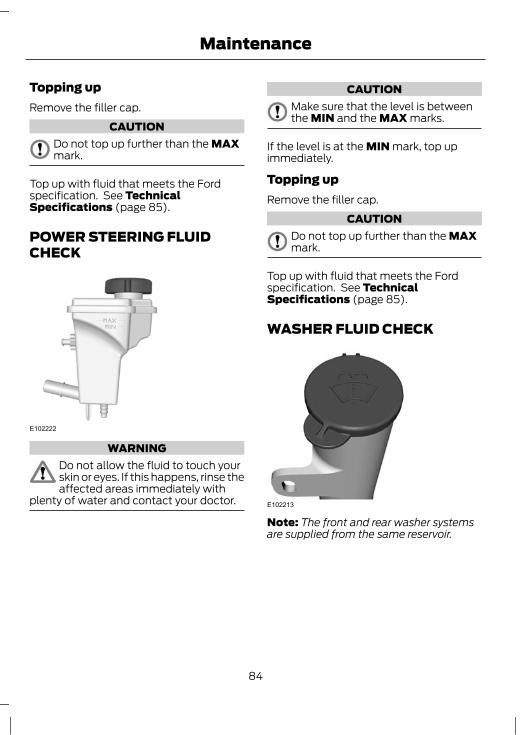
Topping upRemove the filler cap.
CAUTIONDo not top up further than the MAXmark.
Top up with fluid that meets the Fordspecification. See TechnicalSpecifications (page 85).
POWER STEERING FLUIDCHECK
E102222
WARNINGDo not allow the fluid to touch yourskin or eyes. If this happens, rinse theaffected areas immediately with
plenty of water and contact your doctor.
CAUTIONMake sure that the level is betweenthe MIN and the MAX marks.
If the level is at the MIN mark, top upimmediately.
Topping upRemove the filler cap.
CAUTIONDo not top up further than the MAXmark.
Top up with fluid that meets the Fordspecification. See TechnicalSpecifications (page 85).
WASHER FLUID CHECK
E102213
Note: The front and rear washer systemsare supplied from the same reservoir.
84
Maintenance
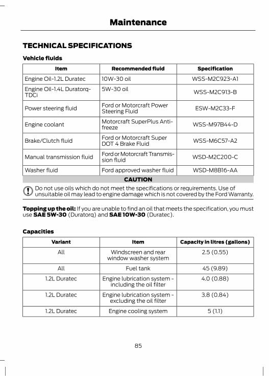
TECHNICAL SPECIFICATIONSVehicle fluids
SpecificationRecommended fluidItem
WSS-M2C923-A110W-30 oilEngine Oil-1.2L Duratec
WSS-M2C913-B5W-30 oilEngine Oil-1.4L Duratorq-TDCi
ESW-M2C33-FFord or Motorcraft PowerSteering FluidPower steering fluid
WSS-M97B44-DMotorcraft SuperPlus Anti-freezeEngine coolant
WSS-M6C57-A2Ford or Motorcraft SuperDOT 4 Brake FluidBrake/Clutch fluid
WSD-M2C200-CFord or Motorcraft Transmis-sion fluidManual transmission fluid
WSD-M8B16-AAFord approved washer fluidWasher fluidCAUTION
Do not use oils which do not meet the specifications or requirements. Use ofunsuitable oil may lead to engine damage which is not covered by the Ford Warranty.
Topping up the oil: If you are unable to find an oil that meets the specification, you mustuse SAE 5W-30 (Duratorq) and SAE 10W-30 (Duratec).
Capacities
Capacity in litres (gallons)ItemVariant
2.5 (0.55)Windscreen and rearwindow washer system
All
45 (9.89)Fuel tankAll
4.0 (0.88)Engine lubrication system -including the oil filter
1.2L Duratec
3.8 (0.84)Engine lubrication system -excluding the oil filter
1.2L Duratec
5 (1.1)Engine cooling system1.2L Duratec
85
Maintenance
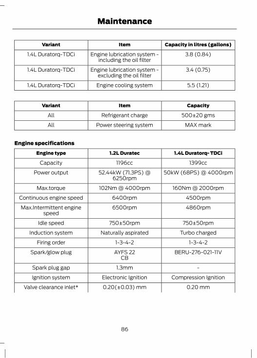
Capacity in litres (gallons)ItemVariant
3.8 (0.84)Engine lubrication system -including the oil filter
1.4L Duratorq-TDCi
3.4 (0.75)Engine lubrication system -excluding the oil filter
1.4L Duratorq-TDCi
5.5 (1.21)Engine cooling system1.4L Duratorq-TDCi
CapacityItemVariant
500±20 gmsRefrigerant chargeAll
MAX markPower steering systemAll
Engine specifications
1.4L Duratorq- TDCi1.2L DuratecEngine type
1399cc1196ccCapacity
50kW (68PS) @ 4000rpm52.44kW (71.3PS) @6250rpm
Power output
160Nm @ 2000rpm102Nm @ 4000rpmMax.torque
4500rpm6400rpmContinuous engine speed
4860rpm6500rpmMax.Intermittent enginespeed
750±50rpm750±50rpmIdle speed
Turbo chargedNaturally aspiratedInduction system
1-3-4-21-3-4-2Firing order
BERU-276-021-11VAYFS 22Spark/glow plugCB
-1.3mmSpark plug gap
Compression IgnitionElectronic IgnitionIgnition system
0.20 mm0.20(±0.03) mmValve clearance inlet*
86
Maintenance
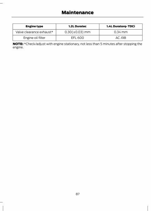
1.4L Duratorq- TDCi1.2L DuratecEngine type
0.34 mm0.30(±0.03) mmValve clearance exhaust*
AC J9BEFL 600Engine oil filter
NOTE: *Check/adjust with engine stationary, not less than 5 minutes after stopping theengine.
87
Maintenance
CLEANING THE EXTERIOR
WARNINGIf you use a car wash with a waxingcycle, make sure that you remove thewax from the windscreen.
CAUTIONSPrior to using a car wash facility checkthe suitability of it for your vehicle.Some car wash installations usewater at high pressure. This coulddamage certain parts of your vehicle.Remove the aerial before using anautomatic car wash.Switch the heater blower off toprevent contamination of the fresh airfilter.
We recommend that you wash your vehiclewith a sponge and lukewarm watercontaining a car shampoo.
Cleaning the headlampsCAUTIONS
Do not scrape the headlamp lensesor use abrasives, alcoholic solvents orchemical solvents to clean them.Do not wipe the headlamps whenthey are dry.
Cleaning the rear windowCAUTION
Do not scrape the inside of the rearwindow or use abrasives or chemicalsolvents to clean it.
Use a clean, lint free cloth or a dampchamois leather to clean the inside of therear window.
Cleaning the chrome trimCAUTION
Do not use abrasives or chemicalsolvents. Use soapy water.
Cleaning the alloy wheelsNote: Do not apply a cleaning chemical towarm or hot wheel rims and covers.Note: Industrial-strength (heavy-duty)cleaners, or cleaning chemicals, incombination with brush agitation to removebrake dust and dirt, could wear away theclear coat finish over a period time.Note: Do not use hydrofluoric acid-basedor high caustic-based wheel cleaners, steelwool, fuels or strong household detergent.Note: If you intend parking your vehicle foran extended period after cleaning thewheels with a wheel cleaner, drive yourvehicle for a few minutes before doing so.This will reduce the risk of increasedcorrosion of the brake discs, brake pads andlinings.Note: Some automatic car washes maycause damage to the finish on your wheelrims and covers.Alloy wheels and wheel covers are coatedwith a clear coat paint finish. To maintaintheir condition we recommend that you:• Clean them weekly with the
recommended wheel and tyre cleaner.• Use a sponge to remove heavy
deposits of dirt and brake dustaccumulation.
• Rinse them thoroughly with apressurised stream of water when youhave completed the cleaning process.
We recommend that you use Ford servicewheel cleaner. Make sure that you readand follow the manufacturer’s instructions.
88
Vehicle Care
Using other non-recommended cleaningproducts can result in severe andpermanent cosmetic damage.
Body paintwork preservationCAUTIONS
Do not polish your vehicle in strongsunshine.Do not allow polish to touch plasticsurfaces. It could be difficult toremove.Do not apply polish to the windscreenor rear window. This could cause thewipers to become noisy and they may
not clear the window properly.
We recommend that you wax thepaintwork once or twice a year.
CLEANING THE INTERIORSeat belts
WARNINGSDo not use abrasives, or chemicalsolvents to clean them.Do not allow moisture to penetratethe seat belt retractor mechanism.
Clean the seat belts with interior cleaneror water applied with a soft sponge. Letthe seat belts dry naturally, away fromartificial heat.
Instrument cluster screens, LCDscreens, radio screens
WARNINGDo not use abrasives, alcoholicsolvents or chemical solvents toclean them.
Rear windowsCAUTIONS
Do not use any abrasive materials toclean the interior of the rear windows.Do not install stickers or labels to theinterior of the rear windows.
REPAIRING MINOR PAINTDAMAGE
CAUTIONRemove apparently harmless lookingsubstances from the paintworkimmediately (e.g. bird droppings, tree
resins, insect remains, tar spots, road saltand industrial fall out).
You should repair paintwork damagecaused by stones from the road or minorscratches as soon as possible. A choice ofproducts is available from your FordDealer. Read and follow themanufacturer’s instructions.
89
Vehicle Care
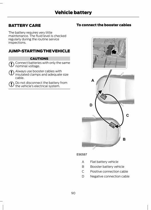
BATTERY CAREThe battery requires very littlemaintenance. The fluid level is checkedregularly during the routine serviceinspections.
JUMP-STARTING THE VEHICLE
CAUTIONSConnect batteries with only the samenominal voltage.Always use booster cables withinsulated clamps and adequate sizecable.Do not disconnect the battery fromthe vehicle’s electrical system.
To connect the booster cables
E90587
A
B
D
C
Flat battery vehicleABooster battery vehicleBPositive connection cableCNegative connection cableD
90
Vehicle battery

Vehicles with a petrol engine
CAUTIONSDo not connect to the negative (–)terminal of the flat battery.Make sure that the jump leads areclear of any moving parts.
1. Position the vehicles so that they donot touch one another.
2. Switch off the engine and any electricalequipment.
3. Connect the positive (+) terminal ofvehicle A with the positive (+) terminalof vehicle B (cable C).
4. Connect the negative (-) terminal ofvehicle B to the engine block or enginemount of vehicle A (cable D), as farfrom the battery as possible.
Vehicles with a diesel engine
CAUTIONSDo not connect to the negative (–)terminal of the flat battery.Make sure that the jump leads areclear of any moving parts.
1. Position the vehicles so that they donot touch one another.
2. Switch off the engine and any electricalequipment.
3. Connect the positive (+) terminal ofvehicle A with the positive (+) terminalof vehicle B (cable C).
4. Connect the negative (-) terminal ofvehicle B to the turbocharger of vehicleA (cable D).
To start the engine1. Run the engine of vehicle B at
moderately high speed.2. Start the engine of vehicle A.
3. Run both vehicles for a minimum ofthree minutes before disconnecting theleads.
CAUTIONDo not switch on the headlamps whendisconnecting the cables. The peakvoltage could blow the bulbs.
Disconnect the cables in the reverse order.
91
Vehicle battery
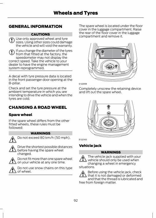
GENERAL INFORMATION
CAUTIONSUse only approved wheel and tyresizes. Using other sizes could damagethe vehicle and will void the warranty.If you change the diameter of the tyresfrom that fitted at the factory, thespeedometer may not display the
correct speed. Take the vehicle to yourdealer to have the engine managementsystem reprogrammed.
A decal with tyre pressure data is locatedin the front passenger door opening at theB-pillar.Check and set the tyre pressure at theambient temperature in which you areintending to drive the vehicle and when thetyres are cold.
CHANGING A ROAD WHEELSpare wheelIf the spare wheel differs from the otherfitted wheels, these rules must befollowed:
WARNINGSDo not exceed 80 km/h (50 mph).
Drive the shortest possible distancesbefore having the spare wheelchanged.Do not fit more than one spare wheelon your vehicle at any one time.Do not use snow chains on this typeof wheel.
The spare wheel is located under the floorcover in the luggage compartment. Raisethe rear of the floor cover in the luggagecompartment and remove it.
E122058
Completely unscrew the retaining deviceand lift out the spare wheel.
E122163
Vehicle jackWARNINGS
The vehicle jack supplied with yourvehicle should only be used whenchanging a wheel in emergency
situations.Before using the vehicle jack, checkthat it is not damaged or deformedand that the thread is lubricated and
free from foreign matter.
92
Wheels and Tyres
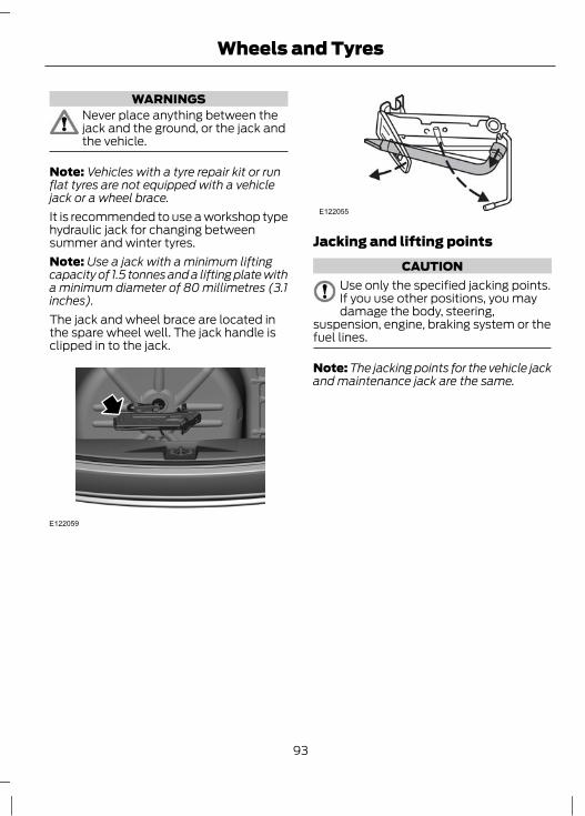
WARNINGSNever place anything between thejack and the ground, or the jack andthe vehicle.
Note: Vehicles with a tyre repair kit or runflat tyres are not equipped with a vehiclejack or a wheel brace.It is recommended to use a workshop typehydraulic jack for changing betweensummer and winter tyres.Note: Use a jack with a minimum liftingcapacity of 1.5 tonnes and a lifting plate witha minimum diameter of 80 millimetres (3.1inches).The jack and wheel brace are located inthe spare wheel well. The jack handle isclipped in to the jack.
E122059
E122055
Jacking and lifting pointsCAUTION
Use only the specified jacking points.If you use other positions, you maydamage the body, steering,
suspension, engine, braking system or thefuel lines.
Note: The jacking points for the vehicle jackand maintenance jack are the same.
93
Wheels and Tyres

E120276
A
Maintenance jackA
E122056
E93184
A
Indentations in the sills A show thelocation of the jacking points.
94
Wheels and Tyres
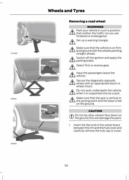
E113400
E92932
E93020
Removing a road wheelWARNINGS
Park your vehicle in such a positionthat neither the traffic nor you arehindered or endangered.Set up a warning triangle.
Make sure that the vehicle is on firm,level ground with the wheels pointingstraight ahead.Switch off the ignition and apply theparking brake.Select first or reverse gear.
Have the passengers leave thevehicle.Secure the diagonally oppositewheel with an appropriate block orwheel chock.Do not work underneath the vehiclewhen it is supported only by a jack.Make sure that the jack is vertical tothe jacking point and the base is flaton the ground.
CAUTIONDo not lay alloy wheels face down onthe ground, this will damage the paint.
1. Insert the flat end of the wheel bracebetween the rim and the hub cover andcarefully remove the hub cap or cover.
95
Wheels and Tyres

E90922
2. Fully extend the wheel brace ifapplicable.
3. Slacken the wheel nuts.4. Jack up the vehicle until the tyre is clear
of the ground.5. Remove the wheel nuts and the wheel.
Installing a road wheelWARNINGS
Use only approved wheel and tyresizes. Using other sizes coulddamage the vehicle and will make
the National Type Approval invalid. SeeTechnical Specifications (page 97).
Do not fit run flat tyres on vehiclesthat were not originally fitted withthem. Please contact your dealer for
more details regarding compatibility.Make sure that the arrows ondirectional tyres point in the directionof rotation when the vehicle is
moving forwards. If you have to fit a sparewheel with the arrows pointing in theopposite direction, have the tyre refittedin the correct direction by a properlytrained technician.
CAUTIONDo not install alloy wheels usingwheel nuts designed for use with steelwheels.
Note: Make sure the wheel and hub contactsurfaces are free from foreign matter.Note: Make sure that the cones on thewheel nuts are against the wheel.1. Install the wheel.
E90922
2. Install the wheel nuts finger tight.
1 2
3
4
E90589
3. Partially tighten the wheel nuts in thesequence shown.
96
Wheels and Tyres

4. Lower the vehicle and remove the jack.5. Fully tighten the wheel nuts in the
sequence shown. See TechnicalSpecifications (page 97).
6. Install the hub cap or cover using theball of your hand.
WARNINGHave the wheel nuts checked fortightness and the tyre pressurechecked as soon as possible.
TYRE CARETyre rotation including spare wheel
E120217
Tyre rotation without spare wheel
E70415
To make sure the front and rear tyres ofyour vehicle wear evenly and last longer,we recommend that you swap the tyresfrom front to rear and vice versa at regularintervals of between 5,000 and 10,000 km(3,000 and 6,000 miles).
CAUTIONDo not scrub the sidewalls of the tyreswhen you are parking.
If you have to mount a kerb, do so slowlyand approach it with the wheels atright-angles to the kerb.Examine the tyres regularly for cuts, foreignobjects and uneven wear of the tread.Uneven wear could mean that the wheelalignment is outside specification.Check the tyre pressures (including thespare) when cold, every two weeks.
TECHNICAL SPECIFICATIONSWheel nut torque
Specification Nm (lb-ft)Variant
95 (70)All (except alloy wheel)
133 (98)Alloy wheel
97
Wheels and Tyres
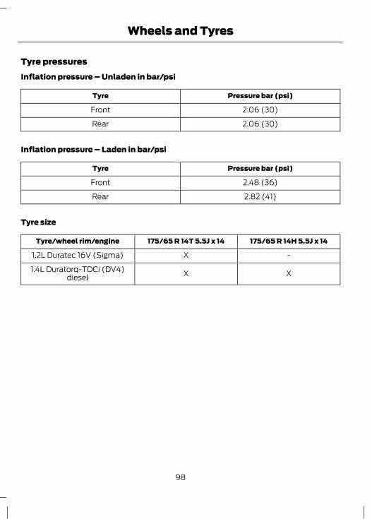
Tyre pressuresInflation pressure – Unladen in bar/psi
Pressure bar (psi)Tyre
2.06 (30)Front
2.06 (30)Rear
Inflation pressure – Laden in bar/psi
Pressure bar (psi)Tyre
2.48 (36)Front
2.82 (41)Rear
Tyre size
175/65 R 14H 5.5J x 14175/65 R 14T 5.5J x 14Tyre/wheel rim/engine
-X1.2L Duratec 16V (Sigma)
XX1.4L Duratorq-TDCi (DV4)diesel
98
Wheels and Tyres

VEHICLE IDENTIFICATION NUMBER
E121140
The vehicle identification number isstamped into the floor panel on theright-hand side, below the front driver seat.
99
Vehicle identification
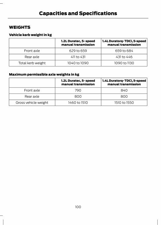
WEIGHTSVehicle kerb weight in kg
1.4L Duratorq- TDCi, 5-speedmanual transmission
1.2L Duratec, 5- speedmanual transmission
659 to 684629 to 659Front axle
431 to 446411 to 431Rear axle
1090 to 11301040 to 1090Total kerb weight
Maximum permissible axle weights in kg
1.4L Duratorq- TDCi, 5-speedmanual transmission
1.2L Duratec, 5- speedmanual transmission
840790Front axle
800800Rear axle
1510 to 15501460 to 1510Gross vehicle weight
100
Capacities and Specifications
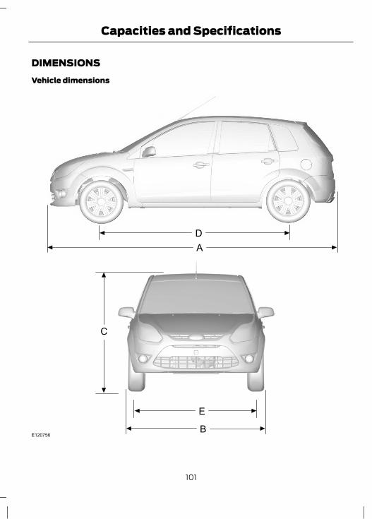
DIMENSIONSVehicle dimensions
DA
E
C
BE120756
101
Capacities and Specifications

Dimension in mm(inches)
Dimension DescriptionItem
3795 (149.4)Maximum lengthA
1912 (75.3)Overall width including exterior mirrorsB
1427 (56.2)Overall height at EC kerb weightC
2489 (98.0)WheelbaseD
1465 (57.7)Front trackE
1435 (56.5)Rear trackE
102
Capacities and Specifications
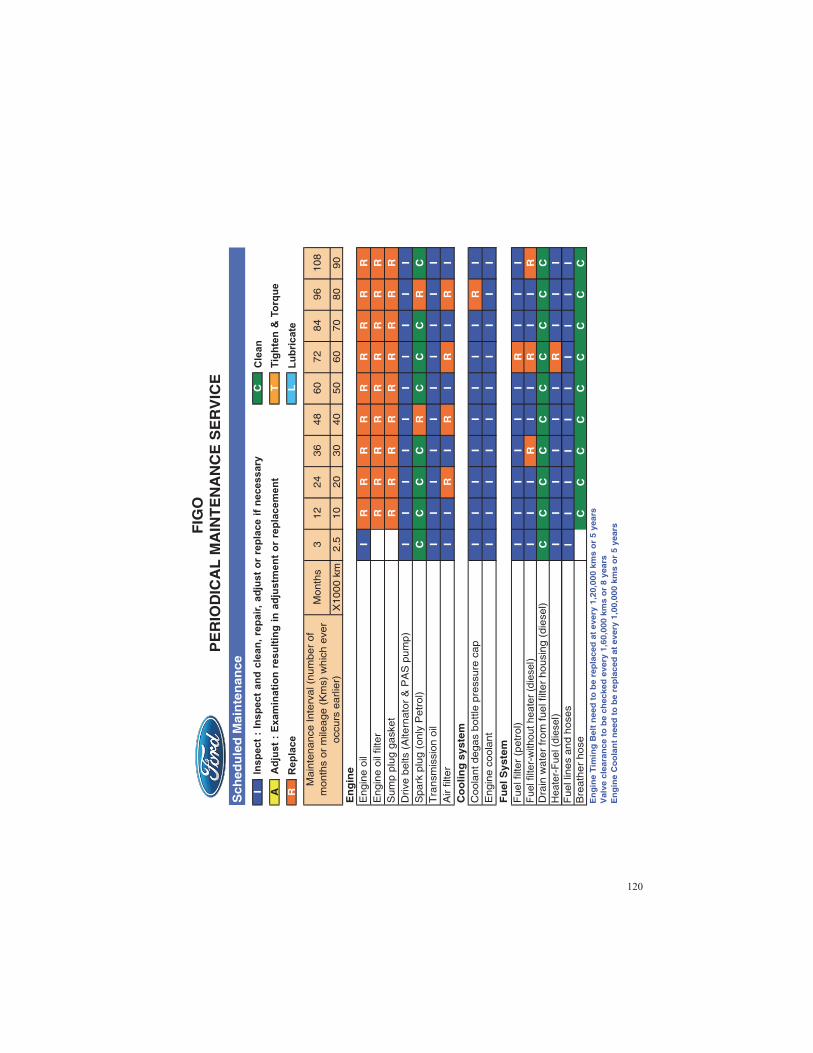


AA/C
See: Climate Control...........................................47About This Manual...........................................5ABS
See: Brakes.............................................................62ABS driving hints
See: Hints on Driving With Anti-LockBrakes..................................................................62
AccessoriesSee: Replacement Parts
Recommendation..............................................5Adjusting the Steering Wheel....................26Adjusting the windscreen washer
jets....................................................................29Air Conditioning
See: Climate Control...........................................47Air Vents.............................................................47Arming the engine immobiliser.................25ASL
See: Automatic speed limiter (ASL)............64At a Glance..........................................................7
Adjusting the steering wheel..............................9Cooling the interior quickly.................................9Defrosting and demisting the
windscreen...........................................................9Engine idle speed after starting........................8Information display................................................9Instrument panel overview - RHD....................7Locking and unlocking the doors with the
remote control....................................................9Warning lamps and indicators...........................8
Audio Control...................................................26Mode..........................................................................27Seek...........................................................................26Volume.....................................................................26
Automatic speed limiter (ASL)................64Principle of Operation........................................64
Auxiliary Power Points..................................55Audio jack................................................................55
BBattery care.....................................................90Bonnet Lock
See: Opening and Closing the Bonnet..........77
Booster cablesSee: Jump-Starting the Vehicle.....................90
Booster Seats....................................................11Booster cushion (Group 3).................................11Booster seat (Group 2)........................................11
Brake and Clutch Fluid Check...................83Topping up..............................................................84
Brakes.................................................................62Principle of Operation........................................62
Bulb changingSee: Changing a Bulb..........................................35
Bulb Specification Chart.............................38
CCapacities and Specifications................100Car Wash
See: Cleaning the Exterior................................88Catalytic Converter........................................59
Driving with a catalytic converter...................59Changing a Bulb.............................................35
Central high mounted stop lamp...................37Courtesy lamp.......................................................38Front direction indicators..................................36Headlamp main and dipped beam...............35Luggage compartment lamp..........................38Number plate lamp.............................................38Rear lamps..............................................................36Side lamps..............................................................36Side repeaters.......................................................36
Changing a Fuse.............................................69Changing a Road Wheel..............................92
Installing a road wheel......................................96Jacking and lifting points..................................93Removing a road wheel.....................................95Spare wheel...........................................................92Vehicle jack.............................................................92
Changing the remote controlbattery..............................................................21
Changing the Wiper Blades.......................30Checking the Wiper Blades........................30Child Safety........................................................11Child Safety Locks..........................................14Child Seat Positioning...................................13Child Seats.........................................................12
Child restraints for different massgroups...................................................................12
103
Index

Cleaning the Exterior....................................88Body paintwork preservation..........................89Cleaning the alloy wheels................................88Cleaning the chrome trim.................................88Cleaning the headlamps...................................88Cleaning the rear window.................................88
Cleaning the Interior.....................................89Instrument cluster screens, LCD screens,
radio screens....................................................89Rear windows........................................................89Seat belts................................................................89
Climate Control...............................................47Principle of Operation.........................................47
Coded keys........................................................25Convenience features...................................55Coolant Check
See: Engine Coolant Check..............................83
DDimensions......................................................101Direction Indicators.......................................34Disarming the engine immobiliser...........25Driving Hints.....................................................66Driving Through Water.................................66
Driving through water ........................................66
EElectric exterior mirrors.................................41Engine Coolant Check..................................83
Checking the coolant level...............................83Topping up..............................................................83
Engine immobiliser........................................25Principle of Operation.........................................25
Engine Oil Check.............................................81Checking the oil level..........................................82Engine Oil Check...................................................82Engine oil consumption......................................81Oil change interval...............................................82Topping up..............................................................82
Engine Oil Dipstick - 1.2L Duratec-16V(71PS) - Sigma..............................................81
Engine Oil Dipstick - 1.4L Duratorq-TDCi(DV) Diesel.....................................................81
Exterior Mirrors................................................40Folding mirrors......................................................40Manual Exterior Mirrors.......................................41
FFastening the seat belts...............................18First Aid Kit........................................................67Fog Lamps - Front
See: Front Fog Lamps.........................................33Front Fog Lamps............................................33Fuel and Refuelling.......................................59Fuel Consumption.........................................60
Erratic driving habits...........................................60Length of journey/engine
temperature......................................................60Traffic and road conditions..............................60Vehicle condition.................................................60Vehicle load conditions.....................................60
Fuel Cut-Off Switch......................................68Vehicles with a Duratec Petrol engine.........68
Fuel filler flap...................................................59Fuel Quality - Diesel.....................................60Fuel Quality - Petrol.....................................60Fuse Box Locations........................................74
Engine compartment fuse box........................74Passenger compartment fuse box................74
Fuse Labels......................................................69Fuses..................................................................69Fuse Specification Chart.............................70
Engine junction box.............................................70Passenger junction box.......................................71
GGauges...............................................................42
Fuel gauge...............................................................43Speedometer.........................................................43Tachometer............................................................43Theater dimming..................................................43
GearboxSee: Transmission.................................................61
General Driving Points.................................66Vehicles with a diesel engine..........................66
General Information on RadioFrequencies...................................................20
Glove Box..........................................................55
HHandbrake
See: Parking Brake...............................................63
104
Index
Hazard Warning Flashers............................33Headlamp Levelling.......................................32
Recommended headlamp levelling switchpositions.............................................................33
Head Restraints..............................................53Adjusting the head restraint.............................53Removing the head restraint...........................53
Heated Windows...........................................50Heating
See: Climate Control...........................................47Hints on Driving With Anti-Lock
Brakes..............................................................62
IIgnition Switch.................................................57
Ignition switch positions....................................57Immobiliser
See: Engine immobiliser....................................25Information Displays....................................46
General Information...........................................46Inspecting safety system
components.................................................68Seat belts................................................................68
Instrument Cluster.........................................42Interior Lamps.................................................34
Courtesy lamp.......................................................34Luggage compartment lamp...........................35
Interior Mirror....................................................41Introduction........................................................5
JJump starting
See: Jump-Starting the Vehicle.....................90Jump-Starting the Vehicle.........................90
To connect the booster cables.......................90To start the engine................................................91
KKeys and Remote Controls.........................20
LLighting Control...............................................32
Headlamp flasher.................................................32Main/dipped beam..............................................32Welcome lighting..................................................32
Lighting...............................................................32Load Carrying..................................................65
General Information............................................65Locking and Unlocking.................................22
Central locking.......................................................22Locking and unlocking confirmation.............22Locking and unlocking the doors with the
key and inner handle......................................22Locking and unlocking the doors with the
remote control..................................................23Manual locking......................................................22
Locks...................................................................22Luggage Covers..............................................65
MMaintenance.....................................................77
General Information.............................................77Technical Specifications...................................85
Manual Climate Control..............................48Air distribution control.......................................48Blower......................................................................48Cooling the interior quickly...............................49Cooling with outside air.....................................49Defrosting and demisting the
windscreen........................................................48Heating the interior quickly..............................50Reducing interior air humidity.........................50Switching the air conditioning on and
off..........................................................................49Switching the recirculated air on and
off..........................................................................49Temperature control...........................................48Ventilation..............................................................49
Manual Seats....................................................51Adjusting the angle of the seatback.............52Adjusting the height of the driver’s
seat.......................................................................52Moving the seats backwards and
forwards...............................................................51Manual Transmission....................................61
Reverse gear............................................................61
105
Index
Message CentreSee: Information Displays.................................46
MirrorsSee: Windows and Mirrors...............................40
OOccupant protection.....................................15
Principle of Operation..........................................15Oil Check
See: Engine Oil Check..........................................81Opening and Closing the Bonnet..............77
Closing the bonnet...............................................78Opening the bonnet.............................................77
PParking Brake...................................................63
Applying the parking brake...............................63Parking on a hill.....................................................63Releasing the parking brake.............................63
Power Door LocksSee: Locking and Unlocking.............................22
Power Steering Fluid Check.......................84Topping up..............................................................84
Power Windows.............................................40Manual windows..................................................40
Programming the remote control............20Re-programming the unlocking
function...............................................................20
RRear Seats.........................................................53
.....................................................................................54Creating a level load floor.................................53Folding the seatbacks down............................53
Rear Window Wiper and Washers...........29Washer.....................................................................29
Refuelling..........................................................60Remote control battery
See: Changing the remote controlbattery..................................................................21
Remote control programmingSee: Programming the remote control........20
Repairing Minor Paint Damage.................89
Replacement PartsRecommendation..........................................5Look for the Ford logo on the following
parts .......................................................................6Now you can be sure that your Ford parts
are Ford parts......................................................5Roadside Emergencies.................................67Running-In........................................................66
Brakes and clutch................................................66Engine......................................................................66Tyres..........................................................................66
SSafety Precautions........................................59Seat belts
See: Fastening the seat belts...........................18Seats....................................................................51Sitting in the Correct Position.....................51Starter Switch
See: Ignition Switch.............................................57Starting a Diesel Engine..............................58
Cold or hot engine...............................................58Flooded Engine.....................................................58
Starting and Stopping the Engine............57General Information............................................57
Starting a Petrol Engine...............................57Cold or hot engine................................................57Engine idle speed after starting......................58Flooded engine.....................................................58
Status after a collision.................................68Steering Wheel...............................................26Sun Visors.........................................................55Switching Off the Engine............................58
Vehicles with a turbocharger...........................58Symbols Glossary.............................................5
Symbols in this handbook...................................5Symbols on your vehicle......................................5
TTechnical Specifications
See: Capacities and Specifications............100Towing Points..................................................76
Front towing eye...................................................76Towing the Vehicle on Four Wheels........76
All vehicles..............................................................76Transmission.....................................................61
106
Index
Tyre Care............................................................97Tyre Pressures
See: Technical Specifications..........................97Tyres
See: Wheels and Tyres.......................................92
UUnder Bonnet Overview - 1.2L
Duratec-16V (71PS) - Sigma...................79Under Bonnet Overview - 1.4L
Duratorq-TDCi (DV) Diesel.....................80USB Port............................................................56Using seat belts during pregnancy...........19
VVehicle battery................................................90Vehicle Care.....................................................88Vehicle Identification Number..................99Vehicle identification....................................99Vehicle recovery..............................................76Ventilation
See: Climate Control...........................................47Vents
See: Air Vents.........................................................47VIN
See: Vehicle Identification Number..............99
WWarning Lamps and Indicators.................43
ABS warning lamp...............................................43Airbag warning lamp...........................................43Brake system warning lamp............................44Direction indicator................................................45Door open warning lamp..................................44Engine check warning lamp.............................45Engine coolant temperature warning
lamp.....................................................................45Front fog lamp indicator....................................45Glow plug indicator.............................................45Ignition warning lamp........................................44Illumination ON indicator..................................45Low fuel level warning lamp............................44Main beam indicator...........................................45MIL.............................................................................44Oil pressure warning lamp...............................44Water in fuel warning lamp (vehicles with
diesel engine)...................................................45Warning Triangle.............................................67Washer Fluid Check......................................84Washers
See: Wipers and Washers.................................28Washing
See: Cleaning the Exterior................................88Weights............................................................100Wheels and Tyres...........................................92
General Information............................................92Technical Specifications....................................97
Windows and Mirrors...................................40Windscreen Washers....................................28Windscreen Wipers.......................................28
Intermittent wiping..............................................28Wipers and Washers.....................................28
107
Index

108

Related Documents