The Influence of the End Effector Gyroscopic Torques on a Base of the Manipulator Jaros law Go´ sli´ nski, Stanis law Gardecki and Wojciech Giernacki Pozna´ n University of Technology, Institute of Control and Information Engineering, ul. Piotrowo 3A, 60-965 Pozna´ n, Poland [email protected] [email protected] [email protected] http://www.cie.put.poznan.pl/ Abstract. In this paper, the model of the robotic arm with payload is presented. The payload is configured as a rotating mass, which imitate the tool on a robot’s wrist. While manipulating with working tool the gyroscopic effect can occur. This leads to extra moments in each joint of the manipulator. In order to evaluate the scale of the process and the consequences in the robot’s trajectory, mathematical model of the robot including rotating mass was derived. The system was simulated for different parameters. It was proven that the gyroscopic effect cannot be neglected, especially when the robot’s movement are rapid and conducted simultaneously in more then one joint at once. For the purpose of the work, authors decided to use manipulator with five degrees of freedom, equipped with rotational joints only. Keywords: gyroscopic effect, manipulator, mathematical modeling 1 Introduction Robotic arms are used in many applications especially in industry for assembling, welding, riveting etc. Some of other applications includes robotic arms in space (space manipulators). Space manipulators and special manipulators on assembly lines may have long arms or many joints. These features increase maneuverabil- ity as well as agility, though may lead to problems in control. The problem is particularly visible while working with rotating payloads. Torques and forces in each joint depend on arm’s angular velocity, joint variables and external forces. One of external torques stem from tool mounted on a wrist, which is a spinning mass. In space manipulators, the problem is even more sophisticated - the gyro- scopic effect form spinning rotors of the drive motors affect on the chassis of the spacecraft/base station [1]. On the other hand, the same principle of spinning mass can be used as a drives for actuators as a Control-Moment Gyroscopes (CMGs) [2]. CMGs can reduce the base reactions or even eliminate them, while using the same amount of power as a robotic system driven by conventional joint

Welcome message from author
This document is posted to help you gain knowledge. Please leave a comment to let me know what you think about it! Share it to your friends and learn new things together.
Transcript
The Influence of the End Effector GyroscopicTorques on a Base of the Manipulator
Jaros law Goslinski, Stanis law Gardecki and Wojciech Giernacki
Poznan University of Technology,Institute of Control and Information Engineering,
ul. Piotrowo 3A, 60-965 Poznan, [email protected]
http://www.cie.put.poznan.pl/
Abstract. In this paper, the model of the robotic arm with payload ispresented. The payload is configured as a rotating mass, which imitatethe tool on a robot’s wrist. While manipulating with working tool thegyroscopic effect can occur. This leads to extra moments in each jointof the manipulator. In order to evaluate the scale of the process andthe consequences in the robot’s trajectory, mathematical model of therobot including rotating mass was derived. The system was simulated fordifferent parameters. It was proven that the gyroscopic effect cannot beneglected, especially when the robot’s movement are rapid and conductedsimultaneously in more then one joint at once. For the purpose of thework, authors decided to use manipulator with five degrees of freedom,equipped with rotational joints only.
Keywords: gyroscopic effect, manipulator, mathematical modeling
1 Introduction
Robotic arms are used in many applications especially in industry for assembling,welding, riveting etc. Some of other applications includes robotic arms in space(space manipulators). Space manipulators and special manipulators on assemblylines may have long arms or many joints. These features increase maneuverabil-ity as well as agility, though may lead to problems in control. The problem isparticularly visible while working with rotating payloads. Torques and forces ineach joint depend on arm’s angular velocity, joint variables and external forces.One of external torques stem from tool mounted on a wrist, which is a spinningmass. In space manipulators, the problem is even more sophisticated - the gyro-scopic effect form spinning rotors of the drive motors affect on the chassis of thespacecraft/base station [1]. On the other hand, the same principle of spinningmass can be used as a drives for actuators as a Control-Moment Gyroscopes(CMGs) [2]. CMGs can reduce the base reactions or even eliminate them, whileusing the same amount of power as a robotic system driven by conventional joint
2 The Gyroscopic Effect in a Robot Manipulator
motors. Regardless of type of effects (desirable or side) the influence of spinningmass in robot mechanical system cannot be neglected without its prior evalu-ation. In this paper authors derive the mathematical model of a manipulatorwith five degrees of freedom with payload attached on the last joint. In order toassess the level of influence of gyroscopic effect on the manipulator, simulationsfor payloads with different weights and angular velocities were shown. In thearticle, the first paragraph describes the robotic arm. In the next section themanipulator model is derived and described. In the third and fourth paragraphthe model is enhanced with the gyroscopic effect. The fifth paragraph shows thesimulations results. Finally in the last paragraph conclusions are presented.
2 The manipulator model
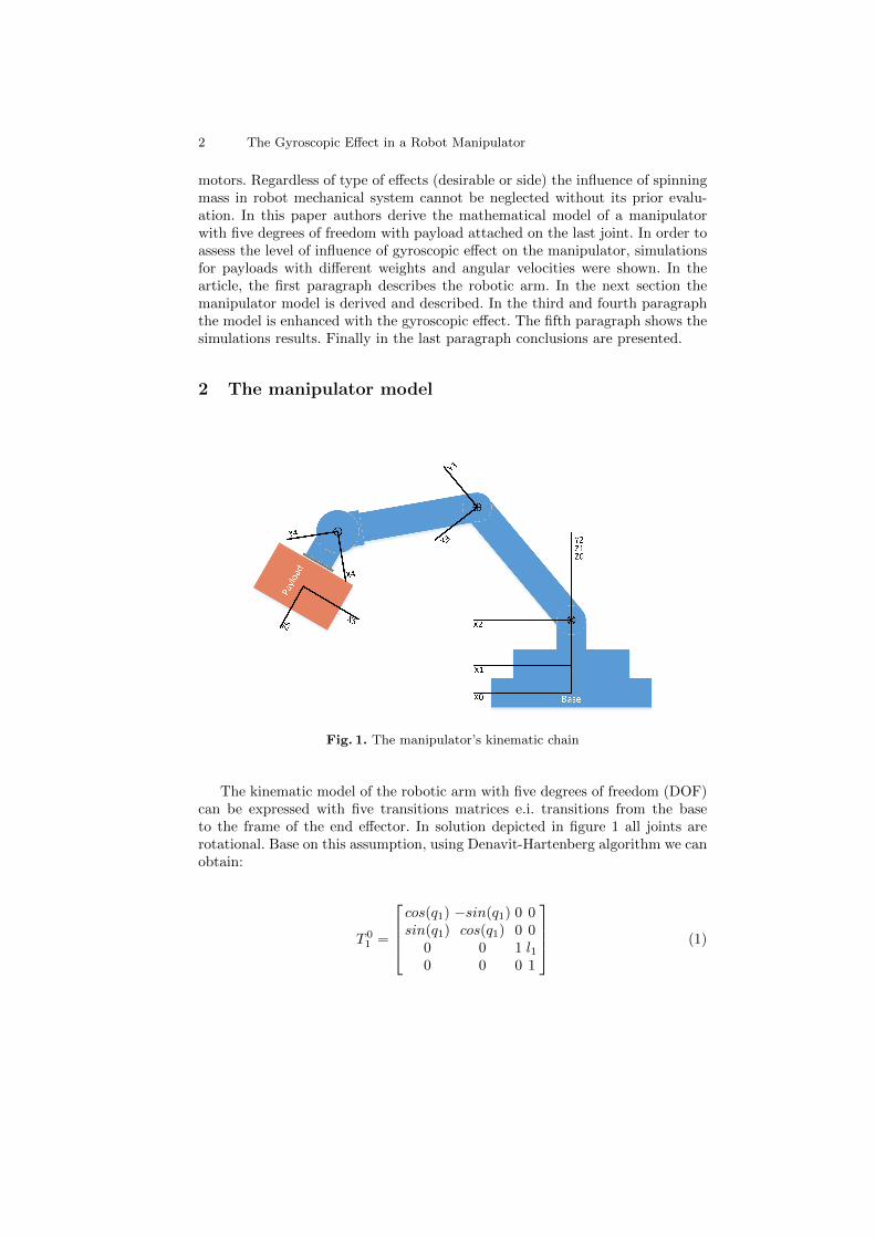
Fig. 1. The manipulator’s kinematic chain
The kinematic model of the robotic arm with five degrees of freedom (DOF)can be expressed with five transitions matrices e.i. transitions from the baseto the frame of the end effector. In solution depicted in figure 1 all joints arerotational. Base on this assumption, using Denavit-Hartenberg algorithm we canobtain:
T 01 =
cos(q1) −sin(q1) 0 0sin(q1) cos(q1) 0 0
0 0 1 l10 0 0 1
(1)

The Gyroscopic Effect in a Robot Manipulator 3
T 12 =
cos(q2) 0 −sin(q2) 0sin(q2) 0 cos(q2) 0
0 −1 0 l20 0 0 1
(2)
T 23 =
cos(q3) −sin(q3) 0 l3cos(q3)sin(q3) cos(q3) 0 l3sin(q3)
0 0 1 00 0 0 1
(3)
T 34 =
cos(q4) −sin(q4) 0 l4cos(q4)sin(q4) cos(q4) 0 l4sin(q4)
0 0 1 00 0 0 1
(4)
T 45 =
cos(q5) 0 sin(q5) l5cos(q5)sin(q5) 0 −cos(q5) l5sin(q5)
0 1 0 00 0 0 1
(5)
Each transition matrix T i−1i describes coordinate i expressed in coordinate i −
1. In order to derive the mathematical model of the manipulator, all of themanipulator’s matrices must be defined. Matrices describe the robot dynamicsand they are defined, base on previously shown transition matrices and inertiatensors. The manipulator equation can be written in one of many forms, herethe standard form [3] is presented:
D(q)q + C(q, q) +G(q) = τ (6)
D(q) denotes inertia matrix, C(q, q) denotes centrifugal and Coriolis forces, vec-tor G(q) indicates gravitational forces. In purpose of simulations, the standardmanipulator equation is extended to its real form with friction matrix B:
D(q)q + C(q, q) +G(q) +Bq = τ (7)
The simplest form of friction matrix is a diagonal matrix with viscous frictionelements for each joint:
B =
b1 0 0 0 00 b2 0 0 00 0 b3 0 00 0 0 b4 00 0 0 0 b5
(8)
Matrix D is symmetric and it is composed with dij (where i, j ∈ 1, 2, ..., 5):
4 The Gyroscopic Effect in a Robot Manipulator
D(q) =
d11 d12 d13 d14 d15d21 d22 d23 d24 d25d31 d32 d33 d34 d35d41 d42 d43 d44 d45d51 d52 d53 d54 d55
, (9)
where the elements on main diagonal are as follows:
d11 = (Ix3 +Ix4 +Ix5 +Iy3 +Iy4 +Iz5)/2+Iz1 +Iy2− (Ix4cos(2q3 +2q4))/2
+(Iy4cos(2q3 +2q4))/2+(l23m3)/8+(l23m4)/2+(l23m5)/2+(l24m4)/8+(l24m5)/2
+ (l25m5)/8− (Ix3cos(2q3))/2 + (Iy3cos(2q3))/2− (Ix5cos(2q3 + 2q4 + 2q5))/2
+ (Iz5cos(2q3 + 2q4 + 2q5))/2 + (l23m3cos(2q3))/8 + (l23(m4 +m5)cos(2q3))/2
+(l25m5cos(2q3+2q4+2q5))/8+(l24m4cos(2q3+2q4))/8+(l24m5cos(2q3+2q4))/2
+(l3l5m5cos(2q3 +q4 +q5))/2+(l3l5m5cos(q4 +q5))/2+ l3l4(m5 +m4/2)cos(q4)
+ (l4l5m5cos(q5))/2 + (l4l5m5cos(2q3 + 2q4 + q5))/2 + (l3l4m4cos(2q3 + q4))/2
+ l3l4m5cos(2q3 + q4) (10)
d22 = (Ix3 + Ix4 + Ix5 + Iy3 + Iy4 + Iz5)/2 + Iy2 − (Ix4cos(2q3 + 2q4))/2
+(Iy4cos(2q3 +2q4))/2+(l23m3)/8+(l23m4)/2+(l23m5)/2+(l24m4)/8+(l24m5)/2
+(l25m5)/8−(Ix3cos(2q3))/2+((Iy3cos(2q3))−((Ix5+Iz5)cos(2q3+2q4+2q5)))/2
+ l23(m3/8 +m4/2 +m5/2)cos(2q3) + (l25m5cos(2q3 + 2q4 + 2q5))/8
+(l24m4cos(2q3 +2q4))/8+(l24m5cos(2q3 +2q4))/2+(l3l5m5cos(2q3 +q4 +q5))/2
+(l3l5m5cos(q4 +q5))/2+(l3l4m4cos(q4))/2+ l3l4m5cos(q4)+(l4l5m5cos(q5))/2
+(l4l5m5cos(2q3+2q4+q5))/2+(l3l4m4cos(2q3+q4))/2+ l3l4m5cos(2q3+q4)(11)
d33 = Iy5 + Iz3 + Iz4 + (l23m3)/4 + l23m4 + l23m5 + (l24m4)/4 + l24m5 + (l25m5)/4
+ l3l5m5cos(q4 + q5) + l3l4m4cos(q4) + 2l3l4m5cos(q4) + l4l5m5cos(q5) (12)
d44 = Iy5 + Iz4 + (l24m4)/4 + l24m5 + (l25m5)/4 + l4l5m5cos(q5) (13)
d55 = (m5l25)/4 + Iy5 (14)
Elements that are non-diagonal can be expressed as follows:
d12 = d21 = (Ix3 + Ix4 + Ix5 + Iy3 + Iy4 + Iz5) + Iy2− (Ix4cos(2q3 + 2q4))/2
+(Iy4cos(2q3 +2q4))/2+(l23m3)/8+(l23m4)/2+(l23m5)/2+(l24m4)/8+(l24m5)/2
+ (l25m5)/8 + ((Iy3 − Ix3)cos(2q3))/2 + ((Iz5 − Ix5)cos(2q3 + 2q4 + 2q5))/2
+ (l23(m3/8 +m4/2 +m5/2)cos(2q3))/8 + (l25m5cos(2q3 + 2q4 + 2q5))/8
+(l24m4cos(2q3 +2q4))/8+(l24m5cos(2q3 +2q4))/2+(l3l5m5cos(2q3 +q4 +q5))/2
+(l3l5m5cos(q4 +q5))/2+(l3l4m4cos(q4))/2+ l3l4m5cos(q4)+(l4l5m5cos(q5))/2
+(l4l5m5cos(2q3+2q4+q5))/2+(l3l4m4cos(2q3+q4))/2+ l3l4m5cos(2q3+q4)(15)
The Gyroscopic Effect in a Robot Manipulator 5
d13 = d14 = d15 = d23 = d24 = d25 = 0 (16)
d34 = d43 = Iy5 + Iz4 + (l24m4)/4 + l24m5 + (l25m5)/4 + (l3l5m5cos(q4 + q5))/2
+ (l3l4m4cos(q4))/2 + l3l4m5cos(q4) + l4l5m5cos(q5) (17)
d35 = d53 = Iy5 +(l25m5)/4+(l3l5m5cos(q4 +q5))/2+(l4l5m5cos(q5))/2 (18)
d45 = d54 = (m5l25)/4 + (l4m5cos(q5)l5)/2 + Iy5 (19)
The C matrix can be presented as a full matrix or as a vector. Vector ofcentrifugal and Coriolis forces is derived as product of multiplication: C(q, q)qand can be written in a form:
C =
c1c2c3c4c5
, (20)
where:
c1 = c2 = −((dq1+dq2)(4Iy3dq3sin(2q3)−4(Ix5(dq4+dq3)sin(2q3+2q4+2q5)
+ Ix3dq3sin(2q3))− 4Ix5dq5sin(2q3 + 2q4 + 2q5) + 4Iz5dq3sin(2q3 + 2q4 + 2q5)
+4Iz5dq4sin(2q3+2q4+2q5)+4Iz5dq5sin(2q3+2q4+2q5)−4Ix4dq3sin(2q3+2q4)
−4(Ix4dq4sin(2q3+2q4)+Iy4(dq3+dq4)sin(2q3+2q4))+dq3l23(m3+4m4)sin(2q3)
+4dq3l23m5sin(2q3)+(dq3+dq4)l25m5sin(2q3+2q4+2q5)+dq3l
24m4sin(2q3+2q4)
+dq5l25m5sin(2q3 +2q4 +2q5)+4dq4l
24m5sin(2q3 +2q4)+dq4l
24m4sin(2q3 +2q4)
+ 4dq3l24m5sin(2q3 + 2q4) + 4dq3l3l4m4sin(2q3 + q4) + 8dq3l3l4m5sin(2q3 + q4)
+ dq4l3l4(2m4 + 4m5)sin(2q3 + q4) + (4dq3 + 2dq4)l3l5m5sin(2q3 + q4 + q5)
+2dq5l3l5m5sin(2q3 +q4 +q5)+2dq4l3l5m5sin(q4 +q5)+2dq5l3l5m5sin(q4 +q5)
+dq4l3l4(2m4+4m5)sin(q4)+2dq5l4l5m5sin(q5)+4dq3l4l5m5sin(2q3+2q4+q5)
+ 4dq4l4l5m5sin(2q3 + 2q4 + q5) + 2dq5l4l5m5sin(2q3 + 2q4 + q5)))/4
(21)
c3 = (dq1(dq1 + dq2)(4Iy4sin(2q3 + 2q4)− 4Ix4sin(2q3 + 2q4)− 4Ix3sin(2q3)
+ 4Iy3sin(2q3) + 4(Iz5− Ix5)sin(2q3 + 2q4 + 2q5) + l24(4m5 +m4)sin(2q3 + 2q4)
+l23(m3+4m4+4m5)sin(2q3)+l25m5sin(2q3+2q4+2q5)+4l3l5m5sin(2q3+q4+q5)
+ 4l4l5m5sin(2q3 + 2q4 + q5) + 4l3l4m4sin(2q3 + q4) + 8l3l4m5sin(2q3 + q4)))/8
+ ((dq4 + dq5 − dq4dq3)l3l5m5sin(q4 + q5))/2 + dq3l3l4(m4/2 +m5)sin(q4)
+dq4l3l4(m4/2+m5)sin(q4))+(dq5l4l5m5sin(q5))−dq3((dq4l3l5m5sin(q4+q5))/2
+ (dq5l3l5m5sin(q4 + q5))/2 + (dq4l3l4m4sin(q4))/2 + dq4l3l4m5sin(q4)
+(dq5l4l5m5sin(q5))/2)+(dq2(dq1+dq2)(4Iy4sin(2q3+2q4)−4Ix4sin(2q3+2q4)
−4Ix3sin(2q3)+4Iy3sin(2q3)−4Ix5sin(2q3+2q4+2q5)+4Iz5sin(2q3+2q4+2q5)
+ l24m4sin(2q3 + 2q4) + 4l24m5sin(2q3 + 2q4) + l23m3sin(2q3) + 4l23m4sin(2q3)
6 The Gyroscopic Effect in a Robot Manipulator
+ 4l23m5sin(2q3) + l25m5sin(2q3 + 2q4 + 2q5) + 4(l3 + l4)l5m5sin(2q3 + q4 + q5)
+ 4l3l4m4sin(2q3 + q4) + 8l3l4m5sin(2q3 + q4)))/8− (dq5l5m5(l3sin(q4 + q5)
+ l4sin(q5))(dq3 + dq4 + dq5))/2 (22)
c4 = dq3((dq3l3l5m5sin(q4 + q5))/2 + (dq3l3l4m4sin(q4))/2 + dq3l3l4m5sin(q4)
−(dq5l4l5m5sin(q5))/2)+(dq1(dq1+dq2)(4Iy4sin(2q3+2q4)−4Ix4sin(2q3+2q4)
− 4Ix5sin(2q3 + 2q4 + 2q5) + 4Iz5sin(2q3 + 2q4 + 2q5) + l24m4sin(2q3 + 2q4)
+ 4l24m5sin(2q3 + 2q4) + l25m5sin(2q3 + 2q4 + 2q5) + 2l3l5m5sin(2q3 + q4 + q5)
+2l3l5m5sin(q4+q5)+2l3l4m4sin(q4)+4l3l4m5sin(q4)+4l4l5m5sin(2q3+2q4+q5)
+ 2l3l4m4sin(2q3 + q4) + 4l3l4m5sin(2q3 + q4)))/8
+(dq2(dq1+dq2)(4Iy4sin(2q3+2q4)−4Ix4sin(2q3+2q4)−4Ix5sin(2q3+2q4+2q5)
+4Iz5sin(2q3+2q4+2q5)+l24(m4+4m5)sin(2q3+2q4)+l25m5sin(2q3+2q4+2q5)
+2l3l5m5sin(2q3+q4+q5)+2l3l5m5sin(q4+q5)+2l3l4m4sin(q4)+4l3l4m5sin(q4)
+ 4l4l5m5sin(2q3 + 2q4 + q5) + 2l3l4m4sin(2q3 + q4) + 4l3l4m5sin(2q3 + q4)))/8
− (dq4dq5l4l5m5sin(q5))/2− (dq5l4l5m5sin(q5)(dq3 + dq4 + dq5))/2
(23)
c5 = (dq1(dq1+dq2)(4(Iz5−Ix5)sin(2q3+2q4+2q5)+l25m5sin(2q3+2q4+2q5)
+2l3l5m5(sin(2q3+q4+q5)+sin(q4+q5))+2l4l5m5(sin(q5)+sin(2q3+2q4+q5))))/8
+ (dq2(dq1 + dq2)(4(Iz5 − Ix5)sin(2q3 + 2q4 + 2q5) + l25m5sin(2q3 + 2q4 + 2q5)
+ 2(l3 + l4)l5m5sin(2q3 + q4 + q5) + 2l3l5m5sin(q4 + q5) + 2l4l5m5sin(q5)))/8
+(dq3l5m5((dq3+dq4)l4sin(q5)+dq3l3sin(q4+q5))+dq4l4l5m5sin(q5)(dq3+dq4))/2(24)
Vector C has an explicit form, which is not valid in case of matrix C(q, q). Thatmatrix can be written in many different and correct configurations. The last partof the model, given by equation 7 is a vector of gravitational forces G(q). Thenext elements of the G can be written as:
g1 = g2 = 0 (25)
g3 = −m5g(l4cos(q3 + q4) + l3cos(q3) + (l5cos(q3 + q4 + q5))/2)
−m4g((l4cos(q3 + q4))/2 + l3cos(q3))− (l3m3gcos(q3))/2 (26)
g4 = −m5g(l4cos(q3 + q4) + (l5cos(q3 + q4 + q5))/2)− (l4m4gcos(q3 + q4))/2(27)
g5 = −(l5m5gcos(q3 + q4 + q5))/2 (28)
In model’s matrices and vectors, li denotes i-th arm’s length, qi, dqi andddqi denote respectively: i-th joint angular position, i-th angular speed and i-thangular acceleration. Inertia tensors were calculated with assumption, that thecenter of the mass for each arm is located in the middle of arm (li/2).
The Gyroscopic Effect in a Robot Manipulator 7
3 Gyroscopic torques
The gyroscopic effect can be described as a cross product of precession’s angularvelocity (ω) and an angular momentum of the spinning mass (Lm). When thegyroscope is mounted on the manipulator’s end effector, then the precession isan angular velocity of the Tool Center Point (TCP) expressed in base coordinatesystem. The gyroscope general formula is given by:
τg = ω × Lm (29)In the case of the manipulator, an angular velocity is a combination of all
joint’s angular velocities in a kinematic chain [3]:ω = ω0
n = ω01 +R0
1ω12 +R0
2ω23 +R0
3ω34 + ...+R0
n−1ωn−1n (30)
Each ωn−1n vector has only one element corresponding to the Z-axis, in accor-
dance with D-H notation e.i.:
ωn−1n =
00dqn
(31)
The last rotational joint has got spinning mass attached to it, and the lastcoordinate system in which the calculations of the gyroscope torque must bemade is the static (q5 = 0, dq5 = 0) fifth frame. The total angular velocity,expressed in the base coordinate system is given as follows:
ω04 =
−sin(q1 + q2)(dq2 + dq3 + dq4)cos(q1 + q2)(dq2 + dq3 + dq4)
dq1
(32)
whereas the angular momentum of the spinning mass in the fifth joint is equalto:
Lm =
00
Imdq5
(33)
Finally, the cross product of angular velocity and the angular momentum iscalculated:
τg =
Imdq5cos(q1 + q2)(dq2 + dq3 + dq4)Imdq5sin(q1 + q2)(dq2 + dq3 + dq4)
0
(34)
Torque τg is expressed in the last static coordinate system e.i. in coordinate ofthe end effector.
4 The influence of gyroscopic effect on robot joints
In previous section, the torque of gyroscopic effect was derived. Here the influenceof this torque on mechanical structure of the manipulator is evaluated. Firstly,the overall formula for the torques projection form the joint n+ 1 to the joint nmust be derived. Base on [3], it can be written that (without forces):
τn = Rn+1n τn+1 (35)
where the rotation matrix Rn+1n is a part of transition matrix Tn+1
n :
8 The Gyroscopic Effect in a Robot Manipulator
Tn+1n =
[Rn+1
n 3×3 Pn+1n 3×1
0 0 0 1
]. (36)
The equation 35 can be extended to all joints, making it possible to project thetorque form the fourth to the base coordinate system (note that: τ5 = τg):
τ0 = R10R
21R
32R
43R
54τ5 (37)
Since the rotation matrix is orthogonal, its inverse is equal to transposition:
τ0 = R01TR1
2TR2
3TR3
4TR4
5Tτ5 (38)
Having the formula given above, the total torque generated in end effector,projected on the base coordinate system, can be stated as:
τ0 =
τ0xτ0yτ0z
(39)
where:
τ0x = Imdq5sin(q1 + q2)sin(q1)(dq2 + dq3 + dq4) + Imdq5cos(q1 + q2)·(cos(q4)(cos(q1)cos(q2)cos(q3)− cos(q1)sin(q2)sin(q3))− sin(q4)(cos(q1)·
cos(q2)sin(q3) + cos(q1)cos(q3)sin(q2)))(dq2 + dq3 + dq4) (40)
τ0y = Imdq5sin(q1 + q2)cos(q1)(dq2 + dq3 + dq4) + Imdq5cos(q1 + q2)·(cos(q4)(sin(q1)sin(q2)sin(q3)− cos(q2)cos(q3)sin(q1)) + sin(q4)(cos(q2)·
sin(q1)sin(q3) + cos(q3)sin(q1)sin(q2)))(dq2 + dq3 + dq4) (41)
τ0z = −Imdq5sin(q2 + q3 + q4)cos(q1 + q2)(dq2 + dq3 + dq4) (42)
5 Simulations results
Since the influence of gyroscopic torques on robot’s joints is already determinedby equations, the overall torque can be evaluated. Here, the experiment is nar-rowed only to the zero coordinate system (robot’s base). It is due to the simpli-fication of number of cases, where for one joint this task is straight. As it waswritten in equations (39)-(42) the base coordinate system is under the influenceof gyroscopic torques in all three axis. Since the rotational joint of robot’s baseis only in Z-axis, in the rest two axis, acting torques force only the mechanicalstructure of the robot. Nevertheless, authors decided to show all figures, stress-ing the range of torque values. The experiment was conducted on virtual robotmanipulator with following parameters:l1 = 0.2m, l2 = 0.4m, l3 = l4 = 1.0m, l5 = 0.4m, m1 = 20,m2 = 40,m3 =40,m4 = 25,m5 = 10; Ix1 = 0.4, Ix2 = 0.4, Ix3 = 0.3, Ix4 = 0.15, Ix5 =0.20, Iy1 = 0.22, Iy2 = 0.4, Iy3 = 0.4, Iy4 = 0.18, Iy5 = 0.2, Iz1 = 0.3, Iz2 =0.5, Iz3 = 0.5, Iz4 = 0.2, Iz5 = 0.2; b1 = 0.9, b2 = 0.8, b3 = 0.7, b4 = 0.8, b5 =0.7
The Gyroscopic Effect in a Robot Manipulator 9
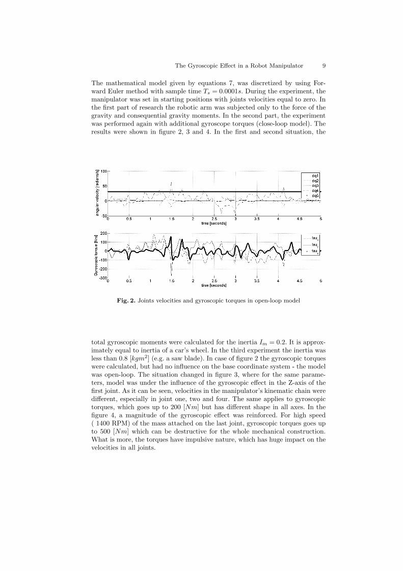
The mathematical model given by equations 7, was discretized by using For-ward Euler method with sample time Ts = 0.0001s. During the experiment, themanipulator was set in starting positions with joints velocities equal to zero. Inthe first part of research the robotic arm was subjected only to the force of thegravity and consequential gravity moments. In the second part, the experimentwas performed again with additional gyroscope torques (close-loop model). Theresults were shown in figure 2, 3 and 4. In the first and second situation, the
Fig. 2. Joints velocities and gyroscopic torques in open-loop model
total gyroscopic moments were calculated for the inertia Im = 0.2. It is approx-imately equal to inertia of a car’s wheel. In the third experiment the inertia wasless than 0.8 [kgm2] (e.g. a saw blade). In case of figure 2 the gyroscopic torqueswere calculated, but had no influence on the base coordinate system - the modelwas open-loop. The situation changed in figure 3, where for the same parame-ters, model was under the influence of the gyroscopic effect in the Z-axis of thefirst joint. As it can be seen, velocities in the manipulator’s kinematic chain weredifferent, especially in joint one, two and four. The same applies to gyroscopictorques, which goes up to 200 [Nm] but has different shape in all axes. In thefigure 4, a magnitude of the gyroscopic effect was reinforced. For high speed( 1400 RPM) of the mass attached on the last joint, gyroscopic torques goes upto 500 [Nm] which can be destructive for the whole mechanical construction.What is more, the torques have impulsive nature, which has huge impact on thevelocities in all joints.

10 The Gyroscopic Effect in a Robot Manipulator
Fig. 3. Joints velocities and gyroscopic torques in close-loop model
Fig. 4. Joints velocities and gyroscopic torques in close-loop model - high speed in fifthjoint
6 Summary
In the article, the mathematical model of 5 DOF manipulator was derived. Themodel was enhanced with additional equations, describing the gyroscopic effect.The gyroscopic effect was presented as a set of analytical equations (with torqueson the output). In accordance with assumptions, torques were projected fromthe end effector to the base coordinate system. Thanks to that, the simulationsof the manipulator with additional spinning mass, attached to the end effectorwere conducted. Three main dependencies have been studied: the influence of
The Gyroscopic Effect in a Robot Manipulator 11
inertia and velocity of spinning mass on the gyroscopic torques, the influence ofmanipulator’s joints velocities on overall torques and the model dynamics withand without the gyroscopic effect. Torques in the base coordinate system can goup to hundreds of Nm, while increasing the inertia and velocity of spinning mass.The dynamics of the manipulator is different with the modeled gyroscopic effect.It is important to keep in mind that the spinning objects in the end effector canhave extreme impact on a control system of manipulators. The gyroscope effectcan be neglected, but only if velocities in joint as well as velocity of tool or objectin the end effector are small. In any other cases the gyroscopic effect should bemodeled and evaluated prior to application.
References
1. Murphy, S.H., Wen, J.T.:Analysis of Active Manipulator Elements in Space Manip-ulation. IEEE Transactions on Robotics and Automation, Vol. 9, No. 5, 544–552(1993)
2. Carpenter, M.D., Peck, M.A.:Reducing Base Reactions With Gyroscopic Actuationof Space-Robotic Systems. IEEE Transactions on Robotics and Automation, Vol.25, No. 6, 1262–1270 (2009)
3. Spong, M. W.,Vidyasagar M.: Robot Dynamics and Control, First Edition. Thepublisher: John Wiley and Sons, Canada (1989)
Related Documents


![Upper Limb Deweighting using Underactuated End-effector ......upper-arm, forearm and hand) by computing compensation torques joint-by-joint (i.e. shoulder, elbow, wrist) [11]— operating](https://static.cupdf.com/doc/110x72/60b7c6aebf623c01ff24c748/upper-limb-deweighting-using-underactuated-end-effector-upper-arm-forearm.jpg)


