PRINTED IN U.S.A IMI CORNELIUS INC; January 1997 THE HOTTEST MACHINES ON ICEt Installation/Maintenance Instructions “I” Series Flaked/Nugget Ice Machines Model Number Description IAF1000 & 650 Flaker/Nugget Modular Head Ice Maker Air Cooled IWF1000 & 650 Flaker/Nugget Modular Head Ice Maker Water Cooled IRF1000 & 650 Flaker/Nugget Modular Head Ice Maker Remote Cooled Part No. 630460003 1/10/97 Revised 4/11/97 THIS DOCUMENT CONTAINS IMPORTANT INFORMATION This Manual must be read and understood before installing or operating this equipment

Welcome message from author
This document is posted to help you gain knowledge. Please leave a comment to let me know what you think about it! Share it to your friends and learn new things together.
Transcript
PRINTED IN U.S.AIMI CORNELIUS INC; January 1997
THE HOTTEST MACHINES ON ICE�
Installation/MaintenanceInstructions
“I” Series Flaked/Nugget Ice Machines
Model Number Description
IAF1000 & 650 Flaker/Nugget Modular Head Ice Maker Air Cooled
IWF1000 & 650 Flaker/Nugget Modular Head Ice Maker Water Cooled
IRF1000 & 650 Flaker/Nugget Modular Head Ice Maker Remote Cooled
Part No. 6304600031/10/97Revised 4/11/97
THIS DOCUMENT CONTAINS IMPORTANT INFORMATIONThis Manual must be read and understood before installing or operating this equipment
i 6304600003
TABLE OF CONTENTS
Page
INTRODUCTION 1. . . . . . . . . . . . . . . . . . . . . . . . . . . . . . . . . . . . . . . . . . . . . . . . . . . . . . . . . . .
ICE FLAKER SPECIFICATION 2. . . . . . . . . . . . . . . . . . . . . . . . . . . . . . . . . . . . . . . . . . . . . .
ICE FLAKER SPECIFICATION 3. . . . . . . . . . . . . . . . . . . . . . . . . . . . . . . . . . . . . . . . . . . . . .
AVERAGE OPERATING CHARACTERISTICS IAF1000 4. . . . . . . . . . . . . . . . . . . . . . . . . . . . . . . . . . . . . . . . . . . . . . . . . . . . . . . . . . . . . .
AVERAGE OPERATING CHARACTERISTICS IWF1000 4. . . . . . . . . . . . . . . . . . . . . . . . . . . . . . . . . . . . . . . . . . . . . . . . . . . . . . . . . . . . . .
AVERAGE OPERATING CHARACTERISTICS IRF1000 5. . . . . . . . . . . . . . . . . . . . . . . . . . . . . . . . . . . . . . . . . . . . . . . . . . . . . . . . . . . . . .
INSTALLATION INSTRUCTIONS 6. . . . . . . . . . . . . . . . . . . . . . . . . . . . . . . . . . . . . . . . . . . .
WATER AND ICE CIRCUIT 9. . . . . . . . . . . . . . . . . . . . . . . . . . . . . . . . . . . . . . . . . . . . .
ELECTRICAL CIRCUIT 10. . . . . . . . . . . . . . . . . . . . . . . . . . . . . . . . . . . . . . . . . . . . . . . . .
CIRCUIT DESCRIPTION 10. . . . . . . . . . . . . . . . . . . . . . . . . . . . . . . . . . . . . . . . . .
COMPONENT DESCRIPTION 10. . . . . . . . . . . . . . . . . . . . . . . . . . . . . . . . . . . . . . . . . .
BIN THERMOSTAT 10. . . . . . . . . . . . . . . . . . . . . . . . . . . . . . . . . . . . . . . . . . . . . . .
GEARMOTOR START RELAY 10. . . . . . . . . . . . . . . . . . . . . . . . . . . . . . . . . . . . .
COMPRESSOR CONTACTOR 10. . . . . . . . . . . . . . . . . . . . . . . . . . . . . . . . . . . . .
GEARMOTOR DELAY THERMOSTAT 10. . . . . . . . . . . . . . . . . . . . . . . . . . . . . .
ON–OFF SWITCH / CIRCUIT BREAKER 10. . . . . . . . . . . . . . . . . . . . . . . . . . . .
FAN CYCLING SWITCH (R404A UNITS) 11. . . . . . . . . . . . . . . . . . . . . . . . . . . .
HIGH PRESSURE CONTROL 11. . . . . . . . . . . . . . . . . . . . . . . . . . . . . . . . . . . . . .
COMPRESSOR START RELAY 11. . . . . . . . . . . . . . . . . . . . . . . . . . . . . . . . . . . .
POTENTIAL RELAYS 11. . . . . . . . . . . . . . . . . . . . . . . . . . . . . . . . . . . . . . . . . . . . .
CAPACITORS – GENERAL 11. . . . . . . . . . . . . . . . . . . . . . . . . . . . . . . . . . . . . . . .
DUMP SWITCH 11. . . . . . . . . . . . . . . . . . . . . . . . . . . . . . . . . . . . . . . . . . . . . . . . . .
MAINTENANCE 15. . . . . . . . . . . . . . . . . . . . . . . . . . . . . . . . . . . . . . . . . . . . . . . . . . . . . . . . . . .
“I” SERIES FLAKER CLEANING AND SANITIZING PROCEDURE 16. . . . . . . . . . . . . . . . . . . . . . . . . . . . . . . . . . . . . . . . . . . .
WATER TREATMENT 17. . . . . . . . . . . . . . . . . . . . . . . . . . . . . . . . . . . . . . . . . . . . . . . . . .
WINTER STORAGE 17. . . . . . . . . . . . . . . . . . . . . . . . . . . . . . . . . . . . . . . . . . . . . . . . . . .
CLEANING THE CONDENSER (AIR COOLED) 17. . . . . . . . . . . . . . . . . . . . . . . . . . .
TROUBLESHOOTING 21. . . . . . . . . . . . . . . . . . . . . . . . . . . . . . . . . . . . . . . . . . . . . . . . . .
ii6304600003
FIGURE AND ILLUSTRATIONS
FIGURE 1. BIN THERMOSTAT INSTALLATION 6. . . . . . . . . . . . . . . . . . . . . . . . . . .
FIGURE 2. SERVICE CONNECTIONS 7. . . . . . . . . . . . . . . . . . . . . . . . . . . . . . . . . . .
FIGURE 3. INSTRUCTIONS FOR CONVERTING
FLAKED ICE TO NUGGET ICE. 8. . . . . . . . . . . . . . . . . . . . . . . . . . . . . . . . . . . . . . . . .
FIGURE 4. WATER LEVEL 9. . . . . . . . . . . . . . . . . . . . . . . . . . . . . . . . . . . . . . . . . . . . . .
FIGURE 5. REFRIGERATION AND WATER SYSTEMS MODELS IAF1000, IAF650, IAF450 AND IAF200 12. . . . . . . . . . . . . . . . . . . . . . . . . .
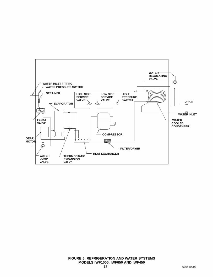
FIGURE 6. REFRIGERATION AND WATER SYSTEMSMODELS IWF1000, IWF650 AND IWF450 13. . . . . . . . . . . . . . . . . . . . . . . . . . . . . . . .
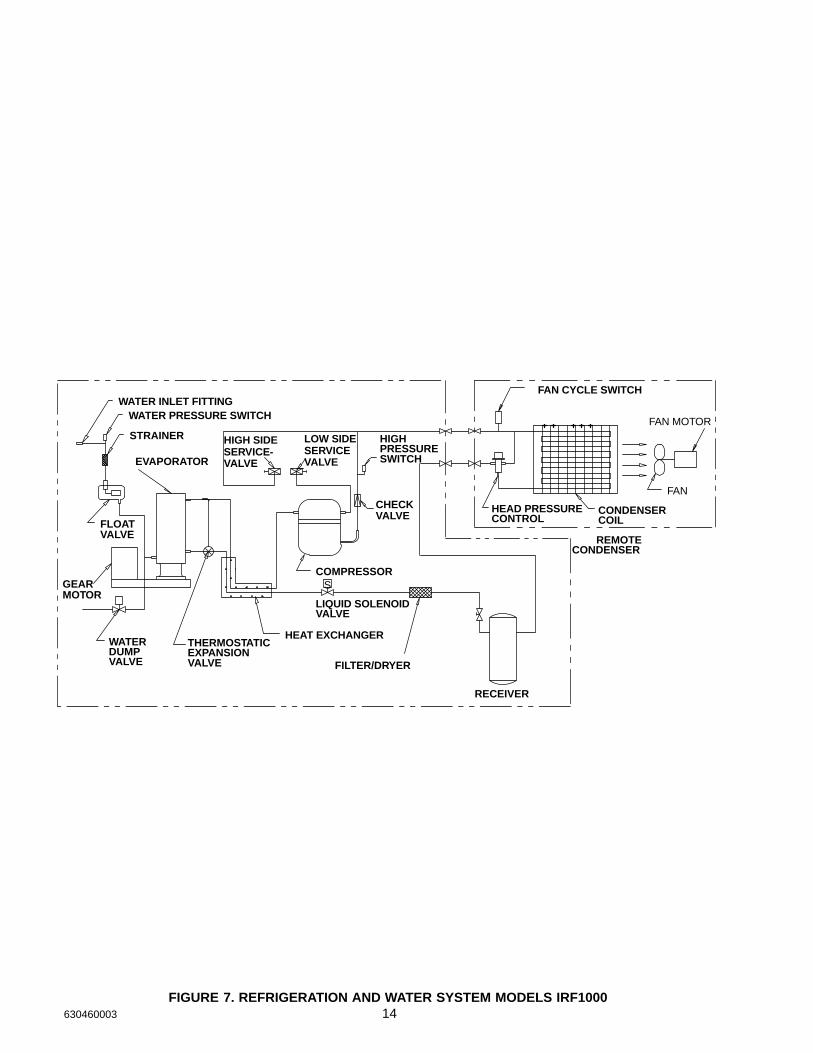
FIGURE 7. REFRIGERATION AND WATER SYSTEM MODELS IRF1000 14. . . . .
FIGURE 8. WIRING DIAGRAM IAF1000 18. . . . . . . . . . . . . . . . . . . . . . . . . . . . . . . . . .
FIGURE 9. WIRING DIAGRAM IWF1000 AND IRF1000 19. . . . . . . . . . . . . . . . . . . .
FIGURE 10. WIRING DIAGRAM IAF650 AND IWF650 20. . . . . . . . . . . . . . . . . . . . . .
1 630460003
INTRODUCTION
We have strived to produce a quality product. The design has been kept simple thus insuring trouble–freeoperation.
This manual has been prepared to assist the Installer.
If you encounter a problem which is not covered in this manual, please feel free to write or call. We will behappy to assist you in any way we can.
When writing, please state the model and serial number of the machine.
Address all correspondence to:
A Product of IMI Cornelius Inc.One Cornelius Place
Anoka, MN 55303–1592
Phone 800–554–3526FAX 612–422–3232PRINTED IN USA
2630460003
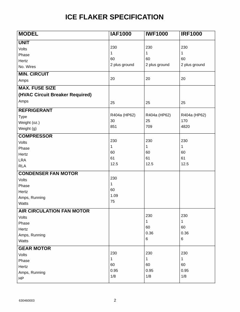
ICE FLAKER SPECIFICATION
MODEL IAF1000 IWF1000 IRF1000
UNITVolts
Phase
Hertz
No. Wires
230
1
60
2 plus ground
230
1
60
2 plus ground
230
1
60
2 plus ground
MIN. CIRCUITAmps 20 20 20
MAX. FUSE SIZE(HVAC Circuit Breaker Required)Amps 25 25 25
REFRIGERANTType
Weight (oz.)
Weight (g)
R404a (HP62)
30
851
R404a (HP62)
25
709
R404a (HP62)
170
4820
COMPRESSORVolts
Phase
Hertz
LRA
RLA
230
1
60
61
12.5
230
1
60
61
12.5
230
1
60
61
12.5
CONDENSER FAN MOTORVolts
Phase
Hertz
Amps, Running
Watts
230
1
60
1.09
75
AIR CIRCULATION FAN MOTORVolts
Phase
Hertz
Amps, Running
Watts
230
1
60
0.36
6
230
1
60
0.36
6
GEAR MOTORVolts
Phase
Hertz
Amps, Running
HP
230
1
60
0.95
1/8
230
1
60
0.95
1/8
230
1
60
0.95
1/8
3 630460003
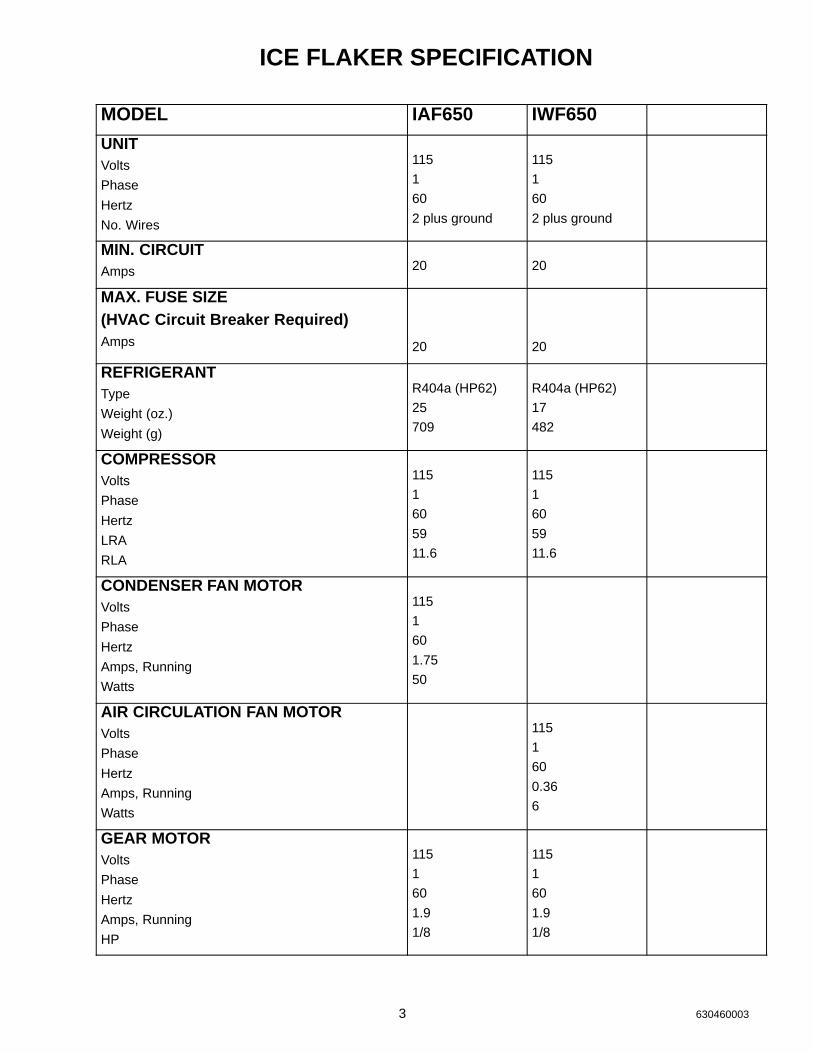
ICE FLAKER SPECIFICATION
MODEL IAF650 IWF650
UNITVolts
Phase
Hertz
No. Wires
115
1
60
2 plus ground
115
1
60
2 plus ground
MIN. CIRCUITAmps 20 20
MAX. FUSE SIZE(HVAC Circuit Breaker Required)Amps 20 20
REFRIGERANTType
Weight (oz.)
Weight (g)
R404a (HP62)
25
709
R404a (HP62)
17
482
COMPRESSORVolts
Phase
Hertz
LRA
RLA
115
1
60
59
11.6
115
1
60
59
11.6
CONDENSER FAN MOTORVolts
Phase
Hertz
Amps, Running
Watts
115
1
60
1.75
50
AIR CIRCULATION FAN MOTORVolts
Phase
Hertz
Amps, Running
Watts
115
1
60
0.36
6
GEAR MOTORVolts
Phase
Hertz
Amps, Running
HP
115
1
60
1.9
1/8
115
1
60
1.9
1/8
4630460003
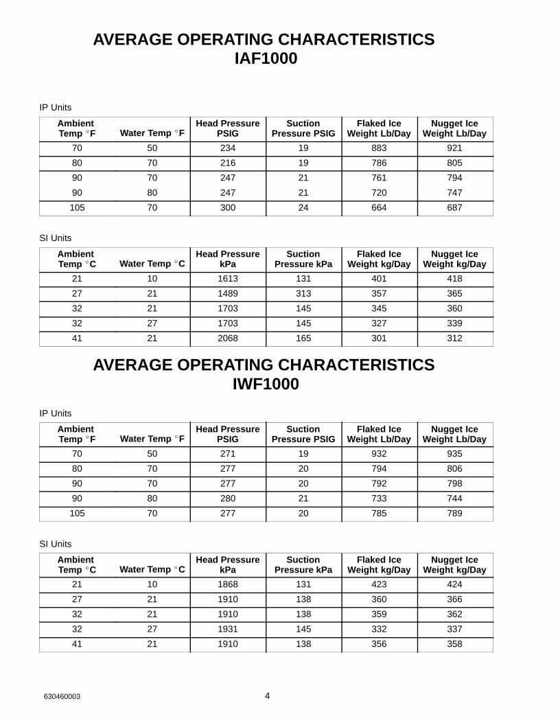
AVERAGE OPERATING CHARACTERISTICS IAF1000
IP Units
Ambient Temp �F Water Temp �F
Head PressurePSIG
SuctionPressure PSIG
Flaked IceWeight Lb/Day
Nugget IceWeight Lb/Day
70 50 234 19 883 921
80 70 216 19 786 805
90 70 247 21 761 794
90 80 247 21 720 747
105 70 300 24 664 687
SI Units
Ambient Temp �C Water Temp �C
Head PressurekPa
SuctionPressure kPa
Flaked IceWeight kg/Day
Nugget IceWeight kg/Day
21 10 1613 131 401 418
27 21 1489 313 357 365
32 21 1703 145 345 360
32 27 1703 145 327 339
41 21 2068 165 301 312
AVERAGE OPERATING CHARACTERISTICS IWF1000
IP Units
Ambient Temp �F Water Temp �F
Head PressurePSIG
SuctionPressure PSIG
Flaked IceWeight Lb/Day
Nugget IceWeight Lb/Day
70 50 271 19 932 935
80 70 277 20 794 806
90 70 277 20 792 798
90 80 280 21 733 744
105 70 277 20 785 789
SI Units
Ambient Temp �C Water Temp �C
Head PressurekPa
SuctionPressure kPa
Flaked IceWeight kg/Day
Nugget IceWeight kg/Day
21 10 1868 131 423 424
27 21 1910 138 360 366
32 21 1910 138 359 362
32 27 1931 145 332 337
41 21 1910 138 356 358
5 630460003
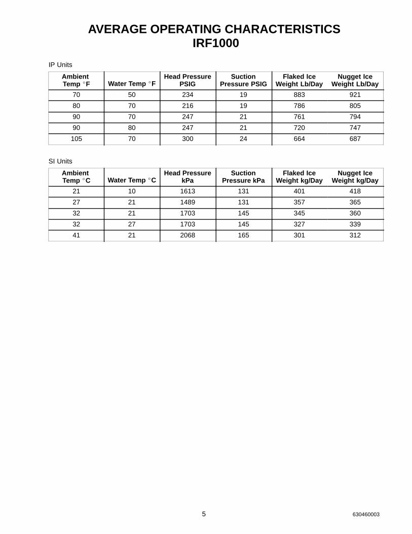
AVERAGE OPERATING CHARACTERISTICS IRF1000
IP Units
Ambient Temp �F Water Temp �F
Head PressurePSIG
SuctionPressure PSIG
Flaked IceWeight Lb/Day
Nugget IceWeight Lb/Day
70 50 234 19 883 921
80 70 216 19 786 805
90 70 247 21 761 794
90 80 247 21 720 747
105 70 300 24 664 687
SI Units
Ambient Temp �C Water Temp �C
Head PressurekPa
SuctionPressure kPa
Flaked IceWeight kg/Day
Nugget IceWeight kg/Day
21 10 1613 131 401 418
27 21 1489 131 357 365
32 21 1703 145 345 360
32 27 1703 145 327 339
41 21 2068 165 301 312
6630460003
INSTALLATION INSTRUCTIONS
You will get better service from the ice machine, longer life and greater convenience if you choose its locationwith care. Select a location as close as possible to where the highest volume of ice will used.
Here are a few points to consider:
1. Select a location as close as possible to where you are going to use the most ice.
2. Allow a minimum of 6” space at sides and rear of machine for ventilation.
3. A kitchen installation is not desirable as a rule. If a kitchen installation is necessary, locate the machine asfar away from the cooking area as possible. Grease laden air will form a greasy deposit on the condenser.This reduces the ice making efficiency and necessitates thorough cleaning quite often.
4. If you install the unit in a storeroom, be sure the room is well ventilated.
NOTE: Do not install where the ambient and incoming water temperature will drop below 50� F or riseto over 100� F.
WARNING: If water pressure exceeds 50 pounds, a water pressure regulator should beinstalled in water inlet line between water shut–off valve and strainer. Minimum incomingwater pressure required is 22 pounds.
5. Uncrate the unit by cutting the lower band on the carton and lift the carton off the unit.
6. All “I” series flakers are supplied with bin sealing gasket material. Install the gasket around the bottomoutside edge of the unit by removed the protective paper and pressing in place.
7. Uncrate the ice storage bin and set in place. Connect a drain hose to the bin and level the bin. Install anyrequired bin adapter(s) at this time.
8. Carefully place the flaker on the bin. Be careful not to damage the flaker gasket material.
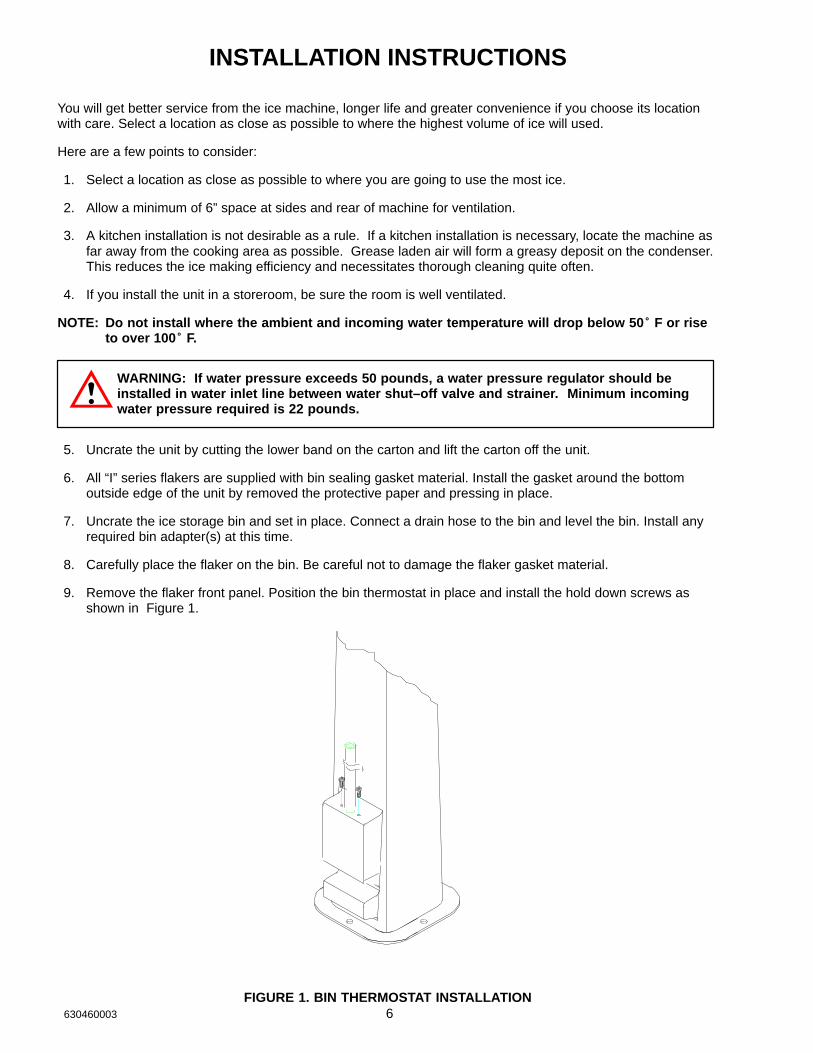
9. Remove the flaker front panel. Position the bin thermostat in place and install the hold down screws asshown in Figure 1.
FIGURE 1. BIN THERMOSTAT INSTALLATION
7 630460003
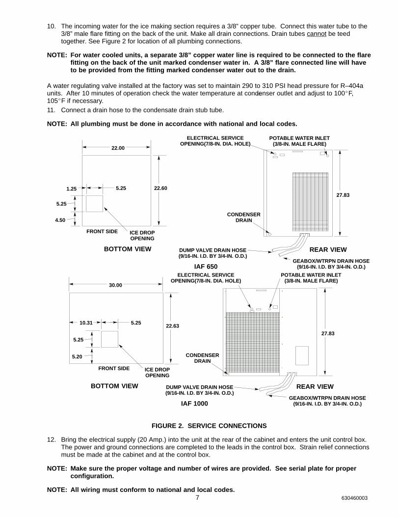
10. The incoming water for the ice making section requires a 3/8” copper tube. Connect this water tube to the3/8” male flare fitting on the back of the unit. Make all drain connections. Drain tubes cannot be teedtogether. See Figure 2 for location of all plumbing connections.
NOTE: For water cooled units, a separate 3/8” copper water line is required to be connected to the flarefitting on the back of the unit marked condenser water in. A 3/8” flare connected line will haveto be provided from the fitting marked condenser water out to the drain.
A water regulating valve installed at the factory was set to maintain 290 to 310 PSI head pressure for R–404aunits. After 10 minutes of operation check the water temperature at condenser outlet and adjust to 100�F, 105�F if necessary.11. Connect a drain hose to the condensate drain stub tube.
NOTE: All plumbing must be done in accordance with national and local codes.
22.00
1.25 5.25
5.25
4.50
22.6027.83
FRONT SIDE ICE DROPOPENING
ELECTRICAL SERVICEOPENING(7/8-IN. DIA. HOLE)
POTABLE WATER INLET(3/8-IN. MALE FLARE)
CONDENSERDRAIN
DUMP VALVE DRAIN HOSE(9/16-IN. I.D. BY 3/4-IN. O.D.)
GEABOX/WTRPN DRAIN HOSE(9/16-IN. I.D. BY 3/4-IN. O.D.)
BOTTOM VIEW REAR VIEW
IAF 650
ill371
30.00
10.31 5.25
5.25
5.20
22.6327.83
FRONT SIDE ICE DROPOPENING
ELECTRICAL SERVICEOPENING(7/8-IN. DIA. HOLE)
POTABLE WATER INLET(3/8-IN. MALE FLARE)
CONDENSERDRAIN
DUMP VALVE DRAIN HOSE(9/16-IN. I.D. BY 3/4-IN. O.D.)
GEABOX/WTRPN DRAIN HOSE(9/16-IN. I.D. BY 3/4-IN. O.D.)
BOTTOM VIEW REAR VIEW
IAF 1000
FIGURE 2. SERVICE CONNECTIONS
12. Bring the electrical supply (20 Amp.) into the unit at the rear of the cabinet and enters the unit control box.The power and ground connections are completed to the leads in the control box. Strain relief connectionsmust be made at the cabinet and at the control box.
NOTE: Make sure the proper voltage and number of wires are provided. See serial plate for properconfiguration.
NOTE: All wiring must conform to national and local codes.
8630460003
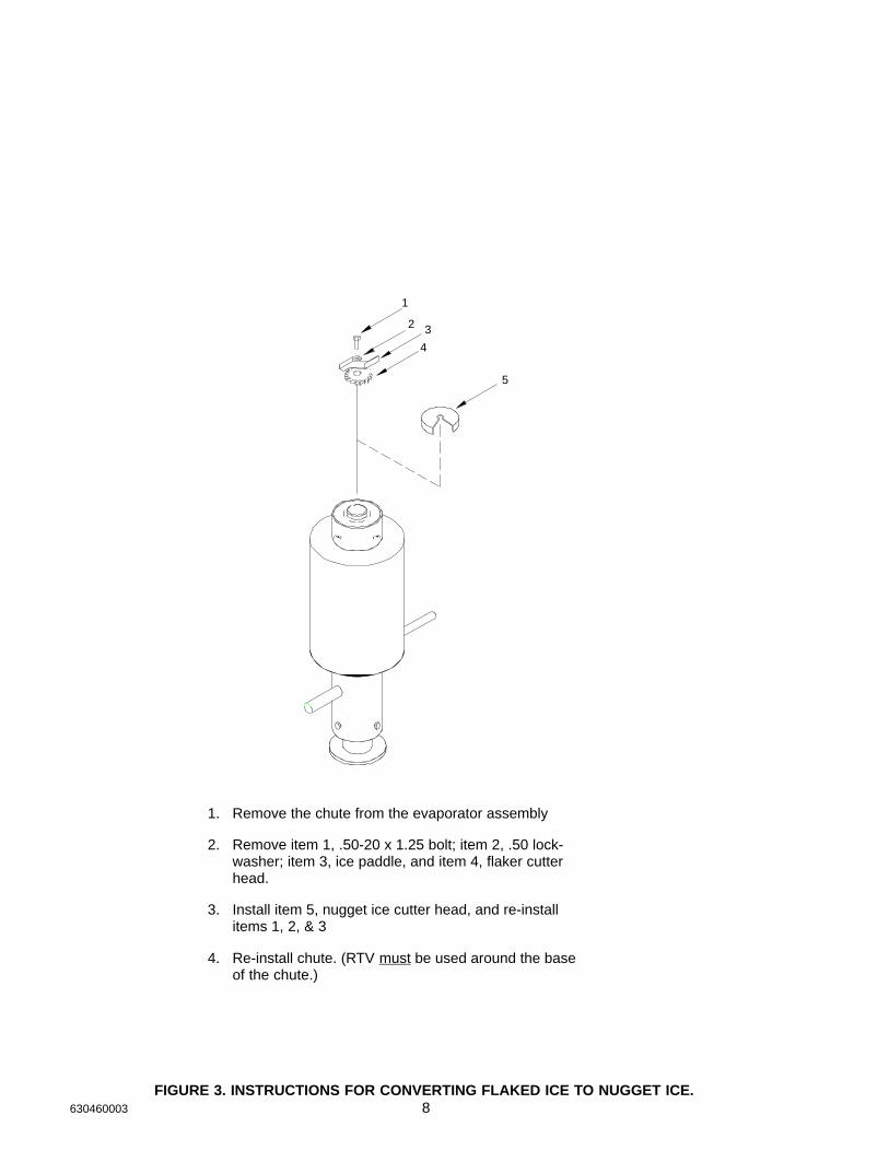
1. Remove the chute from the evaporator assembly
2. Remove item 1, .50-20 x 1.25 bolt; item 2, .50 lock-washer; item 3, ice paddle, and item 4, flaker cutterhead.
3. Install item 5, nugget ice cutter head, and re-installitems 1, 2, & 3
4. Re-install chute. (RTV must be used around the baseof the chute.)
3
4
5
1
2
FIGURE 3. INSTRUCTIONS FOR CONVERTING FLAKED ICE TO NUGGET ICE.
9 630460003
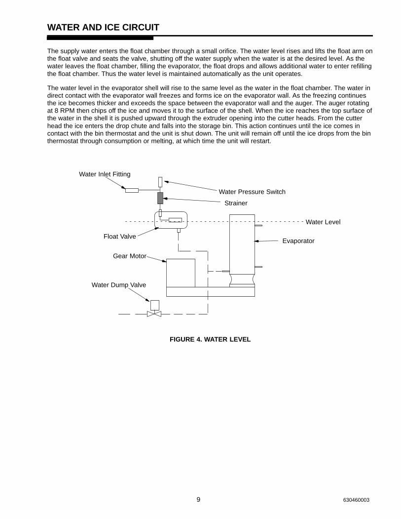
WATER AND ICE CIRCUIT
The supply water enters the float chamber through a small orifice. The water level rises and lifts the float arm onthe float valve and seats the valve, shutting off the water supply when the water is at the desired level. As thewater leaves the float chamber, filling the evaporator, the float drops and allows additional water to enter refillingthe float chamber. Thus the water level is maintained automatically as the unit operates.
The water level in the evaporator shell will rise to the same level as the water in the float chamber. The water indirect contact with the evaporator wall freezes and forms ice on the evaporator wall. As the freezing continuesthe ice becomes thicker and exceeds the space between the evaporator wall and the auger. The auger rotatingat 8 RPM then chips off the ice and moves it to the surface of the shell. When the ice reaches the top surface ofthe water in the shell it is pushed upward through the extruder opening into the cutter heads. From the cutterhead the ice enters the drop chute and falls into the storage bin. This action continues until the ice comes incontact with the bin thermostat and the unit is shut down. The unit will remain off until the ice drops from the binthermostat through consumption or melting, at which time the unit will restart.
Water Level
Water Inlet Fitting
Water Pressure Switch
Strainer
Gear Motor
Float Valve
Water Dump Valve
Evaporator
FIGURE 4. WATER LEVEL
10630460003
ELECTRICAL CIRCUIT
CIRCUIT DESCRIPTION
As the manual on-off-circuit breaker switch is pushed to ”on”, an electrical circuit is completed to the gearmotorvia the circuit breaker gearmotor overload, power relay / contactor, gearmotor delay thermostat and the binthermostat. After the previous circuit has been completed the fan motor will start when the head pressurereaches 270 PSI and will cycle off at 205 PSI. The compressor will start via the high pressure control and thecompressor starting relay.
COMPONENT DESCRIPTION
BIN THERMOSTAT
This is electrically in ”series” with the ice making system. when the bin is full, the contact opens, terminatingpower to the machine.
CAUTION: Setting the bin thermostat to the coldest position may cause excessive icebuild-up in the chute and it can possibly cause the chute to pop-off from ice build-up.
GEARMOTOR START RELAY
This is a current type relay which means as the gearmotor run winding comes ”on” the line, the current drawinitially is relatively heavy through the relay coil (coil is in series with run winding). It then acts like a normalrelay and the N.O. start contact ”makes”, completing a circuit through the start capacitor to the start winding.As the gearmotor picks up speed, the amp draw through the relay coil drops off allowing the armature to returnto its normal position (start contact ”opens”). This action removes the start winding from the circuit.
COMPRESSOR CONTACTOR
Controls the compressor input power only.
GEARMOTOR DELAY THERMOSTAT
The purpose of the Delay Thermostat is to allow an electrical path to the gearmotor for continuous operation toclear the evaporator of ice to prevent auger freeze up. As the ice from the evaporator is augered up, the suctionline of the evaporator will warm-up causing the Delay Thermostat to open, cancelling the gearmotor electricalcircuit.
CAUTION: The Delay Thermostat must be insulated to prevent biasing action of room and compressor areatemperatures.
This thermostat keeps the gearmotor running until the suction line temperature reaches 45� F after the binthermostat terminates power to the contactor.
ON–OFF SWITCH / CIRCUIT BREAKER
This switch interrupts power to the entire unit. The switch has a circuit breaker incorporated into its’ design.This circuit breaker will trip out in the event the gearmotor draws to high of amps In such an event the power isinterrupted to the unit. To reset the circuit breaker and reestablish power to the unit, push the switch to the ”off”position and then back to the ”on” position.
11 630460003
FAN CYCLING SWITCH (R404a Units)
The function of this switch is to maintain condensing pressures at a satisfactory level during–low ambientconditions. The switch breaks the circuit to the condenser fan motor at 205 PSI and makes the circuit at 275PSI.
HIGH PRESSURE CONTROL
The high pressure cut out is electrically in series with the contactor. As the head pressure rises to 450 PSIG,for R404a charged units, a preset level the contact opens thus breaking the circuit to the compressor via thecontactor. This control must be reset manually on R404a units.
COMPRESSOR START RELAY
This is a current type relay and contains a N.O. contact which is connected in series with the start winding of thecompressor. The relay coil is electrically in series with the run winding. When power is applied, the compressordraws high current which sets up a magnetic field around the magnet coil which causes the relay to operate,closing the relay contact. As the compressor approaches operating speed, the current flowing through the coildecreases, permitting the relay contact to open, thereby opening the starting circuit.
POTENTIAL RELAYS
The potential relay is used as a compressor starting relay, The contact in the potential relay is N.C.. Themagnet coil is connected across (parallel) the start winding and is affected by induced voltage, generated by thestart winding. As the compressor comes up to design speed, the voltage across the relay coil increases and atrunning speed is sometimes as much as 2 1/2 times the supply voltage. This voltage sets up a magnetic fieldwhich causes the relay to operate. The starting relay is calibrated to remove the start capacitor (open thestarting circuit) at approximately 80% of the compressor operating speed.
NOTE: BOTH TYPES OF RELAYS ARE DESIGNED TO OPERATE WITHIN VERY NARROW LIMITS OFVOLTAGE AND CURRENT DICTATED BY MOTOR DESIGN, THEREFORE, WHEN MAKING AREPLACEMENT OF A RELAY ALWAYS PROVIDE AN EXACT REPLACEMENT RECOMMENDEDBY THE COMPRESSOR MANUFACTURER.
CAPACITORS – GENERAL
An electrical capacitor is a device which stores up electrical energy. Capacitors are used with single phasemotors to provide starting torque and improve running characteristics; by feeding this energy to the start windingin step with the run winding.
Any capacitor has three (3) essential parts, two (2) of which are usually foil plates separated and insulated bythe third part called the dielectric.
Two general types of capacitors are used with electric motors. The electrolytic starting capacitor usually uses avery thin film of oxide on the metallic plate as the dielectric. The running capacitor usually is of the liquid filledtype. and remains in the circuit during both the start and run operation.
DUMP SWITCH
This switch activates the evaporator dump valve manually. This allows the draining of the evaporator for serviceor cleaning. Dumping the water every 24 or 48 hours will reduce the down time for cleaning in high mineralcontent water areas.
12630460003
WATER INLET FITTING
VALVE
COOLEDAIR
CONDENSER
FANCYCLESWITCH
SWITCHPRESSUREHIGH
MOTORGEAR
FLOAT
EVAPORATOR
VALVE
WATERDUMP EXPANSION
VALVE
THERMOSTATICHEAT EXCHANGER
FAN MOTOR
FAN
LOW SIDESERVICEVALVEVALVE
SERVICEHIGH SIDE
COMPRESSOR
FILTER/DRYER
STRAINER
WATER PRESSURE SWITCH
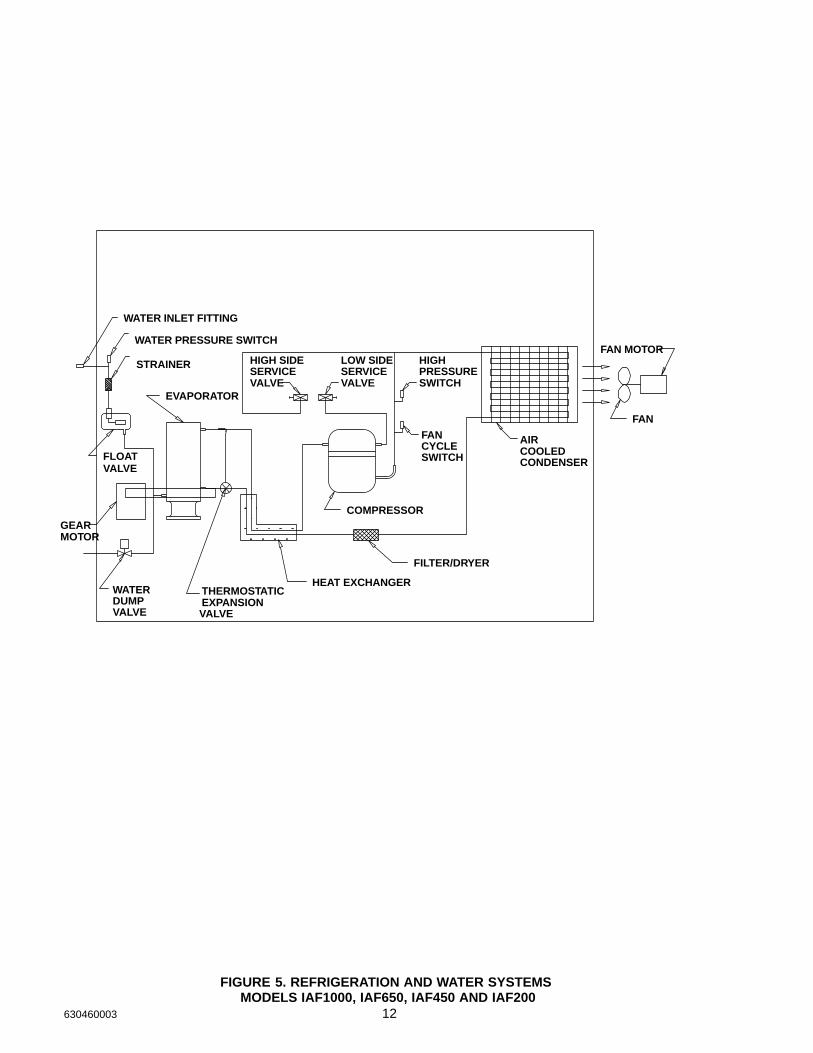
FIGURE 5. REFRIGERATION AND WATER SYSTEMS MODELS IAF1000, IAF650, IAF450 AND IAF200
13 630460003
REGULATINGVALVE
WATER
WATER INLET
DRAIN
COOLEDCONDENSER
WATER
WATER INLET FITTING
VALVE
SWITCHPRESSUREHIGH
MOTORGEAR
FLOAT
EVAPORATOR
VALVE
WATERDUMP EXPANSION
VALVE
THERMOSTATICHEAT EXCHANGER
LOW SIDESERVICEVALVEVALVE
SERVICEHIGH SIDE
COMPRESSOR
FILTER/DRYER
STRAINER
WATER PRESSURE SWITCH
FIGURE 6. REFRIGERATION AND WATER SYSTEMSMODELS IWF1000, IWF650 AND IWF450
14630460003
S
CONDENSERREMOTE
FAN CYCLE SWITCH
CONTROLHEAD PRESSURE
VALVECHECK
RECEIVER
VALVELIQUID SOLENOID
WATER INLET FITTING
VALVECOILCONDENSER
SWITCHPRESSUREHIGH
MOTORGEAR
FLOAT
EVAPORATOR
VALVE
WATERDUMP EXPANSION
VALVE
THERMOSTATICHEAT EXCHANGER
FAN MOTOR
FAN
LOW SIDESERVICEVALVE
HIGH SIDE SERVICE-VALVE
COMPRESSOR
FILTER/DRYER
STRAINER
WATER PRESSURE SWITCH
FIGURE 7. REFRIGERATION AND WATER SYSTEM MODELS IRF1000
15 630460003
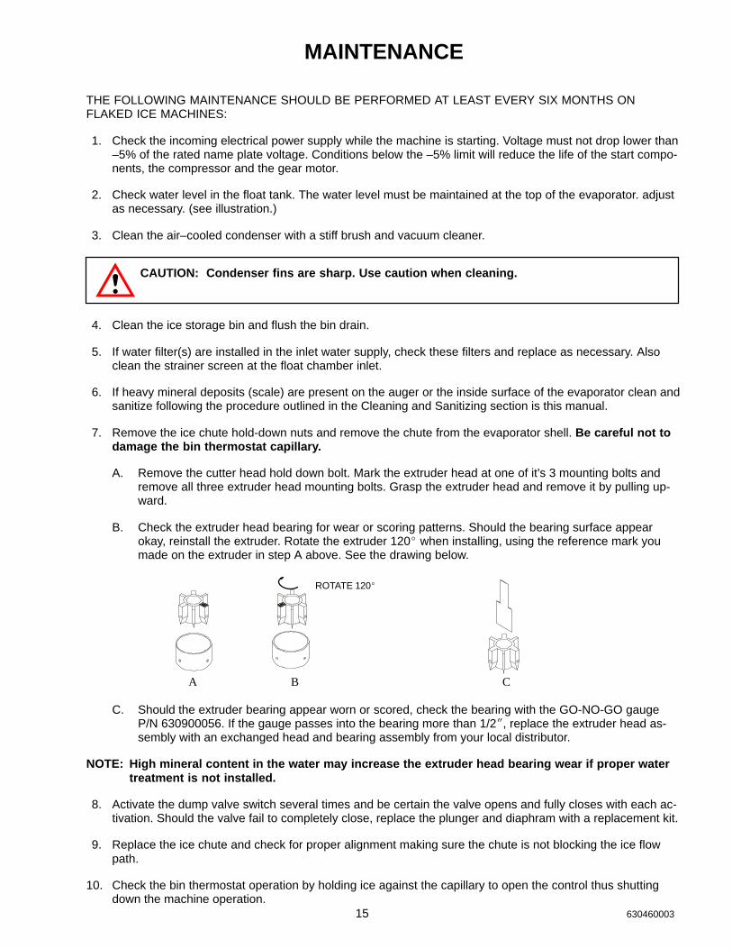
MAINTENANCE
THE FOLLOWING MAINTENANCE SHOULD BE PERFORMED AT LEAST EVERY SIX MONTHS ONFLAKED ICE MACHINES:
1. Check the incoming electrical power supply while the machine is starting. Voltage must not drop lower than–5% of the rated name plate voltage. Conditions below the –5% limit will reduce the life of the start compo-nents, the compressor and the gear motor.
2. Check water level in the float tank. The water level must be maintained at the top of the evaporator. adjustas necessary. (see illustration.)
3. Clean the air–cooled condenser with a stiff brush and vacuum cleaner.
CAUTION: Condenser fins are sharp. Use caution when cleaning.
4. Clean the ice storage bin and flush the bin drain.
5. If water filter(s) are installed in the inlet water supply, check these filters and replace as necessary. Alsoclean the strainer screen at the float chamber inlet.
6. If heavy mineral deposits (scale) are present on the auger or the inside surface of the evaporator clean andsanitize following the procedure outlined in the Cleaning and Sanitizing section is this manual.
7. Remove the ice chute hold-down nuts and remove the chute from the evaporator shell. Be careful not todamage the bin thermostat capillary.
A. Remove the cutter head hold down bolt. Mark the extruder head at one of it’s 3 mounting bolts andremove all three extruder head mounting bolts. Grasp the extruder head and remove it by pulling up-ward.
B. Check the extruder head bearing for wear or scoring patterns. Should the bearing surface appearokay, reinstall the extruder. Rotate the extruder 120� when installing, using the reference mark youmade on the extruder in step A above. See the drawing below.
ROTATE 120�
A B C
C. Should the extruder bearing appear worn or scored, check the bearing with the GO-NO-GO gaugeP/N 630900056. If the gauge passes into the bearing more than 1/2�, replace the extruder head as-sembly with an exchanged head and bearing assembly from your local distributor.
NOTE: High mineral content in the water may increase the extruder head bearing wear if proper watertreatment is not installed.
8. Activate the dump valve switch several times and be certain the valve opens and fully closes with each ac-tivation. Should the valve fail to completely close, replace the plunger and diaphram with a replacement kit.
9. Replace the ice chute and check for proper alignment making sure the chute is not blocking the ice flowpath.
10. Check the bin thermostat operation by holding ice against the capillary to open the control thus shuttingdown the machine operation.
16630460003
“I” SERIES FLAKER CLEANING AND SANITIZING PROCEDURE
1. To eliminate water from entering the reservoir, block up the float located inside the reservoir, activate thedump switch to the “ON” position and turn the power switch to “ON”. Allow the evaporator to drain. Turn thepower switch to the “OFF” position.
2. Remove the ice chute by removing the hold-down nuts at the base and the self-clamping bolt at the top. Liftthe chute clear of the evaporator assembly.
3. Return the float to it’s normal position. As the float chamber refills with water and fills the evaporator, add 3oz. of Calgon Nickel-Safe ice machine cleaner to the float chamber. (Gravity will feed the cleaner to theevaporator.)
NOTE: Do not remove the auger, extruder head, or other parts from the evaporator assembly.
4. Allow the cleaning solution to stand in the evaporator for 20 - 30 minutes. Block up the float and drain theevaporator as in step 1.
5. Rinse/flush by carefully filling with warm water (100�F) and drain by following step 1 again. Repeat at least3 times. During the final rinse/flush cycle, add 1 tablespoon of regular Baking Soda and allow it to stand for10 - 15 minutes.
6. Drain the evaporator and rinse/flush one more time.
7. Install the ice chute and panels. (RTV must be used around the base of the chute.)
CAUTION: Should sanitizing be required, DO NOT use a mixture of household bleach andwater Chlorine will attack stainless steel. Use only a commercial ice machine sanitizer suchas Calgon Sanitizer for ice machines, following the directions on the container.
NOTE: When cleaning and/or sanitizing is complete return the machine back to an ice making cycle.Discard the first 30 minutes of ice production. DO NOT allow any ice that has been in contactwith sanitizer to ever be used.
17 630460003
WATER TREATMENT
During the freezing process, as water passes over the evaporator, the impurities in the water have a tendencyto be rejected and the plate will freeze only the pure water.
However, the more dissolved solids in the water, the more troublesome the freezing operation will be. Bicarbon-ates in the water are the most troublesome of the impurities. These impurities will cause scaling on the evapo-rator, clogging of the float valve mechanism and other parts in the water system. If the concentration of impuri-ties is high, mushy ice may be the result.
Parts of the Flaker, that are in contact with the water or ice, may corrode if the water is high in acidity. In someareas, water may have to be treated in order to overcome some of the problems that arise because of the min-eral content.
IMI Cornelius has water filter/treatment systems available to control impurities found in most water supplies.Contact your local dealer for more information.
WINTER STORAGE
If the unit is to be stored in an area where the temperature will drop below freezing, it is most important that allwater lines be drained to prevent them from freezing and possible rupture.
To blow out the water line, disconnect the water supply at the cabinet inlet and use air pressure to force the wa-ter into the water reservoir pan, it can then be removed from the water pan.
WATER COOLED CONDENSER – To remove water from condenser unhook water supply and attach com-pressed air hose. Start machine. As head pressure reaches the appropriate level opening the water regulatingvalve, the compressed air will force the water out. Do not let the machine operate longer than necessary.
CLEANING THE CONDENSER (AIR COOLED)
In order to produce at full capacity, the refrigeration condenser must be kept clean. The frequency of cleaningwill be determined by surrounding condition. A good maintenance plan calls for an inspection at least every twomonths.
With a vacuum cleaner, remove all accumulated dust and lint that has adhered to the finned condenser at therear of the unit. The use of a stiff bristle brush may be helpful.
CAUTION: CONDENSER COOLING FINS ARE SHARP. USE CARE WHEN CLEANING.
18630460003
��
��
��
��
��
��
��
������� ��������� ����
������������
������������
� �
��
��
����
������ ���
�����
���� ����
�
����
������ ���
��������
�������������
�
��
����
�� ������
�� �������
������
�����
��
����
��
��
�� ����
������������
�����������
�
�
�
�
��
�
����������
�� � ���
�
�
����
�!
��
�
��
��
��
����������
���
�
����� ���������
���������������
����
����������
� ����������
�����
���������
��
�
���������
��
����������
��
� ����������
�
��
�
��
�
������������
����������
����������
�
��"!������������#���$
��������
������
�
��
�
��
�� ������
�
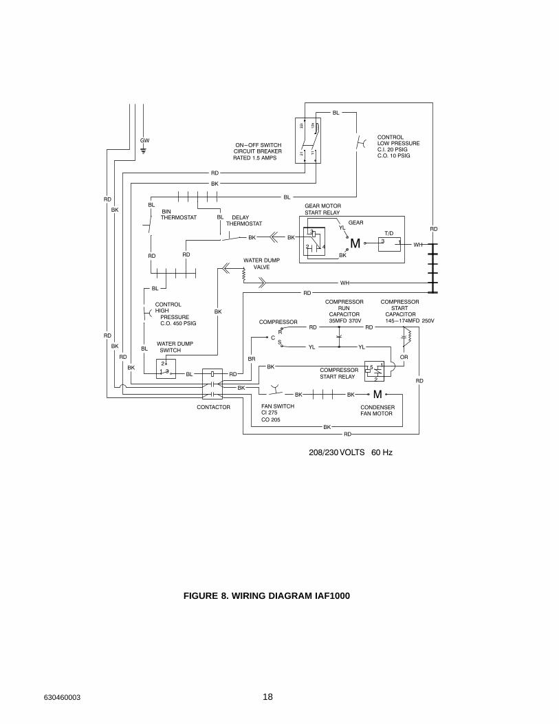
FIGURE 8. WIRING DIAGRAM IAF1000
19 630460003
GW
RD
BK
RD
BK
RD
BKBL
BL
RD
BL
RD
BK
BK
BK
BL
BK
BK BK
WH
RD
RD RD
YL YL
BK
BK
RD RD
RD
RD
BL
BL
RD
BK
RDBR
OR
BK
YL
BK BKWH
Crankcase Heater(IRF Only)
ON-OFF SwitchCircuit BreakerRated 1.5 Amps
ControlLow PressureCI 20 PSIGCO 10 PSIG
BinThermostat
DelayThermostat
Gear MotorStart Relay
T/D
Cooling FanMotorWater Dump
ValveControlHigh PressureCO 450 PSIG
Water DumpSwitch
Contactor
Liquid LineSolenoid(IRF Only)
CompressorStart Relay
Compressor
CR
S
Compressor RunCapacitor35MFD 370 V
Compressor StartCapacitor145-174MFD 250 V
12
3
M
M
BL
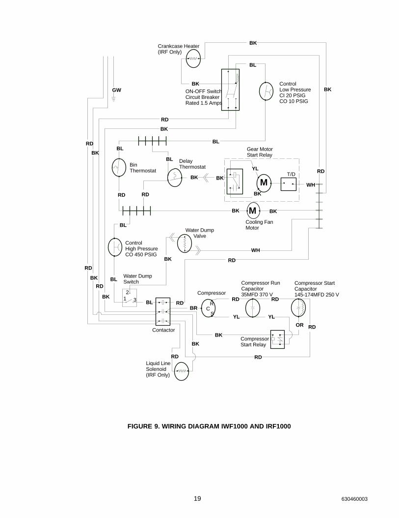
FIGURE 9. WIRING DIAGRAM IWF1000 AND IRF1000
20630460003
CONTACTOR
HIGHPRESSURE
1
COMPRESSOR
COMPRESSORSTART RELAY 2
5
CS
R
COMPRESSOR
COMPRESSORRUN
CAPACITOR CAPACITORSTART
ON–OFF SWITCH
THERMOSTATDELAY
CIRCUIT BREAKER RATED 2.0 AMPS
BINTHERMOSTAT
21 11
T/D
GEAR
M
GEAR MOTOR
42
3
22i
12k
START RELAY
LOW PRESSURECONTROL
3 1
C.O. 450 PSIG
SWITCHWATER DUMP
12
CONTROL
VALVEWATER DUMP
C.I. 20 PSIGC.O. 10 PSIG
30MFD 440V
YL
BK
M
FAN MOTORCOOLING
IWF ONLY
M
LOW AMBIENTSWITCH (A/C ONLY)
CI275 C0205
(A/C ONLY)CONDENSOR FAN MOTOR
BK
BK
WH
YL
RD RD
YL
OR
WH
BKBL
BK
GW
WH
BK
WH
BL
BK
WH
BR
WH
BL
BL
BK
RDRD
BL
BR
BL
WH
BK
WH
BK
WHBL
BKBKBKBL
BK
WH
BK
3
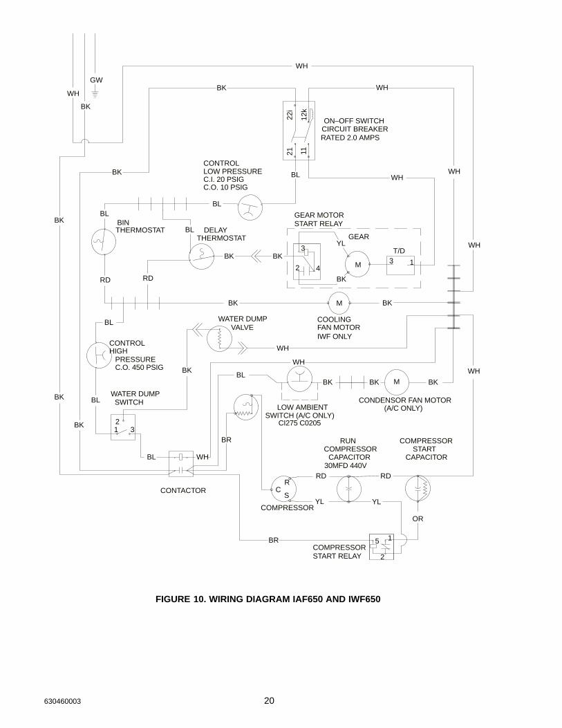
FIGURE 10. WIRING DIAGRAM IAF650 AND IWF650
21 630460003
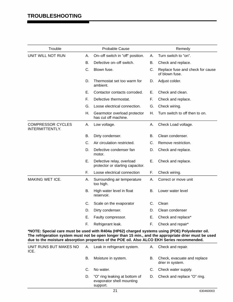
TROUBLESHOOTING
Trouble Probable Cause Remedy
UNIT WILL NOT RUN A. On–off switch in ”off” position. A. Turn switch to ”on”.
B. Defective on–off switch. B. Check and replace.
C. Blown fuse. C. Replace fuse and check for causeof blown fuse.
D. Thermostat set too warm forambient.
D. Adjust colder.
E. Contactor contacts corroded. E. Check and clean.
F. Defective thermostat. F. Check and replace.
G. Loose electrical connection. G. Check wiring.
H. Gearmotor overload protectorhas cut off machine.
H. Turn switch to off then to on.
COMPRESSOR CYCLESINTERMITTENTLY.
A. Low voltage. A. Check Load voltage.
B. Dirty condenser. B. Clean condenser.
C. Air circulation restricted. C. Remove restriction.
D. Defective condenser fanmotor.
D. Check and replace.
E. Defective relay, overloadprotector or starting capacitor.
E. Check and replace.
F. Loose electrical connection F. Check wiring.
MAKING WET ICE. A. Surrounding air temperaturetoo high.
A. Correct or move unit
B. High water level in floatreservoir.
C. Scale on the evaporator
B. Lower water level
C. Clean
D. Dirty condenser. D. Clean condenser
E. Faulty compressor. E. Check and replace*
F. Refrigerant leak. F. Check and repair*
*NOTE: Special care must be used with R404a (HP62) charged systems using (POE) Polyolester oil.The refrigeration system must not be open longer than 15 min., and the appropriate drier must be useddue to the moisture absorption properties of the POE oil. Also ALCO EKH Series recommended.
UNIT RUNS BUT MAKES NOICE.
A. Leak in refrigerant system. A. Check and repair.
B. Moisture in system. B. Check, evacuate and replacedrier in system.
C. No water. C. Check water supply.
D. ”O” ring leaking at bottom ofevaporator shell mountingsupport.
D. Check and replace ”O” ring.
22630460003
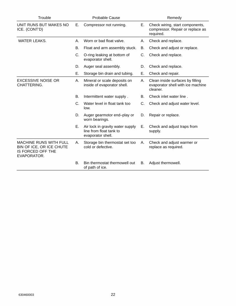
Trouble RemedyProbable Cause
UNIT RUNS BUT MAKES NOICE. (CONT’D)
E. Compressor not running. E. Check wiring, start components,compressor. Repair or replace asrequired.
WATER LEAKS. A. Worn or bad float valve. A. Check and replace.
B. Float and arm assembly stuck. B. Check and adjust or replace.
C. O-ring leaking at bottom ofevaporator shell.
C. Check and replace.
D. Auger seal assembly. D. Check and replace.
E. Storage bin drain and tubing. E. Check and repair.
EXCESSIVE NOISE ORCHATTERING.
A. Mineral or scale deposits oninside of evaporator shell.
A. Clean inside surfaces by fillingevaporator shell with ice machinecleaner.
B. Intermittent water supply . B. Check inlet water line .
C. Water level in float tank toolow.
C. Check and adjust water level.
D. Auger gearmotor end–play orworn bearings.
D. Repair or replace.
E. Air lock in gravity water supplyline from float tank toevaporator shell.
E. Check and adjust traps fromsupply.
MACHINE RUNS WITH FULLBIN OF ICE, OR ICE CHUTEIS FORCED OFF THEEVAPORATOR.
A. Storage bin thermostat set toocold or defective.
A. Check and adjust warmer orreplace as required.
B. Bin thermostat thermowell outof path of ice.
B. Adjust thermowell.
23 630460003
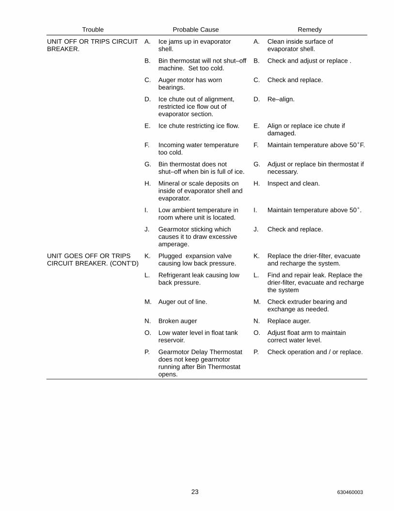
Trouble RemedyProbable Cause
UNIT OFF OR TRIPS CIRCUITBREAKER.
A. Ice jams up in evaporatorshell.
A. Clean inside surface ofevaporator shell.
B. Bin thermostat will not shut–offmachine. Set too cold.
B. Check and adjust or replace .
C. Auger motor has wornbearings.
C. Check and replace.
D. Ice chute out of alignment,restricted ice flow out ofevaporator section.
D. Re–align.
E. Ice chute restricting ice flow. E. Align or replace ice chute ifdamaged.
F. Incoming water temperaturetoo cold.
F. Maintain temperature above 50�F.
G. Bin thermostat does notshut–off when bin is full of ice.
G. Adjust or replace bin thermostat ifnecessary.
H. Mineral or scale deposits oninside of evaporator shell andevaporator.
H. Inspect and clean.
I. Low ambient temperature inroom where unit is located.
I. Maintain temperature above 50��
J. Gearmotor sticking whichcauses it to draw excessiveamperage.
J. Check and replace.
UNIT GOES OFF OR TRIPSCIRCUIT BREAKER. (CONT’D)
K. Plugged expansion valvecausing low back pressure.
K. Replace the drier-filter, evacuateand recharge the system.
L. Refrigerant leak causing lowback pressure.
L. Find and repair leak. Replace thedrier-filter, evacuate and rechargethe system
M. Auger out of line. M. Check extruder bearing andexchange as needed.
N. Broken auger N. Replace auger.
O. Low water level in float tankreservoir.
O. Adjust float arm to maintaincorrect water level.
P. Gearmotor Delay Thermostatdoes not keep gearmotorrunning after Bin Thermostatopens.
P. Check operation and / or replace.

24630460003
“I” Series “Remote”
Ice Machine

25 630460003
26 630460003
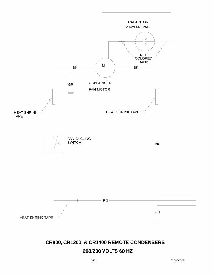
BK
CAPACITOR
RED
2 mfd 440 VAC
BK
GR
��������������� �
BK
GR
FAN CYCLINGSWITCH
RD
M
FAN MOTOR
CONDENSER
CR800, CR1200, & CR1400 REMOTE CONDENSERS
HEAT SHRINK TAPEHEAT SHRINKTAPE
HEAT SHRINK TAPE
COLOREDBAND
27 630460003
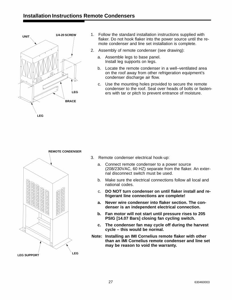
Installation Instructions Remote Condensers
1. Follow the standard installation instructions supplied withflaker. Do not hook flaker into the power source until the re-mote condenser and line set installation is complete.
2. Assembly of remote condenser (see drawing):
a. Assemble legs to base panel.Install leg supports on legs.
b. Locate the remote condenser in a well–ventilated areaon the roof away from other refrigeration equipment’scondenser discharge air flow.
c. Use the mounting holes provided to secure the remotecondenser to the roof. Seal over heads of bolts or fasten-ers with tar or pitch to prevent entrance of moisture.
3. Remote condenser electrical hook-up:
a. Connect remote condenser to a power source(208/230VAC, 60 HZ) separate from the flaker. An exter-nal disconnect switch must be used.
b. Make sure the electrical connections follow all local and national codes.
c. DO NOT turn condenser on until flaker install and re-frigerant line connections are complete!
a. Never wire condenser into flaker section. The con-denser is an independent electrical connection.
b. Fan motor will not start until pressure rises to 205PSIG [14.07 Bars] closing fan cycling switch.
c. The condenser fan may cycle off during the harvestcycle – this would be normal.
Note: Installing an IMI Cornelius remote flaker with otherthan an IMI Cornelius remote condenser and line setmay be reason to void the warranty.
UNIT 1/4-20 SCREW
LEG
BRACE
LEG
REMOTE CONDENSER
LEGLEG SUPPORT
28630460003
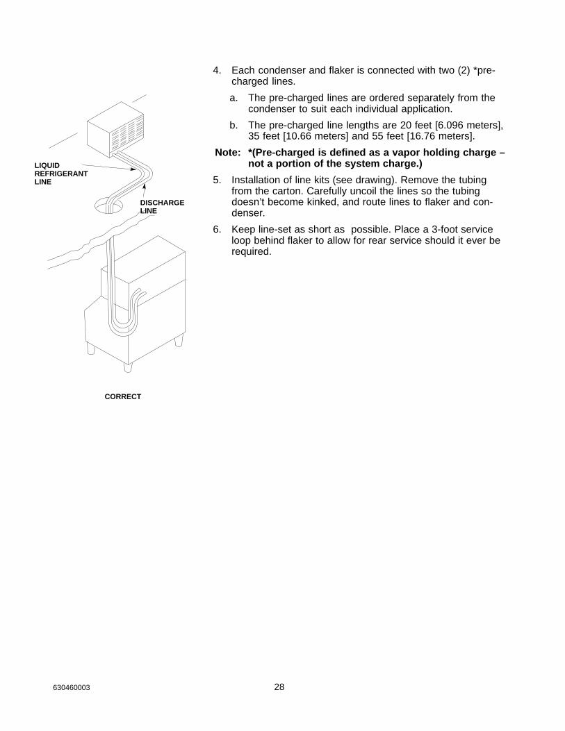
4. Each condenser and flaker is connected with two (2) *pre-charged lines.
a. The pre-charged lines are ordered separately from thecondenser to suit each individual application.
b. The pre-charged line lengths are 20 feet [6.096 meters],35 feet [10.66 meters] and 55 feet [16.76 meters].
Note: *(Pre-charged is defined as a vapor holding charge –not a portion of the system charge.)
5. Installation of line kits (see drawing). Remove the tubingfrom the carton. Carefully uncoil the lines so the tubingdoesn’t become kinked, and route lines to flaker and con-denser.
6. Keep line-set as short as possible. Place a 3-foot serviceloop behind flaker to allow for rear service should it ever berequired.
LIQUIDREFRIGERANTLINE
DISCHARGELINE
CORRECT
29 630460003
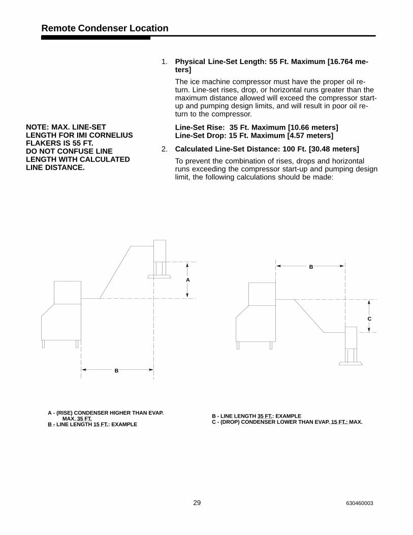
Remote Condenser Location
1. Physical Line-Set Length: 55 Ft. Maximum [16.764 me-ters]
The ice machine compressor must have the proper oil re-turn. Line-set rises, drop, or horizontal runs greater than themaximum distance allowed will exceed the compressor start-up and pumping design limits, and will result in poor oil re-turn to the compressor.
Line-Set Rise: 35 Ft. Maximum [10.66 meters]Line-Set Drop: 15 Ft. Maximum [4.57 meters]
2. Calculated Line-Set Distance: 100 Ft. [30.48 meters]
To prevent the combination of rises, drops and horizontalruns exceeding the compressor start-up and pumping designlimit, the following calculations should be made:
A - (RISE) CONDENSER HIGHER THAN EVAP. MAX. 35 FT.
B - LINE LENGTH 15 FT.: EXAMPLE
B - LINE LENGTH 35 FT.: EXAMPLEC - (DROP) CONDENSER LOWER THAN EVAP. 15 FT.: MAX.
A
B
B
C
NOTE: MAX. LINE-SETLENGTH FOR IMI CORNELIUSFLAKERS IS 55 FT. DO NOT CONFUSE LINELENGTH WITH CALCULATEDLINE DISTANCE.
30630460003
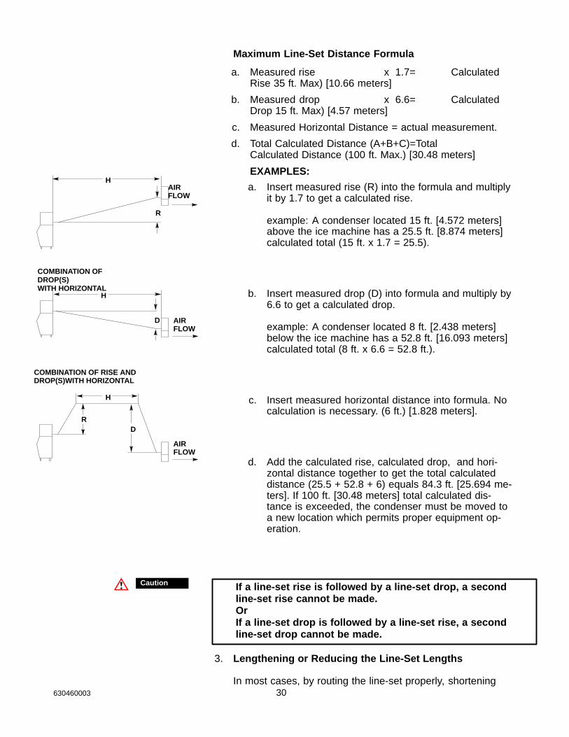
Maximum Line-Set Distance Formula
a. Measured rise x 1.7= CalculatedRise 35 ft. Max) [10.66 meters]
b. Measured drop x 6.6= CalculatedDrop 15 ft. Max) [4.57 meters]
c. Measured Horizontal Distance = actual measurement.
d. Total Calculated Distance (A+B+C)=Total Calculated Distance (100 ft. Max.) [30.48 meters]
EXAMPLES:
a. Insert measured rise (R) into the formula and multiplyit by 1.7 to get a calculated rise.
example: A condenser located 15 ft. [4.572 meters]above the ice machine has a 25.5 ft. [8.874 meters] calculated total (15 ft. x 1.7 = 25.5).
b. Insert measured drop (D) into formula and multiply by6.6 to get a calculated drop.
example: A condenser located 8 ft. [2.438 meters]below the ice machine has a 52.8 ft. [16.093 meters]calculated total (8 ft. x 6.6 = 52.8 ft.).
c. Insert measured horizontal distance into formula. Nocalculation is necessary. (6 ft.) [1.828 meters].
d. Add the calculated rise, calculated drop, and hori-zontal distance together to get the total calculateddistance (25.5 + 52.8 + 6) equals 84.3 ft. [25.694 me-ters]. If 100 ft. [30.48 meters] total calculated dis-tance is exceeded, the condenser must be moved toa new location which permits proper equipment op-eration.
Caution If a line-set rise is followed by a line-set drop, a secondline-set rise cannot be made. OrIf a line-set drop is followed by a line-set rise, a secondline-set drop cannot be made.
3. Lengthening or Reducing the Line-Set Lengths
In most cases, by routing the line-set properly, shortening
H
R
D
H
R
H
D
AIRFLOW
AIRFLOW
AIRFLOW
COMBINATION OFDROP(S)WITH HORIZONTAL
COMBINATION OF RISE ANDDROP(S)WITH HORIZONTAL
31 630460003
will not be necessary (refer to illustration). However, whenshortening or lengthening is required, do so before connect-ing the line-set to the ice machine or the remote condenser.This prevents the loss of refrigerant from the ice machine orthe condenser.
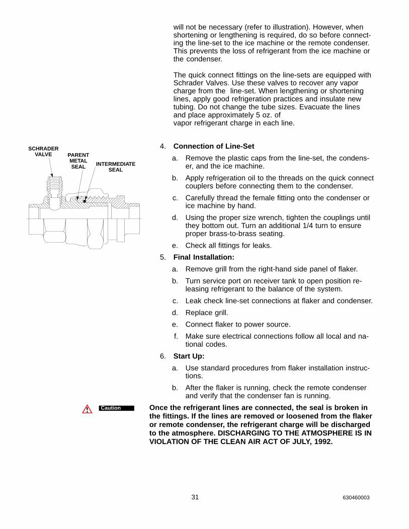
The quick connect fittings on the line-sets are equipped withSchrader Valves. Use these valves to recover any vaporcharge from the line-set. When lengthening or shorteninglines, apply good refrigeration practices and insulate newtubing. Do not change the tube sizes. Evacuate the linesand place approximately 5 oz. of vapor refrigerant charge in each line.
4. Connection of Line-Set
a. Remove the plastic caps from the line-set, the condens-er, and the ice machine.
b. Apply refrigeration oil to the threads on the quick connectcouplers before connecting them to the condenser.
c. Carefully thread the female fitting onto the condenser orice machine by hand.
d. Using the proper size wrench, tighten the couplings untilthey bottom out. Turn an additional 1/4 turn to ensureproper brass-to-brass seating.
e. Check all fittings for leaks.
5. Final Installation:
a. Remove grill from the right-hand side panel of flaker.
b. Turn service port on receiver tank to open position re-leasing refrigerant to the balance of the system.
c. Leak check line-set connections at flaker and condenser.
d. Replace grill.
e. Connect flaker to power source.
f. Make sure electrical connections follow all local and na-tional codes.
6. Start Up:
a. Use standard procedures from flaker installation instruc-tions.
b. After the flaker is running, check the remote condenserand verify that the condenser fan is running.
Once the refrigerant lines are connected, the seal is broken inthe fittings. If the lines are removed or loosened from the flakeror remote condenser, the refrigerant charge will be dischargedto the atmosphere. DISCHARGING TO THE ATMOSPHERE IS INVIOLATION OF THE CLEAN AIR ACT OF JULY, 1992.
INTERMEDIATESEAL
PARENTMETALSEAL
SCHRADERVALVE
Caution
32630460003
Head Pressure Control [Headmaster]
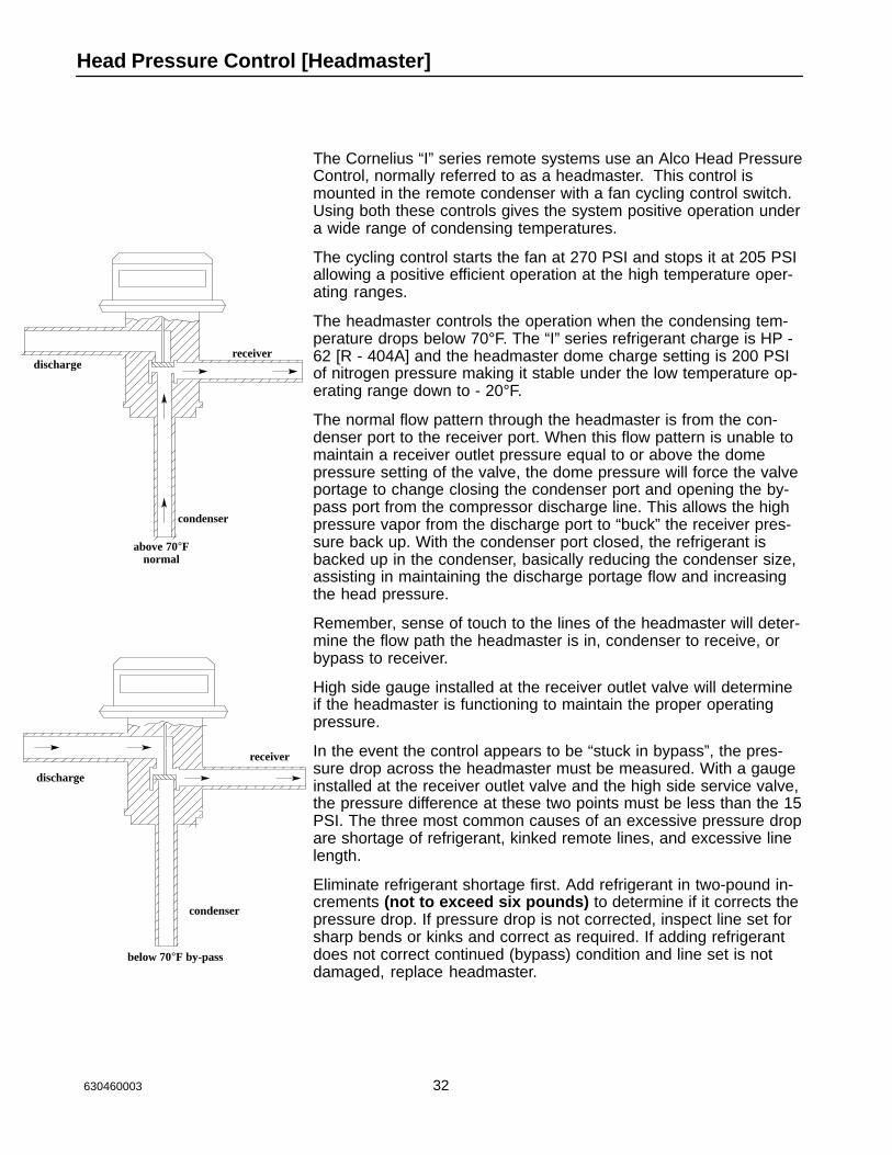
The Cornelius “I” series remote systems use an Alco Head PressureControl, normally referred to as a headmaster. This control ismounted in the remote condenser with a fan cycling control switch.Using both these controls gives the system positive operation undera wide range of condensing temperatures.
The cycling control starts the fan at 270 PSI and stops it at 205 PSIallowing a positive efficient operation at the high temperature oper-ating ranges.
The headmaster controls the operation when the condensing tem-perature drops below 70°F. The “I” series refrigerant charge is HP -62 [R - 404A] and the headmaster dome charge setting is 200 PSIof nitrogen pressure making it stable under the low temperature op-erating range down to - 20°F.
The normal flow pattern through the headmaster is from the con-denser port to the receiver port. When this flow pattern is unable tomaintain a receiver outlet pressure equal to or above the domepressure setting of the valve, the dome pressure will force the valveportage to change closing the condenser port and opening the by-pass port from the compressor discharge line. This allows the highpressure vapor from the discharge port to “buck” the receiver pres-sure back up. With the condenser port closed, the refrigerant isbacked up in the condenser, basically reducing the condenser size,assisting in maintaining the discharge portage flow and increasingthe head pressure.
Remember, sense of touch to the lines of the headmaster will deter-mine the flow path the headmaster is in, condenser to receive, orbypass to receiver.
High side gauge installed at the receiver outlet valve will determineif the headmaster is functioning to maintain the proper operatingpressure.
In the event the control appears to be “stuck in bypass”, the pres-sure drop across the headmaster must be measured. With a gaugeinstalled at the receiver outlet valve and the high side service valve,the pressure difference at these two points must be less than the 15PSI. The three most common causes of an excessive pressure dropare shortage of refrigerant, kinked remote lines, and excessive linelength.
Eliminate refrigerant shortage first. Add refrigerant in two-pound in-crements (not to exceed six pounds) to determine if it corrects thepressure drop. If pressure drop is not corrected, inspect line set forsharp bends or kinks and correct as required. If adding refrigerantdoes not correct continued (bypass) condition and line set is notdamaged, replace headmaster.
dischargereceiver
condenser
above 70°Fnormal
discharge
receiver
condenser
below 70°F by-pass
33 630460003
Remote System Evacuation/Re-charge
All field repairs to the sealed system must start with a total dis-charge of the system following the requirements of the Clean Air Actof July, 1992.
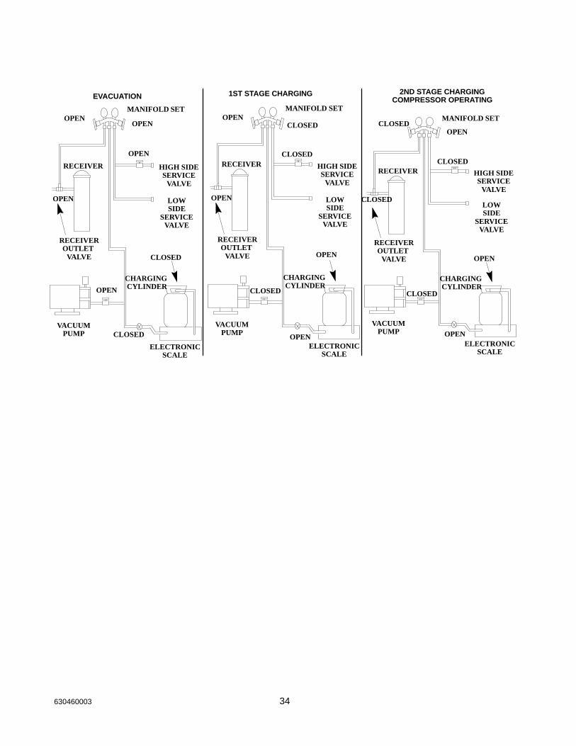
Proper evacuation of the total remote system will require a three (3)point hook-up of your manifold and hose set, (see drawing):
Point #1 - flaker receiver outlet valvePoint #2 - flaker high side service valvePoint #3 - flaker low side service valve
Evacuation:
1. With flaker power supply turned “OFF” disconnect and insu-late all 3 compressor leads at the compressor. Turn powersupply on, place power switch in the “on” position. This willenergize (open) the Liquid Line solenoid allowing evacuationof the Liquid Line between the solenoid and the expansionvalve(s).
2. Evacuate system to 200/250 microns or less. At this point,there should be a holding test of five(5) minutes. You mayexpect a slight loss of vacuum as normal. A rapid rise to nor-mal atmospheric pressure indicates moisture still present inthe system. On a “wet” system, it will prove beneficial to useheat lamps to warm the compressor dome and evaporatorsurface during evacuation.
3. Turn flaker power switch OFF. Reconnect compressor leads.
34630460003
EVACUATION
MANIFOLD SETOPEN
RECEIVER
OPEN
RECEIVEROUTLET
VALVE
OPEN
VACUUMPUMP
ELECTRONICSCALE
CHARGING CYLINDER
CLOSED
CLOSED
LOWSIDE
SERVICEVALVE
HIGH SIDESERVICE
VALVE
OPEN
OPEN
1ST STAGE CHARGING
MANIFOLD SETOPEN
RECEIVER
OPEN
RECEIVEROUTLET
VALVE
OPEN
VACUUMPUMP
ELECTRONICSCALE
CHARGING CYLINDER
CLOSED
LOWSIDE
SERVICEVALVE
HIGH SIDESERVICE
VALVE
2ND STAGE CHARGINGCOMPRESSOR OPERATING
MANIFOLD SET
RECEIVER
RECEIVEROUTLET
VALVE
OPENVACUUM
PUMP
ELECTRONICSCALE
CHARGING CYLINDER
CLOSED
CLOSED
LOWSIDE
SERVICEVALVE
HIGH SIDESERVICE
VALVE
OPEN
OPEN
CLOSED
CLOSED
OPEN
CLOSED
CLOSED
35 630460003
4. *After proper evacuation hold test has been performed, therefrigerant charge should be “dumped” into the receiver untilthe pressure equalizes, stopping the flow. Do not try tothrottle the refrigerant flow. Doing so will allow systempressure to balance too soon. The high-side service valveshould be closed and the balance of the charge fed slowlythrough the suction side service valve with the compressoroperational. Control the feed rate at no faster than four (4)ounces [113.g] per minute to ensure the compressor oil doesnot become too saturated with refrigerant resulting in a lossof compressor lubrication.
5. All refrigerant re-charging must be weighed into the system,utilizing an electronic charging scale. DO NOT attempt torecharge the system by sight glass, system pressure, amper-age, frost line or sweat patterns.
6. Always leak check entire system after recharge.
Before programming the electronic scales to “dump” thecharge, de-energize the liquid line solenoid, close the shut-off valve onvacuum pump and low side of the manifold set.
Caution
36630460003
ÄÄÄÄÄÄ
WATERDUMP VALVE
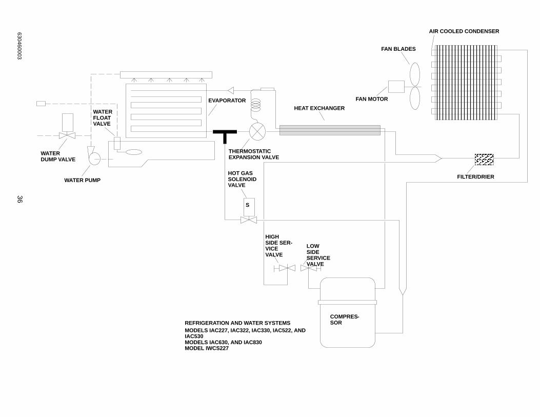
REFRIGERATION AND WATER SYSTEMSMODELS IAC227, IAC322, IAC330, IAC522, ANDIAC530MODELS IAC630, AND IAC830MODEL IWCS227
WATERFLOATVALVE
WATER PUMP
EVAPORATOR
THERMOSTATIC EXPANSION VALVE
HOT GASSOLENOIDVALVE
S
HEAT EXCHANGER
HIGHSIDE SER-VICEVALVE
LOWSIDESERVICEVALVE
COMPRES-SOR
AIR COOLED CONDENSER
FAN BLADES
FAN MOTOR
FILTER/DRIER
37630460003
ÄÄÄÄÄÄ
AIR COOLED CONDENSER
WATERDUMP VALVE
WATER PUMP WATERFLOAT VALVE
EVAPORATORTHERMOSTATICEXPANSIONVALVE
HOT GASSOLENOID VALVE
EVAPORATOR
THERMOSTATICEXPANSIONVALVE
HEAT EXCHANGER
HIGH SIDESERVICEVALVE
LOW SIDESERVICEVALVE
COMPRES-SOR
FILTER/DRIER
FAN MOTOR
FAN BLADES
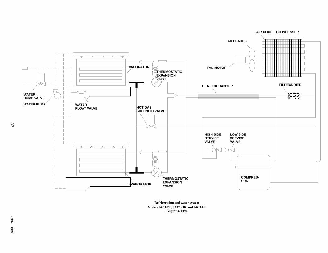
Refrigeration and water systemModels IAC1030, IAC1230, and IAC1448
August 3, 1994
38630460003
WATER-COOLED CONDENSER
ÄÄÄÄ
WATER REGULATINGVALVE
WATER INLET
FILTER/DRIERPRESSURE SWITCH
COMPRESSOR
HIGH SIDESERVICEVALVE
LOW SIDESERVICEVALVE
HEAT EXCHANGEREVAPORATOR
THERMOSTATICEXPANSION VALVE
HOT GASSOLENOIDVALVE
WATERFLOATVALVE
WATERDUMP VALVE
WATER PUMP
S
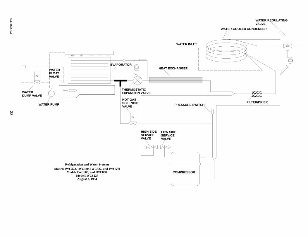
Refrigeration and Water SystemsModels IWC322, IWC330, IWC522, and IWC530
Models IWC603, and IWC830 Model IWCS227August 3, 1994
S
39630460003
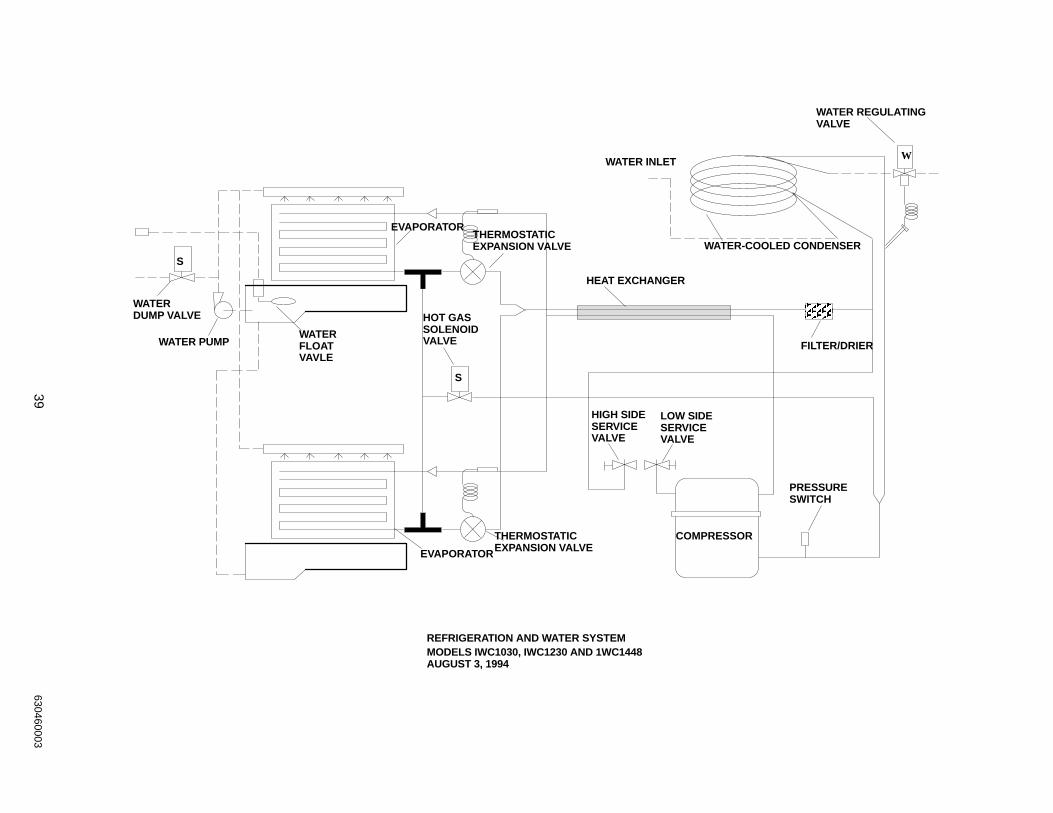
ÄÄÄÄ
WATERDUMP VALVE
WATER PUMPWATERFLOATVAVLE
EVAPORATOR
EVAPORATOR
HOT GASSOLENOIDVALVE
S
THERMOSTATICEXPANSION VALVE
THERMOSTATICEXPANSION VALVE
HEAT EXCHANGER
WATER INLET
WATER-COOLED CONDENSER
WATER REGULATINGVALVE
FILTER/DRIER
HIGH SIDESERVICEVALVE
LOW SIDESERVICEVALVE
PRESSURE SWITCH
COMPRESSOR
S
W
REFRIGERATION AND WATER SYSTEMMODELS IWC1030, IWC1230 AND 1WC1448AUGUST 3, 1994
40630460003
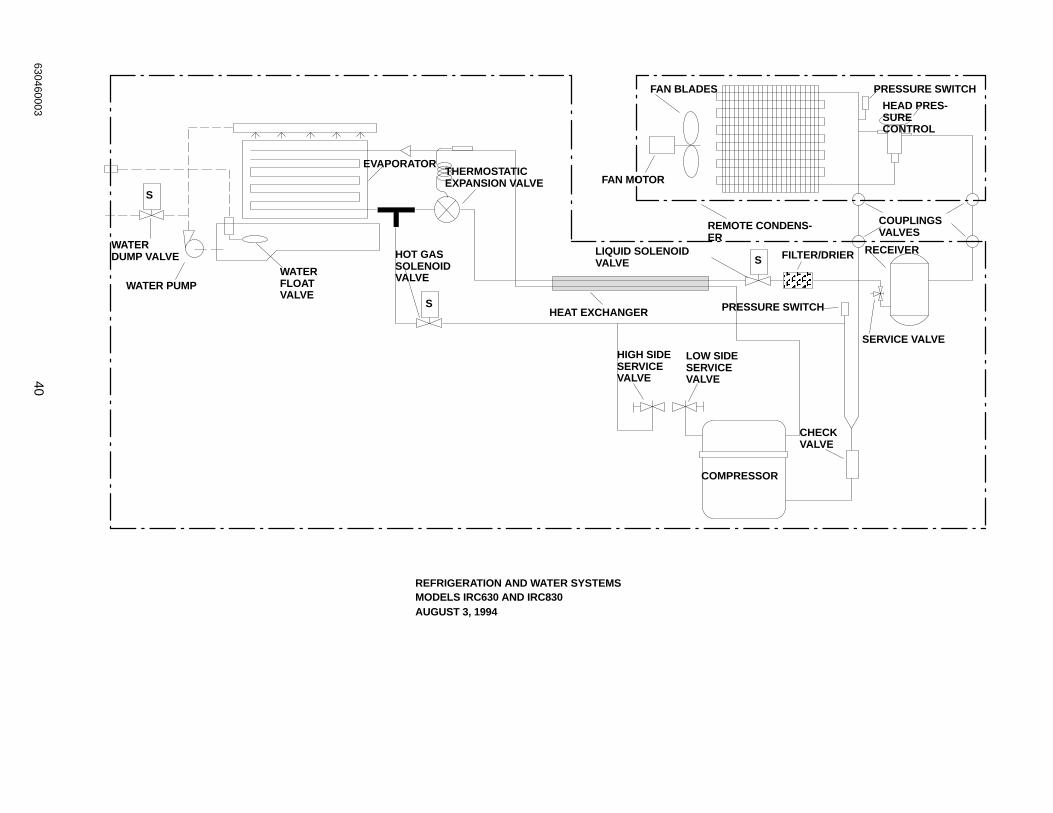
ÄÄÄÄ
WATERDUMP VALVE
WATER PUMPWATERFLOATVALVE
EVAPORATOR
HOT GASSOLENOIDVALVE
S
THERMOSTATICEXPANSION VALVE
S
HEAT EXCHANGER
HIGH SIDESERVICEVALVE
LOW SIDESERVICEVALVE
COMPRESSOR
S FILTER/DRIER
PRESSURE SWITCH
LIQUID SOLENOIDVALVE
REMOTE CONDENS-ER
FAN MOTOR
FAN BLADES PRESSURE SWITCH
HEAD PRES-SURECONTROL
COUPLINGSVALVES
RECEIVER
SERVICE VALVE
CHECKVALVE
REFRIGERATION AND WATER SYSTEMSMODELS IRC630 AND IRC830AUGUST 3, 1994
41630460003
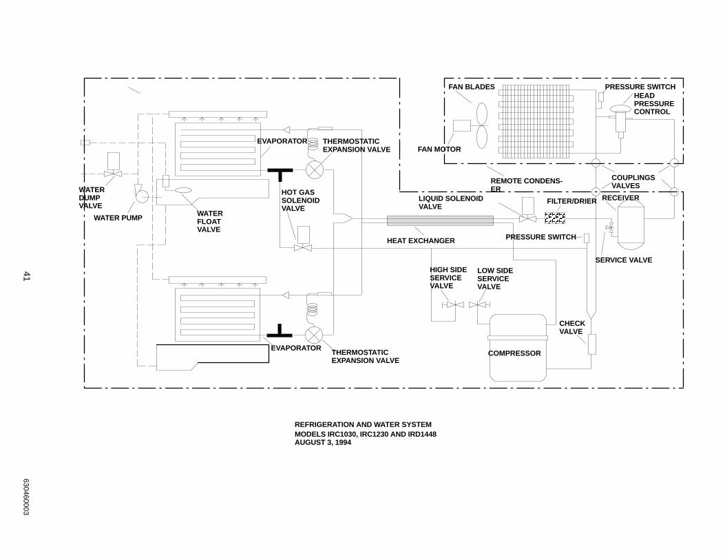
ÄÄÄ
WATERDUMP VALVE
WATER PUMPWATERFLOATVALVE
EVAPORATOR
HOT GASSOLENOIDVALVE
THERMOSTATICEXPANSION VALVE
REMOTE CONDENS-ER
FAN MOTOR
FAN BLADES PRESSURE SWITCHHEADPRESSURECONTROL
HEAT EXCHANGER
HIGH SIDESERVICEVALVE
LOW SIDESERVICEVALVE
COMPRESSOR
FILTER/DRIER
PRESSURE SWITCH
LIQUID SOLENOIDVALVE
CHECKVALVE
SERVICE VALVE
COUPLINGSVALVES
RECEIVER
EVAPORATORTHERMOSTATICEXPANSION VALVE
REFRIGERATION AND WATER SYSTEMMODELS IRC1030, IRC1230 AND IRD1448AUGUST 3, 1994
42630460003
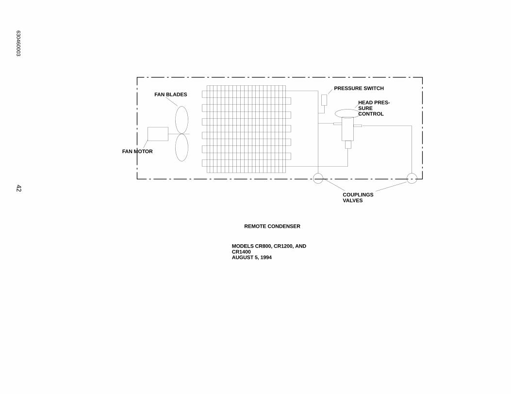
FAN MOTOR
FAN BLADESPRESSURE SWITCH
HEAD PRES-SURECONTROL
COUPLINGSVALVES
REMOTE CONDENSER
MODELS CR800, CR1200, ANDCR1400AUGUST 5, 1994
One Cornelius PlaceAnoka, Minnesota 55303-6234
(612) 421-6120(800) 238-3600
Corporate Headquarters:
IMI CORNELIUS INC.
Related Documents