The Heavy Ion Fusion Science Virtual National Laboratory 1 Peter Seidl Lawrence Berkeley National Laboratory and the Heavy Ion Fusion Science Virtual National Laboratory Progress in neutralized beam compression and focusing Outline 1. Neutralized drift compression 2. Pulse Line Ion Accelerator 3. Solenoid transport VNL-PAC LLNL August 9, 2006

The Heavy Ion Fusion Science Virtual National Laboratory 1 Peter Seidl Lawrence Berkeley National Laboratory and the Heavy Ion Fusion Science Virtual National.
Dec 17, 2015
Welcome message from author
This document is posted to help you gain knowledge. Please leave a comment to let me know what you think about it! Share it to your friends and learn new things together.
Transcript

The Heavy Ion Fusion Science Virtual National Laboratory 1
Peter Seidl Lawrence Berkeley National Laboratoryand the Heavy Ion Fusion Science Virtual National Laboratory
Progress in neutralized beam compression and focusing
Outline1. Neutralized drift compression2. Pulse Line Ion Accelerator3. Solenoid transport
VNL-PAC
LLNL
August 9, 2006

The Heavy Ion Fusion Science Virtual National Laboratory 2
Collaborators -
J. Armijo,a,g D. Baca, a F.M. Bieniosek, a J. Coleman, a,f R. C. Davidson, d
P.C. Efthimion, d A. Friedman, b E.P. Gilson, d D. Grote, b I. Haber, c
E. Henestroza, a I. Kaganovich, d M. Kireeff-Covo, b,f M. Leitner, a
B.G. Logan, a A.W. Molvik, b P.A. Seidl,a D.V. Rose, e P.K. Roy, a
A.B. Sefkow a W.M. Sharp, b J.L. Vay, a W.L. Waldron, a D.R. Welch e
and S.S. Yu a aLawrence Berkeley National Laboratory, Berkeley, CA 94720, U.S.A.
bLawrence Livermore National Laboratory, Livermore, CA 94550, U.S.A.cUniversity of Maryland, College Park, MD 20742-3511 CA, U.S.A.
dPrinceton Plasma Physics Laboratory, Princeton, NJ 08543-0451, U.S.A.eVoss Scientific, Albuquerque, NM 87108, U.S.A.
fUniversity of California, Berkeley, CA 94720, U.S.A.gUniversite ENS, Paris, France.

The Heavy Ion Fusion Science Virtual National Laboratory 3
Neutralized drift compression
Acceleration and velocity ramp for compression induction core(s) or other (Pulse Line Ion Accelerator?)
Need to cancel out space charge plasma column with np >> nb
Preservation of emittance
The Heavy Ion Fusion Science Virtual National Laboratory 4
Huge advantage of neutralized compression for high perveance (K ≈ 10-3)
Beam density
3x1012 cm-3 plasma
vacuum3x1012 cm-3 plasma
vacuum
vacuum
3x1012 cm-3 plasma
Beam Conditions at Focus
~500 x enhancement of intensity on target is possible
E = 300 keV, K+
I = 44 mA
Solenoids
B1=2.445 T
B2 = 2.6 T
Bunching core
200 kV, 200 ns

The Heavy Ion Fusion Science Virtual National Laboratory 5
Before WDM user facility, we plan a modest upgrade … NDCX-2
Solenoid matching
Alternative:2.8 MeV Li+ -- Possibly less costly.
Issues: source, beam formation, higher beam at injection, Tll

The Heavy Ion Fusion Science Virtual National Laboratory 6
1. Neutralized drift compression experiments
2006 Goal: Experiments and modeling on combined transverse and longitudinal focusing of intense heavy-ion beams.
injected 10-sec, K+, 280-310 keV, 22-26 mA,
bunch a portion of beam with induction module head to tail velocity ramp, v/v ≈ 15% (≈0.2 s)
Plasma column neutralizes space charge
€
€
t =L
v2
2kTL
M
If TL limits compression, bunch duration:
L = drift lengthv = <velocity>

The Heavy Ion Fusion Science Virtual National Laboratory 7
plasma sources for 1-2 meter drift compression.
Filter cathode arc plasma sourceInjection from end into weak solenoid
ne ≈ 5 x 1011 cm-3 measured
barium titanate ceramic ring.
Ferro-electric plasma sourceGenerated from cylindrical surface
ne ≈ 2-8 x 1010 cm-3
Beam test planned this summer(Efthimion, Gilson, et al.)
Both approaches not yet optimized, higher density possible.
BEAM

The Heavy Ion Fusion Science Virtual National Laboratory 8
Neutralized drift compression experiment (NDCX)
Induction bunchingmodule:
-80 < V < +70 kV applied to the beam
Building one more module with greater V
BUNCHING MODULE

The Heavy Ion Fusion Science Virtual National Laboratory 9
Experiment for neutralized drift compression
injector
quadrupoles --> solenoids
Support rails
Drift compression / plasma
Induction bunching
D
D, Plasmasource
En
ergy An
alyzer
The Heavy Ion Fusion Science Virtual National Laboratory 10
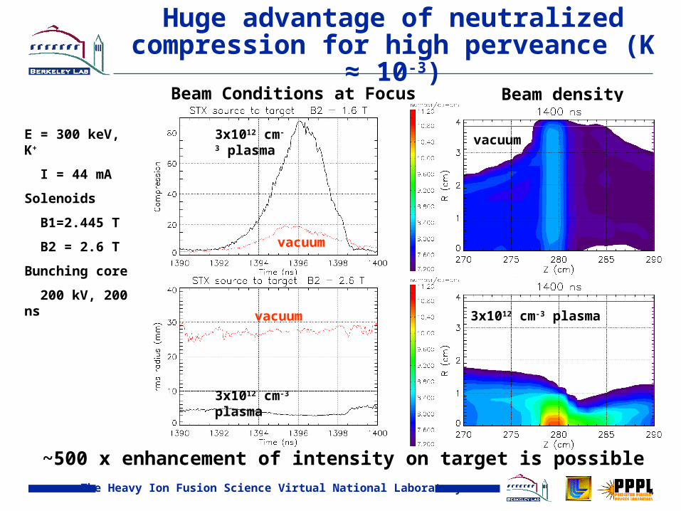
60x beam compression observed in a 1-meter neutralized drift experiment agreed with EM-PIC model results.
LSP*: EM - PIC code including plasma modeling and beam plasma interaction.*Voss Scientific, www.vosssci.com
4.5 ns FWHM
np ≈ 5 x 1010 cm-3
Average of 4 pulses, with detailed waveform input to modeling…
Toward target heating experiments: Will characterize shot-to-shot reproducibility / reliablility.
The Heavy Ion Fusion Science Virtual National Laboratory 11
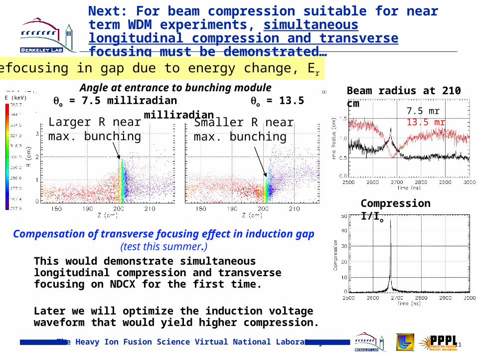
Next: For beam compression suitable for near term WDM experiments, simultaneous longitudinal compression and transverse focusing must be demonstrated…
This would demonstrate simultaneous longitudinal compression and transverse focusing on NDCX for the first time.
Later we will optimize the induction voltage waveform that would yield higher compression.
Angle at entrance to bunching module o = 7.5 milliradian o = 13.5 milliradian
Larger R near max. bunching
Smaller R near max. bunching
Beam radius at 210 cm
Compression I/Io
7.5 mr 13.5 mr
E (keV)
Compensation of transverse focusing effect in induction gap (test this summer.)
Net defocusing in gap due to energy change, Er
The Heavy Ion Fusion Science Virtual National Laboratory 12
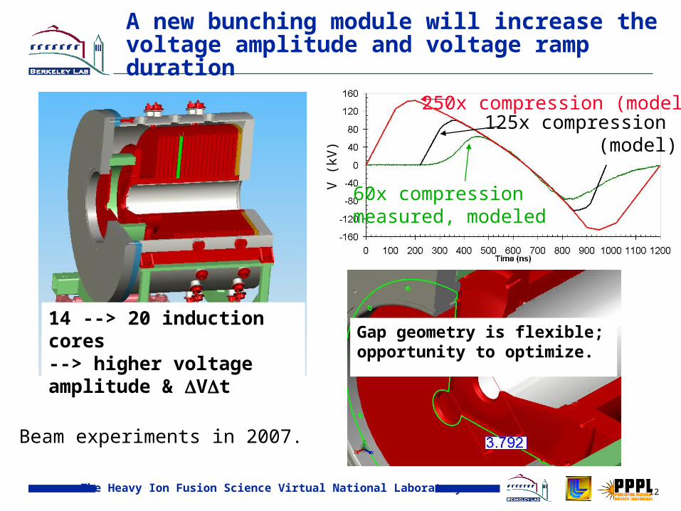
A new bunching module will increase the voltage amplitude and voltage ramp duration
14 --> 20 induction cores --> higher voltage amplitude & Vt
Gap geometry is flexible; opportunity to optimize.
V (
kV)
250x compression (model)
60x compression measured, modeled
125x compression (model)
Beam experiments in 2007.

The Heavy Ion Fusion Science Virtual National Laboratory 13
Gap geometry - design allows for straightforward modifications
Removeable plates insulator
Plasma & drift compression
Induction cores
acceleration gap

The Heavy Ion Fusion Science Virtual National Laboratory 14
A final focus solenoid is needed to achieve Ttgt~1 eV. Modeling for NDCX and HCX input beams
Plasma neutralization z>-15 cm
XXTilt gap
100 ns300 ns 500 ns 700 ns
870 ns
HCX, 1.6 MeV, Io = 0.36 ANDCX, 0.4 MeV, Io = 0.07 AB(Gauss)
100
1.5x10⁴
Log(ni)
7.00
13.00
25 cm solenoid
Compressed beam
Preheat?
Preheat?
Simulations: D. Welch (Voss Sci.) & A. Sefkow (PPPL)
The Heavy Ion Fusion Science Virtual National Laboratory 15
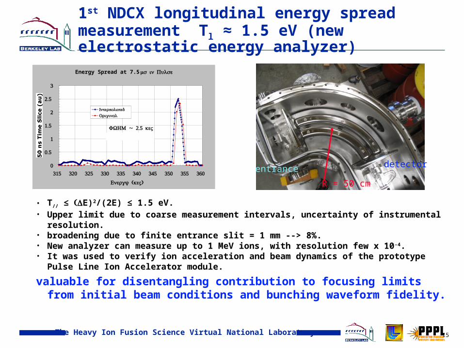
1st NDCX longitudinal energy spread measurement Tl ≈ 1.5 eV (new electrostatic energy analyzer)
• T// ≤ E)2/(2E) ≤ 1.5 eV. • Upper limit due to coarse measurement intervals, uncertainty of instrumental resolution. • broadening due to finite entrance slit = 1 mm --> 8%. • New analyzer can measure up to 1 MeV ions, with resolution few x 10-4.• It was used to verify ion acceleration and beam dynamics of the prototype Pulse Line Ion
Accelerator module.
valuable for disentangling contribution to focusing limits from initial beam conditions and bunching waveform fidelity.
Energy Spread at 7.5 s in Pulse
0
0.5
1
1.5
2
2.5
3
315 320 325 330 335 340 345 350 355 360
( )Energy keV
50 ( )ns Time Slice au
InterpolatedOriginal
~ 2.5 FWHM keVTL = 1.589 eV
Photo of analyzer
R = 50 cm
entrance detector

The Heavy Ion Fusion Science Virtual National Laboratory 16
2 . Initial experiments with a Pulse Line Ion Accelerator (PLIA) accelerator section. Potential for inexpensive, high-gradient ion acceleration
transformer coupling (5:1 step-up)
1.2 m
Moving bucket
helical coil structure, submerged in a di-electric medium (oil) powered by a pulsed, HV waveform --> energy gains many times higher than the input voltage to the helix.
Beam energy modulation of -80 keV to +150 keV was measured using a PLIA input voltage waveform of -21 kV to +12 kV.
Comparison to simulations, dynamics understood. Flashover presently limits <E> ≈ 150 kV /m -- see Coleman et al. poster
The Heavy Ion Fusion Science Virtual National Laboratory 17
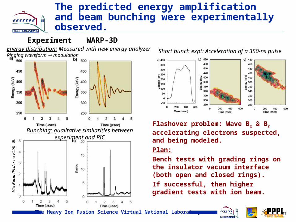
The predicted energy amplification and beam bunching were experimentally observed.
Experiment WARP-3DEnergy distribution: Measured with new energy analyzerRinging waveform modulation
I/Io
Rat
io (
PLI
A /
no P
LIA
)
Bunching: qualitative similarities between experiment and PIC
Short bunch expt: Acceleration of a 350-ns pulse
Flashover problem: Wave Bz & Br accelerating electrons suspected, and being modeled.
Plan:
Bench tests with grading rings on the insulator vacuum interface (both open and closed rings).
If successful, then higher gradient tests with ion beam.
The Heavy Ion Fusion Science Virtual National Laboratory 18
3. Studying solenoid transport of high perveance beams for future WDM experiments
Solenoids can transport high current, space charge (in
one beam). Objectives: •match and transport a space-charge-dominated ion beam, maintain low emittance (Brillouin flow).•study associated electron-cloud and gas effects that may limit
the beam quality or beam control in a longer transport system. •Beam halo scraping e- emission•Ionization of background gas•Expelled ions hitting vacuum wall•Ionization of desorbed gas
Compare / contrast with experience in magnetic quadrupoles. See A. Molvik talk.

The Heavy Ion Fusion Science Virtual National Laboratory 19
Begun experiment by diagnosing beam before and after 2 solenoids. Later will extend to 4 solenoids.
Using pulsed solenoids, B ≤ 3 Tesla, t = 4 ms. Measured & modeled eddy current effects at beginning and end of beamline (e).
(e)
(e)S1 S2
Same injector as NTX/NDCX
E = 300 keVI = 25-45 mABS1 = BS2 = 2.7 T
Diagnostics for transverse phase
space:Slits, slit-collectors, scintillator / gated CCD camera
The Heavy Ion Fusion Science Virtual National Laboratory 20
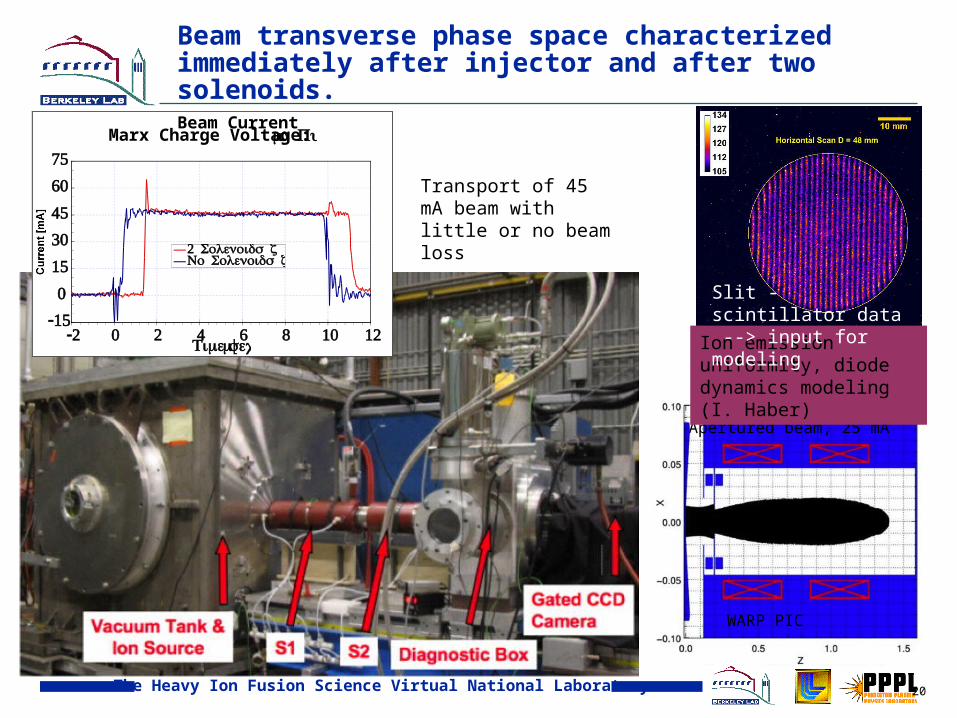
Beam transverse phase space characterized immediately after injector and after two solenoids.
Beam Current Marx Charge Voltage: 300 kV 10 s Pulse
-15
0
15
30
45
60
75
-2 0 2 4 6 8 10 12 [Time ]sec
[ ]Current mA2 = 156 Solenoids z cm
= 41 No Solenoids z cm
Apertured beam, 25 mA
WARP PIC
Transport of 45 mA beam with little or no beam loss
Ion emission uniformity, diode dynamics modeling (I. Haber)
Slit - scintillator data --> input for modeling

The Heavy Ion Fusion Science Virtual National Laboratory 21
Negatively biased e- or “traps” control electrons from aperture and intercepting diagnostics
electrons are liberated wherever beam ions hit surfaces
aperture plates and diagnostics, such as slit-plates, are major sources
rings at -3 kV on both sides of an aperture keep electrons out of diode
third ring is placed after the solenoids to block electrons from diagnostics

The Heavy Ion Fusion Science Virtual National Laboratory 22
At first, x-x’ phase space showed spurious time dependence due to e-trap, diagnostics in Bsol
Injected: = 23 mm•mradAfter two solenoids = 35 mm•mrad ~ 2x i
WARP PIC envelope agrees near beam head.
But, large envelope parameter variation within ~2 s. Electron/gas effects? Diagnostics in ~1 kG fringe field?
WARP e-cloud modeling (W.Sharp)
Capacitive signal
€
∝∂I∂t
ionized H2 migrating to trap
Oscillations as in a virtual cathode

The Heavy Ion Fusion Science Virtual National Laboratory 23
Moved the diagnostics downstream 30 cm, Bz = 3 kG --> 0.1 kG.
Camera
low emittance, small envelope time dependence.
Full Beam Envelope Parameters at Vertical Slit Plane vs Time
8
9
10
11
12
2.5 5 7.5 10Time ( )s
( )b mm
0
4
8
12
16
( )b' mrad
( )b mm ( )b' mrad
= 20 mm•mrad
End diagnostic
box
End diagnostic
box
K+source

The Heavy Ion Fusion Science Virtual National Laboratory 24
4-Solenoid Transport eXperiment, e- cloud diagnostics, and neutralized drift compression tune
Camera
•Faraday cup•4” square Scintillator•Horizontally & Vertically Driven Slits and Slit-Cups
254.31 cm
End diagnostic
box
2.6 T 1.4 T 1.4 T 2.3 T
Ib = 26 mA (aperture)

The Heavy Ion Fusion Science Virtual National Laboratory 25
First measurements through four solenoids, 26 mA beam (aperture)
Issues: centroid / alignmentni = 0.06 mm mrad nf = 0.08 mm-mrad

The Heavy Ion Fusion Science Virtual National Laboratory 26
Addition of two more solenoids e-cloud studies, matching into NDC
Marx column
Ion source
solenoids
diagnostics
The Heavy Ion Fusion Science Virtual National Laboratory 27
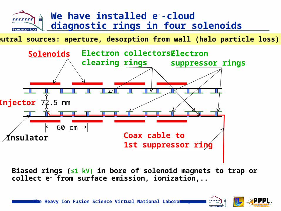
We have installed e--cloud diagnostic rings in four solenoids
Solenoids Electron collectors/ clearing rings
Electron suppressor rings
Coax cable to 1st suppressor ring
Injector 72.5 mm
60 cm
Insulator
Biased rings (≤1 kV) in bore of solenoid magnets to trap or collect e- from surface emission, ionization,..
e-, neutral sources: aperture, desorption from wall (halo particle loss).

The Heavy Ion Fusion Science Virtual National Laboratory 28
Rings in solenoids short enough that Ez > 0 to expel (or trap) electrons
• Negative electrode in solenoid will expel e-.
• Can expel electrons in outer 0.1-0.5 of beam radius.
• Positive electrode between will suppress emission.
• Reverse bias to emit and trap e-.
Solenoids

The Heavy Ion Fusion Science Virtual National Laboratory 29
STX e-cloud diagnostics
The Heavy Ion Fusion Science Virtual National Laboratory 30
1
2
7
6
5
4
3
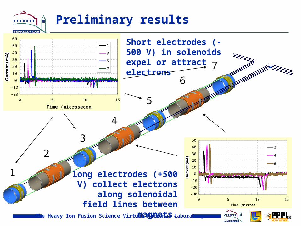
Preliminary results
Short electrodes (-500 V) in solenoids expel or attract electrons
-30
-20
-10
0
10
20
30
40
50
0 5 10 15
Time (microsec)
Current (mA)
2
4
6
-20
-10
0
10
20
30
40
50
60
0 5 10 15
Time (microsecond)
Current (mA)
1
3
5
7
long electrodes (+500 V) collect electrons along
solenoidal field lines between magnets.

The Heavy Ion Fusion Science Virtual National Laboratory 31
E. H.
New diagnostic to measure Larmor rotation of beam within the solenoid
Pinhole array followed by scintillator (z ≈ 10 cm). Viewing geometry (for CCD camera). For Larmor = 1.7 x 10⁶ rad / sec, rbeam ≈ 2.5 cm, = 142 mrad.
Image on scintillator10 cm downstream. Pinhole array
3-4 mm
rev/
sec

The Heavy Ion Fusion Science Virtual National Laboratory 32
Implementation in the experiment
10 cm
Viewing port for image intensified CCD camera
Issues: gas desorption, ionization
Control of secondary ions, e-

The Heavy Ion Fusion Science Virtual National Laboratory 33
conclusion and summary
1. Neutralized drift compression:a) Will attempt simultaneous longitudinal beam compression with
transverse compression this summer. b) Tl ≈ 1 eV: inferred from compressed pulse width & also consistent with
uncompressed beam through new energy analyzer. More measurements planned, valuable for disentangling contribution to focusing limits from initial beam conditions and bunching waveform fidelity.
c) A new induction bunching module may provide compression up to 200x.
d) 5-15 Tesla final focus solenoid is planned to increase transverse compression to < 1 mm.
2. Pulse Line Ion Accelerator:a) Experimental verification of the predicted PLIA beam dynamics: beam
energy gains many times higher than the input voltageb) Flashover problem being pursued with design modifications,
modeling…3. Solenoid transport
a) Injected and matching high-perveance beam into solenoid channel. Beam dynamics studies, gas and electron effects…

The Heavy Ion Fusion Science Virtual National Laboratory 34
Extra slides…

The Heavy Ion Fusion Science Virtual National Laboratory 35
60x beam compression observed in a 1-meter neutralized drift experiment agreed with EM-PIC model results.
LSP*: EM - PIC code including plasma modeling and beam plasma interaction.
*Voss Scientific, www.vosssci.com
4.5 ns FWHM
05
101520253035404550
3.92 3.94 3.96 3.98 4Time (uS)
Exp. plasma on
Exp. plasma offLSP plasma off
LSP plasma on
np ≈ 5 x 1010 cm-3
Early comparisons,Effect of plasma…
Average of 4 pulses, with detailed waveform input to modeling…

The Heavy Ion Fusion Science Virtual National Laboratory 36
0
5
10
15
20
25
30
35
40
3.6 3.65 3.7 3.75 3.8
280 keV
290 keV300 keV
310keV
Next: For beam compression suitable for near term WDM experiments, simultaneous longitudinal compression and transverse focusing must be demonstrated…
0 50 100 150 200Time ( sec)
0 50 100 150 200Time ( sec)
Experiment
Theory (LSP)
Bea
m c
omp
ress
ion
I/I o
Snapshot at fixed location. Induction module voltage, entrance envelope held constant

The Heavy Ion Fusion Science Virtual National Laboratory 37
E-Cloud diagnostic objectives in solenoids
• Minimize electrons – suppressors (traps) biased negatively (≤1 kV) to expel
electrons (≥23 ns ne/nb ~ 0.01%) and collectors (clearing rings) biased positively
(≤1 kV) to collect them and suppress emission.
• Suppressor electrodes short enough that potential peaks at center with axial E-field
throughout to repel e- (length ~ diameter)
• Bias potential of ≤1 kV is 2-4x beam potential – adequate?
• Can expel electrons in outer 0.1-0.5 of beam radius.
• Tilting bias (50 V/solenoid) expels some (to most) e- at all radii in ~1 µs.
Or
• Maximize electrons in Penning Trap geometry – “suppressors” (+) to confine
electrons within solenoid and “collectors” (-) to emit e-.• Ionization of gas: ne/nb ~ 10% for 20 µs pulse at 10-5 torr, assume 10-16 cm2. Desorbed
gas moves a few cm, some will reach axis. May be able to photograph from diag. tank (at end).
• Wall emission from negative “collectors”: ne/nb ~ 14% for 10 µA loss (high?), 900 µA
emission. Collect on positive “suppressors” when B-field turns off?
Related Documents