INTERNATIONAL JOURNAL FOR NUMERICAL METHODS IN FLUIDS Int. J. Numer. Meth. Fluids 2002; 40:323–332 (DOI: 10.1002/d.289) The harmonic adjoint approach to unsteady turbomachinery design M. C. Duta ∗; † , M. B. Giles ‡ and M. S. Campobasso § University of Oxford; Computing Laboratory; Oxford OX1 3QD; U.K. SUMMARY In recent years, there has been rapid progress in aerodynamic optimization methods which use adjoint ow analysis to eciently calculate the sensitivity of steady-state objective functions to changes in the underlying design variables. This paper shows that the same adjoint approach can be used in turbomachinery applications in which the primary concern is blade vibration due to harmonic ow unsteadiness. The paper introduces the key engineering concepts and discusses the derivation of the adjoint analysis at the algebraic level. The emphasis is on the algorithmic aspects of the analysis, on the iterative solution method and on the role played by the strong solid wall boundary condition, in particular. The novel ideas are exploited to reveal the potential of the approach in the minimization of the unsteady vibration of turbomachinery blades due to incident wakes. Copyright ? 2002 John Wiley & Sons, Ltd. KEY WORDS: computational uid dynamics; adjoint method; aeroelastic optimization; vibration minimization 1. INTRODUCTION Modern turbomachinery has to meet exacting standards of eciency resulting in low weight and highly loaded engine components. As a consequence, high cycle fatigue due to me- chanical vibration caused by unsteady aerodynamic forces has become an important concern to be addressed at an early stage of the engine design cycle. Over the past two decades, a number of aeroelasticity methods have emerged to address this need varying from uncoupled ∗ Correspondence to: M. C. Duta, Computing Laboratory, University of Oxford, Wolfson Building, Parks Road, Oxford OX1 3QD, U.K. † E-mail: [email protected] ‡ E-mail: [email protected] § E-mail: [email protected] Contract=grant sponsor: Engineering and Physical Sciences Research Council; contract=grant number: GR=L95700 Contract=grant sponsor: Rolls-Royce plc Contract=grant sponsor: DERA Contract=grant sponsor: BAESystems plc Received May 2001 Copyright ? 2002 John Wiley & Sons, Ltd. Revised October 2001

Welcome message from author
This document is posted to help you gain knowledge. Please leave a comment to let me know what you think about it! Share it to your friends and learn new things together.
Transcript
INTERNATIONAL JOURNAL FOR NUMERICAL METHODS IN FLUIDSInt. J. Numer. Meth. Fluids 2002; 40:323–332 (DOI: 10.1002/�d.289)
The harmonic adjoint approach to unsteadyturbomachinery design
M. C. Duta∗;†, M. B. Giles‡ and M. S. Campobasso§
University of Oxford; Computing Laboratory; Oxford OX1 3QD; U.K.
SUMMARY
In recent years, there has been rapid progress in aerodynamic optimization methods which use adjoint�ow analysis to e�ciently calculate the sensitivity of steady-state objective functions to changes inthe underlying design variables. This paper shows that the same adjoint approach can be used inturbomachinery applications in which the primary concern is blade vibration due to harmonic �owunsteadiness.The paper introduces the key engineering concepts and discusses the derivation of the adjoint analysis
at the algebraic level. The emphasis is on the algorithmic aspects of the analysis, on the iterative solutionmethod and on the role played by the strong solid wall boundary condition, in particular. The novelideas are exploited to reveal the potential of the approach in the minimization of the unsteady vibrationof turbomachinery blades due to incident wakes. Copyright ? 2002 John Wiley & Sons, Ltd.
KEY WORDS: computational �uid dynamics; adjoint method; aeroelastic optimization; vibrationminimization
1. INTRODUCTION
Modern turbomachinery has to meet exacting standards of e�ciency resulting in low weightand highly loaded engine components. As a consequence, high cycle fatigue due to me-chanical vibration caused by unsteady aerodynamic forces has become an important concernto be addressed at an early stage of the engine design cycle. Over the past two decades, anumber of aeroelasticity methods have emerged to address this need varying from uncoupled
∗ Correspondence to: M. C. Duta, Computing Laboratory, University of Oxford, Wolfson Building, Parks Road,Oxford OX1 3QD, U.K.
† E-mail: [email protected]‡ E-mail: [email protected]§ E-mail: [email protected]
Contract=grant sponsor: Engineering and Physical Sciences Research Council; contract=grant number: GR=L95700Contract=grant sponsor: Rolls-Royce plcContract=grant sponsor: DERAContract=grant sponsor: BAESystems plc
Received May 2001Copyright ? 2002 John Wiley & Sons, Ltd. Revised October 2001
324 M. C. DUTA, M. B. GILES AND M. S. CAMPOBASSO
linearized potential �ow solvers [1, 2] to fully coupled non-linear three-dimensional unsteadyviscous methods [3]. Within this range, the uncoupled linear harmonic Euler and Navier–Stokes methods have proved to be a successful compromise between accuracy and cost andare now widely preferred in industry as a fast, accurate tool for aeroelastic predictions. In-deed, a growing body of evidence indicates that linear viscous calculations are adequate fora surprisingly large range of applications [4–6]. For the prediction of the level of structuralvibrations, the most important output from such linear unsteady analyses is a quantity knownas the ‘worksum’ [7]. In the context of Lagrangian mechanics, the worksum corresponds tothe generalized force due to the linear unsteady aerodynamics acting on a particular structuralmode of vibration.This paper demonstrates how the worksum output produced by the linear harmonic �ow
analysis can be obtained by an adjoint harmonic analysis which, under certain conditions,is a more e�cient alternative to the usual linear approach. The adjoint approach has beendeveloped for aeronautical optimal design by Jameson [8, 9]. At each optimization step, asingle adjoint �ow calculation determines the sensitivity of a steady-state functional (e.g. liftor drag) to a large number of geometric design parameters. The same idea is applied inthis paper in the context of linear unsteady �ow analysis, to compute the worksum valuescorresponding to any input unsteady �ow perturbations, whereas the usual approach wouldrequire a separate linear unsteady �ow calculation for each set of inputs.
2. NON-LINEAR FLOW ANALYSIS
We begin with the discrete non-linear analysis of the time-averaged turbulent �ow within asingle turbomachinery blade row in its frame of reference (i.e. stationary for a stator, rotatingfor a rotor). The �ow is described by the Reynolds-averaged Navier–Stokes equations coupledwith the Spalart–Allmaras turbulence model. Due to rotation, centrifugal and Coriolis sourceterms appear in the momentum equations. The analysis computes the vector U of primitive�ow variables (including the turbulence variables) corresponding to a computational grid withnodal co-ordinates X, on which the non-linear �ow equations can be expressed as
N(U;X)=0 (1)
The vector N represents the spatially discretized residuals, a non-linear function of the discrete�ow variables and, due to the discretization, also a function of the grid node co-ordinates.Because the governing equations are approximated on an unstructured grid using an edge-based algorithm [10, 11], the residual vector N is a sum of contributions from all of theedges of the grid, with each edge contributing only to the residuals corresponding to the twonodes at either end.For turbomachinery, the boundary conditions are of three types; in�ow=out�ow, periodic
and wall. The in�ow and out�ow boundaries are handled through �uxes which incorporate theappropriate far-�eld information. Thus these boundary conditions become part of the residualvector N. Periodicity is treated very simply through the use of matching pairs of periodicnodes, one on the lower periodic boundary and one on the upper periodic boundary, at whichthe �ow is de�ned to be identical apart from the appropriate rotation of the velocity vectorsto account for the annular nature of the turbomachinery �ow domain. By combining �uxresiduals at the two periodic nodes in an appropriate manner to maintain periodicity, this
Copyright ? 2002 John Wiley & Sons, Ltd. Int. J. Numer. Meth. Fluids 2002; 40:323–332
HARMONIC ADJOINT FOR UNSTEADY FLOW 325
boundary condition again just requires minor changes to the de�nition of the �ux residualvector N. Further details are given in References [10, 7].It is the wall boundary condition which requires a more substantial change in the form of
the discrete equations. For viscous �ows, a no-slip boundary condition is applied by discardingthe momentum residuals and replacing these equations by the speci�cation of zero velocityat the boundary nodes. For inviscid �ows, the formulation of the �ux residuals for boundarynodes is based on zero mass �ux through the boundary face, but in addition �ow tangencyis enforced by setting the normal component of the surface velocity to zero, disregarding thenormal component of the momentum residuals.These strong wall boundary conditions, in which one or more components of the momentum
residuals are discarded and replaced by the speci�cation of corresponding velocity components,can be expressed as
(I − B) N(U;X) = 0 (2)
BU=0 (3)
Here B is a projection matrix which extracts the momentum=velocity components at the wallboundaries.These equations are solved using a �ve-stage Runge–Kutta scheme, with a Jacobi precon-
ditioner and multigrid to accelerate convergence [10, 11].
3. LINEAR HARMONIC ANALYSIS
The isolated engine blade row is subject to two sources of small harmonic perturbations. The�rst source is the mechanical vibration of the blade assembly occurring in the study of the�utter properties of blade assembly. The second is the presence of circularly periodic non-uniformities of the �ow which are steady in the frame of reference of a blade row immediatelyupstream or downstream of the blade row being modelled. Due to the relative motion of thetwo rows, in the frame of reference of the latter these non-uniformities become harmonicperturbations to the in�ow (or out�ow) boundary conditions. Physically, these perturbationscorrespond to incident wakes from upstream, or circumferential pressure variations at eitherthe in�ow or the out�ow.The linear harmonic analysis of turbomachinery gas �ow is justi�ed by both the relatively
low levels and the time periodicity of the �ow unsteadiness. The �rst property allows theunsteadiness to be modelled as a linear perturbation, and the second enables it to be linearlydecomposed into a sum of independent harmonic components. Thus, when considering a singleharmonic component, the unsteady �ow �eld U can be assumed to be a superposition of thesteady non-linear �ow �eld �U and the real part of a small harmonic perturbation of knownfrequency ! and unknown complex amplitude u:
U(t)= �U+R{exp (i!t)u} (4)
The periodic boundary conditions for the complex amplitude u are more complicated thanin the steady case, due to the speci�cation of an inter-blade phase angle (IBPA). This is acomplex phase shift exp(i’) between the lower and upper periodic boundaries. In �utter, this
Copyright ? 2002 John Wiley & Sons, Ltd. Int. J. Numer. Meth. Fluids 2002; 40:323–332
326 M. C. DUTA, M. B. GILES AND M. S. CAMPOBASSO
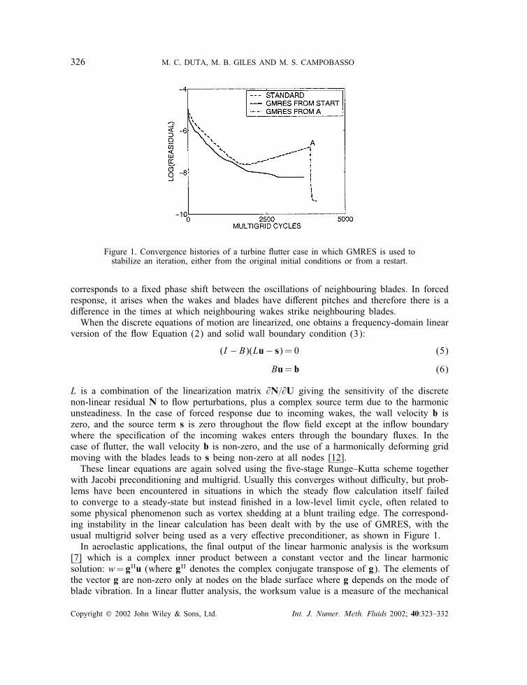
Figure 1. Convergence histories of a turbine �utter case in which GMRES is used tostabilize an iteration, either from the original initial conditions or from a restart.
corresponds to a �xed phase shift between the oscillations of neighbouring blades. In forcedresponse, it arises when the wakes and blades have di�erent pitches and therefore there is adi�erence in the times at which neighbouring wakes strike neighbouring blades.When the discrete equations of motion are linearized, one obtains a frequency-domain linear
version of the �ow Equation (2) and solid wall boundary condition (3):
(I − B)(Lu − s) = 0 (5)
Bu= b (6)
L is a combination of the linearization matrix @N=@U giving the sensitivity of the discretenon-linear residual N to �ow perturbations, plus a complex source term due to the harmonicunsteadiness. In the case of forced response due to incoming wakes, the wall velocity b iszero, and the source term s is zero throughout the �ow �eld except at the in�ow boundarywhere the speci�cation of the incoming wakes enters through the boundary �uxes. In thecase of �utter, the wall velocity b is non-zero, and the use of a harmonically deforming gridmoving with the blades leads to s being non-zero at all nodes [12].These linear equations are again solved using the �ve-stage Runge–Kutta scheme together
with Jacobi preconditioning and multigrid. Usually this converges without di�culty, but prob-lems have been encountered in situations in which the steady �ow calculation itself failedto converge to a steady-state but instead �nished in a low-level limit cycle, often related tosome physical phenomenon such as vortex shedding at a blunt trailing edge. The correspond-ing instability in the linear calculation has been dealt with by the use of GMRES, with theusual multigrid solver being used as a very e�ective preconditioner, as shown in Figure 1.In aeroelastic applications, the �nal output of the linear harmonic analysis is the worksum
[7] which is a complex inner product between a constant vector and the linear harmonicsolution: w= gHu (where gH denotes the complex conjugate transpose of g). The elements ofthe vector g are non-zero only at nodes on the blade surface where g depends on the mode ofblade vibration. In a linear �utter analysis, the worksum value is a measure of the mechanical
Copyright ? 2002 John Wiley & Sons, Ltd. Int. J. Numer. Meth. Fluids 2002; 40:323–332
HARMONIC ADJOINT FOR UNSTEADY FLOW 327
work done on the vibrating blade by the aerodynamic forces generated by the vibration itself.In the forced response analysis, the magnitude of the worksum value is directly proportionalto the amplitude of blade vibration induced by the �ow perturbations.
4. ADJOINT HARMONIC ANALYSIS
The adjoint harmonic approach is founded on the observation that if Au= f then
w= gHu= gHA−1f =((AH)−1g)Hf = vHf (7)
where v is the solution to the adjoint system
AHv= g (8)
This adjoint approach to evaluating the worksum w is bene�cial when there is one g, corre-sponding to a single vibration mode, but several di�erent f vectors, corresponding to di�erentincoming wakes in the case of forced response. In this situation, the usual direct approachwould require a separate linear calculation for each wake, whereas the adjoint approach needsjust one adjoint calculation.To express the linear system of equations in the required form, we add Equations (5)
and (6) to give
((I − B)L+ B)u=(I − B)s+ b (9)
The corresponding adjoint system of equations is therefore
(LH(I − B) + B)v= g (10)
since the real matrix B is symmetric. To implement the adjoint method, it is convenient tosplit v into two orthogonal components¶ using the fact that B is idempotent (i.e. B2 =B):
v= v‖ + v⊥; v‖=(I − B)v; v⊥=Bv (11)
Multiplying Equation (10) by (I − B) yields the equation(I − B)LHv‖=(I − B)g (12)
which can be solved together with the boundary condition
Bv‖=0 (13)
to determine v‖. Multiplying Equation (10) by B yields
v⊥=−BLHv‖ + Bg (14)
so v⊥ can be calculated in a post-processing step before then evaluating the worksum as
w= vHf = vH‖ s+ vH⊥b (15)
¶The reason for the choice of subscript label is that v⊥ is the part of v which is orthogonal to the null-space ofthe matrix B, whereas v‖ is the part that lies within the null-space.
Copyright ? 2002 John Wiley & Sons, Ltd. Int. J. Numer. Meth. Fluids 2002; 40:323–332
328 M. C. DUTA, M. B. GILES AND M. S. CAMPOBASSO
This equation shows that v‖ gives the dependence of the worksum on the distributed harmonicsource term s, whereas v⊥ gives its dependence on the boundary velocities b.It is not obvious how best to solve the adjoint equations. Using the same iterative method
as for the non-linear and linear equations (except with the transpose of the preconditioningmatrix) was found to work well for inviscid �ows, but there were signi�cant stability prob-lems with viscous �ows. To overcome these, Giles analysed the iterative evolution of outputfunctionals such as the worksum product. He found that the adjoint code could be designed togive exactly the same iterative history for the functionals as with the linear code, by properlyconstructing an adjoint version of the usual Runge–Kutta time-marching procedure, and usingadjoint restriction and prolongation operators for the multigrid [13]. This guarantees that thestability and the iterative convergence rate of the adjoint code will be identical to that of thelinear code, which in turn is equal to the asymptotic convergence rate of the non-linear code.The memory requirements and CPU cost per iteration for the adjoint harmonic code are
only slightly larger than those for the linear harmonic code; the increase is associated with amarginally larger cost of evaluating the adjoint �uxes [14]. However, the cost of the adjointsolution is practically identical with that of the linear solution for any application.
5. VALIDATION
One di�culty in the development of an adjoint �ow code is the lack of test cases for val-idation. For the harmonic adjoint code, the validation has been performed at two levels. Atthe lower level, each subroutine has been checked for consistency with its counterpart in thelinear harmonic code [15, 14]. At the higher level, it has been checked that the adjoint andlinear harmonic codes produce the same value for the worksum output, to within machineaccuracy, at each step of the iterative process. This exact equivalence is one advantage of thefully discrete adjoint approach, as opposed to the continuous adjoint approach in which onediscretizes the adjoint partial di�erential equation.The linear harmonic code has itself been validated at a subroutine level by comparison
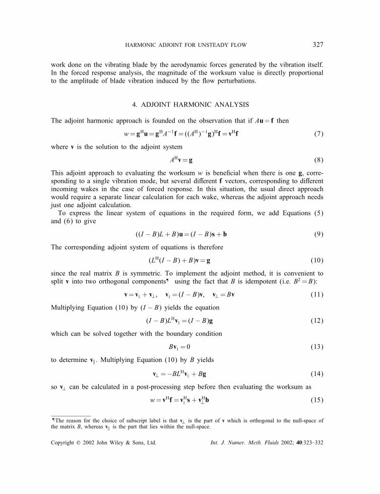
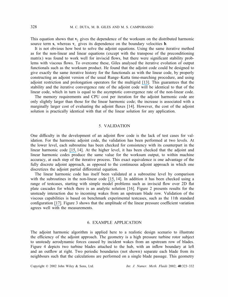
with the subroutines in the non-linear code [15, 14]. In addition it has been checked using arange of testcases, starting with simple model problems such as inviscid �ow over 2D �atplate cascades for which there is an analytic solution [16]. Figure 2 presents results for theunsteady interaction due to incoming wakes from an upstream blade row. Validation of theviscous capabilities is based on benchmark experimental testcases, such as the 11th standardcon�guration [17]. Figure 3 shows that the amplitude of the linear pressure coe�cient variationagrees well with the measurements.
6. EXAMPLE APPLICATION
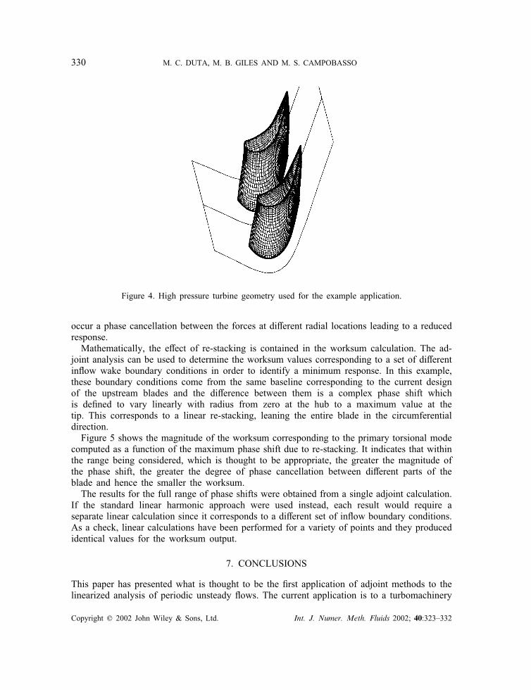
The adjoint harmonic algorithm is applied here to a realistic design scenario to illustratethe e�ciency of the adjoint approach. The geometry is a high pressure turbine rotor subjectto unsteady aerodynamic forces caused by incident wakes from an upstream row of blades.Figure 4 depicts two turbine blades attached to the hub, with an in�ow boundary at leftand an out�ow at right. Two periodic boundaries (not shown) separate each blade from itsneighbours such that the calculations are performed on a single blade passage. This geometry
Copyright ? 2002 John Wiley & Sons, Ltd. Int. J. Numer. Meth. Fluids 2002; 40:323–332
HARMONIC ADJOINT FOR UNSTEADY FLOW 329
Figure 2. Complex components of the �at plate pressure jump due to wake interaction.
Figure 3. First harmonic pressure variation for the 11th standard con�guration.
has been previously employed [4] to show good agreement in the forced response predictedby linear uncoupled and non-linear coupled methods.The design task is to investigate the dependence of the forced vibration upon the shape of
the incoming wakes. In practice, it is very di�cult to signi�cantly reduce the velocity defectin the wakes, but by changing the three-dimensional shape of the upstream blades (e.g. bymoving the tip section of the blade in the circumferential direction while keeping the hubsection �xed, a process known as re-stacking) it is possible to alter the time at which thewake shed by the tip section hits the rotor blade row, relative to that shed from the hubsection. Physically, a wake hitting the blade at the same time at di�erent radial sections willusually produce the maximum structural response, whereas allowing for time delays there may
Copyright ? 2002 John Wiley & Sons, Ltd. Int. J. Numer. Meth. Fluids 2002; 40:323–332
330 M. C. DUTA, M. B. GILES AND M. S. CAMPOBASSO
Figure 4. High pressure turbine geometry used for the example application.
occur a phase cancellation between the forces at di�erent radial locations leading to a reducedresponse.Mathematically, the e�ect of re-stacking is contained in the worksum calculation. The ad-
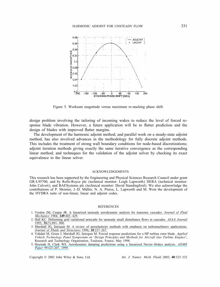
joint analysis can be used to determine the worksum values corresponding to a set of di�erentin�ow wake boundary conditions in order to identify a minimum response. In this example,these boundary conditions come from the same baseline corresponding to the current designof the upstream blades and the di�erence between them is a complex phase shift whichis de�ned to vary linearly with radius from zero at the hub to a maximum value at thetip. This corresponds to a linear re-stacking, leaning the entire blade in the circumferentialdirection.Figure 5 shows the magnitude of the worksum corresponding to the primary torsional mode
computed as a function of the maximum phase shift due to re-stacking. It indicates that withinthe range being considered, which is thought to be appropriate, the greater the magnitude ofthe phase shift, the greater the degree of phase cancellation between di�erent parts of theblade and hence the smaller the worksum.The results for the full range of phase shifts were obtained from a single adjoint calculation.
If the standard linear harmonic approach were used instead, each result would require aseparate linear calculation since it corresponds to a di�erent set of in�ow boundary conditions.As a check, linear calculations have been performed for a variety of points and they producedidentical values for the worksum output.
7. CONCLUSIONS
This paper has presented what is thought to be the �rst application of adjoint methods to thelinearized analysis of periodic unsteady �ows. The current application is to a turbomachinery
Copyright ? 2002 John Wiley & Sons, Ltd. Int. J. Numer. Meth. Fluids 2002; 40:323–332
HARMONIC ADJOINT FOR UNSTEADY FLOW 331
Figure 5. Worksum magnitude versus maximum re-stacking phase shift.
design problem involving the tailoring of incoming wakes to reduce the level of forced re-sponse blade vibration. However, a future application will be to �utter prediction and thedesign of blades with improved �utter margins.The development of the harmonic adjoint method, and parallel work on a steady-state adjoint
method, has also involved advances in the methodology for fully discrete adjoint methods.This includes the treatment of strong wall boundary conditions for node-based discretizations;adjoint iteration methods giving exactly the same iterative convergence as the correspondinglinear method; and techniques for the validation of the adjoint solver by checking its exactequivalence to the linear solver.
ACKNOWLEDGEMENTS
This research has been supported by the Engineering and Physical Sciences Research Council under grantGR=L95700, and by Rolls-Royce plc (technical monitor: Leigh Lapworth) DERA (technical monitor:John Calvert), and BAESystems plc (technical monitor: David Standingford). We also acknowledge thecontributions of P. Moinier, J.-D. M�uller, N. A. Pierce, L. Lapworth and M. West the development ofthe HYDRA suite of non-linear, linear and adjoint codes.
REFERENCES
1. Verdon JM, Caspar JR. A linearized unsteady aerodynamic analysis for transonic cascades. Journal of FluidMechanics 1984; 149:403–429.
2. Hall KC. Deforming grid variational principle for unsteady small disturbance �ows in cascades. AIAA Journal1993; 31(5):891–900.
3. Marshall JG, Imregun M. A review of aeroelasticity methods with emphasis on turbomachinery applications.Journal of Fluids and Structures 1996; 10:237–267.
4. Vahdati M, Green J, Marshall JG, Imregun M. Forced response predictions for a HP turbine rotor blade. AppliedVehicle Technology Panel Symposium on ‘Design Principles and Methods for Aircraft Gas Turbine Engines’,Research and Technology Organisation, Toulouse, France, May 1998.
5. Hoyniak D, Clark WS. Aerodynamic damping predictions using a linearized Navier–Stokes analysis. ASMEPaper 99-GT-207, 1999.
Copyright ? 2002 John Wiley & Sons, Ltd. Int. J. Numer. Meth. Fluids 2002; 40:323–332
332 M. C. DUTA, M. B. GILES AND M. S. CAMPOBASSO
6. Clark WS, Hall KC. A time-linearized Navier–Stokes analysis of stall �utter. Journal of Turbomachinery 2000;122(3):467–476.
7. Duta MC. The use of the adjoint method for the minimization of forced vibration in turbomachinery. Ph.D.Thesis, University of Oxford, 2001.
8. Jameson A. Optimum aerodynamic design using control theory. In Computational Fluid Dynamics Review1995, Hafez M, Oshima K (eds). Wiley: New York, 1995; 495–528.
9. Jameson A. Re-engineering the design process through computation. Journal of Aircraft 1999; 36:36–50.10. Moinier P. Algorithm developments for an unstructured viscous �ow solver. Ph.D. Thesis, University of Oxford,
1999.11. Moinier P, M�uller JD, Giles MB. Edge-based multigrid and preconditioning for hybrid grids. AIAA Paper
99-3339, 1999.12. Hall KC, Clark WS, Lorence CB. A linearized Euler analysis of unsteady transonic �ows in turbomachinery.
Journal of Turbomachinery 1994; 116:477–488.13. Giles MB. On the use of Runge–Kutta time-marching and multigrid for the solution of steady adjoint equations.
Technical Report NA00=10, Oxford University Computing Laboratory, 2000. http://www.comlab.ox.ac.uk/oucl/work/mike.giles/.
14. Giles MB, Duta MC, M�uller JD. Adjoint code developments using the exact discrete approach. AIAA Paper2001-2596, 2001.
15. Giles MB, Pierce NA. An introduction to the adjoint approach to design. Flow, Turbulence and Combustion2000; 65(3=4):393–415.
16. Whitehead DS. Classic two-dimensional methods. In Aeroelasticity in Axial-Flow Turbomachines, Platzer M,Carta FO (eds). vol. 1. AGARD, 1987; AG-298.
17. Fransson TH, Joecker M, Bolcs A, Ott P. Viscous and inviscid linear=non-linear calculations versus quasithree-dimensional experimental cascade data for a new aeroelastic turbine standard con�guration. Journal ofTurbomachinery 1999; 121:717–725.
Copyright ? 2002 John Wiley & Sons, Ltd. Int. J. Numer. Meth. Fluids 2002; 40:323–332
Related Documents