e WHC-SA-3097-FP The Hanford Spent Nuclear Metal Fuel Multi-Canister Overpack and Vacuum Drying & Hot Conditioning Process L. H. Goldmann J. J. Irwin C. R. Miska Date Published May 1996 Prepared for the U.S. Department of Energy Assistant Secretary for Environmental Management Westinghouse P.O BOX 1970 Hanford COfnpany Richland, Washington Manawment and Operations Contractor for the U.S. Department of Energy under Contract DE-AC06-87RL10930 CopyripM hr By aceeptmce of thm hde. the pubkhs mdlor rApiDnt KLnowldoe4 the U.S. Govmrnat's +ht to rsttin a nonoxdusive. roy.ltv-free licase in md to my sop-ht CavMho th- PWM. Approved for public release; distribution is unlimited

Welcome message from author
This document is posted to help you gain knowledge. Please leave a comment to let me know what you think about it! Share it to your friends and learn new things together.
Transcript
e WHC-SA-3097-FP
The Hanford Spent Nuclear Metal Fuel Multi-Canister Overpack and Vacuum Drying & Hot Conditioning Process
L. H. Goldmann J. J. Irwin C. R. Miska
Date Published May 1996
Prepared for the U.S. Department of Energy Assistant Secretary for Environmental Management
Westinghouse P.O BOX 1970 Hanford COfnpany Richland, Washington
Manawment and Operations Contractor for the U.S. Department of Energy under Contract DE-AC06-87RL10930
CopyripM h r By aceeptmce of t h m h d e . the pubkhs mdlor rApiDnt KLnowldoe4 the U.S. Govmrnat's +ht to rsttin a nonoxdusive. roy.ltv-free licase in md to m y sop-ht CavMho th- PWM.
Approved for public release; distribution is unlimited
LEOPL DLXXAlMW M s rspon was prepared as an account of work sponsored by an awncy of the United States Government. Neither the United States Gowmment nor any agency thereof. war any of their employees, nor any of their contractors. subcontractors or their employeas. makes any warranty. eqress or implied. or awmes any lepd liability or responcibility for the eccuracy. completenses, or any third party's use or the resvlts of such use of any informetion, appar~~hls. product. or process disclosed, or rapresents that iks use would not infringe privately owned rights. Reference herein to any specific c o m r c i a l product, process. or seMce b y trade name, trademark. rnanufachlrsr, or otherwise. does not necessarily consrims or imply its endorsement, recommendation, or fawring by the United States Government or any agancy thereof or its contractors or subcontractors. The news and opinions of authors a q r e d herein do wat necessarily slate or reflect those of the United States C o m m e n t or any eQency thereof.
Ttis report has been reproduced from the bssl available copy.
DISCW2.CHP 11-91)
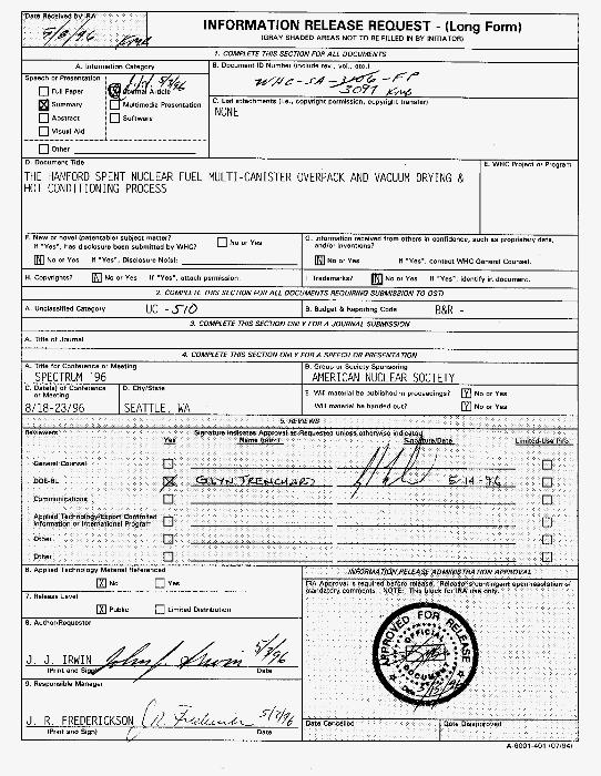
1 COMPLETE THIS SECTlON FOR ALL DOCUMENTS
A information Category B Document ID Number (Include rev , "01 etc 1 Speech or Presentation ,$ $ , y$' 0 Full Paper o nal ArmIe 3077 N+b
Mult,med,s PIBSBnt.t,On C List attachments 11 e , copyright Permission, copvrlght transfer) Summary
0 Abstract 0 Software
0 Visual Aid
NONE
F. New or novel lpatentablel Subject matter?
0 Other
D Document Title
THE HANFORD SPENT NUCLEAR FUEL MULTI-CANISTER OVERPACK AND VACUUM DRYING & E. WHC P m p t or Program
HOT CONDITIONING PROCESS
G. information received from others in confidence, such BE proprietary data.
No or Yes If "Yes". Disclosure NOW:
H. Copyrights7 NO or Yes If "Yes". attach permission.
If "Yes". contact WHC General Counsel.
If '"Yes", identify m document.
No or Yes
I. Tradsmarkr? No or Yes
A. Unclassified Category uc - n o
A-6001-401 1071941
8. Budget & Reporting Code B&R -
A. Title for Conference or Meeting
C. Dateld of Conference SPECTRUM '96
0. CitylState or Meeting
B. Group or Society Sponsoring
AMERICAN NUCLEAR SOCIETY E. Will material be published ~n procsedings? [91 No or Yes
WHC-SA-3097-FP
THE HANFORD SPENT NUCLEAR METAL FUEL MULTI-CANISTER OVERPACK AND VACUUM DRYING Br HOT CONDITIONING PROCESS
Louis H. Goldmann John J. Irwin Curtis R. Miska Westinghouse Hanford Company Westinghouse Hanford Company Westinghouse Hanford Company P. 0. Box 1970 P. 0. Box 1970 Richland. Washington 99352 Richland, Washington 99352 Richland. Washington 99352
P. 0. Box 1970
(SOP) 3736371 (509) 376-0615
BACKGROUND AND INTRODUCTION
Nuclear production reactors operated at the U S . Department of Energy's Hanford Site from 1944 until 1988 to produce plutonium. Most of the irradiated fuel from these reactors was processed onsite to separate and recover the plutonium. When the processiDg facilities were closed in 1992, about 1,900 metric tons of unprocessed irradiated fuel remained in storage. Additional fuel was irradiated for research purposes or was shipped to the Hanford Site from offsite reactor facilities for storage or recovery of nuclear materials. The fuel inventory now in storage at the Hanford Site is predominantly N Reactor irradiated fuel, a metallic uranium alloy that is coextruded into zircaloy-2 cladding.
The Spent NucIear Fuel Project has committed to an accelerated schedule for removing spent nuclear fuel from the Hanford Site K Basins to a new interim storage facility in the 200 Area. Under the current proposed accelerated schedule, retrieval of spent nuclear fuel stored in the K East and West Basins must begin by December 1997 and be completed by December 1999. A key part of this action is retrieving fuel canisters from the water- filled K Basin storage pools and transferring them into multi-canister overpacks (MCOs) that will be used to handle and process the fuel, then store it after conditioning.
The Westinghouse Hanford Company has developed an integrated process to deal with the K Basin spent fuel inventory. The process consists of cleaning the fuel, packaging it into MCOs. vacuum drying it at the K Basins, then transporting it to the Canister Storage Building (CSB) for staging, hot conditioning, and
(509) 372-3743
interim storage. This presentati& de&& the MCO function, design, and life-cycle, including an overview of the vacuum drying and hot conditioning processes.
THE MULTI-CANISTER OVERPACK
Because the MCO has many functions and interfaces, it is the most critical single component for the entire spent fuel removal process and its associated systems. The MCO has the following functions:
Serves as the container for spent nuclear fuel during transport to processing facilities and the new storage facility
Serves as the primaty container during preconditioning storage, with possible monitoring capability for safety and process control
Serves as the primary container during transfer to the conditioning facility
Serves as the process vessel during coId vacuum drying and hot conditioning operations
Serves as the primary container during transfer from the conditioning facility
Serves as the primary container during interim (40-year) storage, with possible monitoring capability for safety and process control
WHC-SA-3097-FP
Potentially serves as the contaiher for process and spent nuclear fuel transport to or disposal in a federal geologic repository.
B e c a m the MCO will serve so many purposes, it must be compatible with a variety of other equipment and facilities. The MCO will interface with equipment and facilities in the following ways:
At the K Basins, pools and loadout facilities and equipment willbe modified to support spent nuclear fuel retrieval, fuel basket loading, MCO loading, and shipment sealing for transfer
The transport package uses the MCO shell as the first containment boundary of the transport packaging
The cold vacuum drying facility uses the MCO as the processing vessel for the spent nuclear fuel
The Canister Storage Building uses the MCO as the primary container inside the storage tubes
The hot conditioning facility uses the MCO as the processing vessel for the spent nuclear fuel
The MCO may provide monitoring equipment for preconditioning storage and dry interim storage
The MCO may also be used as an interface with transport equipment (after interim storage), in a processing facility andlor in a federal geologic repository.
DESCRIPTION OF THE MCO AND PAYLOAD
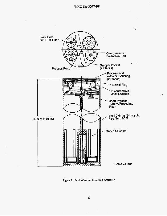
The MCO consists of a 0.61-m (24-in.)-outside- diameter stainless-steel pipe with a 1.3-cm (0.5-in.)-thick wall. See Figure 1. The bottom is flat with a central pocket to allow water to drain from the MCO through the central dip tube. The top is a thick shield plug sealed to the body. The shield plug has passages bored in it to allow for the removal of water, exchange of process gases inside the MCO, and vacuum pumping on the MCO. The MCO is 4.06 m (13 ft 4 in.) long and may contain up to
310,000 cur i s of activity andlor 5,600 kg (15,000 Ibs) of spent nuclear fuel. The maximum loaded weight is about 7,500 kg (20,000 Ibs).
The MCO will stay in the transport cask until it is removed at the CSB. The caskMC0 assemhly together have 20 cm (8 in.) of shielding around the fuel. Together they shield the Operations personnel working around the cask from the fuel. The MCO will be generally free of exterior contamination when it leaves the K Basins.
The cleaned and sorted spent nuclear fuel will be put into rerack baskets, then loaded into the MCO. The following three distinct payloads are dependent on specific element design; the Mark IA and-the Mark IV are from the Hanford Site N Reactor, and the single-pass reactor fuels from the Hanford Site K Reactors are planned for the MCO
0
.
Mark IA Fuel Elements. Forty-eight Mark IA fuel elements will be put into each rerack basket. The baskets normally will be loaded six high into the MCO. The baskets may also contain scrap holders containing fuel fragments. The baskets have a central criticality control void built in to prevent an adverse criticality event during a severe handling accident. The payload for an MCO could be. up to 288 elements. A scrap basket may be used to handle IA scrap fuel and load it into the MCO.
Mark IV Fuel Elements. Fifty-four Mark IV fuel elements will also be put into rerack baskets. The baskets normally will be loaded five high in the MCO. The baskets may also contain scrap holders containing fuel fragments. Because this fuel is of a lower enrichment, these baskets do not need any criticality control features. The payload for a Mark N MCO could be up to 270 fuel elements. A scrap basket may be used to handle IV scrap fuel and load it into the MCO.
Single-Pass Reactor Fuel. Single-pass reactor fuel will be loaded up to 10 tiers high with up to 1,140 elements allowed per
In case of an accident, additional criticality control for the loaded MCO is maintained by limiting its girth to
2
WHC-SA-3097-FP
the quivalent of approximately a 63.5-m- (25-in.)- circle. The MCO, with its components and rerack baskets, will be made almost entirely of 304L stainless steel.
LIFE CYCLE OF AN MCO
The use of an MCO will begin at the CSB where a new, empty MCO shell and bottom will be loaded into the transport cask and prepared for shipment to the K Basins.
At the K Basins, the cask and empty MCO will be prepared for loading and submerged in the loadout pit. The cask and MCO assembly will be bagged so that only the interior and sealing neck of the MCO will be wetted by the basin water when the entire assembly is submerged. Simultaneously fuel will be prepared for loading into the MCO at the fuel retrieval area.
Fuel retrieval operations will begin with the spent nuclear fuel in canisters in the basin. The canisters will be retrieved, canisters from the K West Basins will have the canister lids removed, and the fuel will be removed from the canisters. The canisters and fuel will be thoroughly cleaned to remove the fuel particulates and corrosion products from the spent nuclear fuel. Fuel particulates and corrosion products could be released during canister opening in the K West Basin and during fuel and canister cleaning. These materials will be captured and contained immediately to keep them out of the water in the basin proper and off the basin floor. The empty canisters will be moved to an area in the basin for disposal by the debris removal project. Then the cleaned fuel will be reracked in a freedraining open fuel basket and queued for later MCO loading.
The MCOs will be loaded with baskets five or six high. They will be loaded undewater using remote or automated means to reduce the dose to personnel. After loading, the MCOs will be prepared for sealing. The loaded MCO and cask will be kept upright during all handling, transport, and process operations.
The shield plug assembly, including the dip tubes, will be placed into the MCO. The cask and MCO assembly will be raised from the water, and the shield plug sealed securely into position by a welding machine or other closure device. If the MCO is sealed by welding at the K Basins, the welding machine probably will be positioned manually, then operated remotely to reduce the dose to the operator. After being inspected, the cask and sealed MCO will be placed on the conveyance for transfer to the cold vacuum drying facility. The cask will be
manually closed and sealed before beiig loaded onto the over-the-road conveyance for transfer to the cold vacuum drying facility. To minimize dose, powered overhead cranes and powered hand tools will be'used to the greatest extent practicable to close, seal, load, and secure the shipping cask.
The following alternative plan was devised for moving the flooded MCO to the cold vacuum drying facility. The shield plug would be installed in the MCO at the loadout pit and secured to the MCO in the cask. Later, at the cold vacuum drying facility, it would be welded to the MCO.
- .. The drying operations will be conducted at the
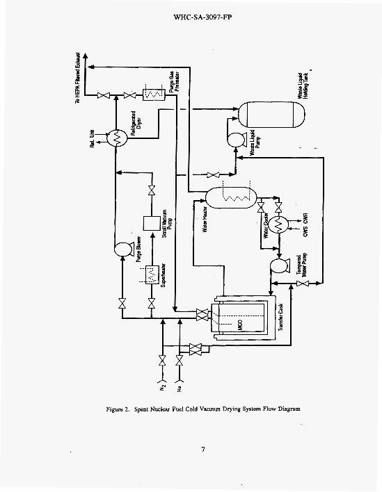
K Basin spent nuclear fuel cold vacuum drying facility, which is located inside the protected area of the K B a s k . The drying operations will be conducted to remove the water from the MCO and dry the fuel enough so that it can be safely transported to the CSB for continued processing. The drying operation will begin when the MCOs containing fuel and water are received at the vacuum drying facility. The MCOs will be connected to transfer piping and a MCOlcask heating system. The MCOs will be heated to 50 OC to facilitate drying, drained of bulk water, then evacuated to a low vacuum to remove residual free water. Wben the drying step is complete, the MCOs will be cooled, backfilled with an inert gas, and sealed. The cold vacuum drying facility schematic is depicted in Figure 2 and will likely require the following elements:
Process Area. The process area will contain the cold vacuum drying process. It will be used to isolate the MCOs being dried physically, thermally, and radiologically from other MCOs, workers, and the environment. The process area must also provide an interface with the MCOlcask transporter.
Process Control System. The process control system monitors and controls the function and operation of the cold vacuum drying process equipment. This system includes the instrumentation to; monitor the pressure, temperature, and gas composition at critical points of the process; to monitor the status of equipment; and to monitor the offgases for radioactive contamination.
Process Station. The process station is the structure that will hold the MCO during the
3
WHC-SA-3097-FP
cold vacuum drying process. It consists of equipment to heat or cool the MCO; structural steel, load-hearing walls to support the process area; transporter entrance doors; and radiation shielding.
Process Heating System. The process heating system will control the temperature of the MCO during the cold vacuum drying. It consists of electrically heated water surrounding the MCO in the transport cask and the additional equipment and controls needed to efficiently heat or cool the MCO to operating temperature.
Vacuum Pumping System. The vacuum pumping system will reduce the pressure in the MCO to the low vacuum range during cold vacuum drying process. It consists of vacuum pumps, piping, valves, and filters that will he. used to achieve and maintain the required operating pressures in the MCO.
Process Gas System. The process gas system will be used to control uranium reactions during cold vacuum drying, and to backfill the MCO before it is transferred to Staging. It consists of a gas bottle station, handling equipment, fixtures, piping, and control valves. Process gases will be supplied to each process station from a central gas bottle station.
Process Offgas System. The process offgas system will filter all air flows discharged by the cold vacuum drying process. It consist of air ducts, dampers, controls, two stages of testable high- efficiency particulate air (HEPA) filters, a fan, and an exhaust stack. It receives the offgas from each process station and filters the gas through two redundant HEPA filter trains before discharge.
Solid and Liquid Waste Handling System. The solid and liquid waste handling system will provide for the disposal of solid or liquid waste generated during the processing, including bulk MCO water, HEPA filters, failed equipmenf, and decontamination supplies.
After vacuum drying, the cask and loaded MCO will be transported to the CSB. They will he unloaded from the conveyance and put in an operations service pit where the cask will be opened and the'MC0 vented and prepared for staging (short-tern storage). An MCO handling machine (MHM) will be positioned above the MCO and the MCO will be pulled from the cask up into the MHM and confined by a MHM closure valve. Then the MHM will move the MCO to a storage location in the CSB to await hot conditioning. The CSB storage tubes will be inerted after the MCO is placed in the tube, and the tube atmosphere will be monitored periodically. A new, empty MCO will then be loaded into the cask and the cask and empty MCO sent b s k @the K Basins for another fuel loading and shipping cycle.
When hot vacuum conditioning process equipment is available, the staged MCOs will be retrieved individually from the CSB storage tubes and processed. Once in the hot vacuum conditioning process area, the MCOs containing previously vacuumdried fuel will be connected to process piping, an inert gas flow will be established, and the fuel will he heated to approximately 300 "C. The fuel will be held under vacuum at this temperature to remove residual free water and water chemically bound to the fuel. The process will also decompose uranium hydride present with the metallic fuel, releasing hydrogen from the fuel.
After drying and hydride decomposition at 300°C are complete, the MCO and fuel will he cooled down, and a controlled concentration of oxygen in inert gas will be added to the MCO to allow a slow controlled partial oxidation of highly chemically reactive fuel surfaces. 'Ibis controlled partial oxidation, called passivation, will reduce the overall chemical reactivity of the fuel. When the passivation step is complete, the MCO will he cooled, backfilled with inert gas, and sealed. After the hot conditioning process is complete, the MCO will be transferred hack to a CSB storage tube, and the storage tube inerted.
Hot vacuum conditioning will likely require the following process elements:
0 Process Area. The process area contains the hot vacuum conditioning process. It will be used to isolate the MCOs being conditioned physically, thermally, and radiologically from other MCOs, workers, and the environment. The process area
4
WHC-SA-3097-FP
must also provide 80 interface with the Canister Storage Building MCO transfer machine.
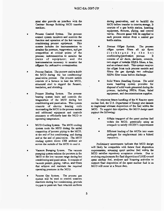
Process Control System. The process control system monitors and controls the function and operation of the hot vacuum conditioning process equipment. This system includes the instrumentation to monitor the pressure, temperature, and gas composition at critical points of the process; instrumentation to monitor the status of equipment; and the instrumentation necessary to monitor the offgases for radioactive contamination.
Process Station. The process station holds the MCO during the hot conditioning/ passivation process. The process station consists of a furnace to heat the MCO, structural steel to support the furnace, insulation, and shielding.
Process Heating System. The process heating system heats and controls the temperature of the MCO during hot conditioning and passivation. This system consists of electric heating coils surrounding the MCO in the process station and additional equipment and controls necessary to efficiently heat the MCO to operating temperahre.
MCO Cooling System. The MCO cooling system cools the MCO during the initial connection of process piping to the MCO, at the end of hot conditioning, and during and at the end of passivation. The MCO cooling system draws CSB ambient air across the outside of the MCO to cool it.
Vacuum Pumping System. The vacuum pumping system reduces the pressure in the MCO to the low vacuum range during hot conditioning and passivation. It consists of vacuum pumps, piping, valves, and filters that achieve and maintain the required operating pressures in the MCO.
Process Gas System. The process gas system will be used to control uranium reactions during hot conditioning, provide oxygen to passivate hare uranium surfaces
during passivation, and to backfill the MCO before transfer to interim storage. It consists of a gas bottle station, handling equipment, fixtures, $ping, and control valves. Process gases will be supplied to each process statim from a central gas bottle station.
Process Offgas System. The process offgas system filters all air flows d i s c h a r g e d b y t h e h o t conditioninglpassivation process. It consists of air ducts, dampers, controls, two stages of testable HEPA filters, a fan, and an exhaust stack. This system receives the offgas from each process module and filters the gas through two redundant HEPA filter trains before discharge.
Solid Waste Handling System. The solid waste handling system provides for disposal of solid waste generated during the process, including HEPA filters, failed equipment, and decontamination supplies.
To minimize future handling of the N Reactor spent nuclear fuel, the US. Department of Energy also intends to implement ultimate disposition of the fuel within the MCO. To support this objective, the MCO design must support the following:
Offsite transport of the spent nuclear fuel within the MCO, potentially using an overpack to satisfy 1OCFR71 requirements
Efficient loading of the MCOs into waste packages for emplacement into a federal repository.
Preliminary assessments indicate that MCO design will likely be compatible with future final disposition requirements, assuming spent nuclear fuel within the MC.0 satisfies repository acceptance criteria. Due to evolving requirements for final disposition of DOE-owned spent nuclear fuel, analyses and licensing activities to support f d disposition of the spent nuclear fuel in an MCO will occur at a future date.
5
WHC-SA-3097-FP
Vent Port w/HEPA Filter
- .
Process Ports' 7
A
4.06 m (160 in.)
L Shell 0.61 m (24 in.) dia. Pipe Sch. 80 S
Mark 1A Basket
Scale = None
Figure 1. Multi-Canister Overpack Assembly
6
WHC-SA-3097-FP
Figure 2. Spent Nuclear Fuel Cold Vacuum Drying System Flow Diagram
I

WHC-SA-3097-FP
This page intentionally left blank.
8
Number of Couies
ONSITE
25
WHC-SA-3097-FP
DISTRIBUTION
Westinehouse Hanford Company
F. W. Bradshaw G. E. Culley D. R. Duncan J. E. Filip J. R. Frederickson L. H. Goldmann (15 copies) J. J. Irwin C. R. Miska G. D. Trenchard Central Files DPC
R3-85 R3-86 R3-86 R3-85 R3-86 R3-86 h0-34 R3-86 57-41 A3-88 A3-94
Distr-1

WHC-SA-3097-FP
This page intentionally left blank.
Distr-2
Related Documents