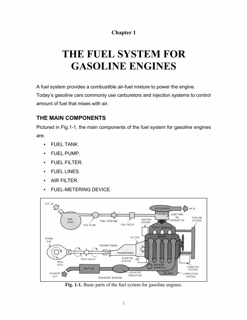
Chapter 1 THE FUEL SYSTEM FOR GASOLINE ENGINES A fuel system provides a combustible air-fuel mixture to power the engine. Today’s gasoline cars commonly use carburetors and injection systems to control amount of fuel that mixes with air. THE MAIN COMPONENTS Pictured in Fig.1-1, the main components of the fuel system for gasoline engines are: • FUEL TANK. • FUEL PUMP. • FUEL FILTER. • FUEL LINES. • AIR FILTER. • FUEL-METERING DEVICE. Fig. 1-1. Basic parts of the fuel system for gasoline engines. 1

Welcome message from author
This document is posted to help you gain knowledge. Please leave a comment to let me know what you think about it! Share it to your friends and learn new things together.
Transcript
Chapter 1
THE FUEL SYSTEM FOR GASOLINE ENGINES
A fuel system provides a combustible air-fuel mixture to power the engine.
Today’s gasoline cars commonly use carburetors and injection systems to control
amount of fuel that mixes with air.
THE MAIN COMPONENTS
Pictured in Fig.1-1, the main components of the fuel system for gasoline engines
are:
• FUEL TANK.
• FUEL PUMP.
• FUEL FILTER.
• FUEL LINES.
• AIR FILTER.
• FUEL-METERING DEVICE.
Fig. 1-1. Basic parts of the fuel system for gasoline engines.
1

FUEL TANK
An automotive fuel tank must be safely held. It is normally mounted in the rear of
the car, under the trunk or rear seat. See Fig. 1-2. The function of fuel tank is to
store the gasoline and supply fuel during engine operation. Fuel tanks are usually
made of thin sheet of metal or plastic. An average fuel tank capacity is around 12
to 25 gallons (45 to 95 liters). Fuel tank caps are sealed to prevent the escape of
fuel and fuel vapors from the tanks. This cap has pressure and vacuum valves
that only open under abnormal conditions of high pressure or high vacuum. See
Fig. 1-3.
Fig. 1-2. Basic parts of fuel tank.
Fig. 1-3. Fuel tank cap.
2

The gasoline tank contains a float, which is attached to resistance device. See
Fig. 1-4. The travel of the float up and down causes the resistance to vary. Low
fuel level causes float to move down; as a result, tank unit has high resistance.
Low current flow does not heat bi-metal strip and therefore, gauge shows low.
When the tank is full, this makes the float to move up. On the other hand, the
resistor moves in low resistance position. High current flows through gauge and
tank unit heats bi-metal strip. Strip bends and moves needle to full.
Fig. 1-4. Fuel gauge operation.
FUEL PUMP
A fuel pump draws fuel from the tank and forces it to the fuel’s metering device.
There are two basic types of fuel pumps, mechanical and electrical pumps.
Mechanical fuel pump
An eccentric lobe of the engine camshaft usually powers a mechanical fuel
pump. Mechanical fuel pump is commonly used with carburetor type fuel system.
The mechanical fuel pump consists of a rocker arm, return spring, diaphragm,
3
F

Fig. 1-5. Basic parts and operations of mechanical fuel pump.
diaphragm spring, and check valves. See Fig. 1-5. When the eccentric lobe is
pushed on the rocker arm, this pulls the diaphragm down and compresses the
diaphragm spring. Since the area in the pumping chamber increases, a vacuum
pulls fuel through the inlet check valve. This fills the pump with fuel. When the
eccentric lobe rotates away from the pump rocker arm, this releases the
diaphragm. The diaphragm spring then pushes on the diaphragm and
pressurizes the fuel in the pumping chamber. The fuel flows out the outlet check
valve to the carburetor.
4

Electric fuel pump
An electric fuel pump, like a mechanical fuel pump, produces fuel pressure and
flow for the fuel-metering device of a fuel system. Electric fuel pumps are
commonly used in gasoline fuel injection systems. An electric fuel pump can be
located inside the fuel tank or between the tank and the engine. There are three
common types of electric fuel pumps, an impeller, a roller vane, and sliding vane.
See Fig. 1-6.
Fig. 1-6. Electric fuel pumps types and operations.
Impeller electric fuel pump
This is a centrifugal type pump. Normally, it is located inside the fuel tank. This
pump uses a small D.C. motor to spin the impeller. The impeller blades cause
the fuel to fly outward due to centrifugal force. This produces enough pressure to
move the fuel through the fuel lines.
Roller vane electric fuel pump
This is a positive displacement pump (each pump rotation moves a specific
amount of fuel).
When the rotor disc and rollers spin, they pull fuel in one side. Then the fuel is
trapped and pushed to a smaller area on the opposite side of the pump housing.
This squeezes the fuel between the rollers and the fuel flows out under pressure.
5
.
Sliding vane electric fuel pump
A sliding vane electric fuel pump is similar to a roller vane pump. Vanes (blades)
are used instead of rollers.
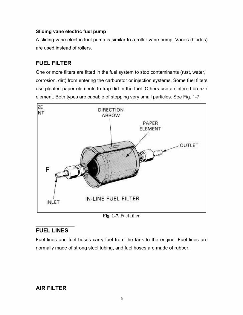
FUEL FILTER
One or more filters are fitted in the fuel system to stop contaminants (rust, water,
corrosion, dirt) from entering the carburetor or injection systems. Some fuel filters
use pleated paper elements to trap dirt in the fuel. Others use a sintered bronze
element. Both types are capable of stopping very small particles. See Fig. 1-7.
Fig. 1-7. Fuel filter.
FUEL LINES
Fuel lines and fuel hoses carry fuel from the tank to the engine. Fuel lines are
normally made of strong steel tubing, and fuel hoses are made of rubber.
AIR FILTER
6

The function of an air filter is to remove dirt and dust from the air entering the
engine intake manifold. Most air filters are made of paper element. See Fig. 1-8.
Fig. 1-8. Air filter.
FUEL - METERING DEVICE
A fuel-metering device which controls the amount of fuel that mixes with air.
The fuel-metering device for gasoline engines is divided into two systems:
• CARBURETOR SYSTEM.
• FUEL INJECTION SYSTEM.
CARBURETOR SYSTEM
7
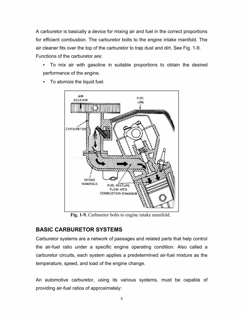
A carburetor is basically a device for mixing air and fuel in the correct proportions
for efficient combustion. The carburetor bolts to the engine intake manifold. The
air cleaner fits over the top of the carburetor to trap dust and dirt. See Fig. 1-9.
Functions of the carburetor are:
• To mix air with gasoline in suitable proportions to obtain the desired
performance of the engine.
• To atomize the liquid fuel.
Fig. 1-9. Carburetor bolts to engine intake manifold.
BASIC CARBURETOR SYSTEMS
Carburetor systems are a network of passages and related parts that help control
the air-fuel ratio under a specific engine operating condition. Also called a
carburetor circuits, each system applies a predetermined air-fuel mixture as the
temperature, speed, and load of the engine change.
An automotive carburetor, using its various systems, must be capable of
providing air-fuel ratios of approximately:
8

• 8 : 1 for cold engine starting.
• 16 : 1 for idling.
• 15 : 1 for part throttle.
• 13 : 1 for full acceleration.
• 18 : 1 for normal cruising at highway speeds.
The seven basic carburetor systems are:
• FLOAT SYSTEM (maintains supply of fuel in carburetor bowl).
• IDLE SYSTEM (provides a small amount of fuel for low speed engine
operation).
• OFF-IDLE SYSTEM (provides correct air-fuel mixture slightly above idle
speeds).
• ACCELERATION SYSTEM (squirts fuel into air horn when throttle valve
opens and engines speed increases).
• HIGH-SPEED SYSTEM (supplies lean air-fuel mixture at cruising speeds).
• FULL-POWER SYSTEM (enriches fuel mixture slightly when engine
power demands are high).
• CHOKE SYSTEM (provides extremely rich air-fuel mixture for cold engine
starting).
FLOAT SYSTEM
Function: To maintain the correct level of fuel in carburetor bowl, and to supply
fuel for all circuits.
Parts: Fuel bowl, float, needle valve, needle seat, and bowl vent. See Fig. 1-10.
Operation: When the engine speed or load increases, fuel is rapidly pulled out of
the fuel bowl and into the venturi. This makes the fuel level and float drop in the
bowl. The needle valve also drops away from its seat. The fuel pump can then
force more fuel into the bowl. As the fuel level in the bowl rises, the float pushes
the needle valve back into the seat. When the fuel level is high enough, the float
9

closes the opening between the needle valve and seat. With the engine running,
the needle valve usually lets some fuel leak into the bowl.
Fig. 1-10. Basic parts and operations of the float system.
IDLE SYSTEM
Function: To provide a small amount of fuel for low speed engine operation.
(At speeds below approximately 800 r.p.m. or 20 M.P.H. (32 km/hr)).
Parts: Main discharge tube, a low speed jet, idle air bleed, idle passage, idle
port, bypass, economizer, and an idle mixture screw. See Fig. 1-11.
Operation: For the idle system to function, throttle plates must be closed. Then
high intake manifold vacuum below throttle plates pulls fuel out idle port. Mixture
screw allows adjustment of mixture at idle. Air bleed helps premix air with fuel,
and to atomize the liquid fuel.
10

Fig. 1-11. Basic parts and operations of idle system.
OFF-IDLE SYSTEM
Function: To feed more fuel when the throttle plates are partially open.
(Above approximately 800 r.p.m. or 20 M.P.H. (32 km/hr)).
Parts: Main discharge tube, a low speed jet, idle air bleed, idle passage, idle
port, bypass, economizer, off-idle port, and an idle mixture screw. See Fig. 1-12.
11

Fig. 1-12. Basic parts and operations of the off-idle system.
Operation: The off-idle system begins to function when the driver presses lightly
on the gas pedal. As the throttle plates open, they expose the off-idle ports to
intake manifold vacuum. Vacuum then begins to pull fuel out of the idle screw
port and off-idle ports. This provides enough extra fuel to mix with the additional
air flowing around the throttle plates.
ACCELERATION SYSTEM
12

Function: To provide extra fuel when changing from the idle circuits to the high-
speed circuits. The acceleration system squirts a stream of extra fuel into air horn
whenever the gas pedal is pressed.
Parts: Pump linkage, acceleration pump, pump check ball, pump reservoir, pump
check weight, and pump nozzle. See Fig. 1-13.
Operation: When the driver presses the gas pedal, the throttle plates open. This
causes the acceleration pump piston or diaphragm to compress the fuel in the
pump reservoir.
Acceleration pump pressure closes the pump check ball and fuel flow toward the
pump check weight. Pressure lifts the pump check weight off its seat and fuel
squirts into the carburetor air horns. As the gas pedal is released, the pump
piston or diaphragm retracts. This closes the pump check weight and opens the
pump check ball. Fuel flows out of the bowl to refill the acceleration pump
reservoir.
Fig. 1-13. Basic parts and operations of the acceleration system.
HIGH-SPEED SYSTEM
13

Function: To supply the engine air-fuel mixture at normal cruising speeds.
This circuit begins to function when the throttle plates are open wide enough for
venturi.
It functions from about 20 to 55 M.P.H. (32 to 89 km/hr) or 2000 to 3000 r.p.m.
Parts: Main jet, main discharge passage, air bleed, and venturi. See Fig. 1-14.
Operation: When engine speed is high enough, airflow through the carburetor
forms a high vacuum in the venturi. The vacuum pulls fuel through the main jet.
Fuel flows through the main jet, which meters the amount of gasoline entering
the circuit. Then, the fuel flows into the main discharge passage, and finally
pulled out the main nozzle into the engine after mixing with the air.
Fig. 1-14. Basic parts and operations of the high speed system.
FULL- POWER SYSTEM
Function: To provide a means of enriching the fuel mixture for high speed, high
power conditions.
Parts: Main jet, metering rod linkage, metering rod, main discharge passage, air
bleed, and venturi. See Fig. 1-15.
14

Fig. 1-15. Basic parts and operations of the full power system.
Operation: When gas pedal is pushed down for full power, throttle linkage acts
on metering rod linkage. Metering rod is lifted out of main jet to add more fuel to
the mixture. When gas pedal is released, the metering rod will move down inside
the main jet, flow is restricted and leaner fuel mixture results.
Either mechanical linkage or engine vacuum can be used to operate a metering
rod.
CHOKE SYSTEM
Function: To supply an extremely rich air-fuel ratio to aid cold engine starting.
For fuel mixture to burn properly, the fuel entering the intake manifold must
atomize and vaporize. When the engine is cold, the fuel entering the intake
manifold tends to condense into liquid .As a result, not enough fuel vapors enter
the combustion chambers and the engine could miss or stall when cold. A choke
is used to prevent this lean condition.
15

Parts: Choke plate's valve, thermostatic spring, and other parts depending upon
choke design. See Fig. 1-16.
Fig. 1-16. Basic parts and operations of the choke system.
Operation: When engine is cold, thermostatic spring closes choke plates. High
vacuum below choke pulls large a mount of fuel out main discharge. When
engine warms, hot air causes thermostatic spring to open choke plates.
TYPES OF THE CARBURETORS
Automotive carburetors are available in single barrel, two-barrel (two air horns in
single body), and four-barrel (four air horns in one body) designs. All are
illustrated in Fig. 1-17.
Multiple barrel carburetors are used to provide increased “engine breathing” (air
intake). The amount of fuel and air that enters the engine is a factor limiting
engine horsepower output. Extra carburetor barrels allow more air and fuel into
the engine at wide-open throttle. This allows the engine to develop more power.
16

Fig. 1-17. Types of the carburetors.
Carburetor primary and secondary circuits
Two-barrel and four-barrel carburetors are divided into two sections: the primary
and the secondary circuits.
17
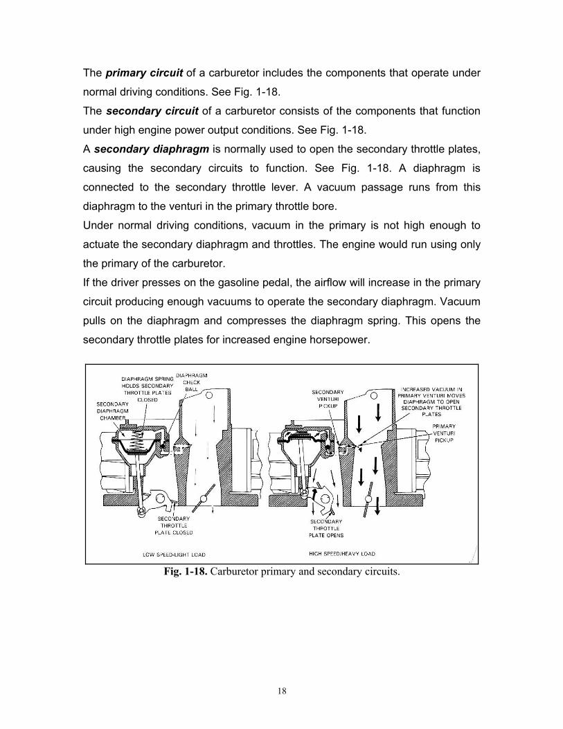
The primary circuit of a carburetor includes the components that operate under
normal driving conditions. See Fig. 1-18.
The secondary circuit of a carburetor consists of the components that function
under high engine power output conditions. See Fig. 1-18.
A secondary diaphragm is normally used to open the secondary throttle plates,
causing the secondary circuits to function. See Fig. 1-18. A diaphragm is
connected to the secondary throttle lever. A vacuum passage runs from this
diaphragm to the venturi in the primary throttle bore.
Under normal driving conditions, vacuum in the primary is not high enough to
actuate the secondary diaphragm and throttles. The engine would run using only
the primary of the carburetor.
If the driver presses on the gasoline pedal, the airflow will increase in the primary
circuit producing enough vacuums to operate the secondary diaphragm. Vacuum
pulls on the diaphragm and compresses the diaphragm spring. This opens the
secondary throttle plates for increased engine horsepower.
Fig. 1-18. Carburetor primary and secondary circuits.
18

CARBURETOR PROBLEMS
Poor Engine Performance
• Air leak at carburetor or intake manifold.
• Air leak in fuel line.
• Clogged or dirty carburetor air filter.
• Clogged fuel lines or fuel filter.
• Defective fuel pump.
• Incorrect fuel level in fuel bowl.
• Dirt in carburetor jets and passages.
• Worn or inoperative accelerating pump.
• Defective gaskets in carburetor.
• Clogged exhaust system.
• Leaking vacuum lines.
Poor Idling
• Incorrect adjustment of idle mixture screw.
• Incorrect float level.
• Sticking float needle valve.
• Defective gasket between carburetor and intake manifold.
• Defective gaskets in carburetor.
• Loose carburetor- to – intake manifold nuts.
• Loose intake manifold attaching bolts.
• Idle discharge holes partly clogged.
• Leaking vacuum lines to accessory equipment.
• Clogged air cleaner.
• High float level
Hard Starting
• Incorrect choke adjustment.
• Defective choke.
• Incorrect float level.
• Defective fuel pump.
19
Poor Acceleration
• Accelerator pumps inoperative.
• Accelerator pump leather hard or worn.
• Clogged accelerator jets or passages.
• Defective ball checks in accelerator system.
• Incorrect fuel level.
Carburetor Floods
• Float level too high.
• Stick float needle valve.
• Defective gaskets in carburetor.
• Cracked carburetor body.
Excessive Fuel Consumption
• Incorrect adjustment of idle mixture screw.
• Fuel leaks in carburetor or lines.
• Dirty air cleaner.
• High float level.
• Dirty carburetor.
20

GASOLINE INJECTION SYSTEM
A gasoline injection system has several possible advantages over a carburetor
type fuel system. A few of these include:
• Improved atomization (fuel is forced into intake manifold under pressure
which helps break fuel droplets into a fine mist).
• Better fuel distribution (more equal flow of fuel into each cylinder).
• Smoother idle (lean fuel mixture can be used without rough idle because
of better fuel distribution).
• Improved fuel economy (high efficiency because of more precise fuel
metering, atomization, and distribution).
• Lower emissions (efficient air-fuel mixture reduces exhaust pollution).
• Better cold weather driveability (injection provides better control of mixture
enrichment than a carburetor choke).
• Increased engine power (precise metering of fuel to each cylinder can
result in more horsepower output).
Gasoline injection systems can be divided into two main groups: MULTI - POINT
FUEL INJECTION, and SINGLE – POINT FUEL INJECTION. This classification
is based on the number and positions of injectors:
• MULTI-POINT FUEL INJECTION SYSTEM, also called port injection, has
separate injectors for each cylinder; each injector positioned close to inlet
valve of the engine. Gasoline is sprayed into each intake port and toward
each engine intake valve. See Fig. 1-19-B.
• SINGLE-POINT FUEL INJECTION SYSTEM, has the injector nozzle in
throttle body assembly on top of the engine. Fuel is sprayed into the top,
center of the intake manifold. See Fig. 1-19-A.
Most gasoline injection systems are indirect injection. This means that the fuel is
sprayed into the intake manifold ports.
21

Fig. 1-19-A. Single-point fuel injection. B. Multi-point fuel injection.
MULTI-POINT FUEL INJECTION SYSTEM
There are two common types of multi-point fuel injection systems: HYDRAULIC-
MECHANICAL FUEL INJECTION SYSTEM and ELECTRONIC FUEL
INJECTION SYSTEM.
MULTI-POINT HYDRAULIC- MECHANICAL FUEL INJECTION
SYSTEM
Hydraulic-mechanical fuel injection system is a continuous injection system that
sprays fuel into the intake manifold all of the time. Anytime the engine is running,
some fuel is forced out of the injector nozzle and into the engine.
Hydraulic-mechanical fuel injection system is an indirect injection. This means
that the fuel is sprayed into the engine intake manifold ports.
There are two common types of hydraulic- mechanical fuel injection systems: K-
Jetronic and KE - Jetronic.
K- JETRONIC SYSTEM
Hydraulic-mechanical type K-Jetronic feeds fuel through all of the injectors, all
the time. Anytime the engine is running, some fuel is forced out of the injector
nozzle and into the engine. The system controls fuel flow, not by means of an
electronic control unit but by using a fuel distributor, mechanically controlled by a
hinged airflow sensor. System operating pressures range from around 50 – 60
psi. See Fig. 1-20.
22

Fig. 1-20. Hydraulic-mechanical fuel injection type K-Jetronic.
Operation
On starting the engine, the electric fuel pump draws gasoline out of the tank and
passes it to the accumulator. See Fig. 1-20. After passing accumulator, the
pressurized fuel will be entering the fuel filter and then to the fuel distributor. Fuel
distributor and airflow sensor controls the quantity of the fuel delivered to the
injectors. At idle, low airflow only moves sensor plate a little. Lever arm pushes
up lightly on the fuel control plunger and opens a slit to allow fuel to the chamber.
Although fuel pressure now acts on both sides of the diaphragm, the force of the
spring moves the diaphragm downwards and opens the valve at the center of the
diaphragm to release the fuel to the injector. The flow of fuel from the chamber
slightly lowers the downward force on the diaphragm, so a valve-open position is
reached, which corresponds to the amount that the control plunger is moved.
Opening the throttle plate will give a greater air flow, so the disc will raise further,
which, in turn, will raise the control plunger and allow more fuel to pass to the
chamber. These extra fuel flows will more than make up for the fuel that is
escaping past the valve to the injector, so the extra downward force produced by
23

the fuel pressure lowers the diaphragm, opens the valve further and increases
the quantity of fuel going to the injector.
Fuel distributor and airflow sensor
This controls the quantity of fuel delivered to the injectors. The air sensor, see
Fig.1-21, consists of a venturi (1) in the induction pipe into which is fitted a
movable disc (2). Attached to the disc is a counter-balanced lever (3), which acts
on a control plunger (4). Mounted around the plunger are a number of diaphragm
valves (5), one for each injector. The purpose of these valves is to provide a fuel
supply to the injectors that are proportional to the movement of the control
plunger.
Fig. 1-21. K-Jetronic fuel distributor and airflow sensor.
24
Continuous fuel injector
A continuous fuel injector is simply a spring-loaded valve. See Fig. 1-22. It injects
fuel all the time when the engine is running. A spring holds the valve in a
normally closed position. A filter in the injector traps dirt. The injector is usually
push-fitted into rubber bushings in the cylinder head or intake manifold. With the
engine off, the injector spring holds the injector valve closed. This prevents fuel
from dripping into the engine. When the engine is running, fuel pressure builds
from fuel distributor pushes the injector valve open. A steady stream of gasoline
then sprays toward each engine intake valve. The fuel is pulled into the engine
when the intake valves open.
Fig. 1-22. Continuous injector.
Fuel accumulator
The fuel accumulator is spring-loaded diaphragm used in an injection system to
dampen pressure pulses of the pump. See Fig. 1-23. The accumulator may also
maintain pressure when the engine is shut down. This aids faster engine
restarting.
Fig. 1-23. Fuel accumulator.
Warm-up regulator
25
This controls the mixture enrichment during engine warm-up. It consists of a
valve, operated by a bimetallic strip. See Fig. 1-24. When the engine is cold,
open valve reduce pressure acting on the end of plunger. This tends to increase
fuel mixture. During warm-up, electrical current heats bi-metal strip and gradually
closes valve.
Fig. 1-24. Warm-up regulator.
Thermo – time switch
Thermo – time switch energizes cold start injector when engine temperature is
low enough. See Fig. 1-25. Cold start injector then sprays extra fuel into engine
to help keep the cold engine running smoothly. When engine warms enough,
thermo-time switch opens the circuit to shut off injector.
Fig. 1-25. Basic cold start injector, thermo-time switch circuit.
Cold-start injector
26
A cold-start injector is an additional fuel injector valve used to supply extra
gasoline for cold engine starting. See Fig. 1-26. Thermo-time switch is used to
operate cold-start injector.
Fig. 1-26. Cold-start injector.
Idle air bypass valve
The idle air bypass valve is operated by a bimetallic spring or expansion
element. The function of this valve is to supply more air to engine during the
warm-up. The additional airflow causes a greater deflection of the airflow meter
plate. This causes the engine to idle at a higher speed during warm-up, as a
result of which it runs smoothly. When the engine warms up, this valve closes off.
The idle air bypass valve is designed somewhat like a sliding gate valve in that it
should be fully open on a cold engine and closed on a warm engine.
See Fig.1-27.
Fig. 1-27. Idle air bypass valve.
Fuel pressure regulator
27

The function of fuel pressure regulator is to maintain constant fuel pressure
entering fuel distributor. The fuel pressure regulator consists of a fuel valve, and
spring. See Fig. 1-28. When fuel pressure is low (initial engine starting), the
spring holds the fuel valve closed. This causes pressure to build as fuel flows into
the regulator from the electric fuel pump. When a preset pressure is reached,
pressure acts on the valve. The valve compresses the spring and opens the fuel
valve. Fuel can flow back to the fuel tank. This limits the maximum fuel pressure
entering the fuel distributor.
Fig. 1-28. Fuel pressure regulator.
Idle mixture adjustment screw (CO adjustment)
To adjust idle mixture of the engine.
KE-JETRONIC SYSTEM
Closer matching of the mixture to meet changing loads and operating conditions
and the introduction of stricter emission control regulations have induced the
manufacturers to modify the K-Jetronic system. The modified system is called
KE-Jetronic.
Control of the mechanical system by electronic means allows the mixture to be
set more accurately, and by virtue of the inherent “intelligence” of the electronic
control unit (ECU), the modified system is able to vary the mixture to suit a wide
range of operating conditions.
Comparing the KE system shown in Fig. 1-29 with the K system, the following
parts are some of the differences:
28
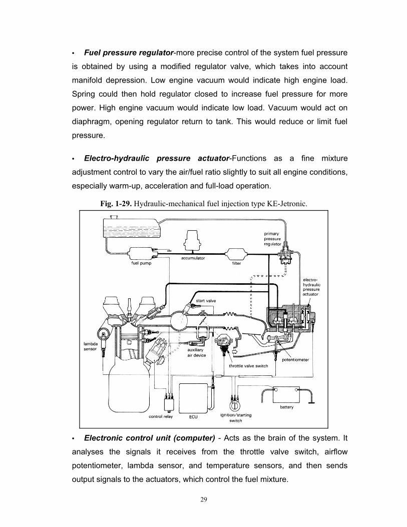
• Fuel pressure regulator-more precise control of the system fuel pressure
is obtained by using a modified regulator valve, which takes into account
manifold depression. Low engine vacuum would indicate high engine load.
Spring could then hold regulator closed to increase fuel pressure for more
power. High engine vacuum would indicate low load. Vacuum would act on
diaphragm, opening regulator return to tank. This would reduce or limit fuel
pressure.
• Electro-hydraulic pressure actuator-Functions as a fine mixture
adjustment control to vary the air/fuel ratio slightly to suit all engine conditions,
especially warm-up, acceleration and full-load operation.
Fig. 1-29. Hydraulic-mechanical fuel injection type KE-Jetronic.
• Electronic control unit (computer) - Acts as the brain of the system. It
analyses the signals it receives from the throttle valve switch, airflow
potentiometer, lambda sensor, and temperature sensors, and then sends
output signals to the actuators, which control the fuel mixture.
29

HYDRAULIC-MECHANICAL FUEL INJECTION SYSTEM PROBLEMS
Poor Engine Performance
• Clogged or dirty air filter.
• Clogged fuel lines or fuel filter.
• Defective fuel pump.
• Dirty injectors.
• Defective injectors.
• Clogged exhaust system.
• Defective fuel distributor.
• Defective airflow sensor.
• Defective computer in KE-jetronic system.
• Defective sensors in KE- jetronic system.
• Defective electro-hydraulic pressure actuator in KE-jetronic system.
• Air leak at intake manifold.
• Leaking vacuum lines.
• Defective fuel pressure regulator.
Hard Starting
• Defective thermo-time switch.
• Defective cold-start injector.
• Defective warm-up regulator in K-jetronic system.
• Defective idle air bypass valve.
• Defective fuel pump.
• Defective fuel pressure regulator.
• Defective fuel accumulator.
• Dirty injectors.
• Defective injectors.
• Air in the fuel line.
• Defective fuel distributor.
• Defective electro-hydraulic pressure actuator in KE-jetronic system.
30

• Defective engine coolant temperature sensor in KE-jetronic system.
Excessive Fuel Consumption
• Incorrect adjustment of idle mixture screw.
• Defective fuel pressure regulator.
• Defective thermo-time switch.
• Defective cold-start injector.
• Defective warm-up regulator in K-jetronic system.
• Defective idle air bypass valve.
• Defective lambda sensor in KE-jetronic system.
• Defective fuel distributor.
• Defective electro-hydraulic pressure actuator in KE-jetronic system.
• Defective injectors.
• Dirty injectors.
• Fuel leaking.
• Defective engine coolant temperature sensor in KE-jetronic system.
MULTI-POINT ELECTRONIC FUEL INJECTION SYSTEMMulti-point electronic fuel injection system is indirect injection. This means that
the fuel is sprayed into the engine intake manifold ports.
In multi-point electronic fuel injection system uses engine sensors and a
computer to control the opening and closing of injection valve. There are
generally as many injectors as there are cylinders. Most multi-point electronic
fuel injection systems are intermittent. This means that the injectors are not
energized at the same time. There are different types of intermittent injection.
The injectors can be turned ON and OFF in pairs or in a specific sequence that is
related to valve timing.
There are four common types of multi-point electronic fuel injection systems:
L- Jetronic, L3- Jetronic, LH - Jetronic, and Motronic systems.
Generally, multi-point electronic fuel injection system can be divided into four
subsystems:
• Fuel delivery system.
• Air induction system.
31

• Sensor system.
• Computer control system.
These four subsystems are illustrated in Fig. 1-30.
Fuel delivery system
The fuel delivery system of multi-point EFI system includes an electric fuel pump,
fuel filter, fuel pressure regulator, injector valves, and connecting lines and
hoses. See Fig. 1-31.
The electric fuel pump draws gasoline out of the tank and forces it into the fuel
pressure regulator.
The fuel pressure regulator controls the amount of pressure entering the
injector valves. See Fig. 1-32. When engine vacuum is low, this would indicate
Fig. 1-30. Multi-point electronic fuel injection.
32
Idle air bypass valve
Connected to intake manifold vacuum
4. computer control system
2. Air induction system
1. Fuel delivery system
Fuel
Crankshaftposition sensor
3. Sensor system
Distributor RPM sensor

Fig. 1-31. Fuel delivery system.
high engine load. Spring could then hold regulator return closed to increase fuel
pressure for more power. When engine vacuum is high, this would indicate low
load. Vacuum would act on diaphragm, opening regulator return to tank and
reduce fuel pressure. This maintains a preset amount of fuel pressure for injector
valve operation.
Fig. 1-32. Fuel pressure regulator operation.
A fuel injector for multi-point EFI system is simply a coil or solenoid operated
fuel valve that sprays and atomizes the fuel. See Fig. 1-33. When not energized,
spring pressure makes the injector remain closed, keeping fuel from entering the
33

Fig. 1-33. Multi-point EFI injector operation.
engine. When current flows from the computer through the injector coil, the
magnetic field attracts the injector armature. The injector valve opens. Fuel then
squirts into intake manifold under pressure.
Air induction system
An air induction system for multi-point EFI typically consists of an air filter, throttle
valves, idle air bypass valve, and connecting ducts.
34

The throttle valve regulators how much airflows in the engine. In turn, it controls
engine power out put. Like a carburetor throttle valve, it is connected to the
driver’s gas pedal. When the pedal is depressed, the throttle valve swings open
to allow air to rush into the engine.
An idle air bypass valve, also called idle speed actuator, is used in multi-point
EFI to help control engine idle speed. It is solenoid operated air bypass valve.
The system computer opens and closes the idle air bypass valve. When open,
the idle air bypass valve allows more air to enter the intake manifold. This tends
to increase idle rpm. When closed, the valve decreases bypass air and idle
speed. See Fig. 1-34.
The computer decides to increase or decrease the idle rpm after receiving input
signals from the sensors. This keeps the idle speed at a constant rpm, regardless
of the load placed on the engine while idling.
Fig. 1-34. Idle air bypass valve or idle speed actuator.
Sensor system
The multi-point EFI sensors system monitors engine-operating conditions and
reports this information to the computer. A typical EFI sensors system consists of
an exhaust gas or oxygen sensor, intake manifold pressure (vacuum) sensor,
throttle position sensor, engine coolant temperature sensor, airflow sensor, inlet
air temperature sensor, crankshaft position sensor or distributor rpm sensor, and
other sensors.
35

Engine sensors are an electrical device that changes circuit resistance or voltage
with a change in a condition (temperature, pressure, position of parts, etc.).
Computer control system
The computer control system uses electrical data from the sensors to control the
operation of the fuel injectors. A wiring harness connects the engine sensors to
the input of the computer. Another wiring harness connects the output of the
computer to the fuel injectors.
The computer, also called an ELECTRONIC CONTROL UNIT (ECU), is the
‘’brain’’ of the electronic fuel injection system. The ECU uses sensor output to
calculate when and how long to open the fuel injectors.
To open an injector, the computer connects the injector coil to battery voltage. To
close the injector, the computer opens the circuit between the battery and the
injector coil.
ENGINE SENSORS
Typical sensors for multi-point EFI system include:
• An exhaust gas or oxygen sensor (Lambda sensor).
• An intake manifold pressure sensor.
• A throttle position sensor.
• An engine coolant temperature sensor.
• An airflow sensor.
• An inlet air temperature sensor.
• A crankshaft position sensor.
• A distributor rpm sensor.
Exhaust gas or oxygen sensor (Lambda sensor)
36
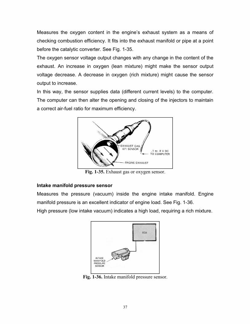
Measures the oxygen content in the engine’s exhaust system as a means of
checking combustion efficiency. It fits into the exhaust manifold or pipe at a point
before the catalytic converter. See Fig. 1-35.
The oxygen sensor voltage output changes with any change in the content of the
exhaust. An increase in oxygen (lean mixture) might make the sensor output
voltage decrease. A decrease in oxygen (rich mixture) might cause the sensor
output to increase.
In this way, the sensor supplies data (different current levels) to the computer.
The computer can then alter the opening and closing of the injectors to maintain
a correct air-fuel ratio for maximum efficiency.
Fig. 1-35. Exhaust gas or oxygen sensor.
Intake manifold pressure sensor
Measures the pressure (vacuum) inside the engine intake manifold. Engine
manifold pressure is an excellent indicator of engine load. See Fig. 1-36.
High pressure (low intake vacuum) indicates a high load, requiring a rich mixture.
Fig. 1-36. Intake manifold pressure sensor.
37
Low manifold pressure (high intake vacuum) indicates very little load, requiring a
leaner mixture. The manifold pressure sensor changes resistance with changes
in engine load. This data is used by computer to alter the fuel mixture.
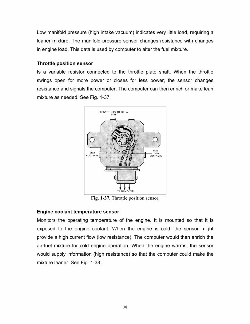
Throttle position sensor
Is a variable resistor connected to the throttle plate shaft. When the throttle
swings open for more power or closes for less power, the sensor changes
resistance and signals the computer. The computer can then enrich or make lean
mixture as needed. See Fig. 1-37.
Fig. 1-37. Throttle position sensor.
Engine coolant temperature sensor
Monitors the operating temperature of the engine. It is mounted so that it is
exposed to the engine coolant. When the engine is cold, the sensor might
provide a high current flow (low resistance). The computer would then enrich the
air-fuel mixture for cold engine operation. When the engine warms, the sensor
would supply information (high resistance) so that the computer could make the
mixture leaner. See Fig. 1-38.
38

Fig. 1-38. Engine coolant temperature sensor.
Airflow sensor
Is used in many EFI systems to measure the amount of outside air entering the
engine. This helps the computer to determine how much fuel is needed.
The airflow sensor is usually an air flap that operates a variable resistor or hot-
wire air-mass meter.
An airflow sensor, air flap types, is a flap-operated variable resistor. See
Fig.1-39. Airflow through the sensor causes an air flap to swing to one side.
Since the air flap is connected to a variable resistor, the amount of airflow into
the engine is converted into an electrical signal for the computer. The computer
can then enrich or make lean mixture as needed.
Fig. 1-39. Airflow sensor, air flap types.
39

An airflow sensor, hot-wire air-mass meter types, has a hot wire made of
platinum element which is heated by an electric current sufficient to maintain it at
a constant temperature. See Fig. 1-40. When the airflow is increased, the cooling
action is greater, so a large current has to be passed through the wire to prevent
a drop in its temperature. The voltage required to provide this current gives an
indication of the inducted air mass. This voltage is signaled to ECU to enable the
ECU to compute initially the basic quantity of fuel. The quantity is then slightly
altered to take account of the signals it receives from other engine sensors.
Fig. 1-40. Airflow sensor, hot-wire air-mass meter types.
Inlet air temperature sensor
Measures the temperature of the air entering the engine. See Fig. 1-41.
Cold air is more dense than warm air, requiring a little more fuel. Warm air is not
as dense as cold air, requiring a little less fuel. The air temperature sensor helps
the computer compensate for changes in outside air temperature and maintain
an almost perfect air-fuel mixture ratio.
40
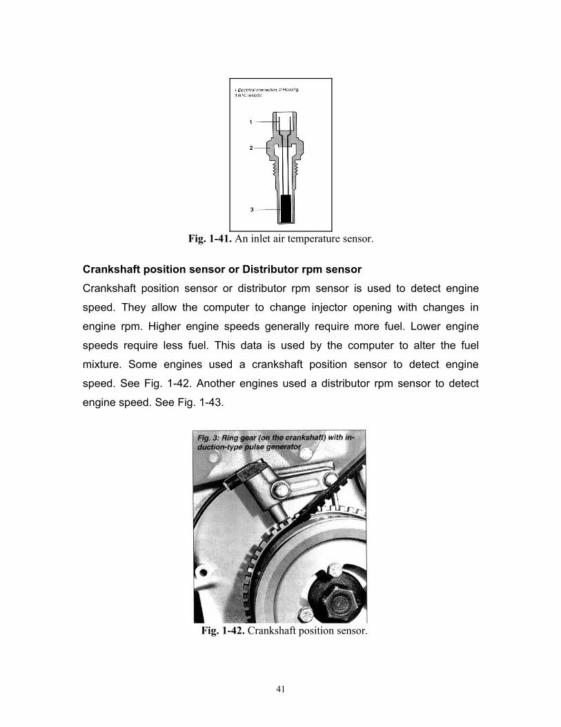
Fig. 1-41. An inlet air temperature sensor.
Crankshaft position sensor or Distributor rpm sensor
Crankshaft position sensor or distributor rpm sensor is used to detect engine
speed. They allow the computer to change injector opening with changes in
engine rpm. Higher engine speeds generally require more fuel. Lower engine
speeds require less fuel. This data is used by the computer to alter the fuel
mixture. Some engines used a crankshaft position sensor to detect engine
speed. See Fig. 1-42. Another engines used a distributor rpm sensor to detect
engine speed. See Fig. 1-43.
Fig. 1-42. Crankshaft position sensor.
41

Fig. 1-43. Distributor rpm sensor.
INJECTOR PULSE WIDTH
The injector pulse width indicates the amount of time each injector is energized
and kept open. The computer controls the injector pulse width.
Under full acceleration, the computer will sense a wide-open throttle, high intake
manifold pressure, and high inlet airflow. The computer would then increase
injector pulse width to enrich the mixture for more power. See Fig. 1-44.
Fig. 1-44. Injector pulse width.
42

Under low load conditions, the computer will shorten the injector pulse width.
With the injectors being closed a large percentage of time, the air-fuel mixture will
be leaner for better fuel economy.
L-JETRONIC FUEL INJECTION SYSTEM
The L-Jetronic is an electronically controlled fuel injection system, which injects
fuel intermittently into the intake manifold ports.
The L-jetronic system uses airflow sensor, air flap types, which is connected to
variable resistor, to measure the amount of outside air entering the engine.
The L-jetronic system, Fig. 1-45, typically consists of:
• Fuel delivery system (electric fuel pump, fuel filter, fuel pressure regulator,
fuel injectors, cold start injector, fuel accumulator, and connecting lines and
hoses).
• Air induction system (air filter, throttle valves, idle air bypass valve, and
connecting ducts).
• Sensor system (airflow sensor, throttle position sensor, engine coolant
temperature sensor, inlet air temperature sensor, lambda sensor, and
distributor rpm sensor or crankshaft position sensor).
• Computer control system.
Operation
When the ignition switch is turned on and the engine is stationary, battery voltage
powers the ECU and the electric fuel pump through the relay. See Fig. 1-45. For
two seconds, the electric fuel pump draws the fuel from fuel tank at pressure of
approximately 2.5 bar (36 psi) through a filter into the fuel rail. From the fuel rail,
fuel lines diverge to the injection valves (injectors) and to the cold start injector,
for initial engine start-up. After two seconds, the relay will cut off the circuit
between the battery and the electric fuel pump.
When the ignition switch is rotated to the start position and the engine is running,
the relay connects the circuit between the battery and the electric fuel pump.
With the engine running, the time during which the fuel injection valves remain
open is controlled by the signal from the ECU, which computes this time based
43

on the signals received from the engine mounted sensors (airflow sensor, inlet air
temperature sensor, distributor rpm sensor or crankshaft position sensor, engine
coolant temperature sensor, throttle position sensor, and lambda sensor).
Fig. 1-45. L-Jetronic fuel injection system.
44
1.fuel tank, 2.Electric fuel pump, 3.Fuel filter, 4.Distributor pipe, 5.Fuel pressure regulator, 6.Control unit (computer), 7.Injection valve (injector), 8.Cold start injector, 9.idle-speed adjusting screw, 10.Throttle position sensor, 11.Throttle valve, 12.Airflow, 13.Relay combination, 14.lambda sensor, 15.Engine temperature sensor, 16.Thermo-time switch, 17.Ignition distributor, 18.Idle air bypass valve, 19.Idle-mixture adjusting screw, 20.Battery, 21.Ignition-starter switch.

L3-JETRONIC FUEL INJECTION SYSTEM
The L3-Jetronic fuel injection system has the same components of the L-Jetronic
fuel injection system but there is some difference between them.
The L3-jetronic differs from L-Jetronic in respect of the following details, see Fig.
1-46 and Fig. 1-47:
• The control unit, which is suitable for installation in the engine
compartment, is attached to the airflow sensor and thus no longer requires
space in the passenger compartment.
• The combined unit of control unit and airflow sensor with internal
connections simplifies the cable harness and reduces installation expense.
• The use of digital techniques permits new function with improved
adaptation capabilities to be implemented as compared with the previous
analog techniques used.
Fig. 1-46. L3-Jetronic fuel injection system.
45

Fig.1-47. Integration of ECU and airflow sensor of the L3-Jetronic system.
LH-JETRONIC FUEL INJECTION SYSTEM
The LH-Jetronic is closely related to the L-Jetronic. The difference lies in the hot-
wire air-mass meter which measures the air mass inducted by the engine instead
of air flap types. See Fig. 1-48.
Fig. 1-48. LH-Jetronic fuel injection system.
MOTRONIC FUEL INJECTION SYSTEM
46

The Motronic fuel injection system uses an L-Jetronic system or LH-Jetronic
system coupled with an electronic ignition system, with both systems being
controlled by a common digital microcomputer. The same sensors can be used
for both the fuel injection and ignition; thus more is achieved at a lower cost than
with two separate systems. See Fig. 1-49.
Fig. 1-49. Motronic fuel injection system.
MULTI-POINT ELECTRONIC FUEL INJECTION SYSTEM PROBLEMS
47

Poor Engine Performance
• Air leak at intake manifold.
• Clogged or dirty air filter.
• Clogged fuel lines or fuel filter.
• Defective fuel pump.
• Dirty injectors.
• Defective injectors.
• Clogged exhaust system.
• Leaking vacuum lines.
• Defective sensors.
• Defective fuel pressure regulator.
• Defective computer.
• Defective idle air bypass valve.
Hard Starting
• Defective thermo-time switch.
• Defective cold-start injector.
• Defective idle air bypass valve.
• Defective fuel pressure regulator.
• Defective fuel pump.
• Dirty injectors.
• Defective injectors.
• Air in the fuel lines.
• Defective engine coolant temperature sensor.
• Defective inlet air temperature sensor.
• Defective fuel accumulator.
Excessive Fuel Consumption
• Defective fuel pressure regulator.
• Defective thermo-time switch.
• Defective cold-start injector.
• Defective lambda sensor.
48
• Defective idle air bypass valve.
• Defective injectors.
• Dirty injectors.
• Defective engine coolant temperature sensor.
• Defective inlet air temperature sensor.
• Fuel leaking.
SINGLE-POINT ELECTRONIC FUEL INJECTION SYSTEM
Single-point electronic fuel injection system, is indirect injection system. This
means that the fuel is sprayed into the engine intake manifold ports.
Single-point electronic fuel injection system, has the injector nozzles in a throttle
body assembly on top of the engine. Fuel is sprayed into an intake manifold and
then delivered to the cylinders.
The injector is pulsed on and off so fast that it sprays a steady stream of fuel into
an intake manifold.
There are three common types of single-point electronic fuel injection systems:
THROTTLE BODY INJECTION (TBI) SYSTEM, MONO-JETRONIC SYSTEM,
and MONO-MOTRONIC SYSTEM.
THROTTLE BODY INJECTION SYSTEM (TBI system of General
Motors)
The TBI system, Fig. 1-50, typically consists of:
• Throttle body housing.
• Fuel injectors.
• Fuel pressure regulator.
• Throttle plates.
• Idle air control valve.
• Sensor system.
• Computer control system.
49

Operation
When the ignition switch is turned on and the engine is stationary, battery voltage
powers the ECU and the electric fuel pump through the relay. See Fig. 1-50. For
two seconds, the electric fuel pump draws the fuel from fuel tank at pressure of
approximately 2.5 bar (36 psi) through a filter into the fuel injector, for initial
engine start-up. After two seconds, the relay will cut off the circuit between the
battery and the electric fuel pump.
When the ignition switch is rotated to the start position and the engine is running,
the relay connects the circuit between the battery and the electric fuel pump.
With the engine running, the time during which the fuel injection valves remain
open is controlled by the signal from the ECU, which computes this time based
on the signals received from the engine mounted sensors (airflow sensor, inlet air
temperature sensor, distributor rpm sensor or crankshaft position sensor, engine
coolant temperature sensor, throttle position sensor, and lambda sensor).
Fig. 1-50. Throttle body injection system (TBI).
Throttle body housing
50
Crankshaft position sensor
Airflow sensor
Oxygen sensor
Intake manifold pressure sensor
Inlet air temperature sensor
Coolant temperature sensor
Throttle position sensor
Analyzeneeds
ControlInjectorpulses
Computer

It is a metal casting that holds injectors, fuel pressure regulator, throttle valves,
and other parts. See Fig. 1-51.
The TBI throttle body, like a carburetor body, bolts to the pad on the intake
manifold. Throttle plates are mounted in the lower section of the throttle body. A
linkage mechanism or cable connects the throttle plates with the driver’s gas
pedal. An inlet fuel line connects to one fitting on the throttle body. An outlet
return line to the tank connects to another fitting on the throttle body.
Throttle body injector
It is a solenoid operated fuel valves mounted in upper section of throttle body
assembly. See Fig. 1-52.
A throttle body injector consists of an electric solenoid coil, armature or plunger,
needle valve, needle seat, and injector spring.
Wires from the computer (electronic control unit) connect to the terminals on the
injectors. When the computer energizes the injectors, a magnetic field is
produced in the injector coil. The magnetic field pulls the plunger and valves up
to open the injector. Fuel can then squirt through the injector nozzle and into the
engine.
Fig. 1-51. The TBI housing bolts to the pad on the intake manifold.
51

Fig. 1-52. Throttle body injector.
Throttle body fuel pressure regulator
It is a spring-loaded bypass valve that maintains constant fuel pressure at
injectors. The throttle body fuel pressure regulator consists of a fuel valve,
diaphragm, and spring. See Fig. 1-53. When fuel pressure is low (initial engine
starting), the spring holds the fuel valve closed. This causes pressure to build as
fuel flows into the regulator from the electric fuel pump.
When a preset pressure is reached, pressure acts on the diaphragm. The
diaphragm compresses the spring and opens the fuel valve. Fuel can then flow
back to the fuel tank. This limits the maximum fuel pressure at the injectors.
Idle air control valve
An idle air control valve is used in a TBI to help control engine idle speed. It is a
solenoid operated air bypass valve. See Fig. 1-53. The system computer
normally opens and closes the idle air control valve.
When open, the idle air control valve allows more air to enter the intake manifold.
This tends to increase idle rpm. When closed, the valve decreases bypass air
and idle speed. The valve can be used to control both slow and fast idle speeds.
52

Throttle plate
It is butterfly valves that control airflow through throttle body. See Fig. 1-53.
Fig. 1-53. Basic parts of TBI.
Sensor system
Monitors engine operating conditions and reports this information to the computer
(crankshaft position sensor, airflow sensor, throttle position sensor, engine
coolant temperature sensor, inlet air temperature sensor, exhaust gas or oxygen
sensor, intake manifold pressure sensor, and distributor rpm sensor or crankshaft
position sensor).
Computer control system
The computer control system uses electrical data from the sensors to control the
operation of the fuel injectors. A wiring harness connects the engine sensors to
the input of the computer. Another wiring harness connects the output of the
computer to the fuel injectors.
MONO-JETRONIC FUEL INJECTION SYSTEM (Bosch Company)
Mono-Jetronic is an electronically controlled, single-point injection system for 4
cylinder engines. Mono-jetronic fuel injection system has the same components
of throttle body injection system (TBI), but the difference lies in the control of idle
speed.
53

In Mono-Jetronic fuel injection system, the position of throttle valve actuator (idle
speed switch) is closed to the throttle valve lever. See Fig. 1-54.
When the throttle valve actuator (idle speed switch) pushing the throttle valve
lever, this tends to increase idle speed of the engine.
Fig. 1-54. Mono-Jetronic fuel injection system.
54

MONO - MOTRONIC FUEL INJECTION SYSTEM (Bosch Company)
The Mono-Motronic fuel injection system has the same components of the Mono-
Jetronic fuel injection system but there is some difference between them.
Mono-Motronic fuel injection system coupled with an electronic ignition system,
with both systems being controlled by a common digital microcomputer. The
same sensors can be used for both the fuel injection and ignition; thus more is
achieved at a lower cost than with two separate systems. See Fig. 1-55.
Fig. 1-55. Mono-Motronic fuel injection system.
SINGLE-POINT ELECTRONIC FUEL INJECTION SYSTEM PROBLEMS
55

Poor Engine Performance
• Air leak at intake manifold.
• Clogged or dirty air filter.
• Clogged fuel lines or fuel filter.
• Defective fuel pump.
• Dirty injectors.
• Defective injectors.
• Clogged exhaust system.
• Leaking vacuum lines.
• Defective sensors.
• Defective computer.
• Defective throttle valve actuator (idle speed switch) in mono-jetronic fuel
injection system.
• Defective idle air control valve in throttle body injection system (TBI).
• Defective fuel pressure regulator.
Hard Starting
• Defective throttle valve actuator (idle speed switch) in mono-jetronic fuel
injection system.
• Defective idle air control valve in throttle body injection system (TBI).
• Defective fuel pressure regulator.
• Defective fuel pump.
• Dirty injectors.
• Defective injectors.
• Air in the fuel lines.
• Defective engine coolant temperature sensor.
• Defective inlet air temperature sensor.
• Defective fuel accumulator in mono-jetronic fuel injection system.
56

Excessive Fuel Consumption
• Defective fuel pressure regulator.
• Defective lambda sensor.
• Defective throttle valve actuator (idle speed switch) in mono-jetronic fuel
injection system.
• Defective idle air control valve in throttle body injection system (TBI).
• Defective injectors.
• Dirty injectors.
• Defective engine coolant temperature sensor.
• Defective inlet air temperature sensor.
• Fuel leaking.
57
Related Documents