UNCLASSIFIED AD NUMBER CLASSIFICATION CHANGES TO: FROM: LIMITATION CHANGES TO: FROM: AUTHORITY THIS PAGE IS UNCLASSIFIED ADA800689 unclassified confidential Approved for public release; distribution is unlimited. Distribution authorized to DoD only; Administrative/Operational Use; 07 MAY 1947. Other requests shall be referred to National Aeronautics and Space Administration, Washington, DC. Pre-dates formal DoD distribution statements. Treat as DoD only. NASA TR Server website; NASA TR Server website

Welcome message from author
This document is posted to help you gain knowledge. Please leave a comment to let me know what you think about it! Share it to your friends and learn new things together.
Transcript
UNCLASSIFIED
AD NUMBER
CLASSIFICATION CHANGESTO:FROM:
LIMITATION CHANGESTO:
FROM:
AUTHORITY
THIS PAGE IS UNCLASSIFIED
ADA800689
unclassified
confidential
Approved for public release; distribution isunlimited.
Distribution authorized to DoD only;Administrative/Operational Use; 07 MAY 1947.Other requests shall be referred to NationalAeronautics and Space Administration,Washington, DC. Pre-dates formal DoDdistribution statements. Treat as DoD only.
NASA TR Server website; NASA TR Server website

Reproduction Quality Notice
This document is part of the Air Technical Index [ATI] collection. The ATI collection is over 50 years old and was imaged from roll film. The collection has deteriorated over time and is in poor condition. DTIC has reproduced the best available copy utilizing the most current imaging technology. ATI documents that are partially legible have been included in the DTIC collection due to their historical value.
If you are dissatisfied with this document, please feel free to contact our Directorate of User Services at [703] 767-9066/9068 or DSN 427-9066/9068.
Do Not Return This Document To DTIC
Reproduced by
AIR DOCUMENTS DIVISION
• Jijii!
I
HEADQUARTERS AIR MATERIEL COMMAND
WRIGHT FIELD, DAYTON, OHIO
WH I ^—*— ••'! >ri*^^
5^ USGOVERNMENT
IS ABSOLVED
FROM ANY LITIGATION WHICH MAY " 1
ENSUE FROM THE CONTRACTORS IN -
FRINGING ON THE FOREIGN PATENT
RIGHTS WHICH MAY BE INVOLVED.
WRIGHT FIELD. DAYTON, OHIO


u
-sasw*'- *
• ''SS.-
{•
CONFiOeUTlAL
^ ,:..>--•
.t+ä^ftä,,^ ...-.Vi.ljgji, ^.
-t- --wSE...!
*•
^../.I'.J,-. I v4*!K^..'l :
•^jf*l*
•»*i..
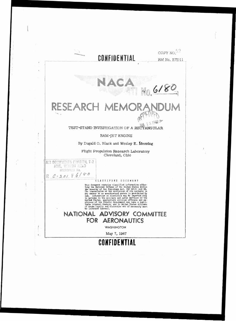
CONFIDENTIAL COPY NO.'
RM Nc. E7D11
RESEARCH MEMOR^DUM
TEST-STAND INVESTIGATION OF A RECTANGULAR
RAM-JET ENGINE
By Dugald O. Black and Wesley E. Jdessing
Flight Propulsion Research Laboratory Cleveland, Ohio
CLASSIFIED DOCUMENT
This document contains classified information affoo- ting the National Defense of the United States within the meaning of the Espionage Act, USC 50:31 and 32. Its transmission or the revelation of its contents in any manner to an unauthorised person is prohibited by las. Information so classified may be Imparted only to persons in the military and naval Services of the United States, appropriate civilian officers and em- ployees of the Federal Government «ho have a legit- imate interest therein, and to United States citiiens of known loyalty and discretion «ho of necessity must be informed thereof.
NATIONAL ADVISORY COMMITTEE FOR AERONAUTICS
WASHINGTON
May 7, 1947
CONFIDENTIAL
f
NACA BM No. E7D11 CONFIDENTIAL
NATIONAL ADVISORY COMMITTEE FOB AERONAUTICS
RESEARCH MEMORANDUM
TEST-STAND INVESTIGATION OF A RECTANGULAR
RAM-JET ENGINE
By Dugald 0. Black and Wesley E. Mossing
SUMMARY
A test-stand investigation has been conducted on a rectangular ram-Jet engine designed for installation in an aircraft wing. The combustion efficiency was determined for a fuel-air-ratio range of 0.025 to 0.083 and for a range of combustion-chamber inlet velocities from 61 to 124 feet per second.
The engine operated without excessive engine noise or vibration over the entire raage of operating conditions. The combustion efficiency waB approximately 80 percsnt at fuel-air ratios from 0.060 to 0.068 over a ra»;;e of combustion-chamber inlet velocities from 64 to 83 feet per second. In general, a change in fuel-air ratio above or below stoioniums trie mixture resulted in a decrease in combustion efficiency. The only noticeable effect of combustion- chamber inlet velocity on combustion efficiency occurred at fuel- air ratios lees than 0.043, at which condition an increase in combustion-chamber inlet velocity resulted in an increase In combustion efficiency for a given fuel-air ratio. Orsat analysis of the exhaust gases for measurod fuel-air ratios of 0.065 and 0.042 indicated fairly uniform fuel-air-ratio distribution across the exit of the engine.
I
INTRODUCTION
As part of a research program on ram-Jet engines, test-stand and flight investigations at subsonic velocities are being conducted at the NACA Cleveland laboratory to determine the performance and operational characteristics of a rectangular ram-Jet engine designed for installation in an aircraft wing.
During the test-stand Investigation reported herein, combustion efficiency was determined for fuel-air-ratioe from 0.025 to 0.083 and combustion-chamber inlet velocities from 61 to 124 feet per
v.J:
CONriDENTIAL
J

CONFIDENTIAL NACA EM No. E7D11
second. Exhaust-pas analyses were made at various stations across the exit of tue ram-Jet engine to dotermlne the fuel-air-ratio distribution. Because of the comparatively low inlet-air velocities available, only a limited amount of information on blow-out and Ignition lünits were obtained. A flicht investigation on a rectan- gular ram-Jet engine Installed in a short-span wing mounted beneath the fuselage of a twin-engine fighter-type airplane will extend the investigation to higher combugtion-chamber velocities and altitudes from sea level to 30,000 feet.
APPARATUS AMD PROCEDURE
•V
1
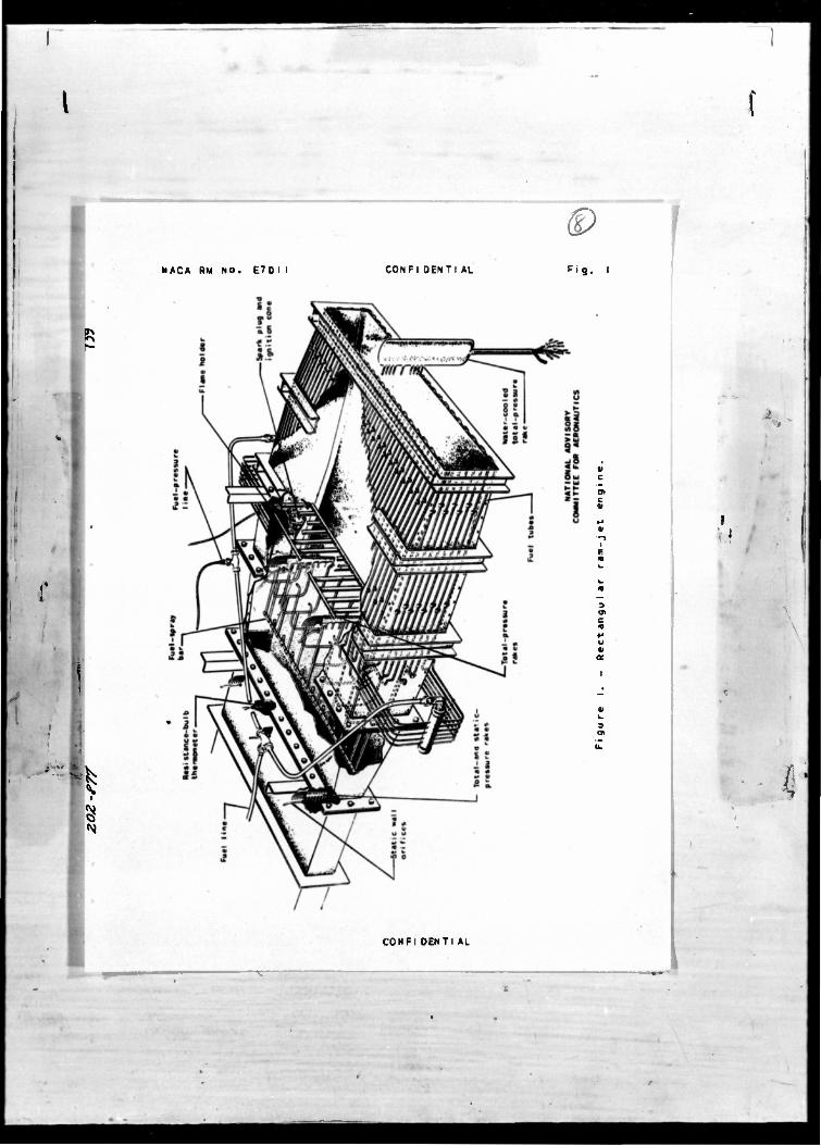
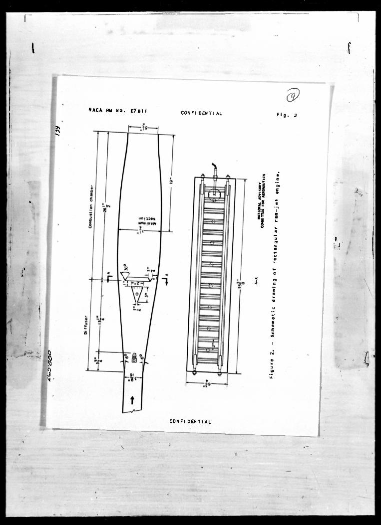
The rectangular ram-Jet engine (figs. 1 and 2) consists of an inlet diffuser, fuel-spray bor, spart plug and ignition cone, flame holder, and combustion chamber. The diffaser inlet is of a rectan- gular cross section with a 12° total diffuser angle between the top and the bottom walls. One of the parallel side walls contained a transparent section upstream of the flacie holder, which permitted visual observation of the fuel spray and combustion. The combustion chamber was cooled by circulating the fuel through l/4-inch copper tubing clamped to the wall of the combustion chamber. In addition to cooling the combustion chamber, this system preheated the fuel. The fuel pressure loss in the l/4-inch tubing was kept low by using a number of separate flow paths Instead of one continuous path.
The fuel-spray bar consisted of eight fixed-area spray nozzles evenly spaced along the horizontal center line of the diffuser. Each nozzle had a rated flow of 40 gallons of fuel per hour at a fuel pressure of 100 pounds per square Inch and discharged downstream in a 60" cone. The flame holder, consisting of horizontal and vertical T-shaped gutters, was fabricated from 0.064-inch Inconel. The measured nressure-dror) coefficient without combustion =£ for
this flame holder was 1.40, (where ap, Treasure drop in In. water across flame holder; q, impact pressure in in. water directly In front of flame holder). Burning was initiated by a spark plug installed in an Ignition cone mounted in front of the flame holder. No auxiliary fuel was introduced in the ignition cone.
Air was supplied to the engine by a 500-horsepower, variable- speed, axial-flow blower capable of supplying a pressure rise of 45 inches of water. The engine exhausted to ths atmosphere. The fuel used for these tests was AN-F-22 (62 octane).
CONFIDENTIAL
k'

I HACA Hl Ho. E7D11 COHFIDEHTIAI,
Data were obtained over a range of fuel-air ratios from 0.025 to 0.063 and combustlon-obamber inlot velocities (at the flaue bolder) from 61 to 124 feet per second.
Engine air flow was calculated from the total and the static pressures measured at the diffuser inlet with three rates and six static wall orifices and from the inlet-air temperatures indicated by a resistance-bulb thermometer. The amblont-air pressure was measured by a rocording barometer. The total pressures of the exhaust gases were measured by means of a water-cooled Inconel rake. Static-pressure surveys made at the exit of the engine indicated that the static pressure was equal to the ambient pres- sure. Pressure data wore obtained simultaneously by photographing a multiple-tube manometer board. Fuel flow was measured with a rotamoter. Orsat analyses were made of the oxidized exhaust gases to determine the fuel-aJr ratio at various points across the exit of the ram-jet engine.
The exhaust-gas temperature cX the exit of the ram Jet was calculated fron the measured gas flow aiid pressure measurements at the exit of tho combustion chauler in accordance with the method outlined in refei.'enco 1. Tho combustion efficiency was determined in accordance with the following equation:
h
% %
f/a (h) 100 (1)
whciv
Ha
h
f/a
combustion efficiency, percent
enthalpy of air and fuel before combustion, Btu per pound of original air
enthalpy of burned gases at exit-gas temperature, Etu par pound of original air
lower heating value of fuel, 10,500, Btu per po-.ind
fuel-air ratio
V.I
For the purpose of these calculations, II- was assumed equal to the enthalpy of air at the exhaust-gas temperature plus the sum of the enthalpies of carbon dioxide and water that results from complete combustion minus the entlialpy of oxygen required for complete combustion. Enthalpy values were obtained from reference 2.
COHFUEWTIAL
tl
1 COHFTDJ'NTIAL MCA KM Nu. E7D11
Attempts were also made to determine the combustion efficiency by measuring the carbun-dioxide and oxygen content of the exhaust gases. The combustion efficiencies obtained by this method were considerably higher than the results obtained from the pressure and the gas-flow measurements. Calculations involving the heat-transfer process between the water-cooled sampling tube and the exhaust gases indicate that this discrepancy existed because the exhaust gases wore in the sampling tube an appreciable length of time before being cooled sufficiently to stop combustion.
HKSULTS AUS DISCUSSION
At the highest combustion-chamber inlet velocity attainable with the blower (200 ft/sec without combustion), ignition took place at a fuel-air ratio of approximately 0.020. The engine operated without excessive noise or vibration for the entire range of operating condi- tions and at no time did the flame advance upstream of the flame holder.
1
The exhaust flame consisted of a shorty steady blue flame extending approximately 1 foot beyond the exit of the engine for a fuel-air-ratio range of 0.045 to 0.065. As the fuel-air ratio was Increased above stolchlometric (0.067), the exhaust flora became longer and yellow duo to afterburning of the excess fuel. The horizontal gutters of the flame holder failed to hold the flame properly at fuel-air ratios from 0.055 to 0.045. Bolow a fuel-air ratio of 0.045, the flame was held sold; by the vortical gutters of tho flame holder and became increasingly irregular and unsteady with a decrease in fuel-air ratio until the lean blow-out limit was reached. The Irregular burning In tho combustion chamber Is believed to result from the inadequate penetration of the fuel particles into the air stream because of the low fuel pressures that exist at the low fuel-flow rates. This inadequate penetration of the fuel particles created zones of fuel- air mixtures sufficiently rich to maintain localized combustion. Because of this unstable condition, the exact fuel-air ratio at which blow-out occurred was difficult to measure.
During operation at fuel-air ratios of 0.060 and higher, short red streaks appeared on the wall of the combustion chamber directly behind each flame-holder support. These supports held the flame at the higher fuel-air ratios end caused combustion to occur near the wall.
COIPIDENTIAL
u
f
MCA KM No. S'/Cll CONFUTEHTIAL
The general effect of fuel-air ratio on combustion efficiency is shown in figure 3. The maximum combustion efficiency obtained TOB 84 percent at a fuel-a1r ratio of 0.063 and a combustion- chamber Inlet velocity of 83 feet per second. The average combustion efficiency was 80 percent at fuel-air ratios from 0.060 to 0.068 over a range of combustion-chamber inlet velocities from 64 to 83 feet per second. In general, a change In fuel-air ratio abovo or below stoi- chloaetrlc mixture (0.067) resulted in a decrease in combustion effi- ciency. The rapid decrease in combustion efficiency with decreasing fuol-air ratio between a fuel-air ratio of 0.0S5 and 0.045 was due in iXirt to the gradual blow-out of the flame at the horizontal gutters. The inlet-air temperature varied from SO0 to 130° F and the ambient- air pressure from 28.90 to 29.25 Inches of mercury. These small variations apparently had little effeot on combustion efficiency. Because of the fixed-area fuel nozzles the other variables such as fuel pressure and temperature were a function of fuel-air ratio and inlet-air velocity at the flame holder.
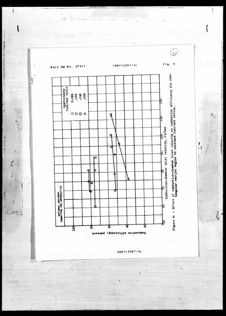
The effect of a variation in combustion-chamber inlet velocity on combustion efficiency for four constant fuel-air ratios is shown in figure 4. At fuel-air ratios of approximately 0.065 and 0.055, no noticeable change in combustion efficiency occurred for the variation in combustion-chamber inlet velocity. At fuel-air ratios of approximately 0.043 and 0.033, an Increase in combastion-chamber inlet velocity resulted in an increase in combustion efficiency.
t
1
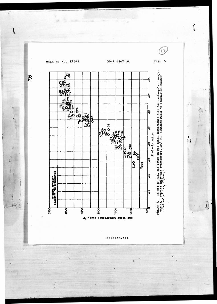
The effect of fuel-air ratio on gas total-temperature rise is presented in figure 5. A temperature rise of approximately 3000° F was obtained at stoichionotric fuel-air ratio. Slightly higher temperature rises were obtained at fuel-air ratios from 0.070 to 0.080.
Fuel-air-ratio distribution across the exit of the ram-Jet engine determined by oxidized exhaust-gas analyses is shown in figure 6 for calculated fuol-air ratios of 0.065 and 0.042. In general, the fuel-air ratio is slightly richer through the horizontal center line than near the walls of the chamber. The average fuel-air ratio obtained by Orsat analysis was in close agreement with the calculated fuel-air ratio.
CONFIDENTIAL
81
f
COHFUENTIAL NACA BM No. E7D11
SUMM\KY OF HESULTS
From a test-stand investigation of a rectangular ram-Jet engine over a ratine of fuel-air rati.oB from 0.u2L> tu 0.063 and combustion- chamber inlet velocities from 61 to 124 feet per second, the following roBults were obtained:
1. At the highest combueticr\-chamber inlet velocity attainable w'th the blower (200 ft/sec without combustion), ignition took place at a fuel-air ratio of approximately 0.020.
2. Tho engine operated without exceaslve noise or vibration for the entire range of operating conditions.
3. The combustion efficiency was approximately 80 percent at fnel-air ratios from 0.U60 to 0.068 over a range of combustion-chamber inlet velocities from 64 to 03 feet per second. In general, a change in fuel-air ratio above or belcw etoichioioetrtc mixture resulted in a decrease in combustion efficiency.
4. The only noticeable effect of combustion-chamber inlet velocity on combustion efficiency occ.irreu. at fuel-air ratios less than 0.043, at which condition an increase in combustion-chamber inlet velocity resulted in an increase in combustion efficiency for a given fuel-air ratio.
I I i
...» -.
Ü
COIIFIESHTIAL

NACA KM No. E7D11 CONFUENTIAL
5. Exhaust-gaa analysis indicated fairly uniform fuel-air-ratio distribution across the exit of the raia Jet for fuel-air ratios of 0.065 and 0.043.
Fliglit Propulsion Research. Laboi'ntory, National Advisory Committee for Aeronautics,
Cleveland, Ohio.
REFERENCES
1. Perchonok, Eugene, Wllcox, Frod A., and Sterbentz, William H.: Preliminary I»velo;.mont and Performance Investigation of a 20-Inch Steady-Flow Ham Jet. NACA ACE No. E6D0S, 1946.
2. Turner, L. Richard, mid Lord, Albert M.: Thermodynamic Cliarts for tiie Computation of Combuet?on and Mixture Temperatures at Constant Treasure. NACA TN No. 1066, 1946.
!
f-' k\
C0I1FUENTIAL
<p NACA RM NO. E7 DI I COM Fl OENTl AL Fl q. I
c
u
'-»
!
8-:
CONFl OENTl AL
f
I '.
i-"
9 MAC* Ml NO. E7DI I CONFIOENTIAL Fig. 2
i! 8* 3E
R
3
c
u a
O
en
I
I
1
I
CONFIOENTI AL

(9 ;
NACA KM NO. E7 0 I I CONFI DENTI AL Fig. 3
S °s U3
% B •
1 & t-
H«IO
*45 0> •
<-)Ou 0*O t~
8 ^O
M £ •
jf (0 <E
9 ft 6 lam •O
*
1.1 1 rjü 1
"ff? *f L—•• CSS c e
6
OB ro
rHH
^r •
•A D
SI — • > w « • «to. ow — Ul
|E
?! •
f-i
° • 1 1 I 1 1 7 •«
I f i J c
quasjod 'fouajouja uofjs-nqmoD
CONFI DENTI AL
a i.
3 •
fa •
" O
9 S
5« "H
a *•
"> o-fi
1° ? §§ H OTJ
•SB So
a, fa
i
i
(•
^
f
Q NACA RM NO. E7DM COMF1OENTIAL Fi9-
...
I v »
Ü ^usoaad *Äoudj3iJjs uonsnqnoo
COMF1 OENTI AL
® NACA RM NO. E7 DI I CONFI DENTI At Fig. 5
. ,*,
i! si
r 8
a *
I? oft
a
frlO
§ -or o
iü V •A cF
3 « t*TV
^ _£ 8
:j 3 C no o c "H «I 4J *« w u 3 t. a
V. o 4*
£
M
S
~ ». o 3
0 o • -• u a) o.
V • 0
* • a> o u toe i 1 «rl C I. . a» -I
> U .£ O
4i *~« V
f |gM3
£^ '*SJJ •on)s>isdiiie4-x«403 seo
i 1
8
CONFI0ENTIAL

<9 NAC» RM NO. E70I l CONFIDENTiAL Fig. 6
:s
V) o o a
»
|Wr
*
r
•»•
in M B §
N 10
§8
en
o rf in m <o o o
I , I ,1,1 X« to «L «o io > ID in o o o o
E o
I, I
in c- e- «o o o •
i I io o»
8 8 • • o
T-r
oo in o> o» Bio to m to
o o o o
J I T*T" H H e- t- o o
J I
en in o s
o
• rH
i 4) 00 io 01 to uo a • >0 <
u to
•0 41
* 9 38 3 L O 3
•H 10 It « o 41
6 « at k
o m tH
8£ ^^ O a
o-o
ai 3 3
SPS 2 uo . 4) • E.
« SO 00 «io fe° >o <
t
i.f S
s
ü 3
83 o o
2 o
10 10 o o
T 1 :sr?
to o o i i
t» <M «O ro O O
rH «0
o o o
J_
in en o o
o o o
^
01 <0 m •*
o o o
_i_ _i
to io m o o o
rH 10 •* 10 o o
J__l I to 10 o
u I
>o
«I MO o) 9 <u • >o 4
eg <«JI bo 4) •
<
ai
I
o +> •p ß « 01
*3 o
ll m w U cd
4) • e % • o
N rH •* <n O I • b
ss a)
h
4) 3 h
0«H
w C -I 4> 10 >»*>
rH 4>
»i aj to ;. U a) Or 1 *5 a) o a 4>
3fc
5° 01 .p
O •H «> Ji CO
52 •H O C a)
•P n to
•H c •o o O-P •H IS
a) to E I 10 u a
•H O a »H I J.
rH 0) 4) >
I I i
j'
CONFI OENTI AL


f CONFIDENTIAL TITLE: Test-stand Investigation of a Rectangular Ramjet Engine
AUTHORS): Black, O. O.; Messing, W. E. ORIGINATING AGENCY: National Advisory Committee (or Aeronautics, Washington, D. C.
'PUBLISHED BY: Same
ATI- 6180 BIVISION/:,
JQPng- OaiO. A6EMCV NO.
RM-E7D11 •-/;
FU3USHINO A6IMCV NO.
Mav '47 I Confd'l COUNTOT
U.S. Eng. FAQ8 IUUSTOATIOM1
13 I tables, dlagrs. graphs ABSTRACT:
Experiments are made at subsonic velocities to determine performance and operational characteristics of engine designed for installation in aircraft wing. Combustion efficiency and combust ion-chamber inlet velocities were determined. Engine operated without ex- cessive.noise or vibration. Change In fuel-air ratio mixture resulted in decreased com- bustion efficiency. At fuel-air ratio less than 0.043, increase in combustion-chamber velocity resulted in increase of combustion efficiency for given fuel-air ratio.
DISTRIBUTION: Request copies of this report only from Originating Agency DIVISION: Power Plants, Jet and Turbine (5)- SECTION: Testing (IT?
ATI SHEET NO.: C-5-17-5
SUBJECT HEADINGS: Engines, Ram jet - Testing (34065.8); Combustion chambers - Testing (23865); Combustion - Mixture effects (23630)
Air Document* Division, Intolligonco Department Air Matoriol Command
Alt! TECHNICAL INDEX
CONFIDENTIAL
Wright-Pottor>on Air For» Bato Dayton, Ohio
-I
» + FFRmiABV HMO

S*
30 fccrcrcjf (h-il^e*^

( CONFIDENTIAL TITLE: T«st-sUnd Investigation of a Rectangutar Ramjet Engine
AUTHORS): Btack, D. O.; Messing, w. E. ORIGINATING AGENCY: National Advisory Committee for Aeronauttcs, Washington, D. C. PUBLISHED BY: Same
OTO- 6180
none
rootmwia AOfMCr NO.
May '47 Confd't U.S, Eng. 13 iiunnunooo tables, dlagrpr graphs
ABSTRACT:
Experiments are made at subsonic vetocittes to determine performance and operational characteristics of engine designed for lnstaltatlon In aircraft wing. Combustion effictency and combustion-chamber Inlet vetoclties were determined. Engine operated without ex- cessive noise or vibration. Change In fuel-air ratio mixture resutted in decreased com- bustion efficiency. At fuet-alr ratto less titan 0.043, Increase In combustton-chamber veloctty resulted In Increase of combustion efftciency for gtven fuet-alr ratio.
DISTRIBUTION: Request copies of this report only from Originating Agency DIVISION: Power Plants, Jet and Turbine (5) SECTION: Testing (17)
ATI SHEET NO.: C-5-17-5
SUBJECT HEADINGS: Engines, Ram Jet - Testing (34065.8); Combustion chambers - Testing (23865); Combustion - Mixture effects (23630)
Air Document» Division, IrttotliQonco Dtportmant Air Moloriol Command
Ala TECHNICAL INDEX CONFIDENTIAL .
.Wright-Fattarton Air Fare« BOM
Dayton, Ohio
Related Documents