Series JA/JAH/JB/JS Floating Joint Series Cylinder supply pressure Applicable bore size (mm) Mounting Page 908 Standard Series JA Basic style Flange style Foot style 913 Heavy load Series JAH Basic style Flange style Foot style 916 For compact cylinders Series JB Basic style (Female thread) Stainless steel type Series JS Basic style 918 Hydraulic cylinder Pneumatic cylinder Hydraulic cylinder Pneumatic cylinder Pneumatic cylinder Hydraulic cylinder 6, 10, 15 20, 25, 30, 40, 50, 63 80, 100, 125, 140, 160 20, 25, 30, 40, 50, 63 80, 100, 125, 140, 160 40, 50, 63, 80, 100 12, 16, 20, 25, 32 40, 50, 63, 80, 100 10, 16, 20, 25, 32 40, 50, 63, 80, 100 20, 25, 32 40, 50, 63 0.7 MPa or less 1 MPa or less 3.5 MPa or less 7 MPa or less 1 MPa or less 1 MPa or less 3.5 MPa or less The floating joint can absorb any “off-centering” or “loss of parallel accuracy” between the cylinder and the driven body. Centering is unnecessary. A high level of machining accuracy is unnecessary. The installation time is dramatically reduced. It is compact and is suitable for high tensile stresses. Long service life (with dustproof cover) Rotating angle······±5° Spherical rotation Eccentric slide Operating range Center of sphere Operating range Axial center Series Variations 907 J Individual -X D- -X Technical data

Welcome message from author
This document is posted to help you gain knowledge. Please leave a comment to let me know what you think about it! Share it to your friends and learn new things together.
Transcript

Series JA/JAH/JB/JSFloating Joint
Series Cylinder supply pressure Applicable bore size (mm) Mounting Page
908
Standard Series JA Basic style
Flange styleFoot style
913
Heavy load Series JAH Basic style
Flange styleFoot style
916
For compact cylindersSeries JB
Basic style(Female thread)
Stainless steel typeSeries JS
Basic style 918
Hydraulic cylinder
Pneumatic cylinder
Hydraulic cylinder
Pneumatic cylinder
Pneumatic cylinder
Hydraulic cylinder
6, 10, 15
20, 25, 30, 40, 50, 6380, 100, 125, 140, 160
20, 25, 30, 40, 50, 6380, 100, 125, 140, 160
40, 50, 63, 80, 100
12, 16, 20, 25, 3240, 50, 63, 80, 100
10, 16, 20, 25, 3240, 50, 63, 80, 100
20, 25, 3240, 50, 63
0.7 MPa or less
1 MPa or less
3.5 MPa or less
7 MPa or less
1 MPa or less
1 MPa or less
3.5 MPa or less
The floating joint can absorb any “off-centering” or “loss of parallel accuracy” between the cylinder and the driven body.
Centering is unnecessary.
A high level of machining accuracy is unnecessary.
The installation time is dramatically reduced.
It is compact and is suitable for high tensile stresses.
Long service life (with dustproof cover)
Rotating angle······±5°
Spherical rotation
Eccentric slide
Operating range
Center of sphere
Ope
ratin
g ra
nge
Axial center
Series Variations
907
J�
Individual-X�
D-�
-X�
Technicaldata
P0907-P0920-E.qxd 08.10.3 2:14 PM Page 907

Precautions
Mounting
Warning
Maintenance
Warning
Series JA
Specifications
Basic style, Flange style, Foot styleMounting
Operating range
JA
3-0504-0705-0806-1008-12510-12514-15018-15022-15026-15030-15036-150
M3 x 0.5M4 x 0.7M5 x 0.8M6 x 1
M8 x 1.25M10 x 1.25M14 x 1.5M18 x 1.5M22 x 1.5M26 x 1.5M30 x 1.5M36 x 1.5
40F 14-150
610152030406380100140160
610
10, 1520
25, 3240
50, 6380100
125, 140160
Model/Specifications
Model
Standard/Thread nominal size
Option/Thread nominal size
JA6-3-050JA10-4-070JA15-5-080JA15-6-100JA�20-8-125JA�30-10-125JA�40-14-150JA�63-18-150JA�80-22-150JA�100-26-150JA�140-30-150JA�160-36-150
6
10
10, 15
15
20
25, 32
40
50, 63
80
100
125, 140
160
M3 x 0.5
M4 x 0.7
M5 x 0.8
M6 x 1
M8 x 1.25
M10 x 1.25
M14 x 1.5
M18 x 1.5
M22 x 1.5
M26 x 1.5
M30 x 1.5
M36 x 1.5
19
54
123
123
1100
2500
6000
11000
18000
28000
54000
71000
–
–
–
–
1100
2500
4400
11000
18000
28000
36000∗
55000∗
–
–
–
–
1000∗
2000∗
4400
9000∗
14000∗
22000∗
36000∗
55000∗
0.5
0.5
0.5
0.5
0.5
0.5
0.75
1
1.25
2
2.5
3
JA�20-8-100JA�25-10-150JA�32-10-100JA�40-12-125JA�40-12-150JA�40-12-175JA�50-16-150JA�63-16-200JA�80-20-250JA�100-24-300JA�100-27-150JA�125-27-200JA�160-33-200
20
25
32
32, 40
40
32, 40
50
50, 63
80
100
100
125
160
M8 x 1
M10 x 1.5
M10 x 1
M12 x 1.25
M12 x 1.5
M12 x 1.75
M16 x 1.5
M16 x 2
M20 x 2.5
M24 x 3
M27 x 1.5
M27 x 2
M33 x 2
1100
2500
2500∗
4400
4400
4400
11000
11000
18000
28000
28000
28000∗
71000
1100
2500
2500∗
4400
4400
4400
11000
11000
18000
28000
28000
28000∗
55000∗
1000∗
2000
2000∗
4400
4400
4400
9000
9000∗
14000∗
22000∗
22000∗
28000∗
55000∗
0.5
0.5
0.5
0.75
0.75
0.75
1
1
1.25
2
2
2
3
±5°
±5°
None
Be sure to read before handling.Refer to front matters 54 and 55 for Safety Instructions.
Operatingpressure
Pneumatic cylinder:1 MPa or less
Hydraulic cylinder: 3.5 MPa or less
Center of sphere
Axial center
Ope
ratin
gra
nge
1. To screw the male threads of the rod into the female threads of the socket or the case, make sure that it does not bottom out.If the floating joint is used with its rod bottom out, the stud will not be able to float, causing damage.For the screw-in depth of the female threads, refer to the dimensions (page 910). As a rule, after the rod bottoms out, back off 1 to 2 turns.The dust cover may be fixed with the stud, so loosen them before using.
2. When screwing stud or socket, or case in the driven object, make sure to screw them in the state that dust cover has been removed from the case. If screwing without removing dust cover, duct cover might be broken.
3. To use a floating joint to connect the cylinder rod to a driven body, secure it in place by applying a torque that is appropriate for the thread size. Also, if there is a risk of loosening during operation, take measures to prevent loosening, such as using a locking pin or thread adhesive.In the event that the connected portion becomes loose, the driven body might lose control or fall off, leading to equipment damage or injury to personnel.
4. Do not use for rotational applications, because it is not a fitting designed for rotational axis.
1. Do not reuse if disassembled.High strength adhesive is applied to the portion of the connection that is threaded to prevent it from loosening, and it must not be disassembled. If it is forcefully disassembled, it could lead to damage.
Applicablebore size
(mm)
Applicablecylindernominal
thread size
Maximum operating tensionand compression force (N)
Basic style Flange style Foot style
Rotatingangle
AllowableeccentricityU (mm)
∗ For 3.5 MPa hydraulic cylinders, operate within the maximum tension and compression force.
How to Order
Mounting styleNilFL
Basic styleFlange styleFoot style
Applicable bore size (mm)
Symbol Applicablebore size (mm)Model
Sta
ndar
d
Thread nominal size(Standard)
Nominalthread size
Applicable cylindernominal thread size
Option
X11
NilHigh temperature
specifications–5 to 100°C
908
Floating Joint: Standard Type
Series JA RoHS
RoHS-J.qxd 10.7.26 5:24 PM Page 1

�� � ���
�� � ��
�� � ��
�� � �
� � �
� � �� �
��� � �
��� � �� �
��� � ���
�� � �� �
�� � ���
�� � ���
��� � ���
��� � ���
��� �
�� � ���
H
��
��
�
�
�
�
�
�
�
��
��
��
B
���
��
��
��
�
�
�
��
��
��
�
�
D
���
��
�
��
� ��
� ��
����
����
����
�
�
�
�
�
�
�
C
���
��
��
����
��
��
����
����
����
���
���
���
���
�
�
���
� � � ���
� � � ��
� � ���
� � � ���
� � �
� � � �
� � � ���
� � ���
� �
��� � ���
��� �
��� �
��� � ���
��� � ���
�� � �
�� � ���
H
�
�
��
��
��
��
��
��
��
�
�
�
�
�
�
�
B
��
��
�
��
��
��
��
��
��
��
��
��
��
��
��
�
C
����
����
�
����
����
����
���
���
���
����
����
��
����
����
�
���
D
�
�
��
��
��
��
��
��
��
��
��
�
��
�
�
����
���� ��� ��� ���� �����
� �� ���
� �� ��
� �� ��
� �� �
� �� ��
� �� ��
� !"��#!� ����!
$��% $���
$���% $&� % $&��
$� �% $& �
$���% $&��
$���% $&��
$���% $���% $&��
���� ��� ��� ���� �����
� �� ��
� �� ��
� �� �
� �� �
� �� ��
� !"��#!� ����!
$��% $�'��% $&�
$����% $�'��% $&���
$�� �% $�'��
$����% $�'�% $&���
$����% $�'���% $&���
Component Parts(��
123456
)����" �"�� �����"�!
*���+����"�, ����!
&����
-��"�!��� ����!
&����
-.��/��"� ��##��
0�1 ���#�� ����! 1"�� ���
(���
2!�����!��� �"�3�! !����
2!�����!��� �"�3�! !����
2!�����!��� �"�3�! !����
4"�� �/�������
StudCaseRingSocketDust coverRod end nut
(��
123456789
)����" �"�� �����"�!
5/���"�� ��!.#����� ����!
5��#�� ����!
5/���"�� ��!.#����� ����!
5��#�� ����!
-.��/��"� ��##��
5��#�� ����!
5��#�� ����!
6�!!�� ����!
6�!!�� ����!
(���
).�� #!��3
&!��3 7"�� �/�������
&!��3 7"�� �/�������
4"�� �/�������
4"�� �/�������
&!��3 7"�� �/�������
&!��3 7"�� �/�������
StudCaseRingCap Dust coverSet screwRod end nutFlangeFoot
2������"��!"��
- /��"��!�����"��
2������"��!"��
- /��"��!�����"��
���
Construction
86 to 815 820 to 8160
Accessory Dimensions
Rod end nut
Floating Joint: Standard Type Series JA
d9 :/�������"��! �"7�
d9 :/�������"��! �"7�
Floating Joint Replacement PartsDust cover;���� 1"�/ �/� ��!!�1"�, ��� ��� "� ���� ����� "� ����,���6� !����#!� ���� ����� "� ��!. ��� �/� #��"� ��.!�� *!��,� ��.!� ��� ���� ��.!� ������ #� �� !�����
Rod end nut6�� ��� ��� �� ��� "� �����/�� �� �/� �������� �. � �� -��"�� $� ��� $�'�&�� "� "� "� ������ ���"�"���!!.% ����� "� �� ��!!�1��2��� !�<<<<<<6�� ��� ��� ��� $���+��+���
J�
Individual-X�
D-�
-X�
Technicaldata
P0907-P0920-E.qxd 08.10.3 2:14 PM Page 909

����������
�� �� �
����
����
610 (CJ1)10 (CZ1), 15 (CJ1)15 (CZ1)2025, 324050, 6380100125, 140160
JA6-3-050JA10-4-070JA15-5-080JA15-6-100JA20-8-125JA30-10-125JA40-14-150JA63-18-150JA80-22-150JA100-26-150JA140-30-150JA160-36-150
�
�
�
�
�
��
��
��
��
��
��
��
���
���
���
�
����
����
���
���
���
���
���
���
����
��
����
����
��
����
��
����
����
���
���
���
�
�
����
����
����
����
��
��
��
��
��
��
�
��
��
��
�
�
�
�
�
�
��
��
��
��
��
��
��
��
��
��
��
����
��
��
���
���
�
�
���
�
�
���
���
����
��
��
�
�
�
�
�
�
��
��
��
��
��
��
���
�
�
�
�
�
��
����
��
��
��
��
���
�
��
��
��
��
��
��
��
��
��
��
�
���
�
�
�
�
��
��
��
��
��
��
���
���
���
���
���
���
����
�
����
�
���
�
��
��
���
���
����
����
����
�����
�����
�����
�����
�����
����
����
����
����
����
����
����
����
����
����
���
���
MA B C D E F G H
���
���
���
���
�����
���
���
�����
�����
���
�����
���
20253232, 404032, 405050, 6380100100125160
JA20-8-100JA25-10-150JA32-10-100JA40-12-125JA40-12-150JA40-12-175JA50-16-150JA63-16-200JA80-20-250JA100-24-300JA100-27-150JA125-27-200JA160-33-200
�
��
��
��
��
��
��
��
��
��
��
��
��
�
���
�
����
���
����
���
�
���
�
���
�
�
��
����
����
��
��
��
����
����
����
���
���
���
���
����
����
����
��
��
��
��
��
��
��
��
��
��
�
�
�
�
�
�
�
�
��
��
�
��
��
��
��
��
��
��
��
��
��
��
����
����
��
��
���
�
�
�
�
�
���
���
���
����
����
��
��
�
�
�
��
��
��
��
��
��
��
��
��
��
�
�
�
��
��
��
����
����
��
��
��
��
��
��
��
��
��
��
��
��
��
��
��
��
��
��
�����
���
���
���
���
���
�����
�����
�����
���
���
���
��
�
�
�
��
��
��
��
��
��
��
��
��
��
���
���
���
����
����
����
�
�
����
�
�
�
�
����
����
�����
����
����
����
�����
�����
�����
�����
�����
������
�����
����
����
����
����
����
����
���
���
���
����
����
���
���
����
�!"� #��$��
�!"� #��$��
%��!���� � &�"�$
�!"� #��$��
R
����
�'(�
��)��*� ���"�!("�!��! �!��������!#�� �%�
��)��*�"$������"$
P
���+��������!"���",
U
Standard &!�*��"��- .� " � �&� /,��*���- .� " ��� �&�
Option &!�*��"��- .� " � �&� /,��*���- .� " ��� �&�
� 0 ��� �&� $,��*��� �,��!���1 ���"� +�"$�! "$� ��)��*� "�!��! �!� �������! #���
Basic Style: JA6 to JA160
JA6 to 15
JA20 to 160 Without C-dimension
���
Series JA
.�� "$� ������! ���!!� # ���' � �� �! "$� ���� # �*!"�!( ���� "$��� # 2�� �!� 2����
P0907-P0920-E.qxd 08.10.3 2:14 PM Page 910

�
�
�
�
2025, 324050, 6380100125, 140160
JAF20-8-125JAF30-10-125JAF40-14-150JAF63-18-150JAF80-22-150JAF100-26-150JAF140-30-150JAF160-36-150
�
��
��
��
��
��
�
�
���
���
��
��
��
��
��
��
��
�
��
���
��
��
��
���
�
�
�
��
��
��
�
��
��
��
� �
�
���
�
��
����
����
����
�����
�����
�����
�����
������
���
���
���
��
���
��
��
�
MA
��
��
�
��
�
��
���
���
B
��
��
�
�
�
�
�
�
L
�
��
��
��
��
��
��
���
C
��
��
�
��
��
���
�
��
D
�
�
�
��
��
��
��
��
T
��
��
�
�
��
��
��
��
J
�
��
��
��
��
��
��
G
�
�
��
�
�
��
��
��
20253232, 404032, 405050, 6380100100125160
JAF20-8-100JAF25-10-150JAF32-10-100JAF40-12-125JAF40-12-150JAF40-12-175JAF50-16-150JAF63-16-200JAF80-20-250JAF100-24-300JAF100-27-150JAF125-27-200JAF160-33-200
�
��
��
��
��
��
��
��
��
��
�
�
�
��
�
���
��
� �
��
�
��
��
�
�
��
�
�
��
��
��
���
���
��
��
��
���
���
�
�
�
�
�
�
��
��
��
��
��
��
��
��
��
��
� �
� �
� �
�
�
���
�
�
�
����
����
�����
����
����
����
�����
�����
�����
�����
�����
������
������
���
���
���
���
���
���
��
��
���
��
��
��
�
��
��
��
�
�
�
��
��
�
��
��
���
���
��
��
��
�
�
�
�
�
�
�
�
�
�
�
��
��
��
��
��
��
��
��
��
��
�
���
��
��
��
�
�
�
��
��
��
���
���
��
��
�
�
�
�
�
�
��
��
��
��
��
��
��
��
��
��
�
�
�
�
�
��
��
��
��
��
�
�
��
��
��
��
��
��
��
��
��
��
�
�
�
��
��
��
�
�
�
��
��
��
��
H
���
����
� �
���
���
���
��
��
���
����
����
� �
� �
� �
���
���
���
���
���
���
��
����
�
�
������ �� ������
������ �� ������
��� !"#$ �
$��� �!%�
����&�'�
(!�"�)��!�# �!%�
&#��
�*+�
������ ��������
R
� �,#$ ��""����!"!�-
U
&#�!�.� ����#�!�+����!�� #�'
"�������!�����"� �)�
&#�!�.�����#''����
P
Standard (��.�#�!"/ 0� �� � &(# 1-'�#. !"/ 0� �� � &(#
Option (��.�#�!"/ 0� �� � &(# 1-'�#. !"/ 0� �� � &(#
� 2�� � &(# �-'�#. !" "- !�'���3 ����#�� ,!��!� ��� �#�!�.� ����!�� #�' "�������!�� ���"�
���
Flange Style: JAF20 to JAF160
JAF20 to �40
�JAF50 to �160
Floating Joint: Standard Type Series JA
J�
Individual-X�
D-�
-X�
Technicaldata
P0907-P0920-E.qxd 08.10.3 2:14 PM Page 911

� � �
� � �
�
�
�
�
2025, 324050, 6380100125, 140160
JAL20-8-125JAL30-10-125JAL40-14-150JAL63-18-150JAL80-22-150JAL100-26-150JAL140-30-150JAL160-36-150
�
�
�
��
��
��
�
��
� ��
� ��
� �
� �
� �
� �
� �
� �
��
��
�� �
�� �
���
���
���
�
�
��
��
��
�
��
�
�
�
��
�
� ��
�
� �
�
��
��
��
��
���
���
���
�
��
��
��
� �
� �
�
�
MA
��
�
��
�
�
�� �
��
��
D
��
�
�
�
�
�
�
�
E
�
�
�
�
�
�
�
F
��
�� �
�� �
��
��
���
�
K
� �
�
��
��
�
��
��
��
J
�
�
��
�� �
��
�
��
�
G
��
��
��
��
��
�
�
��
H
��
��
��
��
��
��
�
�
L
��
��
�
��
�
��
��
��
T
�
�
��
��
�
�
��
���
B
�� �
�
�� �
��
��
��
�
��
C
20253232, 404032, 405050, 6380100100125160
JAL20-8-100JAL25-10-150JAL32-10-100JAL40-12-125JAL40-12-150JAL40-12-175JAL50-16-150JAL63-16-200JAL80-20-250JAL100-24-300JAL100-27-150JAL125-27-200JAL160-33-200
�
�
�
��
��
��
��
��
�
�
��
��
��
�
� �
�
� ��
� �
� ��
� �
�
� �
�
� �
�
�
��
��
��
��
��
�� �
�� �
�� �
���
���
���
���
�
�
�
��
��
��
��
��
��
�
�
�
�
�
�
�
��
��
��
�
�
� ��
�
�
�
�
��
�
��
�
��
��
���
���
���
���
�
��
��
��
��
��
��
��
� �
� �
� �
�
�
��
�
�
��
��
��
�
�
�
�� �
�� �
��
��
��
�
�
�
�
�
�
�
�
�
�
�
�
�
�
�
�
�
�
�
�
�
�
�
��
�
��
�� �
�� �
�� �
�� �
�� �
��
��
��
��
�
� �
�
�
��
��
��
��
��
�
��
��
�
��
�
�
�
��
��
��
�� �
�� �
��
�
�
�
�
��
��
��
��
��
��
��
��
��
�
�
�
��
� ��
�� ��
�� ��
��
���
���
�� ��
��
� ��
�� ��
�� ��
�� ��
�� ��
�� ��
��
��
��
���
���
���
��
��
��
��
��
��
��
��
��
��
��
��
�
�
��
��
��
�
�
�
��
��
�
��
��
��
��
�
�
�
��
��
��
��
��
�
�
�
��
���
�� �
�
�
�� �
�� �
�� �
��
��
��
��
��
��
��
����
������ �� ������
Standard ��!�"�#$% &� �� � ' " ()*�"!+#$% &� �� � � ' "
Option ��!�"�#$% &� �� � ' " ()*�"!+#$% &� �� � � ' "
,��+#$"-+�
-��� �#.�
����
'�*�+ #�$�/��#�"+
�#.�
'"��
�01�
������ ��������
R
,++�2"-+��$$����#$#�)
U
'"�#�!� ����"�#�1����#�� "�*$�������#�����$� �/�
'"�#�!�����"**����
P
� 3�� � � ' " �)*�"!+#$ $)+#�*���4 ����"�� 2#��#� ��� �"�#�!� ����#�� "�* $�������#�� ���$�
Foot Style: JAL20 to JAF160
JAL20 to 100
JAL125 to 160
���
Series JA
������ �� ������
P0907-P0920-E.qxd 08.10.3 2:14 PM Page 912
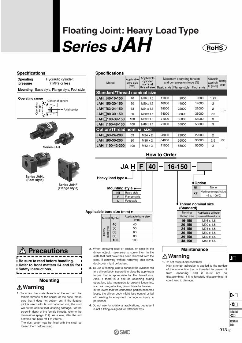
Series JAH
Series JAHL(Foot style)
Series JAHF(Flange style)
Precautions
Mounting
Warning
Maintenance
Warning
Specifications Specifications
Standard/Thread nominal size
Option/Thread nominal size
JAH�40-16-150
JAH�50-20-150
JAH�63-24-150
JAH�80-30-150
JAH�100-39-150
JAH�100-48-150
40
50
63
80
100
100
JAH�63-24-200
JAH�80-30-200
JAH�100-42-300
63
80
100
M24 x 2
M30 x 2
M42 x 3
2
2.5
3
M16 x 1.5
M20 x 1.5
M24 x 1.5
M30 x 1.5
M39 x 1.5
M48 x 1.5
1.25
2
2
2.5
3
3
How to Order
JA H
16-15020-15024-15030-15039-15048-150
M16 x 1.5M20 x 1.5M24 x 1.5M30 x 1.5M39 x 1.5M48 x 1.5
40F 16-150
40506380100
40506380100
Operatingpressure
Hydraulic cylinder:7 MPa or less
Basic style, Flange style, Foot styleMounting
Operating rangeCenter of sphere
Axial center
Ope
ratin
g ra
nge
ModelApplicablebore size
(mm)
Applicablecylindernominal
thread size
Maximum operating tensionand compression force (N)
Basic style Flange style Foot style
Rotatingangle
AllowableeccentricityU (mm)
±5°
±5°
Heavy load type
Mounting styleNilFL
Basic styleFlange styleFoot style
Applicable bore size (mm)
Model Symbol Applicable bore size(mm)
Hea
vylo
ad ty
pe
X11High temperature specifications
–5 to 100°C
OptionNil None
Thread nominal size(Standard)
Nominalthread size
Applicable cylindernominal thread size
Be sure to read before handling.Refer to front matters 54 and 55 for Safety Instructions.
1. To screw the male threads of the rod into the female threads of the socket or the case, make sure that it does not bottom out. If the floating joint is used with its rod bottomed out, the stud will not be able to float, causing damage. For the screw-in depth of the female threads, refer to the dimensions (page 914). As a rule, after the rod bottoms out, back off 1 to 2 turns.The dust cover may be fixed with the stud, so loosen them before using.
2. When screwing stud or socket, or case in the driven object, make sure to screw them in the state that dust cover has been removed from the case. If screwing without removing dust cover, duct cover might be broken.
3. To use a floating joint to connect the cylinder rod to a driven body, secure it in place by applying a torque that is appropriate for the thread size. Also, if there is a risk of loosening during operation, take measures to prevent loosening, such as using a locking pin or thread adhesive.In the event that the connected portion becomes loose, the driven body might lose control or fall off, leading to equipment damage or injury to personnel.
4. Do not use for rotational applications, because it is not a fitting designed for rotational axis.
1. Do not reuse if disassembled.High strength adhesive is applied to the portion of the connection that is threaded to prevent it from loosening, and it must not be disassembled. If it is forcefully disassembled, it could lead to damage.
28000
54000
71000
22000
36000
55000
22000
36000
55000
11000
18000
28000
54000
71000
71000
9000
14000
22000
36000
55000
55000
9000
14000
22000
36000
55000
55000
913
Floating Joint: Heavy Load Type
Series JAH RoHS
J�
Individual-X�
D-�
-X�
Technicaldata
RoHS-J.qxd 10.7.26 5:24 PM Page 2

R
ø
40506380100100
JAH40-16-150JAH50-20-150JAH63-24-150JAH80-30-150JAH100-39-150JAH100-48-150
162024303948
1.51.51.51.51.51.5
85.5101120152178191
181824384249
1.2522
2.533
110001800028000540007100071000
0.581.081.52.74.85.4
MA
222832425261
B
2531354555–
C
5059.566799696
D
9.511.513141616
E
192427303636
F
161620222428
G
323241465570
H
6380100
JAH63-24-200JAH80-30-200JAH100-42-300
243042
223
120152178
243842
22.53
280005400071000
1.52.74.8
324155
3545–
667996
131416
273036
202224
414655
52.56474
94.5112118
7494.5112
Component PartsNo.123456789
Description MaterialChromium molybdenum steel
Carbon steelChromium molybdenum steel
Carbon steelSynthetic rubber
Carbon steelCarbon steel
Rolled steel plateRolled steel plate
StudCaseRingCap Dust coverSet screwRod end nutFlangeFoot
NoteDyed black
Black zinc chromated
Black zinc chromated
Zinc chromatedZinc chromated
Black zinc chromatedBlack zinc chromated
Center of sphere
Applicablebore size
(mm)Model Nominal
size Pitch
(mm)
Mass(kg)
Allowableeccentricity
U
Maximumoperating
tension andcompression
force (N)
Center ofsphere
R
Maximum thread depth
P
Standard: Heavy Load Type Hydraulic: Up to 7 MPa
Option: Heavy Load Type Hydraulic: Up to 7 MPa
Sph
eric
al r
otat
ion
Ecc
entr
ic s
lide
Construction
Without C-dimension
914
Basic Style: JAH
JAH40 to 100
Series JAH
P0907-P0920-E.qxd 08.10.3 2:14 PM Page 914

�
�
�
�
�
�
�40506380100100
JAHF40-16-150JAHF50-20-150JAHF63-24-150JAHF80-30-150JAHF100-39-150JAHF100-48-150
��
��
�
�
�
�
� �
� �
� �
� �
� �
� �
��
��
���
��
���
���
��
��
�
�
�
�
� ��
�
�
� �
� ��
� �
� �
� �
�
�
MA
6380100
JAHF63-24-200JAHF80-30-200JAHF100-42-300
�
�
�
�
�
���
��
���
��
���
���
���
���
���
B
���
���
���
��
��
��
��
���
���
C
��
��
���
��
�� �
��
��
��
��
D
��
��
��
��
��
��
�
��
��
T
��
�
��
��
�
��
��
��
��
J
��
��
��
��
��
��
��
�
��
G
��
��
�
�
�
�
�
��
��
H
�
�
��
�
�
�
�
� �
� �
� �
�
���
���
� ��
���
��
���
� ��
��
����
������������
��������������������������������������������������������������������������
��
��
�
�
�
�
� �
� �
� �
� �
� �
� �
�� �
��
���
���
��
���
��
�
�
�
�
�
� ��
�
�
� �
� ��
� �
�
�
��
�� �
MA
��
��
��
��
���
���
B
��
�
�
�
��
��
C
��
�� �
��
��
��
��
D
�
�
�
��
�
�
E
�
�
�
�
�
F
��
���
���
���
�
���
K
��
�
��
��
��
��
L
�
��
��
��
��
��
T
�
�
N
�
��
��
��
��
��
J
��
��
��
��
�
��
G
�
�
�
�
��
��
H
������
�����������������������������������
�
�
�
�
�
���
���
��
��
��
���
�
�
��
��
��
��
�
��
�
�
�
���
���
�
��
��
��
��
��
��
��
��
��
��
��
�
�
�
��
�
�
�
�
� �
�
�
��
��
���
���
�� �
���
��
���
�� ��
��
����
�
�
������ � !"#���
�""$%&'($�
(��� !%)�
����*�+�$ ,��%�'$
!%)� -%�&#
*'!!
�./�
�$$�0'($��&&����%&%�1
U
*'�%�2�
�#��'+ +�"�#
P
*'�%�2��"��'�%�/
���!%�� '�+&��"��!!%��
��&� �,�
������ � !"#���R
Standard: Heavy Load Type �1+�'2$%&3 4" �� � *-'
Option: Heavy Load Type �1+�'2$%&3 4" �� � *-'
������ � !"#���
������ � !"#���
�""$%&'($�
(��� !%)�
����*�+�$ ,��%�'$
!%)� -%�&#
*'!!
�./�
�$$�0'($��&&����%&%�1
U
*'�%�2�
�#��'+ +�"�#
P
*'�%�2��"��'�%�/
���!%�� '�+&��"��!!%��
��&� �,�
������ � !"#���
R
Standard: Heavy Load Type �1+�'2$%&3 4" �� � *-'
Option: Heavy Load Type �1+�'2$%&3 4" �� � *-'
����
����
�����
����
�����
�����
�����
����
�����
����
����
�����
����
�����
�����
�����
����
�����
���
Flange Style: JAFH
JAFH40 to 100
Foot Style: JAHL
JAHL40, 50
JAHL63 to 100
Floating Joint: Heavy Load Type Series JAH
J�
Individual-X�
D-�
-X�
Technicaldata
P0907-P0920-E.qxd 08.10.3 2:14 PM Page 915

Precautions
Mounting
Warning
Maintenance
Warning
Specifications
Model
JB12-3-050
JB16-4-070
JB20-5-080
JB25-6-100
JB40-8-125
JB63-10-150
JB80-16-200
JB100-20-250
JB140-22-250
JB160-24-300
12
16
20
25
32, 40
50, 63
80
100
125, 140
160
0.5
0.5
0.5
0.5
0.75
1
1.25
2
2.5
3
Center of sphere
Axial center
Ope
ratin
gra
nge
Specifications
Operating range
How to Order
J B 40 8-125
12162025406380100140160
12162025
32, 4050, 63
80100
125, 140160
X11
Nil
Operatingpressure
Air pressure compact cylinder1 MPa or less
Applicablebore size
(mm)
Applicable cylinder
nominal thread size
Maximum operating tensionand compression force (N)
Compression side Tension side
Rotatingangle
AllowableeccentricityU (mm)
M3 x 0.5
M4 x 0.7
M5 x 0.8
M6 x 1
M8 x 1.25
M10 x 1.5
M16 x 2
M20 x 2.5
M22 x 2.5
M24 x 3
112
200
1100
2500
6000
11000
18000
28000
54000
71000
112
200
300
500
1300
3100
5000
7900
15300
20000
±5°
For compact cylinders/Female thread
Applicable bore size (mm)
Symbol Applicable bore size(mm)
High temperaturespecifications
–5 to 100°C
None
Thread nominal size
Option
Nominalthread size
Applicable cylindernominal thread size
M3 x 0.5M4 x 0.7M5 x 0.8M6 x 1
M8 x 1.25M10 x 1.5M16 x 2
M20 x 2.5M22 x 2.5M24 x 3
3-0504-0705-0806-1008-125
10-15016-20020-25022-25024-300
Be sure to read before handling.Refer to front matters 54 and 55 for Safety Instructions.
1. To screw the male threads of the rod into the female threads of the socket or the case, make sure that it does not bottom out. If the floating joint is used with its rod bottomed out, the stud will not be able to float, causing damage. For the screw-in depth of the female threads, refer to the dimensions (page 917). As a rule, after the rod bottoms out, back off 1 to 2 turns.The dust cover may be fixed with the stud, so loosen them before using.
2. When screwing stud or socket, or case in the driven object, make sure to screw them in the state that dust cover has been removed from the case. If screwing without removing dust cover, duct cover might be broken.
3. To use a floating joint to connect the cylinder rod to a driven body, secure it in place by applying a torque that is appropriate for the thread size. Also, if there is a risk of loosening during operation, take measures to prevent loosening, such as using a locking pin or thread adhesive.In the event that the connected portion becomes loose, the driven body might lose control or fall off, leading to equipment damage or injury to personnel.
4. Do not use for rotational applications, because it is not a fitting designed for rotational axis.
1. Do not reuse if disassembled.High strength adhesive is applied to the portion of the connection that is threaded to prevent it from loosening, and it must not be disassembled. If it is forcefully disassembled, it could lead to damage.
916
Floating Joint: For Compact Cylinders
Series JB RoHS
RoHS-J.qxd 10.7.26 5:24 PM Page 3

R
ø
R
ø
Component PartsNo.12345
Description MaterialFree-cutting steel
BrassStainless steel
BrassSynthetic rubber
NoteElectroless nickel platedElectroless nickel plated
Electroless nickel plated
StudCaseRingSocketDust cover
No.123456
Description MaterialChromium molybdenum steel
Carbon steelChromium molybdenum steel
Carbon steelSynthetic rubber
Carbon steel
NoteDyed black
Black zinc chromated
Black zinc chromated
Zinc chromated
StudCaseRingCap Dust coverSet screw
1216202532, 4050, 6380100125, 140160
JB12-3-050JB16-4-070JB20-5-080JB25-6-100JB40-8-125JB63-10-150JB80-16-200JB100-20-250JB140-22-250JB160-24-300
34568
1016202224
0.50.70.81
1.251.52
2.52.53
24.526.5333851
62.580.5101129149
7789131518243842
0.50.50.50.50.75
11.25
22.53
112200300500
1300310050007900
1530020000
1122001100250060001100018000280005400071000
0.020.020.040.070.150.290.561.042.64.5
MA
34.556
8.51016211720
B
46
6.58111320262226
C
16162124314150
59.57996
D
22
4.556
7.59.511.51416
E
6678111419243036
F
557811
13.516202224
G
10101317222732414655
H
1315
19.522.529
35.547.559
71.583
(mm)
Center of sphere
Applicablebore size
(mm)Model Nominal
size PitchMass(kg)
Maximum operating tensionand compression force (N)
Compression Tension
Allowableeccentricity
U
Maximumthread
depth P
Centerof sphere
R
917
Construction
ø12, ø16 ø20 to ø160
Basic Style: JB
JB20, 16
JB20 to 160
Floating Joint: For Compact Cylinders Series JB
Center of sphere
J�
Individual-X�
D-�
-X�
Technicaldata
P0907-P0920-E.qxd 08.10.3 2:14 PM Page 917

Specifications
Series JS
Precautions
Mounting
Warning
Maintenance
Warning
Specifications
Operating range
JS10-4-070
JS16-5-080
JS20-8-125
JS32-10-125
JS40-14-150
JS63-18-150
10
10, 16
20
25, 32
40
50, 63
M4 x 0.7
M5 x 0.8
M8 x 1.25
M10 x 1.25
M14 x 1.5
M18 x 1.5
80
210
1100
2500
6000
11000
0.5
0.5
0.5
0.5
0.75
1
–
–5 to 70°C
J S 32
Applicable bore size(mm)
1010, 16
2025, 32
4050, 63
Dust cover material
10-125
Nominal thread size
4-070 5-080 8-12510-12514-15018-150
Applicable cylindernominal thread size
M4 x 0.7M5 x 0.8M8 x 1.25M10 x 1.25M14 x 1.5M18 x 1.5
How to Order
Operatingpressure
Pneumatic cylinder:1 MPa or less
Hydraulic cylinder: 3.5 MPa or less
Basic styleMounting
Be sure to read before handling.Refer to front matters 54 and 55 for Safety Instructions.
1. For the screw-in depth of the female threads, refer to the dimensions (page 920).
2. When screwing stud or socket, or case in the driven object, make sure to screw them in the state that dust cover has been removed from the case. If screwing without removing dust cover, duct cover might be broken.
3. To use a floating joint to connect the cylinder rod to a driven body, secure it in place by applying a torque that is appropriate for the thread size. Also, if there is a risk of loosening during operation, take measures to prevent loosening, such as using a locking pin or thread adhesive.In the event that the connected portion becomes loose, the driven body might lose control or fall off, leading to equipment damage or injury to personnel.
4. Do not use for rotational applications, because it is not a fitting designed for rotational axis.
1. Do not reuse if disassembled.High strength adhesive is applied to the portion of the connection that is threaded to prevent it from loosening, and it must not be disassembled. If it is forcefully disassembled, it could lead to damage.
ModelApplicablebore size
(mm)
Applicablecylindernominal
thread size
AllowableeccentricityU (mm)
Operating pressureAir
pressurecylinder
Hydrauliccylinder
Ambienttemperature
Maximumoperating
tension andcompression
force (N)
(1)
1 MPaor less 3.5 MPa
or less
(2)
Note 1) Think of applicable bore size as a guide. For details, confirm the rod end thread diameter of a cylinder to be used in the catalog.
Note 2) For 3.5 MPa hydraulic cylinders, operate within the maximum tension and compression force.
Stainlesssteel type
Applicablebore size (mm)
Symbol
101620324063
SymbolNilS
MaterialFluororubberSilicon rubber
Symbol
Stainless steel 304
Cylinder connection threadsNo leakage of water, etc., fromthe threads into the interior.
Internal grease:Using for food processing machinery
Dust cover (fluororubber, silicon rubber)• The shape of the cover prevents residual liquid.• Improved sealing
Center of sphere
Axial center
Ope
ratin
gra
nge
918
Floating Joint: Stainless Steel Type
Series JS RoHS
RoHS-J.qxd 10.7.26 5:24 PM Page 4

No.123456
DescriptionStudCaseRingCap Dust coverSet screw
MaterialStainless steel (Thread parts)
Stainless steelChromium molybdenum steel
Carbon steelFluororubber/Silicon rubber
Carbon steel
NoteElectroless nickel plated
Electroless nickel platedElectroless nickel plated
7 Rod end nut Stainless steel
Component Parts Component PartsNo.123456
DescriptionStudCaseRingSocketDust coverRod end nut
MaterialStainless steelStainless steelStainless steelStainless steel
Fluororubber/Silicon rubberStainless steel
Note
Model
JS10 JS16 JS20 JS32 JS40 JS63
Fluoro rubberPart no. for dust cover
Silicon rubber
Dust coverWhen the dust cover is damaged and deteriorated, order with the part number as shown below.
Rod end nutRod end nut (1 pc.) is attached to the standard type of Series JS.But if it is needed additionally, order it as follows. For details, refer to page 920. Example······Nut for JS40
P21530511 P21530521 P2153151 P2153251 P2153351 P2153451
P21530512 P21530522 P2153152 P2153252 P2153352 P2153452
919
Construction
ø10, ø16 ø20 to ø63
Replacement Parts
Floating Joint: Stainless Steel Type Series JS
J�
Individual-X�
D-�
-X�
Technicaldata
P0907-P0920-E.qxd 08.10.3 2:14 PM Page 919

�
�
� �
�
�
�
�
��
�
�
�
��
�
�
� � �
�
�
�
JS10, 16
JS20, 32, 40, 63
�
�
�
�
�
JS10-4-070 JS16-5-080
M
� � ���
� � ���
A
��
����
���
���
����
JS20-8-125 JS32-10-125
� � ����
�� � ����
����
����
���
���
JS40-14-150 JS63-18-150
�� � ���
�� � ���
��
����
����
����
B
���
��
����
����
����
��
C
���
����
D
��
��
��
��
��
��
E
���
�
���
�
�
�
F
�
�
�
�
��
��
G
�
�
�
�
��
����
H
�
��
��
��
��
��
J
����
��
����
��
����
����
��
��
����
����
��
����
���
���
���
���
����
�
��
���
����
����
����
�����
!""#
!""#
��$%&'()'�*
� � ���
� � ���
� � ����
�� � ����
�� � ���
�� � ���
H���
�
�
�
�
��
B�
�
��
��
��
��
C���
���
��
����
����
����
D���
���
����
����
��
��
��*)�& �+ $(,�&�
� $� ),� (&�%'$'�* $(-**�& +�& %��%. � "" '* ),� %-$� �+ "�/*)'*0"-�� ),&�-� �+ 1���
��*)�& �+ $(,�&�
-�� ),&�-���(),
P
��*)�& �+$(,�&�
R
����2-3���%%�*)&'%')4
U
-�� �(�&-)'*0 )�*$'�*-*� %�"(&�$$'�*+�&%� !5#
Rod end nutJS10 nutJS16 nutJS20 nutJS32 nutJS40 nutJS63 nut
d6 7,&�-� *�"'*-� $'8�
��9
Dimensions
���
Series JS
P0907-P0920-E.qxd 08.10.3 2:14 PM Page 920
Related Documents