The Field Orientation Principle in Control of Induction Motors

Welcome message from author
This document is posted to help you gain knowledge. Please leave a comment to let me know what you think about it! Share it to your friends and learn new things together.
Transcript

The Field Orientation Principle in Control of Induction Motors

THE KLUWER INTERNATIONAL SERIES IN ENGINEERING AND COMPUTER SCIENCE
POWER ELECTRONICS AND POWER SYSTEMS
Consulting Editor
Thomas A. L1po University of Wisconsin-Madison
Other books in the series:
SPOT PRICING OF ELECTRICITY, F. C. Schweppe, M. C. Caramanis, R. D. Tabors, R. E. Bohn
ISBN 0-89838-260-2
RELIABILITY ASSESSMENT OF LARGE ELECTRIC POWER SYSTEMS, R. Billington, R. N. Allan
ISBN 0-89838-266-1
MODERN POWER SYSTEMS CONTROL AND OPERATION, A. S. Debs ISBN: 0-89838-265-3
ELECTROMAGNETIC MODELLING OF POWER ELECTRONIC CONVERTERS, J. A. FelTeira
ISBN: 0-7923-9034-2
ENERGY FUNCTION ANALYSIS FOR POWER SYSTEM STABILITY, M. A. Pai
ISBN: 0-7923-9035-0
INDUSTRIAL ENERGY MANAGEMENT: PRINCIPLES AND APPLICATIONS, G. Petrecca
ISBN: 0-7923-9305-8

The Field Orientation Principle in Control of
Induction Motors
Andrzej M. Trzynadlowski University of Nevada, Reno
.... " SPRINGER SCIENCE+BUSINESS MEDIA, LLC
Llbrary of Congress Cataloglng·ln-Publicatlon Data
Trzynadlowski, Andrzej. The field orientation principle in control of induction motors 1
Andrzej M. Trzynadlowski. p. cm. -- (The Kluwer international series in engineering and
computer science : SECS 258. Power electronics and power systems) Includes bibliographical references (p. ) and index. ISBN 978-0-7923-9420-4 ISBN 978-1-4615-2730-5 (eBook) DOI 10.1007/978-1-4615-2730-5 1. Electric motors, Induction--Automatic control. 2. Field
orientation principle (Electric engineering) 1. Title. II. Series: Kluwer international series in engineering and computer science : SECS 258. III. Series: Kluwer international series in engineering and computer science. Power electronics & power systems. TK2785.TI6 1994 621.46--dc20 93-33661
CIP
Copyright © 1994 by Springer Science+Business Media New York Originally published by Kluwer Academic Publishers. in 1994 Softcover reprint of the hardcover 1 st edition 1994 AII rights reserved. No part of this publication may be reproduced, stored in a retrieval system or transmitted in any form or by any means, mechanical, photo-copying, record ing, or otherwise, without the prior written permission of the publisher, Springer Science+ Business Media, LLC.
Printed on acid-free paper.

To the memory of my Grandmother
Izabela Prdszynska
v
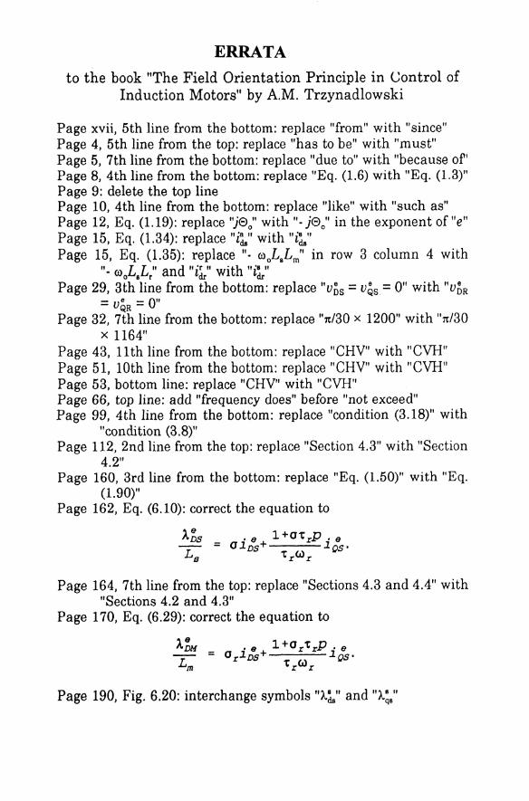
ERRATA to the book "The Field Orientation Principle in Control of
Induction Motors" by AM. Trzynadlowski
Page xvii, 5th line from the bottom: replace "from" with "since" Page 4, 5th line from the top: replace "has to be" with "must" Page 5, 7th line from the bottom: replace "due to" with "because or' Page 8, 4th line from the bottom: replace "Eq. (1.6) with "Eq. (1.3)" Page 9: delete the top line Page 10, 4th line from the bottom: replace "like" with "such as" Page 12, Eq. (1.19): replace "jeo" with ". jeo" in the exponent of "e" Page 15, Eq. (1.34): replace "i~" with "i~" Page 15, Eq. (1.35): replace ". {j)oLaLm" in row 3 column 4 with
". (j) L L " and "ir " with ''is'' o s r ~ ~
Page 29, 3th line from the bottom: replace "vos = vQs = 0" with "VOR - ve - 0" - QR-
Page 32, 7th line from the bottom: replace "n/30 x 1200" with "n/30 x 1164"
Page 43, 11th line from the bottom: replace "CHV" with "CVH" Page 51, 10th line from the bottom: replace "CHV" with "CVH" Page 53, bottom line: replace "CHV" with "CVH" Page 66, top line: add "frequency does" before "not exceed" Page 99, 4th line from the bottom: replace "condition (3.18)" with
"condition (3.8)" Page 112, 2nd line from the top: replace "Section 4.3" with "Section
4.2" Page 160, 3rd line from the bottom: replace "Eq. (1.50)" with "Eq.
(1.90)" Page 162, Eq. (6.10): correct the equation to
A~S - -
Page 164, 7th line from the top: replace "Sections 4.3 and 4.4" with "Sections 4.2 and 4.3"
Page 170, Eq. (6.29): correct the equation to
Page 190, Fig. 6.20: interchange symbols "A.~" and "A.~s"

Contents
Nomenclature IX
Preface xv
1 DYNAMIC MODEL OF THE INDUCTION MOTOR 1
1.1 Space Vectors in Stator Reference Frame 1 1.2 Direct and Inverse.Three·Phase to Stator Reference
Frame Transformations 8 1.3 Voltage and Current Equations in Stator Reference
Frame 11 1.4 Torque Equation 16 1.5 Dynamic Equivalent Circuit 20 1.6 Direct and Inverse Stator to Excitation Reference
Frame Transformations 25 1.7 Motor Equations in Excitation Reference Frame 28 1.8 Examples and Simulations 30
2 SCALAR CONTROL OF INDUCTION MOTORS 43
2.1 The r Equivalent Circuit of an Induction Motor 44 2.2 Principles of the Constant VoltslHertz Control 47 2.3 Scalar Speed Control System 52 2.4 The r' Equivalent Circuit of an Induction Motor 54 2.5 Principles of the Torque Control 56 2.6 Scalar Torque Control System 59 2.7 Examples and Simulations 66
3 FIELD ORIENTATION PRINCIPLE 87
3.1 Optimal Torque Production Conditions 88 3.2 Dynamic Block Diagram of an Induction Motor in
the Excitation Reference Frame 90 3.3 Field Orientation Conditions 93
4 CLASSIC FIELD ORIENTATION SCHEMES 97
4.1 Field Orientation with Respect to the Rotor Flux Vector 98
4.2 Direct Rotor Flux Orientation Scheme 100 4.3 Indirect Rotor Flux Orientation Scheme 106
vii

CONI'ENI'S
4.4 Examples and Simulations
5 INVERTERS
5.1 Voltage Source Inverter 5.2 Voltage Control in Voltage Source Inverters 5.3 Current Control in Voltage Source Inverters 5.4 Current Source Inverter 5.5 Examples and Simulations
6 REVIEW OF VECTOR CONTROL SYSTEMS
108
125
126 130 138 141 144
159
6.1 Systems with Stator Flux Orientation 160 6.2 Systems with Airgap Flux Orientation 168 6.3 Systems with Current Source Inverters 175 6.4 Observers for Vector Control Systems 176 6.5 Adaptive Schemes 185 6.6 Position and Speed Control of Field-Oriented
Induction Motors 189 6.7 Examples and Simulations 197
Bibliography 225
Index 253
viii

N <nJenclature
Principal Symbds
a, b, c dx, dy, dz 9'M,~, ~
~.,~.
1M
ImCJ% IR Ii Ir Is I.,all I.,mCJ% I.,ral I.1l> 1sT ~al
switching variables of an inverter duty ratios of states X, Y, Z of an inverter vectors of magnetomotive forces produced by the stator phase currents,
Alph vector of stator magnetomotive force in the stator reference frame, A magnitude of the vector of stator magnetomotive force, A components of the vector of stator magnetomotive force in the excitation
reference frame, A components of the vector of stator magnetomotive force in the stator
reference frame, A supply frequency, Hz rated supply frequency, Hz current tolerance band of an inverter, A phasor of magnetizing current in the steady-state r equivalent circuit,
Nph phasor of magnetizing current in the steady-state f' equivalent circuit,
Nph phasor of magnetizing current in the steady-state T equivalent circuit,
Nph phasor of rotor current in the steady-state r equivalent circuit, Alph phasor of rotor current in the steady-state f' equivalent circuit, Nph phasor of rotor current in the steady-state T equivalent circuit, Nph phasor of stator current, Nph d.c. supply current of a current source inverter, A r.m.s. value of magnetizing current in the steady-state r equivalent
circuit, Nph r.m.s. value of magnetizing current in the steady-state f' equivalent
circuit, Nph r.m.s. value of magnetizing current in the steady-state Tequivalent circuit,
Nph amplitude of fundamental output current of an inverter, A r.m.s. value of rotor current in the steady-state r equivalent circuit, Nph r.m.s. value ofrotor current in the steady-state f' equivalent circuit, Nph r.m.s. value ofrotor current in the steady-state Tequivalent circuit, Alph r.m.s. value of stator current, Nph maximum allowable r.m.s. value of stator current, Nph peak value of stator current, Nph rated r.m.s. value of stator current, Nph r.m.s. value of flux-producing current, Alph r.m.s. value of torque-producing current, Nph fundamental phase-A current of an inverter, A
ix
;;,.'
;;"
.; (
"a' ~, ". ial ias, 4.., i.s i~R> iQa
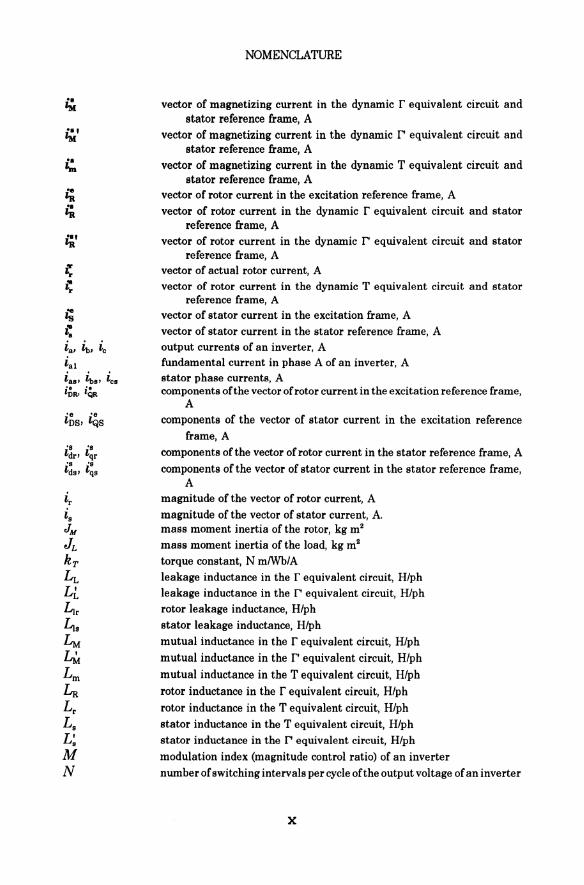
NOMENCLATURE
vector of magnetizing current in the dynamic r equivalent circuit and stator reference frame, A
vector of magnetizing current in the dynamic I" equivalent circuit and stator reference frame, A
vector of magnetizing current in the dynamic T equivalent circuit and stator reference frame, A
vector of rotor current in the excitation reference frame, A vector of rotor current in the dynamic r equivalent circuit and stator
reference frame, A vector of rotor current in the dynamic I" equivalent circuit and stator
reference frame, A vector of actual rotor current, A vector of rotor current in the dynamic T equivalent circuit and stator
reference frame, A vector of stator current in the excitation frame, A vector of stator current in the stator reference frame, A output currents of an inverter, A fundamental current in phase A of an inverter, A stator phase currents, A components of the vector ofrotor current in the excitation reference frame,
A components of the vector of stator current in the excitation reference
frame, A components of the vector of rotor current in the stator reference frame, A components of the vector of stator current in the stator reference frame,
A magnitude of the vector of rotor current, A magnitude of the vector of stator current, A. mass moment inertia of the rotor, kg mil mass moment inertia of the load, kg mil torque constant, N mlWbiA leakage inductance in the r equivalent circuit, H/ph leakage inductance in the I" equivalent circuit, H/ph rotor leakage inductance, H/ph stator leakage inductance, H/ph mutual inductance in the r equivalent circuit, H/ph mutual inductance in the r' equivalent circuit, H/ph mutual inductance in the T equivalent circuit, H/ph rotor inductance in the r equivalent circuit, H/ph rotor inductance in the T equivalent circuit, H/ph stator inductance in the T equivalent circuit, H/ph stator inductance in the I" equivalent circuit, H/ph modulation index (magnitude control ratio) of an inverter number of switching intervals per cycle of the output voltage of an inverter
x
Nr
N. nM
nM,rat
nM,oyn
P Pelec
Pinp
Pmech
Pout
PF p RR RR Rr R~ Rs S
T TL Tpeak
Trot
Totart
t V. Vtk
Vs
Vs,rat
Vmax
v Vx, Vy, Vz
v: v: v; if. Va. Vb. Vc
Vab. Vbc. Vca
Vas' Vb., Vcs
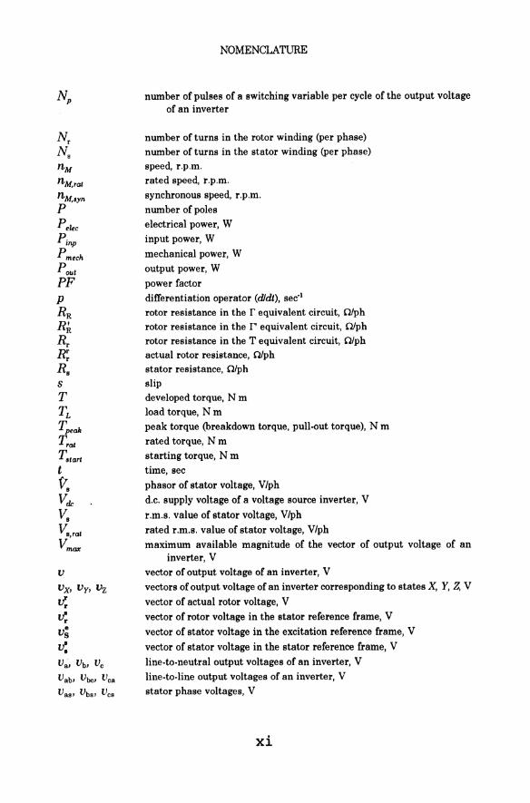
NOMENCLATURE
number of pulses of a switching variable per cycle of the output voltage of an inverter
number of turns in the rotor winding (per phase) number of turns in the stator winding (per phase) speed, r.p.m. rated speed, r.p.m. synchronous speed, r.p.m. number of poles electrical power, W input power, W
mechanical power, W output power, W power factor differentiation operator (dldt), sec'! rotor resistance in the r equivalent circuit, a/ph rotor resistance in the r' equivalent circuit, a/ph rotor resistance in the T equivalent circuit, a/ph actual rotor resistance, a/ph stator resistance, a/ph slip developed torque, N m load torque, N m peak torque (breakdown torque, pull-out torque), N m rated torque, N m starting torque, N m time, sec
phasor of stator voltage, V/ph d.c. supply voltage of a voltage source inverter, V
r,m,s, value of stator voltage, V/ph rated r,m,s, value of stator voltage, V/ph
maximum available magnitude of the vector of output voltage of an inverter, V
vector of output voltage of an inverter, V vectors of output voltage of an inverter corresponding to states X, Y, Z, V
vector of actual rotor voltage, V
vector of rotor voltage in the stator reference frame, V
vector of stator voltage in the excitation reference frame, V
vector of stator voltage in the stator reference frame, V
line-to-neutral output voltages of an inverter, V line-to-line output voltages of an inverter, V stator phase voltages, V
xi

y'
E> o
E> r
E> 8
~'
NOMENCLATURE
components of the vector of stator voltage in the excitation reference frame, V
components of the vector of rotor voltage in the stator reference frame, V components of the vector of stator voltage in the stator reference frame,
V rotor leakage reactance, Q/ph stator leakage reactance, C"l/ph magnetizing reactance, Q/ph rotor reactance, ClIph stator reactance, C"llph coefficient of transformation of the Tequivalent circuit to the r equivalent
circuit coefficient oftransformationofthe Tequivalent circuit to the [" equivalent
circuit efficiency
time integral of slip speed, rad angular displacement of the rotor of a P-pole motor, rad angular position (phase) of the vector of airgap flux in the stator reference
frame, rad angular displacement of the rotor of a 2-pole motor, rad angular position (phase) of the vector of rotor flux in the stator reference
frame, rad angular position (phase) of the vector of stator flux in the stator reference
frame, rad. Also, that of the vector of stator magnetomotive force, rad. phasor of rotor flux in the steady-state r equivalent circuit, Wb/ph phasor of rotor flux in the steady-state [" equivalent circuit, Wblph phasor of rotor flux in the steady-state T equivalent circuit, Wb/ph phasor of stator flux, Wblph
r.m.s. value of rotor flux in the steady-state r equivalent circuit, Wblph
r.m.s. value ofrotor flux in the steady-state [" equivalent circuit, Wb/ph r.m.s. value of stator flux, Wblph vector of airgap flux in the excitation reference frame, Wb vector of airgap flux in the dynamic T equivalent circuit and stator
reference frame, Wb vector of rotor flux in the excitation reference frame, Wb vector of rotor flux in the dynamic r equivalent circuit and stator
reference frame, Wblph vector of rotor flux in the dynamic [" equivalent circuit and stator
reference frame, Wblph vector of actual rotor flux, Wb vector of rotor flux in the dynamic Tequivalent circuit and stator reference
frame, Wb vector of stator flux in the excitation reference frame, Wb vector of stator flux in the stator reference frame, Wb
xii
co
COral
COM
COo
COr
CO,/
CO.yn
Subscripts
a, b,e all D d de L,l L M,m M max o Q q R, r
NOMENCLATURE
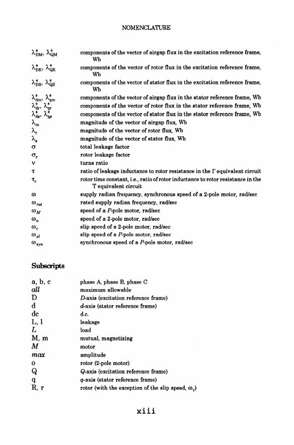
components of the vector of airgap flux in the excitation reference frame, Wb
components of the vector of rotor flux in the excitation reference frame, Wb
components of the vector of stator flux in the excitation reference frame, Wb
components of the vector of airgap flux in the stator reference frame, Wb components of the vector of rotor flux in the stator reference frame, Wb components of the vector ofstator flux in the stator reference frame, Wb magnitude of the vector of airgap flux, Wb magnitude of the vector of rotor flux, Wb magnitude of the vector of stator flux, Wb total leakage factor rotor leakage factor turns ratio ratio of leakage inductance to rotor resistance in the r equivalent circuit rotor time constant, i.e., ratio of rotor inductance to rotor resistance in the
T equivalent circuit supply radian frequency, synchronous speed of a 2.pole motor, rad/sec rated supply radian frequency, rad/sec speed of a P.pole motor, rad/sec speed of a 2.pole motor, rad/sec slip speed of a 2·pole motor, rad/sec slip speed of a P·pole motor, rad/sec synchronous speed of a P·pole motor, rad/sec
phase A, phase B, phase C
maximum allowable D-axis (excitation reference frame) d-axis (stator reference frame) d.c. leakage load mutual, magnetizing
motor amplitude rotor (2.pole motor) Q.axis (excitation reference frame) q·axis (stator reference frame) rotor (with the exception of the slip speed, cor)
xiii

rat S,s sl syn T,T X, Y,Z
Supersmpts
e, e r, r s,s *
Abbreviations
BJT CSI CVH FOP GTO IGBT MCT MOSFET MRAS PI PID PWM RPWM SCR SIT SITH SOAR TC UFO VSC VSI
NOMENCLATURE
rated stator slip synchronous torque state X, state Y, state Z of an inverter
excitation reference frame actual rotor quantities
stator reference frame conjugate or reference r' equivalent circuit (unless otherwise specified)
Bipolar Junction Transistor
Current Source Inverter
Constant Volts/Hertz Field Orientation Principle Gate Turn·Off Thyristor Insulated Gate Bipolar Transistor MOS·Controlled Thyristor Metal·Oxide Semiconductor Field·Effect Transistor Model Reference Adaptive System Proportional.Plus.Integral (controller) Proportional.Plus.lntegral.Plus.Derivative (controller)
Pulse Width Modulation Random Pulse Width Modulation Silicon Controlled Rectifier Static Induction Transistor Static Induction Thyristor Safe Operating Area Torque Control Universal Field Orientation Variable Structure Control Voltage Source Inverter
xiv

Prefaoo
Induction motors, particularly those of the squirrel-cage type, have been for almost a century industry'S principal workhorse. Until the early seventies, they had been mostly operated in the constant-frequency, constant-voltage, uncontrolled mode which even today is still most common in practice. Adjustable-speed drives had been based on d.c. motors, mainly in the classic Ward-Leonard arrangement.
The advent of thyristors, the fIrst controlled semiconductor power switches and, consequently, the development of variable-frequency converters based on these switches, made possible wide-range speed control of induction motors. The most popular, so-called scalar control methods consist in simultaneous adjustments of the frequency and magnitude of the sinusoidal voltage or current supplied to the motor. This allows making steady-state operating characteristics of an induction motor similar to those of a d.c. motor. Adjustable-speed a.c. drive systems, employing scalar control principles have been replacing the d.c. drives in numerous industrial applications, such as pumps, fans, compressors, and conveyor belts. Induction motors have here a clear competitive edge over d.c. machines. They are significantly less expensive, more robust, and capable of reliable operation in harsh ambient conditions, even in an explosive atmosphere.
It must be stressed, that scalar control does not make an induction motor dynamically equivalent to a d.c. motor. Accurate position control, for instance, is not possible, since precise control of the instantaneous torque developed in the motor is needed to realize the required speed trajectory. This, in turn, means that it is the instantaneous stator current that has to be controlled. Scalar control applies to steady-state operation of the motor only, while no special allowance for transient operating conditions appears in the control principles.
Brushes, affixed to the stator, and commutator on the rotor provide in a d.c. motor a direct, physical link between the field and armature circuits of the machine. Proper positioning of the brushes ensures optimal conditions for torque production under all operating conditions. This is not the case in an induction motor, whose rotor is physically isolated from the stator. Therefore, to optimize the torque production conditions in this motor, an algorithmic equivalent of the d.c. motor's physical stator-rotor link has to be provided by an appropriate control technique. Such techniques are based on the, so-called, Field Orientation Principle which is the topic of this book.
xv

PREFACE
The Field Orientation Principle was fIrst formulated by Haase, in 1968, and Blaschke, in 1970. At that time, their ideas seemed impractical because of the insufficient means of implementation. However, in the early eighties, technological advances in static power converters and microprocessor-based control systems made the high-performance a.c. drive systems fully feasible. Since then, hundreds of papers dealing with various aspects of the Field Orientation Principle have appeared every year in the technical literature, and numerous commercial high-performance a.c. drives based on this principle have been developed. The term "vector control" is often used with regard to these systems. Today, it seems certain that almost all d.c. industrial drives will be ousted in the foreseeable future, to be, in major part, superseded by a.c. drive systems with vector controlled induction motors. This transition has already been taking place in industries of developed countries. Vector controlled a.c. drives have been proven capable of even better dynamic performance than d.c. drive systems, because of higher allowable speeds and shorter time constants of a.c. motors.
It should be mentioned that the Field Orientation Principle can be used in control not only of induction (asynchronous) motors, but of all kinds of synchronous motors as well. Vector controlled drive systems with the socalled brushless d.c. motors have found many applications in highperformance drive systems, such as machine tools and industrial robots. Large, cycloconverter-fed synchronous motors can also be controlled on the basis of the Field Orientation Principle. The same applies to recently developed synchronous reluctance motors. This book, however, is focused on induction motors only, on the assumption that these machines represent a distinct majority in industrial drive systems. Actually, fIeld orientation in synchronous motors is simpler than in induction motors, since the position of the flux vector generated in the rotor is· easy to monitor. Therefore, interested readers should not encounter any serious difficulties in extending the acquired knowledge of the Field Orientation Principle to the other kinds of a.c. motors. It is also worth mentining that there exist concepts of vector control which do not directly employ the Field Orientation Principle, such as the theory of spiral vectors and field acceleration. It is too early to judge whether these alternative approaches to control of a.c. motors will gain popularity in the commercial practice.
It is assumed that the reader is familiar with the basic concepts of electromechanical energy conversion and electric machines. The Field Orientation Principle is presented both in a formal manner, based on the vector theory of a.c. machines, and in simple engineering terms. In Chapter 1, dynamic models, based on the concept of space vectors of motor
xvi
PREFACE
quantities, are compared with the well known phasor-based, steady-state equivalent circuits of an induction machine. Explanation of the relation between vectors and phasors allows viewing the per-phase, steady-state equivalent circuit of the motor as a special case of the dynamic model. Electromagnetic matrix equations and the torque equation, in both the stator (stationary) and excitation (rotating) reference frames, are then derived. They provide means for computer simulation of induction motors and serve as a background for the Field Orientation Principle.
Before the introduction of the field orientation concept, scalar control techniques for adjustable-speed, induction-motor drives are described in Chapter 2. Next, in Chapter 3, control characteristics of a separately excited d.c. motor are explained, and fundamentals of the Field Orientation Principle are introduced. Chapter 4 presents the Field Orientation Principle as a means of optimizing the torque-production conditions and of decoupling the flux and torque control in an induction motor. Both the direct and indirect approaches to rotor flux orientation in induction motors are described. Chapter 5 is devoted to power inverters, which constitute the controllable supply source for induction motors. Chapter 6, which concludes the book, contains a review of vector control systems for induction motors. Stator and airgap flux orientation schemes, systems with current source inverters, observers of motor variables, estimation of motor parameter, adaptive tuning, and speed and position control systems for field-oriented induction motors are briefly examined there.
To facilitate the reader's understanding of the material presented, numerous numerical examples and computer simulations are included. It must be stressed that the book is not intended to exhaustively cover the latest achievements in the area of high-performance a.c. drives, and it is not an engineering manual. It is primarily addressed to practicing engineers, graduate students in power and control programs, and those researchers who intend to enter the field of induction motor control but lack a sufficient background in the dynamics of these motors. Hence, the book should be viewed as a graduate-level textbook rather than as a sophisticated scientific monograph.
The book has originated from the lecture notes prepared by the author for a graduate course in electric drive systems and power electronics, taught from 1990 at the University of Nevada, Reno. The existing books and papers have been found either too superficial or too complicated for readers familiar with only the steady-state theory of electrical machines, to which typical undergraduate curricula are limited. It is hoped that this book will fill that gap.
xvii

PREFACE
The author wants to acknowledge the invaluable help of Dr. Ronald E. Colyer of the Royal Military College of Science in Great Britain, whose precious comments and suggestions greatly enhanced quality of the book. Expressions of gratitude and apology are directed to the author's wife, Dorota, and children, Bart and Nicole, who patiently endured the long working hours of their husband and father.
xviii
The Field Orientation Principle· in Control of Induction Motors
Related Documents